Itron WF111 IEEE 802.11 b/g/n Wi-Fi module User Manual User Guide
Itron, Inc. IEEE 802.11 b/g/n Wi-Fi module User Guide
Itron >
Host Manual

OpenWay® Riva Socket Based Router
User Guide
Technical
Communications knowledge to shape your future
Identification
OpenWay® Riva Socket Based Router User Guide
18 April 2018 DRAFT
Copyright
© 2018 Itron, Inc. All rights reserved.
Confidentiality Notice
The information contained herein is proprietary and confidential and is being provided
subject to the condition that (i) it be held in confidence except to the extent required
otherwise by law and (ii) it will be used only for the purposes described herein. Any third
party that is given access to this information shall be similarly bound in writing.
Trademark Notice
Itron is a registered trademark of Itron, Inc.
All other product names and logos in this documentation are used for identification purposes
only and may be trademarks or registered trademarks of their respective companies.
Suggestions
For more information about Itron or Itron products, see www.itron.com.
If you have questions or comments about the software or hardware product, contact Itron
Technical Support Services.
Contact
• Email: support@itron.com
• Internet: support.itron.com
• Telephone Itron Technical Support North America: 1-877-487-6602
For technical support contact information by region, go to www.itron.com and select your
country and language.

Contents
Chapter 1 Important Product and Compliance Information............................1
FCC Compliance...................................................................................................................................................1
Factory Repair of Meters...................................................................................................................................... 2
Battery...................................................................................................................................................................3
Standards..............................................................................................................................................................3
Chapter 2 General............................................................................................... 4
Overview............................................................................................................................................................... 4
Architecture...........................................................................................................................................................4
Packaging............................................................................................................................................................. 5
Chapter 3 Physical Description..........................................................................6
Router Box............................................................................................................................................................ 7
Base Meter............................................................................................................................................................8
Chapter 4 Specifications.................................................................................. 11
Operating Environment....................................................................................................................................... 11
Electrical............................................................................................................................................................. 11
Dimensions......................................................................................................................................................... 11
Shipping Weights................................................................................................................................................ 11
Chapter 5 Installation........................................................................................13
Base Meter..........................................................................................................................................................13
Safety....................................................................................................................................................... 13
Unpacking and Inspection....................................................................................................................... 13
Battery......................................................................................................................................................14
Selecting a Site........................................................................................................................................ 14
Router Box.......................................................................................................................................................... 14
Unpacking and Inspection....................................................................................................................... 14
Storage.....................................................................................................................................................14
Selecting a Site........................................................................................................................................ 15
Mounting the Router Box to the Base Meter........................................................................................... 15
Connecting the Router to the Base Meter............................................................................................... 16
Chapter 6 Configuration................................................................................... 18
Initial Setup......................................................................................................................................................... 18
Login........................................................................................................................................................ 18
SBR Conguration Script.........................................................................................................................18
Changing Hostname................................................................................................................................ 19
C1222 Relay.............................................................................................................................................19
LTE Connection Manager.........................................................................................................................20
System Conguration...............................................................................................................................20
Enabling Itron Service(s)...........................................................................................................................21
Conguration and Monitoring............................................................................................................................. 21
TDC-xxxx-xxx DRAFT iii
Proprietary and Confidential
Installing Advanced REST Client Chrome Web App................................................................................ 22
ARC Setup............................................................................................................................................... 22
Using ARC................................................................................................................................................22
GET Request Using ARC.................................................................................................................. 22
PUT Request Using ARC.................................................................................................................. 23
Changing Master Relay Address...................................................................................................... 24
Changing APN.................................................................................................................................. 25
Chapter 7 Operation..........................................................................................27
LEDs....................................................................................................................................................................27
System LED..............................................................................................................................................28
Battery LED.............................................................................................................................................. 28
Events................................................................................................................................................................. 28
Alarms................................................................................................................................................................. 28
List of Alarms...................................................................................................................................................... 29
TDC-xxxx-xxx DRAFT iv
Proprietary and Confidential

Chapter 1 Important Product and Compliance
Information
FCC Compliance
Labeling
The following information appears on labels on the exterior of the SBR.
• FCC ID: SK9OW1
• FCC ID: SK9ITR9002
• FCC ID: SK9WF111
• FCC ID: N7NEM7455
The following information may also appear on an exterior label.
"This device complies with Part 15 of the FCC Rules. Operation is subject to the following
two conditions: (1) this device may not cause harmful interference, and (2) this device must
accept any interference received, including interference that may cause undesired
operation."
FCC Part 15, Class B
This equipment has been tested and found to comply with the limits for a Class B digital
device, pursuant to Part 15 of the FCC Rules. These limits are designed to provide
reasonable protection against harmful interference in a residential installation. This
equipment generates uses and can radiate radio frequency energy and, if not installed and
used in accordance with the instructions, may cause harmful interference to radio
communications. However, there is no guarantee that interference will not occur in a
particular installation. If this equipment does cause harmful interference to radio or television
reception, which can be determined by turning the equipment off and on, the user is
encouraged to try to correct the interference by one or more of the following measures:
• Reorient or relocate the receiving antenna.
• Increase the separation between the equipment and receiver.
• Connect the equipment into an outlet on a circuit different from that to which the receiver is
connected.
• Consult the dealer or an experienced radio/TV technician for help.
Note: Changes or modifications to this device not expressly approved by Itron, Inc. could
void the user’s authority to operate the equipment.
TDC-xxxx-xxx DRAFT 1
Proprietary and Confidential

RF Exposure
The antenna(s) used for this transmitter must be installed to provide a separation distance
of at least 20 cm from all persons and must not be co-located or operating in conjunction
with any other antenna or transmitter. End users and installers must be provided with
antenna installation instructions and transmitter operating conditions for satisfying RF
exposure compliance.
Professional Installation
These antennas are intended for professional installation by the integrator. The OEM
integrator is still responsible for the FCC compliance requirement of the end product, which
integrates this antenna.
Modification and Repairs
To ensure FCC compliance and system performance, this device, antenna, and/or coaxial
assembly shall not be changed or modified without the express written approval of Itron.
Any unauthorized modification will void the user’s authority to operate the equipment.
This device contains no user serviceable parts. Attempts to repair this device by
unauthorized personnel may subject the person to shock hazard if removal of protected
covers is attempted. Unauthorized repair will void the warranty and/or maintenance contract
with your company.
Factory Repair of Meters
Itron recommends that all repairs be performed at the factory. Certain repairs may be
performed by the user; however, unauthorized repairs will cause any existing warranty to be
void.
Repair of Meters Under Warranty
If the meter is under warranty and has failed due to components or workmanship, then Itron,
Inc. will repair the meter at no charge. A return authorization number must be obtained
before the equipment can be sent back to the factory. Contact your Itron Sales
Representative for assistance.
Repair of Meters Not Under Warranty
The same procedure as above applies. Itron will charge for the necessary repairs based on
the failure.
Service Return Address
Itron, Inc. Customer Repair Department 313 North Highway 11 Dock C West Union, SC
29696
Important Product and Compliance Information
TDC-xxxx-xxx DRAFT 2
Proprietary and Confidential

Battery
The OpenWay Riva CENTRON meter contains a battery that powers the clock circuit during
a power outage. The battery is permanently soldered to the module and is expected to last
the life of the meter.
Caution: The product you have purchased contains a recyclable battery. At the end
of its useful life, under various state and local laws, it may be illegal to dispose of this
battery into the municipal waste stream. Check with your local area solid waste
officials for details about recycling options or proper disposal.
Standards
Regulatory Compliance:
• FCC Part 15.247
• FCC Part 15 Class B
• FCC Part 2.1091
Standards Compliance:
• ANSI C12.1 - 2008
• ANSI C12.20 (Class 0.5) – 2010 (socket based only)
• ANSI 62.45 - 1992
• IEC 61000-4-4-2004-07
• IEC 61000-4-2-2001-04
Important Product and Compliance Information
TDC-xxxx-xxx DRAFT 3
Proprietary and Confidential

Chapter 2 General
Overview
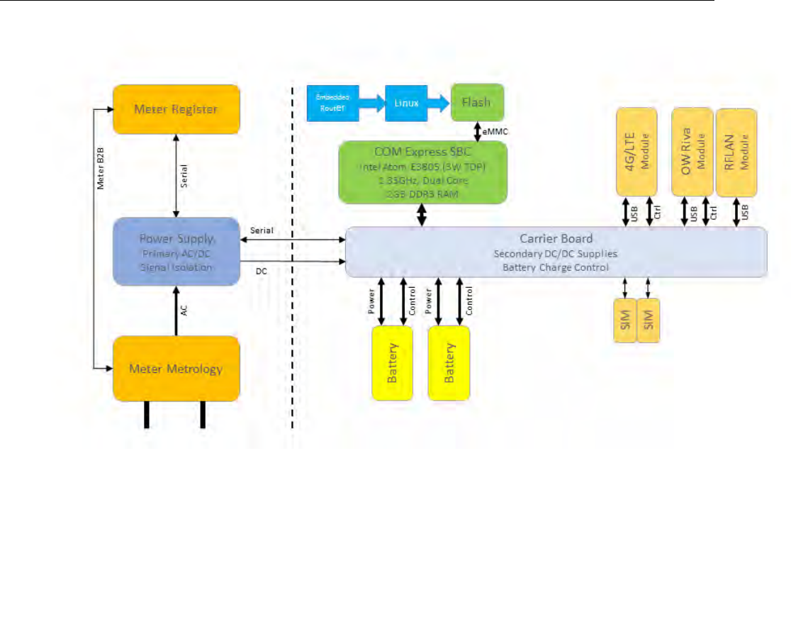
The Socket Based Router (SBR) is an OpenWay networking device whose software and
hardware are designed to route and forward information and to connect two or more logical
subnets (which do not necessarily map one-to-one to the physical interfaces of the router).
In other words, the SBR incorporates traditional router functionality in addition to relay
characteristics.
The Socket Based Router combines the existing cell relay functionality with the capability to
serve as an Internet Protocol (IP) network router. The SBR includes the capability to perform
the wrapping and unwrapping of the different IP versions. The SBR is a high capacity
OpenWay solution capable of simultaneous support of Wide Area Networks (WAN), Remote
Area Networks (RAN), and Local Area Networks (LAN).
The SBR provides dual-mesh network support by supporting both RFLAN and OpenWay
Riva mesh networks simultaneously while maintaining full cell relay functionality between
RFLAN meters. The SBR also improves OpenWay Riva mesh network by serving as a
gateway for distribution automation and adding new devices and applications such as
OpenWay Riva gas and water metering, streetlights, and future active grid applications
including Distributed Intelligence. Adaptive Communications Technology (ACT) for network
communications and distributed intelligence applications enables the SBR to support
various modulation rates with automatic selection of optimal data rates.
Using an independent base meter along with a specially designed router enclosure allows
the utility more flexibility with inventory management and field support. The SBR can be
serviced or replaced without disrupting meter service. The base meter remains in place
during field activities. The base meter uses a standard 2S form meter socket (either ring or
ringless).
Local access to the Socket Based Router is through secure Wifi. The Socket Based Router
is also accessible using SSH/Telnet through Port 22. Base meter local access is through
either zigbee or the optical port. Backhaul communications are with 4G/LTE cellular with
backward compatibility to 3G.
The Socket Based Router is designed with two field-replaceable battery packs that provide
up to 8 hours of hold-up time. In addition, these dual battery packs permit automated battery
health checks.
Architecture
TDC-xxxx-xxx DRAFT 4
Proprietary and Confidential
Packaging
The SBR is designed to deliver high performance in a variety of outdoor environments. SBR
packaging takes into consideration utility power meter attachment restrictions within the
allowed communications space parameters.
General
TDC-xxxx-xxx DRAFT 5
Proprietary and Confidential
Chapter 3 Physical Description
The Socket Based Router product is comprised of two primary hardware components: the
router with its housing and the base meter. When assembled the Socket Based Router
becomes one unit as shown
below.
TDC-xxxx-xxx DRAFT 6
Proprietary and Confidential

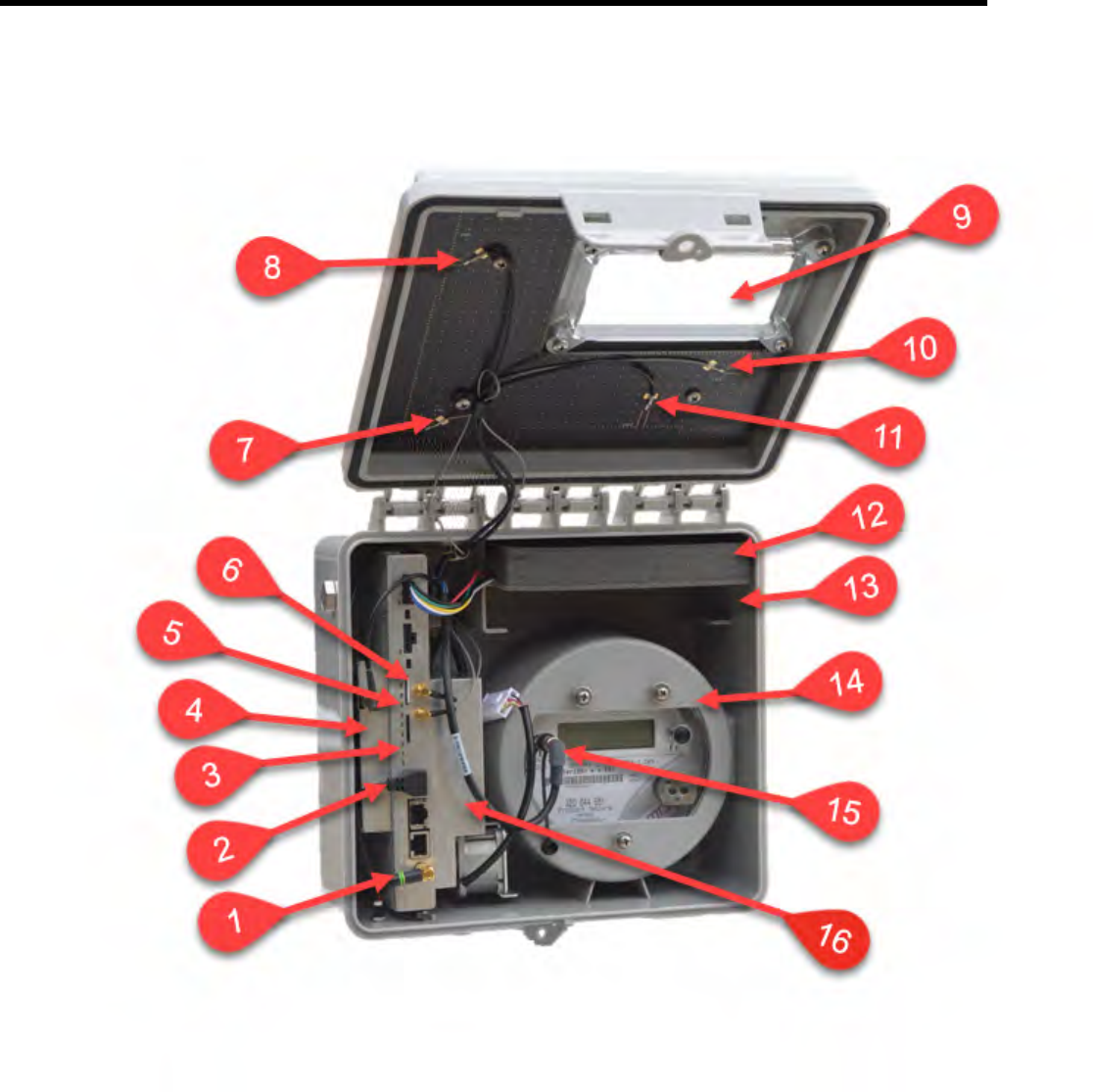
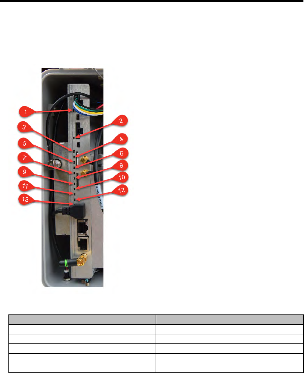
Table :
Callout Description
1 Monopod WiFi Antenna
2 RFLAN Connector
3 4G/LTE Module
4 RFLAN Module
5 LTE1 RF Connector
6 LTE2 RF Connector
7 LTE1 Antenna
8 RFLAN 900MHz Antenna
9 Viewing Window
10 LTE2 Antenna
11 OW Riva 900MHz CAM Antenna
12 Backup Battery
13 Additional Backup Battery Slot
14 Base Meter
15 Base Meter to Router Box Connector
16 OpenWay Riva Module
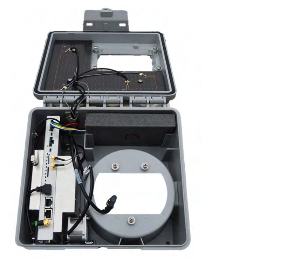
Router Box
The Socket Based Router enclosure is a weathertight box specially designed to protect the
router components and to attach a Base Meter. This Base Meter is a Form 2S meter that
has special lugs and a connector built into the outer cover for mounting the Router Box and
a connector to connect the Base Meter to the router.
Physical Description
TDC-xxxx-xxx DRAFT 7
Proprietary and Confidential
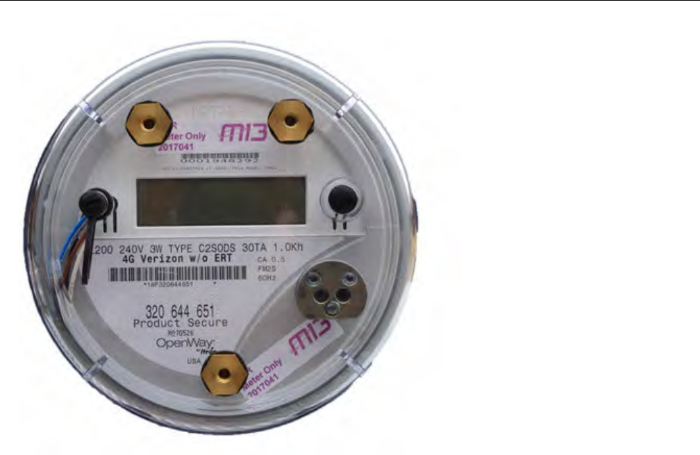
Base Meter
This Base Meter is a Form 2S meter that has special lugs built into the outer cover for
mounting the Router Box and a connector to connect the Base Meter to the router. The
Base meter is an ITRD device based on the HW3.5 OpenWay meter.
Physical Description
TDC-xxxx-xxx DRAFT 8
Proprietary and Confidential
Physical Description
TDC-xxxx-xxx DRAFT 9
Proprietary and Confidential
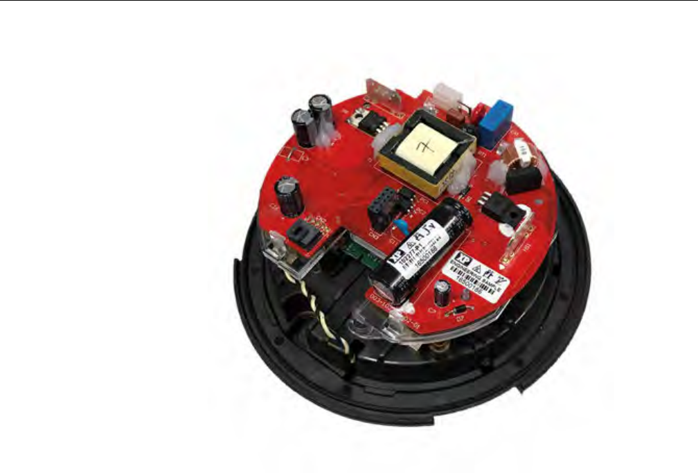
The Base Meter also includes a custom AC-DC primary power supply board with isolated
19V outputs. This provides serial port isolation and pass-through between the register and
the Socket Based Router.
Physical Description
TDC-xxxx-xxx DRAFT 10
Proprietary and Confidential

Chapter 4 Specifications
Operating Environment
Table :
Parameter Description
Temperature, Base Meter -40°C to +85°C (-40°F to +185°F)
Temperature, Modem -30°C to +65°C (-22°F to +149°F)
Humidity 0% to 95% non-condensing
Electrical
Table :
Parameter Description
Voltage Input 240 VAC (+/- 20% at 60 Hz) (+/- 10% at 50 Hz)
Frequency 60 Hz (50 Hz)
Burden (total burden for
meter and router)
14.7 Watts
Dimensions
Table : Router Box
Parameter Description
Height 10.8 inches (27.4cm)
Width 11 inches (30.0cm)
Depth 7.5 inches (19.1cm)
Table : Base Meter
Parameter Description
Height 6.95 inches (17.66cm)
Width 6.95 inches (17.66cm)
Depth 5.5 inches (13.97cm)
Shipping Weights
TDC-xxxx-xxx DRAFT 11
Proprietary and Confidential

Table : Router Box
Parameter Description
15 lbs(6.8 kg) 4 units with shipping carton
Table : Base Meter
Parameter Description
11 lbs (4.99kg) with battery and shipping box
Specifications
TDC-xxxx-xxx DRAFT 12
Proprietary and Confidential

Chapter 5 Installation
The Base Meter used with the Socket Based Router may be installed and powered up prior
to the installation of the Router Box. Base Meter installation must be compliant with the
generally accepted technical rules for the installation of electrical and telecommunication
equipment valid in your jurisdiction. This feature allows the Router Box to be installed,
serviced or exchanged without disrupting power to the residence.
Base Meter
Safety
Meter installation must be compliant with the generally accepted technical rules for the
installation of electrical and telecommunication equipment valid in your jurisdiction.
The electrical utility dictates the safety procedures for meter installations. Please check with
the local electrical utility for these safety procedures.
Install the meter in accordance with the voltage and current specifications printed on the
front panel and the wire and environmental specifications given in the installation
information.
Do not install the meter if it is damaged.
Do not install the meter if it has been dropped or otherwise subjected to significant impact
even if no damage can be seen.
Do not use the meter for primary protection purposes.
Unpacking and Inspection
Be sure you are working in a static-free environment; electrostatic discharge (ESD)
can damage meter components.
Upon receipt:
• Check the condition of the packaging to ensure there was no damage during shipment.
• Verify that the packaging label matches the order.
• Inspect for obvious damage to the cover, base, and meter assembly.
• Compare the meter and register nameplates to the record card and invoice. Verify the
type, class, voltage, form number, and other pertinent data.
• Verify that the Itron meter seals are in place.
As with all precision electronic instruments, the meter should be handled with care. Follow
these precautions when handling the meter:
TDC-xxxx-xxx DRAFT 13
Proprietary and Confidential

• Avoid damaging the meter base, cover, reset mechanism (if supplied), and optical
connector (if supplied).
• When handling modules, grip the circuit board by its edges. Do not touch the liquid
crystal display.
• Save the original packing materials.
Battery
The OpenWay Riva CENTRON meter contains a battery that powers the clock circuit during
a power outage. The battery is permanently soldered to the module and is expected to last
the life of the meter.
Caution: The product you have purchased contains a recyclable battery. At the end
of its useful life, under various state and local laws, it may be illegal to dispose of this
battery into the municipal waste stream. Check with your local area solid waste
officials for details about recycling options or proper disposal.
Selecting a Site
The meter is designed and manufactured to be installed in an environment with an
operating temperature range between -40°C and +85°C (-40°F to +185°F).
Router Box
Unpacking and Inspection
Upon receipt:
• Check the condition of the packaging to ensure there was no damage during shipment.
• Verify that the packaging label matches your order.
• Inspect for obvious damage to the device.
• Compare the nameplates to the record card and invoice. Verify the pertinent data.
• Verify that the unit seals are in place.
• Save the original packing materials.
Storage
Store the Socket Based Router in a clean, dry environment which meets the specifications
detailed in the Specifications chapter of this document. Avoid prolonged storage (more than
Installation
TDC-xxxx-xxx DRAFT 14
Proprietary and Confidential
one year) at temperatures above +70°C (+158°F). Store the unit in the original packing
material.
Selecting a Site
The Socket Based Router is intended for outdoor installation with an operating temperature
range between -40°C and +85°C (-40°F to +185°F). Operation in moderate temperatures
increases reliability and product life.
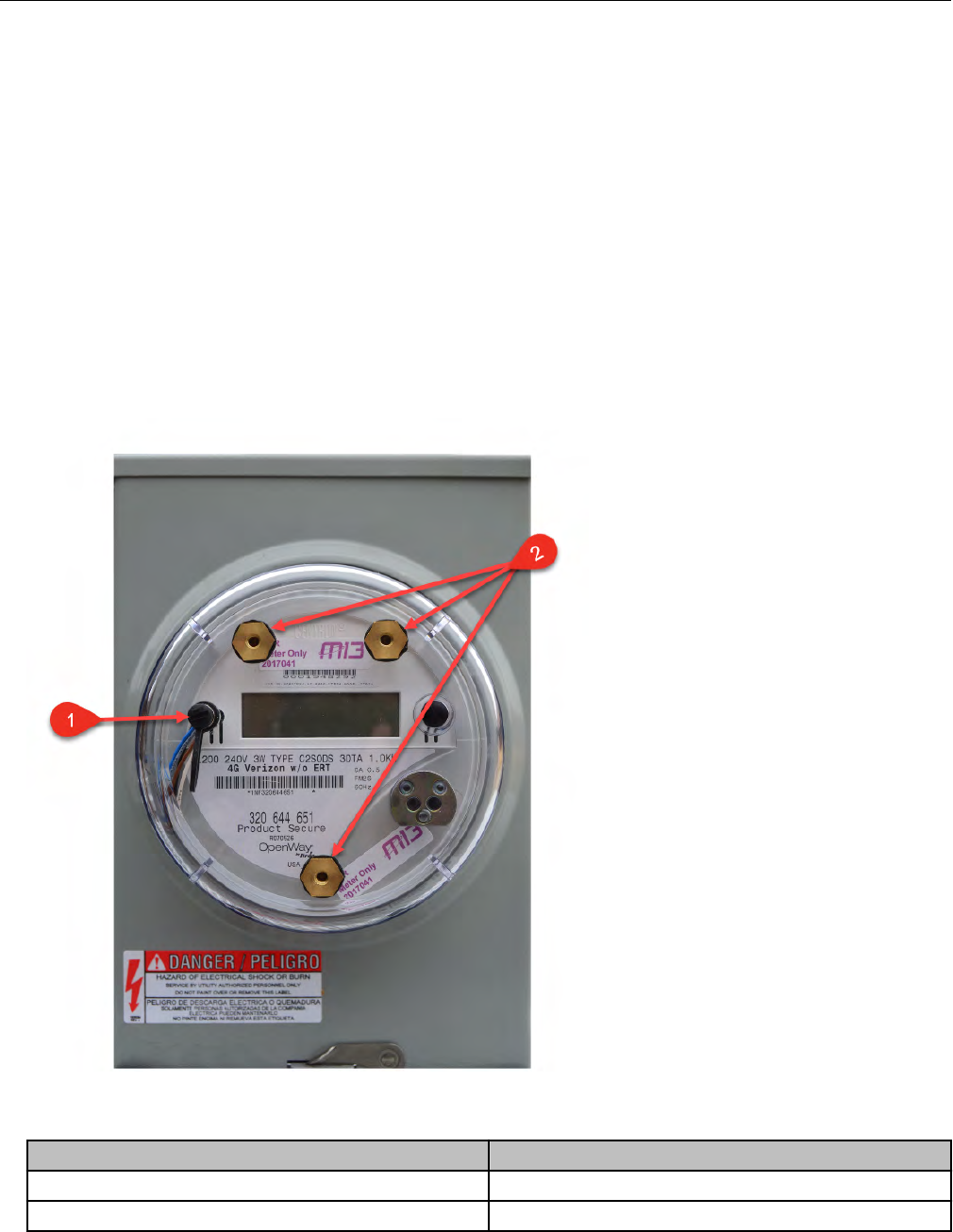
Mounting the Router Box to the Base Meter
The base meter is fitted with three threaded lugs on the outer cover to receive the three
screws that are captive to the router box. The outer cover also contains one electrical
connector for the router box cable.
Callout Description
1 Electrical connector
2 Screw mounting lugs
Installation
TDC-xxxx-xxx DRAFT 15
Proprietary and Confidential
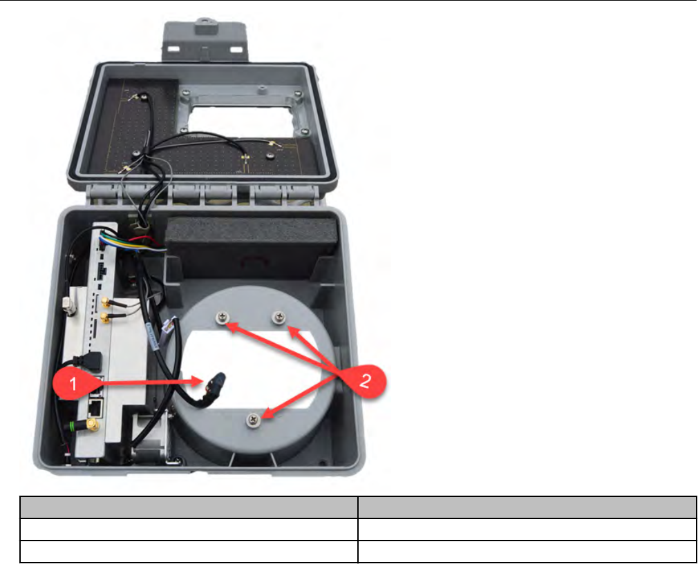
Callout Description
1 Router box connector cable
2 Captive mounting screws
Connecting the Router to the Base Meter
Insert the cable from the router into plug on the face of the base meter to make the electrical
connection between the router box and base meter.
Installation
TDC-xxxx-xxx DRAFT 16
Proprietary and Confidential

Installation
TDC-xxxx-xxx DRAFT 17
Proprietary and Confidential

Chapter 6 Configuration
Initial Setup
This section assumes that the SBR Customer configuration is not loaded by the factory. This
is meant for initial SBR Evaluation samples setup, only. For changes following initial setup,
use the HTTP interface with Advanced REST Client (ARC) tool in the Configuration and
Monitoring section.
Login
An SSH server is available for the user to connect to the SBR. To connect to the SBR using
WiFi setup a hotspot using the configured SSID/Password given with customer shipment
information. After which you can SSH into the SBR with the provision IP from the hotspot.
ior login via serial console. A serial console (UART0) is also enabled.
Table : Example
Ubuntu 16.04.3 LTS sbr-0-3-8 ttyS0
sbr-0-3-8 login:_
On both interfaces, the username isitron and the password is provided on customer
shipment information.
Table : Example
Last login: Fri Nov 10 13:18:33 EST 2017 from 172.17.212.30 on pts/1
Welcome to Ubuntu 16.04.3 LTS (GNU/Linux 4.10.0-37-generic x86_64)
* Documentation: https://help.ubuntu.com
* Management: https://landscape.canonical.com
* Support: https://ubuntu.com/advantage
48 packages can be updated.
23 updates are security updates.
itron@sbr-0-3-8:~$ _
SBR Configuration Script
The SBR includes a configuration script which allows the user the edit various configuration
variables. By default, it is in /home/itron/sbrconfig.sh and can only be run as root or
with sudo.
TDC-xxxx-xxx DRAFT 18
Proprietary and Confidential

Changing Hostname
To change the hostname, run sbrconfig script:
sudo ./sbrconfig.sh hostname <your hostname>
Table : Example
itron@sbr-0-3-8:~$ sudo ./sbrconfig.sh hostname sbr-test123-0-3-8
Parameter Count 2
Set the hostname of the SBR to sbr-test123-0-3-8
Parameter Count 1
hostname is set to sbr-test123-0-3-8
Reboot the SBR for the changes to be applied.
sudo reboot
C1222 Relay
The following c1222relayConfigure variables can be changed using the sbrconfig script.
i) SBR ESN
sudo ./sbrconfig.sh esn <your esn here>
Table : Example
itron@sbr-test123-0-3-8:~$ sudo ./sbrconfig.sh esn your.esn.here
Parameter Count 2
Set the Electronic Serial Number your.esn.here
Setting ESN to your.esn.here
ii) Collection Engine IP address
sudo ./sbrconfig.sh master_relay_address <CE IP address>
Table : Example
itron@sbr-test123-0-3-8:~$ sudo ./sbrconfig.sh master_relay_address your.master.relay.address
your.master.relay.address
Parameter Count 2
Set Master Relay Address your.master.relay.address
Setting master relay to your.master.relay.address
iii) Base Meter ESN
sudo ./sbrconfig.sh vcm_mac <BM ESN>
Configuration
TDC-xxxx-xxx DRAFT 19
Proprietary and Confidential

Table : Example
itron@sbr-test123-0-3-8:~$ sudo ./sbrconfig.sh vcm_mac 123456789
Parameter Count 2
Set the virtural comm MAC address to 123456789
VCM MAC to 123456789
RFLAN UID
sudo ./sbrconfig.sh utility_id <Utility ID>
Table : Example
itron@sbr-test123-0-3-8:~$ sudo ./sbrconfig.sh utility_id ff
Parameter Count 2
Set the Utility ID to ff
RFLAN COM UID set to ff
C1222 Relay Daemon PID 1611
SetUtilityID: OK
Modem Reset
Scheduled comm module reset. Takes about 1 minute to complete.
LTE Connection Manager
The following Connection Manager Configure variables can be changed using the sbrconfig
script.
i) APN
sudo ./sbrconfig.sh apn <cellular provider Access Point Name>
Table : Example
itron@sbr-test123-0-3-8:~$ sudo ./sbrconfig.sh apn your.apn.here
Parameter Count 2
Set the APN to your.apn.here
apn your.apn.here
System Configuration
The following System Configure variables can be changed using the sbrconfig script.
i) NTP Server
sudo ./sbrconfig.sh ntp_config <NTP Server IP address>
Configuration
TDC-xxxx-xxx DRAFT 20
Proprietary and Confidential

Table : Example
itron@sbr-test123-0-3-8:~$ sudo ./sbrconfig.sh ntp_config your.ntp.server
Parameter Count 2
NTP Configuration your.ntp.server
Setting NTP Server to your.ntp.server
ii) External Syslog Server
sudo ./sbrconfig.sh syslog_server <Syslog server IP address>
Table : Example
itron@sbr-test123-0-3-8:~$sudo ./sbrconfig.sh syslog_server your.syslog.server
Parameter Count 2
syslog Server Address your.syslog.server
Setting Syslog Server to your.syslog.server
Enabling Itron Service(s)
Enable mctrld
sudo systemctl enable mctrld
Start mctrld
sudo systemctl start mctrld
Table : Example
itron@sbr-test123-0-3-8:~$ sudo systemctl enable mctrld
mctrld.service is not a native service, redirecting to systemd-sysv-install
Executing /lib/systemd/systemd-sysv-install enable mctrld
itron@sbr-test123-0-3-8:~$ sudo systemctl start mctrld
The SBR will then connect to the LTE network and register to the CE. After this point, you
can use the HTTP interface with ARC for monitoring and to make any additional
configuration changes which are listed in the Configuration and Monitoring section.
Note: For certain configuration item(s) like SBR ESN, Base Meter ESN, APN, a system
reboot is required for the changes to take effect. This may be required after changing Test
Environments, if not handled by runtime configuration changes in the Configuration and
Monitoring section.
Configuration and Monitoring
The RESTful Web Services client, i.e. ARC, should only be used after Itron services have
been enabled and started as described in the SBR Configuration Script section.
Configuration
TDC-xxxx-xxx DRAFT 21
Proprietary and Confidential
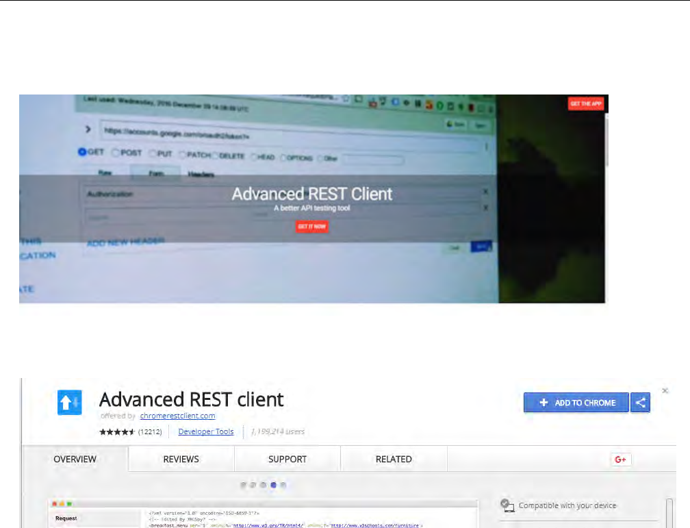
Installing Advanced REST Client Chrome Web App
a) https://advancedrestclient.com/
b) Hit the GET IT NOW or GET THE APP button the website and once redirected to the
chrome web store add it to chrome.
ARC Setup
Please, ensure HTTP “Content-Type” header is set to “application/json”, as shown below
before continuing.
Using ARC
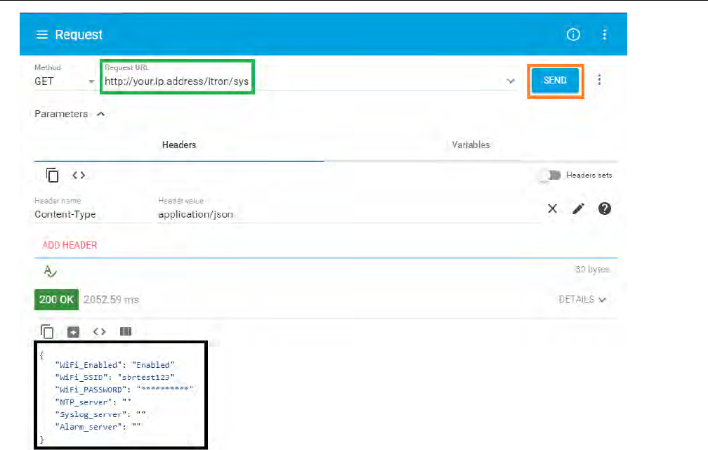
GET Request Using ARC
i) Enter the URL for the information you would like (green box) and hit the send button to the
right (orange box). The information (black box) will then be displayed.
Configuration
TDC-xxxx-xxx DRAFT 22
Proprietary and Confidential
PUT Request Using ARC
ii) Generally, you do a PUT request after a GET request this follows that logic.
iii) Enter IP address (green box).
iv) Select the Body tab (blue box) then ensure that Body content type is “application/json”
and Editor view is “Text input”.
v) Insert the option you wish to change (red box) using the same format as the output from
the GET request (black box). Ensuring that the text in the body is in the format:
{“option”:”option”}
vi) Once the change is formatted correctly you can hit send (orange box).
Configuration
TDC-xxxx-xxx DRAFT 23
Proprietary and Confidential
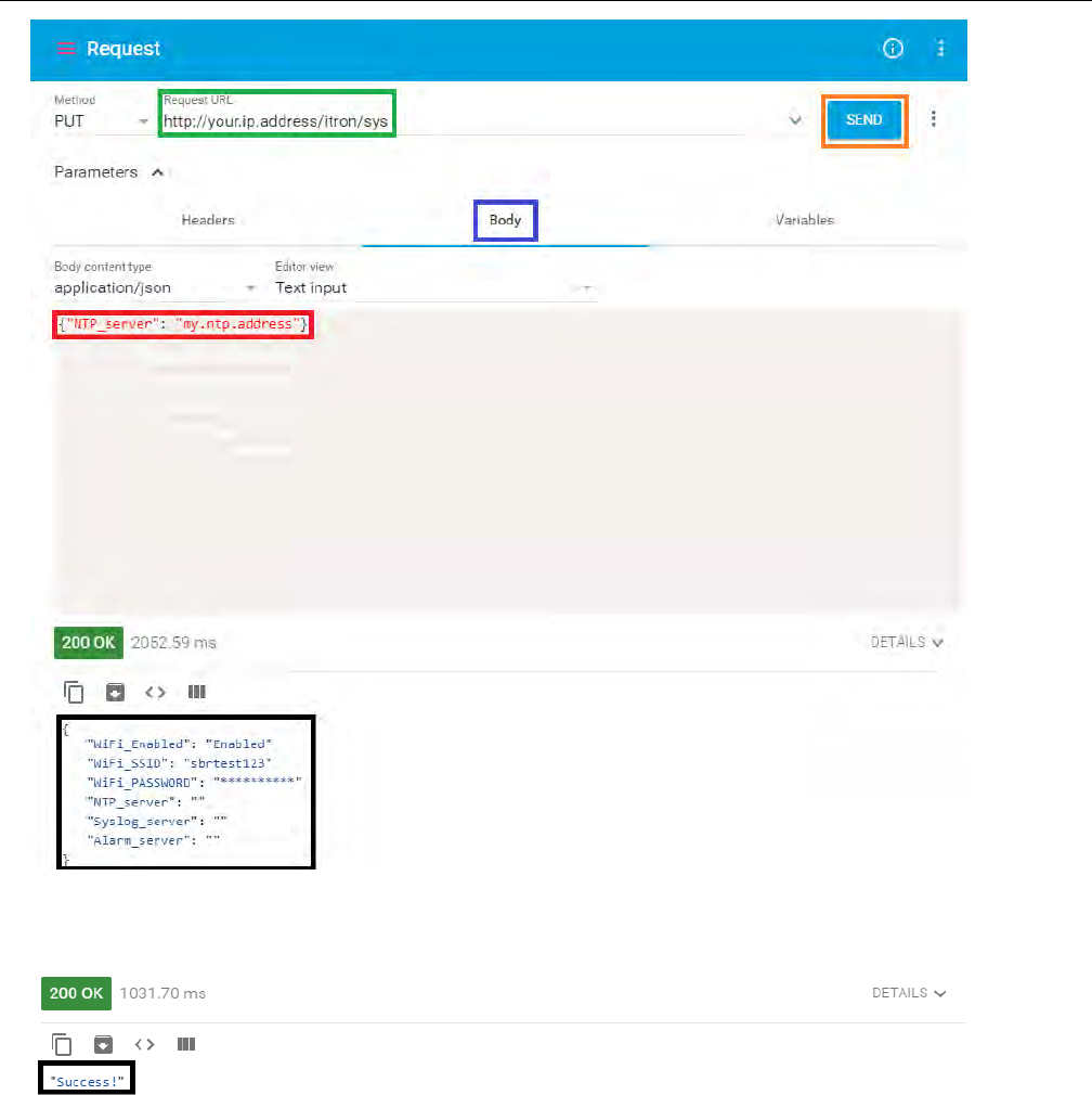
vii) After which point the output (black) will change to “Success!” if the put request was
successfully executed.
Changing Master Relay Address
i) Run a get request on http://your.ip.address/itron/c1222 to get current information on
C1222 Relay.
ii) To change the Master Relay Address, follow the same procedure as the used in the PUT
request example in the previous paragraph.
iii) Enter the information (red box) in the same layout as received by the GET request (black
box).
Configuration
TDC-xxxx-xxx DRAFT 24
Proprietary and Confidential
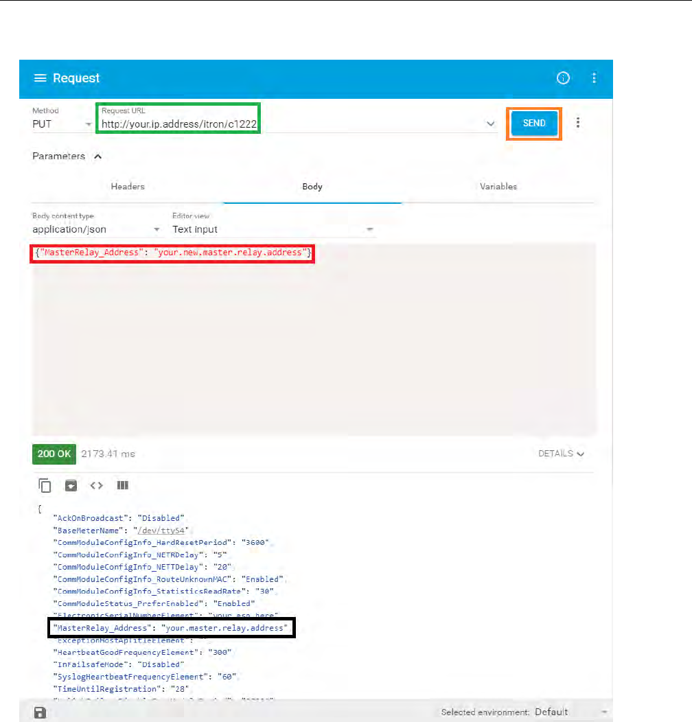
iv) After submitting the PUT request, you should see the "Success!" message if put request
was successfully executed.
Changing APN
You must use the Wifi interface to change the APN using ARC, as the cellular connection
drops when the APN is changed.
i) Run a GET request on http://your.wifi.ip.address/itron/modem to get current information
about the modem interface.
Configuration
TDC-xxxx-xxx DRAFT 25
Proprietary and Confidential
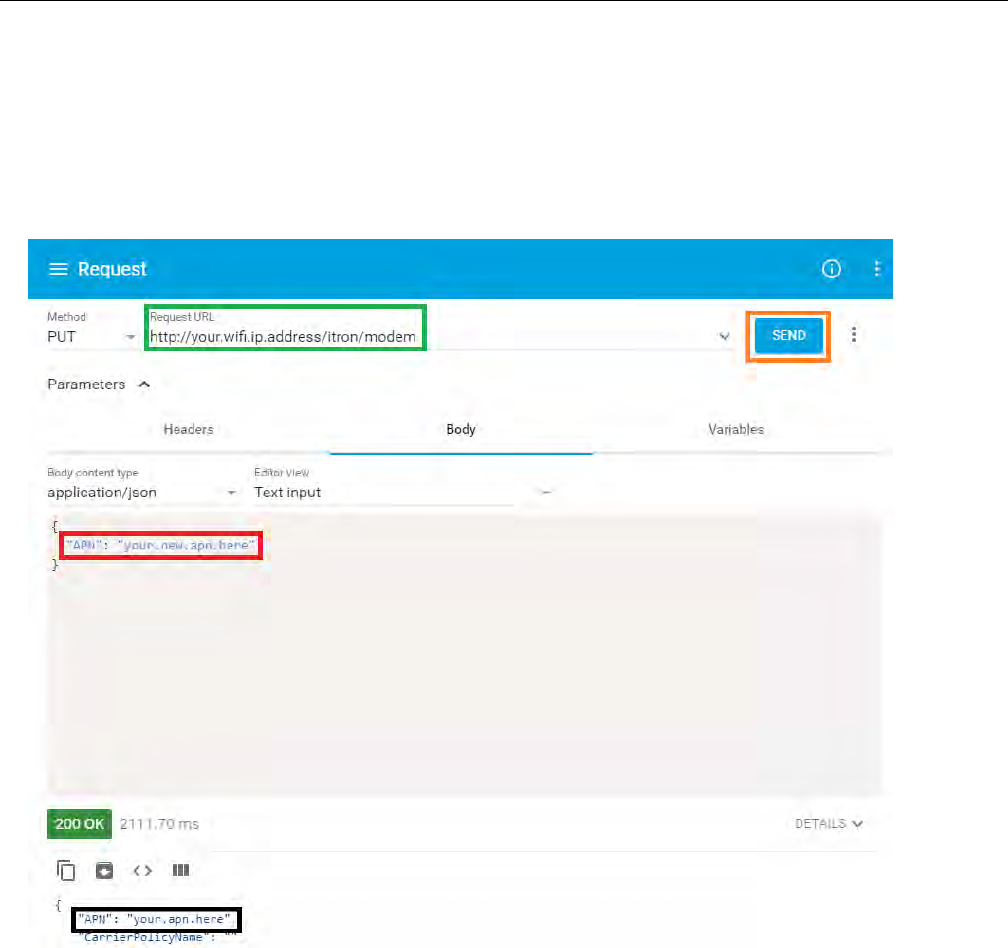
ii) To change APN, follow the same procedure as the used in the PUT request example.
iii) Enter the information (red box) in the same layout as received by the GET request (black
box).
iv) Submit Put request on the APN (orange box).
v) After submitting the PUT request, you should see the "Success!" message if put request
was successfully executed.
Reboot the SBR for the changes to be applied, doing so by SSHing into the SBR using the
wifi interface.
i) sudo reboot
Configuration
TDC-xxxx-xxx DRAFT 26
Proprietary and Confidential
Chapter 7 Operation
LEDs
The socket based router provides several LEDs to indicate the status of key elements in the
router.
Table : Router LED
Callout Description
1 Battery 1
2 Battery 2
3 DC In
4 System LED
5 Key E1
TDC-xxxx-xxx DRAFT 27
Proprietary and Confidential

Callout Description
6 Key E2
7 LTE
8 WiFi
9 Vcc USB
10 ACT Ready
11 HDD
12 Vcc 3.3V
13 Vcc 5V
System LED
The Socket Based Router contains two System LEDs: one internal to the router and one
located externally on the bottom left corner of the router box. The external LED provides a
view of the router status without the need to open the router box. The states of the external
LED mirror the states of the internal LED. The possible SYSLED states are
• Blink Red: C12.22 relay started, trying to establish a TCP connection to the CE
• Blink Green: TCP communication OK, registration with CE in progress
• Green: Registered with CE
• Red: Error (No CE communication, no backhaul, no RFLAN module…
Battery LED
The Socket Based Router contains two battery LEDs; one for each battery. If the Socket
Based Router is configured with either one or two batteries, the LED states are:
• Green: OK
• Alternate Green/Red (blink): Battery below warning capacity threshold
• Red: Battery below critical capacity threshold
If the Socket Based Router is configured with:
• only one battery the LED for the second battery LED will be in the off state.
• two batteries and one is missing, the corresponding LED will be in the red state
Events
All generated events are managed by the local syslog. This behavior cannot be changed. A
configuration item allows the events to duplicated and sent to a remote server:
syslog_server
Alarms
Operation
TDC-xxxx-xxx DRAFT 28
Proprietary and Confidential

Alarms are generated by Itron services. Itron Services monitor several parameters to ensure
the proper operation of the SBR. When an alarm is asserted, the services call a shell script:
sbr-alarm with an "alarm_on" parameter to signal the alarm. When an alarm is turned off,
the alarm script is also called with “alarm_off”. Every minute, if an alarm is still present, the
alarm script is called as a redundancy measure.
Discrimination of new alarms and redundancies is performed using an alarm counter that is
only incremented when an alarm is new. There is one alarm counter per alarm type.
Counters can be reset through the HTTPS API. The default behavior of the alarm script is
the following.
1. Log a generic message in the local syslog.
2. Perform one or several action(s) related to the specific alarm, if necessary.
Furthermore, a configuration item allows the generic events to be duplicated and sent to a
remote syslog server: alarm_server. This default behavior can be changed by modifying the
sbr-alarm script, without the need to rebuild the Itron binaries.
The alarm script syntax is the following:
sbr-alarm <alarm_name> <alarm_on|alarm_off> <value_or_state> <counter>
The generated events have the following characteristics:
• Priority:
o Alarm ON: daemon.warning
o Alarm OFF: daemon.notice
• Tag: sbr-alarm
• Value: Alarm: ON/OFF - Condition: <alarm_name> - Value: <value_or_state> - Count:
<counter>
Examples:
• sbr-alarm: Alarm: ON - Condition: battery_removed - Value: 2 - Count: 12
• sbr-alarm: Alarm: ON - Condition: door - Value: opened - Count: 25
• sbr-alarm: Alarm: OFF - Condition: door - Value: opened - Count: 25
List of Alarms
The following is a list of the alarms provided by the Socket Based Router.
• CPU Temp High
• CPU Temp Low
• Board Temp High
Operation
TDC-xxxx-xxx DRAFT 29
Proprietary and Confidential

• Board Temp Low
• Battery1 Capacity Critical (Charge %)
• Battery1 Capacity Warning (Charge %)
• Battery2 Capacity Critical (Charge %)
• Battery2 Capacity Warning (Charge %)
• Battery1 Temp High
• Battery1 Temp Low
• Battery2 Temp High
• Battery2 Temp Low
• AC Power (Present/ Absent)
• Door Status (Open/ Closed)
• Fan Speed Low
• Battery1 Removed (Inserted/ Removed)
• Battery2 Removed (Inserted/ Removed)
• LTE Connection (Lost/ Connected)
• LTE Signal Low
• Time Sync error
Operation
TDC-xxxx-xxx DRAFT 30
Proprietary and Confidential