Ives Architectural Hinges, Continuous Hinges And Pivots 105313
User Manual: Ives Architectural Hinges, Continuous Hinges and Pivots Literature
Open the PDF directly: View PDF ![]() .
.
Page Count: 164 [warning: Documents this large are best viewed by clicking the View PDF Link!]

Architectural
hardware
products

Ives Architectural hardware products
i

ii
Table of Contents
B
Pulls & Plates
A
Hinges & Pivots
C
Flush Bolts & Coordinators
D
Latches, Catches & Bolts
E
Stops
F
Exterior Hardware
G
Miscellaneous Hardware
page
Terms and Conditions ................................................iii-vi
Index by Product Description ........................................... vii
Index by Part Number ..................................................viii
Finish Chart .............................................................ix
Packaging, Handing .....................................................xi
A - Hinges and Pivots
Architectural Hinges ...............................................A2 - A11
Residential Hinges .....................................................A12
Continuous Hinges. . . . . . . . . . . . . . . . . . . . . . . . . . . . . . . . . . . . . . . . . . . . . . .A13 - A30
Pivots ...........................................................A31 - A49
Pocket Pivot/Hinges ..................................................A50
B - Pulls and Push Plates
Pull. . . . . . . . . . . . . . . . . . . . . . . . . . . . . . . . . . . . . . . . . . . . . . . . . . . . . . . . . . . . . . . . B2 - B8
Push Bars .........................................................B8 - B9
Vandal Resistant Trim ........................................... B10 - B12
Protection Plates .................................................B13 - B14
Mounting Detail ..................................................B15 - B17
C - Flush Bolts & Coordinators
Flush Bolts ........................................................C2 - C11
Coordinators .....................................................C12 - C16
D - Latches, Catches & Bolts
Surface Bolts ......................................................D2 - D6
Door Guards ............................................................D7
Roller Latches ....................................................D8 - D10
Angle Stops ........................................................... D11
Latches/Catches ................................................ D12 - D16
E - Stops
Floor Stops ........................................................ E2 - E5
Stops & Holders ...................................................E6 - E8
Wall Bumpers/Stops ............................................. E9 - E14
Wall Holders ..........................................................E15
Kick Down Holders ...............................................E16 - E17
Plunger Door Holders ..................................................E17
Roller Bumpers ........................................................E19
Residential Door Stops ..........................................E20 - E21
Hinge Pin Stops ................................................. E21 - E22
Silencers ..............................................................E23
F - Exterior Hardware
Lock Guards ....................................................... F2 - F4
Door Viewers ...................................................... F5 - F6
Door Knockers ..........................................................F7
Letter Box/Plates ......................................................F8
Door Numbers ..........................................................F9
Storm Door Latch ......................................................F9
Screen Door Pull .......................................................F10
Crash Stops ...........................................................F10
G - Miscellaneous Hardware
Hooks & Brackets ..................................................G2 - G6
Window Hardware .................................................G6 - G8
Hobby Hardware .................................................G9 - G12
Cabinet/Closet Hardware ........................................ G13 - G16
Ives Architectural hardware products

Ives Architectural hardware products
iii
Terms and Conditions
B
Pulls & Plates
A
Hinges & Pivots
C
Flush Bolts & Coordinators
D
Latches, Catches & Bolts
E
Stops
F
Exterior Hardware
G
Miscellaneous Hardware
1. GENERAL/ACCEPTANCE. (a) This Agreement contains the only terms and conditions
by which Company will quote and sell Deliverables to Customer; (b) The terms “purchase
order” or “order” for the purposes of this Agreement include the term “request for quotation,”
as appropriate; (c) This Agreement supersedes all pre-printed or boilerplate terms and
conditions set forth in any purchase order issued by Customer; (d) No reference herein to
Customer’s purchase order will in any way incorporate different or additional terms and
conditions, all of which Company hereby expressly objects to; (e) ANY ACCEPTANCE BY
COMPANY OF CUSTOMER’S PURCHASE ORDER IS EXPRESSLY CONDITIONED ON
THE CUSTOMER’S ASSENT TO AND ACCEPTANCE OF THE TERMS AND CONDITIONS
CONTAINED IN THIS AGREEMENT; (f) Company reserves the right to decline any order, in
whole or in part, for any reason.
2. ORDERS.
a. Order Processing. When Customer wishes to place an order for Deliverables, it will
deliver to Company a purchase order. All such purchase orders must (i) be in a written format
acceptable to Company, (ii) be legible, (iii) include a purchase order number, (iv) include
Customer’s account number, invoice address, ship to address, shipping method, shipper’s
letter of instruction for international shipments, part number, pricing, and designated contact
information, (v) include, if applicable, any special configuration ID numbers, necessary
programming information, special factory instructions, and requested specifications regarding
a particular finish, handing, design, backset, or strike, and (vi) reference any applicable pricing
discounts under an ongoing buying program or based on a written quote from Company,
along with the applicable buying program number or quotation number.
b. Minimum Orders. In the event the order value does not meet any required minimum
net Deliverable value, Company may, at its sole discretion, (i) increase the quantity of items
in the order to meet the minimum net Deliverable value requirement; (ii) apply a minimum
order charge; (iii) reject the order, or (iv) waive the requirement, provided that the waiver of
a requirement for one order shall not constitute a waiver of the requirement for any future
orders.
c. Acceptance of Purchase Orders. Company will endeavor to (i) acknowledge receipt
of each purchase order issued in accordance with this Agreement, and (ii) notify Customer
whether Company accepts or rejects the purchase order. If Company fails to accept or reject
a purchase order within a reasonable time period, such failure to respond will be deemed a
rejection of the entire order.
d. Changes to Order/ Cancellation of Orders. Additional terms and conditions regarding
order changes and cancellations are available on the Allegion customer website, WHICH
TERMS ARE EXPRESSLY INCORPORATED HEREIN BY REFERENCE. Unless otherwise
provided herein, Customer acknowledges that (i) requesting a Change Order may cause
a delay in the scheduled shipment date, a longer lead time or result in a new scheduled
shipment date; (ii) Orders may not be changed after 48 hours of Company’s order
acknowledgment; (iii) After 48 hours of Company’s order acknowledgment, all changes
to an accepted purchase order will be subject to a Change Order charge of 25% of the net
Deliverable value, plus the cost of labor and fabrication or raw material that Company
incurred prior to the receipt of the Change Order from Customer, or that may be required due
to the Change Order; (iv) the requested change may result in additional charges for labor,
fabrication, and raw material, and (v) if Customer cancels an order or portion of an order
that includes Deliverables that have been manufactured and prepped for shipping, a 35%
restocking fee will apply. Notwithstanding the foregoing, Customer cannot change or cancel
credential orders, reader orders, biometrics orders or any non-cataloged, special, Custom or
nonstandard items once they have been placed. All cancelled orders for a Non Recurring
Expense (NRE), credential orders, reader orders, biometrics orders, and/or Custom orders will
be subject to a cancellation charge of 100% of the acknowledged price.
e. Add-ons. Add-on orders will not be accepted. Additions to orders will be entered as
separate stand-alone orders and must qualify for all terms of sale, including discounts, on an
individual basis.
f. Fast-Track Orders. No changes or cancellations will be accepted on the 24-Hour
Fast Track Program. For 3-day Fast Track orders, changes and cancellations may only be
requested by Customer within 24 hours of Company’s order acknowledgment if the order has
not shipped. For 5-Day Fast Track orders, changes and cancellations may only be requested
by Customer if the order has not shipped and if the request is made to Company within
48 hours of Company’s order acknowledgment. Return Material Authorization (RMA) for
Deliverables must be processed through Fast Track Customer Service.
g. Steelcraft Orders. For all Steelcraft orders, changes or cancellations are allowed
without penalty only if made within 48 hours of Company’s order acknowledgment, and
provided that the order has not shipped. Some exceptions do apply – please consult the
factory. Changes are not allowed on Rapid Program orders after the order has been entered
and acknowledged. After 48 hours of Company’s order acknowledgment, all changes or
cancellations are subject to a charge of 25% of the order. Unless otherwise specified by
Company in writing, any changes to orders acknowledged by Company that affect the delivery
date will be deemed a new order and will require acknowledgement by Company as provided
in this Section. Additional products, features, terms and conditions regarding the Rapid
Program are available on the Allegion, WHICH TERMS ARE EXPRESSLY INCORPORATED
HEREIN BY REFERENCE.
3. PRICES, INVOICES AND PAYMENT.
a. Prices. The prices in Company’s Price Book are subject to change at any time, without
notice to Customer. Company may charge Customer additional amounts if Customer requests
special packing, marking, shipment, product modification, or engineering services. Oral prices
specified by Company are null and void. Quote numbers must be referenced on Customer’s
purchase order in order for the Company’s quoted pricing to apply. Orders that do not
reference a quote number will receive buy program pricing or book net pricing. Quoted prices
are for those specific products quoted for a specified job, and are subject to the Price Book in
effect at the time the quote was issued by Company.
b. Taxes. Prices do not include any present or future federal, state or local property,
license, privilege, sales, use, excise, gross receipts or other like taxes or assessments which
may result from transactions or any services performed in connection therewith. Any taxes,
charges, or duties imposed by any governmental authority on the sale of Deliverables will be
paid by Customer, in addition to the selling price specified by Company.
c. Payment Terms. Company will deliver to Customer an invoice with each shipment of
Deliverables hereunder. Customer will pay all invoiced amounts within 35 days of the invoice
date, provided that Customer may take a 2% discount if Customer pays in cash and Company
receives said payment within 20 days of the invoice date. For the avoidance of doubt, cash
discounts do not apply to credit card payments. Customer will make all payments in United
States dollars. Past due invoices will be subject to a late payment service charge of 1.5%
per month on any overdue unpaid balance, equivalent to 18% per annum, or the maximum
rate permitted by law, whichever is less. Customer shall reimburse Company for all costs of
collection, including, without limitation, reasonable attorneys’ fees, for any overdue amount
owed by Customer to Company, and such collection costs shall also be subject to interest
charges.
4. QUOTATIONS.
a. Project Quotations. Project or new construction quotes are restricted to the specific
project quoted for the quantities, finishes, and series of Deliverables referenced on the quote.
Company reserves the right to require proof of sale of Company products for any quoted
project.
b. Stock Quotations. Deliverables fulfilling stock quotations may only be used for the
following: i) Stocking of the Customer’s shelves for small, quick-turn, discretionary projects,
or ii) Sale to a general contractor or installer for new construction. Stock quotations may
not be used for any project containing any Company no-substitution, specified products.
Deliverables purchased under Stock Quotations cannot be redistributed to other Customer
branch locations or re-sold to other resellers or used for aftermarket sales, end-user annual
contracts or sold over the counter to any walk in trade.
c. General. All quotes are subject to this Agreement, unless otherwise specified by
Company, and are subject to change at any time prior to Company’s acceptance of a purchase
order referencing the applicable quote number. Company, its representatives and employees
reserve the right, in their sole discretion and for any reason, to refuse a Customer’s request
to quote a price other than the standard list price, regardless of whether Company or its
representatives or employees have previously quoted discounted prices to the Customer on
some or all of its orders. Customer’s failure to comply with this Section 4 will be considered
a material breach of this Agreement, and will entitle Company to immediately terminate any
purchase orders and/or Customer’s ability to distribute Company’s products.
5. SECURITY INTEREST. Customer grants Company, and Company retains, a purchase
money security interest and lien on any and all of Customer’s rights, title and interest in
each Deliverable sold by Company to Customer, wherever located, until the invoice for the
applicable Deliverable(s) is paid in full, including any late charges and costs of collection.
Customer authorizes Company to, and will assist Company in, taking all necessary steps to
perfect and maintain Company’s interest in such Deliverables.
6. CREDIT TERMS. Unless Customer pre-pays all of its purchase orders in advance, its
purchase orders will be subject to the credit limit and other terms of credit (“Credit Terms”)
set forth in Company’s credit application, which Credit Terms Customer acknowledges are
subject to change by Company at any time. Company reserves the right to request payment
in advance of shipment or any order or to request adequate assurances for Customer’s
payment of an order and may withhold or stop shipment, without any liability to Company,
until Customer submits payment or adequate assurance of payment.
7. RESALE OF DELIVERABLES. Customer agrees and warrants that it will offer Company
products in support of Company-written specifications and will maintain sufficient inventory
to adequately support End Users, installers, and/or general contractors’ needs. Customer
will adhere to any MSRP or resale pricing programs of Company. Failure to comply with this
provision will be considered a material breach of this Agreement, and will entitle Company to
immediately terminate any purchase order and/or Customer’s ability to distribute Company’s
products. Customer shall, at its own expense, gain and maintain sufficient knowledge of the
industry and products competitive with Deliverables so as to be able to (a) explain in detail to
End Users, installers, and/or general contractors the differences between the Deliverables and
competing products, (b) ensure that an adequate number of trained, capable and qualified
technical personnel with sufficient knowledge of the Deliverables and who have obtained all
necessary licenses and permits are available to assist End Users, installers, and/or general
contractors, and (c) respond to such End Users, installers, and/or general contractors with
respect to the general operation and use of the Deliverables including, but not limited to, (1)
acting as a liaison between the End Users, installers and/or general contractors and Company
in matters requiring Company participation, (2) providing general product information and
configuration support on standard protocols and features, (3) collecting relevant technical
problem identification information, and (4) posting and distributing any warranty information
concerning the Products in accordance with Company’s instructions. Customer is responsible
for all service and support resulting from the re-sale of any Deliverable to End-Users, installers
and/or general contractors, examples of which may include, but are not limited to, support
activities such as installation, initialization, software set-up, training, trouble-shooting,
technical support and field service. In the event Customer is unwilling or unable to perform
said support activities, Company reserves the right to recover from Customer any and all
expenses incurred by Company to resolve the afore-mentioned End-User, installer and/or
general contractor issues. Technical product training is recommended for Customer in order to
fully service and support Deliverables purchased from Company that are resold to End-Users,
installers and/or general contractors.
8. DEFAULT. If Customer is in default of payment or otherwise with respect to any purchase
order or other contract with Company, Company shall have the right, in addition to all other
legal remedies and without prejudice to any of its right hereunder, to defer further shipments
under that or any other purchase order until such default is corrected and to declare all
outstanding bills of Customer to be immediately due and payable.
9. INSPECTION AND DELIVERY.
a. Inspection. Customer will inspect all Deliverables immediately after receiving them.
Customer will be deemed to have accepted the Deliverables unless Customer notifies
Company in writing of any nonconformance within 10 days of delivery and provides Company
written evidence reasonably documenting that nonconformance. Inspection of Deliverables at
Company’s facility is not permitted.
b. Delivery. Delivery schedules for Deliverables are based upon current production
capacities, material or component availability, and inventory, and may be changed by
Company as conditions require. Delivery schedules for services are based upon Company’s
prompt receipt of, and prompt access to, Customer’s equipment and all information necessary
to complete the services. In no event will any delivery date be construed as falling within
the meaning of “time is of the essence.” Partial delivery shall be accepted by Customer and
paid for at the price and on the terms stated herein. Any partial delivery shall constitute a
separate sale, and payment shall be separately made when due. If any part of a delivery
hereunder is not delivered by Company in accordance with Customer’s purchase order, this
Agreement shall not be affected thereby.
10. TITLE & RISK OF LOSS. Unless otherwise specified by Company, (i) where the Customer
is located in the United States, all Deliverables will be sold “Uniform Commercial Code, FOB
Origin, Company’s factory”; and (ii) where the Customer is located outside of the United
States, all Products will be sold “Ex-works, Company’s factory (Incoterms 2010).” In either
instance, title and risk of loss will pass to Customer upon delivery to the carrier at Company’s

Ives Architectural hardware products iv
Terms and Conditions
B
Pulls & Plates
A
Hinges & Pivots
C
Flush Bolts & Coordinators
D
Latches, Catches & Bolts
E
Stops
F
Exterior Hardware
G
Miscellaneous Hardware
factory, provided, however, as set forth herein, Company shall retain a security interest in the
Deliverables until full payment has been made therefore, and Customer agrees, upon request,
to do all things and acts necessary to protect Company’s interest by adequately insuring
the Deliverables against loss or damage from any cause and to have Company named as
an additional insured. Customer will promptly provide Company with a copy of the relevant
certificate of insurance upon Company’s request.
11. SHIPPING & SHIPPING PROGRAMS.
a. Freight Charges. Company will ship all Deliverables in accordance with Company’s freight
shipment guidelines, which are set forth on the Allegion customer website (“Freight Shipping
Guidelines”), WHICH TERMS ARE EXPRESSLY INCORPORATED HEREIN.
b. Rush Charges. Expedited order options are available as set forth in Company’s freight
shipping guidelines.
c. Packing and Marking. Company will pack, mark, and ship Deliverables according to its
standard procedures for shipment, unless the parties agree, in writing, that Company will
comply with any special instructions provided by Customer. Special instructions may result in
an increased price.
d. International Shipments. For all international orders, a Shipper’s letter of instruction
must be submitted in writing with the order. Failure to do so will result in the order being
rejected. Complete adherence to this order requirement will be strictly enforced. Company
will not be held liable for any charges resulting from delays due to lack of complete required
information being supplied.
e. Once received by the Company, a purchase order cannot be combined with any other order
to qualify for freight allowances. In addition, Customer may not combine any Company brands
or product categories on a single order to meet the applicable net freight allowance, except
in the case of: i) FastTrack 24 Hour/5 Day Program, which is available for Schlage, Von Duprin,
LCN and Glynn-Johnson products; ii) FastTrack 24 Hour/3 Day Program, which is available for
Falcon Locks, Exits and Closers and Ives products. When an order includes products from the
brands listed in both (i) and (ii) above, the order will automatically default to the FastTrack
24 Hour/5 Day Program lead times and freight allowance.
12. CLAIMS. All claims must be submitted in writing to Company as follows: (i) All claims
for prices must be submitted within thirty (30) days from the date of invoice; (ii) All claims
regarding Deliverable quantity or incorrect orders must be submitted within ten (10) days from
the date of delivery; (iii) All claims for damage to Deliverables (while in the care, custody, and
control of Company) must be submitted within thirty (30) days from the date of invoice; (iv)
All claims for loss or damage to Deliverables while in the care, custody, and/or control of a
carrier will be the responsibility of Customer, unless otherwise agreed by the parties.
13. PRODUCT CHANGES. Company’s product policy is one of ongoing update and revision,
and accordingly, Company reserves the right to change, without notice, the design of, or the
process of manufacturing, the Deliverables covered by this Agreement.
14. PRODUCT USAGE LIMITATION. Customer agrees: (i) not to sell or use a Deliverable in
any manner contrary to the manner in which the Deliverable is intended to be used; and/or
(ii) not to modify the design of any Deliverable for use with another product without the prior
written consent of Company.
15. PRODUCT RETURNS. Unless otherwise agreed by the parties in writing, Deliverables
that are correctly furnished by Company per the purchase order may not be returned
unless Customer receives written authorization from Company. If returns are authorized
by Company, a return merchandise authorization (“RMA”) number must be provided by
Company. Deliverables identified under such RMA must be returned to Company within 90
days of issuance of the RMA. Such RMA number and any accompanying RMA documents, the
original invoice number, and a written explanation for the return must be included with the
returned Deliverables in order for Company to inspect and approve a credit for the return. For
warranty returns, a credit in the amount of the original purchase price will only be issued if,
after Company’s receipt and inspection of the returned Deliverables, Company confirms, in
its sole discretion, the defect is valid and approves the return. For non-warranty returns, (a)
in the event Company approves such a return, a credit will be made to Customer’s account
in the amount of the original purchase price less freight and a handling charge of 35% of
the net material on the original invoice; and (b) Only Deliverables that are new, current,
standard, non-obsolete, non-specially manufactured, unused, in their original condition as
at the time of sale by Company to Customer, in their original packaging and in Customer’s
inventory less than 180 days from the date of shipment by the Company may be considered by
Company for return. Such credit will only be issued if, after Company’s receipt and inspection
of Deliverables, Company approves the return. The amount of final credit will be determined
upon receipt at the factory and following Company’s inspection and analysis of the condition
of the returned material. Company retains the right to deny credit to anyone for any reason.
16. CONFIDENTIAL INFORMATION.
a. Non-Use And Non-Disclosure. Customer shall not use the Confidential Information of
the Company except for the purpose of performing its obligations under this Agreement or
exercising the rights granted herein (the “Purpose”). Customer shall protect Confidential
Information of the Company from disclosure and unauthorized use in the same manner that
it protects its own Confidential Information, but in no event shall such standard of care be
less than reasonable care. Customer may disclose Confidential Information of the Company
only to its employees who require such information for the Purpose and who are subject to
confidentiality obligations at least as protective as those set forth herein.
b. Proprietary Information and Advice. (a) All designs, data, and specifications provided by
Company are proprietary and may not be disclosed or reused by Customer without the prior
written consent of Company; (b) Company assumes no obligation or liability for any advice
given by Company, the results obtained, or damages incurred as a result of such advice, and all
such advice is given and accepted at Customer’s risk.
c. Return. Upon the termination or expiration of a purchase order or this Agreement or upon
the request of the Company, the Customer agrees to end all further use of, to immediately
return to the Company the original version of, and to delete or destroy all copies of, any and all
Confidential Information of the Company.
17. TRADEMARKS. Except as agreed to by Company in writing, Customer agrees not to (a)
use Company’s name in any form of publicity; or (b) use, create, register or market, directly or
indirectly, in whole or in part, Company’s names, logos, brands, or any other trademarks, or
names that are now or may hereafter be owned by Company, as part of Customer’s corporate
or business name, as part of an internet domain name, uniform resource locator (URL), or
in any way connected with Customer’s business, trade address or other designations. Upon
termination of this Agreement or upon the request of company for any reason, any use of
Company’s trademarks or names will be immediately discontinued.
18. LIMITED WARRANTY.
COMPANY MAKES NO OTHER WARRANTIES EXCEPT THOSE STATED IN
COMPANY’S LIMITED WARRANTY IN EFFECT ON THE DATE COMPANY
ACCEPTS EACH APPLICABLE PURCHASE ORDER (“LIMITED WARRANTY”).
THE LIMITED WARRANTY MAY BE FOUND IN THE APPLICABLE PRICE BOOK
AND ON THE ALLEGION CUSTOMER WEBSITE, WHICH TERMS ARE EXPRESSLY
INCORPORATED HEREIN BY REFERENCE. COMPANY WILL MAIL CUSTOMER A
HARD COPY OF THIS WARRANTY UPON CUSTOMER’S WRITTEN REQUEST. IN
THE EVENT THAT CERTAIN DELIVERABLE WARRANTIES ARE NOT FURNISHED
BY THE COMPANY TO CUSTOMER, COMPANY WARRANTS ONLY TO CUSTOMER
THAT THE DELIVERABLES WILL BE FREE FROM DEFECTS IN MATERIAL AND
WORKMANSHIP FOR A PERIOD OF 12 MONTHS FROM THE DATE OF SHIPMENT OF
THE DELIVERABLES. COMPANY’S SOLE OBLIGATION UNDER THIS WARRANTY IS
LIMITED TO REPAIRING OR REPLACING, AT COMPANY’S OPTION, THE DEFECTIVE
DELIVERABLE, PROVIDED WRITTEN NOTICE OF THE DEFECT OR NONCONFORMANCE
IS PROVIDED BY CUSTOMER WITHIN 30 DAYS OF DISCOVERY OF THE DEFECT OR
NONCONFORMANCE. COMPANY DISCLAIMS ALL OTHER WARRANTIES, EXPRESS
OR IMPLIED, WITH RESPECT TO THE DELIVERABLES, INCLUDING BUT NOT LIMITED
TO, ANY IMPLIED WARRANTIES OF NON-INFRINGEMENT, MERCHANTABILITY, OR
FITNESS FOR A PARTICULAR PURPOSE.
a. Exclusions. The provisions of this Limited Warranty do not apply to Deliverables that:
(A) are not the proper size for the application; (B) are not installed in accordance with
Company’s published installation instructions; (C) are installed with improper or incorrect
parts and/or are used for purposes for which they are not designed or intended; (D) have
been repaired or altered without the Company’s prior written consent; (E) have been
subjected to misuse, abuse, negligence or accident; (F) have been improperly stored, installed,
maintained or operated; (G) have been used in violation of written instructions provided by
Company to Customer; (H) have been subjected to improper temperature, humidity, or other
environmental conditions, or (I) have been affected by normal wear and tear. In addition,
the provisions of this Limited Warranty do not apply to any defects or issues with the design
or performance of equipment or products not manufactured by Company, nor does it apply
to any code compliance or permit requirements for the assembly, installation, erection or
construction of any goods. Company is not responsible for loss or damage resulting from
use of Deliverables in conjunction with parts or systems not manufactured by Company.
Accessories or products furnished by the Company, but manufactured by others, shall carry
whatever warranty the manufacturers have conveyed to the Company and which can be
passed to Customer.
b. Services. Company warrants that its services will be free from defects in material
and workmanship for a period of 12 months from the date of completion of the particular
items of service. Company’s sole obligation under this service warranty is limited to repair
or reperformance, at its option of the service, provided however, if repair or reperformance
is either impractical or impossible, the Company will refund to Customer that portion of the
price paid to Company for any defective service, provided written notice of the defect or
nonconformance is provided by Customer within 30 days of discovery of the nonconformance.
c. Notification. Customer agrees to immediately notify Company in writing if any claim is
made against Customer for any damages caused by any modules, parts, products, service or
other Deliverables which may be the direct result of any defect in the manufacture of such
aforementioned products. Customer agrees to cooperate with Company and its counsel in
the defense of such claim and Customer agrees not to settle such claim without Company’s
written consent. If Customer fails to notify Company of such claim or fails to cooperate in
such defense as aforesaid, then Company shall be discharged from any obligations under this
Section and shall have no further liability to Customer.
d. Exceptions. The following costs and expenses are not covered by the provisions of these
limited warranties: (i) labor costs for the removal and reinstallation of Deliverables or other
manufacturer’s products; (ii) shipping and freight expenses required to return Deliverables
to Company; (iii) normal maintenance; and (iv) economic losses. In addition, the provisions
of this warranty are not applicable to anything other than defects in Company’s material
(products only) or workmanship.
19. LIMITATION OF REMEDIES.
CUSTOMER’S EXCLUSIVE AND SOLE REMEDY ON ACCOUNT OF, OR IN RESPECT
OF, THE FURNISHING OF NON-CONFORMING DELIVERABLES, SHALL BE TO (A)
SECURE REPAIR OR REPLACEMENT OF THE PRODUCTS; OR (B) SECURE REPAIR
OR RE-PERFORMANCE OF THE SERVICES OR TO OBTAIN A REFUND OF THE
PRICE PAID FOR THE DEFECTIVE SERVICE, ALL AT COMPANY’S OPTION. IN NO
EVENT WILL THE COMPANY’S MAXIMUM LIABILITY EXCEED THE SELLING PRICE
FOR THE DELIVERABLE. THE WARRANTY, OBLIGATIONS AND LIABILITIES OF
COMPANY (INCLUDING ITS SUPPLIERS) AND THE RIGHTS AND REMEDIES OF
CUSTOMER ARE EXCLUSIVE AND ARE IN LIEU OF AND CUSTOMER HEREBY WAIVES
AND RELEASES ALL OTHER WARRANTIES, OBLIGATIONS, REPRESENTATIONS
OR LIABILITIES EXPRESS OR IMPLIED ARISING BY LAW, IN CONTRACT, TORT
(INCLUDING NEGLIGENCE OR STRICT LIABILITY) OR OTHERWISE, INCLUDING BUT
NOT LIMITED TO (I) ANY IMPLIED WARRANTY OF MERCHANTABILITY OR FITNESS
FOR A PARTICULAR PURPOSE OR ANY WARRANTY IMPLIED THROUGH COURSE
OF PERFORMANCE, COURSE OF DEALING, OR USAGE OF TRADE OR (II) CLAIMS
ARISING OUT OF THE NEGLIGENCE OF COMPANY OR COMPANY’S SUPPLIERS OR
(III) ANY OTHER CLAIM ARISING OUT OF, CONNECTED WITH, OR RESULTING FROM
THE PERFORMANCE OF COMPANY OR FROM THE DESIGN, MANUFACTURE, SALE,
REPAIR, LEASE OR USE OF THE DELIVERABLE, OR ANY COMPONENT THEREOF,
DELIVERED OR RENDERED HEREUNDER OR OTHERWISE.
20. INDEMNIFICATION AND LIMITATION OF LIABILITY. a. Customer shall indemnify,
defend and hold Company, and its officers, directors, employees, customers, Affiliates,
suppliers, users and agents, (collectively the “Indemnitees”) harmless from and against any
and all damages, claims, losses, expenses, costs, obligations, liabilities, including without
limiting the generality of the foregoing, liabilities for court costs and attorneys’ fees, suffered
directly or indirectly by an Indemnitee by reason of, or arising out of any injury, death or loss to
any person, or injury to any property (collectively, “Damages”), received
or sustained by any person(s) or property, arising out of, occasioned by, attributable or related
to i) any breach of any representation or warranty made by Customer, its officers, directors,
employees, affiliates, users, agents, representatives or customers to Company or any third
party, (ii) any failure by Customer to perform or fulfill any of its covenants, acts and/or
omissions to Company or to any third party, or (iii) any litigation, proceeding or claim by any
third party relating in any way to the obligations of Customer and/or the Deliverables sold by
Company to Customer hereunder. Customer shall not consummate any settlement of any
indemnified claim without the Indemnitees’ prior written consent. Customer’s obligation to

Ives Architectural hardware products
B
Pulls & Plates
A
Hinges & Pivots
C
Flush Bolts & Coordinators
D
Latches, Catches & Bolts
E
Stops
F
Exterior Hardware
G
Miscellaneous Hardware
indemnify Indemnitees will continue in full force and effect notwithstanding the termination
or expiration of any order under this Agreement. In any claim against an Indemnitee by an
employee of Customer or any subcontractor or anyone directly or indirectly employed by any
of them or anyone for whose acts they may be liable, the indemnification obligations set
forth in this Section shall not be limited in any way by or for Customer or any subcontractor
under any applicable worker’s compensation act, disability or other employee benefit act.
This provision shall survive termination of any order or Agreement. IN NO EVENT WILL
COMPANY, ITS OFFICERS, DIRECTORS, EMPLOYEES, CUSTOMERS, AFFILIATES,
USERS AND AGENTS, (NOR COMPANY’S SUPPLIERS) BE LIABLE FOR ANY
INCIDENTAL, CONSEQUENTIAL, INDIRECT, SPECIAL, OR PUNITIVE DAMAGES OF
ANY KIND OR NATURE UNDER ANY CIRCUMSTANCES INCLUDING, BUT NOT LIMITED
TO, LOSS OF USE OF THE PRODUCTS, SERVICE INTERRUPTION, LOSS OF PROFITS,
LOSS OF REVENUE, LOSS OF INTEREST, LOST GOODWILL, LOSS OF DATA, WORK
STOPPAGE, IMPAIRMENT OF OTHER GOODS, LOSS BY REASON OF SHUTDOWN
OR NON-OPERATION, INCREASED EXPENSES OF OPERATION, OR CLAIMS OF
CUSTOMER’S CUSTOMERS, OR ANY OTHER LOSSES OR DAMAGES ARISING
OUT OF ANY LACK OR LOSS OF USE OF THE DELIVERABLES WHETHER BASED
ON CONTRACT, WARRANTY, TORT (INCLUDING, BUT NOT LIMITED TO, STRICT
LIABILITY OR NEGLIGENCE), PATENT INFRINGEMENT, OR OTHERWISE, EVEN IF
ADVISED OF THE POSSIBILITY OF SUCH DAMAGES.
b) INTELLECTUAL PROPERTY INDEMNITY. Company makes no representation or
warranty to the Customer that the Deliverables shall not infringe any intellectual property
rights including, without limitations, claims arising from patent, copyright, trademark, trade
secret, or other intellectual property infringement. Customer agrees to hold Company
harmless from and defend the Company against any such claim of intellectual property
infringement, including any Damages resulting from that claim, the cost of complying
with any preliminary or permanent injunction, and all other costs of defense (including the
attorneys’ fees and costs), in connection with the foregoing.
c) To the extent that applicable law does not permit any limitations set out in this
Agreement, such limitation shall not be applied or invoked. Nothing in this Agreement will
be interpreted to disclaim liability of Company or the Indemnitees for gross negligence or
willful misconduct. The limitations of remedy and liability herein shall not be interpreted to
affect Company’s obligations, if any, for claims for (i) property damage, (ii) personal injury,
or (iii) wrongful death asserted by persons who are not parties to or beneficiaries of this
Agreement. Further, the limitations of remedy and liability herein shall not be interpreted
to limit Company’s or Customer’s right, if permitted by applicable law, to assert a claim for
contribution among joint tortfeasors in connection with a claim by a person who is not a party
to this Agreement.
21. CERTIFICATIONS. Certification of Deliverables for compliance with UL and ANSI
standards are tested and performed by third-party independent laboratories. Any field
modification or alteration of certified Deliverables will void certification and Company is not
liable to Customer to certify any modified or altered Deliverable.
22. TERM FOR CLAIMS. NO ACTION ARISING OUT OF ANY CLAIMED BREACH OF THIS
AGREEMENT BY COMPANY MAY BE BROUGHT BY CUSTOMER MORE THAN ONE (1)
YEAR AFTER THE CAUSE OF ACTION HAS ARISEN.
23. CONSUMER PRODUCTS
WITH RESPECT TO “CONSUMER PRODUCTS” AS DEFINED UNDER THE MAGNUSON-
MOSS WARRANTY ACT (“MMWA”), THE FOLLOWING STATEMENTS ARE MADE. (A)
SOME STATES OR LOCAL LAWS DO NOT ALLOW LIMITATIONS ON HOW LONG AN
IMPLIED WARRANTY LASTS, SO THE ABOVE LIMITATION MAY NOT APPLY TO YOU;
(B) IF ANY IMPLIED WARRANTY IS PROVIDED UNDER THE MMWA, IT IS LIMITED
TO THE DURATION OF THE WARRANTY PROVIDED IN SECTION 18 ABOVE. (C)
SOME STATES OR LOCAL LAWS DO NOT ALLOW THE EXCLUSION OR LIMITATION
OF INCIDENTAL OR CONSEQUENTIAL DAMAGES, SO THE ABOVE LIMITATION
OR EXCLUSION MAY NOT APPLY TO YOU; AND (D) THIS WARRANTY GIVES YOU
SPECIFIC LEGAL RIGHTS AND YOU MAY ALSO HAVE OTHER RIGHTS WHICH VARY
FROM STATE TO STATE OR LOCATION TO LOCATION.
24. FORCE MAJEURE/EXCUSABLE DELAY. Any delay or failure of Company to perform its
obligations hereunder will be excused to the extent that it is caused by an event or occurrence
beyond Company’s control such as, by way of example and not by way of limitation, acts
of God, acts by any governmental authority (whether valid or invalid), governmental laws
and regulations not presently in effect, fires, floods, windstorms, explosions, riots, natural
disasters, wars, sabotage, accidents, labor problems (including, without limitation, lockouts,
strikes, and slowdowns) at Company’s facility, its source plant or their suppliers, inability
to obtain power, material, labor equipment, or transportation, or court injunction or order.
The delivery date will be extended for a time equal to that of the delay and the schedule for
Company’s performance will be deemed adjusted to that effect.
25. ENTIRE AGREEMENT AND AMENDMENT. This Agreement, together with the
attachments, exhibits, webpages, or supplements specifically referenced and incorporated
herein, constitute the entire agreement between Company and Customer with respect to
the matters contained herein and supersede all previous communications, representations,
or agreements, either oral or written between Company and Customer. No agreement or
understanding varying or expanding this Agreement will be binding upon either party unless it
is in writing and signed by a duly authorized representative of each party hereto.
26. CONFLICTS. In the event of any conflict or inconsistency between the terms of any
agreement, or any part of an agreement or the various documents (including, but not
limited to, electronic documents) between Company and Customer, unless the parties
agree otherwise in writing, the various components of the agreements shall be given the
following precedence (in descending order of precedence): a) any master agreement or long
term agreement between Company and Customer; b) any specific terms, conditions and/
or warranties of the individual products or Deliverables; c) the terms and conditions of this
Agreement, and d) any purchase order.
27. UNSATISFACTORY CREDIT/TERMINATION FOR INSOLVENCY OR DEFAULT.
Customer shall furnish Company with statements evidencing Customer’s financial condition
as Company may, from time to time, reasonably request, and shall notify Company
immediately of any and all events that may have a material adverse effect on Customer’s
business or financial condition. If Company determines, in its sole discretion, that Customer’s
financial condition or creditworthiness is inadequate or unsatisfactory, then in addition to
Company’s other rights, Company may without liability or penalty, take any of the following
actions: (i) modify the payment terms for any outstanding and/or future purchases; (ii) cancel
any previously accepted orders; (iii) delay any further shipment of Deliverables to Customer;
or (iv) any combination of the above.
Company may immediately terminate an order from Customer by giving written notice to
Customer in the event of the happening of any of the following or any other comparable
event: (i) insolvency of the Customer; (ii) filing of a petition in bankruptcy by or against the
Customer; (iii) appointment of a receiver or trustee for the Customer; (iv) execution of an
assignment for the benefit of creditors by the Customer, all of which will allow Company to
demand reclamation of all affected orders; (v) Customer ceases or threatens to cease to
trade; (vi) Company determines that Customer does not meet or no longer meets the credit
requirements of Company or Customer’s credit account is closed; (vii) any Customer violation
of law, specifically including, without limitation, those laws set forth in this Agreement.
In the event of termination in accordance with this section, Company will not be obligated
to accept any existing or additional orders from Customer and Company will be released
from its obligation to deliver under orders accepted prior to such termination. The rejection
or termination of any order by Company will not entitle Customer to any termination or
severance compensation, or to any payment in respect to any goodwill established by
Customer, or render Company liable for damages on account of the loss of prospective
profits, or on account of any loss, expenditure, investment or obligation incurred or made by
Customer.
No action taken under this Section 27 by Company (nor any failure of Company to act under
this Section 27) will constitute a waiver by Company of any of its rights to enforce Customer’s
obligations, including the obligation of Customer to make payments as required under this
Agreement. Upon termination of any order, all amounts owed by Customer to Company will
become immediately due and payable, whether or not otherwise then due or payable.
28. CREDIT RISK ON RESALE OF DELIVERABLES. Customer is responsible for all credit
risks with respect to, and for collecting payment for, all Deliverables sold to third parties
(including End Users, installers, and/or general contractors) whether or not Customer has
made full payment to Company for such Deliverables. The inability of Customer to collect
payment for any Deliverable shall not affect Customer’s obligation to pay Company for any
Deliverable.
29. GOVERNING LAW; VENUE; AND EXPENSES. Any dispute or claim relating to this
Agreement shall be governed by and construed according to the laws of the State of Indiana
(excluding its conflict of laws principles); and not by the provisions of the 1980 United Nations
Convention on the International Sale of Goods. Any disputes or claims shall be instituted
and maintained in the courts of the State of Indiana. Customer consents to the exercise of
jurisdiction over it by such courts and agrees that Indiana is not an inconvenient forum for any
action arising from or relating to this Agreement. Customer agrees to pay for all expenses
(including, but not limited to, collection costs, court costs and attorneys’ fees) incurred by
Company in enforcing the obligations of Customer under this Agreement.
30. RELATIONSHIP OF THE PARTIES. Nothing in this Agreement or any other document
creates an employment, partnership, joint venture, or agency relationship between Company
and Customer, including that of franchisee/franchisor. No party will have any power or
authority to enter into any commitment on behalf of or otherwise bind the any other party
on any matter. No employee of Customer will be deemed to be an employee of Company.
If any provision of this Agreement is deemed to create a franchise relationship or business
opportunity between the Parties, then Company may terminate any purchase order or this
Agreement or the Parties shall negotiate in good faith to modify this Agreement so as to
effect the original intent of the Parties as closely as possible in a mutually acceptable manner
in order that the transactions contemplated hereby are consummated as a reseller agreement
and not a franchise or business opportunity agreement.
31. SETOFF. Customer does not have the right to setoff or to back charge against any
amounts which become payable to Company under this Agreement or otherwise. Company
will not accept responsibility for backcharges for the cost of material or labor by Customer or
any third party.
32. ELECTRONIC COMMUNICATIONS AND ELECTRONIC SIGNATURES. Both parties
expressly agree to electronic transactions and acknowledge that documents they sign
electronically will bind them to the same extent as a paper signature. Customer represents
and warrants to Company that only employees authorized to bind Customer legally shall
electronically sign any document under this Agreement. Customer shall comply with any
method of electronic communication/payment processing specified by Company, including
electronic funds transfer, pay-on-receipt processes/systems, order transmission, releases,
electronic signature, and electronic communication systems, including, without limitation, the
use of electronic data interchange (“EDI”) portals. Notwithstanding the foregoing, e-mails,
even those containing a signature block of one of Company’s representatives, shall not
constitute a signed writing.
33. COMPLIANCE WITH APPLICABLE LAWS.
a. General. Company and Customer will comply with all applicable federal, state and
municipal laws, regulations, codes, ordinances and orders that pertain to the Deliverables,
including but not limited to full compliance with any applicable provisions of The Health
Insurance Portability and Accountability Act. Where the Customer is located outside the
United States, or where the customer intends to ship the product outside the United States,
the Customer shall be responsible for compliance with all U.S. export laws, and for filing all
U.S. Electronic Export Information, as applicable.
b. The Customer acknowledges and agrees that: (i) it shall not violate applicable laws
and regulations in performing its duties under this Agreement; (ii) it does not and shall not
engage in any conduct that shall violate any applicable anti-bribery or anti-corruption laws
or regulations; (iii) it (and its owners, officers, directors, employees and agents) shall not
pay, offer, promise or authorize the payment of, either directly or indirectly, anything of value
(including but not limited to cash, gifts and entertainment) to (a) any government official
or employee of any government; (b) any official or employee of any department, agency, or
instrumentality of a government; (c) any employee of any corporation or entity owned or
controlled by a government; (d) any family member of such officials or employees; (e) any
political party, party official, or political candidate; or (f) any other persons, owners, officers,
directors, employees and agents of any corporation or entity; to improperly or illegally assist
in obtaining or retaining business (including but not limited to any contracts, avoidance
of duties or reduction of tariffs, reduction of taxes or to obtain money owed, or to obtain
regulatory approval) or for the purpose of causing, soliciting or inducing the sale and purchase
of the Deliverables by any party, and (iv) it has full knowledge of and will comply with the
Terms and Conditions
v

Ives Architectural hardware products
B
Pulls & Plates
A
Hinges & Pivots
C
Flush Bolts & Coordinators
D
Latches, Catches & Bolts
E
Stops
F
Exterior Hardware
G
Miscellaneous Hardware
Company’s Code of Conduct for Business Partners as set forth on the Allegion customer
website, WHICH IS HEREBY INCORPORATED BY REFERENCE.
c. The Customer shall indemnify and hold the Company harmless from any claim, demand,
expense or cost arising from any breach of this Article.
d. The Customer shall permit the Company to conduct an audit or review of the Customer’s
financial books and records and business operations at such other times that the Company
considers it necessary to confirm compliance with this provision. Such audit may be conducted
by representatives of the Company or, at the Company’s sole discretion, by a certified public
accounting firm selected by the Company. The Customer shall cooperate with any inquiries
from the Company’s Ethics & Compliance Group.
e. A violation of this provision constitutes a material breach of this Agreement and the
Company may terminate any purchase order or this Agreement immediately, with no
opportunity to cure, in accordance with Section 27 of this Agreement.
f. Notwithstanding the foregoing provisions of this Section 33, (i) Company is not responsible
for obtaining or maintaining any permits for the performance of services or the verification
or compliance with any code requirements relative to the performance of services, (ii) to the
extent any sale of Deliverables pursuant to this Agreement may require approval of the U.S.
Government, Company’s obligations under this Agreement are conditioned upon the grant of
such approval and upon compliance by Customer with any restrictions imposed by the U.S.
Government in connection with such approval, and (iii) in the event the Deliverables are to
be used in a nuclear facility, the Customer shall, prior to such use, arrange for insurance or
governmental indemnity protecting Company against liability. The Customer hereby releases
and agrees to indemnify Company and its suppliers for any nuclear damage including, but not
limited to, loss of use, in any manner arising out of the nuclear incident, whether alleged to be
due, in whole or in part by Company or its suppliers.
g. No Inducements. Each party represents to each other that neither it nor any person
acting on its behalf has, in contravention of any applicable law, given or offered to give or will
give or offer to give, any sum of money or other material consideration to any person, directly
or indirectly, as an inducement to obtain business hereunder or to influence the granting
of licenses or other governmental permissions to enter into this Agreement or perform
obligations hereunder.
h. Equal Employment Opportunity. Company is a U.S. federal contractor that complies with
Executive Order 11246, as amended, and applicable regulations in 41 CFR Parts 60-1 through
60-60, 29 U.S.C. § 793 and applicable regulations in 41 CFR § 60-741; and 38 U.S.C. § 4212 and
applicable regulations in 41 CFR Part 60-250 and 60-300. THE FOLLOWING PROVISIONS
ARE INCORPORATED HEREIN BY REFERENCE: Executive Order 11246 and 41 CFR §
60-4.3(a); Executive Order 11701 and 41 CFR §§ 60-250.5(a), 60-300.5; Executive Order 11758
and 41 CFR § 60-741.5(a); U.S. immigration laws, including the L-1 Visa Reform Act of 2004
and the H-1B Visa Reform Act of 2004; and Executive Order 13496.
i. Ethical Business Conduct. Customer shall adopt and comply with Company’s Business
Partner Code of Conduct which is EXPRESSLY INCORPORATED HEREIN BY REFERENCE.
34. REPRESENTATIONS AND WARRANTIES. Customer represents, warrants and
covenants to Company that: (a) it has the right, power, and authority to enter into this
Agreement and fully perform its obligations hereunder; (b) it has all necessary rights in and
to its respective Content and Marks for use within the scope of this Agreement, including
the licenses granted herein; and (c) it complies, and at all times shall comply, with all laws,
rules, and regulations in effect that are applicable to its performance under this Agreement,
including obtaining all such approvals and/or permits as may be required hereunder.
35. NO THIRD-PARTY BENEFICIARY. Each party is entering into this Agreement solely
based on the representations contained herein for its own purposes and not for the benefit of
any third party.
36. NOTICES AND CHANGE OF ADDRESS. All notices or other communications under this
Agreement shall be in writing and delivered in person, or sent by receipted courier, express
mail, e-mail, or postage prepaid certified or registered mail, addressed to the party for whom it
is intended, at the addresses set forth in this Agreement. Either party may change its address
for notice by giving written notice to the other party. Any notice or other communication shall
be deemed given no later than the date actually received. Notice by courier, express mail,
certified mail, or registered mail shall be deemed given on the date it is officially recorded as
delivered and, in the absence of such record of delivery, it shall be rebuttably presumed to
have been delivered on the third Business Day after it was deposited. Notices sent by e-mail
require tangible confirmation of receipt from addressee.
37. ASSIGNMENT. Customer may not assign this Agreement without the prior written
consent of Company. Company may assign its rights and delegate its duties under this
Agreement, without the prior consent of Customer, to an Affiliate, or to a third party in the
event of a spin-off, merger, business combination, consolidation or sale of all, or substantially
all, of its assets or business that are related to this Agreement. The rights and duties in this
Agreement shall bind and inure to the benefit of any such assignee.
38. SEVERABILITY. If any provision of this Agreement is held to be invalid, illegal, or
unenforceable under any statute, regulation, ordinance, executive order, or other rule of law,
that provision will be deemed severed to the extent necessary to comply with such statute,
regulation, ordinance, order, or rule. In the event such provision is deemed severed, the parties
will negotiate in good faith to arrive at an alternative arrangement approximating the original
business objective of the parties. The remaining terms and conditions of this Agreement will
remain in effect.
39. NO IMPLIED WAIVER. The failure of either party at any time to require performance by
the other party of any provision of this Agreement will in no way affect the right to require
such performance at any time thereafter, nor will the waiver of either party of a breach of any
provision of this Agreement constitute a waiver of any succeeding breach of the same or any
other provision.
40. MISCELLANEOUS. (a) This Agreement does not make either party the agent or legal
representative of the other party. Neither party is authorized to create any obligation on behalf
of the other party including, but not limited to, the obligation for payment of any service or
warranty obligation hereunder; (b) The rights and remedies herein reserved to Company are
cumulative and additional to any other rights and remedies provided at law or equity; (c) The
official text of this Agreement is in the English language. If this Agreement is translated into
another language, the English text will govern any question with respect to interpretation; (d)
The headings in this Agreement are for convenience of reference only and do not affect the
meaning of this Agreement in any manner.
DEFINITIONS.
Capitalized terms have the meanings set forth in this Section, or in the Section in which they
first appear in this Agreement.
“Agreement” means these Allegion Terms and Conditions of Sale and Service, together with
any applicable Country Supplement or Region Supplement provided by Company, and all of
the documents referenced herein or therein.
“Affiliate” means any Person that directly or indirectly, through one or more intermediaries,
controls, is controlled by, or is under common control with, the Company. The term “control”
(including the terms “controlled by” and “under common control with”) means the possession,
directly or indirectly, of the power to direct or cause the direction of the management and
policies of a Person, whether through the ownership of voting securities, by contract or
otherwise.
“Business Day” means any day except Saturday, Sunday or any other day on which
commercial banks located in the United States are authorized or required by Law to be closed
for business.
“Company” means Schlage Lock Company, LLC or any subsidiary or affiliate thereof selling
products that are part of the Allegion product portfolio. Schlage Lock Company and/or its
subsidiary or affiliates will be severally but not jointly liable under the Agreement.
“Company Marks” refers to the Marks of Company.
“Confidential Information” shall mean any and all information provided by either party
to the other party pertaining to the disclosing party’s business. Confidential Information
shall include, but not be limited to, any bitting lists, formulae for products, manufacturing
processes, production techniques, packaging processes, methods, research materials, ideas,
marketing plans and related materials, quality standards, test results and data, apparatus,
engineering drawings, contract documents, computer software, hardware, or firmware,
business activities information such as financial information, reports, projections, books
and records, customer and supplier information, and operations, customer and supplier lists
and data, specifications, know how, and other Proprietary Information or Trade Secrets (as
defined herein) that either party may furnish to the other party. Confidential Information
shall not include information that: (a) is or becomes publicly known if such public knowledge
or disclosure is not the result of any act or failure to act on the part of the receiving party;
(b) is, at the time of disclosure, already known to the Receiving Party without utilizing the
Confidential Information; (c) is information disclosed to the Receiving Party by a third party
which is not to the Receiving Party’s knowledge, after inquiry of the third party, under a duty
of confidentiality to the Disclosing Party; or (d) is independently developed by the Receiving
Party without the use of Confidential Information. The Receiving Party shall have the burden
of proof as to prior knowledge and absence of breach. Confidential Information may be
furnished in any tangible or intangible form including, but not limited to, writings, drawings,
computer and other electronic media, logic diagrams, component specifications, graphs,
prototypes, samples, or verbal communications and regardless of whether such information
is marked or designated as “confidential.” For the avoidance of doubt, all information,
knowledge or data disclosed by Company to Customer, regardless of whether disclosed in
written, tangible, oral, visual or other form, including, without limitation, sample products,
equipment, software, or other objects or material, provided by Company to Customer, and all
information, knowledge or data which was obtained by Customer from visits to Company’s
facilities, shall be considered “Confidential Information” under this Agreement.
“Content” means all information (including without limitation any text, music, sound,
photographs, video, graphics, data or software), in any medium, on a particular Company Web
page or Website or in Marketing Materials.
“Customer” means the purchaser of Deliverables from Company.
“Deliverables” means any good or service or both purchased by Customer from Company
under these General Terms and Conditions of Sale and Service.
“End Users” means the purchaser that (a) has acquired a Deliverable from Customer for (i)
its own and its Affiliate’s/Affiliates’ internal use and not for resale, remarketing or distribution
or (ii) incorporation into its own products and (b) is an individual or entity, other than any
federal, state or local agency, office or division.
“IP” means all intellectual property and industrial property rights comprising or relating to/
of the following: (a) Patents; (b) Trademarks; (c) internet domain names, whether or not
Trademarks, registered by any authorized private registrar or Governmental Authority, web
addresses, web pages, website and URLs; (d) works of authorship, expressions, designs and
design registrations, whether or not copyrightable, including copyrights and copyrightable
works, software and firmware, application programming interfaces, architecture, files, records,
schematics, data, data files, and databases and other specifications and documentation; (e)
Trade Secrets; and (f) all other intellectual property and industrial property rights, and all
rights, interests and protections that are associated with, equivalent or similar to, or required
for the exercise of, any of the foregoing, however arising, in each case whether registered or
unregistered and including all registrations and applications for, and renewals or extensions of,
such rights or forms of protection pursuant to the Laws of any jurisdiction throughout in any
part of the world.
“Marketing Materials” means all marketing brochures, buckslips, pamphlets, emails, text,
call scripts or other material, whether in printed format, audio or audiovisual format, or in
any other format, that contain any (i) Content relating to the Company Deliverables or (ii)
Company Marks.
“Marks” means collectively the domain names, trademarks, trade names, service marks,
trade dress, logos, and the like used or provided by either party for use in connection with this
Agreement.
“Patents” means all patents (including all reissues, divisionals, provisionals, continuations
and continuations-in-part, re-examinations, renewals, substitutions and extensions thereof),
patent applications, and other patent rights and any other Governmental Authority-issued
indicia of invention ownership (including inventor’s certificates, petty patents and patent
utility models).
“Person” means a person or entity.
“Price Books” mean Company’s current Price Book in effect for the applicable Deliverable
being purchased by Customer.
“Trade Secrets” means and includes business or technical information of either party,
including processes, formulas, devices, techniques, compilations and other material that
a party attempts to maintain in secret and that derive commercial value for such party
from not being generally known to the public or readily ascertainable through independent
development or reverse engineering.
Terms and Conditions
vi

Ives Architectural hardware products
vii
Index by Product Description
B
Pulls & Plates
A
Hinges & Pivots
C
Flush Bolts & Coordinators
D
Latches, Catches & Bolts
E
Stops
F
Exterior Hardware
G
Miscellaneous Hardware
A
Angle Stop ........................ D11
Automatic Flush Bolt ......C2, C3, C4
Automatic Wall Holder ...........E15
Auxiliary Pusher ..................D12
B
Ball Catch ....................D13, D16
Ball Catch, Adjustable ........... D16
Ball Catch, Dual Adjustable ...... D16
Bar Coordinator ...................C12
Bar Window Lift ...................G7
Bracket ...........................G12
Broad Butt Hinge ................. G9
C
Carry Bar ..........................C14
Casement Adjuster ............... G8
Casement Fastener ............G7, G8
Ceiling Hook ...................... G4
Chain Door Guard ..................D7
Chest Handle .....................G12
Closet Pole Socket ................G6
Coat & Hat Hook .............. G3, G4
Constant Latching Flush Bolt ......C5
Coordinator, Bar ..................C12
Coordinator, Filler Bar ............C12
Coordinator, Mounting Bracket ...C13
Crash Stop ........................F10
D
Decorative Corner ................. G11
Decorative Hasp ................. G10
Decorative Hinge ................G10
Door Base Stop, Residential E20, E21
Door Bolt, Dutch ..................D6
Door Bolt, Mortise ................D6
Door Guard, Chain .................D7
Door Guard, Solid Bar ..............D7
Door Knocker ......................F7
Door Numbers .................... F9
Door Pull ...............B2, B3, B4, B5
Door Pull, Offset .................. B5
Door Silencer. . . . . . . . . . . . . . . . . . . . . E23
Draw Catch .......................G12
Dust Proof Strike .................C11
Dutch Door Bolt ...................D6
E
Elbow Catch ......................G13
F
Filler Bar ..........................C12
Finger Pull ........................G13
Flexible Door Stop, Residential E20, E21
Floor Stop .............E2, E3, E4, E5
Floor Stop & Automatic Holder E6, E8
Floor Stop & Manual Holder .......E7
Floor Stop & Semi-automatic Holder E6
Flush Bolt, Automatic .....C2, C3, C4
Flush Bolt, Constant Latching .....C5
Flush Bolt, Manual C6, C7, C8, C9, C10
Flush Pull ....................G13, G14
Friction Lid Support ............... G11
G
Gravity Coordinator ...............C14
H
Handrail Bracket .................. G2
Hasp ............................. G10
Hinge Pin Stop ...............E21, E22
Hinge, 3 Knuckle,
Full Mortise ...................A5, A6
Hinge, 5 Knuckle,
Full Mortise ...........A6, A7, A8, A9
Hinge, 5 Knuckle, Half Surface ... A10
Hinge, Continuous
Pin & Barrel Full Mortise .........A28
Hinge, Continuous Geared
Full Surface .................A19, A20
Hinge, Continuous Geared
Half Surface ................ A21, A22
Hinge, Continuous Pin & Barrel
Full Mortise, Full Wrap ..... A29, A30
Hinge, Continuous Pin & Barrel
Swing Clear ......................A29
Hinge, Electrifies ..................A11
Hinge, Pocket ....................A52
Hinge, Residential ................A12
Hobbyist Barrel Bolt ..............G9
Holder, Kick Down ...........E16, E17
Hook and Hasp ...................G11
Hook and Staple ..................G9
I
Invisible Latch ....................D12
K
Kick Down Holder ............ E16, E17
Knocker, Door ......................F7
L
Letter Box Plate .................. F8
Letter Box Sleeve ................. F8
Lock Guard ................. F2, F3, F4
Long Pulls ........................B6
M
Magnetic Catch .................. D14
Manual Flush Bolt C6, C7, C8, C9, C10
Manual Wall Holder ..........E9, E14
Middle Butt Hinge ................G9
Mortise Door Bolt .................D6
Mounting Brackets ...............C13
N
Numbers, Door .................... F9
P
Pivot, 1/2" Offset .......... A43, A44
Pivot, 3/4" Offset A36, A37, A38,
A39, A40,
A41, A42
Pivot, Center Hung A45, A46,
A47, A48
Pivot, Intermediate ........A49, A50
Pivot, Intermediate, Electrified ...A51
Pivot, Pocket ....................A52
Pocket Sliding Door Bolt ..........G15
Protection Plates .................B13
Pull Plate .....................B7, B8
Pull Plate (less pull) .............. B6
Push Bar ..........................B8
Push Bar with Pull ................ B9
Push Plate ........................B6
R
Riser ...........................E2, E4
Roller Bumper ....................E19
Roller Catch .......................D15
Roller Latch ..............D8, D9, D10
S
Screen Door Pull ..................F10
Side Window Lock .................G7
Slide Door Edge Pull ..............G15
Sliding Door Pull ................. G16
Solid Bar Door Guard ..............D7
Stop, Crash .......................F10
Stop, Hinge Pin ..............E21, E22
Strike Plate ......................D10
Strike, Dust Proof ................. C11
Storm Door Latch ................. F9
Support Hinge ....................G11
Surface Bolt .................. D2, D3
Surface Bolt, Decorative ......D4, D5
V
Vandal Resistant Trim ...B10, B11, B12
Viewer, One Way ..............F5, F6
W
Wall Bumper ..................E11, E12
Wall Holder, Automatic ..........E15
Wall Holder, Manual ..........E9, E14
Wall Stop ................E9, E10, E14
Wardrobe Hook ................... G5
Window Lock ..................... G6

Ives Architectural hardware products viii
Numerical Part Index
B
Pulls & Plates
A
Hinges & Pivots
C
Flush Bolts & Coordinators
D
Latches, Catches & Bolts
E
Stops
F
Exterior Hardware
G
Miscellaneous Hardware
CB1 ................................C14
DP1 ................................C11
LG1 .................................F2
MB1 ...............................C13
MB1F ..............................C13
MB1V ..............................C13
2 ..................................G13
DP2 ...............................C11
MB2 ...............................C13
MB2F .............................C13
MB2V .............................C13
3CB1. . . . . . . . . . . . . . . . . . . . . . . . . . . . . . . A5
3CB1HW. . . . . . . . . . . . . . . . . . . . . . . . . . . A6
3PB1 .............................. A5
3SP1 ..............................A6
MB1F ..............................C13
MB3F .............................C13
MB3V .............................C13
5BB1 ...............................A7
5BB1HW ..........................A8
5BB1SC. . . . . . . . . . . . . . . . . . . . . . . . . . . A10
5BB1SCHW. . . . . . . . . . . . . . . . . . . . . . . A10
5BB1WT ...........................A8
5BB4 .............................. A9
5BB4HW .......................... A9
5PB1 ...............................A7
07, ................................G6
COR7G ............................C14
LB7 .................................F2
FS9 ............................... E6
COR9G ............................C14
LG10 ...............................F2
CL11 ...............................D12
LG11 ................................F3
WS11 .............................. E9
WS11X ............................. E9
CL12 ...............................D12
LG12 ................................F3
FS13 ................................E2
LG13 ................................F4
CL14 ...............................D12
LG14 ...............................F4
R14 .................................E2
FS17 ................................E2
AS18 ..............................D11
FS18L ..............................E3
FS18S ..............................E3
FL20 ..............................C12
WS20 ............................. E9
WS20X ........................... E9
CL21 ...............................D13
CL21A .............................D13
22 .................................G13
CL22 ..............................D13
25 .................................F10
026 ................................G7
026, ................................G7
2 30 ............................... F9
RL30 ..............................D8
FB31 ...............................C2
COR32 ............................C12
FB32 ...............................C2
FL32 ..............................C12
RL32 ..............................D8
FB33 ...............................C2
WS33 .............................E10
WS33X ............................E10
RL36 ............................. D10
RL38 ............................. D10
40. . . . . . . . . . . . . . . . . . . . . . . . . . . . . . . . . D4
FS40 .............................. E6
WS40 .............................E15
FB41 ...............................C3
FS41. . . . . . . . . . . . . . . . . . . . . . . . . . . . . . . E6
42 .................................G15
COR42 ............................C12
FB42 ...............................C3
FS42 .............................. E6
FS43 .............................. E6
FL44 ..............................C12
045HD ........................... A19
WS45 ............................E15
WS45X ...........................E15
046HD ........................... A19
S48 ...............................D6
FB51. . . . . . . . . . . . . . . . . . . . . . . . . . . . . . . C4
COR52 ............................C12
FB52 .............................. C4
053HD ...........................A22
FB53 .............................. C4
054, ...............................D6
054HD ...........................A22
59 ................................. G2
059, ............................... G2
60 ...............................E20
060, .............................E20
COR60 ............................C12
61 ................................E20
061, ..............................E20
FB61 ...............................C5
FB62 ...............................C5
63 .................................E21
64 .................................E21
SR64 .............................E23
SR65 .............................E23
WS65 .............................E10
66 .................................G8
066 ................................G7
SR66 .............................E23
69 .................................E21
70 ................................ E22
71 ..................................G8
72 ................................ E22
COR72 ............................C12
73 ................................ E22
78 ................................. G9
86 .................................G9
90 .................................G7
112HD .............................A21
CS115 ..............................F10
157HD .............................A21
159 ................................ G2
210HD ............................ A22
218 ................................G13
221 ............................... G14
222 ............................... G14
223 ............................... G14
224HD ...........................A22
227 ................................G15
230 ...............................G15
253 ................................ D5
261 ................................ C6
262 ............................... C6
265 ................................C7
325 ............................... D14
326 .............................. D14
327 ............................... D14
330 ...............................D15
335 ................................D15
336 ...............................D15
345 .............................. D16
347 ............................... D16
349 .............................. D16
FB358 ............................. C8
SB360 ............................ D2
WS401 ............................E11
WS402 ...........................E11
WS404CVX ....................... E11
405 ............................... G3
WS406 ...........................E12
WS407 ............................E12
411R ...............................E13
430 ............................... E4
FS434 ..............................E3
R435 .............................. E4
FS436 ............................. E4
R437 .............................. E4
FS438. . . . . . . . . . . . . . . . . . . . . . . . . . . . . E4
FS441 ..............................E5
WS443 ............................E14
FS444 .............................E5
WS445. . . . . . . . . . . . . . . . . . . . . . . . . . . .E14
FS446 .............................E7
WS447 ............................E14
FS448 .............................E5
WS449 ...........................E14
FS450 .............................E7
FS452 .............................E15
SB453 ............................ D2
FS455 .............................E15
FB457 ............................. C9
FB458 ............................C10
FB458 ............................C10
RB470 ............................E19
RB471 .............................E19
RB472 .............................E19
481 .................................D7
482 ................................D7
FS495 ............................ E8
FS496 ............................ E8
FS497 ............................. E8
FS544. . . . . . . . . . . . . . . . . . . . . . . . . . . . . E17
FS555 .............................E17
571 ................................ G3
572 ................................ G3
574 ................................G4
575 ................................G4
580 ............................... G4
581 ................................ G5
582 ............................... G5
585 ...............................G6
586 ...............................G6
600, 700 .........................A27
601 ................................ F8
602, 702 .........................A27
611, 711 ............................A28
620 ............................... F8
STK685 ..........................D10
STK685L ........................D10
U696 ..............................F5
698 ................................F5
U698 ..............................F5
700 ..............................A27
700 ............................... F6
U700 .............................. F6
701 ................................ F6
U701 .............................. F6
702 ..............................A27
705 ..............................A28
711 ................................A28
715 ...............................A29
VR810-DT ........................ B10
VR810-NL ........................ B10
VR814-DT ........................ B10
VR814-NL ........................ B10
AS895 ............................D11
VR900 ...........................B11
VR900LLP ........................ B11
VR910-DT .........................B12
VR910M-DT .......................B12
VR910M-NL .......................B12
VR910-NL .........................B12
980 ............................... F9
990 .............................. G16
991 ............................... G16
1010 ...............................A12
1011 ................................A12
1012 ...............................A12
1020 ..............................A12
1021 ...............................A12
RL1152 ...........................D10
FS1153 ............................E18
FS1154 ............................E18
SB1600 ........................... D3
SB1601M1 ......................... D3
SB1601M2 ......................... D3
02-3107, .......................... F8
02/25 ..............................F7
7212 ..............................A34
7212-7212V-7222 INT ............. A47
7212V ............................A34
7215, 7215F .......................A35
7215-7226-7227 INT .............. A47
7215F-7226F-7227F INT .......... A47
7215PT-7226PT-7227PT ........A49
7222 .............................A36
7226, 7226F ......................A37
7227, 7227F ......................A38
7230F ............................A39
7230F-7237F INT ................A48
7237F ............................A40
7244F ............................ A41
7244F-7245F INT ................A48
7245F ............................A42
7253 .............................A43
7255 .............................A44
7255J ............................A44
7256 .............................A45
7259 .............................A46
8102 .............................. B2
8103 .............................. B2
8103EZ ............................ B3
8105 .............................. B3
8111-5 ............................. B4
8112-5 ............................. B4
8121 ............................... B5
8190 .............................. B5
8200 ..............................B6
8300 ..............................B6
8302 ...............................B7
8303 ...............................B7
8305 ...............................B7
8311 ...............................B8
8400 .............................B13
8402 ..............................B13
9011 ............................... G9
9031 ..............................G9
9041 ..............................G9
9042 ..............................G9
9070 ............................. G10
9071. . . . . . . . . . . . . . . . . . . . . . . . . . . . . . G10
9072 ............................. G10
9100 ..............................B8
9103EZ ............................B9
9110 .............................. G10
9120 ............................. G10
9130 ..............................G11
9190 ..............................B9
9210 ..............................G11
9212 ............................... G11
9220 ..............................G11
9264 .............................. B6
9265 .............................. B6
9266 .............................. B6
9267 ..............................B6
9311 ...............................G11
9320 ..............................G12
9321 ...............................G12
9330 ..............................G12
9340 ..............................G12
91105F ...........................A50
91105F-PT .......................A50

Ives Architectural hardware products
ix
Finishes
B
Pulls & Plates
A
Hinges & Pivots
C
Flush Bolts & Coordinators
D
Latches, Catches & Bolts
E
Stops
F
Exterior Hardware
G
Miscellaneous Hardware
BHMA US Description Base Material
609 US5 Satin Brass Plated, Blackened, Satin Relieved, Clear Coated Aluminum
628 US28 Satin Aluminum, Clear Coated Aluminum
666 US3 Bright Brass Plated, Clear Coated Aluminum
666 US3AL Bright Brass Plated, Clear Coated Aluminum
667 US4 Satin Brass Plated, Clear Coated Aluminum
668 US10A Satin Bronze Plated, Clear Coated Aluminum
668 US10AL Satin Bronze Plated, Clear Coated Aluminum
669 US14 Bright Nickel Plated Aluminum
670 US15 Satin Nickel Plate Aluminum
673 US92 Aluminum, Clear Coated Aluminum
689 US65 Aluminum Painted Aluminum
702 US26D Satin Chrome Plated Aluminum
703 US10B Oxidized Satin Bronze Plated, Oil Rubbed Aluminum
710 313AN Dark Bronze Anodized Aluminum
711 315AN Black Anodizes Aluminum
713 US26D Aluminum
716 A10B Satin Bronze Plated, Clear Coated Aluminum
BLK Black Epoxy Coated Aluminum
W White Epoxy Coated Aluminum
T Tan Epoxy Coated Aluminum
BRN Brown Epoxy Coated Aluminum
CLR Clear Expoxy Coated Aluminum
US5 Satin Brass Plated, Blackened, Satin Relieved, Clear Coated Aluminum
A5 Aluminum Aluminum
AP Aluminum, Prime Paint Aluminum
R Red Epoxy Coated Aluminum
US26D Satin Chrome Plated Aluminum
690 US69 Dark Bronze Painted Any
605 US3 Bright Brass, Clear Coated Brass
606 US4 Satin Brass, Clear Coated Brass
689 SP28 Aluminum Painted Brass
691 SP10 Light Bronze Painted Brass
693 SPBLK Black Painted Brass
695 SP313 Dark Bronze Painted Brass
706 SP4 Brass Brass
716 Satin Bronze Plated, Clear Coated Brass
P600 P600 Primed for Paint Brass
BRN Brown Brass
GRY Gray Brass
TAN Tan Brass
White White Rubber Brass
618 US14 Bright Nickel Plated, Clear Coated Brass, Bronze
619 US15 Satin Nickel Plated, Clear Coated Brass, Bronze
620 US15A Satin Nickel Plated, Blackened, Satin Relieved, Clear Coated Brass, Bronze
622 US19 Flat Black Coated Brass, Bronze
625 US26 Polished Chrome Plated Brass, Bronze
626 US26D Satin Chrome Plated Brass, Bronze
612 US10 Satin Bronze, Clear Coated Bronze

Ives Architectural hardware products x
Finishes
B
Pulls & Plates
A
Hinges & Pivots
C
Flush Bolts & Coordinators
D
Latches, Catches & Bolts
E
Stops
F
Exterior Hardware
G
Miscellaneous Hardware
BHMA US Description Base Material
613 US10B Dark Oxidized Satin Bronze, Oil Rubbed Finish Bronze
White White Plastic
BLK Black Plastic Plastic
BRN Brown Plastic Plastic
CLR Clear Plastic Plastic
P Plastic Plastic
A3 Rubber Rubber
R Rubber Rubber
Brown Brown Rubber Rubber
Tan Tan Rubber Rubber
Gray Gray Rubber Rubber
629 US32 Polished Stainless Steel Stainless Steel 300
630 US32D Satin Stainless Steel Stainless Steel 300
654 US32D Satin Stainless Steel Stainless Steel 400
600 USP Primed for Paint - Steel Steel
600 FP Primed for Paint - Steel Steel
603 2G Zinc Plated Steel
603 2C Zinc Plated Steel
604 2G Zinc Plated/Dichromate Sealed Steel
632 US3 Bright Brass Plated, Clear Coated Steel
638 US5 Satin Brass Plated, Blackened, Satin Relieved, Clear Coated Steel
639 US10 Satin Bronze Plated, Clear Coated Steel
640 US10B Dark Oxidized Satin Bronze, Oil Rubbed Finish Steel
645 US24 Bright Nickel Plated, Clear Coated Steel
646 US15 Satin Nickel Plated, Clear Coated Steel
652 US26D Satin Chrome Plated Steel
689 SP28 Aluminum Painted Steel
693 SPBLK Black Painted Steel
695 SP313 Dark Bronze Painted Steel
695 SP313 Dark Bronze Painted Steel
706 SP4 Brass Steel
716 Satin Bronze Plated, Clear Coated Steel
716 F10B Steel
A5 Steel Steel
406 Zinc/Brass
Antimicrobial Coating (AM) inhibits the growth of bacteria, available on many Ives Architectural Hardware Products.
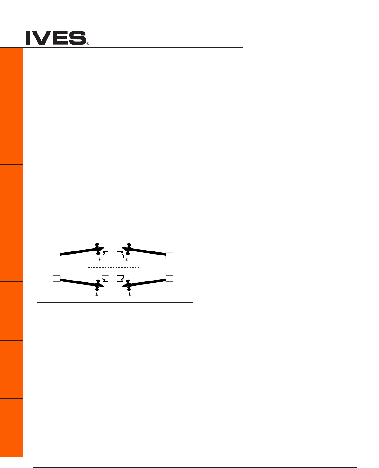
xi
Packaging, Handing
B
Pulls & Plates
A
Hinges & Pivots
C
Flush Bolts & Coordinators
D
Latches, Catches & Bolts
E
Stops
F
Exterior Hardware
G
Miscellaneous Hardware
Packaging Key
Many Ives items are available in a variety of packaging forms designated by a prefix. The Ives Price Book
contains the specific packaging options for each Ives product. Below is a description of these options.
Symbol Description of Package
C Carded
CGC Commercial Grade Carded
SC Schlage Branded Carded
SP Slim-Pak
SPS Schlage Branded Slim-Pak
Door Handing
LH INSIDE RH
Left Hand Right Hand
LRB RRB
Left Hand Right Hand
Reverse Bevel OUTSIDE Reverse Bevel
OUTSIDE
INSIDE
Ives Architectural hardware products

Ives Architectural hardware products A1
Architectural Hinges, Continuous Hinges and Pivots
B
Pulls & Plates
A1
Hinges & Pivots
C
Flush Bolts & Coordinators
D
Latches, Catches & Bolts
E
Stops
F
Exterior Hardware
G
Miscellaneous Hardware
Table Of Contents
Architectural Hinges page
General Hinge Information .............................................. A2
How to Order ...........................................................A3
ANSI Hinge Identification Reference .....................................A4
3PB1 3 Knuckle, Full Mortise ....................................A5
3CB1 3 Knuckle, Full Mortise ....................................A5
3CB1HW 3 Knuckle, Full Mortise ................................... A6
3SP1 3 Knuckle, Full Mortise ....................................A6
5PB1 5 Knuckle, Full Mortise ....................................A7
5BB1 5 Knuckle, Full Mortise ....................................A7
5BB1HW 5 Knuckle, Full Mortise ....................................A8
5BB1WT 5 Knuckle, Full Mortise ....................................A8
5BB4 5 Knuckle, Full Mortise ....................................A9
5BB4HW 5 Knuckle, Full Mortise ....................................A9
5BB1SC 5 Knuckle, Full Mortise ...................................A10
5BB1SCHW 5 Knuckle, Full Mortise ...................................A10
Electrified Hinge .........................................................A11
Residential Hinges ....................................................A12
Continuous Hinges ....................................................A13
Pivots ..........................................................A31
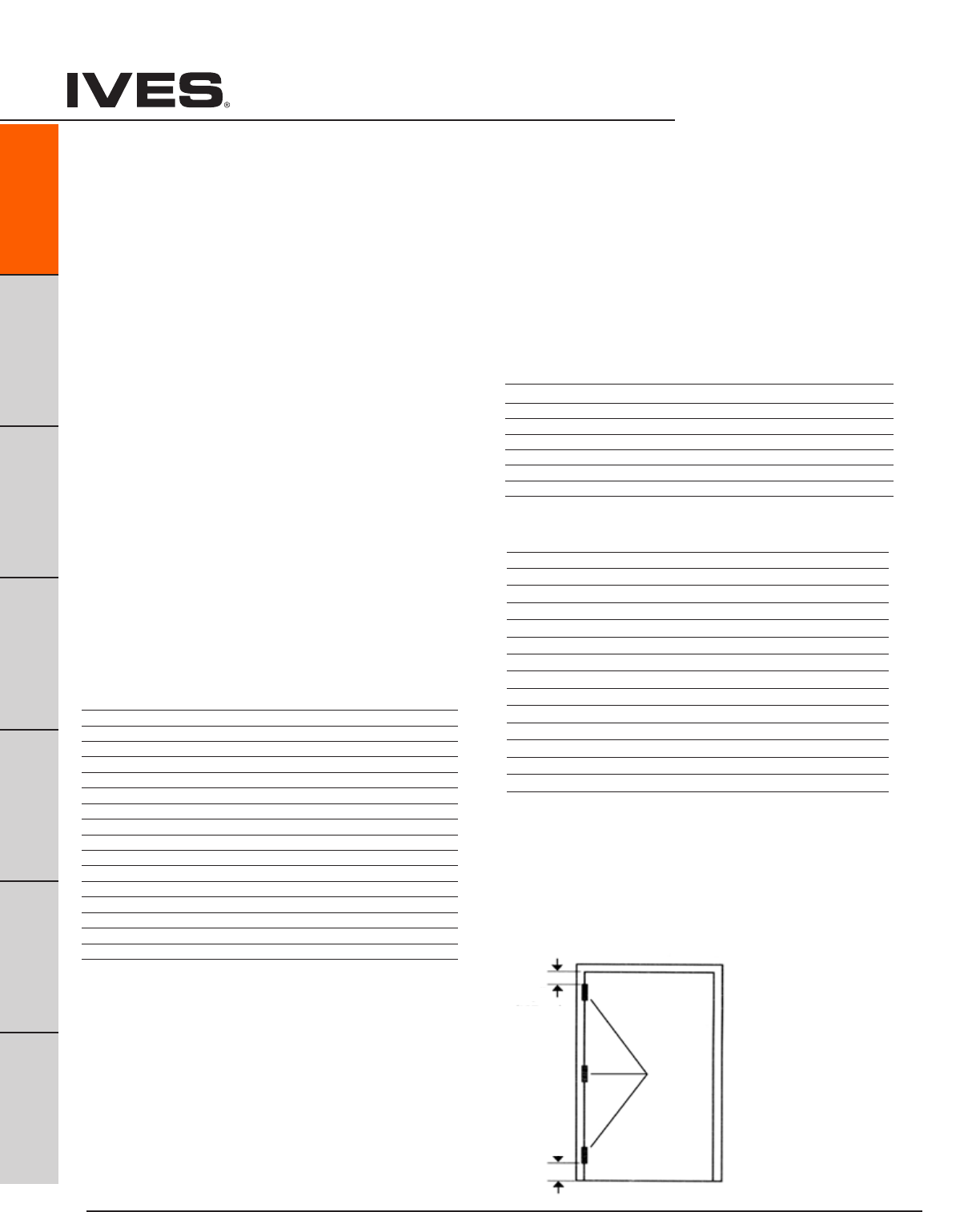
Ives Architectural hardware products
A2
Architectural Hinges, Continuous Hinges and Pivots
B
Pulls & Plates
A2
Hinges & Pivots
C
Flush Bolts & Coordinators
D
Latches, Catches & Bolts
E
Stops
F
Exterior Hardware
G
Miscellaneous Hardware
SELECTION OF THE PROPER WEIGHT AND BEARING TYPE
Standard Weight ..... Plain Bearing
Standard Weight ..... Ball Bearing, Concealed Bearing
Heavy Weight ......... Ball Bearing, Concealed Bearing
CONSIDERATIONS TO DETERMINE WEIGHT AND BEARING TYPE:
- Weight of Door
- Frequency of use
- Frame
- Door Hardware
Always use ball bearing or concealed bearing hinges for doors with door
closers and in all fire rated openings. Heavy weight doors and high fre-
quency doors should use heavy weight ball bearing or concealed bearing
hinges.
CONSIDERATIONS TO DETERMINE HINGE SIZE
- Door Width
- Door Thickness
- Weight
- Clearance
GUIDELINES FOR HINGE HEIGHT
DOOR THICKNESS DOOR WIDTH HINGE HEIGHT
IN INCHES IN INCHES IN INCHES
1-3/8” Up to 32” 3-1/2
1-3/8 32” to 37” 4”
1-3/4 Up to 36” 4-1/2”
1-3/4 36” to 48” 5”
1-3/4 Over 48” 6”
2” - 2-1/2” Up to 42” 5” heavy weight
2” - 2-1/2” Over 42” 6” heavy weight
General Hinge Information
GUIDELINES FOR HINGE METAL
- Interior door or non-corrosive area use: Plated or painted Steel
- Interior labeled door use: Plated or Painted Steel, Stainless Steel
- Interior door in corrosive area use: Stainless Steel , Brass, Bronze
- Exterior doors use: Stainless Steel, Brass, Bronze
Standard pin material are Brass Hinge – Steel Pin,
Stainless Steel Hinge – Stainless Steel Pin, Steel Hinge – Steel Pin
GUIDELINES FOR FREQUENCY OF DOOR USAGE:
Build Type Daily Usage Hinge Type
High Frequency/ Heavy Weight Door
Large Department Store Entrance 5,000 Heavy Weight
Hospital Corridor and Surgical Doors 5,000 Heavy Weight
Large Office Building Entrance 4,000 Heavy Weight
School Entrance 1,250 Heavy Weight
School Toilet Door 1,250 Heavy Weight
Office Stairwell 500 Heavy Weight
Office Building Toilet Door 400 Heavy Weight
Medium Frequency/ Medium Weight Door
School Corridor Door 100 Standard Weight
Hospital Consultation Rooms 100 Standard Weight
Office Building Corridor Door 80 Standard Weight
Store Toilet Door 60 Standard Weight
Storage Room 50 Standard Weight
Low Frequency /Light Door
Residential Entrance 30 Plain Bearing
Interior Residential 20 Plain Bearing
ANSI/BHMA GRADE/MINIMUM CYCLE REQUIREMENTS
Grade 1: 2,500,000 Heavy Weight Ball & Concealed Bearing
Grade 2: 1,500,000 Standard Weight Ball & Concealed Bearing
Grade 3: 350,000 Light Weight Plain Bearing
CLEARANCE REQUIREMENT*
DOOR THICKNESS CLEARANCE NEEDED HINGE OPEN WIDTH
1-3/8 3/4 4
1-3/4 1 4
1-3/4 1-1/2 4-1/2
1-3/4 2 5
1-3/4 3 6
2 1 4-1/2
2 1-1/2 5
2 2-1/2 6
2-1/4 1 5
2-1/4 2 6
2-1/2 3/4 5
2-1/2 1-3/4 6
3 3/4 8
3 2-3/4 8
*Distance needed between wall and door at 180º to allow for any projections
from wall; trim, decorative molding, etc.
GUIDELINES FOR NUMBER OF HINGES
- Doors under 7'6" ........ 3 hinges
- Doors over 7'6" .......... 4 hinges
LOCATION OF HINGES
Top hinge 5" from jamb
rabbet to top of barrel
Bottom hinge 10" from
bottom edge of barrel to
finished floor
Third hinge centered
between top and bottom
hinges
Note: Some western
states use a standard 7"
from top and 11" from the
bottom
Equal
5"
(127mm)
10"
(254mm)

Ives Architectural hardware products A3
Architectural Hinges, Continuous Hinges and Pivots
B
Pulls & Plates
A3
Hinges & Pivots
C
Flush Bolts & Coordinators
D
Latches, Catches & Bolts
E
Stops
F
Exterior Hardware
G
Miscellaneous Hardware
How to Order:
Number of Knuckles:
3 - 3 Knuckle
5 - 5 Knuckle
Function:
PB Plain Bearing
BB Ball Bearing
CB Concealed Bearing
SP Spring Hinge
Type:
1 Full Mortise
2 Half Mortise
3 Full Surface
4 Half Surface
Weight/Options:
Blank Standard Weight
HW Heavy Weight
SC Swing Clear
SH Security Stud
WT Wide Throw
HT Hospital Tip
RC Round Corners, 1/4" or 5/8" Radius
Size Examples:
3.5 x 3.5
4 x 4
4.5 x 4
4.5 x 4.5
Finish (Some models require extended lead times):
600 USP - Steel
605 US3 - Brass
606 US4 - Brass
612 US10 - Brass
613 US10B - Brass
619 US15 - Brass
625 US26 - Brass
626 US26D - Brass
630 US32D - Stainless
632 US3 - Steel
633 US4 - Steel
639 US10 - Steel
640 US10B - Steel
641 US10A - Steel
643 US11 - Steel
646 US15 - Steel
651 US26 - Steel
652 US26D - Steel
Special Pins Applications:
NRP Non-Removable Pin
TW4 Four Wire
TW8 Eight Wire
MON Monitor
TW4M Four Wire with Monitor
TW8M Eight Wire with Monitor
Ives Hinge Number System
Please note: For availability of specific models, please refer to the item’s catalog page or consult Customer Service.
5 - BB - 1 - HW - 4.5x4.5 - 652 - NRP
4.5 x 5
4.5 x 6
5 x 4.5
5 x 5
5 x 6
5 x 7
Larger sizes, up to 6 x 8 are available. Consult factory.

Ives Architectural hardware products
A4
Architectural Hinges
B
Pulls & Plates
A4
Hinges & Pivots
C
Flush Bolts & Coordinators
D
Latches, Catches & Bolts
E
Stops
F
Exterior Hardware
G
Miscellaneous Hardware
ANSI Hinge Identification Reference
A = ANSI
First number indicates material
1 – Cast, forged or extruded brass or bronze
2 – Wrought brass or bronze
5 – Stainless steel
8 – Wrought or forged steel, or malleable iron
Second number indicates product type
1 – Full mortise
2 – Half mortise
3 – Full surface
4 – Half surface
5 – Anchor, pivot reinforced or thrust pivot unit or hinge sets
6 – Olive knuckle hinges
7 – Pivot hinge
8 – Rescue hardware
Third number indicates function
1 – Anti-friction bearing
2 – Anti-friction bearing, swing clear
3 – Plain bearing
4 – 4 to 0, special conditions
Fourth number indicates grade
1 – Grade 1, 4BB Extra Heavy Duty
2 – Grade 2, 2BB Standard Duty
3 – Grade 3, Plain Bearing
Example:
A8111 – Steel, Full Mortise, Anti-friction, Grade 1
A5112 – Stainless, Full Mortise, Anti Friction Bearing, Grade 2

Ives Architectural hardware products
Architectural Hinges
B
Pulls & Plates
A5
Hinges & Pivots
C
Flush Bolts & Coordinators
D
Latches, Catches & Bolts
E
Stops
F
Exterior Hardware
G
Miscellaneous Hardware
A5
Meets ANSI/BHMA A156.1
A8133 – Steel
A5133 – Stainless Steel
A2133 – Brass
3PB1 3 Knuckle, Plain Bearing Full Mortise Hinge
• Forstandardweightdoors
• Lowfrequencyusage
• Packedwithwoodandmetalscrews
Not for use with a door closer.
Options
•NRP,Non-RemovablePin
•SH,SecurityStud
•HT,HospitalTip
•RC,RoundCorners-1/4"or5/8"Radius
•SEC,SecurityFasteners-Pin-in-Socket
Dimensions
Size (Inches) Size (mm) Gauge
3.5 x 3.5 90 x 90 0.134
4 x 4 102 x 102 0.134
4.5 x 4 114 x 102 0.134
4.5 x 4.5 114 x 114 0.134
5 x 4.5 127 x 114 0.134
Meets ANSI/BHMA A156.1
A8112 – Steel
A5112 – Stainless Steel
A2112 – Brass
3CB1 3 Knuckle, Concealed Bearing Full Mortise Hinge
• Forstandardweightdoors
• Mediumfrequencyusage
• Packedwithwoodandmetalscrews
Options
•NRP,Non-RemovablePin
•SH,Securitystud
•HT,HospitalTip
•RC,RoundCorners-1/4"or5/8"Radius
•SEC,SecurityFastners-Pin-in-Socket
Dimensions
Size (Inches) Size (mm) Gauge
3.5 x 3.5 90 x 90 0.134
4 x 4 102 x 102 0.134
4.5 x 4 114 x 102 0.134
4.5 x 4.5 114 x 114 0.134
5 x 4.5 127 x 114 0.134
Finishes brass
Ives Finish US3 US4 US10 US10B US10A US11 US15 US26 US26D
BHMA 605 606 612 613 614 616 619 625 626
Finishes steel
Ives Finish USP US3 US4 US10 US10B US10A US11 US15 US26 US26D
BHMA 600 632 633 639 640 641 643 646 651 652
Finishes stainless steel
Ives Finish US32 US32D
BHMA 629 630
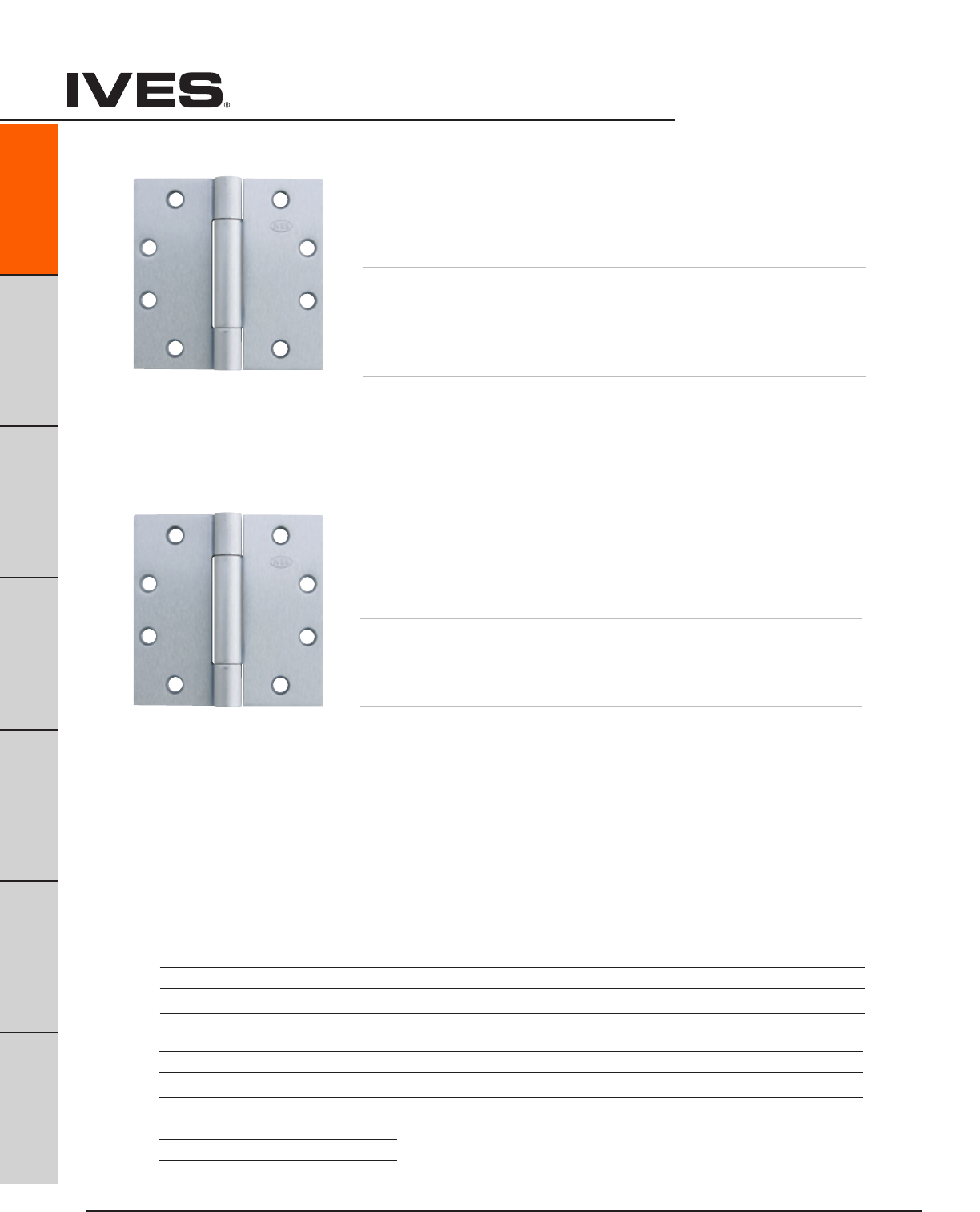
Ives Architectural hardware products
A6
Architectural Hinges
B
Pulls & Plates
A6
Hinges & Pivots
C
Flush Bolts & Coordinators
D
Latches, Catches & Bolts
E
Stops
F
Exterior Hardware
G
Miscellaneous Hardware
Meets ANSI/BHMA A156.7
K81071F – Steel
K51071F – Stainless Steel
UL listed for use with fire rated doors
3SP1 3 Knuckle Spring Full Mortise Hinge
• Forautomaticclosingofdoors
• Packedwithwoodandmetalscrews
Options
•HT,HospitalTip
•RC,RoundCorners-1/4"or5/8"Radius
•SEC,SecurityFastners-Pin-in-Socket
Dimensions
Size (Inches) Size (mm) Gauge
4 x 4 102 x 102 0.134
4.5 x 4 114 x 102 0.134
4.5 x 4.5 114 x 114 0.134
Meets ANSI/BHMA A156.1
A8112 – Steel
A5112 – Stainless Steel
A2112 – Brass
3CB1HW 3 Knuckle, Concealed Bearing Full Mortise Hinge
• Forheavyweightdoors
• Highfrequencyusage
• Packedwithwoodandmetalscrews
Options
•NRP,Non-RemovablePin
•SH,Securitystud
•HT,HospitalTip
•RC,RoundCorners-1/4"or5/8"Radius
•SEC,SecurityFastners-Pin-in-Socket
Dimensions
Size (Inches) Size (mm) Gauge
4.5 x 4 114 x 102 0.180
4.5 x 4.5 114 x 114 0.180
5 x 4.5 127 x 114 0.190
5 x 5 127 x 127 0.190
Finishes brass
Ives Finish US3 US4 US10 US10B US10A US11 US15 US26 US26D
BHMA 605 606 612 613 614 616 619 625 626
Finishes steel
Ives Finish USP US3 US4 US10 US10B US10A US11 US15 US26 US26D
BHMA 600 632 633 639 640 641 643 646 651 652
Finishes stainless steel
Ives Finish US32 US32D
BHMA 629 630

Ives Architectural hardware products
Architectural Hinges
B
Pulls & Plates
A7
Hinges & Pivots
C
Flush Bolts & Coordinators
D
Latches, Catches & Bolts
E
Stops
F
Exterior Hardware
G
Miscellaneous Hardware
A7
Meets ANSI/BHMA A156.1
A8112 – Steel
A5112 – Stainless Steel
A2112 – Brass
5BB1 5 Knuckle, Ball Bearing Full Mortise Hinge
• Forstandardweightdoors
• Mediumfrequencyusage
• 2ballbearing
• Packedwithwoodandmetalscrews
Options
•NRP,Non-RemovablePin
•SH,SecurityStud
•HT,HospitalTip
•RC,RoundCorners-1/4"or5/8"Radius
•SEC,SecurityFastners-Pin-in-Socket
Dimensions
Size (Inches) Size (mm) Gauge
3.5 x 3.5 80 x 102 0.130
4 x 4 102 x 102 0.130
4.5 x 4 114 x 102 0.134
4.5 x 4.5 114 x 114 0.134
Size (Inches) Size (mm) Gauge
5 x 4.5 127 x 114 0.146
5 x 5 127 x 127 0.146
Meets ANSI/BHMA A156.1
A8133 – Steel
A5133 – Stainless Steel
A2133 – Brass
5PB1 5 Knuckle, Plain Bearing Full Mortise Hinge
• Forstandardweightdoors
• Lowfrequencyusage
• Packedwithwoodandmetalscrews
Not for use with a door closer.
Options
•NRP,Non-RemovablePin
•SH,SecurityStud
•HT,HospitalTip
•RC,RoundCorners-1/4"or5/8"Radius
•SEC,SecurityFastners-Pin-in-Socket
Dimensions
Size (Inches) Size (mm) Gauge
3.5 x 3.5 89 x 89 0.123
4 x 4 102 x 102 0.134
4.5 x 4 114 x 102 0.134
4.5 x 4.5 114 x 114 0.134
5 x 4.5 127 x 114 0.134
Finishes brass
Ives Finish US3 US4 US10 US10B US10A US11 US15 US26 US26D
BHMA 605 606 612 613 614 616 619 625 626
Finishes steel
Ives Finish USP US3 US4 US10 US10B US10A US11 US15 US26 US26D
BHMA 600 632 633 639 640 641 643 646 651 652
Finishes stainless steel
Ives Finish US32 US32D
BHMA 629 630
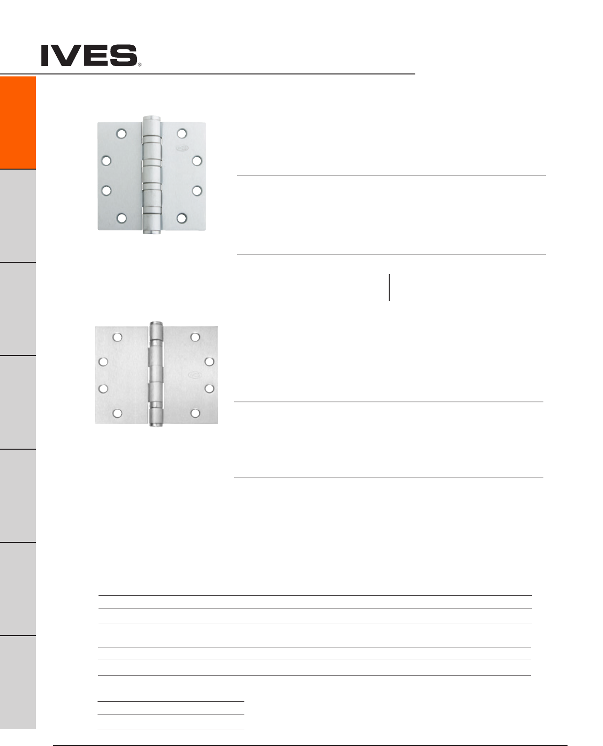
Ives Architectural hardware products
A8
Architectural Hinges
B
Pulls & Plates
A8
Hinges & Pivots
C
Flush Bolts & Coordinators
D
Latches, Catches & Bolts
E
Stops
F
Exterior Hardware
G
Miscellaneous Hardware
Meets ANSI/BHMA A156.1
A8111 – Steel
5BB1WT 5 Knuckle, Ball Bearing, Wide Throw
Full Mortise Hinge
• Formediumweightdoors
• Mediumfrequencyusage
• 2ballbearing
• Packedwithwoodandmetalscrews
Options
•NRP,Non-RemovablePin
•SH,SecurityStud
•HT,HospitalTip
•RC,RoundCorners-1/4"or5/8"Radius
•SEC,SecurityFastners-Pin-in-Socket
Dimensions
Size (Inches) Size (mm) Gauge
4.5 x 5 114 x 127 0.134
4.5 x 6 114 x 152 0.134
5 x 6 127 x 152 0.146
5 x 7 127 x 178 0.146
5 x 8 127 x 203 0.146
Meets ANSI/BHMA A156.1
A8111 – Steel
A5111 – Stainless Steel
A2111 – Brass
5BB1HW 5 Knuckle, Ball Bearing, Heavy Weight
Full Mortise Hinge
• Forheavyweightdoors
• Highfrequencyusage
• 4ballbearing
• Packedwithwoodandmetalscrews
Options
•NRP,Non-RemovablePin
•SH,SecurityStud
•HT,HospitalTip
•RC,RoundCorners-1/4"or5/8"Radius
•SEC,SecurityFastners-Pin-in-Socket
Dimensions
Size (Inches) Size (mm) Gauge
4.5 x 4 114 x 102 0.180
4.5 x 4.5 114 x 114 0.180
Size (Inches) Size (mm) Gauge
5 x 4.5 127 x 114 0.190
5 x 5 127 x 127 0.190
Finishes brass
Ives Finish US3 US4 US10 US10B US10A US11 US15 US26 US26D
BHMA 605 606 612 613 614 616 619 625 626
Finishes steel
Ives Finish USP US3 US4 US10 US10B US10A US11 US15 US26 US26D
BHMA 600 632 633 639 640 641 643 646 651 652
Finishes stainless steel
Ives Finish US32 US32D
BHMA 629 630
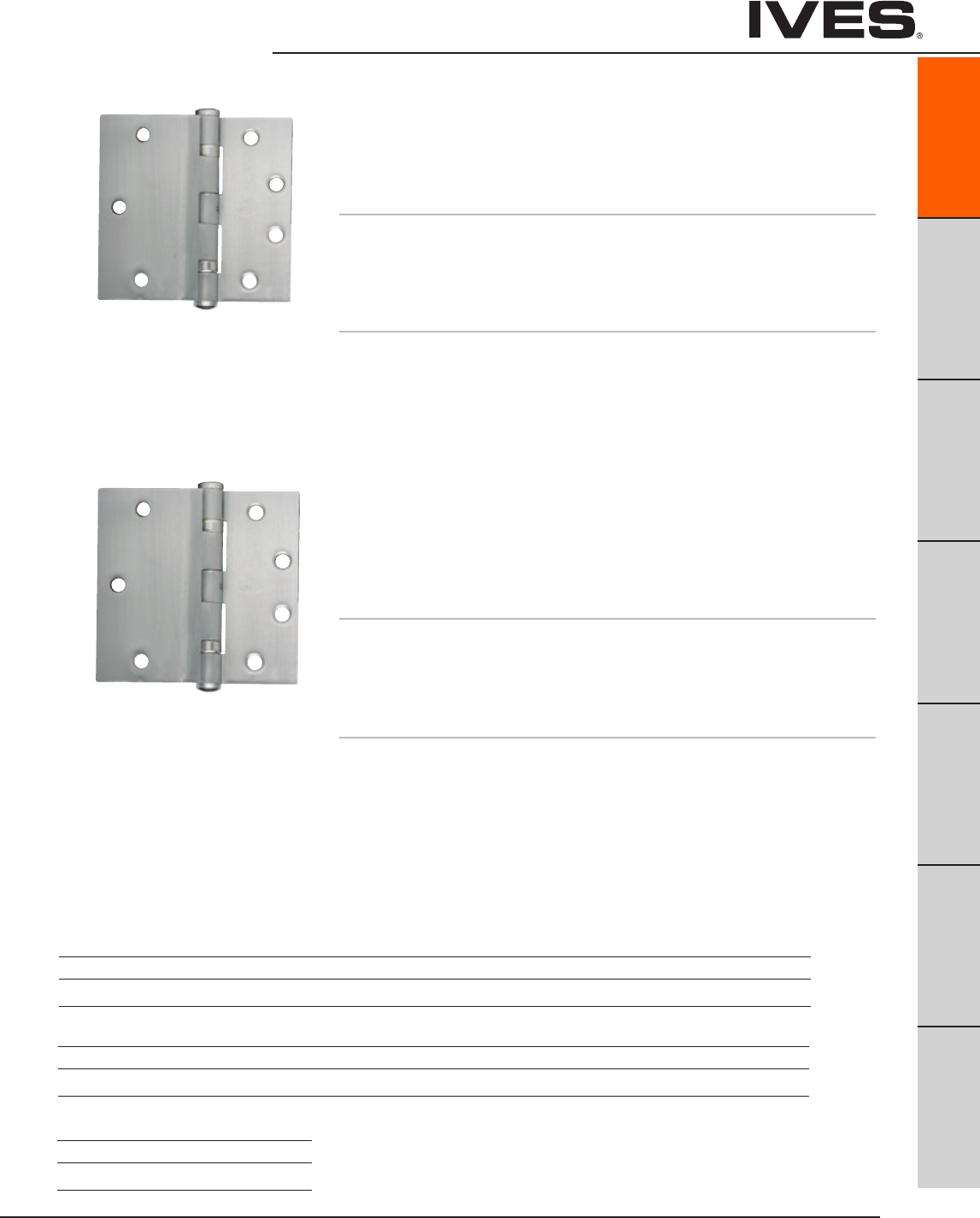
Ives Architectural hardware products
Architectural Hinges
B
Pulls & Plates
A9
Hinges & Pivots
C
Flush Bolts & Coordinators
D
Latches, Catches & Bolts
E
Stops
F
Exterior Hardware
G
Miscellaneous Hardware
A9
Meets ANSI/BHMA A156.1
A8412 – Steel
5BB4 5 Knuckle, Ball Bearing, Half Surface Hinge
• Forstandardweightdoors
• Mediumfrequencyusage
• 2ballbearing
• Packedwiththroughbolts,grommetsandsheetmetalscrews
Options
•NRP,Non-RemovablePin
•HT,HospitalTip
•RC,RoundCorners-1/4"or5/8"Radius
•SEC,SecurityFastners-Pin-in-Socket
Dimensions
Size (Inches) Size (mm) Gauge
4.5 114 0.134
Meets ANSI/BHMA A156.1
A8411 – Steel
5BB4HW 5 Knuckle, Ball Bearing, Half Surface
Heavy Weight Hinge
• Forheavyweightdoors
• Highfrequencyusage
• 4ballbearing
• Packedwiththroughbolts,grommetsandsheetmetalscrews
Options
•NRP,Non-RemovablePin
•HT,HospitalTip
•RC,RoundCorners-1/4"or5/8"Radius
•SEC,SecurityFastners-Pin-in-Socket
Dimensions
Size (Inches) Size (mm) Gauge
4.5 114 0.180
Finishes brass
Ives Finish US3 US4 US10 US10B US10A US11 US15 US26 US26D
BHMA 605 606 612 613 614 616 619 625 626
Finishes steel
Ives Finish USP US3 US4 US10 US10B US10A US11 US15 US26 US26D
BHMA 600 632 633 639 640 641 643 646 651 652
Finishes stainless steel
Ives Finish US32 US32D
BHMA 629 630

Ives Architectural hardware products
A10
Architectural Hinges
B
Pulls & Plates
A10
Hinges & Pivots
C
Flush Bolts & Coordinators
D
Latches, Catches & Bolts
E
Stops
F
Exterior Hardware
G
Miscellaneous Hardware
Meets ANSI/BHMA A156.1
A8121 – Steel
5BB1SCHW 5 Knuckle, Ball Bearing, Swing Clear
Heavy Weight Full Mortise Hinge
• Forheavyweightdoors
• Highfrequencyusage
• 2ballbearing
• Packedwithflatheadwoodandmetalscrews
Designed to completely clear the opening when door is opened 92 degrees.
Options
•NRP,Non-RemovablePin
•B,bevelededgedoor
•HT,HospitalTip
•RC,RoundCorners-1/4"or5/8"Radius
•SEC,SecurityFastners-Pin-in-Socket
Dimensions
Size (Inches) Size (mm) Gauge
4.5 114 0.180
5 127 0.190
Meets ANSI/BHMA A156.1
A8122 – Steel
A5122 – Stainless Steel
A2122 – Brass
5BB1SC 5 Knuckle, Ball Bearing, Swing Clear
Full Mortise Hinge
• Forstandardweightdoors
• Squareedgestandard
• Mediumfrequencyusage
• 2ballbearing
• Packedwithflatheadwoodandmetalscrews
Designed to completely clear the opening when door is opened 92 degrees.
Options
•NRP,Non-RemovablePin
•B,bevelededgedoor
•HT,HospitalTip
•RC,RoundCorners-1/4"or5/8"Radius
•SEC,SecurityFastners-Pin-in-Socket
Dimensions
Size (Inches) Size (mm) Gauge
4.5 114 0.134
5 127 0.145
Finishes brass
Ives Finish US3 US4 US10 US10B US10A US11 US15 US26 US26D
BHMA 605 606 612 613 614 616 619 625 626
Finishes steel
Ives Finish USP US3 US4 US10 US10B US10A US11 US15 US26 US26D
BHMA 600 632 633 639 640 641 643 646 651 652
Finishes stainless steel
Ives Finish US32 US32D
BHMA 629 630
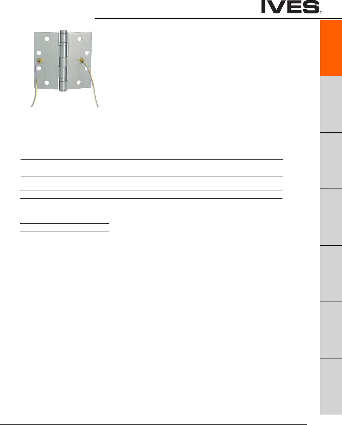
Ives Architectural hardware products
Architectural Hinges
B
Pulls & Plates
A11
Hinges & Pivots
C
Flush Bolts & Coordinators
D
Latches, Catches & Bolts
E
Stops
F
Exterior Hardware
G
Miscellaneous Hardware
A11
UL Listed - UL634
Meets ANSI/BHMA A156.1
A8111 – Steel
A5111 – Stainless Steel
A2111 – Brass
Electrified Hinge
Available Options
- Through Wire - TW4 (4 wires) & TW8 (8 wires)
- Monitor – MON
- Through Wire with Monitor – TW4M & TW8M
• Available in 3 and 5 Knuckle
• Onehingeperbox,packedwithwoodandmachinescrews
• HingeisNRPasastandard
• Highqualitybrassferrulesandplastictubingprotectthewires
• Through-wirehingescycletestedtoensuredurability
• Iveswarrantyapplies-12monthsfromdateofshipment
Through-Wire is rated for 50 volts AC/DC at 3.5 amp continuous and 16 amp pulse,
maximum pulse 400 mili second.
Monitor rated 30VDC at .5 amp
Special wire configurations available, contact factory.
Finishes brass
Ives Finish US3 US4 US10 US10B US10A US11 US15 US26 US26D
BHMA 605 606 612 613 614 616 619 625 626
Finishes steel
Ives Finish USP US3 US4 US10 US10B US10A US11 US15 US26 US26D
BHMA 600 632 633 639 640 641 643 646 651 652
Finishes stainless steel
Ives Finish US32 US32D
BHMA 629 630

Ives Architectural hardware products
A12
Architectural Hinges
B
Pulls & Plates
A12
Hinges & Pivots
C
Flush Bolts & Coordinators
D
Latches, Catches & Bolts
E
Stops
F
Exterior Hardware
G
Miscellaneous Hardware
1000 Series Residential Hinges
• Fullmortisehingesin2sizes:3-1/2"and4".
• Twocorneroptions:Squarecornersand5/8"or1/4"
radius corners.
• Substratesinclude:Steel.
Model Size Corner
1010 3-1/2" x 3-1/2" Square Corner
1011 3-1/2" x 3-1/2" 5/8" Radius Corner
1012 3-1/2" x 3-1/2" 1/4" Radius Corner
1020 4" x 4" Square Corner
1021 4" x 4" 5/8" Radius Corner
1010
Schlage Carded Only
1011
1012
Schlage Carded Only
1021
Schlage Carded Only
1020
Schlage Carded Only
Finishes steel
Ives Finish F605E F609E F619E F620E* F625E** F716E
BHMA 632 646 651
* not available on 1012 hinge
* only available on 1011
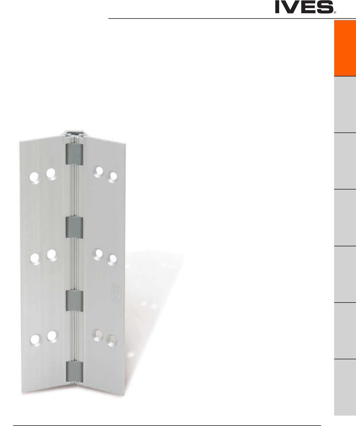
Ives Architectural hardware products
Continuous Hinges
Ives Continuous Hinges are designed to last the life of the building.
The unique design distributes the weight of the door along the entire
length of the frame, reducing the high amount of stress normally
associated at top of door and frame on butt hinge applications. Not
only does this reduce hinge failure, it also keeps your door in constant
alignment, eliminating the chance of door sag. These characteristics
make continuous hinges suitable for high use/high traffic doors.
The design of a continuous hinge eliminates the gap between the
door and the frame. The absence of gap also helps prevents finger
from being pinched, making it a safer device than traditional hinges.
These benefits result in higher efficiency and less maintenance,
maximizing the value of your opening investment.
Continuous hinges are available in two styles; aluminum geared
and pin and barrel in steel or stainless steel.
B
Pulls & Plates
A13
Hinges & Pivots
C
Flush Bolts & Coordinators
D
Latches, Catches & Bolts
E
Stops
F
Exterior Hardware
G
Miscellaneous Hardware
A13
Continuous Hinge Table Of Contents page
Continuous Hinge Types ...............................................A14
Cross Reference Guide .................................................A15
Aluminum Geared Hinges
General Information ...................................................A16
Electrified Options .....................................................A16
How to Order ..........................................................A17
Door Sizing ............................................................A18
045HD ...................Half Surface ................................A19
046HD ...................Half Surface ................................A19
053HD ...................Half Surface ...............................A20
054HD ...................Half Surface ...............................A20
112HD .....................Full Mortise .................................A21
157XY ....................Full Surface, Center Pivot ...................A21
210HD ....................Full Surface, Swing Clear .................. A22
224HD ....................Full Mortise, Edge Protector ............... A23
Electrical Cutouts ..................................................... A23
Pin and Barrel Hinges
General Information ..................................................A24
Electrified Options ....................................................A24
How to Order .........................................................A25
Door Sizing ...........................................................A26
600, 700 .................Full Mortise ................................ A27
602, 702 .................Full Surface. . . . . . . . . . . . . . . . . . . . . . . . . . . . . . . . A27
611, 711 ....................Swing Clear ................................ A28
705 .......................Full Mortise, Full Wrap ..................... A28
715 .......................Full Mortise, Full Wrap ..................... A29
Electrical Cutouts .....................................................A30

Ives Architectural hardware products
A14
Continuous Hinges
B
Pulls & Plates
A14
Hinges & Pivots
C
Flush Bolts & Coordinators
D
Latches, Catches & Bolts
E
Stops
F
Exterior Hardware
G
Miscellaneous Hardware
Aluminum Geared
Geared continuous hinges utilize a single gear section for the leaf and
a separate gear section for the frame side of the door. The two are
held in place together by a full length cover channel and rotate on a
series of bearings.
Pin and Barrel
Pin and Barrel hinges share many of the same characteristics of a
traditional hinge. Both have a center pin and rolled knuckles.
However, a continuous Pin and Barrel hinge stretches along the
entire length of the frame. IVES offers both stainless steel and
primed steel to best match your specific application.
” 4 / 3 - 1
” 2 / 1
s s e n k c i h T e g n i H ” 5 7 0 . 0 A G
”4/ 1
” 6 1 / 1
”4/ 1- 2
” 8 / 1
” 8 / 3
007 ,006 ,005 sevI
7/32" [5.6] HINGE ALLOWANCE
2" [50.8]
GA 0.075" HINGE THICKNESS
GA. 0.060"
[1.5]
DOOR
] 3 . 1 [ " 0 5 0 . 0 . A G
] 6 . 1 [ " 6 1 / 1
] 5 . 4 4 [ " 6 1 / 1 1
" 4 / 3
] 1 . 9 1 [
FRAME
" 2 / 1
] 7 . 2 1 [
" 8 / 1
] 5 . 9 [
] 7 . 2 1 [ " 2 / 1
] 5 . 5 5 [ " 6 1 / 3 2
" 8 / 5
] 9 . 5 1 [
" 4 / 3
] 1 . 9 1 [
" 8 / 3
] 5 . 9 [
HINGE
” 4 / 3 - 1
” 8 / 3
” 2 3 / 5
” 4 / 3
e g n i H ” 5 7 0 . 0 A G
s s e n k c i h T
” 4 / 1
” 8 / 3 - 1
”
16
/9-1
117 ,116 sevI
5/32" [4.0] HINGE ALLOWANCE
] 3 . 1 [ " 0 5 0 . 0 . A G " 4 / 3
] 1 . 9 1 [
] 5 . 4 4 [ " 4 / 3 1
HINGE
" 2 / 1
] 7 . 2 1 [
0.750"
[19.0]
5/16"
[7.9]
GA. 0.075" HINGE THICKNESS
1/2"
[12.7]
9/16"
[14.3]
1 3/8" [34.9]
2" [50.8]
" 4 / 1
] 4 . 6 [
FRAME DOOR
GA. 0.060"
[1.5]
Lifetime Warranty Ives continuous hinges carry a limited lifetime war-
ranty, ensuring your opening will function to your satisfaction every time.

Ives Architectural hardware products
Continuous Hinges
B
Pulls & Plates
A15
Hinges & Pivots
C
Flush Bolts & Coordinators
D
Latches, Catches & Bolts
E
Stops
F
Exterior Hardware
G
Miscellaneous Hardware
A15
Ives Hager Markar McKinney Pemko Select Stanley
Geared
045HD 780-045HD
046HD 780-046HD
053HD 780-053HD
054HD 780-054HD
112HD 780-112HD MCK-12HD FMSLFHD SL11HD 661HD
210HD 780-210HD MCK-22HD FSHD SL21HD 665HD
224HD 780-224HD MCK-25HD FMHD SL24HD 662HD
157XY* 780-157HD MCK-58HD FSCPHD SL57HD 664HD
157HD 780-157HD MCK-58HD FSCPHD SL57HD 664HD
Pin and Barrel
600 FM200 SL200
602 FS202
611 N/A
700 790-900 FM300 SL300 651
702 FS302 SL302
705 790-905 HG305 SL305 652
711 790-911 HG311 SL311 656
715 790-915 HG315 653
Cross Reference Guide
*Application only. Features and benefits exceed current market standard.

Ives Architectural hardware products
A16
Continuous Hinges
B
Pulls & Plates
A16
Hinges & Pivots
C
Flush Bolts & Coordinators
D
Latches, Catches & Bolts
E
Stops
F
Exterior Hardware
G
Miscellaneous Hardware
General Information
Material
6063-T6 Aluminum
Standard Lengths
83", 85", 95", 120"
Custom lengths are available up to 120", consult factory.
Finishes
CL - US28 (628) Clear Anodized
BR - 313AN (710) Dark Bronze
Hinge Duty
All Ives Aluminum Geared Hinges are Heavy Duty (HD).
Amount of bearings varies by size:
83" – 32 Bearings
85" – 32 Bearings
95" – 36 Bearings
120"- 47 Bearings
Door Weight
Each hinge can hold a door up to 450 lbs (Rivet nuts recommended)
and a max door width of 4'0".
ANSI Certified
All Ives Aluminum Geared Hinges excluding the 157XY are certified to ANSI 156.26, Grade 1
UL Listed
All Ives Aluminum Geared Hinges excluding the 157XY are tested and approved UL 10C (90 minutes).
Field Modifications:
All Ives Aluminum Geared Continuous Hinges can be cut to length during installation. The unique
mounting pattern allows to cut up to 6" from bottom while still having double row fasteners. If cut
more than 13.5", other modifications may be necessary.
Electrification Options
Only available for the full mortise hinges
Electric Power Transfer (EPT)
Electric power transfer provides a means of transferring power from the door frame to the edge of a
swinging door. Ives Continuous Hinges provide standard cut outs to fit Von Duprin EPT-2, EPT-10 and
PNT-1 devices. Consult factory for other electrical cut out options.
Electrical Through-Wire (TW)
Provides electric power transfer from the frame to the door in order to supply power to an electrified
mortise or cylindrical locks, exit devices with electric latch retraction, and/or electric strikes (pairs of
doors). Through-wire is rated 50 volts AC/DC at 3.5 amp continuous and 16 amp pulse. Maximum pulse
400 milliseconds. Ives thru-wire hinges are fully compatible with 4 wire and 8 wire installations.
Aluminum Geared Hinges

Ives Architectural hardware products
Continuous Hinges
B
Pulls & Plates
A17
Hinges & Pivots
C
Flush Bolts & Coordinators
D
Latches, Catches & Bolts
E
Stops
F
Exterior Hardware
G
Miscellaneous Hardware
A17
How to Order:
Model
045HD Half Surface
046HD Half Surface
053HD Half Surface
054HD Half Surface
112HD Full Mortise
157XY Full Surface - Center Pivot
157HD Full Surface - Center Pivot
210HD Full Surface - Swing Clear
224HD Full Mortise - Edge Protector
Finish
CL Clear
BR Bronze
Custom finishes available, consult factory
Length
83"
* 85"
95"
120"
Options
**EPT Electric Power Transfer Prep
**TW8 Electric Through Wire
*SEC Security Fasteners - Pin-in-Socket
WD Wood Fasteners
TF Thread forming screws (pilot hole required)
HT Hospital Tip
TWP Through Wire Panel
* Not available with 157XY Continuous Hinge
** Full Mortise Models Only
112HD - CL - 83 - EPT
Aluminum Geared Hinges
Other lengths available up to 120", consult factory. Handing required.
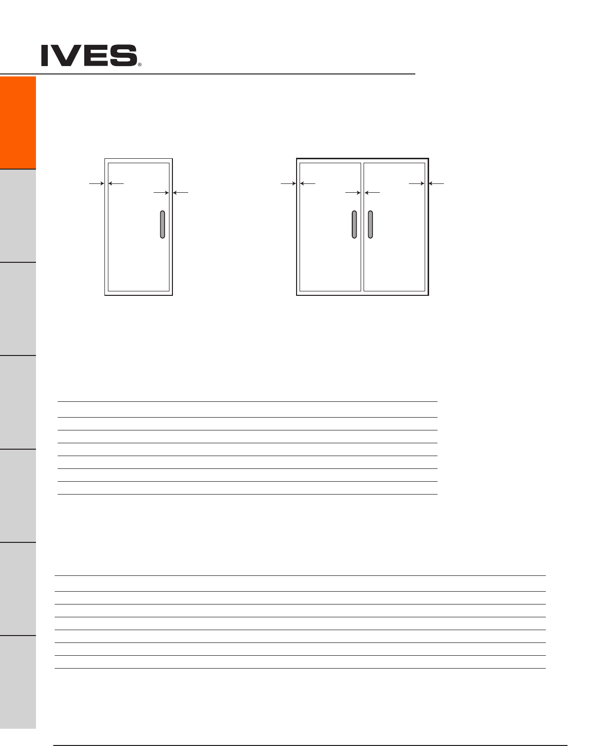
Ives Architectural hardware products
A18
Continuous Hinges
B
Pulls & Plates
A18
Hinges & Pivots
C
Flush Bolts & Coordinators
D
Latches, Catches & Bolts
E
Stops
F
Exterior Hardware
G
Miscellaneous Hardware
SINGLE DOOR
Door Under-Sizing
Hinge-Side Lock-Side Frame Beveled Door Square Beveled
Model Clearance Clearance Irregularity Clearance Edged Edged
045HD 5/32" 1/8" 1/32" 1/32" 5/16" 11/32"
046HD 5/32" 1/8" 1/32" 1/32" 5/16" 11/32"
053HD 5/32" 1/8" 1/32" 1/32" 5/16" 11/32"
054HD 5/32" 1/8" 1/32" 1/32" 5/16" 11/32"
112HD 5/16" 1/8" 1/32" 1/32" 15/32" 1/2"
224HD 5/16" 1/8" 1/32" 1/32" 15/32" 1/2"
210HD 1/16" 1/8" 1/32" 1/32" 7/32" 1/4"
157XY 1/16" 1/8" 1/32" 1/32" 7/32" 1/4"
PAIR OF DOORS
Door Under-Sizing
Square Square Beveled Beveled
Hinge-Side Lock-Side Frame Beveled Door Edged Edged Edged Edged
Model Clearance Clearance Irregularity Clearance Total Each Door Total Each Door
045HD 5/32" 3/16" 1/16" 1/16" 9/16" 9/32" 5/8" 5/16"
046HD 5/32" 3/16" 1/16" 1/16" 9/16" 9/32" 5/8" 5/16"
053HD 5/32" 3/16" 1/16" 1/16" 9/16" 9/32" 5/8" 5/16"
054HD 5/32" 3/16" 1/16" 1/16" 9/16" 9/32" 5/8" 5/16"
112HD 5/16" 3/16" 1/16" 1/16" 7/8" 7/16" 15/16" 15/32"
224HD 5/16" 3/16" 1/16" 1/16" 7/8" 7/16" 15/16" 15/32"
210HD 1/16" 3/16" 1/16" 1/16" 3/8" 3/16" 7/16" 7/32"
157XY 1/16" 3/16" 1/16" 1/16" 3/8" 3/16" 7/16" 7/32"
Hinge
Side
Clearance
1/32”
Frame
Irre
g
ularity
1/8” Hinge
Side
Clearance
Hinge
Side
Clearance
1/16”
Frame
Irre
g
ularity
3/16”
Aluminum Geared Hinges - Clearance Requirements
Templates and installation instructions available on line at www.allegion.com/us

Ives Architectural hardware products
045HD Half Surface Continuous Hinge
• Half surface for retrofit or new construction
• Handing required when modified
• Frame leaf depth 1-9/16"
• 9/32" door inset
Standard lengths 83", 85", 95", 120"
Standard Mounting Hardware
12-24 x 1/2" steel self tapping screw
1/4-20 x 1-1/2" AL Sex Bolt
1/4-20 x 1" Steel Shoulder Bolt
12-24 x 3/4" Steel Self Drilling Shoulder Bolt
Optional SEC-Security Fasteners available
046HD Half Surface Continuous Hinge
• Half surface for retrofit or new construction
• Handing required when modified
• Frame leaf depth 1-15/16"
• 9/32" door inset
Standard lengths 83", 85", 95", 120"
Standard Mounting Hardware
12-24 x 1/2" steel self tapping screw
1/4-20 x 1-1/2" AL Sex Bolt
1/4-20 x 1" Steel Shoulder Bolt
12-24 x 3/4" Steel Self Drilling Shoulder Bolt
Optional SEC-Security Fasteners available
Finishes
Clear (CL), Dark Bronze (DB)
Custom Anodizing and Painting are
available, consult factory.
Finishes
Clear (CL), Dark Bronze (DB)
Custom Anodizing and Painting are
available, consult factory.
Continuous Hinges
B
Pulls & Plates
A19
Hinges & Pivots
C
Flush Bolts & Coordinators
D
Latches, Catches & Bolts
E
Stops
F
Exterior Hardware
G
Miscellaneous Hardware
A19
3-1/16"
1-9/32"
2-9/32"
1-9/16"
5/32" Clearance for Square Edge Door
3/16" Clearance For Beveled Edge Door
3-1/16"
1-9/32"
2-5/8"
1-15/16"
5/32" Clearance for Square Edge Door
3/16" Clearance For Beveled Edge Door
Aluminum Geared Hinges - Clearance Requirements

Ives Architectural hardware products
A20
Continuous Hinges
B
Pulls & Plates
A20
Hinges & Pivots
C
Flush Bolts & Coordinators
D
Latches, Catches & Bolts
E
Stops
F
Exterior Hardware
G
Miscellaneous Hardware
053HD Half Surface Continuous Hinge
• Half surface for retrofit or new construction
• Handing required when modified
• Frame leaf depth 1-9/16"
• 1/8" door inset
Standard lengths 83", 85", 95", 120"
Standard Mounting Hardware
12-24 x 1/2" steel self tapping screw
1/4-20 x 1-1/2" AL Sex Bolt
1/4-20 x 1" Steel Shoulder Bolt
12-24 x 3/4" Steel Self Drilling Shoulder Bolt
Optional SEC-Security Fasteners available
054HD Half Surface Continuous Hinge
• Half surface for retrofit or new construction
• Handing required when modified
• Frame leaf depth 1-15/16"
• 1/8" door inset
Standard lengths 83", 85", 95", 120"
Standard Mounting Hardware
12-24 x 1/2" steel self tapping screw
1/4-20 x 1-1/2" AL Sex Bolt
1/4-20 x 1" Steel Shoulder Bolt
12-24 x 3/4" Steel Self Drilling Shoulder Bolt
Optional SEC-Security Fasteners available
Finishes
Clear (CL), Dark Bronze (DB)
Custom Anodizing and Painting are
available, consult factory.
Finishes
Clear (CL), Dark Bronze (DB)
Custom Anodizing and Painting are
available, consult factory.
2-1/8"
1-5/32"
2-9/32"
1-9/16"
5/32" Clearance for Square Edge Door
3/16" Clearance For Beveled Edge Door
2-1/8"
1-5/32"
2-5/8"
1-15/16"
5/32" Clearance for Square Edge Door
3/16" Clearance For Beveled Edge Door
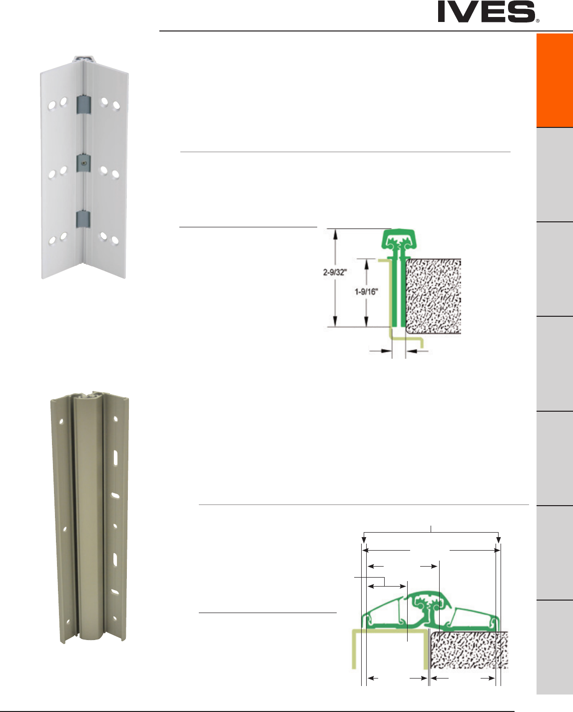
Ives Architectural hardware products
Continuous Hinges
B
Pulls & Plates
A21
Hinges & Pivots
C
Flush Bolts & Coordinators
D
Latches, Catches & Bolts
E
Stops
F
Exterior Hardware
G
Miscellaneous Hardware
A21
157XY Full Surface, Center Pivot
Aluminum Geared Continuous Hinge
• NonHanded
• NarrowFrame
• 1/16"DoorInset
• 48"MaximumDoorWidth
• Beveled or Square Edge Doors
• Apatentedeasy-to-install,heavyduty,fullsurfacecontinuoushinge
• Lateralandverticaladjustabilitywhilethedoorisstillhanging
For Doors Weighing up to 550 pounds
Standard lengths 83", 95", 119"
Standard Mounting Hardware
12-24 X 1/2" Steel Self Drilling
and Tapping Screws,
Optional Wood Screws and
Security Fasteners Available
Custom Paint Finish Available
Finishes
Clear (CL), Dark Bronze (DB)
112HD Full Mortise Aluminum Geared Continuous Hinge
• Non Handed
• Flush Mounted, No Inset
• 48"MaximumDoorWidth
• Beveled or Square Edge Doors
For Doors Weighing up to 450 pounds without reinforcing,
600 pounds with reinforcing
Standard lengths 83", 85", 95", 120"
Standard Mounting Hardware
12-24 X 3/4" Steel Self Drilling, Self Tapping Screws
Optional WD - Wood Screws or SEC - Security Fasteners Available
Finishes
Clear (CL), Dark Bronze (DB)
Custom Anodizing and Painting are
available, consult factory.
5/16" Clearance for Square Edge Door
1/32" Clearance For Beveled Edge Door
3-3/16"
1-1/4"1-5/8"
Max. door
opening
Min. frame
width
Allow 1/8" for
cover moldings
7/8"
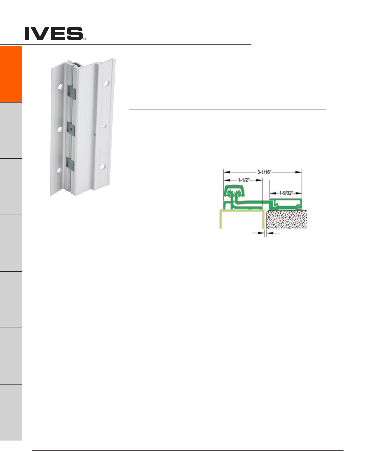
Ives Architectural hardware products
A22
Continuous Hinges
B
Pulls & Plates
A22
Hinges & Pivots
C
Flush Bolts & Coordinators
D
Latches, Catches & Bolts
E
Stops
F
Exterior Hardware
G
Miscellaneous Hardware
210HD Full Surface, Swing Clear
Aluminum Geared Continuous Hinge
• Handing required when modified
• 1/32"DoorInset
• 48"MaximumDoorWidth
• Beveled or Square Edge Doors
For Doors Weighing up to 600 pounds
Standard lengths 83", 85", 95", 120"
Standard Mounting Hardware
12-24 X 1/2" Steel Self Tapping Screws,
1/4-20 X 1-1/2" AL Sex Bolt
1/4-20 X 1" Steel
Shoulder Bolt, 12-24 X 3/4" Steel Self Drilling,
Optional SEC - Security Fasteners Available
Finishes
Clear (CL), Dark Bronze (DB)
Custom Anodizing and Painting are
available, consult factory.
1/16" Clearance for Square Edge Door
3/32" Clearance For Beveled Edge Door
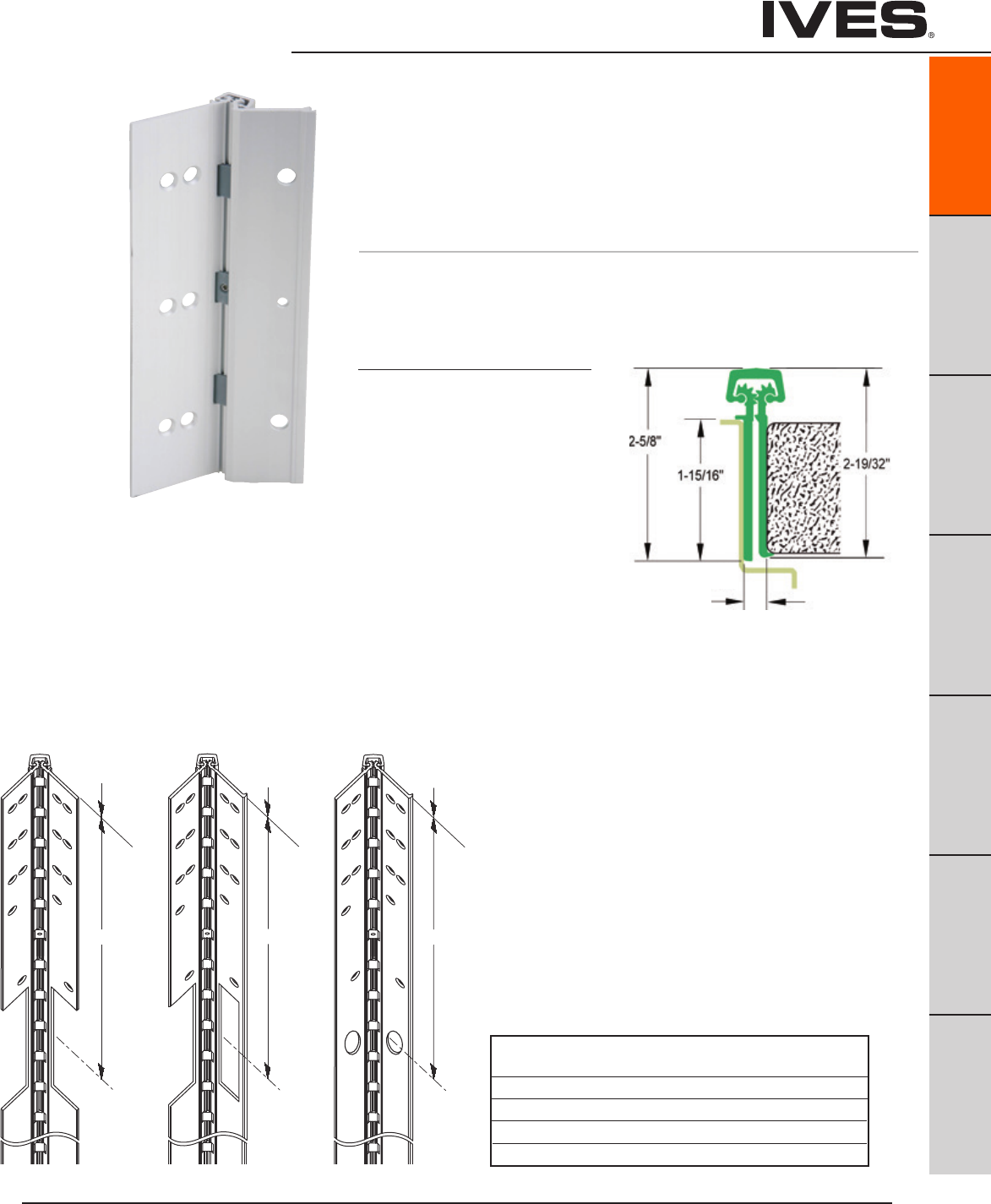
Ives Architectural hardware products
Continuous Hinges
B
Pulls & Plates
A23
Hinges & Pivots
C
Flush Bolts & Coordinators
D
Latches, Catches & Bolts
E
Stops
F
Exterior Hardware
G
Miscellaneous Hardware
A23
Electrical Cutouts
Ives Aluminum Geared Continuous Hinges are available with
factory modified cutouts to accommodate most electrical
frame to door requirements. Special templates are required.
When ordering indicate the following:
1. Opening size.
2. Handing. LH, RH, RHR or LHR.
3. Manufacturer and model number of the electrical product
being used. Example; Von Duprin EPT2
Because clearances may vary between door and frame
manufacturer, and locations can be influenced by the door
hardware it is always recommend contacting Ives Customer
Technical for specific template information.
For your general information below are standard locations
for Von Duprin EPT2 or EPT10, and monitor switch.
224HD Full Mortise Aluminum Geared Continuous Hinge
• Handing required when modified
• DoorEdgeProtector
• 48"MaximumDoorWidth
• 1/16"DoorInset
• Beveled or Square Edge Doors
For Doors Weighing up to 450 pounds without reinforcing,
600 pounds with reinforcing
Standard lengths 83", 85", 95", 120"
Standard Mounting Hardware
12-24 X 3/4" Steel Self Drilling, Self Tapping Screws
Optional WD - Wood Screws or SEC - Security Fasteners Available
Finishes
Clear (CL), Dark Bronze (DB)
Custom Anodizing and Painting are
available, consult factory.
EPT
112HD
112HD 224HD
“C EPT”
L
“C EPT”
L
Top of
hinge/door
Top of
hinge/door
Top of
hinge/door
224HD
112HD
TW
“C TW”
L
112HD 224HD
“C EPT”
L
“C EPT”
L
Top of
hinge/door
Top of
hinge/door
Top of
hinge/door
224HD
112HD
TW
“C TW”
L
EPT
224HD
112HD 224HD
“C EPT”
L
“C EPT”
L
Top of
hinge/door
Top of
hinge/door
Top of
hinge/door
224HD
112HD
TW
“C TW”
L
TW
112HD
224HD
5/16" Clearance for Square Edge Door
1/32" Clearance For Beveled Edge Door
From Top Edge of Door to Center Line of Cut-Out
Standard 112HD 224HD 112HD/224HD
Length EPT EPT TW
83" 30" 30" 41-1/2"
85" 32" 32" 42-1/2"
95" 42" 42" 57-3/4"
120" 67" 67" 81-25/32"
TWP option centered in hinge.
Note: See ordering guide in price book for proper placement.

Ives Architectural hardware products
A24
Continuous Hinges
B
Pulls & Plates
A24
Hinges & Pivots
C
Flush Bolts & Coordinators
D
Latches, Catches & Bolts
E
Stops
F
Exterior Hardware
G
Miscellaneous Hardware
General Information
Standard Lengths
83", 85", 95", 120"
Custom lengths are available up to 120", consult factory.
Finishes
US32D (630) Satin Stainless Steel
USP (600) Steel, Primed for Paint
Barrel Type
Twin Self Lubricated Nylon Bearings with Stainless Steel Pin.
Door Weight
Each hinge can hold a door up to 600 lbs (Rivet nuts recommended) and a max door width of 4'0".
ANSI Certified
All Ives Pin and Barrel Hinges certified to ANSI 156.26, Grade 1.
UL Listed
All Ives Steel and Stainless Steel Pin and Barrel Hinges are tested and approved UL 10C (3 hr).
Field Modifications
All Ives Pin and Barrel Continuous Hinges can be cut to length during installation. If more than 6" from
bottom of hinge, additional modifications may be necessary.
Electrification Options
Only available for the Full Mortise Hinges
Electric Power Transfer (EPT)
Electric power transfer provides a means of transferring power from the door frame to the edge of a
swinging door. Ives Continuous Hinges provide cut outs to fit Von Duprin EPT-2, EPT-10 and
PNT-1 devices. Consult factory for other EPT cut out options.
Electrical Through-Wire (TW)
Provides electric power transfer from the frame to the door in order to supply power to an electrified
mortise or cylindrical locks, exit devices with electric latch retraction, and/or electric strikes (pairs of
doors). Through-wire is rated for 3.5 amp continuous and 16 amp pulse. Ives thru-wire are fully
compatible with 4 wire and 8 wire installations.
Pin and Barrel Hinges
Ives Architectural hardware products
Continuous Hinges
B
Pulls & Plates
A25
Hinges & Pivots
C
Flush Bolts & Coordinators
D
Latches, Catches & Bolts
E
Stops
F
Exterior Hardware
G
Miscellaneous Hardware
A25
How to Order:
Model
Stainless Steel
700 Full Mortise
702 Full Surface - Center Pivot
705 Full Mortise - Full Wrap
711 Full Surface - Swing Clear
715 Full Mortise - Half Wrap
Steel
600 Full Mortise
602 Full Surface - Center Pivot
611 Full Surface - Swing Clear
Finish
Stainless Steel
US32D (630)
Steel
USP (600) Primed
Length
83"
85"
95"
120"
Options
* EPT Electric Power Transfer Prep
* TW8 Electric Through Wire
* TW8M Electric Through Wire + Monitoring
SF Security Fasteners - Torx
WD Wood Fasteners
* Full Mortise Models Only
700 - US32D - 83 - EPT
Pin and Barrel Hinges
Other lengths available up to 120”, consult factory. Handing is required.
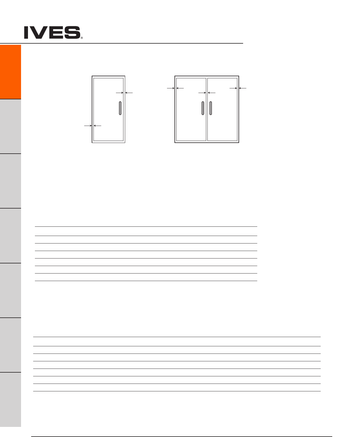
Ives Architectural hardware products
A26
Continuous Hinges
B
Pulls & Plates
A26
Hinges & Pivots
C
Flush Bolts & Coordinators
D
Latches, Catches & Bolts
E
Stops
F
Exterior Hardware
G
Miscellaneous Hardware
SINGLE DOOR
Door Under-Sizing
Hinge-Side Lock-Side Frame Beveled Door Square Beveled
Model Clearance Clearance Irregularity Clearance Edged Edged
600 1/4" 1/8" 1/32" 1/32" 13/32" 7/16"
602 1/8" 1/8" 1/32" 1/32" 9/32" 5/16"
700 1/4" 1/8" 1/32" 1/32" 13/32" 7/16"
702 1/8" 1/8" 1/32" 1/32" 9/32" 5/16"
705 3/8" 1/8" 1/32" 1/32" 17/32" 9/16"
705* 1/2" 1/8" 1/32" 1/32" 21/32" 11/16"
711 7/32" 1/8" 1/32" 1/32" 3/8" 13/32"
715 1/4" 1/8" 1/32" 1/32" 13/32" 7/16"
PAIR OF DOORS
Door Under-Sizing
Square Square Beveled Beveled
Hinge-Side Lock-Side Frame Beveled Door Edged Edged Edged Edged
Model Clearance Clearance Irregularity Clearance Total Each Door Total Each Door
600 1/4" 3/16" 1/16" 1/16" 3/4" 3/8" 13/16" 13/32"
602 1/8" 3/16" 1/16" 1/16" 1/2" 1/4" 9/16" 9/32"
700 1/4" 3/16" 1/16" 1/16" 3/4" 3/8" 13/16" 13/32"
702 1/8" 3/16" 1/16" 1/16" 1/2" 1/4" 9/16" 9/32"
705 3/8" 3/16" 1/16" 1/16" 1" 1/2" 1-1/16" 17/32"
705* 1/2" 3/16" 1/16" 1/16" 1-1/4" 5/8" 1-5/16" 21/32"
711 7/32" 3/16" 1/16" 1/16" 11/16" 11/32" 3/4" 3/8"
715 1/4" 3/16" 1/16" 1/16" 3/4" 3/8" 13/16" 13/32"
Hinge
Side
Clearance
1/32”
Frame
Irregularity
1/8” Hinge
Side
Clearance
Hinge
Side
Clearance
1/16”
Frame
Irregularity
3/16”
Hinge
Side
Clearance
1/32”
Frame
Irregularity
1/8” Hinge
Side
Clearance
Hinge
Side
Clearance
1/16”
Frame
Irregularity
1/8”
705 with Adjusta-Stud
* Use the Adjusta-Studs with 705
* Use the Adjusta-Studs with 705
Pin and Barrel Hinges - Clearance Requirements
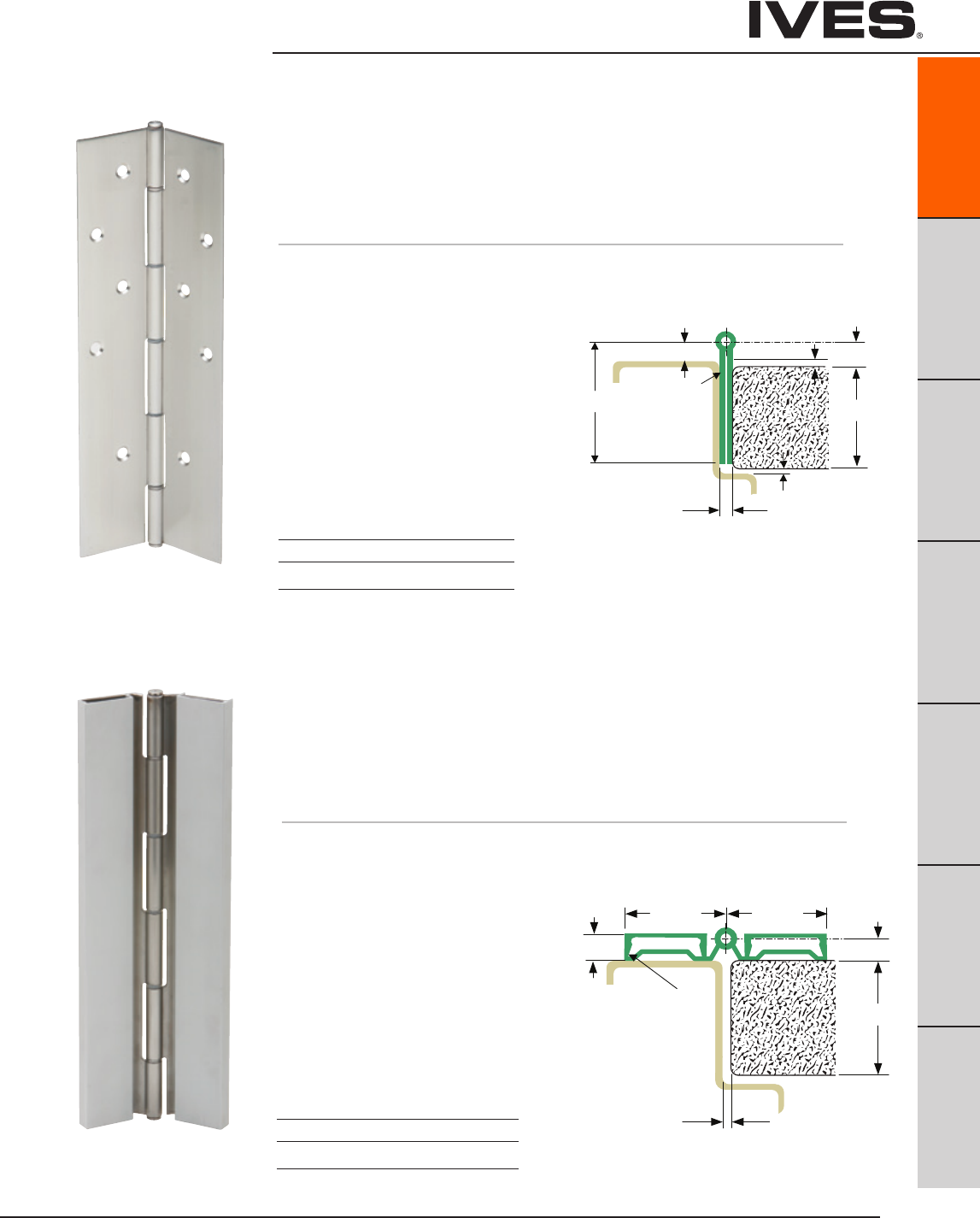
Ives Architectural hardware products
Continuous Hinges
B
Pulls & Plates
A27
Hinges & Pivots
C
Flush Bolts & Coordinators
D
Latches, Catches & Bolts
E
Stops
F
Exterior Hardware
G
Miscellaneous Hardware
A27
” 4 / 3 - 1
” 2 / 1
s s e n k c i h T e g n i H ” 5 7 0 . 0 A G
”4/ 1
” 6 1 / 1
”4/ 1- 2
” 8 / 1
” 8 / 3
007 ,006 ,005 sevI
7/32" [5.6] HINGE ALLOWANCE
2" [50.8]
GA 0.075" HINGE THICKNESS
GA. 0.060"
[1.5]
DOOR
] 3 . 1 [ " 0 5 0 . 0 . A G
] 6 . 1 [ " 6 1 / 1
] 5 . 4 4 [ " 6 1 / 1 1
" 4 / 3
] 1 . 9 1 [
FRAME
" 2 / 1
] 7 . 2 1 [
" 8 / 1
] 5 . 9 [
] 7 . 2 1 [ " 2 / 1
] 5 . 5 5 [ " 6 1 / 3 2
" 8 / 5
] 9 . 5 1 [
" 4 / 3
] 1 . 9 1 [
" 8 / 3
] 5 . 9 [
HINGE
600
700 Full Mortise Pin and Barrel Continuous Hinge
For Doors Weighing up to 600 pounds
• NonHanded
• 1/8”Inset
• 48"MaximumDoorWidth
• NonHanded
• BevelorSquareEdgeDoor
Standard lengths 83", 85", 95", 120"
Standard Mounting Hardware
#10 X 1/2" Self Drilling Self Tapping Screws,
#10 X 1" Wood Screws
Optional SEC - Security Fasteners Available
Material
600- 1012 Cold-Rolled Steel
700- 14 Gauge Type 304 Stainless Steel
1/4" Diameter 304 Stainless Pin with
Nylon Split Bearing
Finishes 600 700
BHMA 600 630
US Numbers USP US32D
Custom Paint Available, on 600
consult factory.
” 4 / 3 - 1
” 8 / 3
”8 / 1
207 ,206 sevI
1/8" MIN. DOOR CLEARENCE
HINGE
DOOR
FRAME
2" [50.8]
] 3 . 1 [ " 0 5 0 . 0 . A G
] 5 . 4 4 [ " 4 / 3 1 " 8 / 3
] 5 . 9 [
GA 0.075" HINGE THICKNESS
" 8 / 3
] 5 . 9 [
GA 0.060"
[1.5]
1-3/4” 1-3/4”
ssenkcihT egniH ”570.0 AG
7/16”
602
702 Full Surface Pin and Barrel Continuous Hinge
For Doors Weighing up to 600 pounds
• NonHanded
• FlushMounted,NoInset
• 48"MaximumDoorWidth
• BevelorSquareEdgeDoor
Standard lengths 83", 85", 95", 120"
Standard Mounting Hardware
1/4"-20 x 3/4" Self Drilling Self Tapping Screws,
Cover Clips
Optional SEC - Security Fasteners Available
Material
602- 1012 Cold-Rolled Steel
702 - 14 Gauge Type 304 Stainless Steel
1/4" Diameter 304 Stainless Pin with
Nylon Split Bearing
Brushed Aluminum Leaf Covers
Finishes 602 702
BHMA 600 630
US Numbers USP US32D
Custom Paint Available, on 602
consult factory
Clearance for
Square Edge
5/16" Clearance for
Beveled Edge
Clearance for
Square Edge
5/32" Clearance for
Beveled Edge
1/8"
Pin and Barrel Hinges - Clearance Requirements
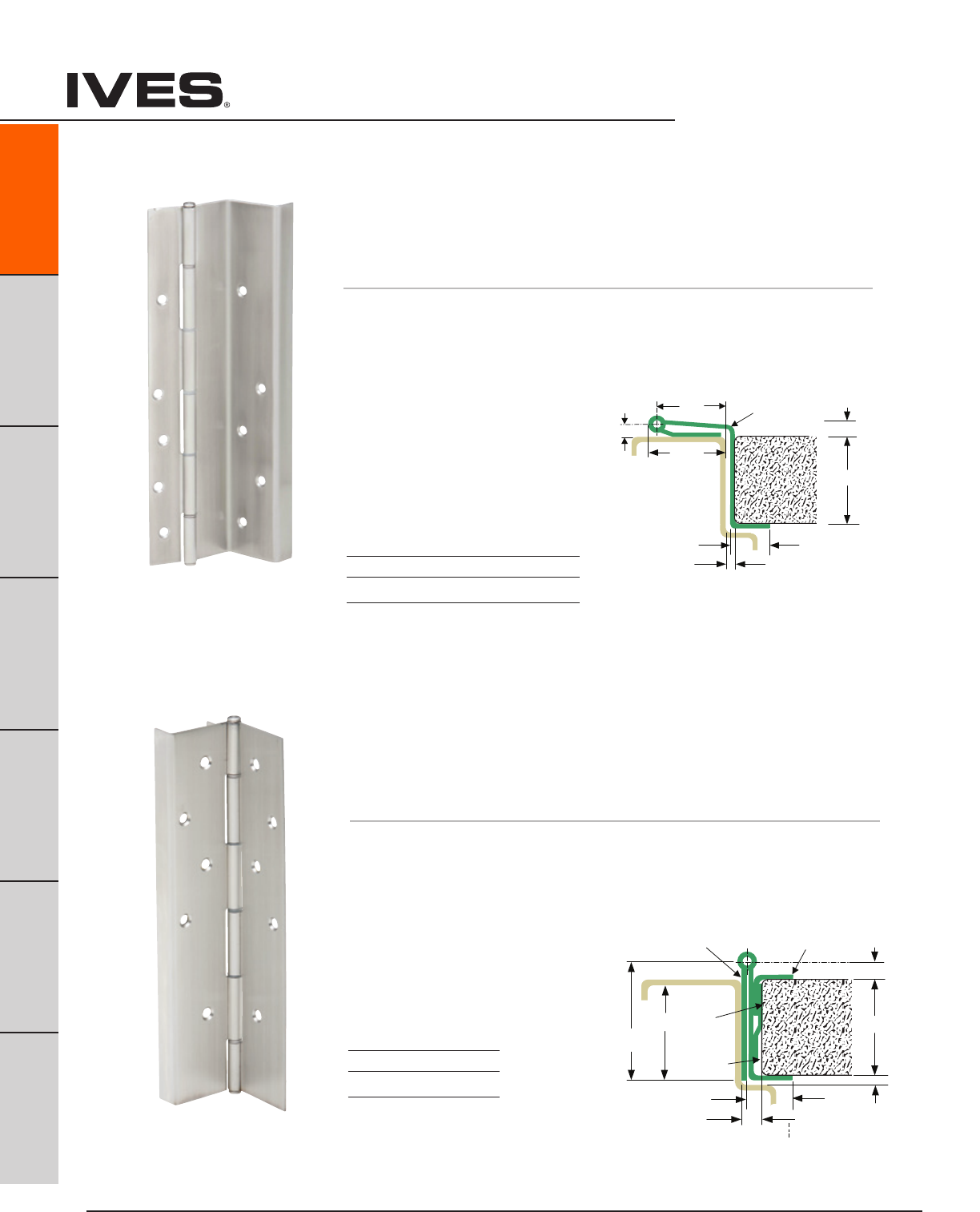
Ives Architectural hardware products
A28
Continuous Hinges
B
Pulls & Plates
A28
Hinges & Pivots
C
Flush Bolts & Coordinators
D
Latches, Catches & Bolts
E
Stops
F
Exterior Hardware
G
Miscellaneous Hardware
” 4 / 3 - 1
”4/1-2
”8/7-1
” 8 / 3
s s e n k c i h T e g n i H ” 5 7 0 . 0 A G
”8/ 3
” 4
3/16”
/ 3
” 5 2 6 0 . 0 A G
”570.0 AG
507 sevI
5/16" [7.9] HINGE ALLOWANCE
" 4 / 3
] 1 . 9 1 [
" 2 / 1
] 7 . 2 1 [
HINGE
DOOR
FRAME
2" [50.8]
0.750"
[19.0]
] 3 . 1 [ " 0 5 0 . 0 . A G
] 5 . 4 4 [ " 4 / 3 1
NOTE: PROVIDE
0.125" ADJUSTMENT
GA 0.075"
GA 0.0625"
] 5 . 9 [ " 8 / 3
" 8 / 5
] 9 . 5 1 [
GA 0.075" HINGE THICKNESS
" 4 / 3
] 1 . 9 1 [
" 8 / 3
] 5 . 9 [
GA 0.060"
[1.5]
Note:
Provide
0.125”
Adjustment
705 Full Moritse, Full Wrap
Pin and Barrel Continuous Hinge
For Doors Weighing up to 600 pounds
• NonHanded
• FlushMounted,NoInset
• 48"MaximumDoorWidth
• FullWrapEdgeGuard
• BevelorSquareEdgeDoor
Standard lengths 83", 85", 95", 120"
Standard Mounting Hardware
#10 X 1/2" Self Drilling Self Tapping Screws, #10 X 1" Wood Screws
Adjusta-stud 1-3/8" with 10-32 internal thread
Optional SEC - Security Fasteners Available.
Material
14 Gauge Type 304 Stainless Steel
1/4" diameter 304 stanless pin with
nylon split bearings
Finishes
BHMA 630
US Numbers US32D
” 4 / 3 - 1
” 8 / 3
” 2 3 / 5
” 4 / 3
e g n i H ” 5 7 0 . 0 A G
s s e n k c i h T
” 4 / 1
” 8 / 3 - 1
”
16
/9-1
117 ,116 sevI
5/32" [4.0] HINGE ALLOWANCE
] 3 . 1 [ " 0 5 0 . 0 . A G " 4 / 3
] 1 . 9 1 [
] 5 . 4 4 [ " 4 / 3 1
HINGE
" 2 / 1
] 7 . 2 1 [
0.750"
[19.0]
5/16"
[7.9]
GA. 0.075" HINGE THICKNESS
1/2"
[12.7]
9/16"
[14.3]
1 3/8" [34.9]
2" [50.8]
" 4 / 1
] 4 . 6 [
FRAME DOOR
GA. 0.060"
[1.5]
611
711 Swing Clear Pin and Barrel Continuous Hinge
For Doors Weighing up to 600 pounds
• NonHanded
• EdgeGuard
• 48"MaximumDoorWidth
• SquareEdgeDoor
Standard lengths 83", 85", 95", 120"
Standard Mounting Hardware
#10 X 1/2" Self Drilling Self Tapping Screws
#10 X 1" Wood Screws
Optional SEC - Security Fasteners
Available
Material
611- 1012 Cold-Rolled Steel
711- 14 Gauge Type 304 Stainless Steel
1/4" diameter 304 stanless pin with
nylon split bearings
Finishes 611 711
BHMA 600 630
US Numbers USP US32D
Custom Paint Available, on 611
consult factory
* Adjusta-Stud allows up to 3/8” width adjustment which ensures proper alignment and easy installation.
Adjusta-Stud also makes it possible for future adjustments of the door on the frame through repositioning.
7/32" Clearance for
Square Edge
1/4" Clearance for
Beveled Edge
3/8" Clearance for
Square Edge
13/32" Clearance for
Beveled Edge
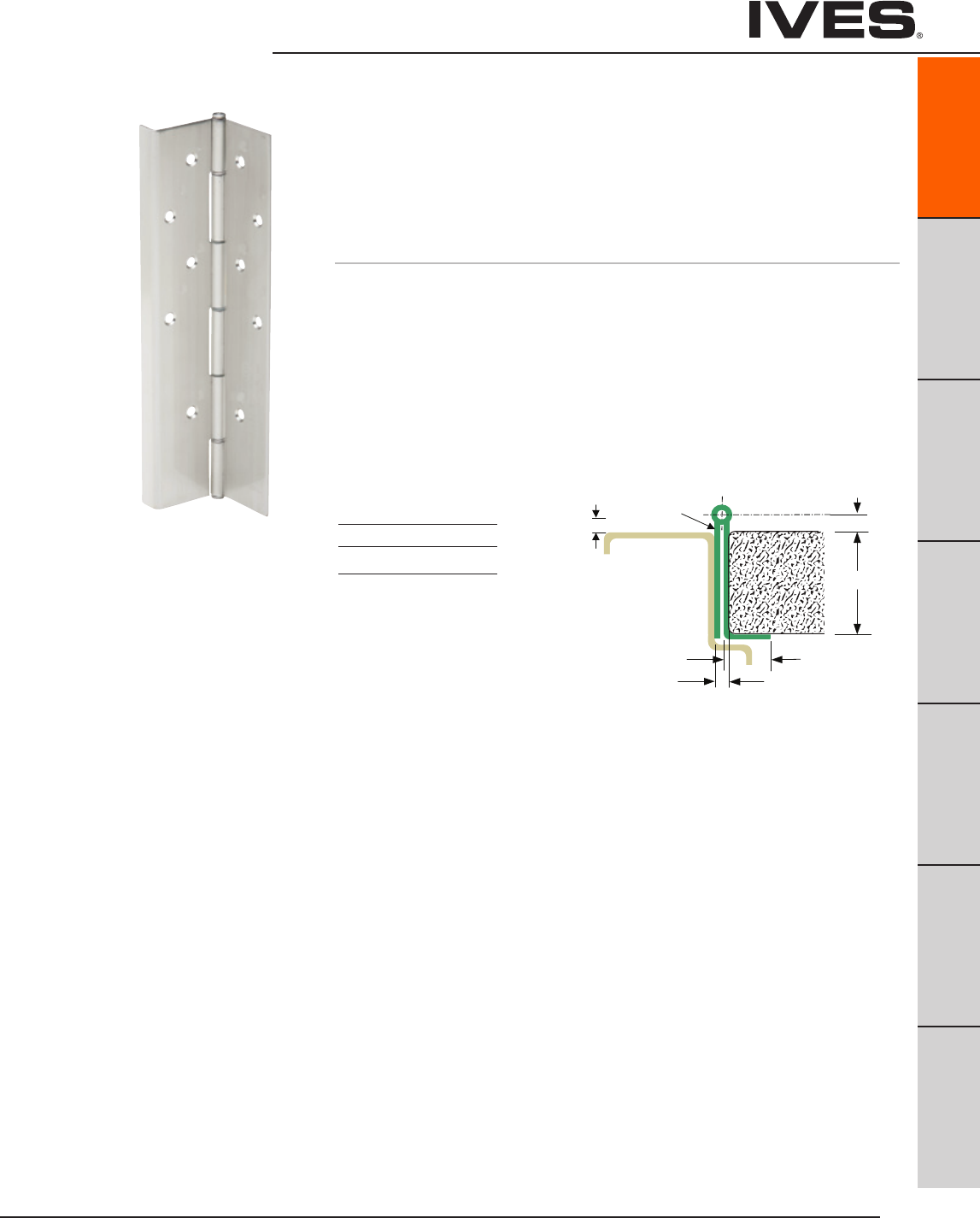
Ives Architectural hardware products
Continuous Hinges
B
Pulls & Plates
A29
Hinges & Pivots
C
Flush Bolts & Coordinators
D
Latches, Catches & Bolts
E
Stops
F
Exterior Hardware
G
Miscellaneous Hardware
A29
” 4 / 3 - 1
” 8 / 3
” 4 / 1
” 4 / 3
e g n i H ” 5 7 0 . 0 A G
s s e n k c i h T
” 4 / 1
517 sevI
1/4" [6.4] HINGE ALLOWANCE
2" [50.8]
] 5 . 4 4 [ " 4 / 3 1
" 4 / 3
] 1 . 9 1 [
HINGE
" 8 / 5
] 9 . 5 1 [
GA 0.075" HINGE THICKNESS
GA 0.060"
[1.5]
" 8 / 3
] 5 . 9 [
DOOR
" 4 / 3
] 1 . 9 1 [
" 2 / 1
] 7 . 2 1 [
0.750"
[19.0]
] 5 . 4 4 [ " 0 5 0 . 0 . A G
FRAME
] 5 . 9 [ " 8 / 3
715 Full Mortise, Half Wrap
Pin and Barrel Continuous Hinge
For Doors Weighing up to 600 pounds
• NonHanded
• FlushMounted,NoInset
• HalfWrapEdgeGuard
• 48"MaximumDoorWidth
• SquareEdgeDoor
Standard lengths 83", 85", 95", 120"
Standard Mounting Hardware
#10 X 1/2" Self Drilling Tek Screws,
#10 X 1" Wood Screws
Optional SEC - Security Fasteners Available
Material
14 Gauge Type 304 Stainless Steel
1/4" diameter 304 stanless pin with
nylon split bearings
Finishes
BHMA 630
US Numbers US32D
Custom Paint Available,
consult factory
1/4" Clearance for
Square Edge
4/32" Clearance for
Beveled Edge
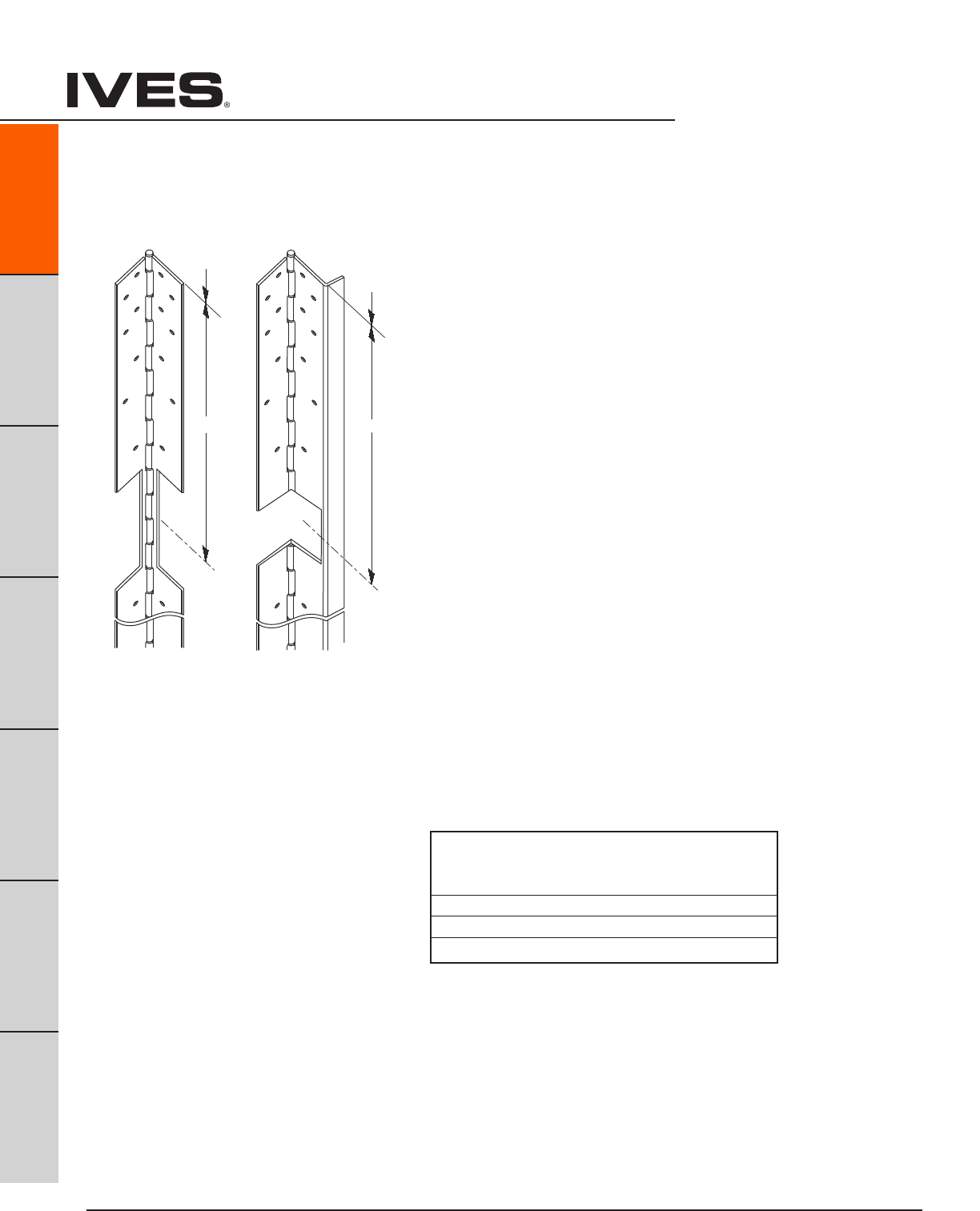
Ives Architectural hardware products
Electrical Cutouts
Ives Pin & Barrel Continuous Hinges are available with factory modified cutouts
to accommodate most electrical frame to door requirements. Special templates
are required.
When ordering indicate the following:
1. Opening size.
2. Handing. LH, RH, RHR or LHR.
3. Manufacturer and model number of the electrical product being used.
Example; Von Duprin EPT2
Because clearances may vary between door and frame manufacturer, and
locations can be influenced by the door hardware it is always recommend
contacting Ives Customer Technical for specific template information.
For your general information following are standard locations for Von Duprin
EPT2 or EPT10, and TW (through wire)
Standard centerline cutout locations
A30
Continuous Hinges
B
Pulls & Plates
A30
Hinges & Pivots
C
Flush Bolts & Coordinators
D
Latches, Catches & Bolts
E
Stops
F
Exterior Hardware
G
Miscellaneous Hardware
Top of door
600/700 600/700 TW
Top of door
“C EPT”
L
“C TW”
L
C = Center line
L
EPT
600/700
Top of door
600/700 600/700 TW
Top of door
“C EPT”
L
“C TW”
L
C = Center line
L
TW
600/700
From Top Edge o top of Door to Center Line of Cut-Out
Standard
Length EPT TW
83" 30" 43-19/32"
85" 32" 45-17/32"
95" 42" 55-17/32"
120" 67" 80-17/32"
Note: See ordering guide in price book for proper placement.
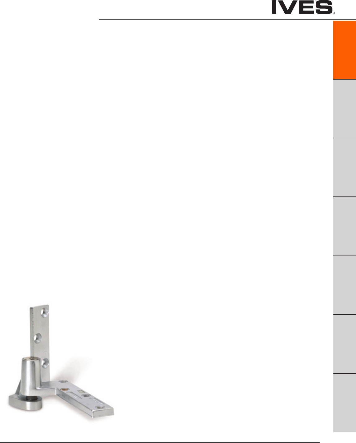
Ives Architectural hardware products
Pivots
B
Pulls & Plates
A31
Hinges & Pivots
C
Flush Bolts & Coordinators
D
Latches, Catches & Bolts
E
Stops
F
Exterior Hardware
G
Miscellaneous Hardware
A31
The door rests on the bottom pivot in this application. This reduces
the stress on the frame by distributing the weight of the door
throughout the floor and structure. By taking advantage of the
strength of the structure, this makes a pivot the ideal solution for
your heavy doors. Center and pocket pivots also provide an aesthetic
option for your opening.
Pivots Table Of Contents
page
General Information .................................................. A32
Selection Chart and Parts Reference .................................. A32
How To Order ........................................................ A33
7212 ......................3/4" Offset ...............................A34
7212V ....................3/4" Offset ...............................A34
7215, 7215F ...............3/4" Offset ...............................A35
7222 .....................3/4" Offset ...............................A36
7226, 7226F ..............3/4" Offset ............................... A37
7227, 7227F ..............3/4" Offset ...............................A38
7230F ....................3/4" Offset ...............................A39
7237F ....................3/4" Offset ...............................A40
7244F ....................1-1/2" Offset ...............................A41
7245F ....................1-1/2" Offset ...............................A42
7212-722V-7222 INT ......Intermediate ..............................A43
7215-7226-7227 INT ......Intermediate ..............................A43
7215F-7226F-7227F INT ...Intermediate ..............................A43
7230F-7237F INT .........Intermediate ..............................A44
7244F-7245F INT .........Intermediate ..............................A44
7215PT-7226PT-7227PT ..Intermediate, Electrified ...................A45
7253 .....................Center Hung ..............................A46
7255 .....................Center Hung .............................. A47
7255J ....................Center Hung .............................. A47
7256 .....................Center Hung ..............................A48
7259 .....................Center Hung ..............................A49
Pocket Pivots
91105 .................................................................A50
91105F ...............................................................A50
Ives Architectural hardware products
A32
Pivots
B
Pulls & Plates
A32
Hinges & Pivots
C
Flush Bolts & Coordinators
D
Latches, Catches & Bolts
E
Stops
F
Exterior Hardware
G
Miscellaneous Hardware
7200 Series Pivots
General Information:
Complete line of 3/4" offset, 1-1/2" offset, center hung, intermediate and
power transfer pivots with all exposed parts made of brass or stainless
steel for maximum corrosion resistance.
High strength brass and stainless steel forgings, and castings for rated
and non-rated doors combined with precision bearings for smooth oper-
ation.
Stainless steel machine screws and wood screws standard. Positive
locking vertical adjustment mechanism allows the installer to precisely
position the door and balance the load.
Last digit in pivot set number reflects the maximum door weight in
hundreds of pound, e.g., 7215 = 500 pounds. For sets designated as
“heavy duty”, add 1,000 pounds, e.g., 7237F HD set = 1700 pounds. Pivots
for lead lined doors are available, consult factory.
Pivot Pivot Type Bottom Mounting UL Listing Max. Door Handing When Ordering Separate Parts
Set Style Weight Top Bottom Intermediate
7212 3/4" Offset Jamb Mounted none 200 LH or RH 7212-7215-7222-7226-7227 TOP 7212 BTM 7212-7212V-7222 INT
7212V 3/4" Offset Jamb Mounted none 200 LH or RH 7212V TOP 7212 BTM 7212-7212V-7222 INT
7215 3/4" Offset Jamb Mounted 20 Minute 500 LH or RH 7212-7215-7222-7226-7227 TOP 7215 BTM 7215-7226-7227 INT
7215F 3/4" Offset Jamb Mounted 3 Hour 500 LH or RH 7215F-7226F-7227F TOP 7215F BTM 7215F-7226F-7227F INT
7222 3/4" Offset Floor Mounted none 200 LH or RH 7212-7215-7222-7226-7227 TOP 7222 BTM 7212-7212V-7222 INT
7226 3/4" Offset Floor Mounted 20 Minute 600 Non-Handed 7212-7215-7222-7226-7227 TOP 7226 BTM 7215-7226-7227 INT
7226F 3/4" Offset Floor Mounted 3 Hour 600 Non-Handed 7215F-7226F-7227F TOP 7226F BTM 7215F-7226F-7227F INT
7227 3/4" Offset Mortise Cement Case 20 Minute 700 Non-Handed 7212-7215-7222-7226-7227 TOP 7227 BTM 7215-7226-7227 INT
7227F 3/4" Offset Mortise Cement Case 3 Hour 700 Non-Handed 7215F-7226F-7227F TOP 7227F BTM 7215-7226-7227 INT
7230F 3/4" Offset Floor Mounted 3 Hour 1,000 Non-Handed 7230F-7237F TOP 7230F BTM 7215F-7226F-7227F INT
7237F 3/4" Offset Mortise Cement Case 3 Hour 1,750 Non-Handed 7230F-7237F TOP 7237F BTM 7230F-7237F INT
7244F 1-1/2" Offset Floor Mounted 3 Hour 400 Non-Handed 7244F-7245F TOP 7244F BTM 7230F-7237F INT
7245F 1-1/2" Offset Mortise Cement Case 3 Hour 500 Non-Handed 7244F-7245F TOP 7245F BTM 7244F-7245F INT
7253 Center Hung Floor Mounted none 300 Non-Handed 7253-7255-7255J-7256 TOP 7253 BTM 7244F-7245F INT
7255 Center Hung Floor Mounted none 500 Non-Handed 7253-7255-7255J-7256 TOP 7255 BTM none
7255J Center Hung Jamb Mounted none 500 Non-Handed 7253-7255-7255J-7256 TOP 7255J BTM none
7256 Center Hung Mortise Cement Case none 600 Non-Handed 7253-7255-7255J-7256 TOP 7256 BTM none
7259 Center Hung Mortise Cement Case none 1,000 Non-Handed 7259 TOP 7259 BTM none
7200 series Pivot Selection Chart

Ives Architectural hardware products
Pivots
B
Pulls & Plates
A33
Hinges & Pivots
C
Flush Bolts & Coordinators
D
Latches, Catches & Bolts
E
Stops
F
Exterior Hardware
G
Miscellaneous Hardware
A33
How to Order:
Pivot:
7212
7212V
7215
7215F
7222
7226
7226F
7227
7227F
7230F
7237F
7244F
7245F
7253
7255
7255J
7256
7259
Pivot Style:
Blank Top and bottom set
TOP Top pivot only
BTM Bottom pivot only
INT Intermediate pivot only
PT INT Power transfer intermediate pivot only
Hand:
LH Left hand door
RH Right hand door
Finish:
US3
US4
US10
US10B
US26
US26D
SP4
SP10
SP28
SP313
SPBLK
USP
optional finishes are available, consult factory
7212 - - LH - US3
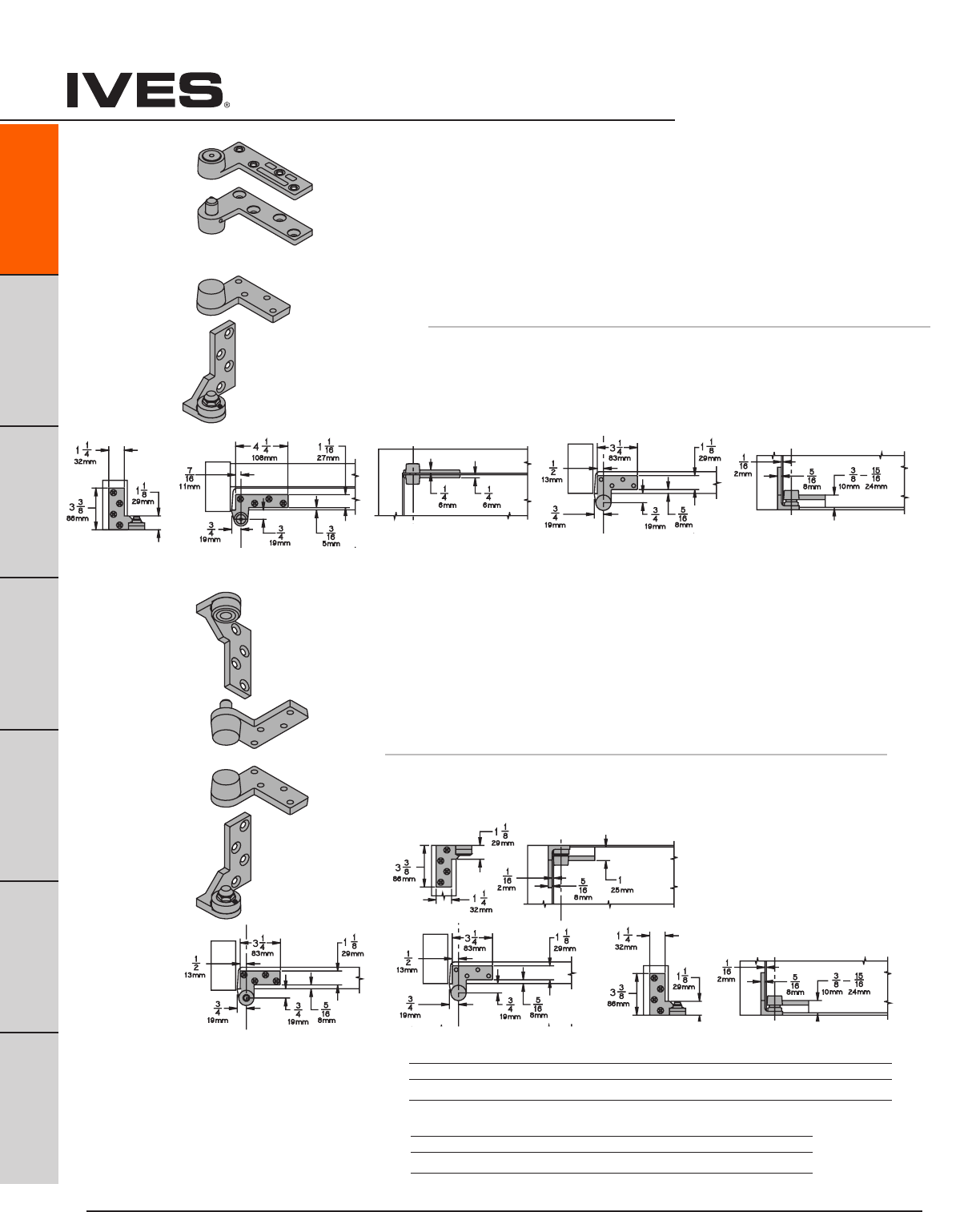
Ives Architectural hardware products
A34
Pivots
B
Pulls & Plates
A34
Hinges & Pivots
C
Flush Bolts & Coordinators
D
Latches, Catches & Bolts
E
Stops
F
Exterior Hardware
G
Miscellaneous Hardware
7212V Pivot Set
7212V Pivot Set
7212V Pivot Set
7212V Pivot Set
7212V Pivot Set
7212 Pivot Set
7212 3/4" Offset Pivot
• Handed
• Top,headermount
• Bottom,jambmount
• Usewith1-3/4"minimumdoorthickness,with1/8"bevelin2"
• Maximumdoorload200pounds
• Verticaladjustmentrange3/16",withpositivelocking
Optional 7212-7212V-7222 Intermediate Pivot (handed) for each
additional 100 pounds or doors over 7'. See page A47.
7212V 3/4" Offset Pivot
• Handed
• Top,jambmount
• Bottom,jambmount
• Usewith1-3/4"minimumdoorthickness,with1/8"bevelin2"
• Maximumdoorload200pounds
• Verticaladjustmentrange3/16",withpositivelocking
Optional 7212-7212V-7222 Intermediate Pivot (handed) for each
additional 100 pounds or doors over 7'. See page A47.
7212 Pivot Set
7212 Pivot Set
7212 Pivot Set
7212 Pivot Set
7212 Pivot Set
Plated Finishes brass
US Number US3 US4 US10 US10B US26 US26D
BHMA Number 605 606 612 613 625 626
Painted Finishes brass
US Number SP4 SP10 SP28 SP313 SPBLK
BHMA Number 706 691 689 695 622
Meets ANSI/BHMA A156.4 C07131

Ives Architectural hardware products
Pivots
B
Pulls & Plates
A35
Hinges & Pivots
C
Flush Bolts & Coordinators
D
Latches, Catches & Bolts
E
Stops
F
Exterior Hardware
G
Miscellaneous Hardware
A35
7215 Pivot Set
7215F Pivot Set
7215 Pivot Set
7215F Pivot Set
7215 Pivot Set
7215F Pivot Set
7215 Pivot Set
7215F Pivot Set
7215 Pivot Set
7215F Pivot Set
7215 Pivot Set
7215F Pivot Set
7215 - Ul Listed 20 minute fire doors
7215F - UL Listed 3 hour fire doors
7215
7215F 3/4" Offset Pivot
• Handed
• Top,headermount
• Bottom,jambmount
• Usewith1-3/4"minimumdoorthickness,with1/8"bevelin2"
• Maximumdoorload500pounds
• Verticaladjustmentrange3/16",withpositivelocking
• WP-optionalweatherresistantbottompivotismodifiedfor
improved corrosion resistance. Available in US26D (626) or
US32D (630) only.
Optional 7215-7226-7227 or 7215F-7226F-7227F Intermediate Pivot
(handed) for each additional 100 pounds or doors over 7'. See page A47.
Optional 7215PT Power Transfer, non-load bearing. See page A49
7215
Plated Finishes brass
US Number US3 US4 US10 US10B US26 US26D
BHMA Number 605 606 612 613 625 626
Painted Finishes brass
US Number SP4 SP10 SP28 SP313 SPBLK
BHMA Number 706 691 689 695 622
7215F
Plated Finishes steel
US Number US3 US10 US32 US32D
BHMA Number 632 639 629 630
Painted Finishes steel
US Number SP4 SP10 SP28 SP313 SPBLK
BHMA Number 706 691 689 695 622
Meets ANSI/BHMA A156.4 C07131
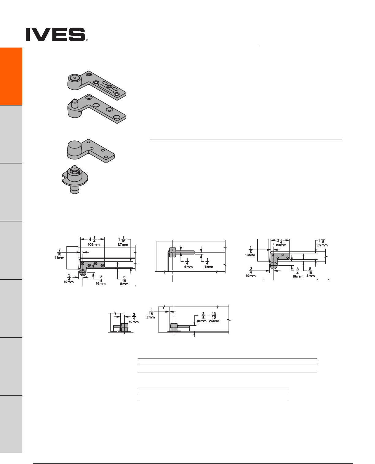
Ives Architectural hardware products
A36
Pivots
B
Pulls & Plates
A36
Hinges & Pivots
C
Flush Bolts & Coordinators
D
Latches, Catches & Bolts
E
Stops
F
Exterior Hardware
G
Miscellaneous Hardware
7222 Pivot Set
7222 Pivot Set
7222 Pivot Set
7222 Pivot Set
7222 Pivot Set
7222 3/4" Offset Pivot
• Handed
• Top,headermount
• Bottom,baseplatemount
• Usewith1-3/4"minimumdoorthickness,with1/8"bevelin2"
• Maximumdoorload200pounds
• Verticaladjustmentrange3/16",withpositivelocking
Optional 7212-7212V-7222 Intermediate Pivot (handed) for each
additional 100 pounds or doors over 7'. See page A47.
Plated Finishes brass
US Number US3 US4 US10 US10B US26 US26D
BHMA Number 605 606 612 613 625 626
Painted Finishes brass
US Number SP4 SP10 SP28 SP313 SPBLK
BHMA Number 706 691 689 695 622
Meets ANSI/BHMA A156.4 C07162
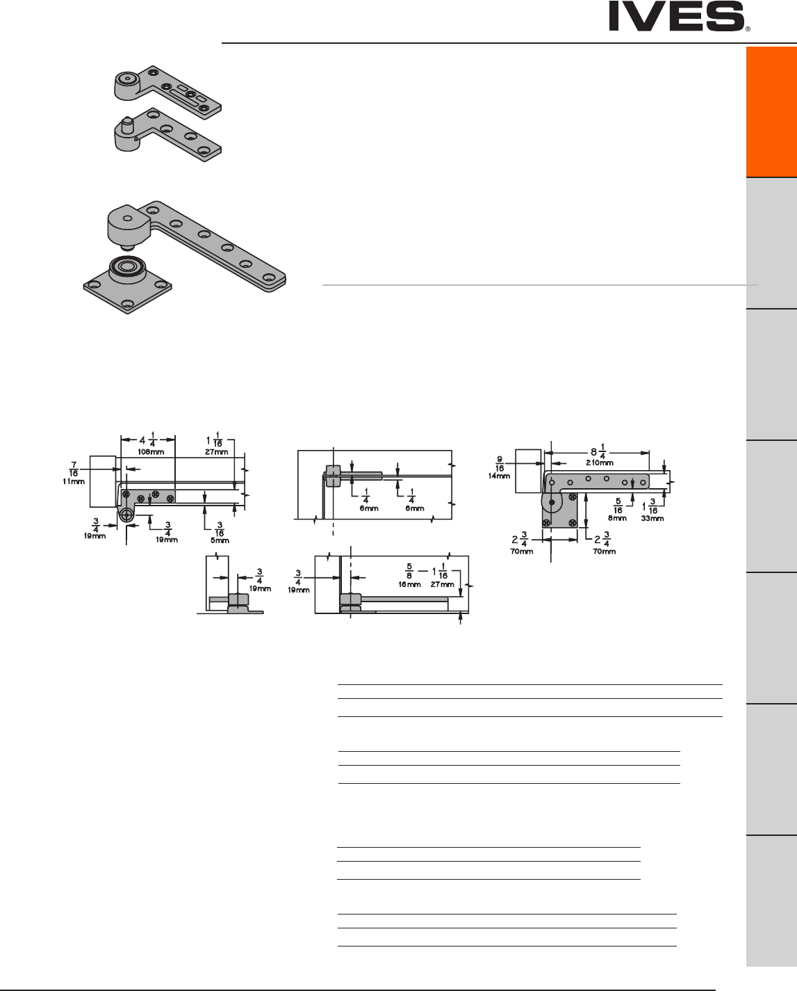
Ives Architectural hardware products
Pivots
B
Pulls & Plates
A37
Hinges & Pivots
C
Flush Bolts & Coordinators
D
Latches, Catches & Bolts
E
Stops
F
Exterior Hardware
G
Miscellaneous Hardware
A37
7226 Pivot Set
7226F Pivot Set
7226 Pivot Set
7226F Pivot Set
7226 Pivot Set
7226F Pivot Set
7226 Pivot Set
7226F Pivot Set
7226 Pivot Set
7226F Pivot Set
7226
7226F 3/4" Offset Pivot
• Non-handed
• Top,headermount
• Bottom,baseplatemount
• Usewith1-3/4"minimumdoorthickness,with1/8"bevelin2"
• Maximumdoorload600pounds
• Verticaladjustmentrange3/16",withpositivelocking
Optional 7215-7226-7227or 7226F-722 Intermediate Pivot (handed) for each
additional 100 pounds or doors over 7'. See page A47.
Optional 7226PT Power Transfer (four wires), non-load bearing. See page A49
7226 - Ul Listed 20 minute fire doors
7226F - UL Listed 3 hour fire doors
7226
Plated Finishes brass
US Number US3 US4 US10 US10B US26 US26D
BHMA Number 605 606 612 613 625 626
Painted Finishes brass
US Number SP4 SP10 SP28 SP313 SPBLK
BHMA Number 706 691 689 695 622
7226F
Plated Finishes steel
US Number US3 US10 US32 US32D
BHMA Number 632 639 629 630
Painted Finishes steel
US Number SP4 SP10 SP28 SP313 SPBLK
BHMA Number 706 691 689 695 622
Meets ANSI/BHMA A156.4 C07162
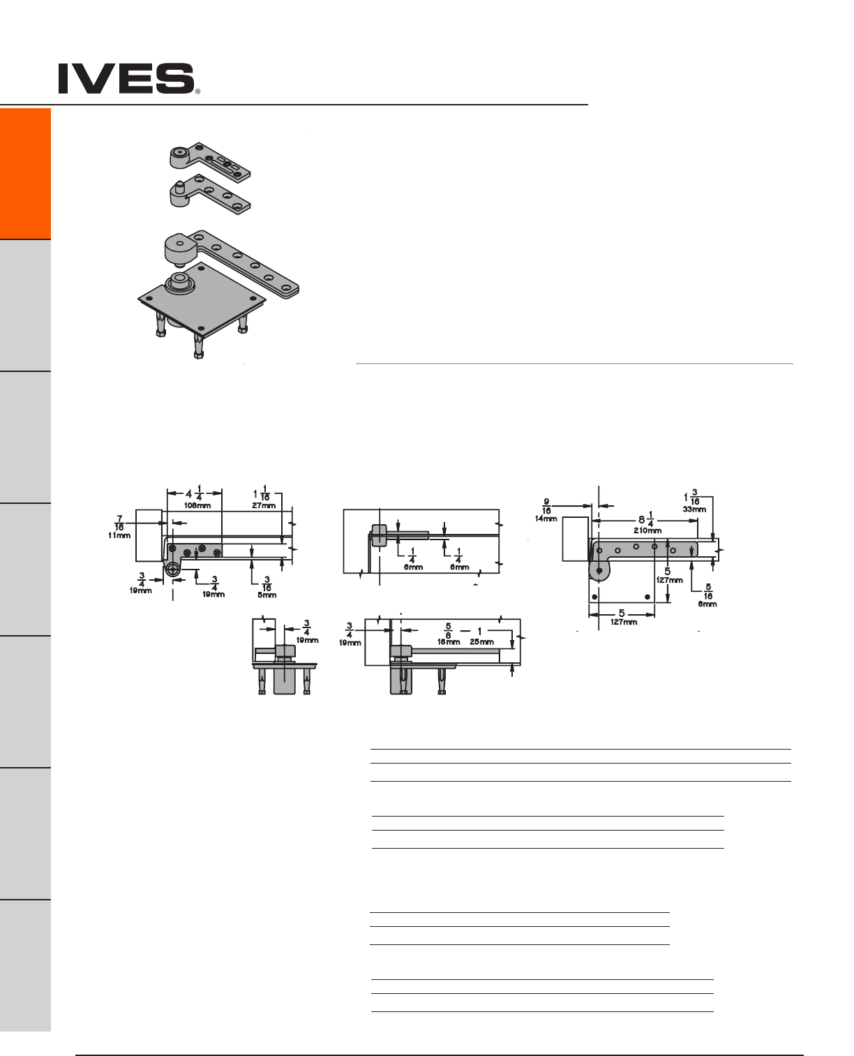
Ives Architectural hardware products
A38
Pivots
B
Pulls & Plates
A38
Hinges & Pivots
C
Flush Bolts & Coordinators
D
Latches, Catches & Bolts
E
Stops
F
Exterior Hardware
G
Miscellaneous Hardware
7227 Pivot Set
7227F Pivot Set
7227 Pivot Set
7227F Pivot Set
7227 Pivot Set
7227F Pivot Set
7227 Pivot Set
7227F Pivot Set
7227 Pivot Set
7227F Pivot Set
7227
7227F 3/4" Offset Pivot
• Non-handed
• Top,headermount
• Bottom,baseplatemount
• Usewith1-3/4"minimumdoorthickness,with1/8"bevelin2"
• Maximumdoorload700pounds
• Verticaladjustmentrange3/16",withpositivelocking
Optional 7215-7226-7227 or 7215F-7226F-7227F Intermediate Pivot (handed) for
each additional 100 pounds or doors over 7'. See page A47.
Optional 7227PT Power Transfer (four wires), non-load bearing. See page A49.
7227 - Ul Listed 20 minute fire doors
7227F - UL Listed 3 hour fire doors
7227
Plated Finishes brass
US Number US3 US4 US10 US10B US26 US26D
BHMA Number 605 606 612 613 625 626
Painted Finishes brass
US Number SP4 SP10 SP28 SP313 SPBLK
BHMA Number 706 691 689 695 622
7227F
Plated Finishes steel
US Number US3 US10 US32 US32D
BHMA Number 632 639 629 630
Painted Finishes steel
US Number SP4 SP10 SP28 SP313 SPBLK
BHMA Number 706 691 689 695 622
Meets ANSI/BHMA A156.4 C07121
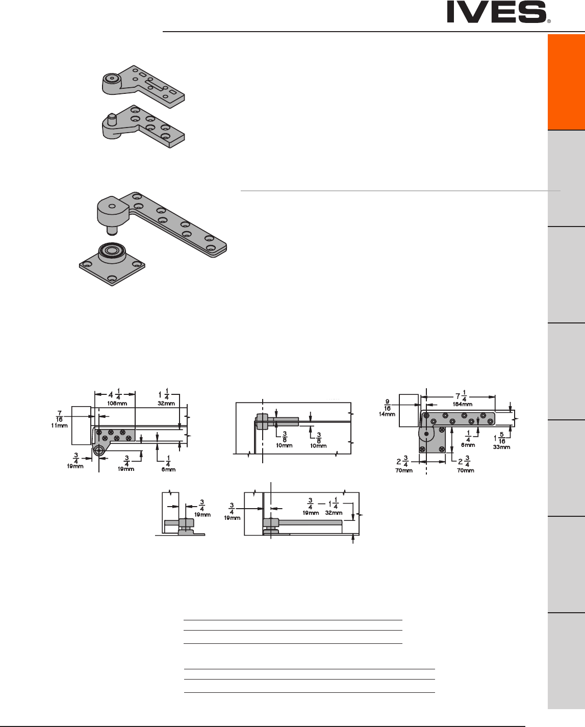
Ives Architectural hardware products
Pivots
B
Pulls & Plates
A39
Hinges & Pivots
C
Flush Bolts & Coordinators
D
Latches, Catches & Bolts
E
Stops
F
Exterior Hardware
G
Miscellaneous Hardware
A39
7230F Pivot Set
7230F Pivot Set
7230F Pivot Set
7230F Pivot Set
7230F Pivot Set
7230F 3/4" Offset Pivot - Heavy Duty
• Non-Handed
• Top,headermount
• Bottom,baseplatemount
• Usewith1-3/4"minimumdoorthickness,with1/8"bevelin2"
• Maximumdoorload1,000pounds
• Verticaladjustmentrange3/16",withpositivelocking
Optional 7230F-7237F Intermediate Pivot (handed) for each
additional 100 pounds or doors over 7'. See page A48.
Meets ANSI/BHMA A156.4 C07162
UL Listed 3 Hour Fire Doors
Plated Finishes steel
US Number US3 US10 US32 US32D
BHMA Number 632 639 629 630
Painted Finishes steel
US Number SP4 SP10 SP28 SP313 SPBLK
BHMA Number 706 691 689 695 622
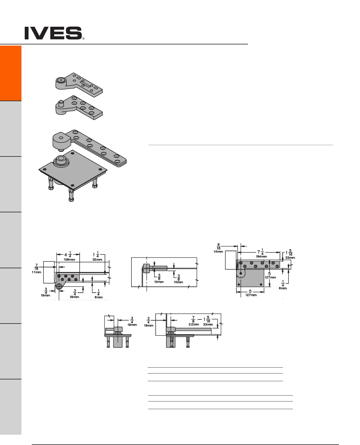
Ives Architectural hardware products
A40
Pivots
B
Pulls & Plates
A40
Hinges & Pivots
C
Flush Bolts & Coordinators
D
Latches, Catches & Bolts
E
Stops
F
Exterior Hardware
G
Miscellaneous Hardware
7237F Pivot Set
7237F Pivot Set
7237F Pivot Set
7237F Pivot Set
7237F Pivot Set
7237F 3/4" Offset Pivot - Heavy Duty
• Non-Handed
• Top,headermount
• Bottom,mortisedcementcasemount
• Usewith1-3/4"minimumdoorthickness,with1/8"bevelin2"
• Maximumdoorload1,750pounds
• Verticaladjustmentrange3/16",withpositivelocking
Optional 7230F-7237F Intermediate Pivot (handed) for each
additional 100 pounds or doors over 7'. See page A48.
Meets ANSI/BHMA A156.4 C07111
UL Listed 3 Hour Fire Doors
Plated Finishes steel
US Number US3 US10 US32 US32D
BHMA Number 632 639 629 630
Painted Finishes steel
US Number SP4 SP10 SP28 SP313 SPBLK
BHMA Number 706 691 689 695 622
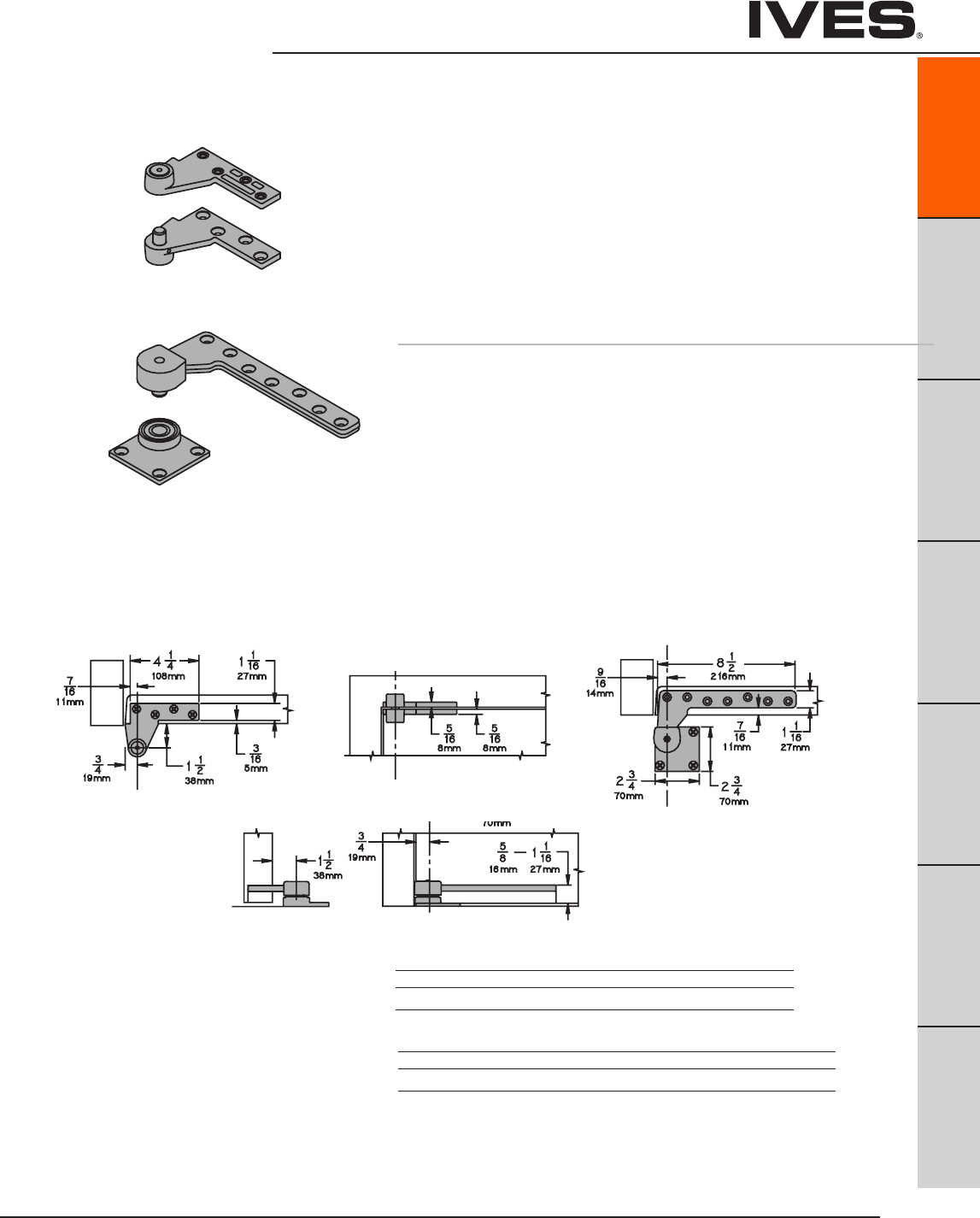
Ives Architectural hardware products
Pivots
B
Pulls & Plates
A41
Hinges & Pivots
C
Flush Bolts & Coordinators
D
Latches, Catches & Bolts
E
Stops
F
Exterior Hardware
G
Miscellaneous Hardware
A41
Meets ANSI/BHMA A156.4 C07162
UL Listed 3 Hour Fire Doors
7244F 1-1/2" Offset Pivot - Heavy Duty
• Non-Handed
• Top,headermount
• Bottom,basemount
• Usewith1-3/4"minimumdoorthickness
• Maximumdoorload400pounds
• Verticaladjustmentrange3/16",withpositivelocking
Optional 7244F-7245F Intermediate Pivot (handed) for each
additional 100 pounds or doors over 7'. See page A48.
Plated Finishes steel
US Number US3 US10 US32 US32D
BHMA Number 632 639 629 630
Painted Finishes steel
US Number SP4 SP10 SP28 SP313 SPBLK
BHMA Number 706 691 689 695 622

Ives Architectural hardware products
A42
Pivots
B
Pulls & Plates
A42
Hinges & Pivots
C
Flush Bolts & Coordinators
D
Latches, Catches & Bolts
E
Stops
F
Exterior Hardware
G
Miscellaneous Hardware
7245F Pivot Set
7245F Pivot Set
7245F Pivot Set
7245F Pivot Set
7245F Pivot Set
Meets ANSI/BHMA A156.4 C07121
UL Listed 3 Hour Fire Doors
7245F 1-1/2" Offset Pivot - Heavy Duty
• Non-Handed
• Top,headermount
• Bottom,mortisedcementcasemount
• Usewith1-3/4"minimumdoorthickness,with1/8"bevelin2"
• Maximumdoorload500pounds
• Verticaladjustmentrange3/16",withpositivelocking
Optional 7244F-7245F Intermediate Pivot (handed) for each
additional 100 pounds or doors over 7'. See page A48.
Plated Finishes steel
US Number US3 US10 US32 US32D
BHMA Number 632 612 629 630
Painted Finishes steel
US Number SP4 SP10 SP28 SP313 SPBLK
BHMA Number 706 691 689 695 622

Ives Architectural hardware products
Intermediate Pivots
B
Pulls & Plates
A43
Hinges & Pivots
C
Flush Bolts & Coordinators
D
Latches, Catches & Bolts
E
Stops
F
Exterior Hardware
G
Miscellaneous Hardware
A43
Intermediate Pivot
7212V-7222 INT
Intermediate Pivot
7212V-7222 INT
Intermediate Pivot
7212V-7222 INT
Intermediate Pivot
7212V-7222 INT
Intermediate Pivot
7215-7226-7227 INT
7215F-7226F-7227F INT
Intermediate Pivot
7215-7226-7227 INT
7215F-7226F-7227F INT
Intermediate Pivot
7215-7226-7227 INT
7215F-7226F-7227F INT
Intermediate Pivot
7215-7226-7227 INT
7215F-7226F-7227F INT
NFPA 80, Section 3-3.8 requires intermediate pivot on some fire door applications, con-
sult factory. Use for door heights over 7'0" and one every 2'6" or . Use for door weight
over the pivot set limit. One additional for every additional 100 pounds. Door thickness
1-3/4" mimumum with 1/8" bevel in 2".
7212-7212V-7222 INT
• Usewith7212,7212Vor72223/4OffsetPivot
• Handed
• Verticaladjustment3/16",includepositivelocking.
7215-7226-7227 INT
• Usewith7215,7226or72273/4OffsetPivot
• Handed
• Verticaladjustment3/16",includepositivelocking.
7215F-7226F-7227F INT
• Usewith7215F,7226For7227F3/4OffsetPivot
• Handed
• Verticaladjustment3/16",includepositivelocking.
7215-7226-7227 INT:
UL listed 20 minute fire doors
Meets ANSI/BHMA A156.4 C07321
7215F-7226F-7227F INT:
UL listed 3 hour fire doors
Meets ANSI/BHMA A156.4 C07371
Meets ANSI/BHMA A156.4 C07382
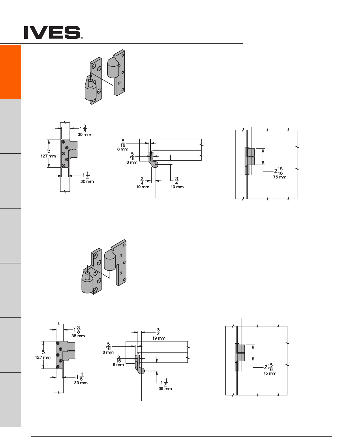
Ives Architectural hardware products
A44
Intermediate Pivots
B
Pulls & Plates
A44
Hinges & Pivots
C
Flush Bolts & Coordinators
D
Latches, Catches & Bolts
E
Stops
F
Exterior Hardware
G
Miscellaneous Hardware
Intermediate Pivot
7244F-7245F INT
Intermediate Pivot
7244F-7245F INT
Intermediate Pivot
7244F-7245F INT
Intermediate Pivot
7244F-7245F INT
Intermediate Pivot
7230F-7237F INT
Intermediate Pivot
7230F-7237F INT
Intermediate Pivot
7230F-7237F INT
Intermediate Pivot
7230F-7237F INT
UL listed 3 hour fire doors
Meets ANSI/BHMA A156.4 C07311
UL listed 3 hour fire doors
Meets ANSI/BHMA A156.4 C07371
7230F-7237F INT
• Usewith7230For7237F3/4OffsetPivot
• Handed
• Verticaladjustment3/16",includepositivelocking.
7244F-7245F
• Usewith7244For7245F1-1/2"OffsetPivot
• Handed
• Verticaladjustment3/16",includepositivelocking.
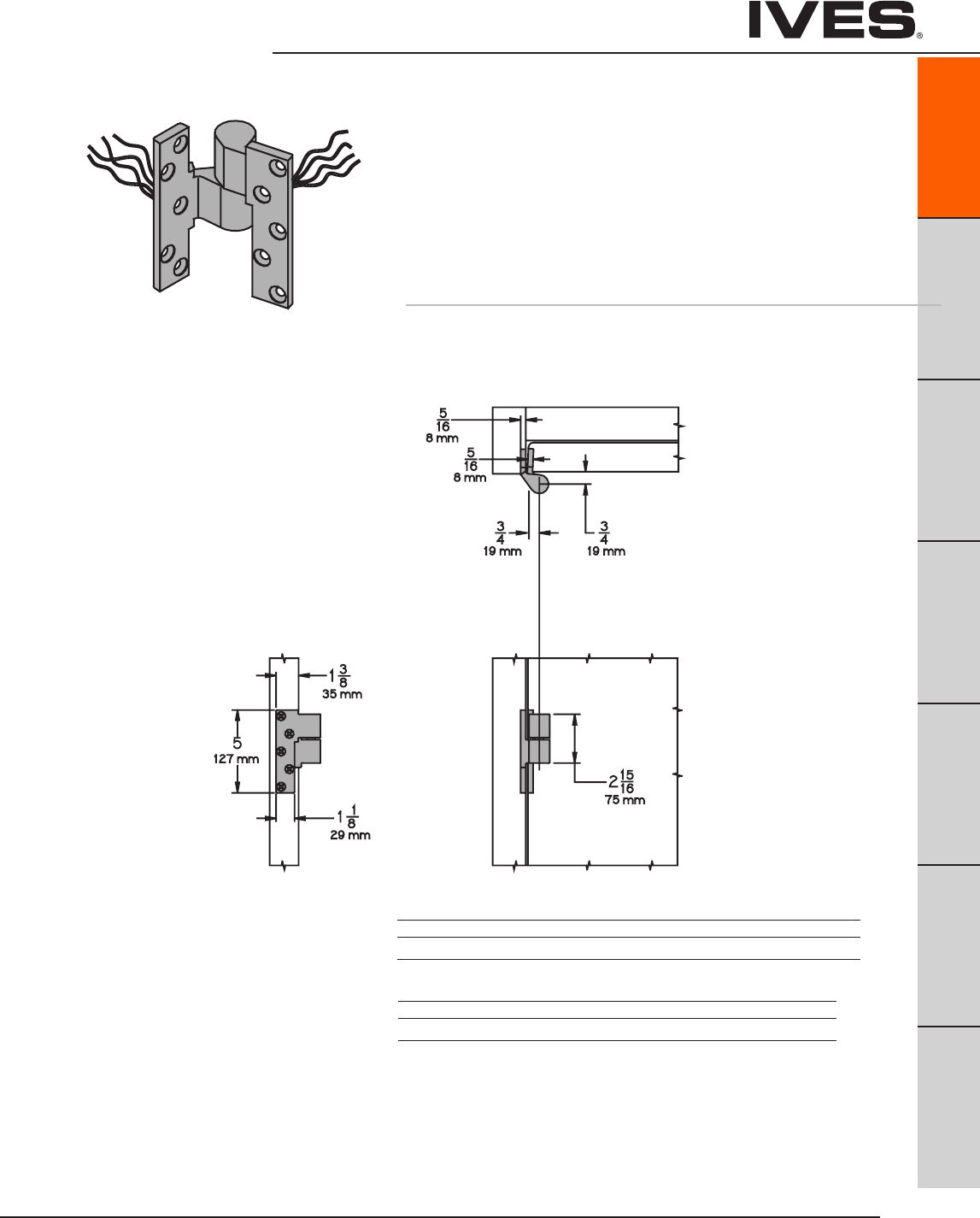
Ives Architectural hardware products
Pivots
B
Pulls & Plates
A45
Hinges & Pivots
C
Flush Bolts & Coordinators
D
Latches, Catches & Bolts
E
Stops
F
Exterior Hardware
G
Miscellaneous Hardware
A45
Power Transfer Intermediate Pivot
7215-7226-7227 PT
Power Transfer Intermediate Pivot
7215-7226-7227 PT
7215PT-7226PT-7227PT Power Transfer Pivot
• Usewith7215,7226or72273/4"OffsetPivots
• Fourwires,28gauge
• Optional8wireavailable
• Rated50VDCorVAC@3.5amps.Continuousor
16 amps pulse, maximum pulse 400 milliseconds.
• Non-loadbearing
• Usewith1-3/4"thickdoorminimum,1/8"bevelin2".
Plate Finishes brass
US Number US3 US4 US10 US10B US26 US26D
BHMA Number 605 606 612 613 625 626
Painted Finishes brass
US Number SP4 SP10 SP28 SP313 SPBLK
BHMA Number 706 691 689 695 622
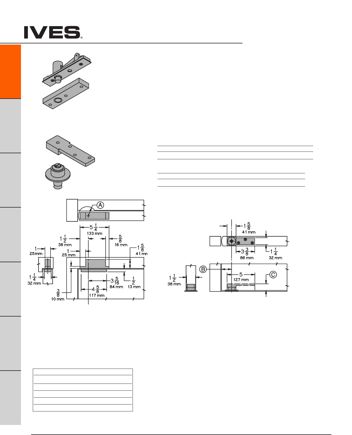
Ives Architectural hardware products
A46
Pivots
B
Pulls & Plates
A46
Hinges & Pivots
C
Flush Bolts & Coordinators
D
Latches, Catches & Bolts
E
Stops
F
Exterior Hardware
G
Miscellaneous Hardware
7253 Pivot Set
7253 Pivot Set
7253 Pivot Set
Table D
Clearance Depth of Mortise
3/16" (5mm) 1-3/16" (30mm)
3/8" (10mm) 1" (25mm)
1/2" (13mm) 7/8" (22mm)
5/8" (16mm) 3/4" (19mm)
3/4" (19mm) 5/8" (16mm)
7253 Center Hung Pivot
• Non-Handed
• Top,headermount
• Bottom,baseplatemount
• Easyinstallationtiltonbearingandbearingpin.
• Usewith1-3/4"minimumdoorthickness.
• Adjustablefloortodoorclearance3/16"to3/4".
• Maximumdoorload300pounds
• Verticaladjustmentrange3/16",withpositivelocking
• RadiusStop(A)toclearheelofdooredge.
• Pivotdistance(B)1-3/4"(44mm)minimumfromjambtocenterlineofpivotpin.Radiusheel
edge of door, 1-5/8" (41mm) minimum recommended.
• Clearancefrombottomedgeofdoortofloormountingsurfaceisadjustablefrom3/16"(5mm)
to 3/4" (19mm) by varying the depth of the mortise (C ) in the bottom of the door, refer to
Chart D. Consult factory when clearance is over 3/4" (19mm).
Plated Finishes brass
US Number US3 US4 US10 US10B US26 US26D
BHMA Number 605 606 612 613 625 626
Painted Finishes brass
US Number SP4 SP10 SP28 SP313 SPBLK
BHMA Number 706 691 689 695 622
Meets ANSI/BHMA A156.4 C07032
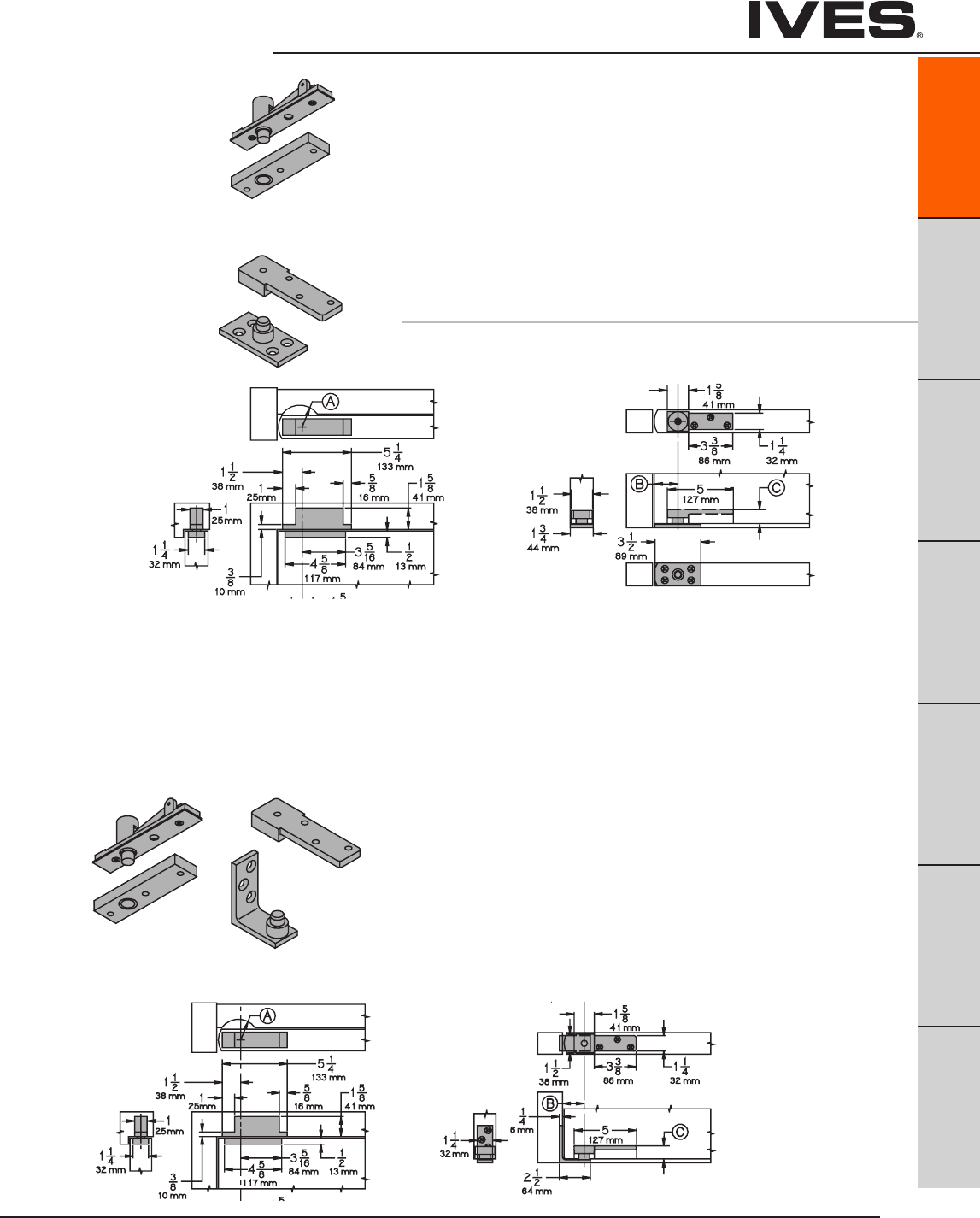
Ives Architectural hardware products
7255J Pivot Set
7255J Pivot Set
7255J Pivot Set
7255J Pivot Set
7255 Pivot Set
7255 Pivot Set
7255 Pivot Set
7255 Center Hung Pivot
• Non-Handed
• Top,headermount
• Bottom,baseplatemount
• Easyinstallationtiltonbearingandbearingpin.
• Usewith1-3/4"minimumdoorthickness.
• Adjustablefloortodoorclearance3/16"to3/4",consultant
factory if greater than 3/4"..
• Maximumdoorload500pounds
• Verticaladjustmentrange3/16",withpositivelocking
7255J Center Hung Pivot
• Non-Handed
• Top,headermount
• Bottom,jambmount
• Easyinstallationtiltonbearingandbearingpin.
• Usewith1-3/4"minimumdoorthickness.
• Adjustablefloortodoorclearance3/16"to3/4",consultfactory
if greater than 3/4".
• Maximumdoorload500pounds
• Verticaladjustmentrange3/16",withpositivelocking
• RadiusStop(A)toclearheelofdooredge.
• Pivotdistance(B)1-3/4"(44mm)minimumfromjambtocenterlineofpivotpin.Radius
heel edge of door, 1-5/8" (41mm) minimum recommended.
• Clearancefrombottomedgeofdoortofloormountingsurfaceisadjustablefrom3/16"
(5mm) to 3/4" (19mm) by varying the depth of the mortise (C ) in the bottom of the door,
refer to Chart D. Consult factory when clearance is over 3/4" (19mm).
Meets ANSI/BHMA A156.4 C07032
Meets ANSI/BHMA A156.4 C07042
Pivots
B
Pulls & Plates
A47
Hinges & Pivots
C
Flush Bolts & Coordinators
D
Latches, Catches & Bolts
E
Stops
F
Exterior Hardware
G
Miscellaneous Hardware
A47
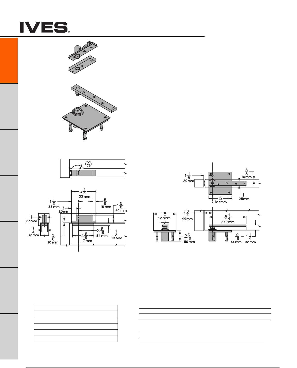
Ives Architectural hardware products
A48
Pivots
B
Pulls & Plates
A48
Hinges & Pivots
C
Flush Bolts & Coordinators
D
Latches, Catches & Bolts
E
Stops
F
Exterior Hardware
G
Miscellaneous Hardware
7256 Pivot Set
7256 Pivot Set
7256 Pivot Set
Table D
Clearance Depth of Mortise
3/16" (5mm) 1-3/16" (30mm)
3/8" (10mm) 1" (25mm)
1/2" (13mm) 7/8" (22mm)
5/8" (16mm) 3/4" (19mm)
3/4" (19mm) 5/8" (16mm)
Meets ANSI/BHMA A156.4 C07021
7256 Center Hung Pivot
• Non-Handed
• Top,headermount
• Bottom,baseframemount
• Easyinstallationtiltonbearingandbearingpin.
• Usewith1-3/4"minimumdoorthickness.
• Adjustablefloortodoorclearance3/16"to3/4",consultfactory
if greater than 3/4".
• Maximumdoorload600pounds
• Verticaladjustmentrange3/16",withpositivelocking
• RadiusStop(A)toclearheelofdooredge.
• Pivotdistance(B)1-3/4"(44mm)minimumfromjambtocenterlineofpivotpin.Radiusheel
edge of door, 1-5/8" (41mm) minimum recommended.
• Clearancefrombottomedgeofdoortofloormountingsurfaceisadjustablefrom3/16"(5mm)
to 3/4" (19mm) by varying the depth of the mortise (C ) in the bottom of the door,
refer to Chart D. Consult factory when clearance is over 3/4" (19mm).
Plated Finishes brass
US Number US3 US4 US10 US10B US26 US26D
BHMA Number 605 606 612 613 625 626
Painted Finishes brass
US Number SP4 SP10 SP28 SP313 SPBLK
BHMA Number 706 691 689 695 622
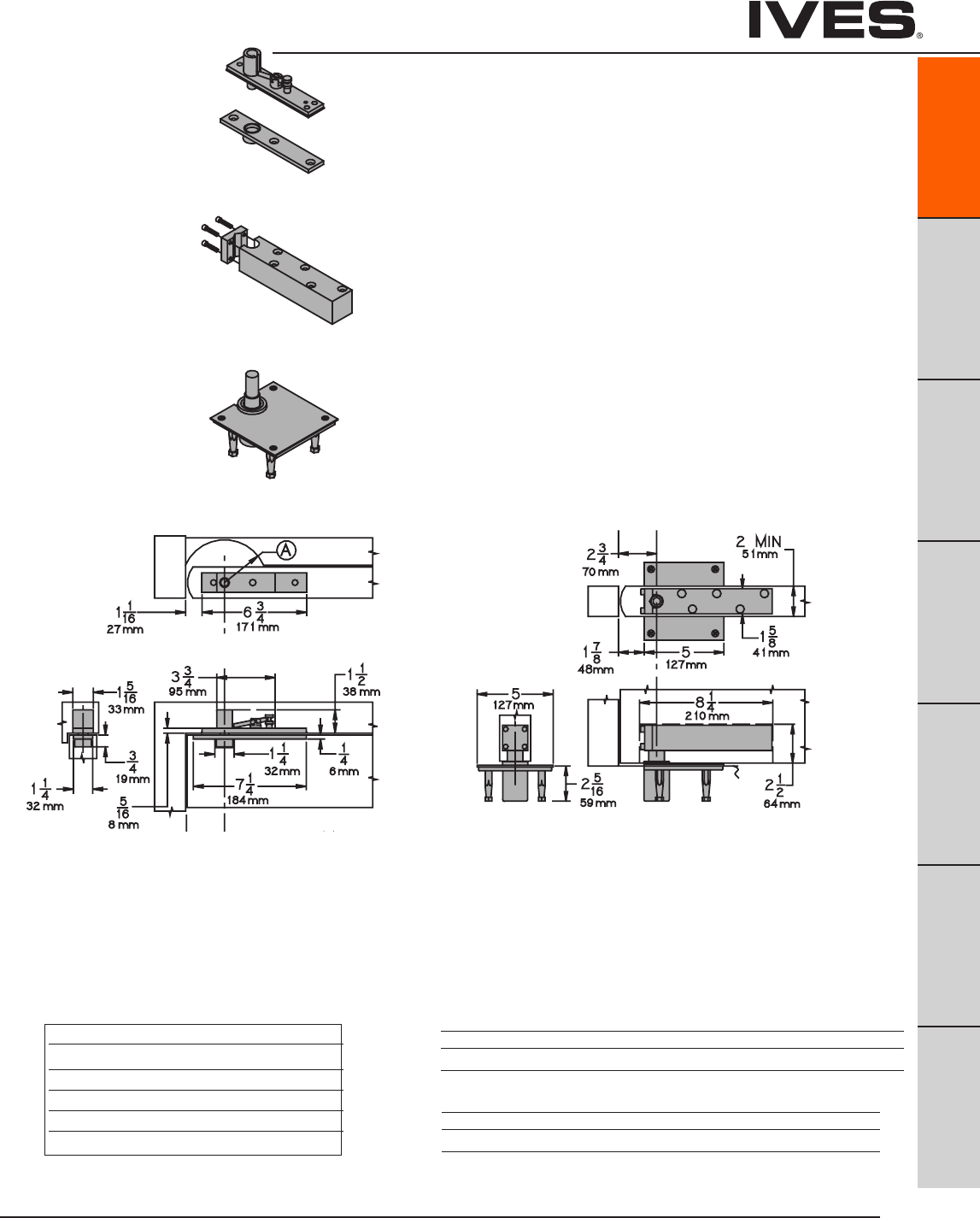
Ives Architectural hardware products
Pivots
B
Pulls & Plates
A49
Hinges & Pivots
C
Flush Bolts & Coordinators
D
Latches, Catches & Bolts
E
Stops
F
Exterior Hardware
G
Miscellaneous Hardware
A49
7259 Pivot Set
7259 Pivot Set
7259 Pivot Set
Table D
Clearance Depth of Mortise
3/16" (5mm) 1-3/16" (30mm)
3/8" (10mm) 1" (25mm)
1/2" (13mm) 7/8" (22mm)
5/8" (16mm) 3/4" (19mm)
3/4" (19mm) 5/8" (16mm)
Meets ANSI/BHMA A156.4 C07011
• RadiusStop(A)toclearheelofdooredge.
• Pivotdistance(B)1-3/4"(44mm)minimumfromjambtocenterlineofpivotpin.Radiusheel
edge of door, 1-5/8" (41mm) minimum recommended.
• Clearancefrombottomedgeofdoortofloormountingsurfaceisadjustablefrom3/16"(5mm)to
3/4" (19mm) by varying the depth of the mortise (C ) in the bottom of the door, refer to Chart D.
Consult factory when clearance is over 3/4" (19mm).
7259 Center Hung Pivot
• Non-Handed
• Top,headermount
• Bottom,baseframemount
• Easyinstallationtiltonbearingandbearingpin.
• Usewith2"minimumdoorthickness.
• Adjustablefloortodoorclearance3/16"to3/4",consultfactory
if greater than 3/4".
• Maximumdoorload1,000pounds
• Verticaladjustmentrange3/16",withpositivelocking
Plated Finishes brass
US Number US3 US4 US10 US10B US26 US26D
BHMA Number 605 606 612 613 625 626
Painted Finishes brass
US Number SP4 SP10 SP28 SP313 SPBLK
BHMA Number 706 691 689 695 622
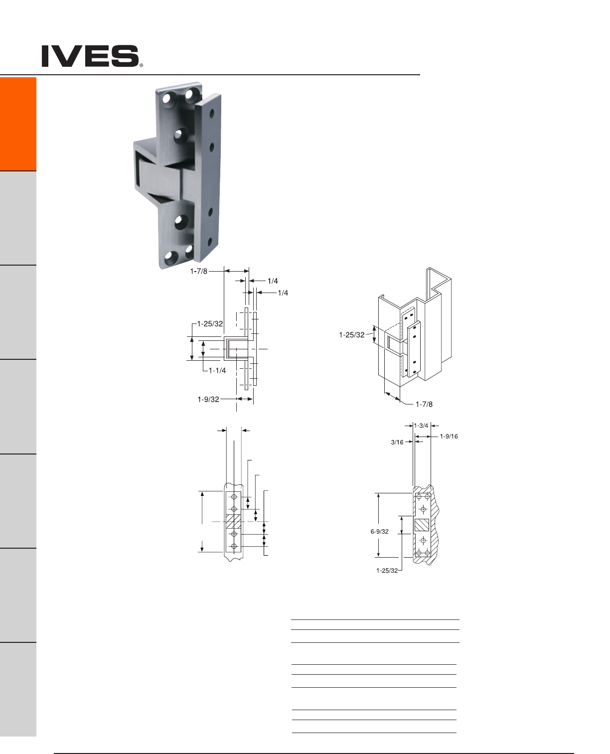
Ives Architectural hardware products
A50
Pivots
B
Pulls & Plates
A50
Hinges & Pivots
C
Flush Bolts & Coordinators
D
Latches, Catches & Bolts
E
Stops
F
Exterior Hardware
G
Miscellaneous Hardware
UL Listed 3 hour fire doors
or 20 minute wood fire doors
Meets ANSI/BHMA A156.4 C07611
91105F, 91105F-PT Pocket Pivot/Hinge
• Non-handed
• Allstainlesssteelconstruction.
• Allowsdoortoopenafull90(*degreemark)
• Fullmortise
• 90poundloadbearing
• Usetwofordoorsupto7'0"andover7'0"usethree.
• PT,PowerTransferversionhasfour28gaugewires(contactfactory
for eight wire version). Rated 50 VOC
orVAC@3.5amps.Continuousor16ampspulse.
Maximum pulse 400 milliseconds.
91105F Pocket Pivot
Pocket
Pivot
Cutout
Door Portion
1-3/8
1-1/8
1-1/8
5-17/32
1-9/64
1-9/64
C
L
of Door
Door
Portion
Jamb
Portion
Plated Finishes steel
US Number US3 US10 US10B
BHMA Number 632 639 640
Finishes stainless steel
US Number US32 US32D
BHMA Number 629 630
Painted Finishes steel
US Number USP SP313
BHMA Number 600 695
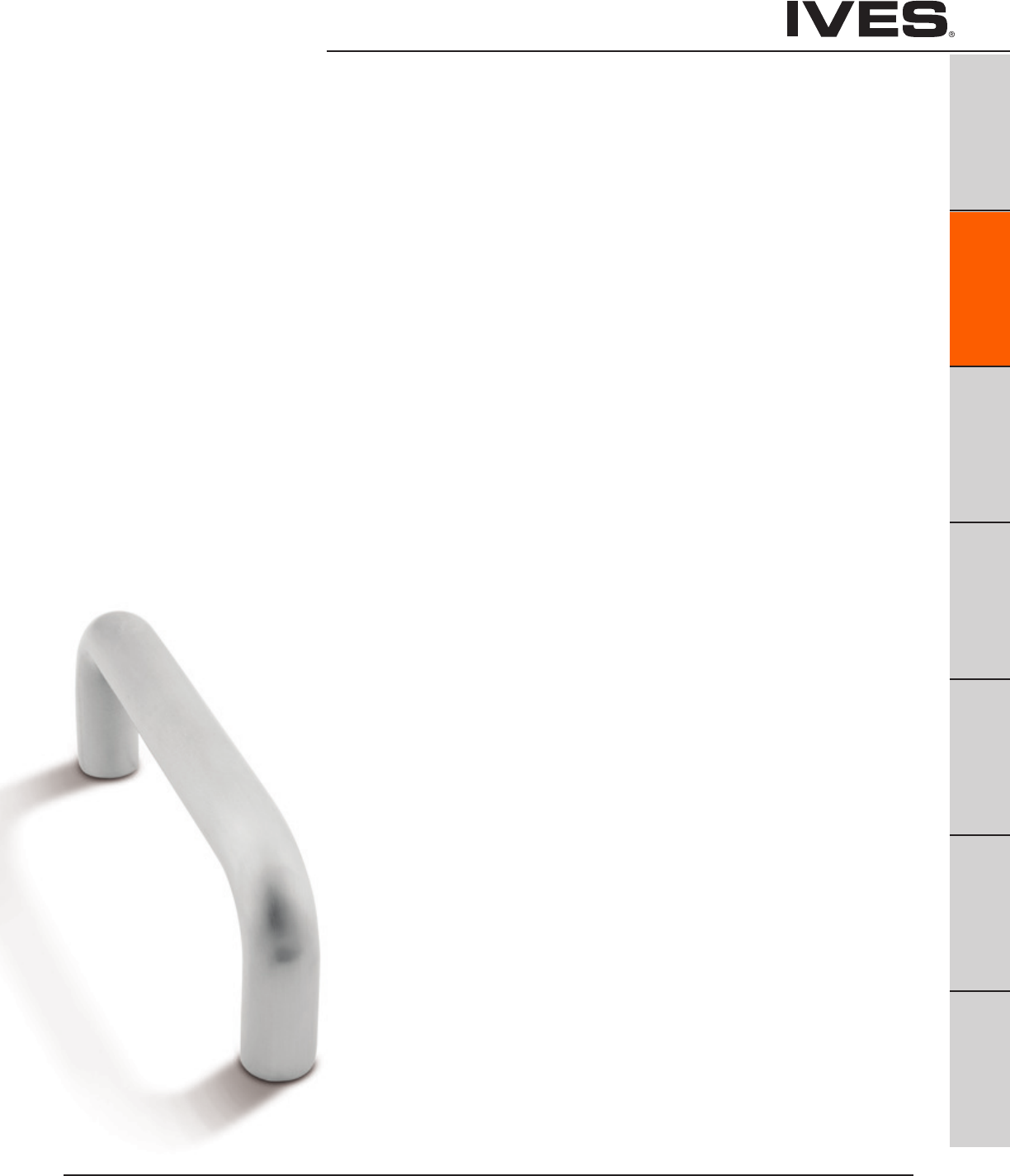
Ives Architectural hardware products B1
B1
Pulls & Plates
A
Hinges & Pivots
C
Flush Bolts & Coordinators
D
Latches, Catches & Bolts
E
Stops
F
Exterior Hardware
G
Miscellaneous Hardware
Table Of Contents
Pulls, Plates and Trim
Pulls page
8102HD Door Pull ........................................................ B2
8103HD Door Pull ........................................................ B2
8103EZHD Door Pull .....................................................B3
8105 Door Pull ........................................................... B3
8111-5 Door Pull ..........................................................B4
8112-5 Door Pull .........................................................B4
8121 Door Pull ...........................................................B5
8190HD Offset Door Pull. . . . . . . . . . . . . . . . . . . . . . . . . . . . . . . . . . . . . . . . . . . . . . . . . B5
Push and Pull Plates
8200 Push Plate ........................................................B6
8300 Pull Plate (less pull) ...............................................B6
8302 Pull Plate ..........................................................B7
8303 Pull Plate ..........................................................B7
8305 Pull Plate (with 8105) .............................................B7
8311 Pull Plate (with 8111-5) .............................................B8
Push Bars
9100HD Pushbar ........................................................B8
9103EZHD Pushber & Pull ...............................................B9
9190HD Pushbar & Pull ..................................................B9
Long Door Pulls
9264, 9266 .............................................................B10
Vandal Resistant Trim
VR810-DT, VR814DT Vandal Resistant Trim .............................B11
VR810-NL, VR814-NL Vandal Resistant Trim .............................B11
VR900, VR904 Vandual Resistant Trim ................................ B12
VR900LLP, VR904LLP Vandual Resistant Trim .........................B12
VR910-DT, VR914-DT Vandual Resistant Trim .......................... B13
VR910-NL, VR914-NL Vandual Resistant Trim .......................... B13
VR910M-DT, VR914M-DT Vandual Resistant trim ....................... B13
VR910M-NL, VR914M-NL Vandual Resistant Trim .......................B13
Protection Plates
8400 Protection Plate ...........................................B13-14, 18
8402 Protection Plate (UL) ......................................B13-14, 18
Mounting Detail
Special Mounting Detail ............................................. B15-17
Pulls & Plates
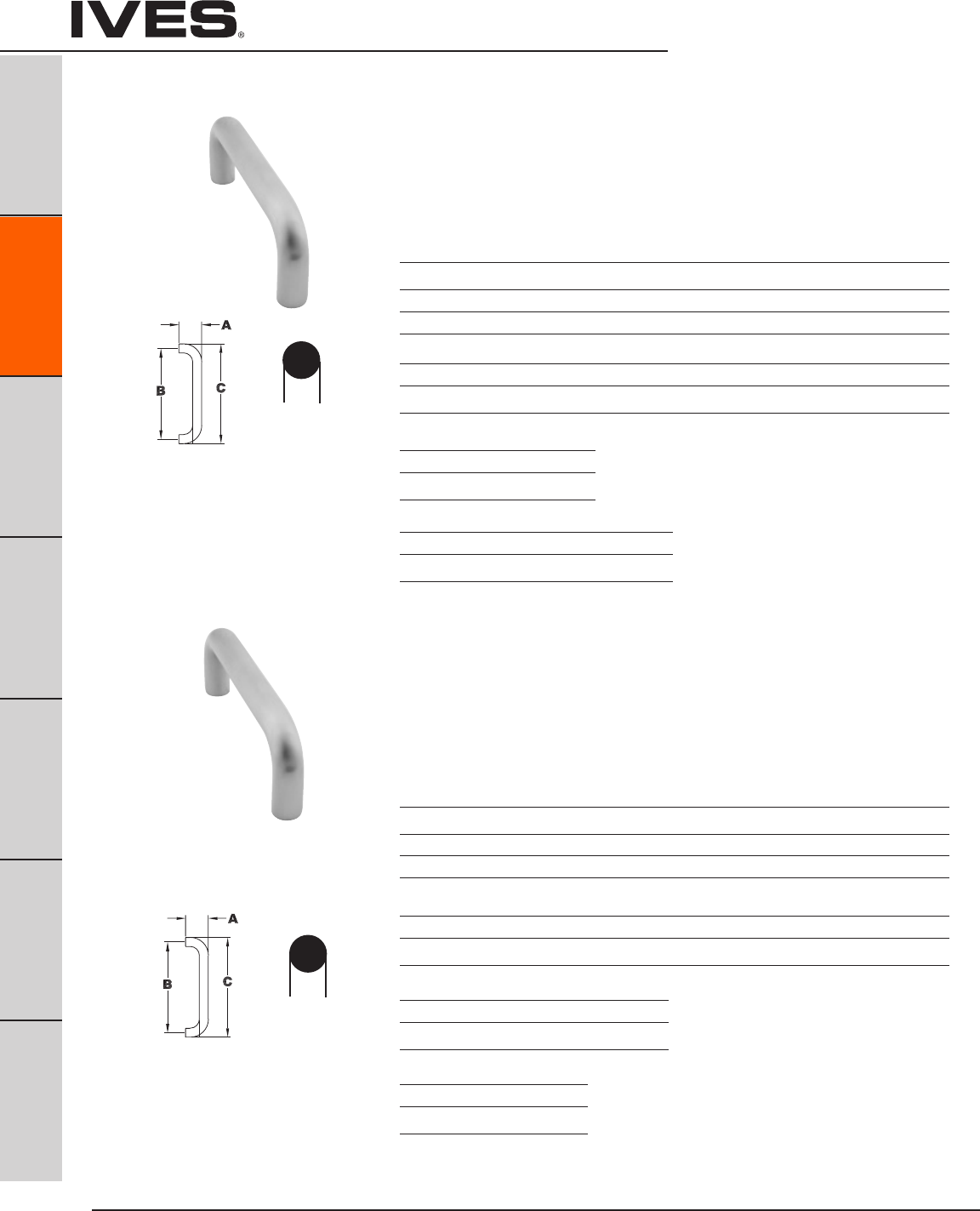
Ives Architectural hardware products
B2
Architectural Door Trim
B2
Pulls & Plates
A
Hinges & Pivots
C
Flush Bolts & Coordinators
D
Latches, Catches & Bolts
E
Stops
F
Exterior Hardware
G
Miscellaneous Hardware
Projection Center to Center Overall Length
Product No. “A” Clearance “B” “C”
8102-6 2-1/4” 1-1/2” 6” 6-3/4”
8102-8 2-1/4” 1-1/2” 8” 8-3/4”
8102-0 2-1/4” 1-1/2” 10” 10-3/4”
Available Sizes
8”, 10”, 12”
Projection Center to Center Overall Length
Product No. “A” Clearance “B” “C”
8103-8 2-1/2” 1-1/2” 8” 9”
8103-0 2-1/2” 1-1/2” 10” 11”
8103-2 2-1/2” 1-1/2” 12” 13”
Finishes brass
US Number US3 US4 US10 US10B US15 US26 US26D*
BHMA 605 606 612 613 619 625 626
Finishes stainless steel
US Number US32D*
BHMA 630
Finishes aluminum
US Number US28
BHMA 628
Finishes brass
US Number US3 US4 US10 US10B US15 US26 US26D*
BHMA 605 606 612 613 619 625 626
Finishes stainless steel
US Number US32 US32D*
BHMA 629 630
Finishes aluminum
US Number US28
BHMA 628
8102HD Door Pull - 3/4” Round
Available mounting – standard, F, H-I-L, or J see pages B15 and B16
– 5/16-18” mounting screw size
8103HD Door Pull - 1” Round
Available mounting – standard, F, H-I-L, or J see pages B15 and B16
– 3/8-16” mounting screw
Available Sizes
6”, 8”, 10”
* Available with Antimicrobial Coating, use suffix AM
* Available with Antimicrobial Coating, use suffix AM
3/4”
ROUND
1”
ROUND
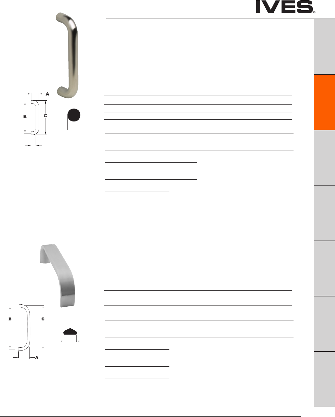
Ives Architectural hardware products B3
Architectural Door Trim
B3
Pulls & Plates
A
Hinges & Pivots
C
Flush Bolts & Coordinators
D
Latches, Catches & Bolts
E
Stops
F
Exterior Hardware
G
Miscellaneous Hardware
8103EZHD Door Pull - 1” Round
Large 2-1/2” Clearance for the Accessibility Applications
Available mounting – standard, O, H-I-L, J see pages B15 and B17
with Heavy Duty 3/8-16” mounting screws
Available Sizes
8”, 10”, 12”
Projection Center to Center Overall Length
Product No. “A” Clearance “B” “C”
8103EZ 3-1/2” 2-1/2” 8” 9”
8103EZ 3-1/2” 2-1/2” 10” 11”
8103EZ 3-1/2” 2-1/2” 12” 13”
8105 Door Pull - 1” Flattened
Available mounting – standard or F see page B15
– 1/4 - 20” mounting screws
Available Sizes
6”, 8”, 10”
Projection Center to Center Overall Length
Product No. “A” “B” “C”
8105-6 2” 6” 6-1/2”
8105-8 2” 8” 8-1/2”
8105-0 2” 10” 10-1/2”
1”
FLATTED
1/2 ROUND
Finishes brass
US Number US3 US4 US10 US10B US15 US26 US26D*
BHMA 605 606 612 613 619 625 626
Finishes stainless steel
US Number US32 US32D*
BHMA 629 630
Finishes aluminum
US Number US28
BHMA 628
Finishes brass
US Number US3 US4 US10 US10B US15 US26 US26D*
BHMA 605 606 612 613 619 625 626
Finishes stainless steel
US Number US32D*
BHMA 630
Finishes aluminum
US Number US28
BHMA 628
* Available with Antimicrobial Coating, use suffix AM
* Available with Antimicrobial Coating, use suffix AM
1”
ROUND
2-1/2”
CLEARANCE
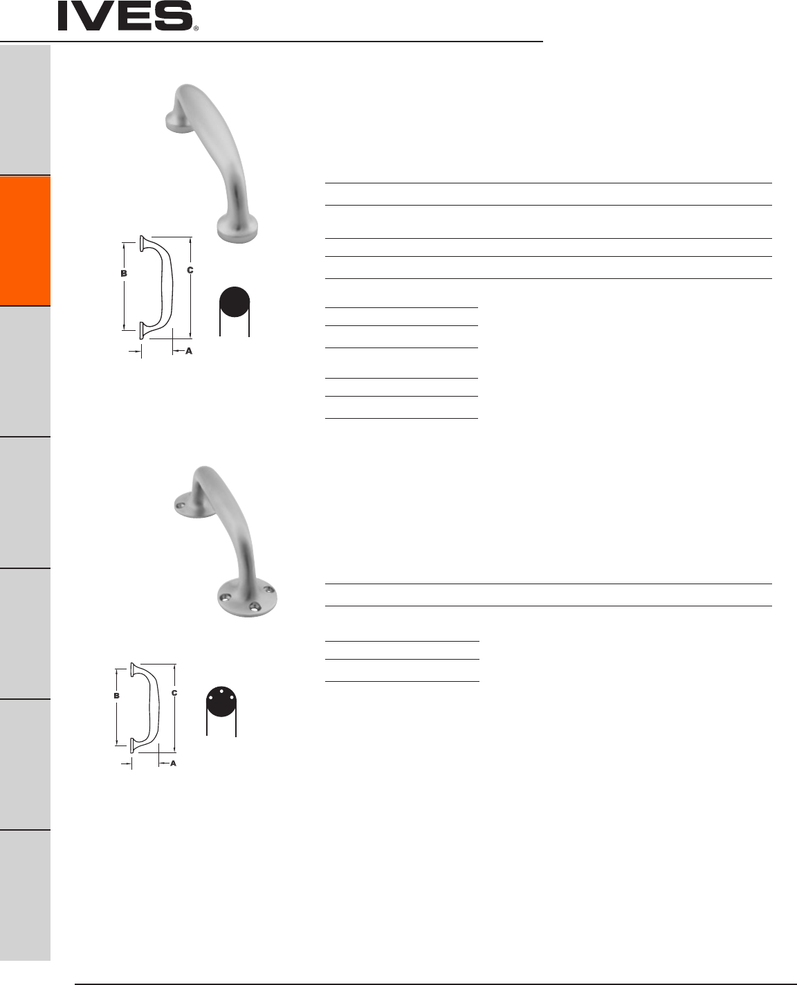
Ives Architectural hardware products
B4
Architectural Door Trim
B4
Pulls & Plates
A
Hinges & Pivots
C
Flush Bolts & Coordinators
D
Latches, Catches & Bolts
E
Stops
F
Exterior Hardware
G
Miscellaneous Hardware
8111-5 Door Pull
Available mounting – 1/4-20” mounting screws, standard see page B15
Size
5-1/4”
Projection Center to Center Overall Length
Product No. “A” “B” “C”
8111-5 1-13/16” 5-1/4” 6-1/4”
Finishes brass
US Number US3 US4 US10 US10B US15 US26 US26D*
BHMA 605 606 612 613 619 625 626
Finishes stainless steel
US Number US32D*
BHMA 630
Finishes aluminum
US Number US28
BHMA 628
8112-5 Door Pull
Standard sheet metal screws for surface mounting
Size
5-1/4”
Projection Center to Center Overall Length
Product No. “A” “B” “C”
8112-5 2-13/16” 5-5/8” 7-1/2”
Finishes brass
US Number US26D*
BHMA 626
* Available with Antimicrobial Coating, use suffix AM
* Available with Antimicrobial Coating, use suffix AM
1”
ROUND
BASE
1”
FLATTED
1/2 ROUND
1”
FLATTED
1/2 ROUND
1-7/8”
SURFACE
MOUNTED
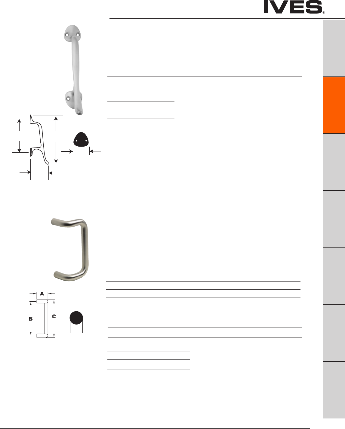
Ives Architectural hardware products B5
Architectural Door Trim
B5
Pulls & Plates
A
Hinges & Pivots
C
Flush Bolts & Coordinators
D
Latches, Catches & Bolts
E
Stops
F
Exterior Hardware
G
Miscellaneous Hardware
8121 Door Pull
Available mounting – K see page B16
Size
5-3/4”
Projection Center to Center Overall Length
Product No. “A” “B” “C”
8121-5 3-1/2” 5-3/4” 8-3/4”
C
A
1-1/2”
HOSPITAL
B
8190HD 90° Offset Door Pull
Available mounting – with heavy duty 3/8-16” mounting screws, standard H-I-L, N
or O see page B15 and B17
Available Sizes
8”, 10”, 12”, 18”
Projection Center to Center Overall Length
Product No. “A” Clearance “B” “C”
8190-8 3-1/4” 2-1/4” 8” 9”
8190-0 3-1/4” 2-1/4” 10” 11”
8190-2 3-1/4” 2-1/4” 12” 13”
8190-18 3-1/4” 2-1/4” 18” 19”
Finishes brass
US Number US3 US4 US10 US10B US15 US26 US26D*
BHMA 605 606 612 613 619 625 626
Finishes stainless steel
US Number US32 US32D*
BHMA 629 630
Finishes brass
US Number US26D*
BHMA 626
* Available with Antimicrobial Coating, use suffix AM
* Available with Antimicrobial Coating, use suffix AM
1”
ROUND
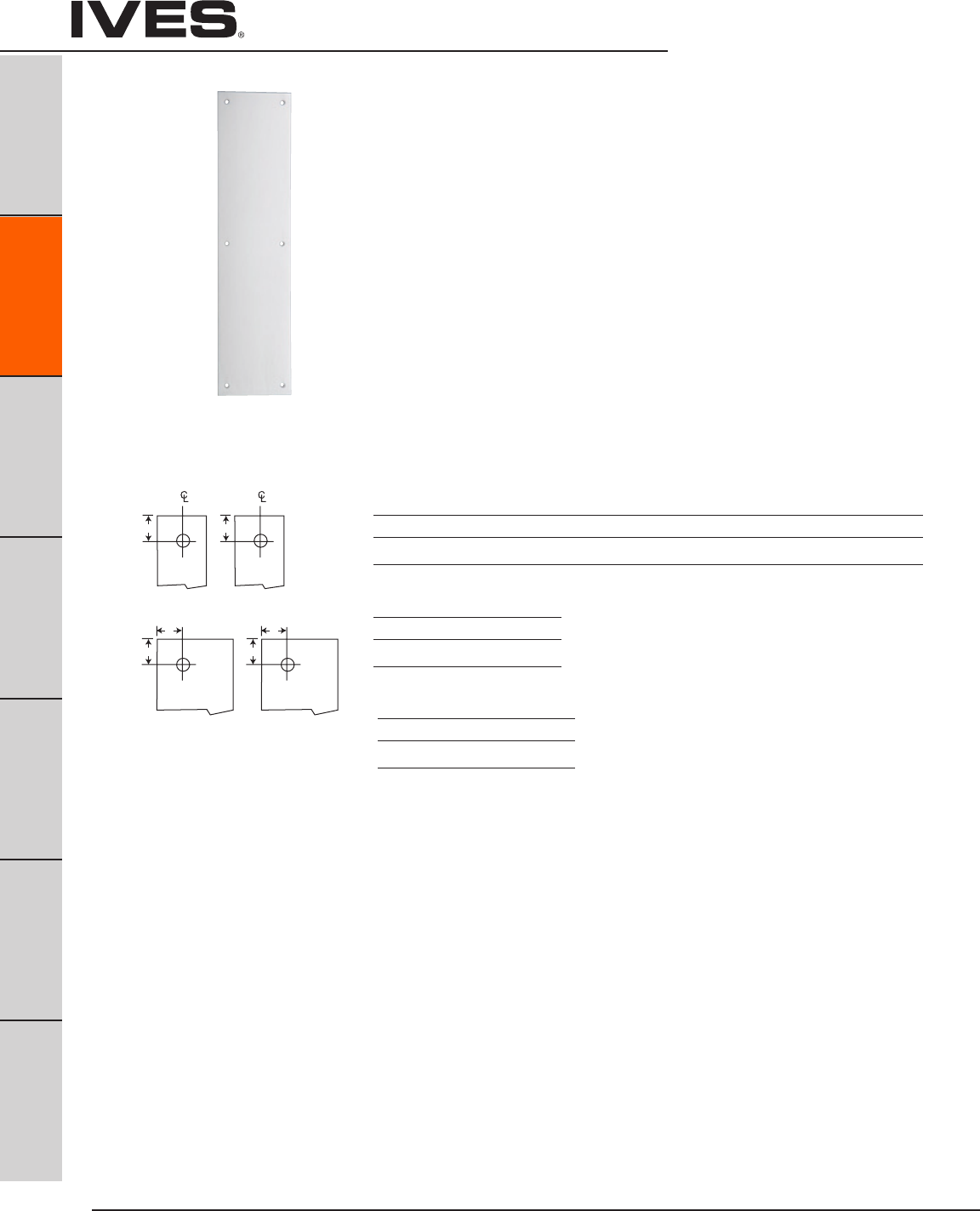
Ives Architectural hardware products
B6
Architectural Door Trim
B6
Pulls & Plates
A
Hinges & Pivots
C
Flush Bolts & Coordinators
D
Latches, Catches & Bolts
E
Stops
F
Exterior Hardware
G
Miscellaneous Hardware
Plates Cut for Cylinder or Thumbturns
Plates are available with cutout for cylinder or thumbturn; standard cutout is 2” from
top and centered on plates up to 4” wide. For plates wider than 4” cutout is located
2” from outer edge, specify LH or RH. When pull location interferes with standard
cutout location a detail drawing should be furnished with the order.
Standard cutout is 1-1/4” for cylinder and 3/8” for thumbturn.
Specify CFC for cutout for cylinder or CFT for cutout for thumbturn.
8200 Push Plate
8300 Pull Plate, Prep for Pull (less pull)
Available Sizes
3” x 12”
3.5” x 15”
4” x 16”
6” x 16”
8” x 16”
Special sizes are available. Consult factory.
2”
2”
2”
CFC
2”
CFT
CFC
2”
2”
CFT
Finishes brass
US Number US3 US4 US10 US10B US15 US26 US26D*
BHMA 605 606 612 613 619 625 626
Finishes stainless steel
US Number US32D*
BHMA 630
Finishes aluminum
US Number US28
BHMA 628
* Available with Antimicrobial Coating, use suffix AM
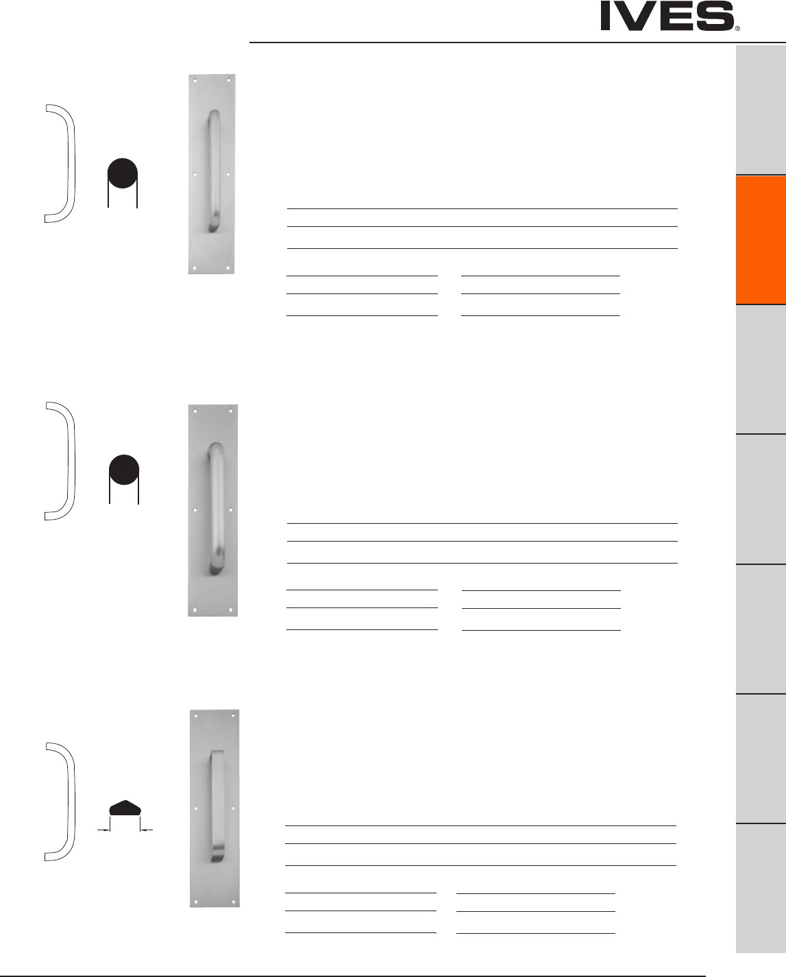
Ives Architectural hardware products B7
Architectural Door Trim
B7
Pulls & Plates
A
Hinges & Pivots
C
Flush Bolts & Coordinators
D
Latches, Catches & Bolts
E
Stops
F
Exterior Hardware
G
Miscellaneous Hardware
8302 Pull plate
Available mounting – Standard, F, G, H-I-L, or J see pages B15 and B16
Pulls have new heavy duty 5/16-18” mounting.
8300 Plate 8102 Pull
3-1/2” x 15” 6” centers
4” x 16” 8” centers
6” x 16” 10” centers
8303 Pull plate
Available mounting – Standard, F, G, H-I-L, or J see pages B15 and B16
Pulls have new heavy duty 3/8-16” mounting.
8300 Plate 8103 Pull
3-1/2” x 15” 8” centers
4” x 16” 10” centers
6” x 16” 7” centers
8305 Pull plate
Available mounting – Standard or F see page B15
Pulls have 1/4 - 20” mounting
8300 Plate 8105 Pull
3-1/2” x 15” 6” centers
4” x 16” 8” centers
6” x 16” 10” centers
Finishes brass
US Number US3 US4 US10 US10B US26 US26D*
BHMA 605 606 612 613 625 626
Finishes stainless steel
US Number US32D*
BHMA 630
Finishes aluminum
US Number US28
BHMA 628
Finishes brass
US Number US3 US4 US10 US10B US26 US26D*
BHMA 605 606 612 613 625 626
Finishes stainless steel
US Number US32D*
BHMA 630
Finishes aluminum
US Number US28
BHMA 628
Finishes brass
US Number US3 US4 US10 US10B US26 US26D
BHMA 605 606 612 613 625 626
Finishes stainless steel
US Number US32D
BHMA 630
Finishes aluminum
US Number US28
BHMA 628
* Available with Antimicrobial Coating, use suffix AM
* Available with Antimicrobial Coating, use suffix AM
* Available with Antimicrobial Coating, use suffix AM
3/4”
ROUND
1”
ROUND
1”
FLATTED
1/2 ROUND

Ives Architectural hardware products
B8
Architectural Door Trim
B8
Pulls & Plates
A
Hinges & Pivots
C
Flush Bolts & Coordinators
D
Latches, Catches & Bolts
E
Stops
F
Exterior Hardware
G
Miscellaneous Hardware
9100 Series Push Bar and Pull Combinations
• Availableinbrass,stainlesssteeloraluminum.
• Standardfastenersfurnishedfor1-3/4”thickdoors.Specifydoor
thick if other than standard.
• Speciallengthsareavailable,contactcustomerservice.
See page B17 for special mounting requirements.
Caution – the length of the pushbar should not interfere with the door jamb or
cause a pinch point.
Product No. Projection Clearance Center to Center Overall Length
9100-28 2-1/2” 1-1/2” 28” 29”
9100-33 2-1/2” 1-1/2” 33” 34”
Finishes brass
US Number US3 US4 US10 US10B US15 US26 US26D*
BHMA 605 606 612 613 619 625 626
Finishes stainless steel
US Number US32 US32D*
BHMA 629 630
9100HD Push Bar
Available mounting – NO or NS see page B17
with heavy duty 3/8-16” mounting
8311 Pull plate
Available mounting – Standard or F see page B15
Pulls have 1/4-20” mounting.
8300 Plate 8111-5 Pull
3-1/2” x 15” 5-1/8” centers
4” x 16”
6” x 16”
Finishes brass
US Number US3 US4 US10 US10B US26 US26D*
BHMA 605 606 612 613 625 626
Finishes stainless steel
US Number US32D*
BHMA 630
Finishes aluminum
US Number US28
BHMA 628
* Available with Antimicrobial Coating, use suffix AM
* Available with Antimicrobial Coating, use suffix AM
Special lengths available, consult factory
1”
ROUND
BASE
1”
ROUND
1”
FLATTED
1/2 ROUND
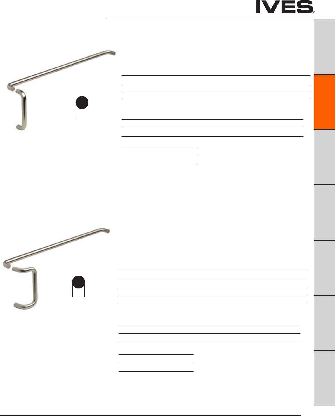
Ives Architectural hardware products B9
Architectural Door Trim
B9
Pulls & Plates
A
Hinges & Pivots
C
Flush Bolts & Coordinators
D
Latches, Catches & Bolts
E
Stops
F
Exterior Hardware
G
Miscellaneous Hardware
Finishes brass
US Number US3 US4 US10 US10B US15 US26 US26D*
BHMA 605 606 612 613 619 625 626
Finishes stainless steel
US Number US32 US32D*
BHMA 629 630
9103EZHD Straight Pull/Pushbar Combo
(8103EZHD Pull + 9100HD Push)
Available mounting – NO or NS see page B17
with heavy duty 3/8-16” mounting
Projection
Product No. CTC Push CTC Pull Push & Pull
9103EZ 28”, 33” 8” 2-1/2” & 3-1/2”
9103EZ 28”, 33” 10” 2-1/2” & 3-1/2”
9103EZ 28”, 33” 12” 2-1/2” & 3-1/2”
9190HD Offset Pull/Pushbar Combo
(8190HD pull + 9100HD push)
Available mounting – NO or NS see page B17
with heavy duty 3/8-16” mounting
Projection
Product No. CTC Push CTC Pull Push & Pull
9190 28”, 33” 8” 2-1/2” & 3-1/4”
9190 28”, 33” 10” 2-1/2” & 3-1/4”
9190 28”, 33” 12” 2-1/2” & 3-1/4”
9190 28”, 33” 18” 2-1/2” & 3-1/4”
Finishes brass
US Number US3 US4 US10 US10B US15 US26 US26D*
BHMA 605 606 612 613 619 625 626
Finishes stainless steel
US Number US32 US32D*
BHMA 629 630
* Available with Antimicrobial Coating, use suffix AM
Special lengths available, consult factory
* Available with Antimicrobial Coating, use suffix AM
Special lengths available, consult factory
1”
ROUND
1”
ROUND
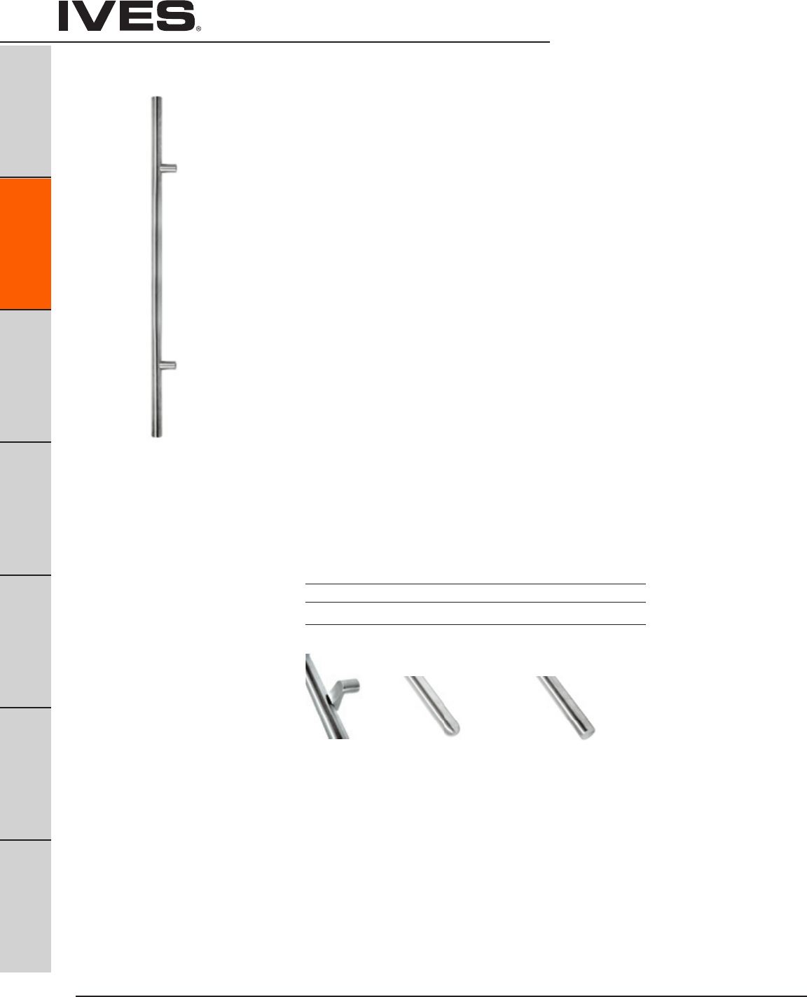
Ives Architectural hardware products
B10
B10
Pulls & Plates
A
Hinges & Pivots
C
Flush Bolts & Coordinators
D
Latches, Catches & Bolts
E
Stops
F
Exterior Hardware
G
Miscellaneous Hardware
Long Door Pulls
Long Door Pulls
Dimensions
Length: 36” / 20” CC
72” / 56” CC
Diameter: 1-1/4”
Projection: 2-3/4”
Special Lengths Available
18” and 24”
Custom lengths available from 36” to 144”
Finishes
Ives Number US3 US4 US10B US32 US32D
BHMA 605 606 613 629 630
Offset
Bracket
Note: A middle position bracket is required for pulls over 8 feet.
Flat TipRound Tip
Offered in two Models:
9264 Offset
9266 Straight
• Heavy1-1/4”RoundBrassorStainlessSteel
• RoundorFlatTip
• 316StainlessSteel
• 1-3/4˝,2˝or2-1/4˝DoorThickness
• RoundTipStandard
• FlatTipOptional
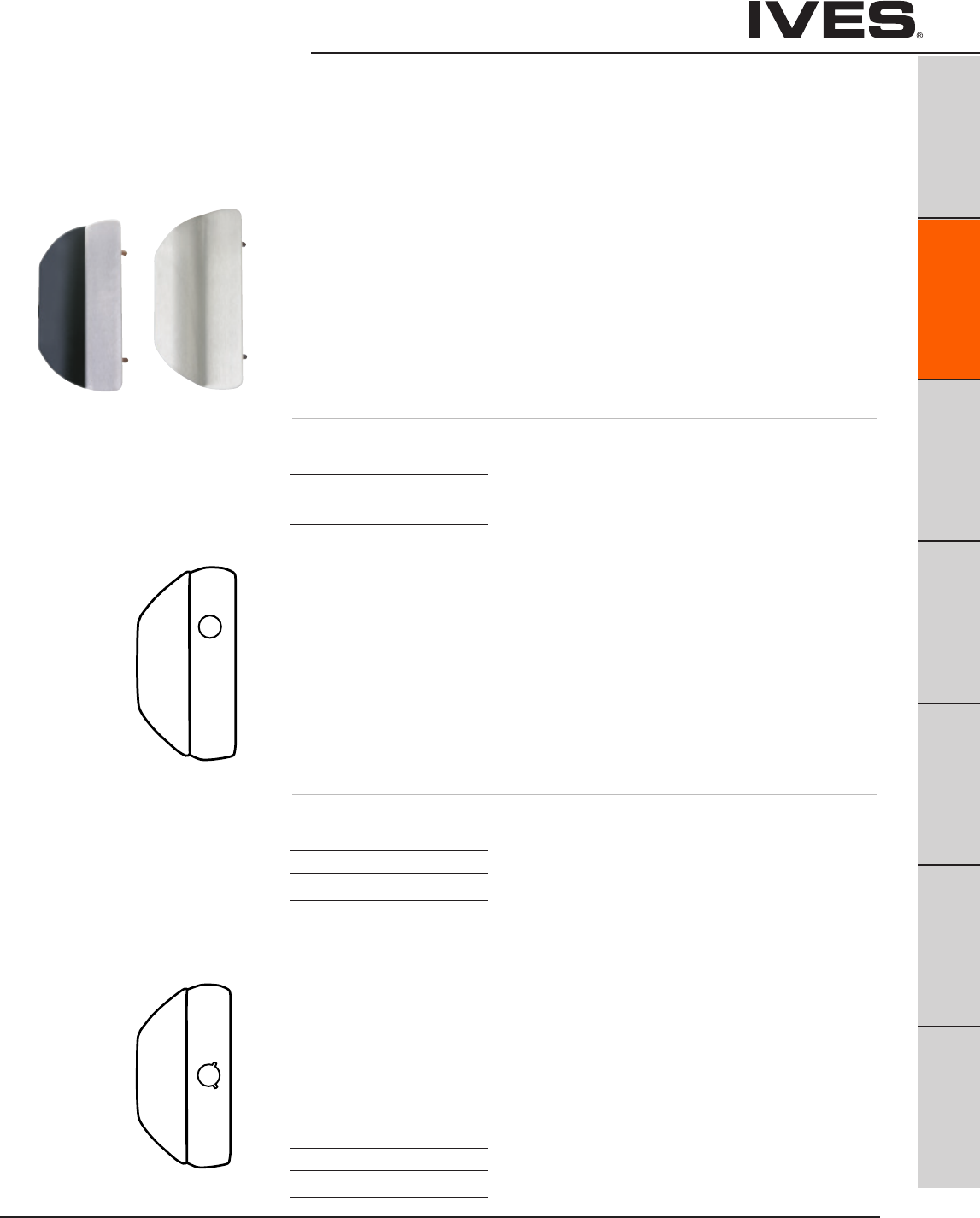
Ives Architectural hardware products B11
Vandal Resistant Trim
B11
Pulls & Plates
A
Hinges & Pivots
C
Flush Bolts & Coordinators
D
Latches, Catches & Bolts
E
Stops
F
Exterior Hardware
G
Miscellaneous Hardware
Vandal Resistant Trim
All stainless steel, 11 gauge (0.120” thick), using stainless steel fasteners for door
thickness of 1-3/4” to 2-1/4”. Built-in lock protector prevents tampering on certain
models. Protective cylinder collar spins to reduce damage from pipe wrench or other
tools. Models are available with or without attractive black plastisol edge grip.
VR810-DT With black grip
VR814-DT Without black grip
• ForusewithFalconXXor25SeriesExitDevice
• Non-handed
• Thru-boltsdirecttotheexitdevice
• Pulloperationonly
Prod. Thru-Bolt Clearance
No. Width Height Pattern Grip to Door Projection
VR810DT 5-1/4” 11” 1-3/4” wide x 7-3/4” high 1-1/2” 1-7/8”
Finishes
US Finish US32D
BHMA 630
VR810-NL LHR With black grip
VR810-NL RHR With black grip
VR814-NL LHR Without black grip
VR814-NL RHR Without black grip
• ForusewithFalconXX-V
• Thru-boltsdirecttotheexitdevice
• Nightlatchoperation(cylindernotfurnished)
VR810-NL-V With black grip
VR814-NL-V Without black grip
• ForusewithFalcon25-Ror25-VSeriesexitdevices
• Thru-boltsdirecttotheexitdevice
• Nightlatchoperation(cylindernotfurnished)
Prod. Thru-Bolt Clearance
No. Width Height Pattern Grip to Door Projection
VR810NL 5-1/4” 11” 1-3/4” wide x 7-3/4” high 1-1/2” 1-7/8”
Prod. Thru-Bolt Clearance
No. Width Height Pattern Grip to Door Projection
VR810NL-V 5-1/4” 11” 1-3/4” wide x 7-3/4” high 1-1/2” 1-7/8”
Finishes
US Finish US32D
BHMA 630
Finishes
US Finish US32D
BHMA 630
VR810 VR814

Ives Architectural hardware products
B12
Vandal Resistant Trim
B12
Pulls & Plates
A
Hinges & Pivots
C
Flush Bolts & Coordinators
D
Latches, Catches & Bolts
E
Stops
F
Exterior Hardware
G
Miscellaneous Hardware
VR900 RHR With black grip
VR900 LHR With black grip
VR904 RHR Without black grip
VR904 LHR Without black grip
• Forusewithmostmortiselocksonoutswingingdoorsincluding
• SchlageL9000SerieswithinteriorLorNescutcheon,androsetrim.
• Includesbuilt-inlockprotectorandcylindercutout.
• Handeddesignallowstrimtobepositionedtocoordinatewiththe
centerline of inside hardware.
Thru-Bolt Clearance
Width Height Pattern Grip to Door Projection
7-1/4” 11” 2” wide x 10” high 1-1/2” 1-7/8”
VR900LLP RH With black grip
VR900LLP LH With black grip
VR904LLP RH Without black grip
VR904LLP LH Without black grip
• Forusewithmostmortiselocksonoutswingingdoorsincluding
• SchlageL9000SerieswithinteriorLorNescutcheon,androsetrim.
• Includesbuilt-inlockprotectorandcylindercutout.
• Handeddesignallowstrimtobepositionedtocoordinatewiththe
centerline of inside hardware.
Thru-Bolt Clearance
Width Height Pattern Grip to Door Projection
5-1/4” 11” 1-3/4” wide x 10” high 1-1/2” 1-7/8”
Finishes
US Finish US32D
BHMA 630
Finishes
US Finish US32D
BHMA 630

Ives Architectural hardware products B13
Vandal Resistant Trim
B13
Pulls & Plates
A
Hinges & Pivots
C
Flush Bolts & Coordinators
D
Latches, Catches & Bolts
E
Stops
F
Exterior Hardware
G
Miscellaneous Hardware
VR910-DT With black grip
VR914-DT Without black grip
• ForusewithVonDuprin98/99Seriesrimandverticalrodexitdevice
• Non-handed
• Thru-boltsdirecttotheexitdevice
• Pulloperationonly.
Thru-Bolt Clearance
Width Height Pattern Grip to Door Projection
5-1/4” 11” 1-3/8” wide x 7” high 1-1/2” 1-7/8”
VR910-NL With black grip
VR914-NL Without black grip
• ForusewithVonDuprin98/99rimandverticalrodexitdevice
• Non-handed
• Thru-boltsdirecttotheexitdevice
Thru-Bolt Clearance
Width Height Pattern Grip to Door Projection
5-1/4” 11” 1-3/8” wide x 7” high 1-1/2” 1-7/8”
VR910M-DT With black grip
VR914M-DT Without black grip
• ForusewithVonDuprin9875/9975mortiselockexitdevice
• Non-handed
• Thru-boltsdirecttotheexitdevice
Thru-Bolt Clearance
Width Height Pattern Grip to Door Projection
7-1/4” 11” 1-3/8” wide x 7” high 1-1/2” 1-7/8”
VR910M-NL RHR With black grip
VR910M-NL LHR With black grip
VR914M-NL RHR Without black grip
VR914M-NL LHR Without black grip
• ForusewithVonDuprin9875/9975Seriesmortiselockexitdevice
• Thru-boltsdirecttotheexitdevice
• Nightlatchoperation(cylindernotfurnished)
Thru-Bolt Clearance
Width Height Pattern Grip to Door Projection
7-1/4” 11” 1-3/8” wide x 7” high 1-1/2” 1-7/8”
Finishes
US Finish US32D
BHMA 630
Finishes
US Finish US32D
BHMA 630
Finishes
US Finish US32D
BHMA 630
Finishes
US Finish US32D
BHMA 630
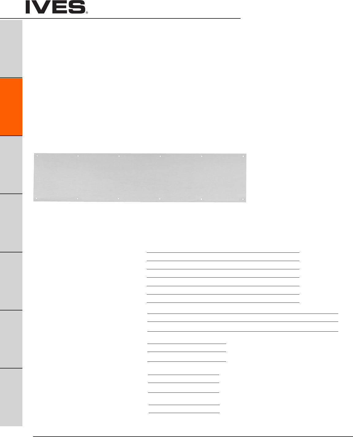
Ives Architectural hardware products
B14
Protection Plates
B14
Pulls & Plates
A
Hinges & Pivots
C
Flush Bolts & Coordinators
D
Latches, Catches & Bolts
E
Stops
F
Exterior Hardware
G
Miscellaneous Hardware
8400 Series Protection Plates
• Doorprotectionplatesareavailablein.050”thickbrass,stainless
steel or aluminum; and 1/8” thick high impact polyethylene in clear
or black.
• Beveledgeoptions;specifyB4Eforallfouredges.
• Mountingscrewpackfurnishedstandard,16screwsperpack.
Optional screw packs are available for TEK or TORK screw heads.
Refer to the following chart for ordering.
• SpecifyNMHfornomountingholes.(Notavailableon8402)
• SpecifyNMH-Afornomountingholeswithadhesive.(Notavailableon8402)
• SpecifyCSforcountersunkmountingholes.
• SpecifyERSpreppedwithextrarowofscrews.
Kickplate Gasket Tape Tape is recommended when using a
brass plate on a metal door to reduce tarnishing from electrolytic
oxidation. One tape pack will cover an the perimeters of a 8” x 34”
kickplate. Order 8401 Gasket Tape.
8400 Protection Plate
8402 (UL)* Protection Plate
*UL mark appears in upper right corner. Factory supplied screws must be used.
Number of screw packs required by plate size (specify TEK Screws or TORK screws).
22”-25” 26”-33” 34”-41” 42”-48”
4”-8” 1 1 1 1
9”-16” 1 1 1 1
17”-24” 1 1 1 2
25”-32” 1 1 2 2
33”-40” 1 2 2 2
41”-48” 2 2 2 2
Finishes brass 24” x 48” max. size
US Number US3 US4 US10 US10B US15 US26 US26D
BHMA 605 606 612 613 619 625 626
Finishes stainless steel
US Number US32 US32D
BHMA 629 630
Finishes aluminum
US Number US28
BHMA 628
Finishes plastic
Clear and Black
Residential Grade Kickplates available Carded only, finishes PA28, PA3, PA619,
PA716, B3, B505, B619, B716
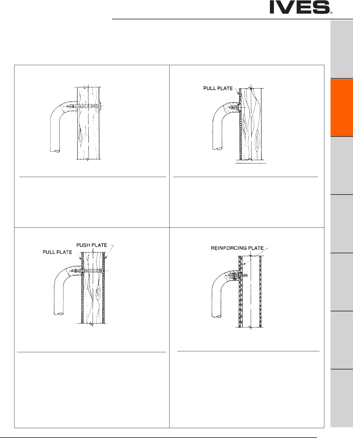
Ives Architectural hardware products B15
Push Plates
B15
Pulls & Plates
A
Hinges & Pivots
C
Flush Bolts & Coordinators
D
Latches, Catches & Bolts
E
Stops
F
Exterior Hardware
G
Miscellaneous Hardware
Mounting
Type Standard Mount Type G Mount
•Allmountinghardwareisforstandard1-3/4”door.
•ConsultCustomerServiceifotherthanstandard.
Type F Mount Type H-I-L Mount
Standard Mounting
•(2)3/8-16x2-1/4”brass,flatheadmachinescrews;
plate to match.
• (2)3/8-16countersunkwashers;platedtomatch
Note: 8102HD and 8105 have (2) 5/16-18 x 2-1/2” machine screws
-Options: (2) 5/16 countersunk washers
Wood Doors
Concealed Pull Mounting With Push Plate
• (2)2-1/4”steelflatheadmachinescrews;zincplated.
Available only for 8102HD, 8103HD, 8105, 8111, 8302, 8303, 8305 and
8311. Plate on opposite side of door must be ordered separately.
Note: 8102HD, 8302 will have 5/16-18
8105, 8111, 8305, 8311 will have 1/4-20
8103HD, 8303 will have 3/8-16”
Concealed Pull Plate Mounting
Available only for 8302, 8303, 8311 Pull Plates.
•(2)3/8-16x5/8”steelflatheadmachinescrews;zincplated.
Pull mounts directly onto plate.
Plate is attached to door by 6 screws.
Note: 8302 has (2) 5/16-19 x 5/8” steel flathead zinc plated screws
Reinforced Hollow Metal Door
Concealed Pull Mounting
Available only for 8102, 8103, 810EZ or wood door pulls, 8302,
8303 pull plates and 9264, 9265, 9266 and 9267 long door pulls.
• (2)Steelscrewsleeves;zincplated.
• (2)Steelcountersunktrimheadmachinescrew;zincplatedfor
reinforced metal door.
• (2)Steelcountersunktrimheadsteelmetalscrew;zincplated
for wood doors.
Note: 8102HD and 8302 will have 5/16-18”
8103HD, 8103EZHD, 8303 will have 3/8-16

Ives Architectural hardware products
B16
Architectural Door Trim
B16
Pulls & Plates
A
Hinges & Pivots
C
Flush Bolts & Coordinators
D
Latches, Catches & Bolts
E
Stops
F
Exterior Hardware
G
Miscellaneous Hardware
Mounting
•Allmountinghardwareisforstandard1-3/4”door.
•ConsultCustomerServiceifotherthanstandard.
Back to Back Pull Mounting
Available only for 8121-5 Pulls.
•(4)Steelscrewsleevenuts;steelzincplated.
• (8)No.8-32x1”brassovalheadmachinescrews;platedtomatch.
Pulls furnished in pairs (PR).
Type K Mount
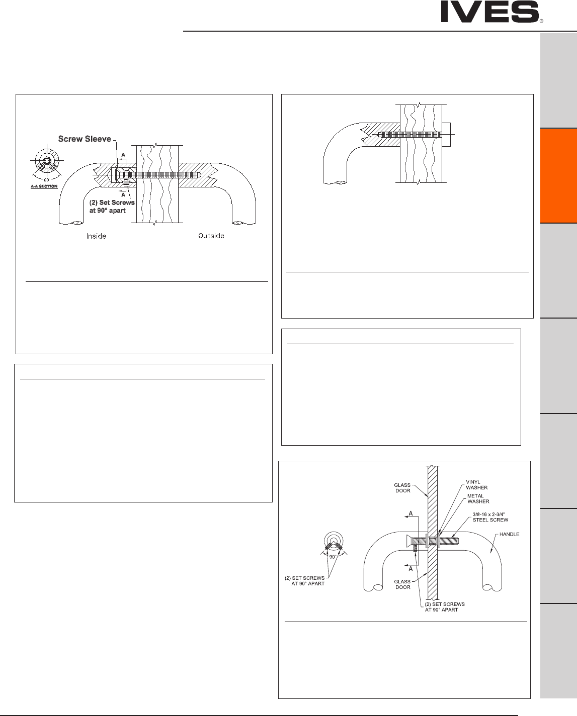
Ives Architectural hardware products B17
Architectural Door Trim
B17
Pulls & Plates
A
Hinges & Pivots
C
Flush Bolts & Coordinators
D
Latches, Catches & Bolts
E
Stops
F
Exterior Hardware
G
Miscellaneous Hardware
Type NS-Standard Push/Pull Mounting
Type N & Standard
Pushbar to Pull
- (1) 3/8 - 16 X 3”steel countersunk trim head machine screws
with (2) set screws.
- (1) steel screw sleeve, zinc plated.
Free End Pushbar & Pull
- (2) 3/8 - 16 X 2-1/4” brass, oval head mach screws;
plated to match.
- (2) No. 14 countersunk washers; plated to match.
Type NO Push/Pull Mounting
Type N & Type O
Pushbar to Pull
- (1) 3/8 -16 X 3”steel countersunk trim head machine screws
with (2) set screws.
- (1) steel screw sleeve, zinc plated.
Free End Pushbar & Pull
- (2) 3/8 - 16 X 2-1/4” blind thru-bolts; plated to match.
Mounting for 8103EZ, 8190, 9100, 9103EZ, 9190 and 9264, 9265, 9266 and
9267 long door pulls.
•Allmountinghardwareisforstandard1-3/4”door. •ConsultCustomerServiceifotherthanstandard.
Type J/N Mount Type O Mount
Type P Mount
(push) (pull)
Back to Back “Two-Anchor”
Wood or Metal Door
Available only for 8103EZHD, 8190HD, 9100HD push/pull
combinations and 9264, 9265, 9266 and 9267 long door pulls.
•(2)3/8-16x2-3/4”steelcountersunktrimheadmachinescrews
with (4) set screws for maximum anchoring force.
• (2)Steelscrewsleeves;zincplated.
Decorative Blind Thru - Bolt
Wood or Metal Door
Available only for 8103EZHD, 8190HD and 9100HD Series Push/Pull
Combinations.
•(2)3/8-16x2-1/4”blindthru-bolts;platedtomatch.
1/2” Glass Door
Available only for 8103EZHD, 8190HD, 9100HD, 9265 and 9266 long
door pulls.
•(2)3/8-16x2-1/4”steelcountersunktrimheadmachinescrews
with (4) set screws for maximum anchoring force.
• (2)Steelscrewsleeves;zincplated
•(2)MetalandVinylwashers
Ives Architectural hardware products
B18
Protection Plates
B18
Pulls & Plates
A
Hinges & Pivots
C
Flush Bolts & Coordinators
D
Latches, Catches & Bolts
E
Stops
F
Exterior Hardware
G
Miscellaneous Hardware
Mop Plates
• Protectthebottomofthepullsideofdoorsubjecttocleaning
and mopping procedures.
• SizeRanges:4”to6”high,22”to48”wide
Kick Plates
• Protectthebottomofthepushsideofdoorssubjectto
scuffing from foot traffic.
•Recommendedforalldoorssubjecttonormaluse
(especially doors using a closer).
• SizeRanges:8”to24”high,22”to48”wide
Stretcher Plates
• Protectdoorsatspecificareaswhereconsistentcontactis
made by stretchers, service carts or other equipment.
• Usuallyappliedtopushsideofdoors.
• Specify“B4E”Optionforbevelededges.
• SizeRanges:6”to8”high,22”to48”wide
Armor Plates
• Protectlowerhalfofdoorsfromabusebyhardcarts,
trucks and rough usage.
• Usuallyappliedtopushsideofsingledoorsandbothsides
of double acting doors.
• SizeRanges:26”to48”high,22”to48”wide
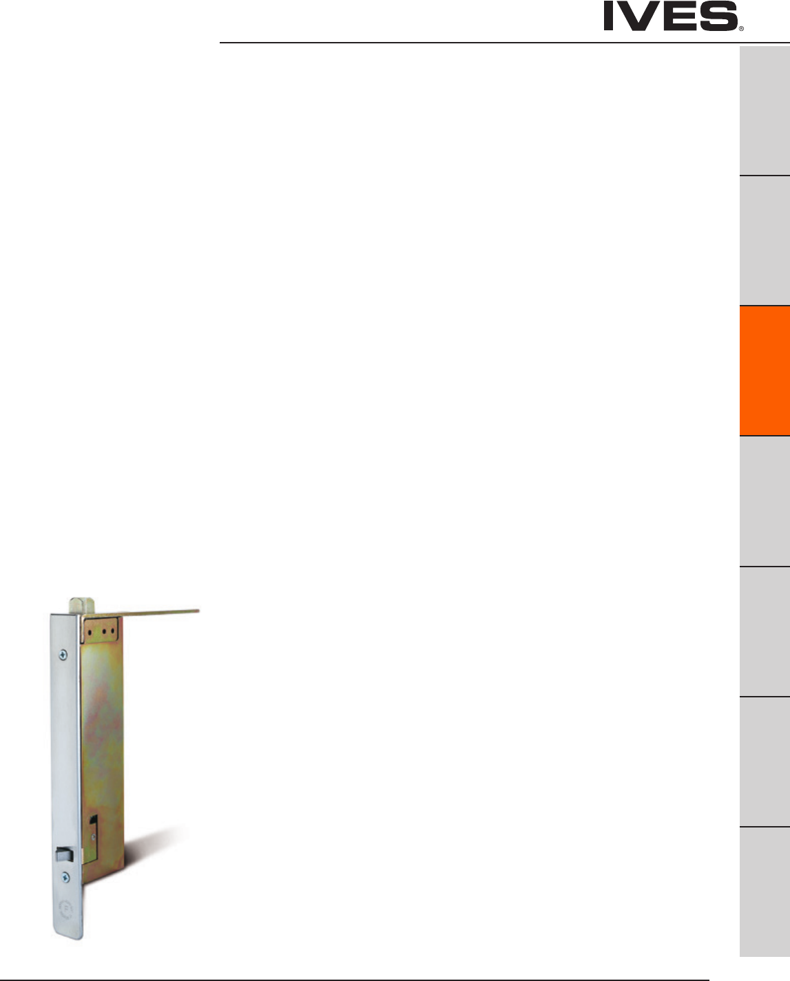
Ives Architectural hardware products C1
Flush Bolts and Coordinators
B
Pulls & Plates
A
Hinges & Pivots
C1
Flush Bolts & Coordinators
D
Latches, Catches & Bolts
E
Stops
F
Exterior Hardware
G
Miscellaneous Hardware
Table Of Contents
Flush Bolts page
FB31, FB32, FB33 Automatic Flush Bolt ................................C2
FB41, FB42 Automatic Flush Bolt ......................................C3
FB51, FB52, FB53 Automatic Flush Bolt ................................C4
FB61, FB62 Constant Latching Flush Bolt ..............................C5
261 Manual Flush Bolt .................................................C6
262 Manual Flush Bolt .................................................C6
265 Manual Flush Bolt ................................................. C7
FB358 Manual Flush Bolt ..............................................C8
FB457 Manual Flush Bolt ..............................................C9
FB458 Manual Flush Bolt ............................................. C10
DP1, DP2 Dust Proof Strike .............................................C11
Coordinators
COR Series Bar Coordinator ........................................... C12
FL Series Filler bar .................................................... C12
MB1, MB2 Mounting Brackets ......................................... C13
MB1F, MB2F, MB3F Mounting Brackets ................................ C13
MB1V, MB2V, MB3V Mounting Brackets ............................... C13
COR7G, CORG Gravity Coordinator .................................... C14
CB1 Carry Bar .........................................................C14
How to order ......................................................... C15
Special factory prep ..................................................C16

Ives Architectural hardware products
C2
Automatic Flush Bolts –
Metal Doors
B
Pulls & Plates
A
Hinges & Pivots
C2
Flush Bolts & Coordinators
D
Latches, Catches & Bolts
E
Stops
F
Exterior Hardware
G
Miscellaneous Hardware
FB31P Top and Bottom Bolts (Pair)
• FullyAutomatic—inactivedoorislatched,boltsareextendedwhen
active door closes, door is unlatched, bolts retract when active door
is opened.
• LowActuationForces—TopBoltHasNoSpringTension.
• FitsstandardANSIA115.4DoorFramePreparations.
• Non-handed.
• Boltthrowis3/4"witha7/8"verticaladjustment.
• Boltbacksetis3/4"
• StandardRodLengthis12",whichismeasuredfromthecenter
of the flush bolt body to the bolt tip. Optional rod lengths available
fortopboltonlyonnon-fireratedopenings—18",24",36"and48.
DP1 or DP2 optional dust proof strike available, see page C11.
FB31T Top Bolt Only
FB31B Bottom Bolt Only
FB32 Top Bolt with Auxiliary Fire Latch
• FB32ModelwithAuxiliaryFireLatcheliminatesthebottombolt
and is UL Listed for Fire Doors.
FB33 Top Bolt with Auxiliary Fire Latch and Retrofit Plate
• FB33ModelwithAuxiliaryFireLatcheliminatesthebottomboltand
includes a retrofit plate to cover existing bottom bolt prep.
UL Listed for Fire Doors.
Dimensions
Body Size: 1" Wide x 6-3/4" Long x 2" Deep
Guide Size: 1" Wide x 1-27/32" Long x 27/32" High x 3/32" Thick
Strike Size: 15/16" Wide x 2-1/4" Long x 1/16" Thick
Rub Plate Size: 1-1/4" Wide x 1-11/16" Long x 3/64" Thick
Auxiliary Fire Latch Size: 1" Wide x 1-3/4" Long x 3-1/4" Deep
Retrofit Plate Size: 1" Wide x 6-3/4" Long x 3/32" Thick
Meets ANSI A156.3 Type 25.
UL Listed 3 Hour Fire Doors 8'0" x 10'0"
Meets ANSI A156.3 Type 25.
UL Listed 3 Hour Fire Doors 8'0" x 8'0"
Finishes
Ives Number US3 US4 US10 US10B US32 US32D
BHMA 605 606 612 613 629 630
Top
Bolt
Top
Bolt
Auxiliary
Fire Latch
Bottom
Bolt
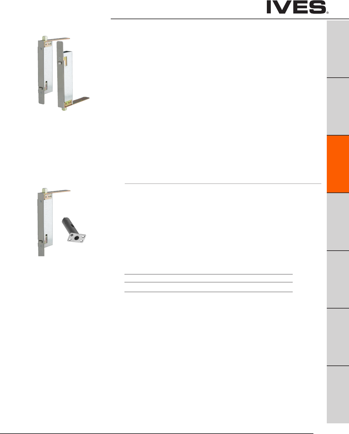
Ives Architectural hardware products C3
Automatic Flush Bolts –
Wood Doors
B
Pulls & Plates
A
Hinges & Pivots
C3
Flush Bolts & Coordinators
D
Latches, Catches & Bolts
E
Stops
F
Exterior Hardware
G
Miscellaneous Hardware
FB41P Top and Bottom Bolts (Pair)
• FullyAutomatic—inactivedoorislatched,boltsareextendedwhen
active door closes, door is unlatched bolts retract when active door
is opened.
• LowActuationForces—TopBoltHasNoSpringTension.
• Non-handed.
• Boltthrowis3/4"witha7/8"verticaladjustment.
• Boltbacksetis3/4"
DP1 or DP2 optional dust proof strike available, see page C11.
FB41T Top Bolt Only
FB41B Bottom Bolt Only
FB42 Top Bolt with Auxiliary Fire Latch
• FB42ModelwithAuxiliaryFireLatcheliminatesthebottombolt
and is UL Listed for Fire Doors.
Dimensions
Body Size: 1" Wide x 8-1/2" Long x 2" Deep
Guide Size: 1" Wide x 6" Long x 1/8" Thick
Strike Size: 15/16" Wide x 2-1/4" Long x 1/16" Thick
Rub Plate Size: 1-1/4" Wide x 1-11/16" Long x 3/64" Thick
Auxiliary Fire Latch Size: 1" Wide x 1-3/4" Long x 3-1/4" Deep
Meets ANSI A156.3 Type 25.
UL Listed 90 Minute Fire Doors 8'0" x 8'0"
Finishes
Ives Number US3 US4 US10 US10B US32 US32D
BHMA 605 606 612 613 629 630
Top
Bolt
Meets ANSI A156.3 Type 25.
UL Listed 20 Minute Fire Doors 8'0" x 8'0"
Top
Bolt
Bottom
Bolt
Auxiliary
Fire Latch
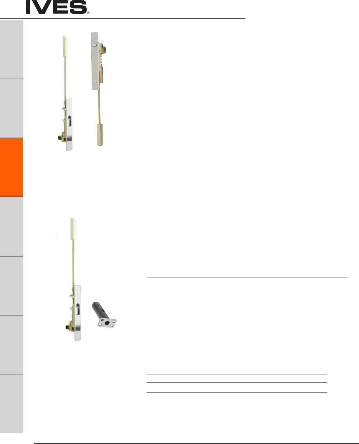
Ives Architectural hardware products
C4
Constant Latching Flush Bolts –
Metal Doors
B
Pulls & Plates
A
Hinges & Pivots
C4
Flush Bolts & Coordinators
D
Latches, Catches & Bolts
E
Stops
F
Exterior Hardware
G
Miscellaneous Hardware
FB51P Top and Bottom Bolts (Pair)
• ConstantLatching—inactivedoorremainslatcheduntil
the active door is opened, releasing the automatic bottom
bolt and then the top bolt can be manually released.
Inactive door will relatch automatically when closed.
• LowActuationForces.
• FitsstandardANSIA115.4DoorandFramePreparations.
• Non-handed.
• 3/4"boltthrowwitha7/8"verticaladjustment.
• 3/4"backset
• StandardRodLengthis12",whichismeasuredfromthecenter
of the flush bolt body to the bolt tip. Optional rod lengths available
fortopboltonlyonnon-fireratedopenings—18",24",36"and48".
DP1 or DP2 optional dust proof strike available, see page C11.
FB51T Top Bolt Only
FB52 Top Bolt with Auxiliary Fire Latch
• FB52ModelwithAuxiliaryFireLatcheliminatesthebottombolt
and is UL Listed for Fire Doors.
FB53 Top Bolt with Auxiliary Fire Latch & Retrofit Plate
• FB53ModelwithAuxiliaryFireLatcheliminatesthebottombolt
and includes a retrofit plate to cover existing bottom bolt prep.
UL Listed for Fire Doors.
Dimensions
Body Size: 1" Wide x 6-3/4" Long x 2" Deep
Guide Size: 1" Wide x 1-27/32" Long x 11/16" High x 3/32" Thick
Strike Size: 15/16" Wide x 2-1/4" Long x 1/16" Thick
Rub Plate Size: 1-1/4" Wide x 1-11/16" Long x 3/64" Thick
AuxiliaryFireLatchSize:1"Widex1-3⁄4"Longx3-1/4"Deep
Retrofit Plate Size: 1" Wide x 6-3/4" Long x 3/32" Thick
Meets ANSI A156.3 Type 27.
UL Listed 3 Hour Fire Doors 8'0" x 10'0"
Finishes
Ives Number US3 US4 US10 US10B US32 US32D
BHMA 605 606 612 613 629 630
Meets ANSI A156.3 Type 27.
UL Listed 3 Hour Fire Doors 8'0" x 10'0"
Top
Bolt
Auxiliary
Fire Latch
Top
Bolt
Bottom
Bolt

Ives Architectural hardware products C5
Constant Latching Flush Bolts –
Wood Doors
B
Pulls & Plates
A
Hinges & Pivots
C5
Flush Bolts & Coordinators
D
Latches, Catches & Bolts
E
Stops
F
Exterior Hardware
G
Miscellaneous Hardware
FB61P Top and Bottom Bolts (Pair)
• ConstantLatching—inactivedoorremainslatcheduntilthe
active door is opened, releasing the automatic bottom bolt and
then the top bolt can be manually released. Inactive door will
relatch automatically when door closes.
• LowActuationForces.
• Non-handed.
• Boltthrowis3/4"witha7/8"verticaladjustment.
• Boltbacksetis3/4"
DP1 or DP2 optional dust proof strike available, see page C11.
FB61T Top Bolt Only
FB62 Top Bolt with Auxiliary Fire Latch
• FB62ModelwithAuxiliaryFireLatcheliminatesthebottombolt
and is UL Listed for Fire Doors..
Dimensions
Body Size: 1" Wide x 8-1/2" Long x 2" Deep
Guide Size: 1" Wide x 6" Long x 1/8" Thick
Strike Size: 15/16" Wide x 2-1/4" Long x 1/16" Thick
Rub Plate Size: 1-1/4" Wide x 1-11/16" Long x 3/64" Thick
Auxiliary Fire Latch Size: 1" Wide x 1-3/4" Long x 3-1/4" Deep
Finishes
Ives Number US3 US4 US10 US10B US32 US32D
BHMA 605 606 612 613 629 630
Meets ANSI A156.3 Type 27.
UL Listed 90 Minute Fire Doors 8'0" x 8'0"
Auxiliary
Fire Latch
Top
Bolt
Bottom
Bolt
Meets ANSI A156.3 Type 27.
UL Listed 20 Minute Fire Doors 8'0" x 8'0"
Top
Bolt
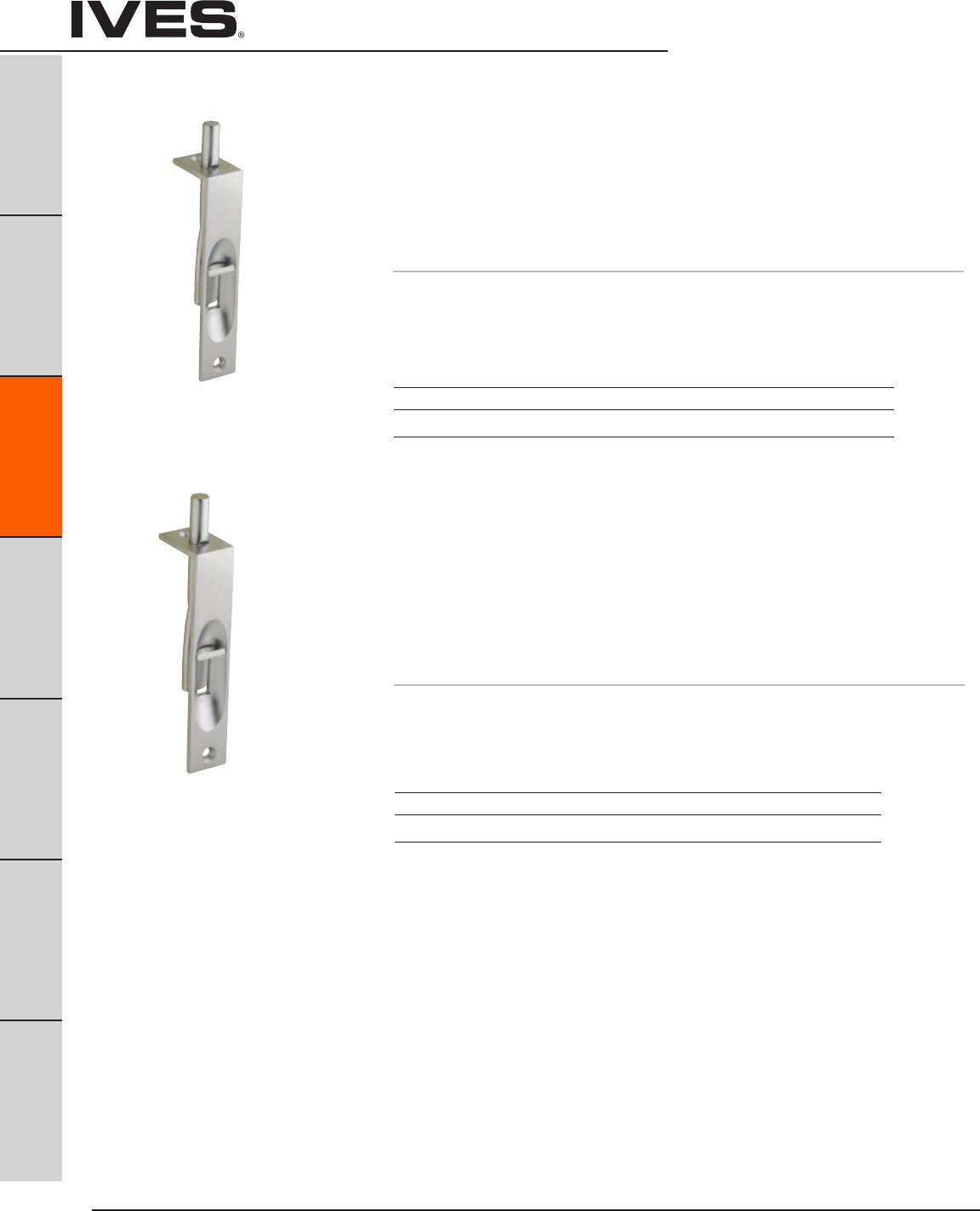
Ives Architectural hardware products
C6
Manual Flush Bolts
B
Pulls & Plates
A
Hinges & Pivots
C6
Flush Bolts & Coordinators
D
Latches, Catches & Bolts
E
Stops
F
Exterior Hardware
G
Miscellaneous Hardware
262 Flush Bolt
• Anexceptionallysmoothworkingflushboltwithsharp,crisplines.
• Doubleactionspringdesignprovidesautomaticholdingofbrass
bolt in projected or retracted position, and assures ease of
operation in conjunction with deep cup finger hole.
• Madefrompolishedcastbrass.
• Bolttipis1/2"Diameter
• Boltthrowis1"
• Boltbacksetis15/32"
Dimensions
Body Size: 3/4" W x 6" L x 1-11/32" D
Strike Size: 7/8" W x 1-3/4" L
Meets ANSI/BHMA A156.16, L04201.
Meets ANSI/BHMA A156.16, L04201.
Finishes
Ives Number B3 B5 B10B B15 B26 B26D
BHMA 605 609 613 619 625 626
Finishes
Ives Number B3 B5 B10B B15 B26 B26D
BHMA 605 609 613 619 625 626
261 Flush Bolt
• Anexceptionallysmoothworkingflushboltwithsharp,crisplines.
• Doubleactionspringdesignprovidesautomaticholdingofbrass
bolt in projected or retracted position, and assures ease of
operation in conjunction with deep cup finger hole.
• Madefrompolishedcastbrass.
• Bolttipis5/16"Diameter
• Boltthrowis3/4"
• Boltbacksetis15/32"
Dimensions
Body Size: 3/4" Wide x 4" Long x 1-1/8" Deep
Strike Size: 5/8" Wide x 1-1/2" Long
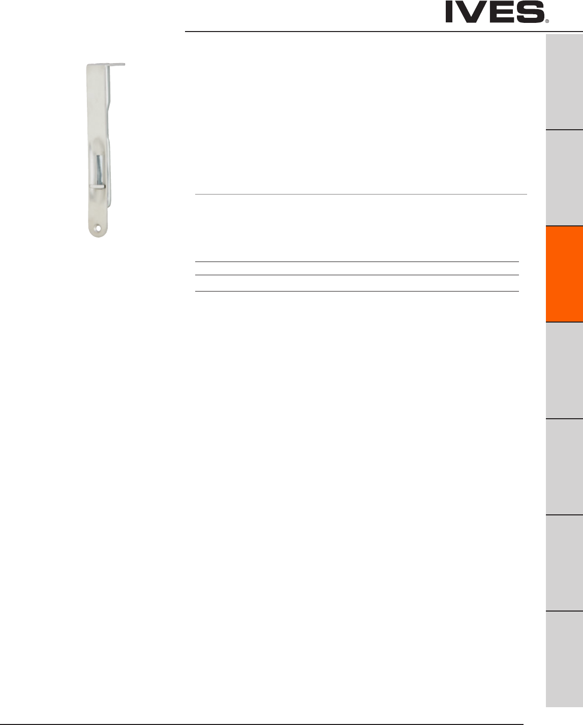
Ives Architectural hardware products C7
Manual Flush Bolts
B
Pulls & Plates
A
Hinges & Pivots
C7
Flush Bolts & Coordinators
D
Latches, Catches & Bolts
E
Stops
F
Exterior Hardware
G
Miscellaneous Hardware
265 Flush Bolt
• Aflushboltwithradiusedbottomfaceplatedesignedspecifically
for simple one-step router installation.
• Doubleactionspringdesignprovidesautomaticholdingofbrass
bolt in projected or retracted position, and assures ease of
operation in conjunction with deep cup finger hole.
• Faceplateispolishedsolidbrass;boltismadefromaluminumzincalloy.
• Bolttipis1/2"Diameter
• Boltthrowis1"
• Boltbacksetis1/2"
Dimensions
Body Size: 3/4" W x 6" L x 1-7/16" D
Strike Size: 7/8" W x 1-3/4" L
Finishes
Ives Number B3 B5 B10B B15 B26 B26D
BHMA 605 609 613 619 625 626
Meets ANSI/BHMA A156.16, L04201.
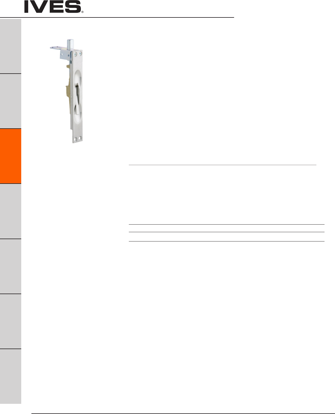
Ives Architectural hardware products
C8
Manual Flush Bolts –
Wood Doors
B
Pulls & Plates
A
Hinges & Pivots
C8
Flush Bolts & Coordinators
D
Latches, Catches & Bolts
E
Stops
F
Exterior Hardware
G
Miscellaneous Hardware
FB358 Top or Bottom Bolts
• Whentheactivedoorisopened,thelevercanbemovedtothe
‘up’ position, retracting the bolt and allowing the inactive leaf to be
opened. When the inactive leaf is closed, the lever can be moved to
the ‘down’ position, projecting the bolt into the strike and securely
locking the inactive leaf.
• Reducesinstallationcosts;requiresonlysimpleroutermortise
at top and bottom corners of doors.
• Doorstrengthandrigiditymaintainedbytyingdoorfacesto
reinforcing extensions on guide with machine screws and
bearing washers, not supplied.
• Non-handed.
• Bolttip1/2"diameter
• Boltthrowis3/4"witha7/8"verticaladjustment.
• Boltbacksetis3/4"
• Notavailableforrabbeteddoorinstallations.
DP1 or DP2 optional dust proof strike available, see page C11.
Dimensions
Body Size: 1" Wide x 6-3/4" Long x 1-3/8" Deep
Guide Size: 1" Wide x 2-1/2" Long x 5/64" Thick
Strike Size: 15/16" Wide x 2-1/4" Long x 5/64" Thick
Meets ANSI/BHMA A156.16, L04261.
UL Listed 90 Minute Fire Doors 8'0" x 10'0"
Finishes
Ives Number US3 US4 US10 US10B US15 US26 US26D
BHMA 605 606 612 613 619 625 626
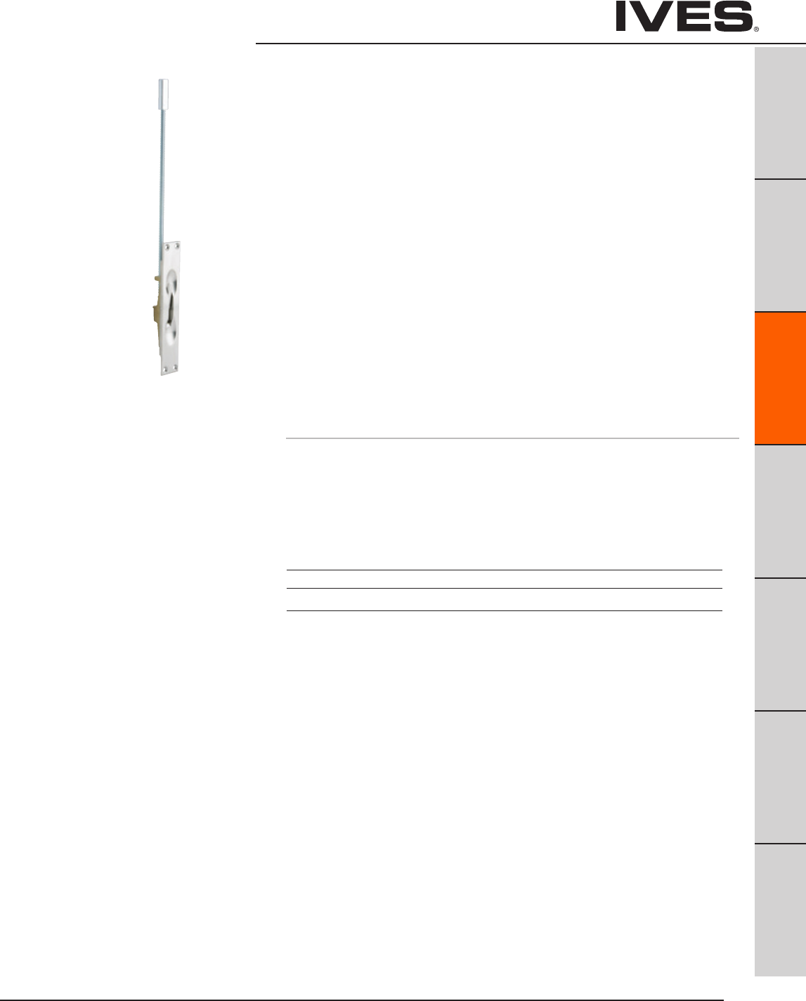
Ives Architectural hardware products C9
Manual Flush Bolts –
Metal Doors
B
Pulls & Plates
A
Hinges & Pivots
C9
Flush Bolts & Coordinators
D
Latches, Catches & Bolts
E
Stops
F
Exterior Hardware
G
Miscellaneous Hardware
FB457 Top or Bottom Bolts
• Whentheactivedoorisopened,thelevercanbemovedtothe
‘up’ position, retracting the bolt and allowing the inactive leaf to be
opened. When the inactive leaf is closed, the lever can be moved to
the ‘down’ position, projecting the bolt into the strike and securely
locking the inactive leaf.
• Simplifiedinstallationinmetalframes.Roundboltheadrequiresonly
a punched hole. Use of strike optional. Special design of guide and
flat sided bolt tip to prevent bolt rotation.
• Non-handed.
• Bolttipis1/2"Diameter.
• Boltthrowis3/4"witha7/8"verticaladjustment.
• Boltbacksetis3/4"
• StandardRodLengthis12",whichismeasuredfromthecenter
of the flush bolt body to the bolt tip. Optional rod lengths available -
6", 9", 18" and 24" for fire rated doors. Optional rod lengths available -
6", 9", 18", 24", 30", 36" and 48" for non-fire rated doors.
DP1 or DP2 optional dust proof strike available, see page C11.
Dimensions
Body Size: 1-1/4" Wide x 6-3/4" Long x 1-1/8" Deep
Guide Size: 1" Wide x 2" Long x 5/64" Thick
Strike Size: 15/16" Wide x 2-1/4" Long x 5/64" Thick
Meets ANSI/BHMA A156.16, L04251.
UL Listed 3 Hour Fire Doors 8'0" x 10'0"
Finishes
Ives Number US3 US4 US10 US10B US15 US26 US26D
BHMA 605 606 612 613 619 625 626
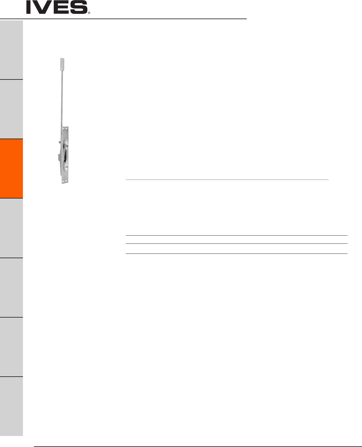
Ives Architectural hardware products
C10
Manual Flush Bolts –
Metal Doors
B
Pulls & Plates
A
Hinges & Pivots
C10
Flush Bolts & Coordinators
D
Latches, Catches & Bolts
E
Stops
F
Exterior Hardware
G
Miscellaneous Hardware
FB458 Top or Bottom Bolts
• Whentheactivedoorisopened,thelevercanbemovedtothe‘up’
position, retracting the bolt and allowing the inactive leaf to be
opened. When the inactive leaf is closed, the lever can be moved to
the ‘down’ position, projecting the bolt into the strike and securely
locking the inactive leaf.
• Simplifiedinstallationinmetalframes.Roundboltheadrequiresonly
a punched hole. Use of strike optional. Special design of guide and
flat sided bolt tip to prevent bolt rotation.
• Non-handed.
• Bolttipis1/2"diameter.
• Boltthrowis3/4"witha7/8"verticaladjustment.
• Boltbacksetis3/4"
• StandardRodLengthis12",whichismeasuredfromthecenter
of the flush bolt body to the bolt tip. Optional Rod Lengths available -
6", 9", 18" and 24" for fire rated Doors. Optional Rod lengths
available - 6", 9", 18", 24", 30", 36" and 48" for non-fire rated doors.
DP1 or DP2 optional dust proof strike available, see page C11.
Dimensions
Body Size: 1" Wide x 6-3/4" Long x 1-1/8" Deep
Guide Size: 1" Wide x 2" Long x 5/64" Thick
Strike Size: 15/16" Wide x 2-1/4" Long x 5/64" Thick
Meets ANSI/BHMA A156.16, L04251.
UL Listed 90 Minute Fire Doors 8'0" x 10'0"
Finishes
Ives Number US3 US4 US5 US10 US10B US15 US26 US26D
BHMA 605 606 609 612 613 619 625 626
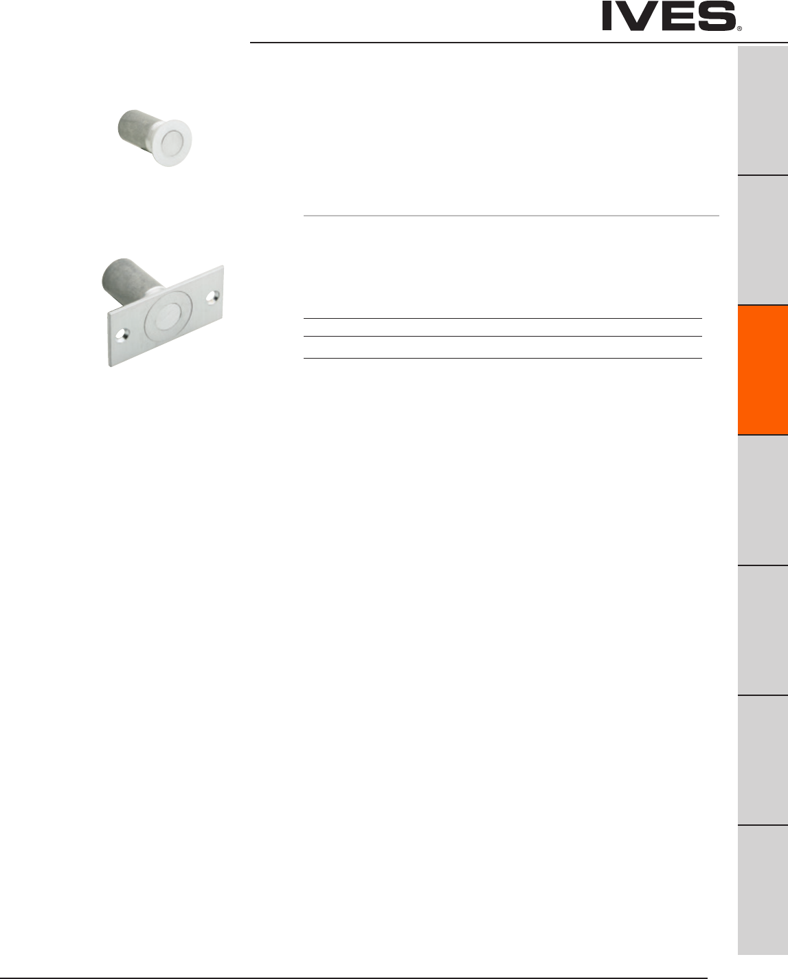
Ives Architectural hardware products C11
Dust Proof Strikes
B
Pulls & Plates
A
Hinges & Pivots
C11
Flush Bolts & Coordinators
D
Latches, Catches & Bolts
E
Stops
F
Exterior Hardware
G
Miscellaneous Hardware
DP1
DP2 Dust Proof Strikes
• Designedforusewiththebottomboltofallflushbolts.
• Spring-loadedplungerreturnstofloororthresholdlevelanytime
flush bolt is retracted, eliminating need to clean standard
floor strikes.
• Strikeholeis3/4"Diameterand1-1/8"Deep
Dimensions
DP1 Face Plate: 1-7/16" Diameter
DP2 Face Plate: 1-5/8" W x 3-1/2" L x 1/8" Thick
Body: 1-3/16" Diameter x 1-7/8" Deep
DP1
DP2
Meets Meets ANSI/BHMA 156.16, L14011.
Finishes
Ives Number US3 US4 US10 US10B US26 US26D
BHMA 605 606 612 613 625 626
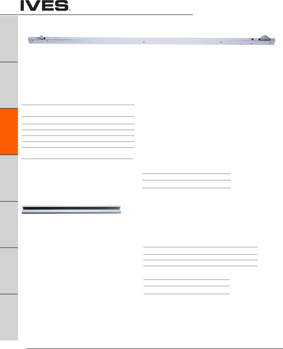
Ives Architectural hardware products
C12
Coordinators –
Bar Coordinators and Filler Bars
B
Pulls & Plates
A
Hinges & Pivots
C12
Flush Bolts & Coordinators
D
Latches, Catches & Bolts
E
Stops
F
Exterior Hardware
G
Miscellaneous Hardware
COR Series Bar Coodinators
• TheCORSeriesCoordinatorsaredesignedforuseonpairsofdoors
when one door needs to close before the other.
• AllCORunitsfunctioneasily.Theactivedoorlever,locatednearestto
the active stop, holds the active door open until the trigger
mechanism is released by the closing of the inactive leaf.
• AllCORunitsmaynotfunctioncorrectlywithswingclearhinges.
• AllCORunitsareequippedwithanadjustableoverridefeaturewhich
allows the active door to close under extreme pressure.
• AllCORunitsarecompatiblewithFlushBolts.
• TheCORSeriesisavailableinfivesizesforvariabledooropening
widths.
• TheCORSeriesdoesnotcovertheentirelengthofthestop,
so a FL filler bar can be provided to maintain architecturally clean lines.
• CORSeriesCoordinatorChannelsandFLfillersaremadeofaluminum.
• OptionalFillerBars:FL20-20",FL32-32"andFL44-44",available
to maintain clean line.
• OptionalMountingBracketsavailable:MB1,MB2,MB1F,MB2F,
MB3F, MB1V, MB2V, and MB3V for other stop applied hardware.
FL Series Filler Bars
• TheFLFillerBarsareavailableinthreesizesforvariableframe
openings.
• FLFillerBarsaremadeofaluminum
• FLFillerBarsarefieldsizedtoframeopening.
For Openings Where Doors Are Same Size
Coordinator Length of For Opening Common
Number Channel Widths Applications
COR32 32" 34" - 52" Pair of 2'0" Doors
COR42 42" 52" - 72" Pair of 2'6" Doors
COR52 52" 62" - 92" Pair of 3'0" Doors
COR60 60" 70" - 108" Pair of 3'6" Doors
COR72 72" 84" - 132" Pair of 4'0" Doors
For Openings Where Doors Are Unequal Size
The coordinator length should equal the active door width plus
approximately 1/2 the inactive door width. The coordinator must
be 6" longer than the active door width and shorter than the overall
frame opening between stops.
Filler Bar
Number Length Dimensions
FL20 20" 1-5/8" W x 5/8" D x 20" L
FL32 32" 1-5/8" W x 5/8" D x 32" L
FL44 44" 1-5/8" W x 5/8" D x 44" L
Meets ANSI/BHMA A156.3, Type 21A.
UL Listed for installation on labeled frame.
Finishes
Ives Finish US28 US26D 315AN
BHMA 628 713 711
Finishes
Ives Finish US28 US26D 315AN
BHMA 628 713 711
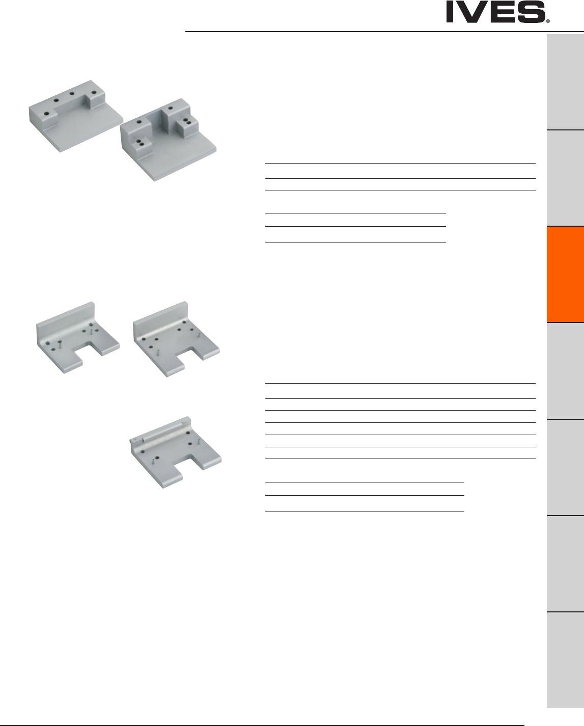
Ives Architectural hardware products C13
Coordinators –
Mounting Brackets
B
Pulls & Plates
A
Hinges & Pivots
C13
Flush Bolts & Coordinators
D
Latches, Catches & Bolts
E
Stops
F
Exterior Hardware
G
Miscellaneous Hardware
MB1and MB2 Mounting Brackets
• Allowsstopmountedhardwaretobeproperlyinstalledwithout
damaging the COR coordinator, such as a parallel arm closer or
a non-fire-rated surface vertical rod strike.
• Stopmountedhardwarewillneedtobeloweredtocompensate
for the height of the coordinator and mounting bracket.
• MBmountingbracketsaremadeofaluminum
MB1F, MB2F and MB3F Fire Rated Mounting Brackets
MB1V, MB2V and MB3V • Allowsforfire-ratedstopmountedhardwaretobeproperlyinstalled
without damaging the COR Coordinators, such as fire-rated surface
vertical rod exit device strikes.
• Latchwillneedtobeloweredtocompensatefortheheightofthe
coordinator and mounting bracket.
• MB-VaredesignedforVonDuprin8827-Fsoffitlatch.
• Mountingbracketsaremadeofsteel.
Product Jamb Depth Stop Width Dimensions
MB1 4-3/4" Min. Over 2-1/2" 4" W x 3" D x 15/16" T
MB2 4-3/4" Min. Up to 2-1/2" 4" W x 3-1/4" D x 1-5/8" T
Product Jamb Depth Stop Width Dimensions
MB1F 5" 1-1/2" - 2-1/4" 4" W x 3" D x 1-5/8" T
MB1V 5" 1-1/2" - 2-1/4" 4" W x 3" D x 1-5/8" T
MB2F 5-7/8" 2-3/8" - 3-1/4" 4"W x 4" D x 1-5/8"T
MB2V 5-7/8" 2-3/8" - 3-1/4" 4"W x 4" D x 1-5/8"T
MB3F 6-7/8" Over 3-3/8" 4"W x 3-1/2" D x 1"T
MB3V 6-7/8" Over 3-3/8" 4"W x 3-1/2" D x 1"T
Finishes
Ives Finish USP SP28 SPBLK
BHMA 600 689 622
Finishes
Ives Finish USP SP28 SPBLK
BHMA 600 689 622
MB1V MB2V
MB3V
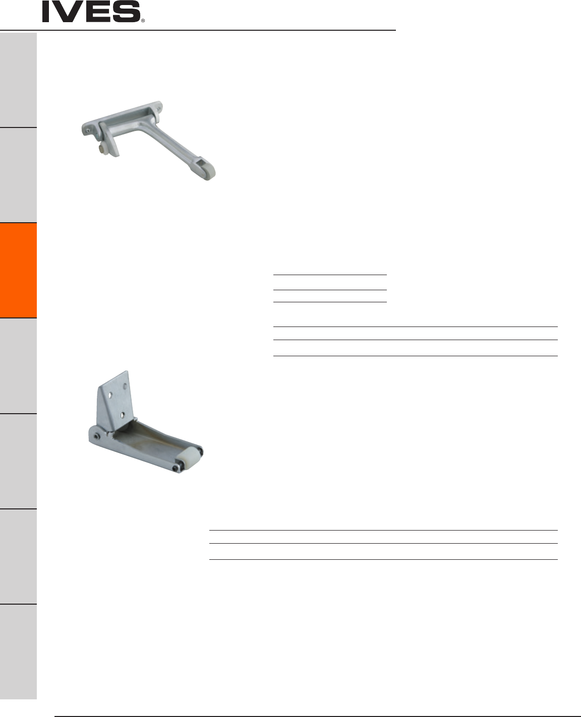
Ives Architectural hardware products
C14
Coordinators –
Gravity Coordinators
B
Pulls & Plates
A
Hinges & Pivots
C14
Flush Bolts & Coordinators
D
Latches, Catches & Bolts
E
Stops
F
Exterior Hardware
G
Miscellaneous Hardware
COR7G and Gravity Coordinators
COR9G • Whenactivedoorisopen,coordinatorpreventsactivedoorfrom
closing until inactive door bypasses. Closing of inactive door causes
strike plate on top of door to contact cam and lift arm, allowing active
door to close. As inactive door continues closing, roller rides over
strike plate on to door bracket, holding arm above active door.
• Non-handed.
• Gravityactionarmanddoorbracketareadjustableonthejobforease
of installation. Rubber roller provides quiet and efficient operation, and
helps protect the astragal and doors from damage.
• Nylonrolleronshortarmglidessmoothlyoverdoorbracket
and strike, ensuring silent operation.
• Madeofforgedbrass.
• COR7Gforuseonpairsofdoorswithastragalonactivedoorup
to 4' or with astragal on inactive door up to 3'4" or with astragal on
both doors up to 2'10"
• COR9Gforuseonpairsofdoorswithastragalonactiveover4'or
with astragal on inactive door over 3'4" or with astragal on both doors
over 2'10"
CB1 Carry Bar
• Usedwhenitispossiblefortheinactivedoor
to be opened before the active door.
• Preventsdamagetothedoorsandotherhardware.
• Nylonrollerinsuresquietandefficientoperation.
• Non-handed.
• All-steelconstruction.
• Standardsexboltsformounting.
Product Projection
CORG7G 7"
CORG9G 9"
Meets ANSI/BHMA A156.3, Type 21.
UL Listed for Fire Doors.
Meets ANSI/BHMA A156.3, Type 21.
Finishes
Ives Finish US3 US4 US10 US10B US26 US26D
BHMA 605 606 612 613 625 626
Finishes
Ives Finish US3 US4 US10 US10B US26 US26D SPBLK USP
BHMA 605 606 612 613 625 626 622 600

Ives Architectural hardware products C15
Ordering Guide –
Bar Coordinators
B
Pulls & Plates
A
Hinges & Pivots
C15
Flush Bolts & Coordinators
D
Latches, Catches & Bolts
E
Stops
F
Exterior Hardware
G
Miscellaneous Hardware
To determine the size COR you need:
1. Start with the active door width (X).
2. Next consider the overall frame opening between stops (F).
3. Preferably, the coordinator would equal the active door
width (X) + approximately 1/2 inactive door width (Y).
The coordinator must be 6" longer than the active door width (X)
and less than the overall frame opening between stop (F).
Examples:
• Pairof30"Doors,5/8"Stops
Active Door Size, X = 30"
Overall Frame Opening between Stops, F = 58-3/4"
Recommended Coordinator: COR42
• Pairof36"Doors,5/8"Stops
Active Door Size, X = 36"
Overall Frame Opening between Stops, F = 70-3/4"
Recommended Coordinator: COR52
COORDINATOR
ACTIVE LEAF INACTIVE LEAF
ACTIVE DOOR
WIDTH
INACTIVE DOOR
WIDTH
XY
W
V
STOP THICKNESS
STOP WIDTH
F
COR 52 US28 FL20 D 36"
How to Order COR and Accessories
COR Size:
32, 42, 52, 60, 72
Finishes:
US28, US26D, 315AN
Filler Bar (if desired):
FL20, FL32, FL44
Vertical Rod Exit Device Cutout Type (if applicable):
A, B, C, D, E, F, G
If other Vertical Rod Exit Device not listed on chart, from page C16,
include information as shown on page C16.
Active Door Size – Required for ALL Vertical Rod Exit Device Applications
• 36"ActiveDoor,18"Inactivedoor,5/8"Stops
Active Door Size, X = 36"
Overall Frame Opening between Stops, F = 52-3/4"
Recommended Coordinator: COR42
• 48"ActiveDoor,24"InactiveDoor,5/8"Stops
Active Door Size, X = 48"
Overall Frame Opening between Stops, F = 94-3/4"
Recommended Coordinator: COR60
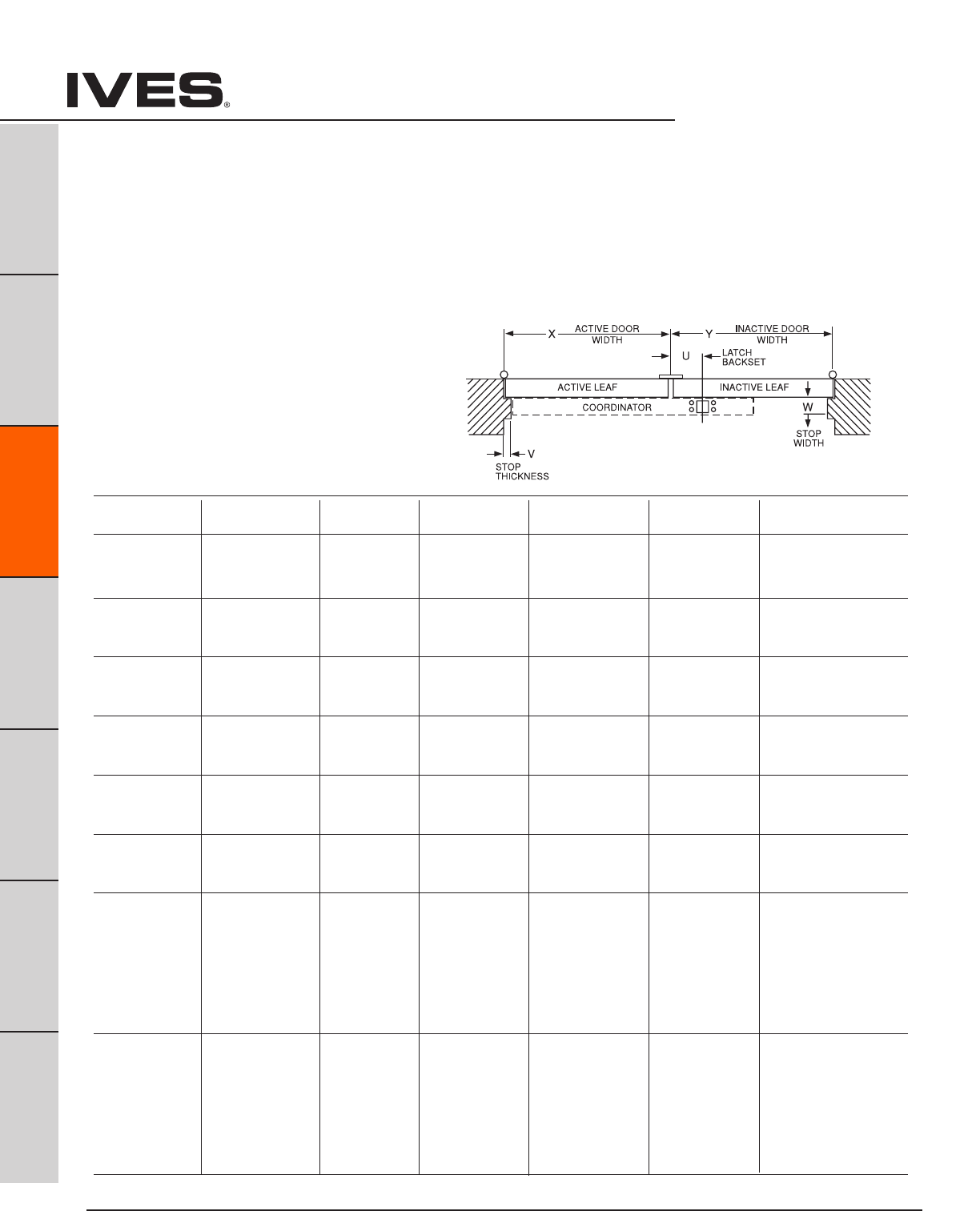
Ives Architectural hardware products
C16
Coordinators
Exit Device Exit Device Device Maximum Coordinator Coordinator Mounting Bracket
Manufacturer Number Backset Active Door Size Needed Cutout Type Needed
33" 42"
Von Duprin 5547-F 2-3/8" 43" 52"
Type A None
51" 60"
63" 72"
33" 42" MB1V, MB2V
Von Duprin 8827-F 2-3/4" 43" 52" Type B or MB3V
51" 60" see page C3
63" 72"
33" 42"
Von Duprin 8847-F 2-3/8" 43" 52" Type C None
51" 60"
63" 72"
33/3547 33" 42"
Von Duprin 33/3547-F 2-3/4" 43" 52" Type D None
98/9947 51" 60"
98/9947-F 64" 72"
33/3548 33" 42"
Von Duprin 33/3548-F 2-3/4" 43" 52" Type D None
98/9948 51" 60"
98/9948-F 64" 72"
33/3547WDC 34" 42"
Von Duprin 33/3547WDC-F 1-5/16" 44" 52" Type E None
98/9947WDC 52" 60"
98/9947WDC-F 65" 72"
17-C
F-17-C
18-C
F-18-C 33" 42"
Falcon XX-C
2-3/4" 43" 52" Type F None
F-XX-C 51" 60"
24-C 63" 72"
F-24-C
25-C
F-25-C
17-C-WDC
F-17-C-WDC
18-C-WDC
F-18-C-WDC 33" 42"
Falcon XX-C-WDC
2-13/16" 43" 52" Type G None
F-XX-C-WDC 51" 60"
24-C-WDC 63" 72"
F-24-C-WDC
25-C-WDC
F-25-C-WDC
Special Factory Preparation for
Use with Vertical Rod Exit Devices
Coordinators may need to be prepared at the factory for use with
some surface or concealed vertical rod exit devices.
(See Chart below)
1. Exit Device Manufacturer and Model No.
2. Active Door Size, “X”
3. Inactive Door Size, “Y”
4. Exit Device Backset, “U”
5. Stop Width, “W”
6. Stop Thickness if other than 5/8", “V”
If the exit device is not listed the following information is needed.
B
Pulls & Plates
A
Hinges & Pivots
C16
Flush Bolts & Coordinators
D
Latches, Catches & Bolts
E
Stops
F
Exterior Hardware
G
Miscellaneous Hardware
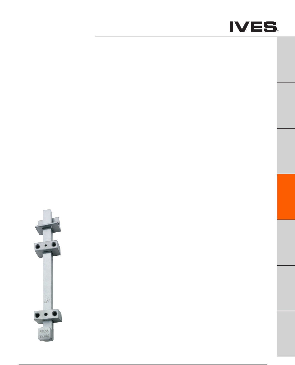
Ives Architectural hardware products D1
Surface Bolts, Latches & Catches
B
Pulls & Plates
A
Hinges & Pivots
C
Flush Bolts & Coordinators
D1
Latches, Catches & Bolts
E
Stops
F
Exterior Hardware
G
Miscellaneous Hardware
Table Of Contents
Surface Bolts page
SB360 Surface Bolt .........................................................D2
SB453 Surface Bolt ..........................................................D2
SB1600 Surface Bolt ........................................................D3
SB1601M1 Surface Bolt ......................................................D3
SB1601M2 Surface Bolt ......................................................D3
40 Surface Bolt, Decorative ..................................................D4
253 Surface Bolt, Decorative .................................................D5
S48 Mortise Door Bolt .......................................................D6
054 Dutch Door Bolt .........................................................D6
Door Guards
481 Chain Door Guard ........................................................ D7
482 Solid Bar Door Guard ....................................................D7
Roller Latch
RL30 Roller Latch ...........................................................D8
RL32 Roller Latch ............................................................D8
RL36 Roller Latch ...........................................................D9
RL38 Roller Latch ...........................................................D9
RL1152 Roller Latch .........................................................D10
STK685 Strike Plate ........................................................D10
STK685L Strike Plate ......................................................D10
Angle Stop
AS18 Angle Stop .............................................................D11
AS895 Angle Stop ...........................................................D11
Latches/Catches
CL11 Invisible Latch .........................................................D12
CL12 Invisible Latch ......................................................... D12
CL14 Auxiliary Pusher .......................................................D12
CL21 Ball Catch .............................................................D13
CL21A Ball Catch ............................................................D13
CL22 Ball Catch .............................................................D13
325 Magnetic Catch ........................................................D14
326 Magnetic Catch, Heavy Duty ...........................................D14
327 Magnetic Catch, Heavy Duty ............................................D14
330 Roller Catch ............................................................D15
335 Roller Catch ............................................................D15
336 Roller Catch ............................................................ D15
345 Ball Catch, Adjustable .................................................. D16
347 Ball Catch, Dual Adjustable .............................................D16
349 Ball Catch .............................................................. D16

Ives Architectural hardware products
D2
Surface Bolts
B
Pulls & Plates
A
Hinges & Pivots
C
Flush Bolts & Coordinators
D2
Latches, Catches & Bolts
E
Stops
F
Exterior Hardware
G
Miscellaneous Hardware
SB360 Surface Bolt
• SurfaceBolthas1-1/4"throwformaximumsecurity.
• Jimmy-resistantdesign,boltlocksautomaticallywhenthrown,
can be released only be pressing knob toward door while retracting.
• Idealforalltypesofdoors.
• Availablein12"length
• Unitlocksinboththeupanddownposition.
• Acceptspadlock(notfurnished)withmaximum3/8"diametershackle,
minimum 1-3/4" shackle opening height.
• Unitspackedwithone-wayscrewsforaddedsecurity.
Standard screws also supplied.
• Unitspackedwithbothauniversaltopstrike(US)andamortisebottom
strike (MS).
• Constructedofheavydutysteel.
• OptionalSexBoltsavailable.
• OptionalMortiseStrikeavailable.
Dimensions
Bar: 3/4" Wide x 3/4" Thick
Overall Width: 2-1/32"
Overall Projection: 2-1/16"
Top Strike: 1-1/2" Wide x 1-1/2" Long x 3/16" Thick
Optional Mortise Strike: 1-5/8" Wide x 3-1/2" Long x 1/8" Thick
SB453 Surface Bolt
• SurfaceBolthas1-3/16"throwformaximumsecurity.
• Strongtensionspringspreventcreep.
• Idealforalltypesofdoors.
• Available8"&12"lengths.
• Unitspackedwithstandardscrewsforaddedsecurity.
• Unitspackedwithbothauniversaltopstrike(US)and
a mortise bottom strike (MS).
• Constructedofheavydutysteel.
• OptionalSexBoltsavailable.
• OptionalThruBoltsavailable.
Dimensions
Bar: 3/4" Wide x 1/4" Thick
Overall Width: 2-1/32"
Overall Projection: 1-5/16"
Top Strike: 1-1/2" Wide x 1-1/2" Long x 3/16" Thick
Bottom Strike: 1-5/8" Wide x 3-1/2" Long x 1/8" Thick
Finishes
Ives Number US2C
BHMA 603
Meets ANSI/BHMA A 156.16
UL listed 3 hour fire door, up to 10'0"
Miami Dade County NOA Listed
Meets ANSI/BHMA A156.16 L84161
UL listed 3 hour fire door, up to 10'0"
Finishes
Ives Number US2C US3 US4* US10 US10B US26D
BHMA 603 632 633 639 640 652
* only available in 8” bolt length.
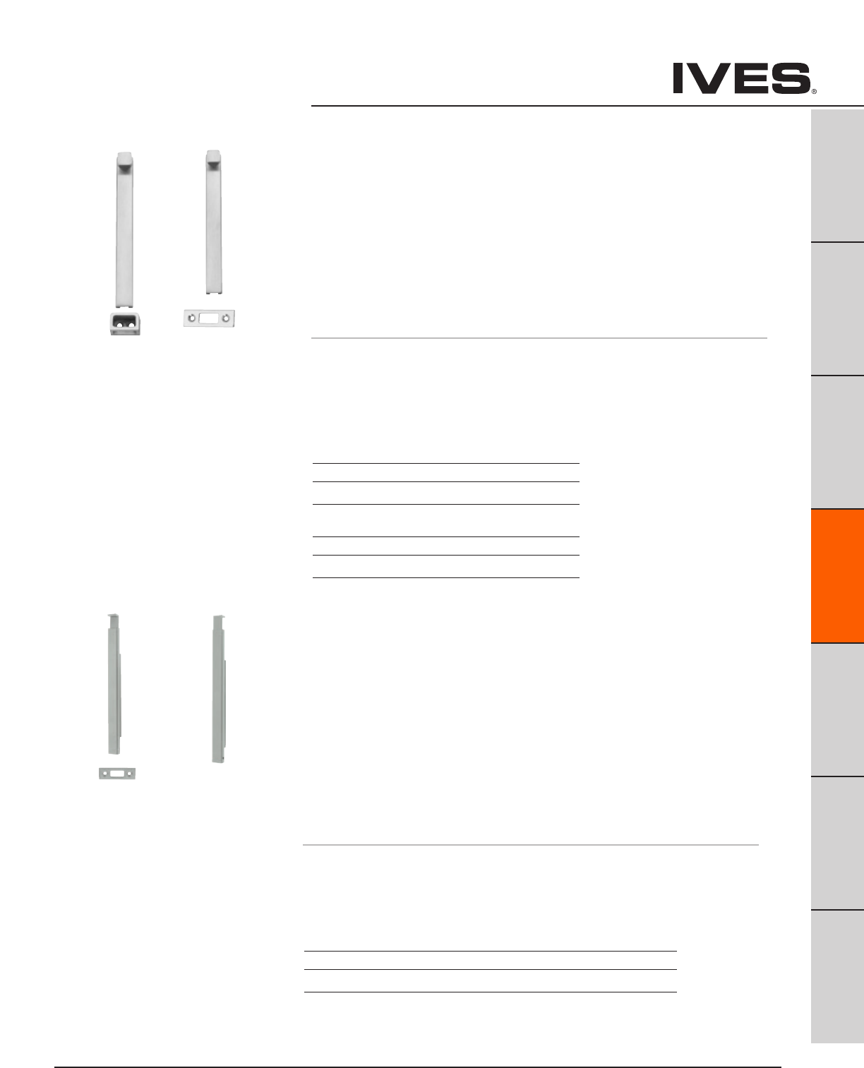
Ives Architectural hardware products D3
Surface Bolts
B
Pulls & Plates
A
Hinges & Pivots
C
Flush Bolts & Coordinators
D3
Latches, Catches & Bolts
E
Stops
F
Exterior Hardware
G
Miscellaneous Hardware
SB1600 Surface Bolt
• StandardSurfaceBolthas1"throwformaximumsecurity.
• Idealforalltypesofdoors.
• Fullyconcealedmountingpreventsvandalism.
• Availableinlockingversion.Unitlocksinboththeupanddown
position. Locking Bolts are furnished with 2 keys in 4 keying variations.
• Unitspackedwithwoodandmachinescrewstomeetmostfieldconditions.
• Unitsavailablewitheitherauniversaltopstrike(T)oraflatbottomstrike(B).
• 1630Seriesisconstructedofheavydutysteel.
• 1640Seriesisconstructedofbrass.
• Optionalsexboltsavailable
Dimensions
Body: 8" Long x 7/8" Wide x 3/4" Thick,
Overall Knob or Lock Housing Projection: 1-1/2"
Top Strike: 1-1/4" Wide x 7/8" Tall x 15/16" Deep
Bottom Strike: 3" Long x 1" Wide x 1/8" Thick
SB1630 Finishes steel
Ives Number US2G US10B US26D
BHMA 604 640 652
SB1640 Finishes brass
Ives Number US3 US10B US26D
BHMA 605 613 626
1630 meets ANSI/BHMA A156.16, L84161 and UL
listed 3 hour fire doors up to 8'0" in height.
1640 meets ANSI/BHMA A156.16, L24161.
SB1600M1
SB1600M2 Surface Bolt
• StandardSurfaceBolthas3-1/2"throwformaximumsecurityandfordoors
with larger undercuts.
• Sleekhandledesign.
• Idealforalltypesofdoors.
• Fullyconcealedmountingpreventsvandalism.
• Availableinlockingversion.Unitlocksinboththeupanddownposition.
Locking bolts are furnished with 2 keys in 4 keying variations.
• Unitspackedwithwoodandmachinescrewstomeetmostfieldconditions.
• Unitsavailablewitheitherauniversaltopstrike(T)oraflatbottomstrike(B).
• Constructedofheavydutysteel.
• Optionalsexboltsavailable
Dimensions
Bar: 11" Long x 3/4" Wide x 3/4" Thick, locking version 1-1/2" Thick
Top Strike: 1-1/4" Wide x 7/8" Tall x 15/16" Deep
Bottom Strike: 3" Long x 1" Wide x 1/8" Thick
Finishes
Ives Number SP4 SP10 SP28 SP313 SPBLK
BHMA 706 691 689 695 622
UL listed 3 hour fire doors up to 8'0" in height.
SB1600M1 SB1600M2

Ives Architectural hardware products
D4
Decorative Surface Bolts
B
Pulls & Plates
A
Hinges & Pivots
C
Flush Bolts & Coordinators
D4
Latches, Catches & Bolts
E
Stops
F
Exterior Hardware
G
Miscellaneous Hardware
40 Decorative Surface Bolt
• Concealedscrewdesignenhancesappearanceandsecurity.
• Exceptionalstrengthanddurabilityprovidedbyinterlocking
construction of heavy gauge track and rod.
• Permanentstoppreventsroddisengagementfromtrack.
• Tensionspringholdsboltindesiredposition.
• Trackassuressmoothoperationandinterlockswithsideedgesof
rod to eliminate marring.
• Decorative5/8"diameterknobdesignedtofacilitateboltoperation.
• Madefromextrudedbrassoraluminum.
• Availablein3",4"and6"lengths.
• PackedwithbothUniversalandMortiseStrikes.
Dimensions
Throw: 15/16"
Projection: 3/4"
Width: 11/16"
Length: 3", 4" or 6"
Meets ANSI/BHMA A156.16
Finishes brass
Ives Number B3 B5 B10B B15 B26 B26D
BHMA 605 609 613 619 625 626
Finishes aluminum
Ives Number A3* A15* PA28
BHMA 666 670 628
* only available 3” bolt Schlage Carded.
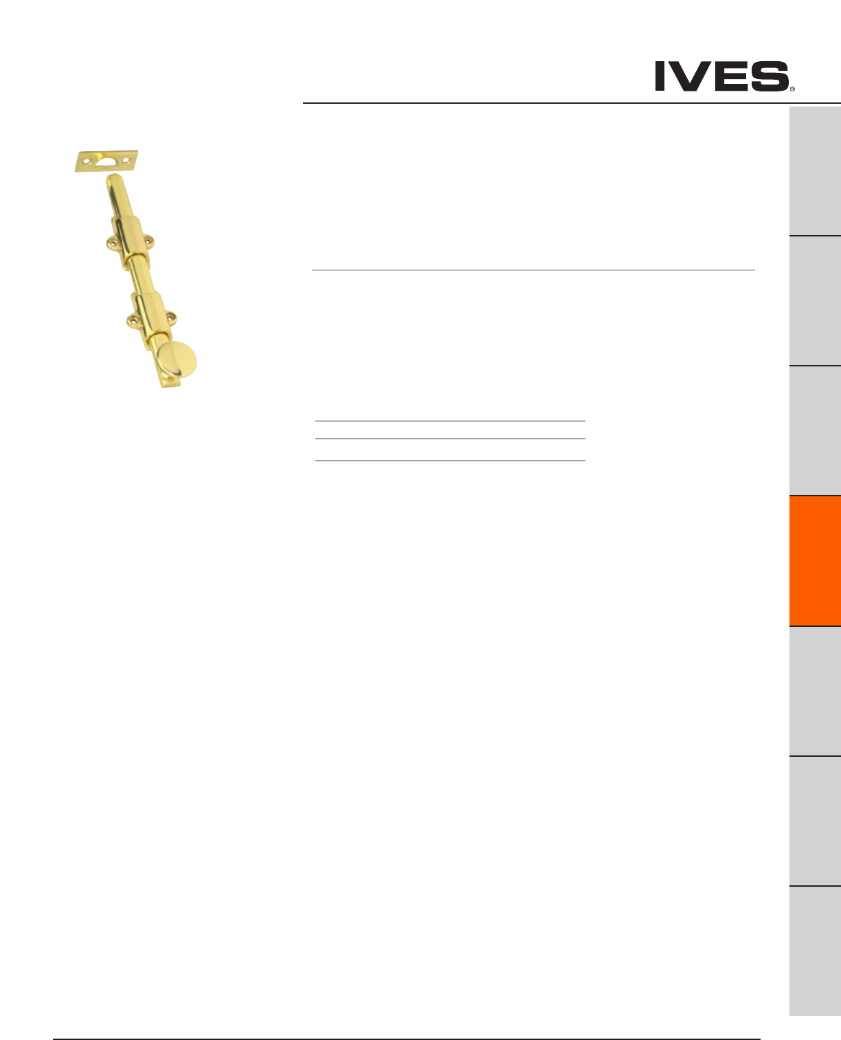
Ives Architectural hardware products D5
Decorative Surface Bolts
B
Pulls & Plates
A
Hinges & Pivots
C
Flush Bolts & Coordinators
D5
Latches, Catches & Bolts
E
Stops
F
Exterior Hardware
G
Miscellaneous Hardware
253 Decorative Surface Bolt
• Heavyduty,decorativeboltidealwhereextrastrengthrequired
• Decorative1-1/4"diameterknobfitswellwithanydécorand
designed to facilitate bolt operation.
• Madefromsolidbrass.
• Availablein8"and12"lengths.
• PackedUniversalStrike(US)&MortiseStrike(MS).
Dimensions
Throw: 1-1/8"
Projection: 1-5/16"
Half Round Rod: 5/8"
Overall Width: 1-5/8"
Length: 8" or 12"
Meets ANSI/BHMA A156.16 Finishes
Ives Number B3 B10B B26D
BHMA 605 613 626
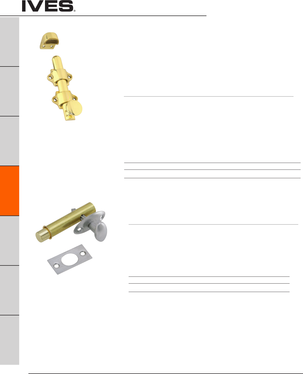
Ives Architectural hardware products
D6
Dutch Door & Mortise Door Bolts
B
Pulls & Plates
A
Hinges & Pivots
C
Flush Bolts & Coordinators
D6
Latches, Catches & Bolts
E
Stops
F
Exterior Hardware
G
Miscellaneous Hardware
054 Dutch Door Bolt
• Practical,rugged,attractiveboltforapplicationondutchdoors
as well as other areas.
• Chamferedrodenddrawsthetwoleavesofdoortightlytogether.
• Sufficienttoleranceprovidedinstrikeopeningtoallowformisalignment
of door leaves and also prevents binding of bolt.
• Decorative1"diameterknobdesignedtofacilitateboltoperation.
• Madefromsolidbrass.
• PackedwithStandardStrike(SS),MortiseStrike(MS)and
Universal Strike (US).
Dimensions
Throw: 5/8"
Projection: 1-1/8"
Half Round Rod: 5/8"
Overall Width: 1-5/8"
Rod Length: 4-1/4"
Overall Length: Specify 4-3/8" (Including Knob)
Finishes
Ives Number B3 B4 B10 B10B B15 B26 B26D
BHMA 605 606 612 613 619 625 626
Finishes brass
Ives Number B3 B5 B10B B15 B26 B26D
BHMA 605 609 613 619 625 626
S48 Mortise Door Bolt
• Brassovalturnknobandescutcheon.
• Steelboltforextrastrength.
Rack is milled for precision fit with pinion.
Dimensions
Backset: 1-3/4"
Bolt Throw: 1/2"
Bolt Diameter: 1/2"
Case: 2-1/2" Long x 9/16" diameter
Strike: 1-3/4" High x 7/8" Wide
Meets ANSI/BHMA A156.16.
Meets ANSI/BHMA A156.16.
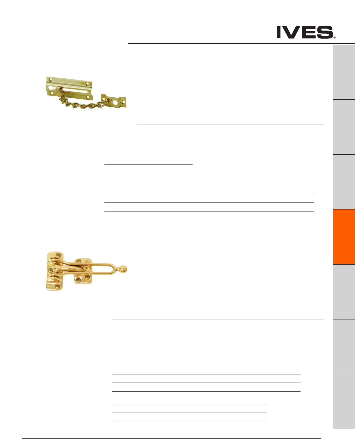
Ives Architectural hardware products D7
Door Guards
B
Pulls & Plates
A
Hinges & Pivots
C
Flush Bolts & Coordinators
D7
Latches, Catches & Bolts
E
Stops
F
Exterior Hardware
G
Miscellaneous Hardware
481 Chain Door Guard
• Permitsthedoortobeslightlyopenedtoallowviewing.
• Narrowchainholdermaintainschaininstationarypositionwhen
door guard is not in use, eliminating marring of door and
frame caused by dangling chain.
• Weldedtwistlinksteelchainfinishedtomatchdoorplate
and chain holder.
• Madefromwroughtbrassorburnishedwroughtsteel.
• Packedwithsheetmetalscrews.
Dimensions
Door Plate: 3-3/8" Long x 1-7/16" Wide
Chain Holder: 1-10/16" High x 3/4" Wide
Chain Length: 4-3/4"
482 Solid Bar Door Guard
• Foruseondoorsthatareflushwithframes.
• Thesolidbar,interlockingwiththeballonthestrikeplate,
permits the door to be slightly opened to allow viewing.
• Thehingedbarallowsthedoorguardtobepositioned180°away
from the door when not in use.
• Edgeguardonly,furnishedwithcastbrassdoorguards,
minimizes the chance for marring the door or frame.
• Strikeplateisdesignedtopreventthesolidbarfrommarringthe
inside of the door when in use.
• Madefromcastbrassorcastaluminum.
• Packedwithsheetmetalscrews.
• ShimsavailableinUS26D(626)only,1/8”or3/8”.Onlyfits482B.
Meets ANSI/BHMA A156.16
Meets ANSI/BHMA A156.16
Finishes brass
Ives Number B3 B26D
BHMA 605 626
Finishes steel
Ives Number F3 F4 F5 F10 F15 F26 F26D F716
BHMA 632 633 638 639 646 651 652
Finishes brass
Ives Number B3 B4 B10 B10B B15 B26 B26D
BHMA 605 606 612 613 619 625 626
Finishes aluminum
Ives Number A3 A5 A26 A26D
BHMA 666 672 702
482B Cast Brass Dimensions 482A Cast Aluminum Dimensions
Strike Plate: 2-5/8" High x 1-1/32" Wide Strike Plate: 2-1/2" High x 7/8" Wide
Holder: 1-3/4" High x 1-1/16" Wide Holder: 2-1/2" High x 15/16" Wide
Arm Length: 4-3/4" Arm Length: 3-13/16"
Edge Guard: 1-1/8" High x 1-1/32" Wide

Ives Architectural hardware products
D8
B
Pulls & Plates
A
Hinges & Pivots
C
Flush Bolts & Coordinators
D8
Latches, Catches & Bolts
E
Stops
F
Exterior Hardware
G
Miscellaneous Hardware
Roller Latches
RL30 Roller Latch
• Actuationissimple,closingofthedoorcausestherollertofallinthe
depression of the strike, thereby holding the door closed.
• Theprojectionoftherolleriseasilyadjustedusingadjustingscrews
on the face of the unit.
• Maximumprojectionoftherolleris3/8"allowingforvariancein
the door clearance.
• NylonRollerStandard.
• ForgedBrassConstruction.
• OptionalStrike—A—ASA.
• Optional—F—BrassRoller,mustbeorderedseparately.
Dimensions
Body: 1" Wide x 3-3/8" High x 1-11/16" Deep
Strike: 1-11/16" Wide x 2-1/4" High x 5/32" Thick, Lip to Center- 1-5/16"
Optional ASA Strike: 1-1/4" Wide x 4-7/8" High x 3/32" Thick, Lip to Center- 1-1/4"
RL32 Roller Latch
• Actuationissimple,closingofthedoorcausestherollertofall
in the depression of the strike, thereby holding the door closed.
• Theprojectionoftherolleriseasilyadjustedbyturningknurled
knob on back of latch.
• Maximumprojectionoftherolleris1/2"allowingforvariancein
the door clearance.
• Fitsheavy-dutycylindricallockcutout.
• NylonRollerStandard.
• Non-handed.
• BrassConstruction.
• OptionalStrike—A—ASA.
Dimensions
Body: 1-1/8" Wide x 2-1/4" High x 2-1/4" Deep
Strike: 1-1/8" Wide x 2-3/4" High x 3/32" Thick, Lip to Center- 1-1/4"
Optional ASA Strike: 1-1/4" Wide x 4-7/8" High x 3/32" Thick, Lip to Center- 1-1/4"
Meets ANSI/BHMA A156.16, E19091
Meets ANSI/BHMA A156.16, E19091
Finishes brass
Ives Number US3 US4 US10 US10B US26 US26D
BHMA 605 606 612 613 625 626
Finishes brass
Ives Number US3 US4 US10 US10B US26 US26D
BHMA 605 606 612 613 625 626
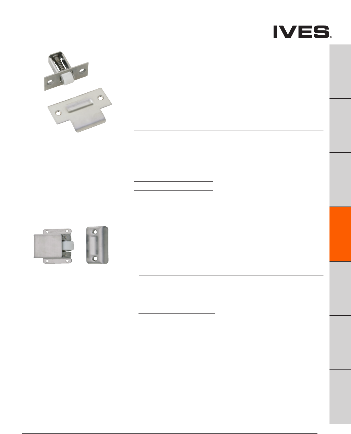
Ives Architectural hardware products D9
B
Pulls & Plates
A
Hinges & Pivots
C
Flush Bolts & Coordinators
D9
Latches, Catches & Bolts
E
Stops
F
Exterior Hardware
G
Miscellaneous Hardware
Roller Latches
RL36 Roller Latch
• Actuationissimple,closingofthedoorcausestherollertofallin
the depression of the strike, thereby holding the door closed.
• Theprojectionoftherolleriseasilyadjustedbyturningslotted
screw on back of latch.
• Maximumprojectionoftherolleris5/16"allowingforvariance
in the door clearance.
• Fitscylindricallockcutout.
• NylonRoller.
• Non-handed.
• StainlessSteelConstruction.
• OptionalStrike–A—ASA.
Dimensions
Body: 1" Wide x 2-1/4" High x 2" Deep
Strike: 1-1/8" Wide x 2-3/4" High x 3/32" Thick, Lip to Center- 1-1/4"
Optional ASA Strike: 1-1/4" Wide x 4-7/8" High x 3/32" Thick, Lip to Center- 1-1/4"
Meets ANSI/BHMA A156.16, L57082
Meets ANSI/BHMA A156.16, L27092
Finishes Stainless Steel
Ives Number US32D
BHMA 630
RL38 Roller Latch
• Actuationissimple,closingofthedoorcausestherollertofallinthe
depression of the strike, thereby holding the door closed.
• Theprojectionoftherolleriseasilyadjustedbyturningslottedscrew.
• Maximumprojectionoftherolleris3/8"allowingforvarianceinthe
door clearance.
• NylonRoller.
• Non-handed.
• StainlessSteelConstruction.
Dimensions
Body: 1-3/8" Wide x 2" High x 7/8" Deep
Strike: 1" Wide x 2-1/8" High x 3/8" Deep
Finishes Stainless Steel
Ives Number US32D
BHMA 630
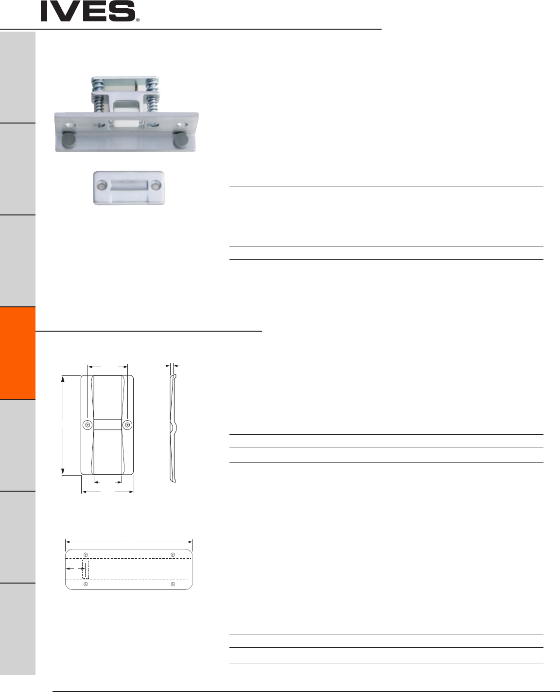
Ives Architectural hardware products
D10
B
Pulls & Plates
A
Hinges & Pivots
C
Flush Bolts & Coordinators
D10
Latches, Catches & Bolts
E
Stops
F
Exterior Hardware
G
Miscellaneous Hardware
Roller Latches
RL1152 Roller Latch
• CombinationofRL30RollerLatchandAngleStop.
• Actuationissimple,closingofthedoorcausestherollerto
fall in the depression of the strike, thereby holding the
door closed.
• Theprojectionoftherolleriseasilyadjustableusing
adjusting screws on the face of the unit.
• Maximumprojectionoftherolleris3/8"allowingfor
variance in the door clearance.
• NylonRollerStandard.
• ForgedBrassConstruction.
• Optional—F—BrassRoller,mustbeorderedseparately.
Dimensions
Body: 1-1/2" Wide x 4-1/2" High x 1-3/4" Deep with 3/4" Angle
Strike: 1-1/8" Wide x 2-1/4" High x 5/32" Thick
Optional Strike
STK685 Strike
• Custommakestrikefordoorsthatswingbothdirections.
For use with roller latches.
• Constructedof3/32"brass.
• Dimpleofstrikecenteredonstrike.
• Specifyframedepth-A.Overallstrikelengthwillbe
A + 3/8” to accommodate 3/16” lip on each side
A
685 A&B Dim. Variable
1-11/16"
1-5/32"
2-1/4"
3/32"
A
B
685L
STK685L Strike
• Custommakestrikefordoorsthatswingbothdirections.
For use with roller latches.
• Constructedof3/32"brass.
• Locationofstrikedimpleisvariable.
Please specify frame depth - A and location of dimple
from edge of frame - B. Dimple will be located B + 3/16"
to accommodate lip.
• Specifyframedepth-A.Overallstrikelengthwillbe
A + 3/8” to accommodate 3/16” lip on each side
Finishes
Ives Number US3 US4 US10 US10B US26 US26D
BHMA 605 606 612 613 625 626
Finishes
Ives Number US3 US4 US10 US10B US26 US26D
BHMA 605 606 612 613 625 626
Finishes
Ives Number US3 US4 US10 US10B US26 US26D
BHMA 605 606 612 613 625 626
Meets ANSI/BHMA A156.16, E19111
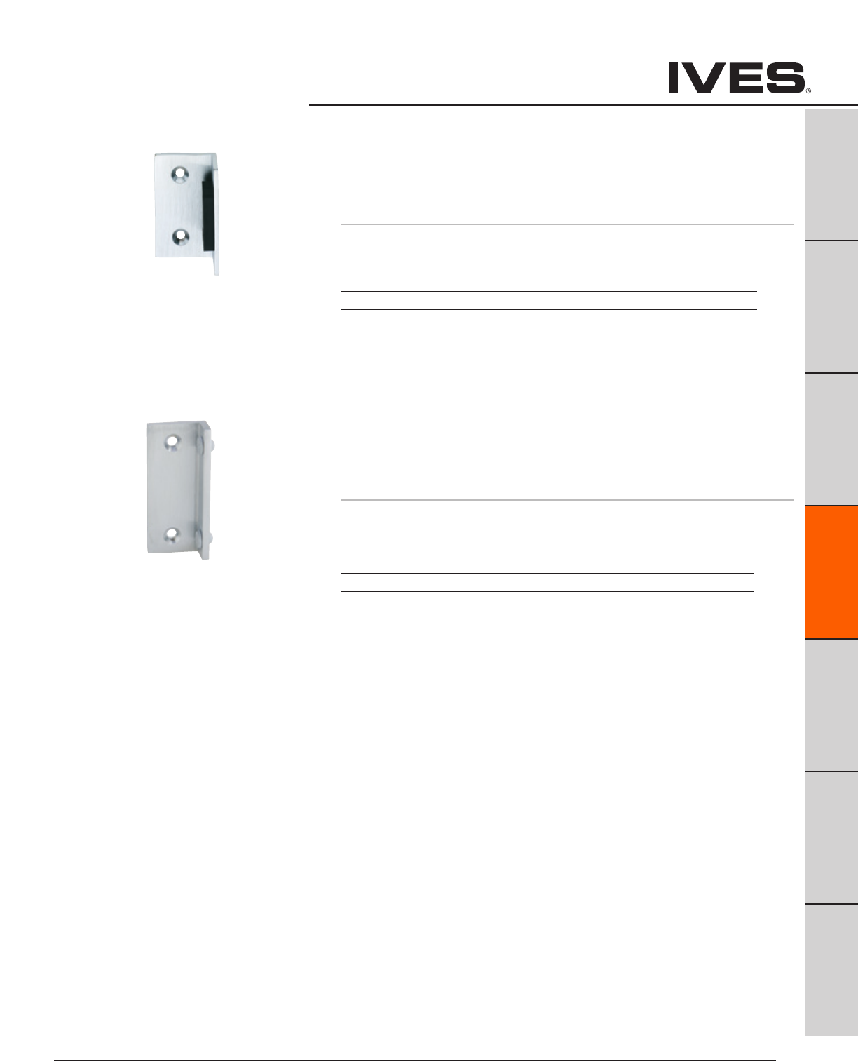
Ives Architectural hardware products D11
B
Pulls & Plates
A
Hinges & Pivots
C
Flush Bolts & Coordinators
D11
Latches, Catches & Bolts
E
Stops
F
Exterior Hardware
G
Miscellaneous Hardware
Angle Stops
AS895 Angle Stop
• Surfaceappliedstopforsingledoors.
• Largerubberbumpertoensurequietoperation.
• Constructedof1/8"BrassAngle.
Dimensions
1-1/2" Wide x 1" Angle x 2-1/2" Long
AS18 Angle Stop
• Surfaceappliedstopforsingleanddoubledoors.
• IncludesSR64doorsilencerstoensurequietoperation.
SR64 silencers are replaceable.
• Constructedof3/16"BrassAngle.
Dimensions
1-1/2" Wide x 3/4" Angle x 3-1/2" Long
Finishes
Ives Number US3 US4 US10 US10B US26 US26D
BHMA 605 606 612 613 625 626
Finishes
Ives Number US3 US4 US10 US10B US26 US26D
BHMA 605 606 612 613 625 626

Ives Architectural hardware products
D12
B
Pulls & Plates
A
Hinges & Pivots
C
Flush Bolts & Coordinators
D12
Latches, Catches & Bolts
E
Stops
F
Exterior Hardware
G
Miscellaneous Hardware
Invisible Latches
CL11 Invisible Latch
• Invisiblelatchisidealforinstallationswherenovisiblelatchisdesired.
• Unitcanbeinstalledatthetop,bottomorsideofthedoor.
• Canbemortisedintothestoporsurfacemountedtothestop.
• Recommendedforuseonsmallpanels,cabinetdoorsorlightweight
closet doors.
• Operationissimple,latchingisaccomplishedbyaslightpush.
To unlatch the door, a harder push releases the door and pushes the
door out.
• Brassandplasticconstruction.
• Applies13poundstoopenthedoor.
Dimensions
Body: 1-1/4" Wide x 1-7/8" High x 7/16" Thick
Strike: 9/16" Wide x 1-5/16" High x 9/16" High
Meets ANSI/BHMA 156.9, B03272
Finishes
Ives Number US3 US4 US10 US26D
BHMA 605 606 612 626
Finishes
Ives Number US3 US4 US10 US26D
BHMA 605 606 612 626
Finishes
Ives Number US3 US4 US10 US26D
BHMA 605 606 612 626
CL12 Invisible Latch
• Invisiblelatchisidealforinstallationswherenovisiblelatchisdesired.
• Unitcanbeinstalledatthetop,bottomorsideofthedoor.
• Canbemortisedintothestoporsurfacemountedtothestop.
• Recommendedforuseonlargerpanelsorregularsizedoors.
• Operationissimple,latchingisaccomplishedbyaslightpush.
To unlatch the door, a harder push releases the door and pushes the
door out.
• Brassandplasticconstruction.
• Applies27poundstoopenthedoor.
Dimensions
Body: 1-1/4" Wide x 2-1/4" High x 9/16" Thick
Strike: 5/8" Wide x 1-13/16" High x 9/16" Projection
Meets ANSI/BHMA A156.9, B03272
CL14 Auxiliary Pusher
• AidintheoperationoftheCL11andCL12wherehingesor
surrounding conditions prevent smooth operation of doors.
• Provides1-1/16"throw.
• Nylonpusher.
• Brassconstruction.
• Applies10poundstoopenthedoor.
Dimensions
Body: 2-15/16" Long x 1-11/16" Wide x 5/8" Deep
Meets ANSI/BHMA A156.9, B13282
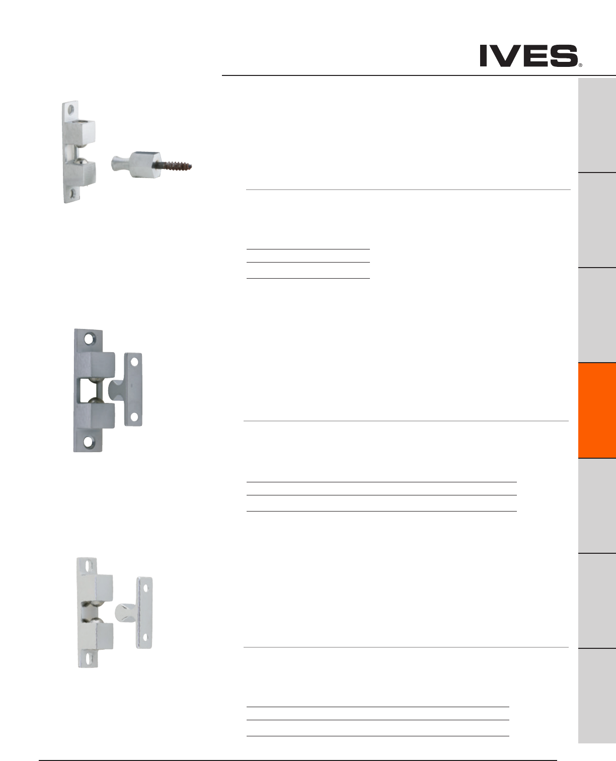
Ives Architectural hardware products D13
B
Pulls & Plates
A
Hinges & Pivots
C
Flush Bolts & Coordinators
D13
Latches, Catches & Bolts
E
Stops
F
Exterior Hardware
G
Miscellaneous Hardware
Ball Catches
CL21A Ball Catch
• Four-waycatchwithplatetypestrike.
• Idealforclosetdoors,accessdoors,hingedopeningsandnumerous
other applications.
• Thestrikeslidesbetweentwostainlesssteelballsthatareunder
spring tension. As the strike engages, the door is held tightly shut.
• Strikecanenterbodyfromanydirection.
• Springtensioniseasilyadjustedtosuitfieldconditions.
• Bodycanbesurfaceappliedormortised.
• Brassconstruction.
Dimensions
Body: 3/4" Wide x 3" High x 3/4" Deep
Strike: 7/16" Wide x 1-3/4" High x 7/8" Deep
CL22 Ball Catch
• Three-waycatchwithplatetypestrike.
• Idealforsmallercabinetdoorsorpanels.
• Thestrikeslidesbetweentwostainlesssteelballsthatareunder
spring tension. As the strike engages, the door is held tightly shut.
• Strikecanenterbodyfromeithersideorfront.
• Springtensioniseasilyadjustedtosuitfieldconditions.
• Bodycanbesurfaceappliedormortised.
• Brassconstruction.
Dimensions
Body: 1/2" Wide x 2-3/16" High x 1/2" Deep
Strike: 3/8" Wide x 1-3/8" High x 5/8" Deep
CL21 Ball Catch
• Four-waycatchwithhexagonstud.
• Idealforholdingmediumdutydoors.
• Thestrikeslidesbetweentwostainlesssteelballsthatareunder
spring tension. As the strike engages, the door is held tightly shut.
• Strikecanenterbodyfromanydirection.
• Springtensioniseasilyadjustedtosuitfieldconditions.
• Bodycanbesurfaceappliedormortised.
• Brassconstruction.
Dimensions
Body: 3/4" Wide x 3" High x 3/4" Deep
Strike: 3/4" Wide Hex x 1-1/2" High
Meets ANSI/BHMA A156.9
Meets ANSI/BHMA A156.9, B13292
Meets ANSI/BHMA 156.9, B13302.
Finishes brass
Ives Number US26D
BHMA 626
Finishes brass
Ives Number US3 US4 US10 US26 US26D
BHMA 605 606 612 625 626
Finishes brass
Ives Number US3 US4 US10 US26 US26D
BHMA 605 606 612 625 626
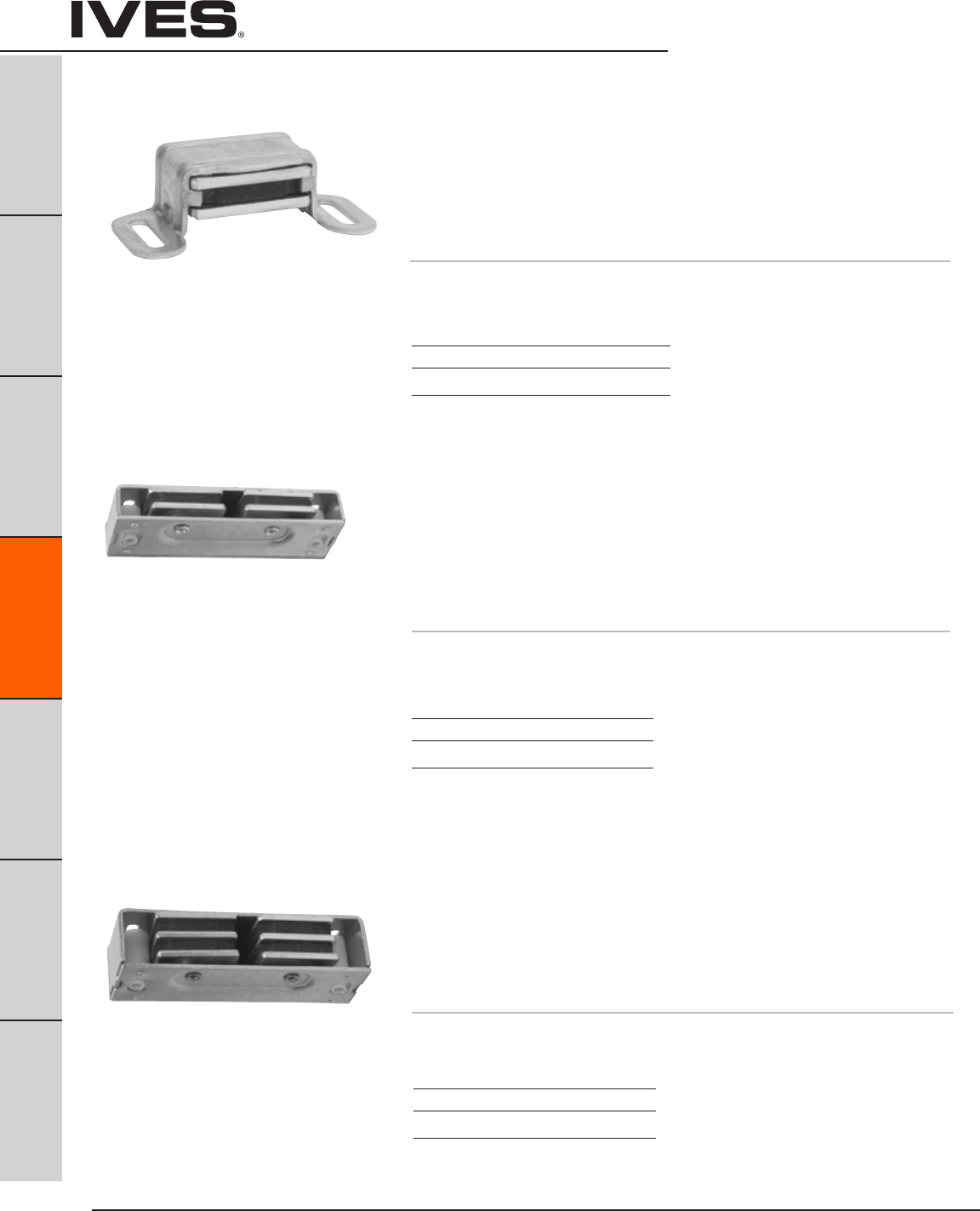
Ives Architectural hardware products
D14
B
Pulls & Plates
A
Hinges & Pivots
C
Flush Bolts & Coordinators
D14
Latches, Catches & Bolts
E
Stops
F
Exterior Hardware
G
Miscellaneous Hardware
Magnetic Catches
325 Magnetic Catch
• Doublepole.
• Selfaligningmagnetinsuresmaximumpull.
• Casedesignallowseasymagnetadjustmentoncabinet
or small door applications.
• Aluminumcase.
• Packedwithsheetmetalscrews.
• 5lbs.LoadCapacity
Dimensions
Case: 1-1/8" wide x 2-1/16" Long x 5/8" Thick
327 Super-Mite® Heavy Duty Magnetic Catch
• Dualtriplepole.
• Self-aligningmagnetsinsuremaximumpull.
• Canbesurfacemountedormortised.
• Aluminumcase.
• Packedwithsheetmetalscrews,2shortstrikesand
1 long strike.
• 14lbs.LoadCapacity
Dimensions
Case: 1" Wide x 3-1/8" Long x 3/4" Thick
326 Mighty-Mite® Heavy Duty Magnetic Catch
• Dualdoublepole.
• Self-aligningmagnetsinsuremaximumpull.
• Canbesurfacemountedormortised.
• Aluminumcase.
• Packedwithsheetmetalscrews,2shortstrikesand
1 long strike.
• 9lbs.LoadCapacity
Dimensions
Case: 1" Wide x 3-1/8" Long x 9/16" Thick
Finishes aluminum
Ives Number A3 A92
BHMA 666 673
Finishes aluminum
Ives Number A3 A92
BHMA 666 673
Finishes aluminum
Ives Number A3 A92
BHMA 666 673
Meets ANSI/BHMA A156.9 B43171.
Meets ANSI/BHMA A156.9 B43161.
Meets ANSI/BHMA A156.9 B43161.

Ives Architectural hardware products D15
B
Pulls & Plates
A
Hinges & Pivots
C
Flush Bolts & Coordinators
D15
Latches, Catches & Bolts
E
Stops
F
Exterior Hardware
G
Miscellaneous Hardware
Roller Catches
335 Roller Catch
• Smooth,positivelatchingactioninsuredbypowerfulconicalspring.
• Durablenylonrollerinsuresquietoperation.
• Adjustabletension.Adjustmentscanbevariedfrom4to17lbs.
of holding power making possible a wide range of door performance.
• Easilyinstalledonthindoors.
• Fulllipstylestrikedesignedforsimplifiedmortising.
• Madefromwroughtbrassorwroughtsteel.
• Packedwithsheetmetalscrews.
Dimensions
Face Plate: 7/8" Wide x 2-1/4" High
Bore: 1-3/4" Deep x 13/16" Diameter
Strike: 1-5/8" Wide x 2-1/4" High, Lip to center- 1-3/16"
336 Roller Catch
• Smooth,positivelatchingactioninsuredbypowerfulconicalspring.
• Durablenylonrollerinsuresquietoperation.
• Adjustabletension.Adjustmentscanbevariedfrom4to17lbs.
of holding power making possible a wide range of door performance.
• Easilyinstalledonthindoors.
• Standardboxtypestrikedesignedforneatappearance.
• Madefromwroughtbrassorwroughtsteel.
• Packedwithsheetmetalscrews.
Dimensions
Face Plate: 7/8" Wide x 2-1/4" High
Bore: 13/16" Diameter x 1-3/4" Deep
Strike: 7/8" Wide x 2-1/4" High, Lip to center- 1-1/8"
Meets ANSI/BHMA A156.16 L27081 for brass
and L87081 for steel.
Meets ANSI/BHMA A156.16 L27081 for brass
and L87801 for steel.
Finishes
Ives Number B3 B5 B10 B10B B15 B26 B26D
BHMA 605 609 612 613 619 625 626
330 Roller Catch
• Independentrollersallowpositiveactionandself-alignment.
• Cushionedrollersabsorbshockandnoise,holddoorawayfromcabinet.
• Applicationallowsforeasyadjustment.
• Madefromwroughtsteel.
• Packedwithscrewsandbrads.
Dimensions
Case: 1-1/4" High x 11/16" Wide
Strike: 1-1/4" High x 3/8" Wide
Meets ANSI/BHMA A156.9 B83071.
Finishes
Ives Number F2C
BHMA 603
Finishes
Ives Number B3 B4 B5 B10 B10B B15 B26 B26D
BHMA 605 606 609 612 613 619 625 626

Ives Architectural hardware products
D16
B
Pulls & Plates
A
Hinges & Pivots
C
Flush Bolts & Coordinators
D16
Latches, Catches & Bolts
E
Stops
F
Exterior Hardware
G
Miscellaneous Hardware
Ball
Catches
345 Adjustable Ball Catch
• Idealforcabinetsandsmallinteriordoors.
• Freerollingballinsuressmooth,positiveandtrouble-freeaction.
• Adjustablethreadedbarrelcompensatesforvariousdoorclearances.
• Adjustablespringtension.
• Madefromwroughtbrass.
Dimensions
Face Plate: 3/4" Wide x 1-1/2" High
Bore: 1" Deep x 9/16" Diameter
Strike: 25/32" Wide x 1-1/2" High, Lip to center- 13/32"
347 Dual Adjustable Ball Catch
• Forcatchindoorinstallations.
• Dualadjustmentfordoorclearanceandholdingstrength.
• Lipstrikeisdesignedforusewherestrikeismountedinjamb.
• Freerollingballinsuressmooth,positiveandtrouble-freeaction.
• Adjustablethreadedbarrelcompensatesforvariousdoorclearances.
• Adjustablespringtension.
• Madefromwroughtbrass.
Dimensions
Face Plate: 1" Wide x 2-1/8" High
Bore: 7/8" Diameter x 1-3/8" Deep
Strike: 1-3/8" Wide x 2-1/8" High, Lip to center- 7/8"
349 Ball Catch
• Forcatchindoorinstallations.
• Radiusedcornersalloweasyinstallationwitharouter.
• Dualadjustmentfordoorclearanceandholdingstrength.
• Lipstrikeisdesignedforusewherestrikeismountedinjamb.
• Freerollingballinsuressmooth,positiveandtrouble-freeaction.
• Adjustablethreadedbarrelcompensatesforvariousdoorclearances.
• Adjustablespringtension.
• Madefromwroughtbrass.
Dimensions
Face Plate: 1" Wide x 2-1/8" High
Bore: 7/8" Diameter x 1-3/8" Deep
Strike: 1-3/8" Wide x 2-1/8" High, Lip to center- 7/8"
Meets ANSI/BHMA A156.9 B23013.
Meets ANSI/BHMA A156.9 B23013.
Meets ANSI/BHMA A156.9 B23013.
Finishes brass
Ives Number B3 B5 B10 B10B B15 B26 B26D
BHMA 605 609 612 613 619 625 626
Finishes brass
Ives Number B3 B4 B5 B10 B10B B15 B26 B26D
BHMA 605 606 609 612 613 619 625 626
Finishes brass
Ives Number B3 B4 B5 B10 B10B B15 B26 B26D B716
BHMA 605 606 609 612 613 619 625 626
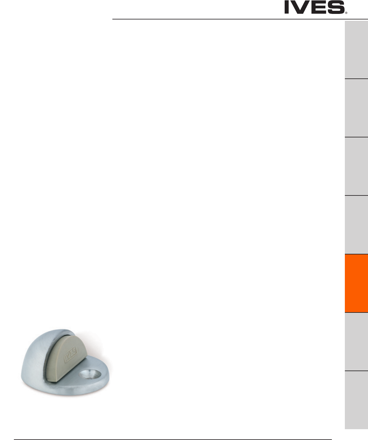
Ives Architectural hardware products E1
Door Stops
B
Pulls & Plates
A
Hinges & Pivots
C
Flush Bolts & Coordinators
D
Latches, Catches & Bolts
E1
Stops
F
Exterior Hardware
G
Miscellaneous Hardware
Table Of Contents
Floor Stops page
FS13 Floor Stop ........................................................E2
R14 Riser ..............................................................E2
FS17 Floor Stop ........................................................E2
FS436 Floor Stop ......................................................E3
FS438 Floor Stop ......................................................E3
R435 Riser ............................................................E3
R437 Riser .............................................................E3
FS439 Floor Stop ......................................................E4
FS410 Floor Stop ......................................................E4
FS18, FS18L Floor Stop ................................................E5
FS434 Floor Stop ......................................................E5
430 Floor Stop ........................................................E5
FS441, FS441WS Floor Stop ...........................................E6
FS444, FS448 Floor Stop ..............................................E6
Floor Stop & Holder
FS9 Floor Stop & Semi-automatic Holder .............................. E7
FS40, FS41, FS42, FS43 Floor Stop & Automatic Holder ................E7
FS446, FS450 Floor Stop & Manual Holder ............................E8
FS495, FS496, FS497 Floor Stop & Automatic Holder .................E8
Wall Bumpers/Stops
WS11, WS11X Wall Stop ................................................E9
WS20, WS20X Manual Wall Holder ....................................E9
WS33, WS33X Wall Stop .............................................E10
WS65 Wall Stop ......................................................E10
WS401, WS402 Wall Bumper ..........................................E11
WS404 Wall Bumper ..................................................E11
WS406, WS407 Wall Bumper ........................................E12
411R Wall Bumper ....................................................E13
WS443, WS447 Wall Stop ............................................E14
WS445, WS449 Manual Wall Holder .................................E14
Wall Holders
WS40 Automatic Wall Holder ........................................E15
WS45, WS45X Automatic Wall Holder ...............................E15
Kick Down Holder
FS452 Kick Down Holder .............................................E16
FS455 Kick Down Holder .............................................E16
FS544, FS555 Kick Down Holder ...................................... E17
Plunger Door Holders
FS1153 ................................................................E18
FS1154 ................................................................E18
Roller Bumpers
RB470, RB471, RB472 Roller Bumper ..................................E19
Residential Door stops
060, 061 Flexible Door Stop ......................................... E20
60, 61 Door Base Stop ............................................... E20
63 Flexible Door Stop .................................................E21
64 Door Base Stop ...................................................E21
Hinge Pin Stops
69 .................................................................... E21
70 ....................................................................E22
72Z Residential Door Saver ...........................................E22
73Z Commercial Door Saver ..........................................E22
Silencers
SR64, SR65, SR66 Door Silencer ......................................E23

Ives Architectural hardware products
E2
Floor Stops — Dome
B
Pulls & Plates
A
Hinges & Pivots
C
Flush Bolts & Coordinators
D
Latches, Catches & Bolts
E2
Stops
F
Exterior Hardware
G
Miscellaneous Hardware
FS13 Dome Stop
• StandardFS13forusewherenothresholdisused.
• Heavy-DutyCastDomeStopsconstructedofbrass.
• UniqueriserdesignofR14(below)allowseasyconversionto
threshold application.
• Unitsarepackedwithfastenerssufficientformountinginalltypesof
floor construction, including concrete.
• Replaceablegreyrubberbumper.
Dimensions
Overall Height: 1”
Base Height: 5/32”
Base Diameter: 1-3/4”
Finishes
Ives Number US3 US4 US10 US10B US26 US26D
BHMA 605 606 612 613 625 626
FS17 Dome Stop
• Onepiecedomestopforusewiththresholds.
• Heavy-DutyCastDomeStopsconstructedofbrass.
• Unitsarepackedwithfastenerssufficientformountinginalltypesof
floor construction, including concrete.
• Replaceablegreyrubberbumper.
Dimensions
Overall Height: 1-11/32”
Base Height: 1/2”
Base Diameter: 1-3/4” round
Finishes
Ives Number US3 US4 US10 US10B US26 US26D
BHMA 605 606 612 613 625 626
Meets ANSI/BHMA 156.6, L12141.
Meets ANSI/BHMA 156.6, L12161.
R14 Dome Stop Rise
• AdaptstheFS13DomeStoptothresholduse.
• BrassDieCastConstruction.
Dimensions
Riser Height: 5/16”
Base Diameter: 1-3/4” round
Finishes
Ives Number US3 US4 US10 US10B US26 US26D
BHMA 605 606 612 613 625 626

Ives Architectural hardware products E3
Floor Stops — Dome
B
Pulls & Plates
A
Hinges & Pivots
C
Flush Bolts & Coordinators
D
Latches, Catches & Bolts
E3
Stops
F
Exterior Hardware
G
Miscellaneous Hardware
FS436 Dome Stop
FS438 Dome Stop
• FS436fordoorswithoutthreshold.
• FS438fordoorswiththresholdorundercutdoors.
• Heavy-DutyCastDomeStopsconstructedofbrass,bronzeoraluminum.
• Packedwithwoodscrewandplasticanchor.
Replaceable gray, non-marring rubber bumper.
Dimensions
FS436
Overall Height: 1”
Base Height: 3/16”
Base Diameter: 1-3/4” x 2” Oval
PA D
FLOOR
1" OR
LESS
1"
1-7/16"
R435 Riser for FS436 Dome Stop
R437 Riser for FS438 Dome Stop
• Extrudedaluminum,millfinish.
• R435forconversionofFS436DomeStoptocarpetinstallation.
• R437ForconversionofFS438DomeStoptocarpetinstallation.
• Packedwithwoodscrews,leadshieldandstud.
Specify Tampin (TPN) if required.
Dimensions
Available in 1/4”, 3/8”, 1/2”, 5/8”, 3/4” and 1” height.
FS438
Meets ANSI/BHMA 156.16, L12141 for brass
or bronze and L32141 for aluminum.
Finishes brass
Ives Number US3 US4 US5 US10 US10B US15 US26 US26D B716
BHMA 605 606 609 612 613 619 625 626
Finishes aluminum
Ives Number US28
BHMA 628
FS436
Meets ANSI/BHMA 156.16, L12141 for brass
or bronze and L32141 for aluminum.
FS438
Overall Height: 1-3/8”
Base Height: 9/16”
Base Diameter: 1-3/4” x 2” Oval

Ives Architectural hardware products
E4
Floor Stops
B
Pulls & Plates
A
Hinges & Pivots
C
Flush Bolts & Coordinators
D
Latches, Catches & Bolts
E4
Stops
F
Exterior Hardware
G
Miscellaneous Hardware
FS439 Universal Dome Floor Stop
• HighorLow-RiseMount
• ZincorStainlessSteel
• Spring-loadedRubberContact
• ReplaceableRubberBumper
Dimensions
Overall Height: 1-1/2”
Pad Height: 1-1/8”
Base Height: 1/4”
Base Diameter: 1-7/8”
FS410 Decorative Floor Stop
• Non-directional
• CastBrassConstruction
• ReplaceableRubberBumper
Dimensions
Overall Height: 1-1/2”
Bumper Thickness: 1/4”
Diameter: 1-1/4”
Finishes
Ives Number US3 US4 US10B US26D US32D
BHMA 677 678 704 682 630
Finishes
Ives Number US3 US26D
BHMA 605 626
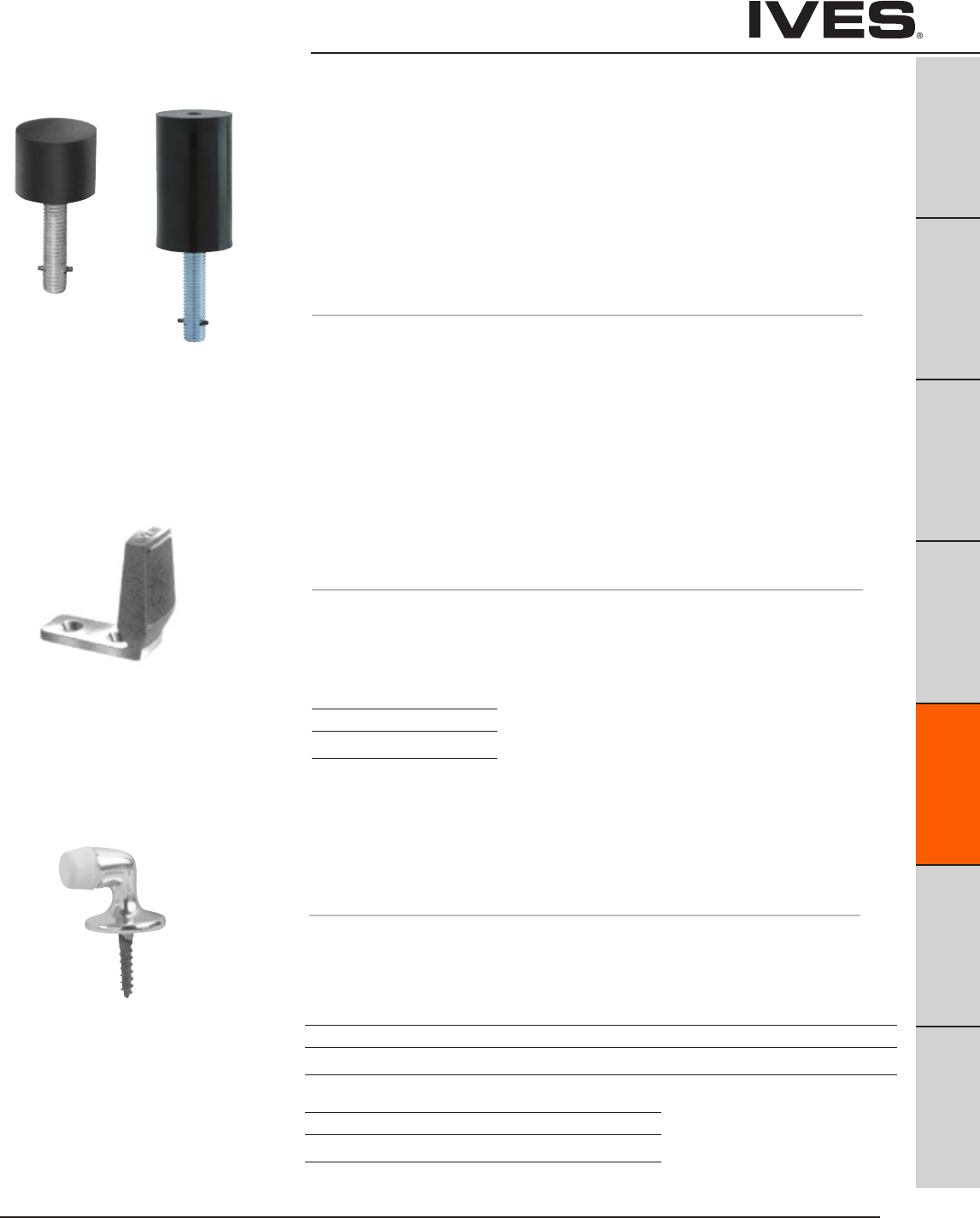
Ives Architectural hardware products E5
Floor Stops
B
Pulls & Plates
A
Hinges & Pivots
C
Flush Bolts & Coordinators
D
Latches, Catches & Bolts
E5
Stops
F
Exterior Hardware
G
Miscellaneous Hardware
FS18S
FS18L Floor Stops
• SecurityDoorStopsdesignedforuseinhighvandalismareas.
• Moldedfromblackflameresistant,resilientmaterialarounda
heavy-duty stud.
• Oncegroutedinconcrete,leavesnoexposedfastenerstobe
tampered with or removed.
• Idealforjailorsecuritycellareaswherefloormountedstopsarerequired.
• FS18Lalsoidealforconcretewallapplications.
Dimensions
FS18S Height: 1-1/2” FS18L Height: 3-1/2”
FS18S Diameter: 2” FS18L Diameter: 2”
FS18S Stud Length: 2-1/2” FS18L Stud Length: 2-1/2”
FS18LFS18S
FS434 Floor Stop
• Burnishedwroughtsteel.
• Forundercutdoorsupto1-1/2”.
• Packedwithscrewsandplasticanchors.
• Replaceablesoft,resilientgrayrubber.
Dimensions
Overall Height: 2-5/8”
Base Size: 1-1/2” W x 2-3/4” L
Finishes
Ives Number USC
BHMA 604
430 Floor Door Stop
• Burnishedwroughtsteel.
• Forundercutdoorsupto1-1/2”.
• Packedwithscrewsandplasticanchors.
• Replaceablesoft,resilientgrayrubber.
Dimensions
Overall Height: 1-5/16”
Base Diameter: 1-1/4”
Finishes brass
Ives Number B3 B4 B5 B10B B15 B26 B26D
BHMA 605 606 609 613 619 625 626
Finishes aluminum
Ives Number A3* A5 A14 A92
BHMA 666 669 673
* only available in Slim-Pak of 25
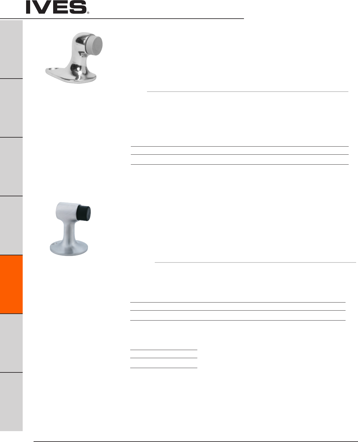
Ives Architectural hardware products
E6
Floor Stops
B
Pulls & Plates
A
Hinges & Pivots
C
Flush Bolts & Coordinators
D
Latches, Catches & Bolts
E6
Stops
F
Exterior Hardware
G
Miscellaneous Hardware
FS441 Floor Stop
• Accommodatesdoorundercutupto1-1/2”.
• Designedtoblendwellwithalltypesofconstructionand
provide a minimum of hindrance to cleaning efforts.
• Heavy-Dutycastbrassoraluminumconstruction.
• ReplaceableNon-marringrubberbumper.
FS441 packed with expansion shield and tampin for masonry type mounting,
and wood screws for drywall mounting.
Dimensions
Overall Height: 2-1/8”
Overall Length: 2-7/8”
Base Depth: 1-5/8”
FS444 Floor Stop
FS448 Floor Stop
• Idealforinteriororexterioruse.
• Castbrassconstruction.
• Accommodatesdoorundercutupto2-1/2”.
• ReplaceableNon-marringrubbertip.
FS444 is packed with expansion shield and lead shield, for masonry type mounting.
FS448 is packed with wood screws, for drywall mounting.
Dimensions
Overall Height: 3”
Base Diameter: 2-1/2”
Finishes brass
Ives Number US3 US4 US5 US10 US10B US15 US26 US26D
BHMA 605 606 609 612 613 619 625 626
Finishes brass
Ives Number US3 US4 US5* US10 US10B US15 US26 US26D
BHMA 605 606 609 612 613 619 625 626
Finishes aluminum
Ives Number US28*
BHMA 628
FS444
Meets ANSI/BHMA 156.16, L12131 for brass
FS448
Meets ANSI/BHMA 156.16,
L12121 for brass and L32121 for aluminum
Meets ANSI/BHMA 156.16, L12131 for brass
* not available on FS444
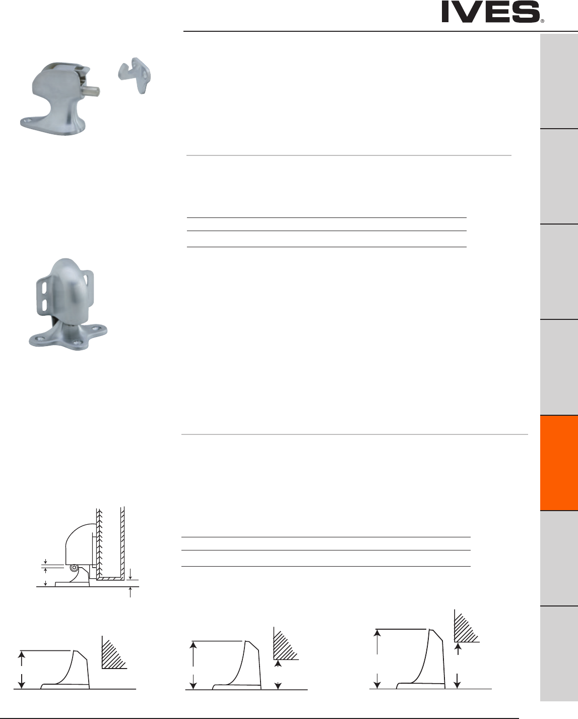
Ives Architectural hardware products E7
Floor Stops
B
Pulls & Plates
A
Hinges & Pivots
C
Flush Bolts & Coordinators
D
Latches, Catches & Bolts
E7
Stops
F
Exterior Hardware
G
Miscellaneous Hardware
FS40 Floor Stop & Automatic Holder
FS41
FS42
FS43
• Automaticdoorholdersidealforheavy-trafficsituationsthatrequire
a simple, fool-proof, Hold-Open device.
• Forgedfrombrass.
• Unitisactivatedautomaticallywhendoorisopened.
A firm pull on door releases the mechanism.
• Strikesaccommodatedifferentdoortofloorclearances.
• Modelnumbersaredeterminedbystrike/door-to-floorclearances.
• Holderpositionondoorisadjustable.
• Universalscrewpackallowsforinstallationinalltypesofdoorconstruction.
Dimensions
Door to Floor Clearance: FS40 1/2” or less
FS41 9/16” to 1-1/16”
FS42 1-1/8” to 1-9/16”
FS43 1-5/8” to 2-1/16”
Holder Dimensions: 3” Wide x 3-11/16” High
1-3/16”
SIDE VIEW BODY
F40 MAX. DOOR
CLEARANCE
1/2”
1/8” CLEARANCE
1-3/4” CLEARANCE
FROM 9/16 to 1-1/16
2-1/4”
2-3/4”
CLEARANCE
FROM 1-1/8 to 1-9/16
CLEARANCE
FROM 1-5/8 to 2-1/16
1-3/4” CLEARANCE
FROM 9/16 to 1-1/16
2-1/4”
2-3/4”
CLEARANCE
FROM 1-1/8 to 1-9/16
CLEARANCE
FROM 1-5/8 to 2-1/16
1-3/4” CLEARANCE
FROM 9/16 to 1-1/16
2-1/4”
2-3/4”
CLEARANCE
FROM 1-1/8 to 1-9/16
CLEARANCE
FROM 1-5/8 to 2-1/16
FS41 FS42 FS43
Meets ANSI/BHMA 156.16, L11301
Finishes brass
Ives Number US3 US4 US10 US10B US26 US26D
BHMA 605 606 612 613 625 626
FS9 Floor Stop & Semi-Automatic Holder
• Semi-automaticfloor-mountedholdersaccommodateswithdoorto
floor clearance of 1-1/2” or less.
• Castfromheavy-dutybrass.
• Activateholderbyflippingtheengagementtongueforward.When
door is opened, the hook (mounted on door) engages the tongue.
To release, push firmly on door to disengage tongue.
• Universalscrewpackaccommodatesalltypesoffloorand
door construction.
Dimensions
Overall Height: 3-1/2
Base Dimensions: 2” wide x 3-1/2” long
Finishes
Ives Number US3 US4 US10 US10B US26 US26D
BHMA 605 606 612 613 625 626
Meets ANSI/BHMA 156.16, L11241.

Ives Architectural hardware products
E8
Floor Stops
B
Pulls & Plates
A
Hinges & Pivots
C
Flush Bolts & Coordinators
D
Latches, Catches & Bolts
E8
Stops
F
Exterior Hardware
G
Miscellaneous Hardware
FS495 Wall Stop & Automatic Holder
FS496 Floor Stop & Automatic Holder
FS497 Floor Stop & Automatic Holder
• Automaticdoorholdersidealforheavy-trafficsituationsthatrequireasimple,
Hold-Open device.
• Castbrassconstruction.
• Recommendedinstallationisholderondoorandstrikeonwall.
• Holderpositionondoorisadjustable.
• Holderistaperedtoprevent“childriding.”
Dimensions
FS495 Holds door 3-3/4” from wall.
FS496 Door to Floor Clearances 3/8” Maximum.
FS497 Door to Floor Clearances 1” Maximum.
FS495 Meets ANSI/BHMA 156.16, L11291 for brass
FS496 Meets ANSI/BHMA 156.16, L11301 for brass
FS497 Meets ANSI/BHMA 156.16, L11301 for brass
Finishes brass
Ives Number US3 US4* US10 US10B US26 US26D
BHMA 605 606 612 613 625 626
* not available on FS496, FS497.
FS495 shown
FS446 Floor Stop & Manual Door Holder
FS450 Floor Stop & Manual Door Holder
• Manualtypefloorholderidealforinteriororexterioruse.
• Castbrassoraluminumconstruction.
• Accommodatesdoorundercutupto2-1/2”.
• Replaceablenon-marringrubbertip.
• UnitfunctionsasastopbutservesasaHold-Opendevicewhen
hook is manually engaged in strike. Unit requires manual
disengagement to release Hold-Open.
FS446 packed with expansion shield and lead shield, for masonry type mounting
FS450 packed with 3 wood screws, for drywall mounting.
Dimensions
Overall Height: 3-3/4
Height from Floor to Stop Center Line: 2-5/8”
Stop Diameter: 1-1/16”
Base Diameter: 2-1/12”
Finishes brass
Ives Number US3 US4 US10 US10B US15 US26 US26D
BHMA 605 606 612 613 619 625 626
Finishes aluminum
Ives Number US28
BHMA 628
FS446
Meets ANSI/BHMA 156.16, L11371 for brass
and L31371 for aluminum.
FS450
Meets ANSI/BHMA 156.16, L11361 for brass
and L31371 for aluminum.
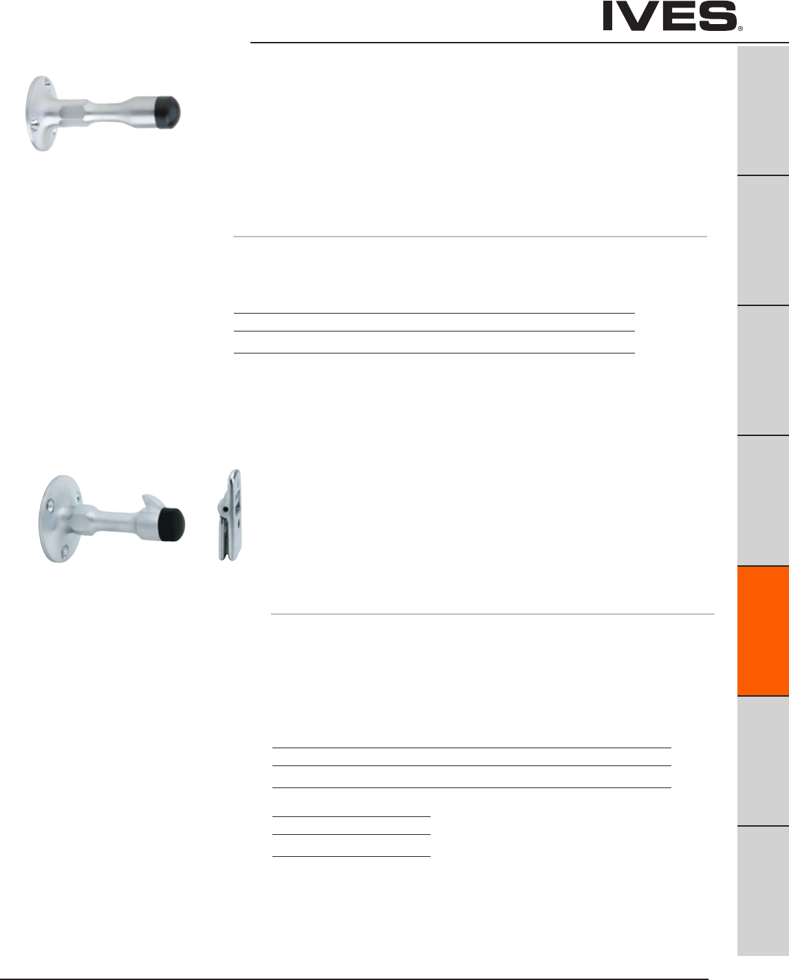
Ives Architectural hardware products E9
Wall Stops
B
Pulls & Plates
A
Hinges & Pivots
C
Flush Bolts & Coordinators
D
Latches, Catches & Bolts
E9
Stops
F
Exterior Hardware
G
Miscellaneous Hardware
WS11
WS11X Wall Stops
• Constructedinheavydutycastbrass.
• Hexagonsectiononunitaidsinfasteningunitwhenexpansionshieldisused.
• Replaceablerubberbumpersfeaturesoff-setshoulderandthreadedshank
that screws into body of unit.
WS11 is furnished with wood screws for drywall mounting.
WS11X is furnished with a threaded stud and expansion shield for
masonry type mounting.
Dimensions
Base Diameter: 2”
Overall Projection: 3-3/4”
Finishes brass
Ives Number US3 US4 US10 US10B US26 US26D
BHMA 605 606 612 613 625 626
WS20
WS20X Manual Wall Holders
• Constructedincastbrassoraluminum.
• Replaceablerubberbumpersfeatureoff-setshoulderandthreaded
shank that screws into body of holder.
• Hingedstrikefurnishedmatchesbodymaterialandfinish.
WS20 is furnished wood screws for drywall mounting.
WS20X is furnished with threaded stud and expansion shield
for masonry type mounting.
Dimensions
Base Diameter: 2-3/8”
Overall Projection: 4”
Strike Height: 2”
Strike Width: 1”
WS20
Meets ANSI/BHMA 156.16, L11341for brass
and L32341 for aluminum
WS20X
Meets ANSI/BHMA 156.16, L11351 for brass
and L31351 for aluminum
Finishes brass
Ives Number US3 US4 US10 US10B US26 US26D
BHMA 605 606 612 613 625 626
Finishes aluminum
Ives Number US28
BHMA 628
WS11
Meets ANSI/BHMA 156.16, L12011
WS11X
Meets ANSI/BHMA 156.16, L12021
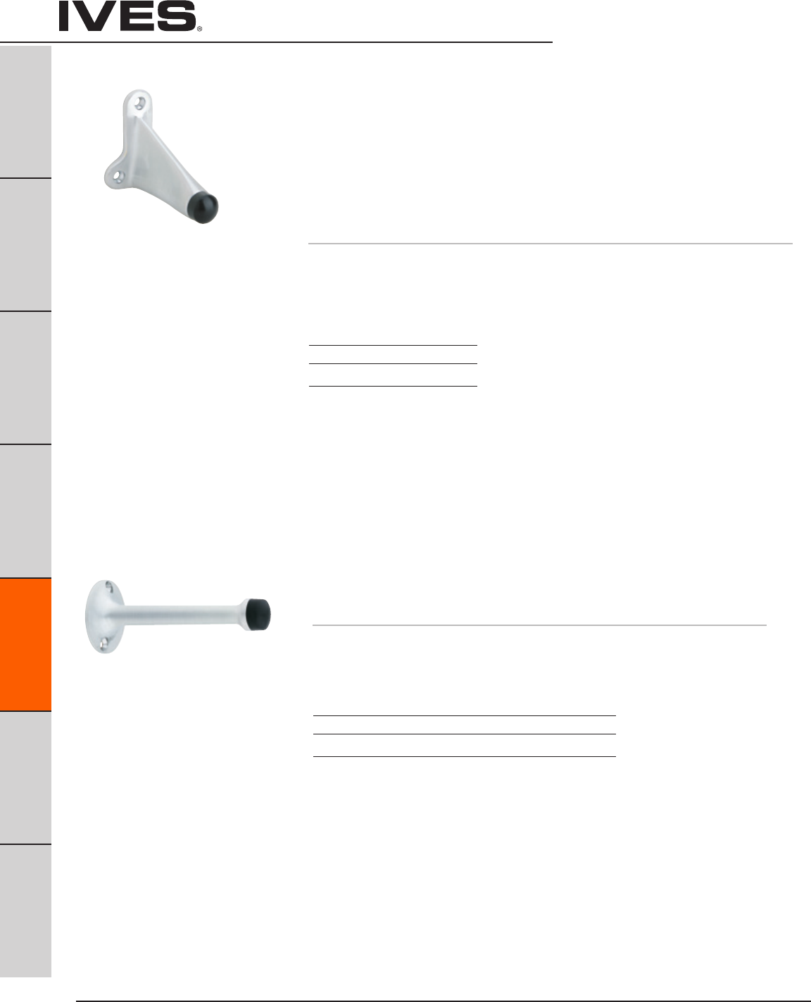
Ives Architectural hardware products
E10
Wall Stops
B
Pulls & Plates
A
Hinges & Pivots
C
Flush Bolts & Coordinators
D
Latches, Catches & Bolts
E10
Stops
F
Exterior Hardware
G
Miscellaneous Hardware
WS33
WS33X Wall Stops
• Constructedinadurablecastbrass.
• Replaceablerubberbumperwithoffsetshoulderscrewsintocavityonbody
to prevent loss or theft.
• Slopingdesigndiscouragesvandalism
WS33 is furnished with wood screws for drywall mounting.
WS33X is furnished with a threaded stud and expansion shield for
masonry type mounting.
Dimensions
Base Diameter: 2-1/4” wide x 3” High
Overall Projection: 3-3/4”
Finishes brass
US Number US26D
BHMA 626
WS33
Meets ANSI/BHMA 156.16, L12011
WS33X
Meets ANSI/BHMA 156.16, L12021
WS65 Wall Stop
• Burnishedcastaluminum.
• Replaceablenon-marringwhiterubberbumper.
• Packedwithsheetmetalscrews.
Dimensions
Base Diameter: 1-5/8”
Overall Projection: 3-3/4”
Finishes aluminum
Ives Number US3 US10 US10B US27
BHMA 666 668 703 673
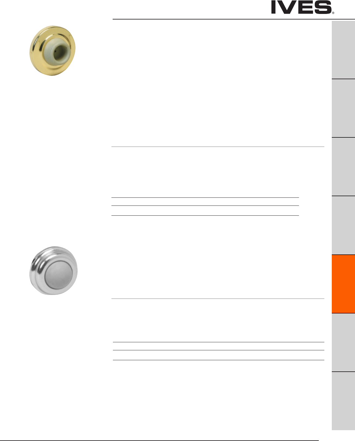
Ives Architectural hardware products E11
Wall Bumpers
B
Pulls & Plates
A
Hinges & Pivots
C
Flush Bolts & Coordinators
D
Latches, Catches & Bolts
E11
Stops
F
Exterior Hardware
G
Miscellaneous Hardware
WS401CVX Wall Bumpers
WS401CCV
WS402CVX
WS402CCV
• Constructedinheavy-dutycastbrass.
• Specialretainercupmakesrubbertamperresistant.
WS401CVX (401) – convex rubber bumper, packed with wood screw
and plastic anchor.
WS401CCV (401-1/2) – concave rubber bumper which avoids damage to locks
with projecting buttons, packed with wood screw and plastic anchor.
WS402CVX (402) – convex rubber bumper packed with screw and drywall anchor.
WS402CCV (402-1/2) – concave rubber bumper which avoids damage to locks
with projecting buttons and is packed with screw and drywall anchor.
Dimensions
Base Diameter: 2-1/2”
Base Thickness: 3/8”
Overall Projection: 1”
WS404CVX Wall Bumpers
•Compactsize.
•Constructedincastbrass.
•Totallyconcealedmountingdiscouragesvandalismortampering.
•Unitfurnishedwithgreyconvexrubberbumper.
•Packedwithsheetmetalscrew,rawlplugandbrad.
Dimensions
Base Diameter: 1”
Overall Projection: 17/32”
WS401CCV & WS402CCV
Meets ANSI/BHMA 156.16 L12251 for brass
WS401CVX & WS402CVX
Meets ANSI/BHMA 156.16 L12101 for brass
Finishes
Ives Number US3 US4 US10 US10B US15 US26 US26D
BHMA 605 606 612 613 619 625 626
Finishes
Ives Number US3 US4 US5 US10 US10B US15 US26 US26D
BHMA 605 606 609 612 613 619 625 626
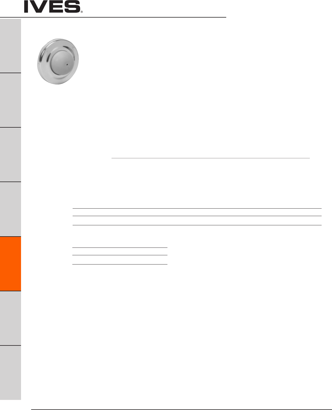
Ives Architectural hardware products
E12
Wall Bumpers
B
Pulls & Plates
A
Hinges & Pivots
C
Flush Bolts & Coordinators
D
Latches, Catches & Bolts
E12
Stops
F
Exterior Hardware
G
Miscellaneous Hardware
WS406CVX & WS407CVX
Meets ANSI/BHMA 156.16 L22201 for brass,
and L52101 for stainless steel.
WS406CCV & WS407CCV
Meets ANSI/BHMA 156.16 L22251 for brass
and and L52251 for stainless steel.
WS406CVX Wall Bumpers
WS406CCV
WS407CVX
WS407CCV
• Constructedinsturdyyeteconomicalwroughtbaseofbrass
or stainless steel construction.
• Featureconcealedtamper-proofmounting.
• Shippedfactorypreassembledbackplatetoreduceinstallationcost.
• Easyinstallationbyinsertingscrewdriverthroughsmallholeinrubber.
WS406CVX (406) – convex rubber bumper, packed with wood screw
and plastic anchor.
WS406CCV (406-1/2) – concave rubber bumper, which avoids damage to locks
with projecting buttons, packed with wood screw and plastic anchor.
WS407CVX (407) – convex rubber bumper packed with screw and drywall anchor.
WS407CCV (407-1/2) – concave rubber bumper which avoids damage to locks with
projecting buttons and is packed with screw and drywall anchor.
Dimensions
Base Diameter: 2-1/2”
Base Thickness: 3/8”
Overall Projection: 1”
Finishes brass
Ives Number US3 US4 US5* US10 US10B US15 US15A** US26 US26D B716**
BHMA 605 606 609* 612 613 619 620 625 626
Finishes stainless steel
Ives Number US32D
BHMA 630
* only available on WS407CVX Slim-Pak of 15
** available on WS407CCV or WS407CVX Slim-Pak of 15

Ives Architectural hardware products E13
Wall Bumpers
B
Pulls & Plates
A
Hinges & Pivots
C
Flush Bolts & Coordinators
D
Latches, Catches & Bolts
E13
Stops
F
Exterior Hardware
G
Miscellaneous Hardware
411R-W Wall Bumper
• Adhesive-backedwalldoorstopforuseonclean,smooth,flatsurfacesonly.
• Non-marringwhiterubber.
• Concavedesignpermitsknobtostrikestopwithoutdamagingor
engaging lock mechanism.
Dimensions
Base Diameter: 1-7/8”
Base Thickness: 3/8”
Overall Projection: 1-1/16”
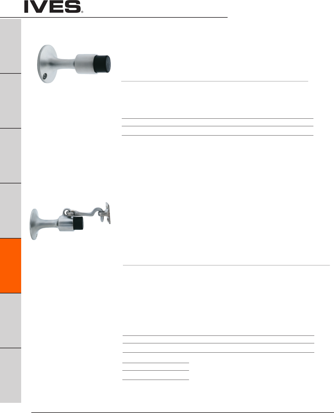
Ives Architectural hardware products
E14
Wall Stops & Holders
B
Pulls & Plates
A
Hinges & Pivots
C
Flush Bolts & Coordinators
D
Latches, Catches & Bolts
E14
Stops
F
Exterior Hardware
G
Miscellaneous Hardware
WS445
WS449 Manual Wall Holder
• Constructedincastofbrassoraluminum.
• UnitfunctionsasastopbutservesasaHold-Opendevicewhenhook
is manually engaged in strike.
• UnitrequiresmanualdisengagementtoreleaseHold-Open.
• Replaceableresilient,non-marringrubbertip.
WS445 is packed with expansion shield and lead shield for masonry type mounting.
WS449 is packed with wood screws for drywall mounting.
Dimensions
Base Diameter: 2-1/4”
Base Projection: 3-11/16”
Engaged Projection: 5-3/4”
Strike Height: 1-1/2”
Strike Width: 13/16”
Strike Projection: 13/16”
Finishes brass
Ives Number US3 US4 US10 US10B US15 US26 US26D
BHMA 605 606 612 613 619 625 626
WS445
Meets ANSI/BHMA 156.16, L11351 for brass.
WS449
Meets ANSI/BHMA 156.16, L11341 for brass
and L31341 for aluminum.
Finishes aluminum
Ives Number US28*
BHMA 628
* only available on WS449
WS443
WS447 Wall Stop
• Constructedinbrass.
• Idealforinteriororexterioruse.
• Replaceablenon-marringrubbertip.
WS443 is packed with expansion shield and lead shield for masonry type mounting.
WS447 is packed with wood screws for drywall mounting.
Dimensions
Base Diameter: 2-1/4”
Overall Projection: 3-11/16”
Finishes brass
Ives Number US3 US4 US10 US10B US15 US26 US26D
BHMA 605 606 612 613 619 625 626
WS443
Meets ANSI/BHMA 156.16, L12021 for brass
and L32021 for aluminum.
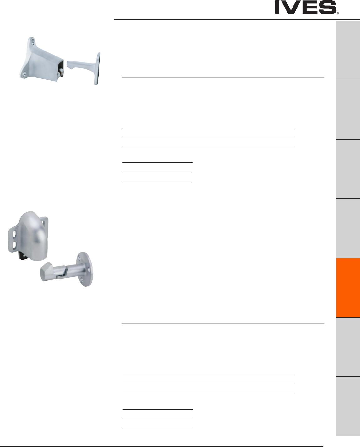
Ives Architectural hardware products E15
Automatic Wall Holders
B
Pulls & Plates
A
Hinges & Pivots
C
Flush Bolts & Coordinators
D
Latches, Catches & Bolts
E15
Stops
F
Exterior Hardware
G
Miscellaneous Hardware
WS40 Automatic Wall Holder
• Constructedofsturdycastbrass,oraluminum.
• Holderismountedonwallandstrikeismountedondoor.
• Rolleronholderridesupseatsitselfonstrike,withaheavydutybumper
pad deadening the sound and shock.
• Universalscrewpackaccommodatesalltypeswallconstruction.
Dimensions
Base Height: 2”
Base Width: 2-1/2”
Base Projection: 2-1/4”
Engaged Projection: 3-1/2”
WS45
WS45X Automatic Wall Holder
• Constructedofcastbrass,bronzeoraluminum.
• Springloadedrollerridesupthefaceofthestrike,
seating itself on the strike, holding the door firmly in the open position.
• Aheavyrubberpadcushionstheshockandabsorbsthesound.
• Withunitmountedondoorandthestrikeonwall,verticaladjustment
is available on body.
• Thestrikeisadjustable45degreesleftorright,bothadjustmentseasily
accomplished at time of installation or at a later date.
WS45 strike is furnished with wood screws for drywall mounting.
WS45X strike is furnished with a threaded stud and expansion shield
for masonry type mounting.
Dimensions
Base Height: 3-11/16” Strike Diameter: 2-3/8
Base Width: 3” Strike Projection: 3”
Base Projection: 2”
Engaged Projection: 3-7/16”
Meets ANSI/BHMA 156.16, L11291 for brass
and L31291 for aluminum.
WS45
Meets ANSI/BHMA 156.16, L11291 for brass
and L31291 for aluminum.
Finishes brass
Ives Number US3 US4 US10 US10B US26 US26D
BHMA 605 606 612 613 625 626
Finishes aluminum
Ives Number US28
BHMA 628
Finishes brass
Ives Number US3 US4 US10 US10B US26 US26D
BHMA 605 606 612 613 625 626
Finishes aluminum
Ives Number US28
BHMA 628
Strike Height: 2-1/16”
Strike Width: 3/4”
Strike Projection: 2”

Ives Architectural hardware products
E16
Kick Down Holders
B
Pulls & Plates
A
Hinges & Pivots
C
Flush Bolts & Coordinators
D
Latches, Catches & Bolts
E16
Stops
F
Exterior Hardware
G
Miscellaneous Hardware
FS452 Kick Down Holder
• Unitsprovidesimpleholdandrelease,activatedwithatouchofthefoot.
• Castbrassoraluminumconstruction.
• Stainlesssteelspring.
• Replaceablenon-marringrubbershoeshavecorrugatedbottomstoprovide
secure grip.
• Shoesareeasilyreplacedwhenworn.Shoeheldonwithscrew.
• Packedwithsheetmetalscrews.
FS452-4 has a door-to-floor clearance of 2” or less.
FS452-5 has a door-to-floor clearance up to 3”.
Dimensions
FS452-4 Door-to-Floor Clearance: 2” or less FS452-5 Door-to-Floor Clearance: Up to 3”
FS452-4 Plate Height: 2-1/8” FS452-5 Plate Height: 2-1/8”
FS452-4 Plate Width: 1” FS452-5 Plate Width: 1”
FS455 Kick Down Holder
• Unitsprovidesimpleholdandrelease,activatedwithatouchofthefoot.
• Castbrassoraluminumconstruction.
• Replaceablenon-marringrubbershoeshavecorrugatedbottomstoprovide
secure grip. When worn, shoes are easily replaced. Shoe held on with screws.
• Door-to-floorclearancesof2”orless.
Dimensions
Door-to-Floor Clearance: 2” or less
Plate Height: 1-3/4”
Plate Width: 1-3/4”
Meets ANSI/BHMA 156.16, L11383 for brass
and L31383 for aluminum.
Meets ANSI/BHMA 156.16, L11382 for brass
and L31382 for aluminum.
Finishes brass
Ives Number US3 US4 US10 US10B US15 US26 US26D
BHMA 605 606 612 613 619 625 626
Finishes aluminum
Ives Number US28*
BHMA 628
* available in 4” only
Finishes brass
Ives Number US3 US4 US5 US10 US10B US15 US26 US26D
BHMA 605 606 609 612 613 619 625 626
Finishes aluminum
Ives Number US3AL US5AL US10AL US27
BHMA 666 609 668 673

Ives Architectural hardware products E17
Kick Down Holders
B
Pulls & Plates
A
Hinges & Pivots
C
Flush Bolts & Coordinators
D
Latches, Catches & Bolts
E17
Stops
F
Exterior Hardware
G
Miscellaneous Hardware
FS544
FS555 Kick Down Holder
• Unitsprovideaneconomicalmethodtoholdopendoors.
• Castofdurableiron.
• Non-marringrubbershoeshavecorrugatedbottomstoprovidesecuregrip.
Rubber shoe is securely fastened with screw. When worn, shoes are easily
replaced.
FS544 for door-to-floor clearances of 2” or less
FS555 for door-to-floor clearances up to 3”.
Dimensions
FS544
Door-to-Floor Clearance: 2” or less
Plate Height: 2-1/4”
Plate Width: 1-7/16”
FS544
Meets ANSI/BHMA 156.16, L11381
FS555
Meets ANSI/BHMA 156.16, L11391
Finishes
Ives Number SP4 SP10 SP28 SP313 SPBLK
BHMA 706 691 689 695 622
FS555
Door-to-Floor Clearance: Up to 3”
Plate Height: 2-1/4”
Plate Width: 1-7/16”

Ives Architectural hardware products
E18
Plunger Type
Door Holders
B
Pulls & Plates
A
Hinges & Pivots
C
Flush Bolts & Coordinators
D
Latches, Catches & Bolts
E18
Stops
F
Exterior Hardware
G
Miscellaneous Hardware
FS1153 Plunger Type Door Holder
• ProvidesacontemporaryyeteconomicalmethodofpositiveHold-Open.
• Constructedinsturdycastaluminum.
• Springoperatedplungeractivateswithminimalpressure,releasinginstantly
with a light tap on the plat-form lever.
• Providesa1-5/8”throwforalltypesofdoors.
• Ribbednon-marringrubbershoeissecurelyfastenedtounitwithascrew
and is easily replaced when worn.
Dimensions
Height: 6-1/4”
Width: 1-1/2”
Depth: 1-7/16”
Meets ANSI/BHMA 156.16, L31401.
Finishes
Ives Number US28
BHMA 628
FS1154 Plunger Type Door Holder
• Constructedfromheavy-dutycastbrassorbronze.
• Plungerandinternalpartsareplatedsteelandprovidesa1-1/4”throwfor
all types of doors.
• Plungeriseasilyactivatedwithminimalpressure,releasinginstantlywitha
light tap on the platform lever.
• Roundnon-marringrubbershoeissecurelyfastenedwithascrewinflanged
cup to prevent movement or loss. When worn, shoes are easily replaced.
Dimensions
Height: 5-1/2”
Width: 2”
Depth: 1-1/4”
Meets ANSI/BHMA 156.16, L11401.
Finishes
Ives Number US3 US4 US10 US10B US26 US26D
BHMA 605 606 612 613 625 626
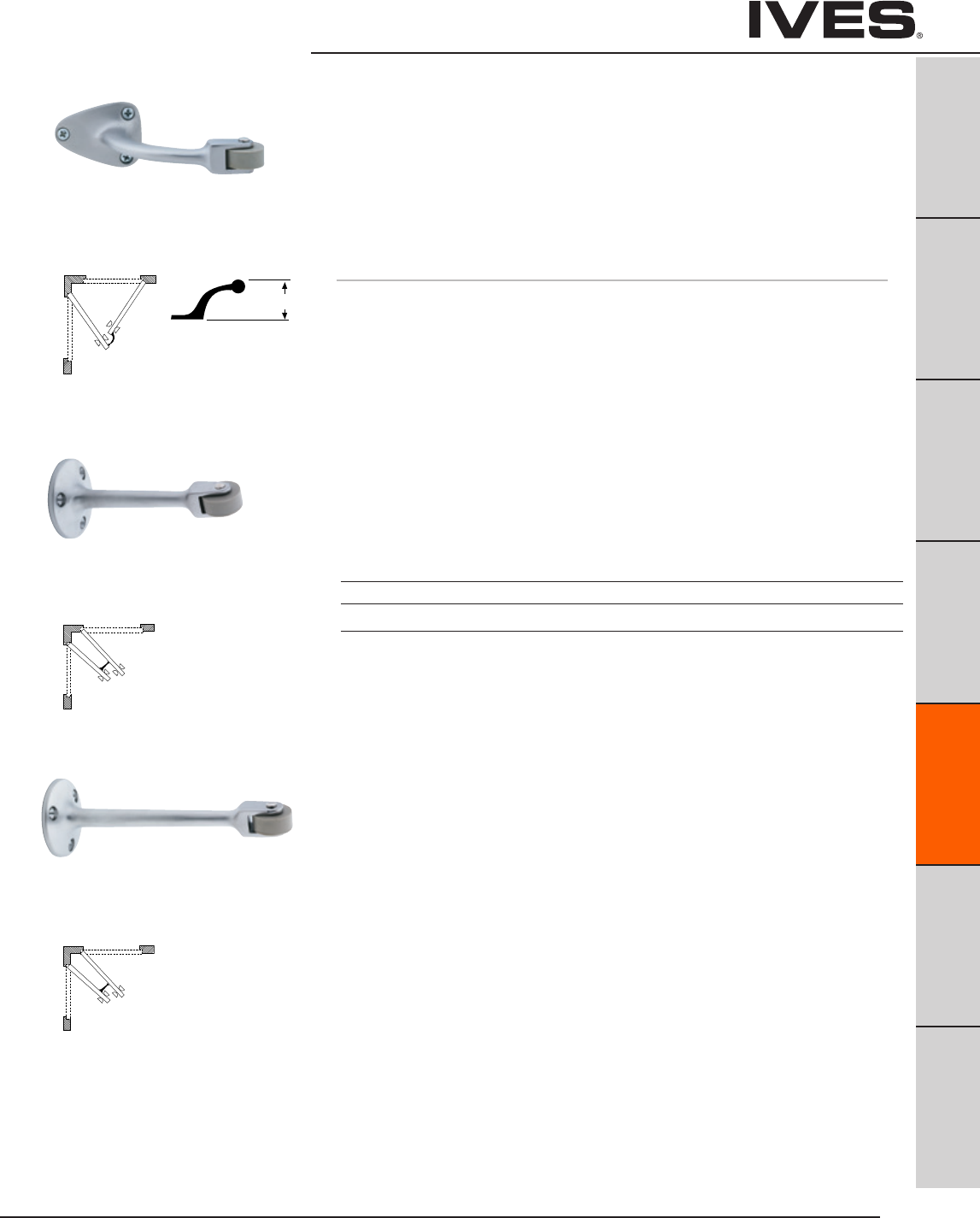
Ives Architectural hardware products E19
Roller Bumpers
B
Pulls & Plates
A
Hinges & Pivots
C
Flush Bolts & Coordinators
D
Latches, Catches & Bolts
E19
Stops
F
Exterior Hardware
G
Miscellaneous Hardware
RB470
RB471
RB472 Roller Bumpers
• Constructedinheavy-dutycastbrass.
• RB470usedwheretwodoorsopenagainsteachotherto
prevent damage to the doors or hardware.
• RB471andRB472areidealforuseinsituationswheredoors
meet each other at approximate right angles (back to back).
• Replaceablerubberrolleravailable.
Dimensions
RB470 Base Size: 1-11/16” x 2-1/4”
RB470 Arm Offset: 2-3/4”
RB470 Length: 5”
RB471 Base Diameter: 2”
RB471 Length: 4-1/2”
RB472 Base Diameter: 2”
RB472 Length: 6”
FS470
FS471
FS472
A
B
A
A
A
B
A
A
A
B
A
A
Offset
Finishes
Ives Number US3 US4** US10* US10B* US15* US26 US26D
BHMA 605 606** 612* 613* 619* 625 626
Meets ANSI/BHMA 156.16, L12212
Meets ANSI/BHMA 156.16, L12192
Meets ANSI/BHMA 156.16, L12202
* only available on RB472
** only available on RB471 and RB472

Ives Architectural hardware products
E20
Residential Door Stops
B
Pulls & Plates
A
Hinges & Pivots
C
Flush Bolts & Coordinators
D
Latches, Catches & Bolts
E20
Stops
F
Exterior Hardware
G
Miscellaneous Hardware
060 Flexible Door Stops
061
• Utilizesheavygaugespringtomaintainrigidprotections
• Simpletoinstall-onlyascrewdriverrequired
• Madefromburnishedwroughtsteel
• Packeddisassembledforquickinstallation
Replaceable white rubber tip available
Dimensions
Base Diameter: 1”
Tip Diameter: 19/16”
060 3” Projection
061 4” Projection
60 Base Door Stops
61
• Availableinthreesizestoaccommodatevaryingareasofinstallation
and door trim dimensions
• Madefromsolidbrassoraluminum
• 61alsoavailableinepoxycoloredaluminum
Replaceable white/black rubber tip available
Dimensions
60 3-3/4” Projection, Base Diameter: 1”
61 3-1/8” Projection on brass units, 3-3/16” Projection on aluminum units,
Base Diameter: 7/8”, Tip Diameter: 5/8”
Finishes steel
Ives Finish F3 F5 F10 F10B F14 F15* F26D F-W**
BHMA 632 638 639 640 645 646 652
Finishes brass
Ives Finish B3 B4 B5 B10 B10B B15 B15A* B26 B26D B716**
BHMA 605 606 609 612 613 619 620 625 626
Finishes aluminum
Ives Finish A3 A5* A10* A10B A14 A15* A19* A92 A716* A-BLK A-W*
BHMA 666 668 703 669 670 A19 673
Finishes zinc
Ives Finish Z605* Z619* Z716*
BHMA
Meets ANSI/BHMA A156.16
* only available on 060
** only available on 061
* only available on 61
** only available on 61 Schlage Carded or slim package of 15
Note: 61A - 716 ships with black rubber tips

Ives Architectural hardware products E21
Residential Door Stops
B
Pulls & Plates
A
Hinges & Pivots
C
Flush Bolts & Coordinators
D
Latches, Catches & Bolts
E21
Stops
F
Exterior Hardware
G
Miscellaneous Hardware
64 Base Door Stop
• BaseDoorStopfeaturesdeluxeone-piecestyling
• Easilyscrewsintobase
• Designedwithsquareheadtoaccommodatewrenchorplierswheninstalling
• Madefromsolidbrassoraluminum
Replaceable white rubber tip available
Dimensions
Base Diameter: 1”
Tip Diameter: 9/16”
Projection: 3-1/4”
69 Hinge Pin Door Stops
• Foruseonhingeddoorswheretheinstallationofastandarddoor
stop is not desirable
• Positiveslipproofadjustment
• Non-marringrubbertips
• Removablebushingsaccommodate1/4”to5/16”diameterhingepins
• Easyinstallation—onlyascrewdriverrequired
• Madefromburnishedwroughtsteel
Replaceable white rubber tip available
Door Opening
70°to100°DoorOpeningAdjustments
Finishes brass
Ives Finish B3 B4 B5 B10 B10B B15 B26 B26D
BHMA 605 606 609 612 613 619 625 626
Finishes aluminum
Ives Finish A3 A10B A92
BHMA 666 703 673
Finishes steel
Ives Finish F3 F5 F10 F10B F14 F15 F15A F26 F26D
BHMA 632 638 639 640 645 646 647 651 652
63 Flexible Door Stops
• Utilizesheavygaugespringtomaintainrigidprotections
• Simpletoinstall-onlyascrewdriverrequired
• Madefromburnishedwroughtsteel
• Packeddisassembledforquickinstallation
Replaceable white rubber tip available
Dimensions
Base Diameter: 1”
Tip Diameter: 9/16”
Projection: 3”
Finishes steel
Ives Finish F605E F609E F619E F716 F-W
BHMA 632 638 646

Ives Architectural hardware products
E22
Residential Door Stops
B
Pulls & Plates
A
Hinges & Pivots
C
Flush Bolts & Coordinators
D
Latches, Catches & Bolts
E22
Stops
F
Exterior Hardware
G
Miscellaneous Hardware
Finishes zinc
Ives Finish Z605E Z609E Z613E Z619E Z625E Z-W
BHMA
Finishes zinc
Ives Finish Z605E Z613E Z619E Z625E
BHMA
Meets ANSI/BHMA 156.6, L12141 for brass
or bronze and L32141 for aluminum.
72 Hinge Pin Door Stops
• Foruseonhingeddoorswheretheinstallationofastandarddoorstop
is not desirable
• Designedfornarrowtriminstallation
• Highqualityrubberbumpers-shoulderonstudsupportsrubberthrough
entire body for engineered cushioning
• Removablebushingsaccommodate1/4”to5/16”diameterhingepins
• Easyinstallation
• Madefromsolidbrass,aluminum,orepoxycoatedaluminum
Door Opening
85°to125°DoorOpeningAdjustments
73 Hinge Pin Door Stops
• Foruseonhingeddoorswheretheinstallationofastandarddoorstop
is not desirable
• Designedfornarrowtriminstallation
• Highqualityrubberbumpers-shoulderonstudsupportsrubberthrough
entire body for engineered cushioning
• Removablebushingsaccommodate1/4”to5/16”diameterhingepins
• Easyinstallation
• Madefromsolidbrass,aluminum,orepoxycoatedaluminum
Door Opening
85°to125°DoorOpeningAdjustments
Door Saver
Door Saver
70 Hinge Pin Door Stops
• Foruseonhingeddoorswheretheinstallationofastandarddoorstop
is not desirable
• Designedfornarrowtriminstallation
• Highqualityrubberbumpers-shoulderonstudsupportsrubberthrough
entire body for engineered cushioning
• Removablebushingsaccommodate1/4”to5/16”diameterhingepins
• Easyinstallation
• Madefromsolidbrass,aluminum,orepoxycoatedaluminum
Replaceable white/black rubber tip available
Door Opening
85°to125°DoorOpeningAdjustments
Finishes brass
Ives Finish B3 B4 B5 B10 B10B B15 B15A* B19 B26 B26D B716*
BHMA 605 606 609 612 613 619 620 622 625 626
Finishes aluminum
Ives Finish A3 A4 A5 A10 A10B A14 A15 A92 A716 A-W A-BLK
BHMA 666 667 668 716 669 670 673
Finishes zinc
Ives Finish Z605E Z406E** Z619E** Z716E
BHMA
* only available in Schlage Carded or Slim-Pak of 25
** only available in Schlage Carded
Note: 70A - 716 ships with black rubber tips
70-Zinc

Ives Architectural hardware products E23
Door Silencers
B
Pulls & Plates
A
Hinges & Pivots
C
Flush Bolts & Coordinators
D
Latches, Catches & Bolts
E23
Stops
F
Exterior Hardware
G
Miscellaneous Hardware
SR64 Door Silencer
• Foruseonmetalframesfeaturingpneumaticdesignthat,onceinstalled,
forms an air pocket to absorb shock and reduce noise of door closing.
• Tamper-proofonceinstalledontheframe.
• Properinstallationalsoeliminatesdoorrattleandprovidesconstant
tension for door latches or locks.
Packed in bags of 100.
Grey Available in bulk pack of 2500.
Each bag has an installation tool included.
Dimensions
Diameter: 1/2”
Thickness: 1/8”
Finishes
GRY, TAN
SR65 Door Silencer
• Foruseonwoodframes,alsofeaturepneumaticdesigntocushionshock
and absorb noise.
• Topreventremoval,asmallbradshouldbedrivenintostopstrip
and through stem of silencer, as shown in the detail.
Packed in bags of 100.
Dimensions
Height: 3/4”
Diameter: 3/8”
Thickness: 1/8”
Finishes
GRY
SR66 Door Silencer
• SelfAdhesiveRubberSilencers.
• Economicalinstallationrequiresnodrillingofframes.
Packed two sheets of 50 (100 minimum).
Dimensions
Diameter: 1/2”
Thickness: 1/8”
Finishes
BRN, GRY, WHT
Meets ANSI/BHMA 156.16, L03011.
Meets ANSI/BHMA 156.16, L03021

Ives Architectural hardware products
E24
Notes
B
Pulls & Plates
A
Hinges & Pivots
C
Flush Bolts & Coordinators
D
Latches, Catches & Bolts
E24
Stops
F
Exterior Hardware
G
Miscellaneous Hardware
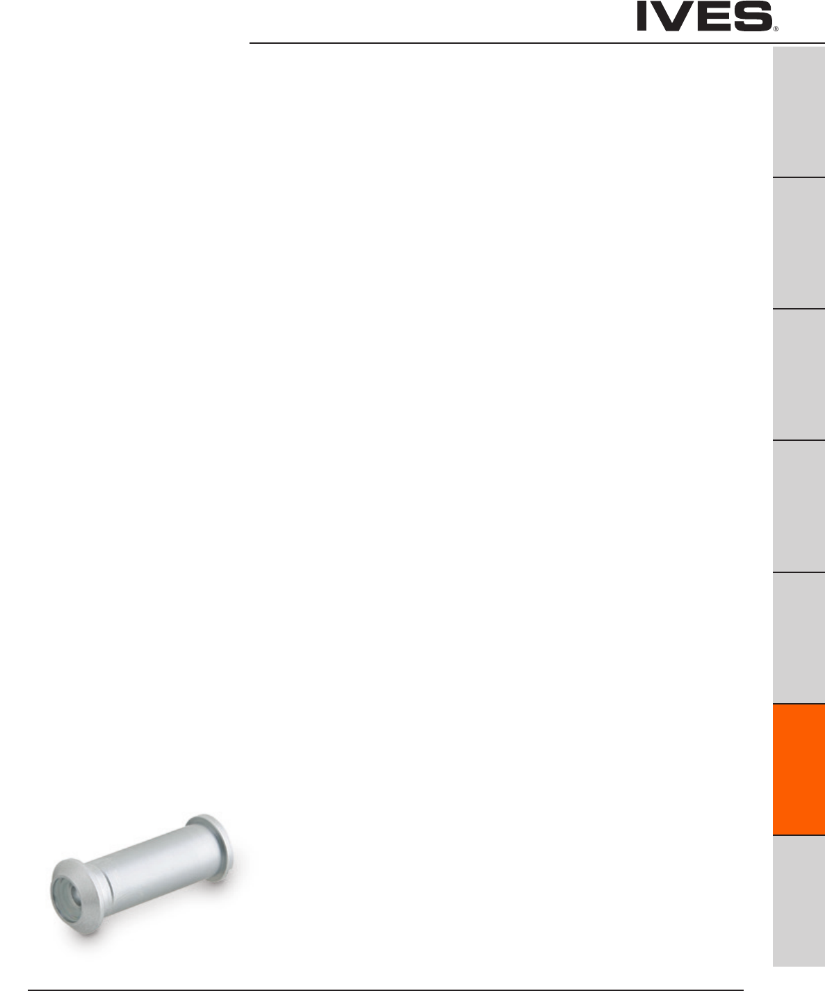
Ives Architectural hardware products F1
Exterior Hardware
B
Pulls & Plates
A
Hinges & Pivots
C
Flush Bolts & Coordinators
D
Latches, Catches & Bolts
E
Stops
F1
Exterior Hardware
G
Miscellaneous Hardware
Table Of Contents
Lock Guards page
LG1, LG7 Lock Guard ...................................................F2
LG10 Lock Guard .......................................................F2
LG11 Lock Guard .......................................................F3
LG12 Lock Guard .......................................................F3
LG13 Lock Guard .......................................................F4
LG14 Lock Guard .......................................................F4
Viewers
U696 One-way Viewer ................................................F5
698, U698 One-way Viewer ...........................................F5
700, U700 One-way Viewer ...........................................F6
701, U701 One-way Viewer .............................................F6
Door Knockers
3107 Door Knocker .....................................................F7
3125 Door Knocker .....................................................F7
Letter Box
620 Letter Box Plate ..................................................F8
601 Letter Box Sleeve .................................................F8
Door Numbers
02-30 Door Numbers ..................................................F9
Storm and Screen Door
980 Storm Door Latch .................................................F9
25 Screen Door Pull ...................................................F10
Crash Stop
CS115 Crash Stop .....................................................F10

Ives Architectural hardware products
F2
Lock Guards
B
Pulls & Plates
A
Hinges & Pivots
C
Flush Bolts & Coordinators
D
Latches, Catches & Bolts
E
Stops
F2
Exterior Hardware
G
Miscellaneous Hardware
LG1 Lock Guard
LG7 • Unitsarenon-handedandincorporatesecurityframepinto
prevent separation of the door and frame. LG7 does not incorporate the
security frame pin
• Unitcoversthelatchboltareaofthedoorandlock,therebyproviding
added protection from burglars, vandals or normal abuse.
• Idealforusewithmortiseorcylindricallocks.
• Easyinstallation.
• Throughboltedwithcarriageboltsandnuts.
• Availableinavarietyofmaterials,13gaugestainlesssteel,
12 gauge steel and brass material.
Dimensions
3" Wide x 11-1/2" High
Bolt center to center: 10-1/2"
LG10 Lock Guard
• Ideallysuitedforusewithroseorescutcheon2-3/4"wideorless.
• ForusewithType86MortiseandType161CylindricalLocks
(ANSI 156.13 Series 1000 and ANSI 156.2 Series 4000).
• Noexposedfastenersonfaceofunit.
• Uniquedesignprovidesmaximumsecurity,virtuallyeliminatingthe
opening between door and frame at the latch point.
• Availablein13GaugeStainlessSteelor12GaugeSteel.
Dimensions
2-1/2" Wide x 9-1/2" High
Stud center to center: 8-1/2"
Finishes
Ives Number USP* US2G* US4* US10* US32D SP313*
BHMA 600 603 606 612 630 695
* not available on LP7
Finishes
Ives Number USP US32D
BHMA 600 630

Ives Architectural hardware products F3
Lock Guards
B
Pulls & Plates
A
Hinges & Pivots
C
Flush Bolts & Coordinators
D
Latches, Catches & Bolts
E
Stops
F3
Exterior Hardware
G
Miscellaneous Hardware
LG11 Lock Guard
• Designedforuseonaluminumdoorswithlatch-typelocks
or doors equipped with electric strikes.
• UnitisHanded-Specifyleftorrighthandwhenordering.
• Noexposedfastenersonfaceofunit.
• Uniquedesignprovidesmaximumsecurity,virtuallyeliminatingthe
opening between door and frame at latch point.
• Availablein13GaugeStainlessSteelor12GaugeSteel.
Dimensions
2-1/2" Wide x 9-1/2" High
Stud center to center: 8-1/2"
LG12 Lock Guard
• Narrowdesignunitforuseonroseorescutcheon3-1/2"orless.
• ForusewithType86MortiseandType161CylinderLocks
(ANSI 156.13 Series 1000 and ANSI 156.2 Series 4000).
• Noexposedfastenersonfaceofunit.
• Uniquedesignprovidesmaximumsecurity,virtuallyeliminatingtheopening
between door and frame at the latch point.
• Availablein13GaugeStainlessSteelor12GaugeSteel
Dimensions
1-1/2" Wide x 9-1/2" High
Stud center to center: 8-1/2”
Finishes
Ives Number US32D SP313
BHMA 630 695
Finishes
Ives Number USP US32D
BHMA 600 630

Ives Architectural hardware products
F4
Lock Guards
B
Pulls & Plates
A
Hinges & Pivots
C
Flush Bolts & Coordinators
D
Latches, Catches & Bolts
E
Stops
F4
Exterior Hardware
G
Miscellaneous Hardware
LG14 Lock Guard
• Narrowdesignunitforuseonroseorescutcheon3-1/2"orless.
• ForusewithVonDuprin6210and6211electricstrike.
• Noexposedfastenersonfaceofunit.
• Uniquedesignprovidesmaximumsecurity.
• Availablein13GaugeStainlessSteel
Dimensions
2-9/16" Wide x 9-1/2" High
Stud center to center: 8-1/2"
LG13 Lock Guard
• DesignedforuseonallType161CylindricalLocks(ANSI156.2Series2000)
Monolock and Unilock.
• Noexposedfastenersonfaceofunit.
• Uniquedesignprovidesmaximumsecurity,virtuallyeliminatingthe
opening between door and frame at latch point.
• Availablein13GaugeStainlessSteelor12GaugeSteel.
Dimensions
1-1/2" Wide x 7" High
Stud center to center: 4-1/2"
Finishes
Ives Number USP US32D
BHMA 600 630
Finishes
Ives Number US32D
BHMA 630
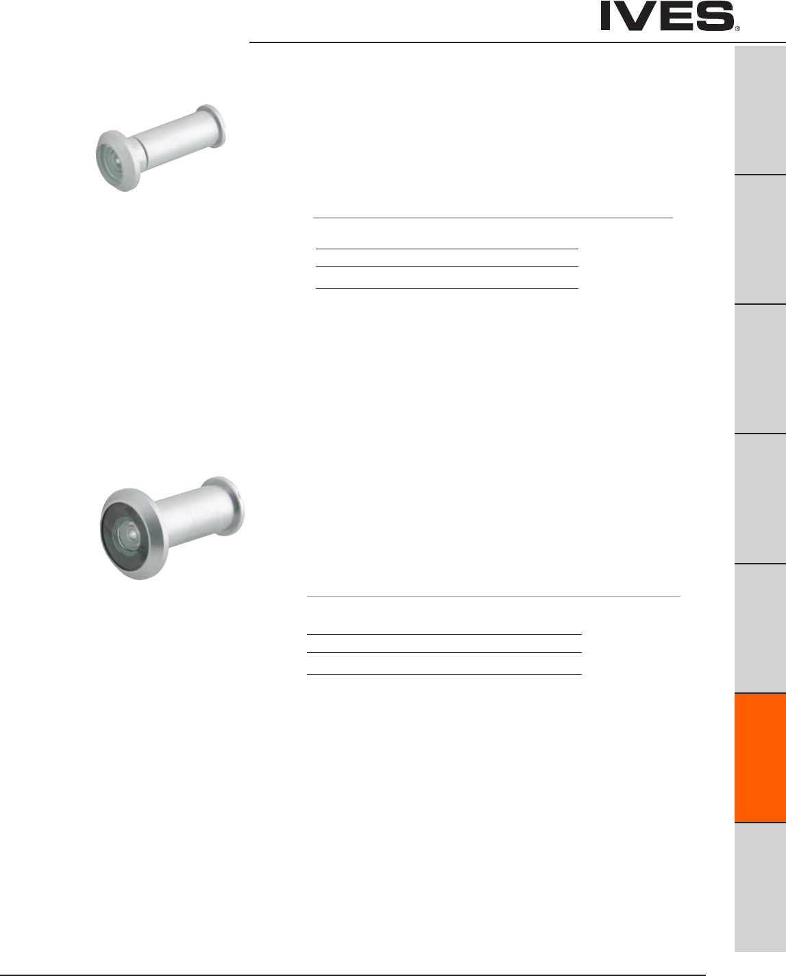
Ives Architectural hardware products F5
Viewers
B
Pulls & Plates
A
Hinges & Pivots
C
Flush Bolts & Coordinators
D
Latches, Catches & Bolts
E
Stops
F5
Exterior Hardware
G
Miscellaneous Hardware
U696 One-Way Viewer
• 150°AngleofView.
• Fordoors1-3/8"to2-1/16"thick.
• Secure,tamper-resistant.
• Solidbrassbody;glasslens.
• Simpleinstallation—onlya1/2"holerequired.
• Suggestedinstallationheight:60"fromfloor.
• Trimwasheravailable,3/4"x.032"thick.
698
U698 One-Way Wide Angle Viewer
• 190°AngleofView.
• Lensprojects1/4"fromfaceofdoor.
• 4opticalglasslenses.
• Fordoors1-3/8"to2-1/8"thick.
• Solidbrassbodyandbarrel.
• Simpleinstallation—onlya9/16"holerequired.
• Suggestedinstallationheight:60"fromfloor.
Meets ANSI/BHMA A156.16 L23222
UL Listed 90 minute fire doors
Finishes
Ives Number B4 B10B B26D
BHMA 606 613 626
Finishes
Ives Number B3 B15** B26D B716*
BHMA 605 619 626
* not available on U698
** only available in Schlage Carded
698 meets ANSI/BHMA A156.16 L23172
U698 meets ANSI/BHMA A156.16 L23222
U698 is UL Listed 90 minute fire doors
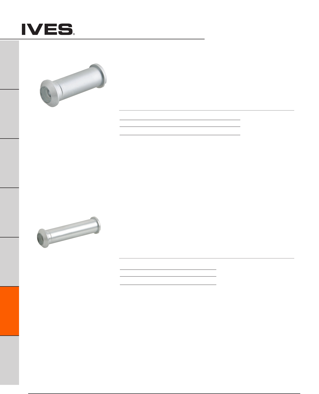
Ives Architectural hardware products
F6
Viewers
B
Pulls & Plates
A
Hinges & Pivots
C
Flush Bolts & Coordinators
D
Latches, Catches & Bolts
E
Stops
F6
Exterior Hardware
G
Miscellaneous Hardware
700
U700 One-Way Viewer
• 120°AngleofView.
• Fordoors1-3/8"to2-1/16"thick.
• Secure,tamper-resistant.
• Solidbrassbody;glasslens.
• Simpleinstallation—onlya1/2"holerequired.
• Suggestedinstallationheight:60"fromfloor.
• Trimwasheravailable,3/4"x.032"thick.
701
U701 One-Way Viewer
• 120°AngleofView.
• Fordoors2-1/8"to2-5/8"thick.
• Secure,tamper-resistant.
• Solidbrassbody;glasslens.
• Simpleinstallation—onlya1/2"holerequired.
• Suggestedinstallationheight:60"fromfloor.
• Trimwasheravailable,3/4"x.032"thick.
700 meets ANSI/BHMA A156.16 L23173
U700 meets ANSI/BHMA A156.16 L23222
U700 is UL Listed 90 minute fire doors
701 meets ANSI/BHMA A156.16 L23173
U701 meets ANSI/BHMA A156.16 L23222
U701 is UL Listed 90 minute fire doors.
Finishes
Ives Number B3** B4 B10B* B26D
BHMA 605 606 613 626
* not available on U700
** only available on 700 in Schlage Carded
Finishes
Ives Number B4 B10B B26D
BHMA 606 613 626
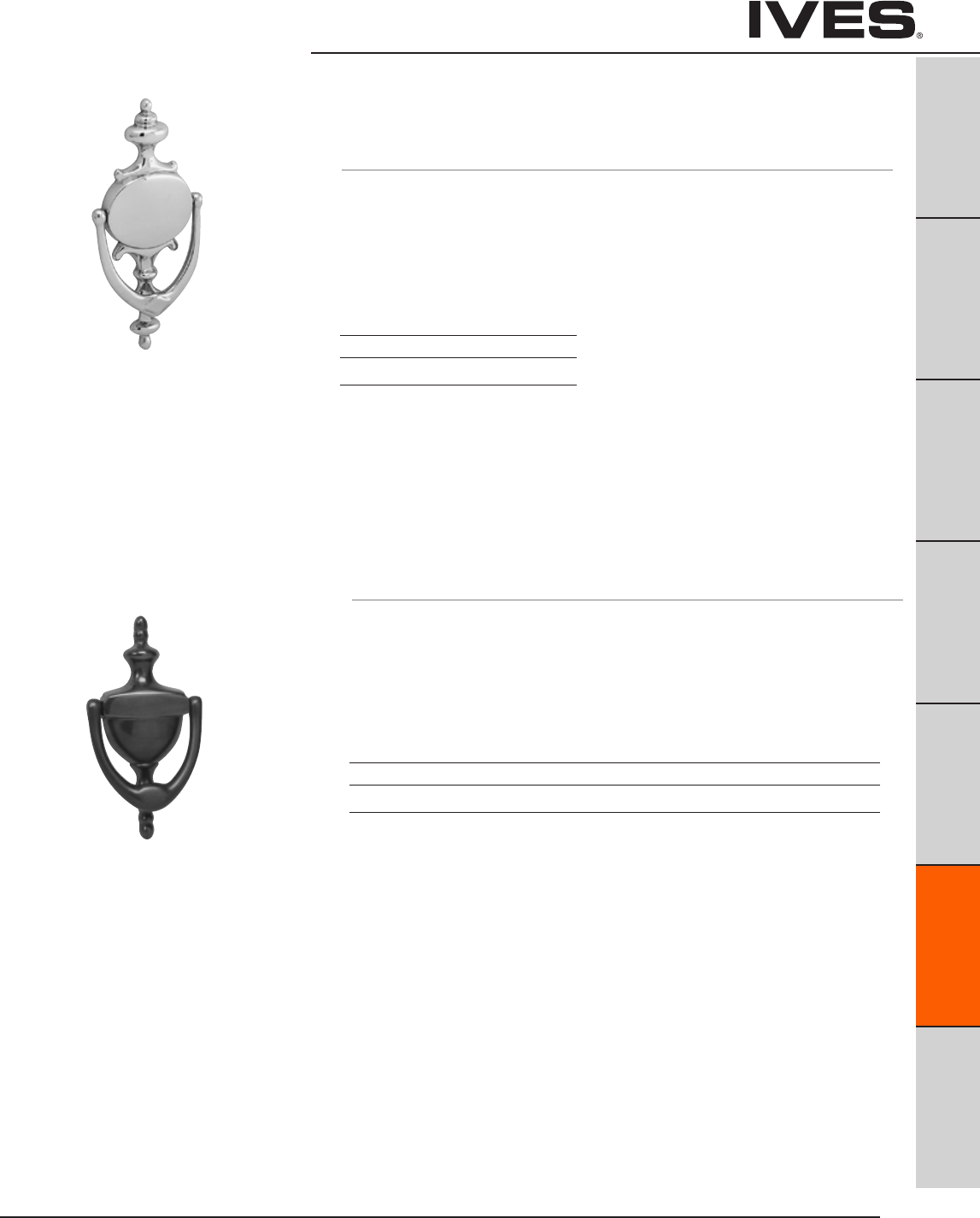
Ives Architectural hardware products F7
Door Knockers
B
Pulls & Plates
A
Hinges & Pivots
C
Flush Bolts & Coordinators
D
Latches, Catches & Bolts
E
Stops
F7
Exterior Hardware
G
Miscellaneous Hardware
02-3125 Knocker Only
02-31251U Knocker with U700 Viewer
02-31252U Knocker with U701 Viewer
• Knockermadefromforgedbrass.
• 02-31251and02-31251Ufordoorthickness7/8"–1-9/16"
• 02-31252and02-31252Ufordoorthickness1-5/8"–2-1/8"
Dimensions
Length: 5-15/16"
Width: 3"
Projection: 1-1/16"
Mounting Hole Center-to-Center: 3-15/16"
Meets ANSI/BHMA A156.16 L23161
Finishes
Ives Number B3 B5 B15 B15A* B26 B26D 716
BHMA 605 609 619 620 625 626
* not available on viewer, only available in Schlage Carded
Only B3, B15, B26D and 716 knockers are available with viewer. B3 is furnished with B4
(606) viewer, 716 is furnished with B10B viewer, B15 (619) is furnished with a 636 viewer.
Meets ANSI/BHMA A156.16 L23151
02-3107 Knocker Only
• Knockermadefromforgedbrass.
• OnlyavailableinSchlageCardedpak
Dimensions
Length: 8-1/2"
Width: 4-1/8"
Projection: 1"
Mounting Hole Center-to-Center: 5"
Finishes
Ives Number B605 B19
BHMA 605 619
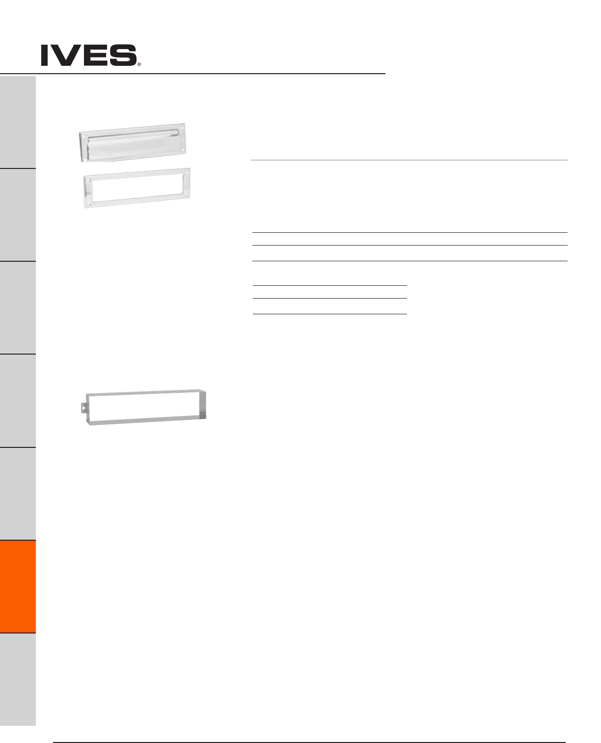
Ives Architectural hardware products
F8
Door Knockers
B
Pulls & Plates
A
Hinges & Pivots
C
Flush Bolts & Coordinators
D
Latches, Catches & Bolts
E
Stops
F8
Exterior Hardware
G
Miscellaneous Hardware
Finishes brass
Ives Number B3 B5 B15 B15A* B26 B26D B716
BHMA 605 609 619 620 625 626
Finishes aluminum
Ives Number PA28
BHMA 628
* not available in U700 Schlage Carded
620 Magazine Size Letter Box Plate with
Standard (Open) Back Plate
• Spring-loadedfrontplate
• SexBoltmountingavailable,orderseparately09-355–finish.
Dimensions
Overall Size: 13" Wide x 3-9/16" High
Plate Opening: 11" x 2" High
601 Sleeve for use with Letter Box Plate
• Madeofstainlesssteel.
• For1-3/4"hollowcoredoors.
Meets ANSI/BHMA A156.16 L26031

Ives Architectural hardware products F9
House Numbers
B
Pulls & Plates
A
Hinges & Pivots
C
Flush Bolts & Coordinators
D
Latches, Catches & Bolts
E
Stops
F9
Exterior Hardware
G
Miscellaneous Hardware
Finishes brass
Ives Number B3 B15 B716
BHMA 605 619
SC2 - 30 X 6 Heritage House Number
• Madefromsolidbrass.
Schlage Carded
0 - 3006
1 - 3016
2 - 3026
3 - 3036
4 - 3046
Dimensions
Height: 4"
Finishes brass
Ives Number B3 B5 B10B B15 B19 B26 B26D
BHMA 605 609 613 619 622 625 626
980 Storm Door Latch
• Forwoodstormdoors7/8"to1-1/8"thick.
• Reversible:fitsrightorlefthand,inswingingoroutswingingdoors.
• Securitylockfeatureoperatesfrominsiderose.
• Solidbrasssafetystrikeassureslatchingandisdesignedto
compensate for air pressure build-up between doors.
• Madefromwroughtbrass.
Dimensions
Backset: 1-3/4"
Rose Diameter: 1-7/8"
Knob Diameter: 1-3/4"
Knob Projection: 2"
Lever Length: 1-3/4"
Lever Projection: 1-7/8"
5 - 3056
6 - 3066
7 - 3076
8 - 3086
9 - 3096
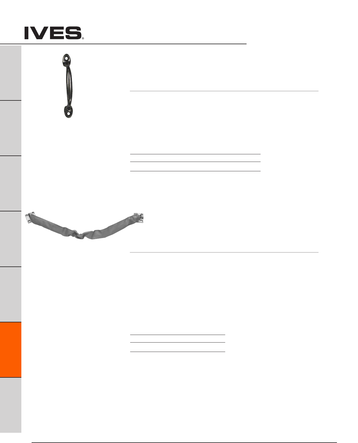
Ives Architectural hardware products
F10
Crash Stops
B
Pulls & Plates
A
Hinges & Pivots
C
Flush Bolts & Coordinators
D
Latches, Catches & Bolts
E
Stops
F10
Exterior Hardware
G
Miscellaneous Hardware
25 Screen Door Pull
• Castaluminumorepoxy-coatedaluminum
• Alsousedasawindowlift,drawerorutilitypull
Dimensions
Length 4-7/8"
Projection 1-5/32"
Mounting holes 4-1/8" center to center
Meets ANSI/BHMA A156.16, L12231,
Finishes
Ives Number A3 A92 A-W A-B
BHMA 666 673
CS115 Crash Stop
• Speciallydesignedforfull-sizeexteriordoors.
• Tearresistant,greyvinylcover.
• Heavydutycompressionspringassembledtobothendsofchain
and end brackets.
• Packedwithsheetmetalscrews.
• CastBrassbracketswithsolid,weldedsteelchain.
• OptionalsexboltmountingavailableinUS26D(626)only.
Dimensions
Bracket Size: 1-9/16" x 1-9/16"
Available Lengths:
20-1/2"—Recommendedfor30"DoorWidth(ProductNo.CS115-20)
25-1/2"—Recommendedfor36"DoorWidth(ProductNo.CS115-25)
30-1/2"—Recommendedfor42"DoorWidth(ProductNo.CS115-30)
Meets ANSI/BHMA A156.16, L12231,
Finishes
Ives Number US10B US26D
BHMA 613 626
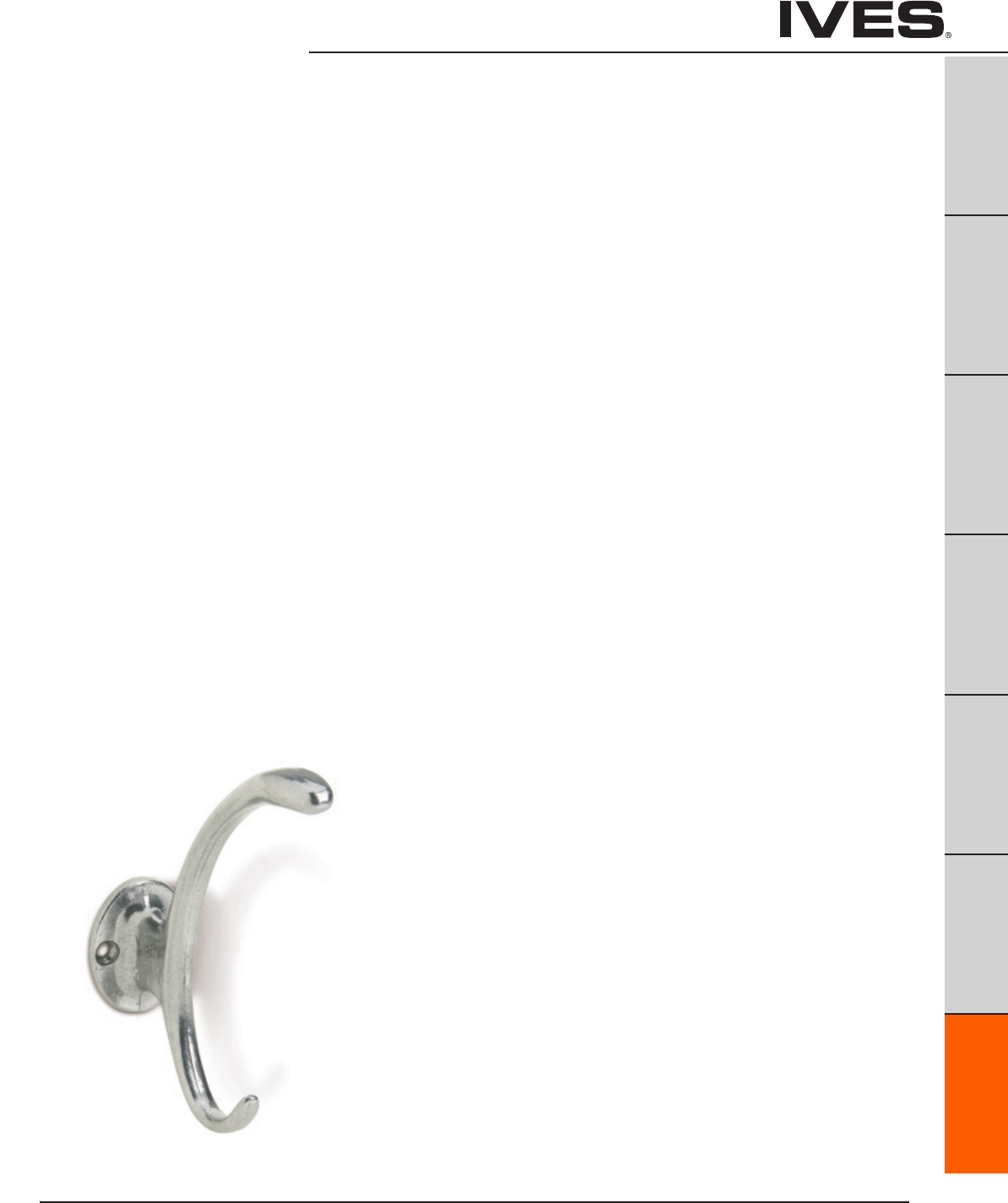
Ives Architectural hardware products G1
Miscellaneous Door Hardware
B
Pulls & Plates
A
Hinges & Pivots
C
Flush Bolts & Coordinators
D
Latches, Catches & Bolts
E
Stops
F
Exterior Hardware
G1
Miscellaneous Hardware
Table Of Contents
page
Hooks & Brackets
059 Handrail Bracket ................................................... G2
59 Handrail Bracket ....................................................G2
159 Handrail Bracket ...................................................G2
405 Coat & Hat Hook ................................................... G3
571 Coat & Hat Hook .................................................... G3
572 Coat & Hat Hook ...................................................G3
574 Coat & Hat Hook ...................................................G4
575 Coat & Hat Hook ...................................................G4
580 Ceiling Hook .......................................................G4
581 Wardrobe Hook. . . . . . . . . . . . . . . . . . . . . . . . . . . . . . . . . . . . . . . . . . . . . . . . . . . . . G5
582 Wardrobe Hook ....................................................G5
585 Closet Pole Socket .................................................G6
586 Closet Pole Socket .................................................G6
Window Hardware
07 Window Lock ........................................................G6
90 Side Window Lock .................................................. G7
026 Bar Window Lift ................................................... G7
066 Casement Fastener ................................................ G7
66 Casement Fastener .................................................G8
71 Casement Adjuster ...................................................G8
Hobby Hardware
78 Hook and Staple ....................................................G9
86 Hobbyist Barrel Bolt .................................................G9
9011, 9031 Middle Butt Hinge ...........................................G9
9041 Middle Butt Hinge .................................................G9
9042 Broad Butt Hinge .................................................G9
9070 Decorative Hinge ................................................G10
9071, 9072 Decorative Hinge ...........................................G10
9110 Decorative Hasp ..................................................G10
9120 Hasp .............................................................G10
9130 Hook with Hasp ...................................................G11
9210 Support Hinge ....................................................G11
9220 Friction Lid Support ...............................................G11
9311, 9212 Decorative Corner ............................................G11
9320 Bracket .......................................................... G12
9321 Bracket .......................................................... G12
9330 Draw Catch ...................................................... G12
9340 Chest Handle .................................................... G12
Cabinet/Closet Hardware
2 Elbow Catch ......................................................... G13
22 Flush Pull. . . . . . . . . . . . . . . . . . . . . . . . . . . . . . . . . . . . . . . . . . . . . . . . . . . . . . . . . . . G13
218 Finger Pull ......................................................... G13
221 Flush Pull ..........................................................G14
222 Flush Pull ......................................................... G14
223 Flush Pull ......................................................... G14
227 Flush Pull ......................................................... G15
230 Slide Door Edge Pull .............................................. G15
42 Pocket Sliding Door Bolt ............................................ G15
990 Sliding Door Pull ..................................................G16
991 Sliding Door Pull ...................................................G16
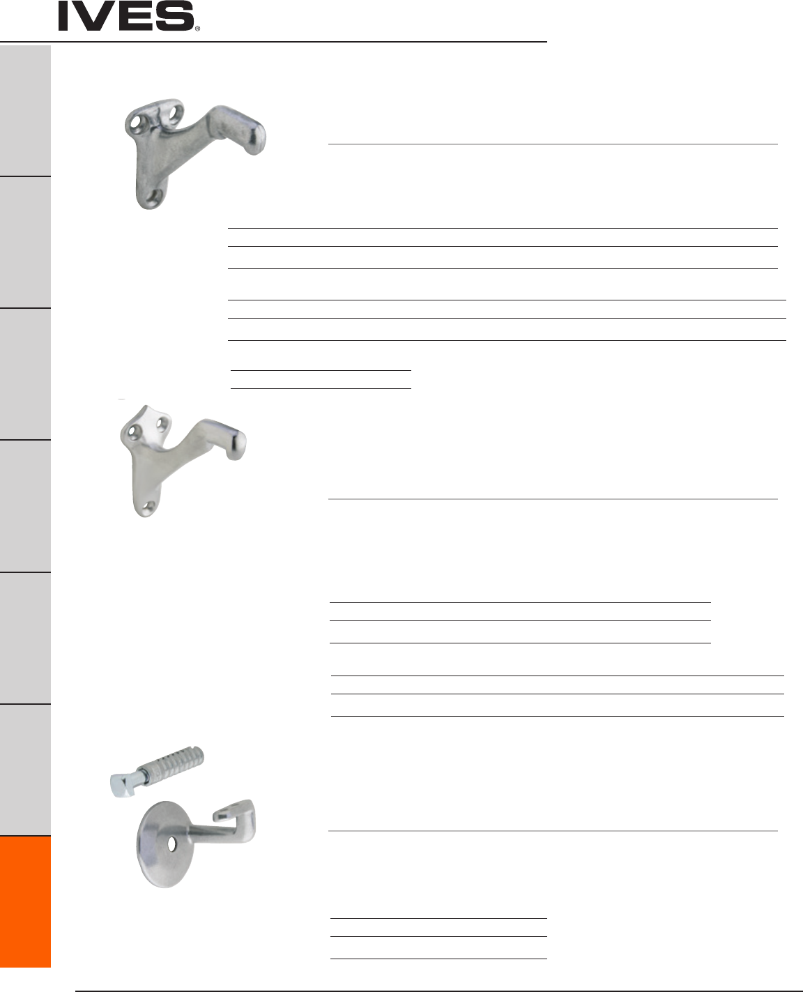
Ives Architectural hardware products
G2
Hand Rail Brackets and Hooks
B
Pulls & Plates
A
Hinges & Pivots
C
Flush Bolts & Coordinators
D
Latches, Catches & Bolts
E
Stops
F
Exterior Hardware
G2
Miscellaneous Hardware
59 Hand Rail Bracket
• Madefromcastbrassorcastaluminum.
• Largefaceplateforsecureattachmenttowall.
• Featuressolidconstructionforincreasedstrength.
Dimensions
Aluminum Base: 2-13/16" High x 1-1/2" Wide
Brass Base: 2-15/16" High x 1-1/2" Wide
Base to Center of Rail: 2-3/4"
159 Hand Rail Bracket
• Foruseoncommercialapplications.
• ExceedsOSHAandBHMAstrengthtestrequirements.
• Packedwithsquareheadironlagscrew,expansionshieldandscrews.
• CastAluminumconstruction.
Dimensions
Base Diameter: 3-1/8"
Base to Rail Center: 3-1/8"
Meets ANSI/BHMA A156.16 L13061
for brass and L33061 for aluminum
Meets ANSI/BHMA A156.16, L33081
Meets ANSI/BHMA A156.16 L13061
for brass and L33061 for aluminum
Finishes brass
Ives Number B3 B5 B15 B26 B26D B716
BHMA 605 609 619 625 626
Finishes aluminum
Ives Number A3 A5 A10B A14 A15 A92 A716
BHMA 666 703 669 670 673
Finishes aluminum
Ives Number A3 A92
BHMA 666 673
059 Hand Rail Bracket
• Madefromsolidbrass,castaluminumorepoxy-coatedaluminum.
• Largefaceplateforsecureattachmenttowall.
• Featuressolidconstructionforincreasedstrength.
Dimensions
Base: 2-1/4" High x 1-3/8" Wide
Base to Center of Rail: 2-7/16"
Finishes brass
Ives Number B3 B5 B10B B15 B15A B19 B26 B26D B716
BHMA 605 609 613 619 620 622 625 626
Finishes aluminum
Ives Number A3 A5 A10 A10B A14 A15 A92 A716 A-BLK A-W
BHMA 666 668 703 669 670 673
Finishes zinc
Ives Number Z619E
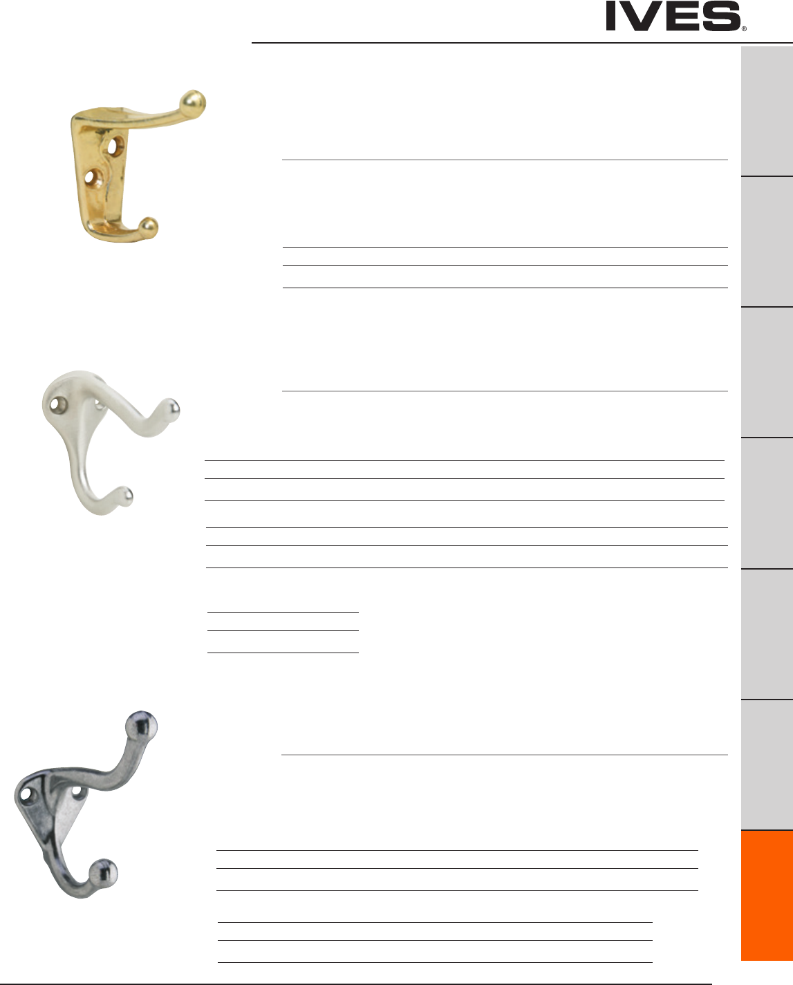
Ives Architectural hardware products G3
Hooks
B
Pulls & Plates
A
Hinges & Pivots
C
Flush Bolts & Coordinators
D
Latches, Catches & Bolts
E
Stops
F
Exterior Hardware
G3
Miscellaneous Hardware
572 Coat & Hat Hook
• Step-updecorativeversionofthetraditionalall-purposehook.
• Idealforlocationswhereadditionalstrengthisrequired.
• Madefromcastbrassorcastaluminum.
Dimensions
Brass Base: 1-1/2" High x 1-5/16" Wide
Aluminum Base: 1-5/8" High x 1-5/16" Wide
Projection: 3"
405 Coat & Hat Hook
• Widebodydesignisidealforpublicbuildings,schools,dormitories,
etc., where hook must withstand unusual stress and strain.
• Madefromcastaluminum.
Dimensions
Base: 1-1/2" High x 7/8" Wide
Projection: 2-1/2"
Meets ANSI/BHMA A156.16 L33113
Finishes brass
Ives Number B3 B4 B5 B10 B10B B15 B26 B26D
BHMA 605 606 609 612 613 619 625 626
Finishes aluminum
Ives Number A3 A5 A10 A10B A14 A15 A92
BHMA 666 668 703 669 670 673
Finishes aluminum
Ives Number A3 A4 A5 A10 A10B A14 A92
BHMA 666 667 668 703 669 673
571 Coat & Hat Hook
• All-purposehookintraditionaldesign.
• Madefromcastbrass,castaluminum,orepoxy-coatedaluminum.
Dimensions
Base: 1-3/4" High x 1-1/4" Wide
Projection: 3"
Meets ANSI/BHMA A156.16 L13113
for brass and L33113 for aluminum.
Finishes brass
Ives Number B3 B4 B5 B10B B15 B15A* B26 B26D B716
BHMA 605 606 609 613 619 620 625 626
Finishes aluminum
Ives Number A3 A5 A10 A14 A15 A92 A716 A-W A-BLK
BHMA 666 668 669 670 673
Finishes zinc
Ives Number Z619E
BHMA
* only available in Schlage Carded or Slim-Pak of 25
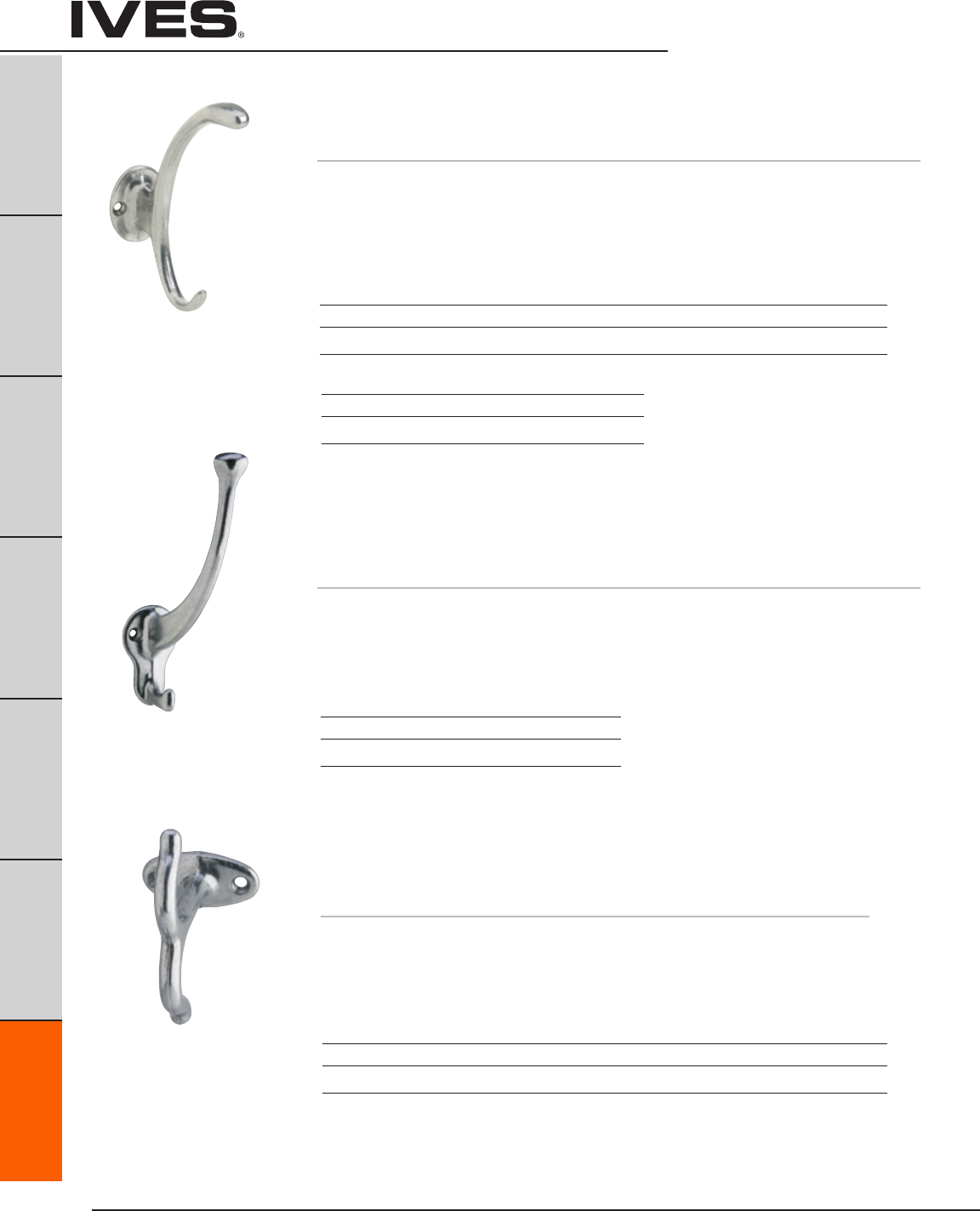
Ives Architectural hardware products
G4
Hooks
B
Pulls & Plates
A
Hinges & Pivots
C
Flush Bolts & Coordinators
D
Latches, Catches & Bolts
E
Stops
F
Exterior Hardware
G4
Miscellaneous Hardware
574 Coat & Hat Hook
• Decorativedesignisidealforcommercialandresidentialinstallations.
• Madefromcastbrass,castaluminumorepoxy-coatedaluminum.
Dimensions
Base: 1-5/8" High x 1-3/4" Wide
Projection: 3-3/4"
Overall Height, Brass: 4-3/4"
Overall Height, Aluminum: 5"
575 Coat & Hat Hook
• Especiallydesignedtoaccommodatelargehats.
• Madefromsolidbrassorcastaluminum.
Dimensions
Base: 2-1/4" High x 1-3/8" Wide
Projection: 3-5/8"
Overall Height: 5-3/4"
Meets ANSI/BHMA A156.16 L13113 for
brass and L33113 for aluminum
Meets ANSI/BHMA A156.16 L33121
Finishes brass
Ives Number B3 B4 B10 B10B B15 B26 B26D
BHMA 605 606 612 613 619 625 626
Finishes aluminum
Ives Number A3 A26 A92
BHMA 666 672 673
Finishes aluminum
Ives Number A3 A10B A92
BHMA 666 703 673
580 Ceiling Hook
• Idealforuseinclosets,attachedtoundersideofshelves,
or in storage lockers.
• Madefromcastbrassorcastaluminum.
Dimensions
Base: 1" High x 1-7/8" Wide
Projection: 2-1/4"
Finishes
Ives Number A3 A5 A10 A14 A15 A92 A716
BHMA 666 668 669 670 673
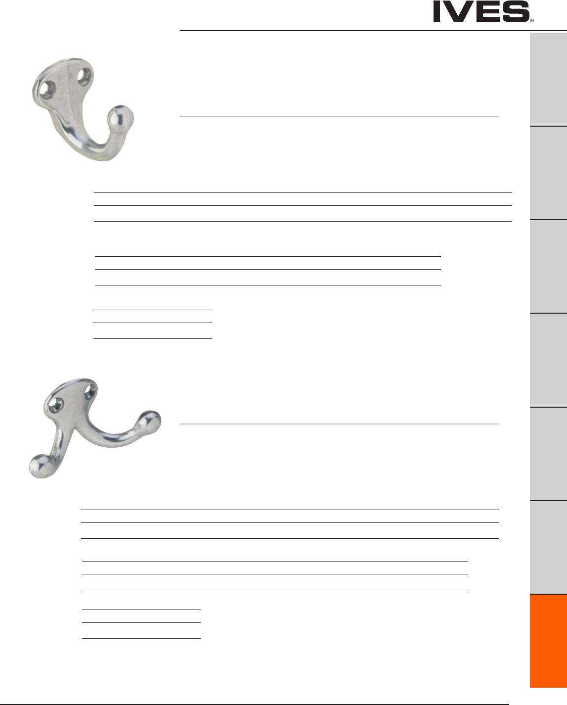
Ives Architectural hardware products G5
Hooks
B
Pulls & Plates
A
Hinges & Pivots
C
Flush Bolts & Coordinators
D
Latches, Catches & Bolts
E
Stops
F
Exterior Hardware
G5
Miscellaneous Hardware
581 Wardrobe Hook
• Compacthookisperfectwherespaceislimited,
such as behind doors where low profile is needed.
• Madefromcastbrass,castaluminumorepoxy-coatedaluminum.
Dimensions
Base, Brass/Aluminum: 1-1/4" High x 1-1/4" Wide
Base, Zinc: 1-1/2" High x 3/4" Wide
Projection, Brass: 1-11/16"
Projection, Aluminum, Zinc: 1-5/8"
582 Double Wardrobe Hook
• Compactdoublehookisperfectwherespaceislimited,
such as behind doors where low profile is needed.
• Madefromcastbrass,castaluminumorepoxy-coatedaluminum.
Dimensions
Base, Brass: 1-1/8" High x 1-1/4" Wide
Base, Aluminum: 1-1/16" High x 1-3/16 Wide
Base, Zinc: 1-5/8" High x 7/8" Wide
Projection, Brass: 1"
Projection, Aluminum, Zinc: 1-3/32"
Finishes brass
Ives Number B3 B4 B5 B10 B10B B15 B15A* B26 B26D B716
BHMA 605 606 609 612 613 619 620 625 626
* only available in Schlage Carded
Finishes aluminum
Ives Number A3 A5 A14 A15 A92 A716 A-BLK A-W
BHMA 666 669 670 673
Finishes zinc (narrow base)
Ives Number Z619E
BHMA
Finishes zinc (narrow base)
Ives Number Z619E
BHMA
Finishes brass
Ives Number B3 B4 B5 B10 B10B B15 B15A* B26 B26D B716
BHMA 605 606 609 612 613 619 620 625 626
Finishes aluminum
Ives Number A3 A5 A10 A14 A15 A92 A716 A-W A-BLK
BHMA 666 668 669 670 673
* only available in Schlage Carded or Slim-Pak of 25

Ives Architectural hardware products
G6
Window Hardware
B
Pulls & Plates
A
Hinges & Pivots
C
Flush Bolts & Coordinators
D
Latches, Catches & Bolts
E
Stops
F
Exterior Hardware
G6
Miscellaneous Hardware
SP585 Closet Pole Sockets
• Flangedesignpreventsaccidentalknockoutofpole.
• Madefromwroughtsteel.
• Accommodatespoleorpipewithoutsidediameterof1-3/8".
• Packedinpairs.
Finishes
Ives Number F3
BHMA 632
07 Window Lock
• Designedlowtothesashforsuperiorstrengthandgreater
resistance to breakage.
• Verticalandhorizontalcammingactionforsnug,non-rattlingfit.
• Heavygaugespringsprovidelong-wearingaction.
• Madefromsolidbrass,aluminum,orepoxycoatedaluminum.
Dimensions
Base: 15/16" x 2-9/16"
Strike: 5/8" x 2-9/16"
Finishes brass
Ives Number B3 B15 B15A* B26 B26D B716
BHMA 605 619 620 625 626
Meets ANSI/BHMA A156.16
Finishes aluminum
Ives Number A3 A5* A10B A14 A15 A92 A-716 A-W A-BLK
BHMA 666 703 669 670 673
SP586 Closet Pole Sockets
• Madefromaheavydutyplasticforlonglifeandextrastrength.
• Singlescrewmounting.
• Accommodatespoleorpipewithoutsidediameterof1-3/8".
• Packedinpairs.
Finish
White Plastic
* only available in Schlage Carded or Slim-Pak of 25
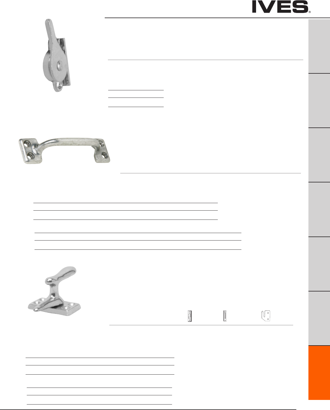
Ives Architectural hardware products G7
Window Hardare
B
Pulls & Plates
A
Hinges & Pivots
C
Flush Bolts & Coordinators
D
Latches, Catches & Bolts
E
Stops
F
Exterior Hardware
G7
Miscellaneous Hardware
90 Side Window Lock
• Maybeusedsingularlyforsmallwindowsorinpairsforlargewindows.
• Camactioneliminatesrattlesandholdswindowfirmlyindesiredposition.
• Madefromaluminum.
Dimensions
1-3/4" High x 1-1/8" Wide
Finishes
Ives Number A3
BHMA 666
Meets ANSI/BHMA A156.16
026 Bar Window Lift
• Facilitatesopeningofwindowinasafemanner.
• Canalsobeusedasadrawerorutilitypull.
• Madefromsolidbrass,aluminum,orepoxycoatedaluminum.
Dimensions
Base: 1-1/8" High x 4" Wide
Projection: 1-1/16"
Meets ANSI/BHMA A156.16
Finishes brass
Ives Number B3 B5 B15 B15A* B26 B26D B716
BHMA 605 609 619 620 625 626
Finishes aluminum
Ives Number A3 A5 A14 A15 A92 A716 A-W A-BLK
BHMA 666 669 670 673
066 Casement Fastener
• Foruseonwindowstoprovideweather-tightfasteningandsecurity.
• Alsoidealforsecuringlouvereddoorsandsmalldoors.
• Madefromsolidbrassoraluminum.
• Specify:Surface, Rim,or Mortise
Strike (SS) Strike (RS) Strike (MS)
Dimensions
Base: 1-5/8" x 7/8"
Projection: 1-3/8"
Meets ANSI/BHMA A156.16
Finishes brass
Ives Number B3 B5 B15 B26 B26D
BHMA 605 609 619 625 626
Finishes aluminum
Ives Number A3 A5 A10B A14 A92
BHMA 666 668 703 673
* only available in Schlage Carded or Slim-Pak of 25
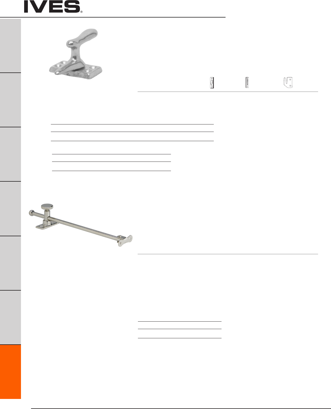
Ives Architectural hardware products
G8
Window Hardware
B
Pulls & Plates
A
Hinges & Pivots
C
Flush Bolts & Coordinators
D
Latches, Catches & Bolts
E
Stops
F
Exterior Hardware
G8
Miscellaneous Hardware
66 Casement Fastener
• Foruseonwindowstoprovideweather-tightfasteningandsecurity.
• Alsoidealforsecuringlouvereddoorsandsmalldoors.
• Madefromsolidbrassoraluminum.
• Specify:Surface,Rim Mortise
Strike (SS) Strike (RS) Strike (MS)
Dimensions
Base: 2-1/16" High x 1-1/16" Wide
Projection: 1-7/8"
Meets ANSI/BHMA A156.16
Finishes brass
Ives Number B3 B5 B15 B26 B26D B716
BHMA 605 609 619 625 626
Finishes aluminum
Ives Number A3 A5 A14 A92
BHMA 666 669 673
71 Casement Adjuster
• Securelyholdscasementwindowinanyposition.
• Canalsobeusedtoholdcabinetlidsanddraftingtabletopsin
various positions.
• Madefromburnishedsteelorsolidbrass.
• Availablein10"and12"lengths.
Dimensions
Tube: 3/8" x 5/8"
Projection: 1"
Sash Plate:
Brass: 1-5/8" High x 5/8" Wide
Steel: 2 x 5/8" Wide
Sill Plate:
2-1/4" x 15/16" Wide
Meets ANSI/BHMA A156.16
Finishes brass
Ives Number B3 B26
BHMA 605 625
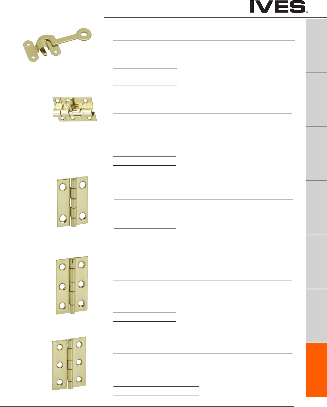
Ives Architectural hardware products G9
Hobby Hardware
B
Pulls & Plates
A
Hinges & Pivots
C
Flush Bolts & Coordinators
D
Latches, Catches & Bolts
E
Stops
F
Exterior Hardware
G9
Miscellaneous Hardware
78 Hook and Staple
• Madefromsolidbrass.
Dimensions
Hook: 1-1/2” Long
Staple: 3/4” high x 15/16” wide
Finishes
Ives Number B3
BHMA 605
86 Hobbyist Barrel Bolt
• Madefromsolidbrass.
Dimensions
Bolt plate: 1-9/16” high x 1-11/16” wide
Bolt guide: 1-9/16” high x 7/16” wide
Strike plate: 1-9/16” high x 5/8” wide
Finishes
Ives Number B3
BHMA 603
9011 Middle Butt Hinge
9031 Middle Butt Hinge
• Madefromsolidbrass.
Dimensions
9011 Overall height x overall width: 3/4” x 11/16”
9031 Overall height x overall width: 1-1/2” x 1”
Finishes
Ives Number B3
BHMA 605
9042 Broad Butt Hinge
• Madefromsolidbrass.
Dimensions
Overall height x overall width: 2” x 1-3/8”
Finishes
Ives Number B3 B5
BHMA 605 609
9041 Middle Butt Hinge
• Madefromsolidbrass.
Dimensions
Overall height x overall width: 2” x 1-1/4”
Finishes
Ives Number B3
BHMA 605
Schlage Carded - 9011 4 per, 5 cards per box. 9031 2 per, 5 cards per box.
Schlage Carded - 2 per, 5 cards per box.
Schlage Carded - 2 per, 5 cards per box.
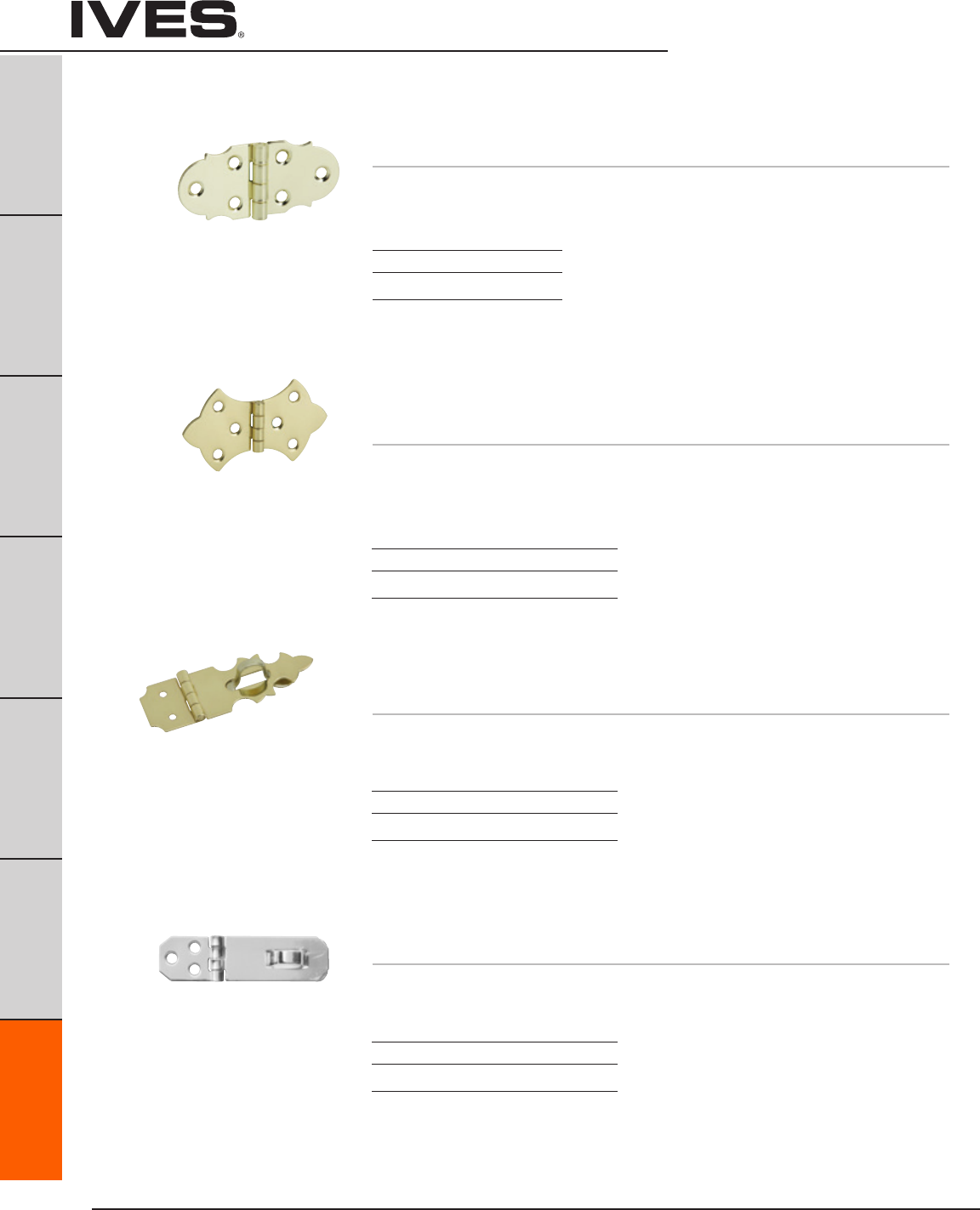
Ives Architectural hardware products
G10
Hobby Hardware
B
Pulls & Plates
A
Hinges & Pivots
C
Flush Bolts & Coordinators
D
Latches, Catches & Bolts
E
Stops
F
Exterior Hardware
G10
Miscellaneous Hardware
9070 Decorative Hinge
• Madefromsteel.
Dimensions
Overall height x overall width: 1-5/16” x 2-7/8”
Finishes
Ives Number F3
BHMA 632
9071 Decorative Hinge
9072 Decorative Hinge
• Madefromsolidbrass.
Dimensions
9071 Overall height x overall width: 1-3/4” x 3”
9072 Overall height x overall width: 1-5/16” x 2-1/4”
Finishes
Ives Number B3 B5
BHMA 605 609
9110 Decorative Hasp
• Madefromsolidbrass.
Dimensions
Overall height x overall width: 5/8” x 1-7/8”
Finishes
Ives Number B3 B5
BHMA 605 609
9120 Hasp
• Madefromsolidbrass.
Dimensions
Overall height x overall width: 3/4” x 2-3/4”
Finishes
Ives Number B3 B5
BHMA 605 609
Schlage Carded - 2 per, 5 cards per box.
Schlage Carded - 2 per, 5 cards per box.
Schlage Carded - 1 per card, 5 cards per box.
Schlage Carded - 1 per card, 5 cards per box.
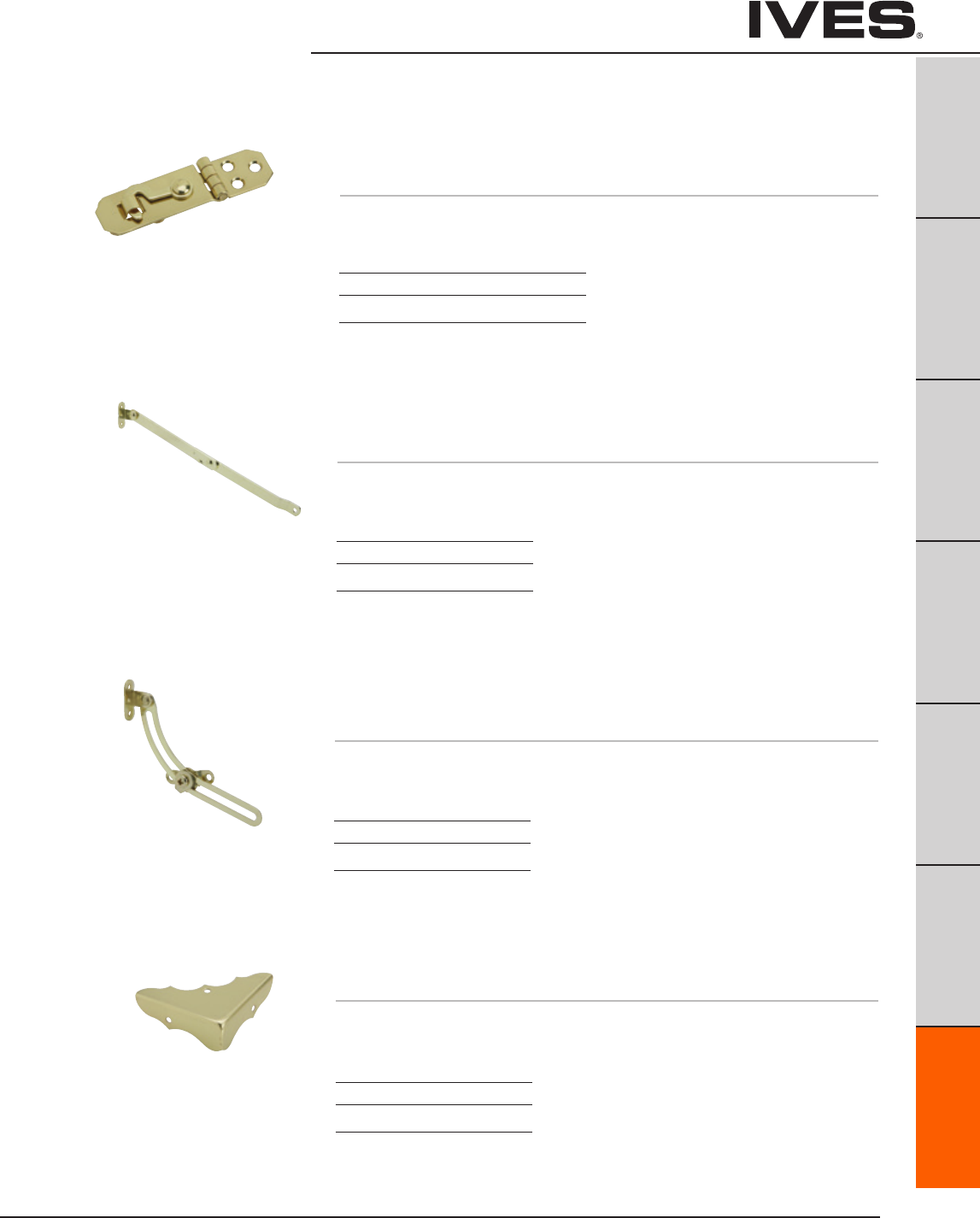
Ives Architectural hardware products G11
Hobby Hardware
B
Pulls & Plates
A
Hinges & Pivots
C
Flush Bolts & Coordinators
D
Latches, Catches & Bolts
E
Stops
F
Exterior Hardware
G11
Miscellaneous Hardware
9130 Hook with Hasp
• Madefromsolidbrass.
Dimensions
Overall height x overall width: 3/4” x 2-3/4”
Finishes
Ives Number B3
BHMA 605
9210 Support Hinge
• Madefromsteel.
• Handed.SpecifyLeftHand(LH)orRightHand(RH)
Dimensions
Extension: approx. 10-3/8”
Finishes
Ives Number F3
BHMA 632
9220 Friction Lid Support
• Madefromsteel.
• Handed.SpecifyLeftHand(LH)orRightHand(RH)
Dimensions
Extension: approx. 5”
Finishes
Ives Number F3
BHMA 632
9311 Decorative Corner
• Madefromsolidbrass.
Dimensions
9311 Side to corner: 1-3/4”
Finishes
Ives Number B3
BHMA 605
Schlage Carded - 1 per, 5 cards per box.
Schlage Carded - 1 per, 5 cards per box.
Schlage Carded - 1 per, 5 cards per box.
Schlage Carded - 4 per card, 5 cards per box.
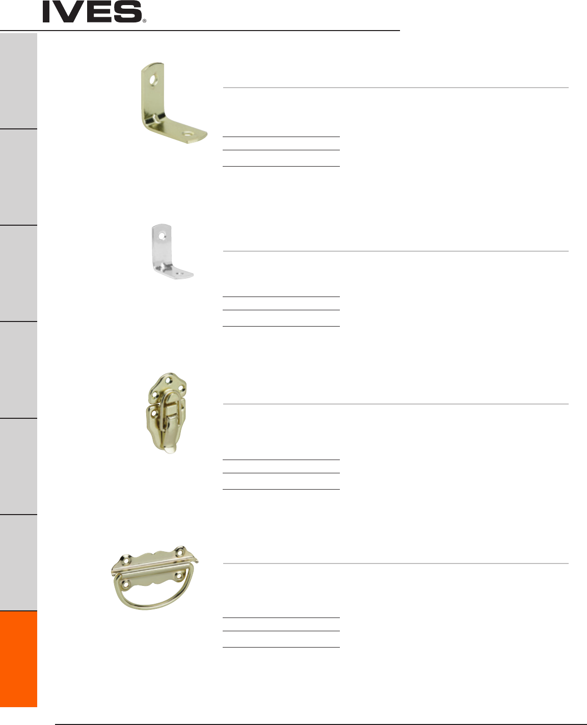
Ives Architectural hardware products
G12
Hobby Hardware
B
Pulls & Plates
A
Hinges & Pivots
C
Flush Bolts & Coordinators
D
Latches, Catches & Bolts
E
Stops
F
Exterior Hardware
G12
Miscellaneous Hardware
9320 Bracket
• Madefromsolidbrass.
Dimensions
Each leaf 1/2” x 1-1/8”
Finishes
Ives Number B3
BHMA 605
9321 Bracket
• Madefromsolidbrass.
Dimensions
Each leaf 1/2” x 1-9/16”
Finishes
Ives Number B3
BHMA 605
9330 Draw Catch
• Madefromsteel.
Dimensions
Overall height: 1-1/2”
Overall width: 2-3/4”
Finishes
Ives Number F3
BHMA 632
9340 Chest Handle
• Madefromsteel.
Dimensions
Overall height: 1-1/2”
Overall width: 3-1/2”
Finishes
Ives Number F3
BHMA 632
Schlage Carded - 4 per, 5 cards per box.
Schlage Carded - 4 per, 5 cards per box.
Schlage Carded - 2 per, 5 cards per box.
Schlage Carded - 2 per, 5 cards per box.
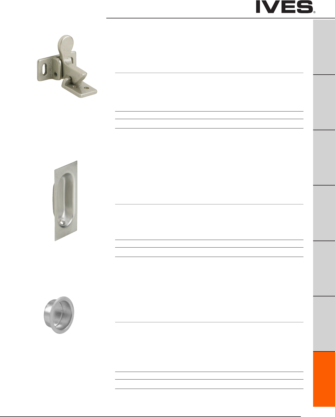
Ives Architectural hardware products G13
Cabinet/Closet Knobs and Pulls
B
Pulls & Plates
A
Hinges & Pivots
C
Flush Bolts & Coordinators
D
Latches, Catches & Bolts
E
Stops
F
Exterior Hardware
G13
Miscellaneous Hardware
2 Elbow Catch
• Idealforuseontheinactiveleafofapairofcabinetdoors.
• Surfaceapplied,makinginstallationsimple.
• Madefromcastaluminum.
Dimensions
Plate: 1-3/8" High x 5/8" Wide
Strike: 13/16" High x 5/8" Wide
22 Flush Pull
• Lowprofilemakesthispullidealforlouvered,bi-foldingor
wardrobe doors.
• Extradeeprecessandreversetaperedgripprovideforeaseofpulling
and gripping.
• Madefromwroughtbrass.
Dimensions
1-5/16" High x 3-1/8" Wide x 7/16" Deep
Finishes aluminum
Ives Number A3 A5 A14 A15 A92 A716
BHMA 666 669 670 673
Finishes brass
Ives Number B3 B5 B10B B15 B26 B26D
BHMA 605 609 613 619 625 626
Meets ANSI/BHMA A156.9 B33023
Meets ANSI/BHMA A156.9 B22201
and A156.14 D2781.
218 Finger Pull
• Idealforuseonslidingdoors.
• Easyinstallation.
• Madefromwroughtbrass.
Dimensions
Inside Cup Diameter: 3/4"
Overall Diameter: 1"
Depth: 5/16"
Finishes brass
Ives Number B3 B5 B10 B10B B15 B26 B26D
BHMA 605 609 612 613 619 625 626
Meets ANSI/BHMA A156.9 B22201
and A156.14 D2781.
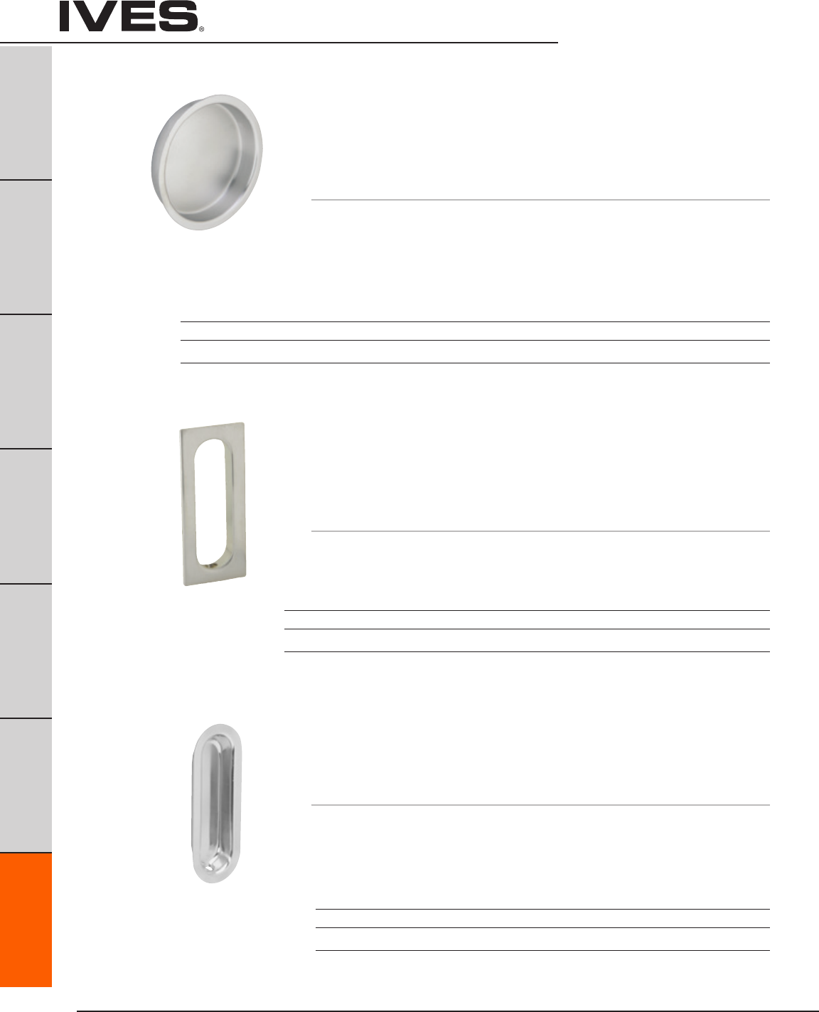
Ives Architectural hardware products
G14
Cabinet/Closet Knobs and Pulls
B
Pulls & Plates
A
Hinges & Pivots
C
Flush Bolts & Coordinators
D
Latches, Catches & Bolts
E
Stops
F
Exterior Hardware
G14
Miscellaneous Hardware
222 Flush Pull
• Lowprofilemakesthispullidealforlouvered,bi-foldingor
wardrobe doors.
• Reversetaperedgripprovideforeaseofpulling.
• Madefromcastbrass.
Dimensions
3-1/8" High x 1-5/8" Wide x 7/16" Deep
Meets ANSI/BHMA A156.9 B22201
and A156.14 D2781
Meets ANSI/BHMA A156.9 B12201
and A156.14 D1781.
221 Flush Pull
• Idealforuseonslidingdoors.
• Built-inprongdesigneliminatestheneedforscrewsorbradsand
facilitates installation.
• Packedwithtwoescutcheonpinsforaddedholdingpower.
• Madefromwroughtbrass.
Dimensions
Inside Cup Diameter: 2-1/8"
Overall Diameter: 2-7/16"
Depth: 7/16"
Finishes brass
Ives Number B3 B4 B5 B10 B10B B15 B15A* B26 B26D B716
BHMA 605 606 609 612 613 619 620 625 626
* only available in Slim-Pak of 25
Finishes brass
Ives Number B3 B4 B5 B10 B10B B15 B26 B26D
BHMA 605 606 609 612 613 619 625 626
223 Flush Pull
• Lowprofilemakesthispullidealforlouvered,bi-folding
or wardrobe doors.
• Madefromwroughtbrass
Dimensions
3-9/16" High x 1-5/16" Wide x 1/2" Deep
Meets ANSI/BHMA A156.9 B22201
and A156.14 D2781.
Finishes brass
Ives Number B3 B4 B10 B10B B15 B26 B26D
BHMA 605 606 612 613 619 625 626
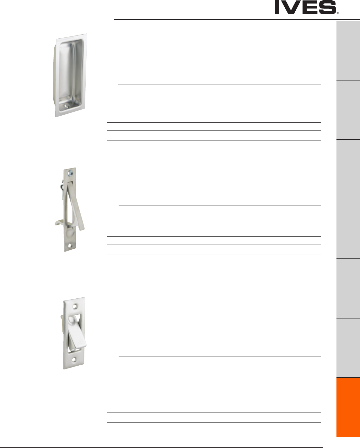
Ives Architectural hardware products G15
Cabinet/Closet Knobs and Pulls
B
Pulls & Plates
A
Hinges & Pivots
C
Flush Bolts & Coordinators
D
Latches, Catches & Bolts
E
Stops
F
Exterior Hardware
G15
Miscellaneous Hardware
230 Sliding Door Edge Pull
• 3/4"widthallowsinstallationonnarrowaswellasstandarddoors.
• Springautomaticallyreturnsleverflushwithplate.
• Madefromsolidbrass.
Dimensions
3-7/8" High x 3/4" Wide
227 Flush Pull
• Contouredforeaseofpulling.
• Extradeepwell.
• Deluxequality.
• Madefromwroughtbrass.
Dimensions
3-5/8" High x 1-3/4" Wide x 9/16" Deep
Meets ANSI/BHMA A156.9 B22201
and A156.14 D2781.
Meets ANSI/BHMA A156.14 D2801.
Finishes
Ives Number B3 B4 B5 B10 B10B B15 B26 B26D
BHMA 605 606 609 612 613 619 625 626
Finishes
Ives Number B3 B4 B5 B10 B10B B15 B26 B26D
BHMA 605 606 609 612 613 619 625 626
Finishes
Ives Number B3 B4 B5 B10 B10B B15 B26 B26D
BHMA 605 606 609 612 613 619 625 626
42 Pocket Sliding Door Bolt
• Exclusive Ives design permits emergency release of bolt from
outside the door.
• Springactivateddesignallowsfeather-touchaction.
• Brassgrommetsuppliedtocapreleasehole,protectingthe
door’s finish.
• Madefromwroughtbrass.
Dimensions
Overall Size Plate: 3-1/16" High x 1-5/32" Wide
Strike: 1" High x 3/4" Wide
Depth of Mortise: 5/8"
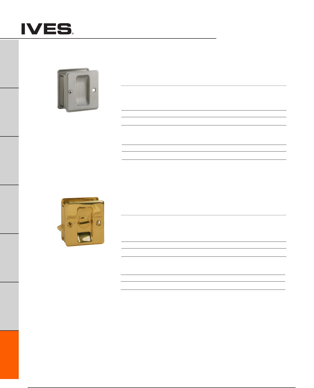
Ives Architectural hardware products
G16
Cabinet/Closet Knobs and Pulls
B
Pulls & Plates
A
Hinges & Pivots
C
Flush Bolts & Coordinators
D
Latches, Catches & Bolts
E
Stops
F
Exterior Hardware
G16
Miscellaneous Hardware
991 Sliding Door Pull
• Fitsdoors1-3/8"to1-1/2".
• Decorativecoinededges.
• Pre-assembledfordoorsopeninglefttoright.Platesarereversible.
• Body,turnknobandstrikemadefromsolidbrass.
Dimensions
1-3/4" D x 2-1/4" H
990 Sliding Door Pull
• Fitsdoors1-3/8"to1-1/2".
• Decorativecoinededges.
• Pre-assembledfordoorsopeninglefttoright.Platesarereversible.
• Bodyandstrikemadefromsolidbrass.
Dimensions
1-3/4" D x 2-1/4" H
Finishes brass
Ives Number B3 B5* B10B B15 B15A* B26 B716
BHMA 605 609 613 619 620 625
* only available in Schlage Carded
Finishes aluminum
Ives Number A3 A5 A14 A15 A26D A716
BHMA 666 669 670 702
Finishes brass
Ives Number B3 B5* B10B B15 B15* B26 B716
BHMA 605 609 613 619 620 625
* only available in Schlage Carded
Finishes aluminum
Ives Number A3 A5 A14 A15 A26D A716
BHMA 666 669 670 702

Ives Architectural hardware products G17
B
Pulls & Plates
A
Hinges & Pivots
C
Flush Bolts & Coordinators
D
Latches, Catches & Bolts
E
Stops
F
Exterior Hardware
G17
Miscellaneous Hardware

Allegion (NYSE: ALLE) creates peace of mind by pioneering safety and security.
As a $2 billion provider of security solutions for homes and businesses, Allegion
employs more than 7,800 people and sells products in more than 120 countries
across the world. Allegion comprises 23 global brands, including strategic
brands CISA®
, Interex®
, LCN®
, Schlage® and Von Duprin®
.
For more, visit www.allegion.com
About Allegion
© 2014 Allegion
005313, Rev. 02/14
www.allegion.com/us
