Ixia EE11ABG3 802.11 a/b/g Emulation Engine User Manual EmulationEngine 11a b g User s Guide
Ixia 802.11 a/b/g Emulation Engine EmulationEngine 11a b g User s Guide
Ixia >
Contents
- 1. User Manual part 1
- 2. User Manual part 2
- 3. User Manual part 3
User Manual part 1


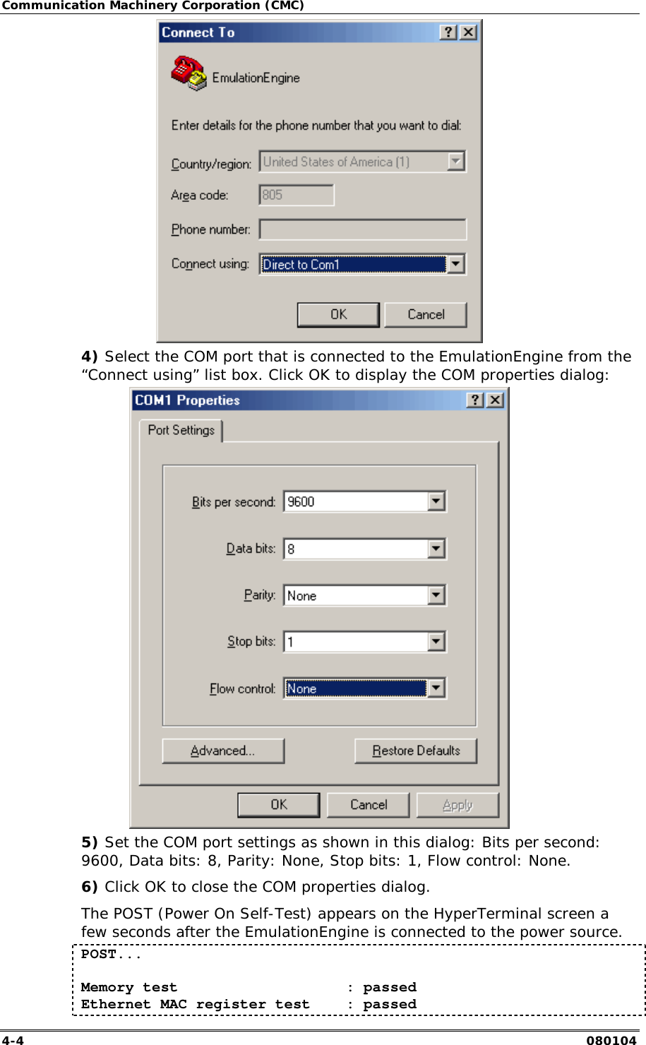
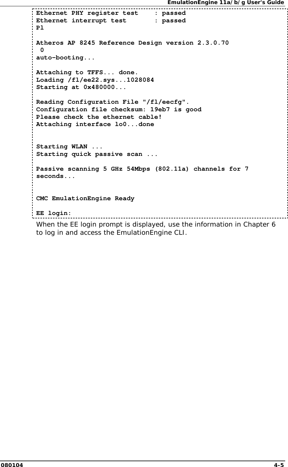

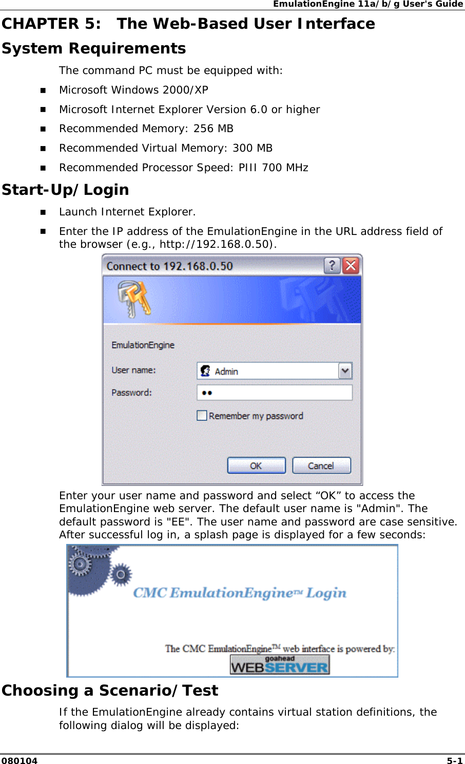
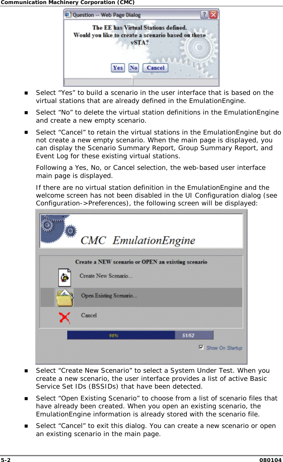
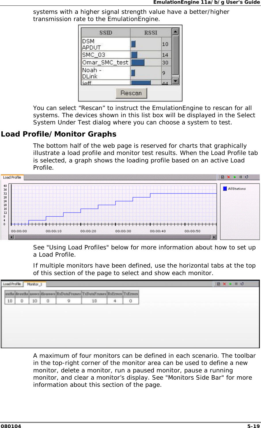
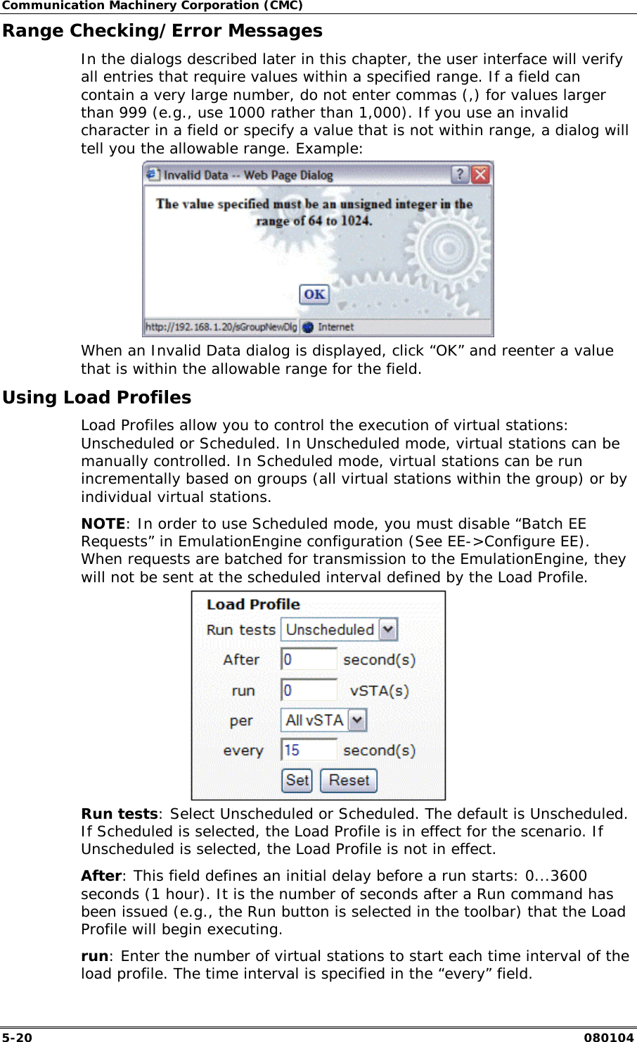
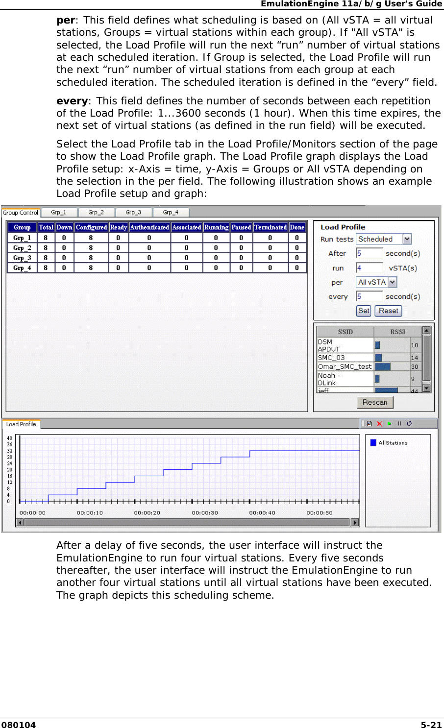
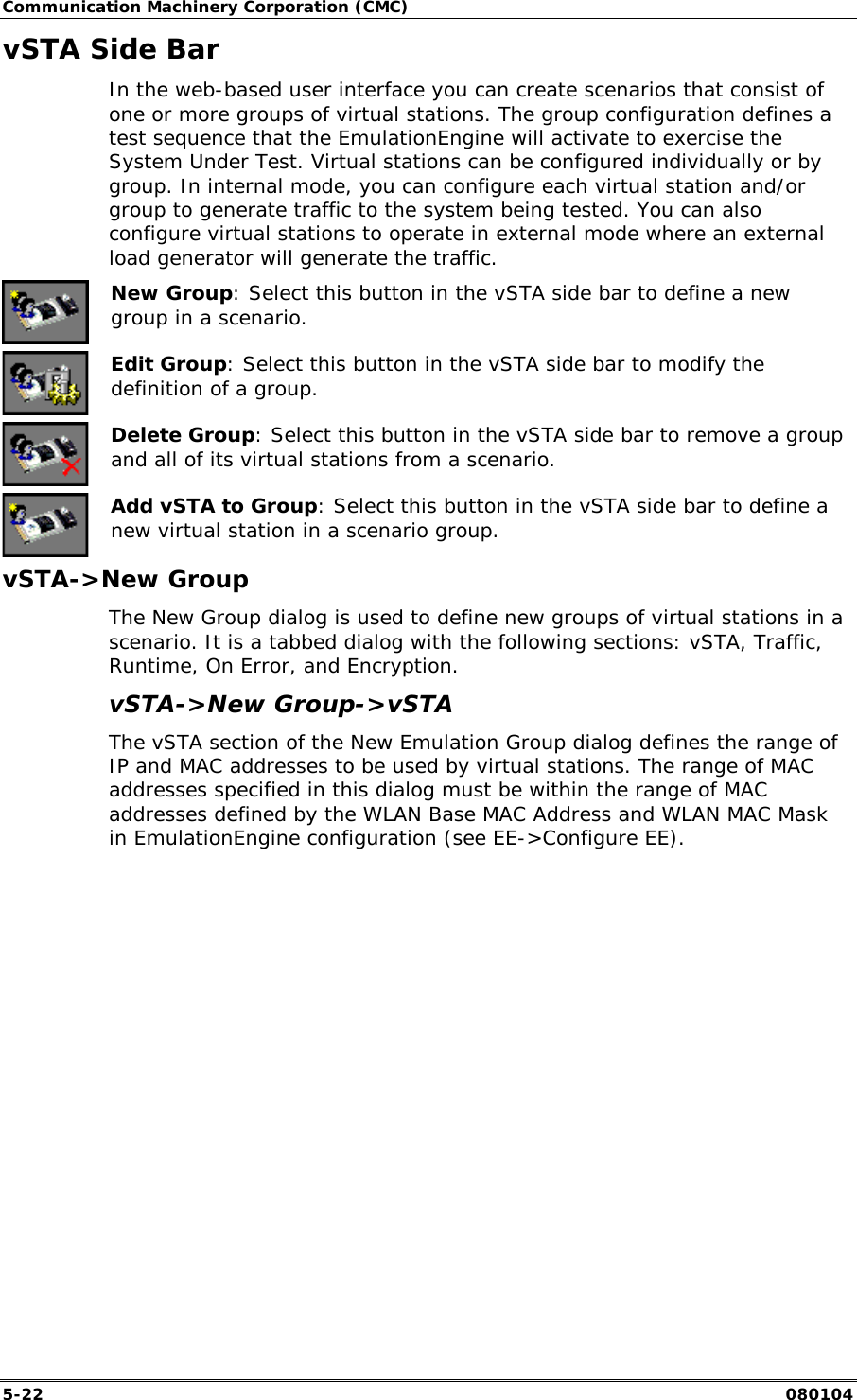
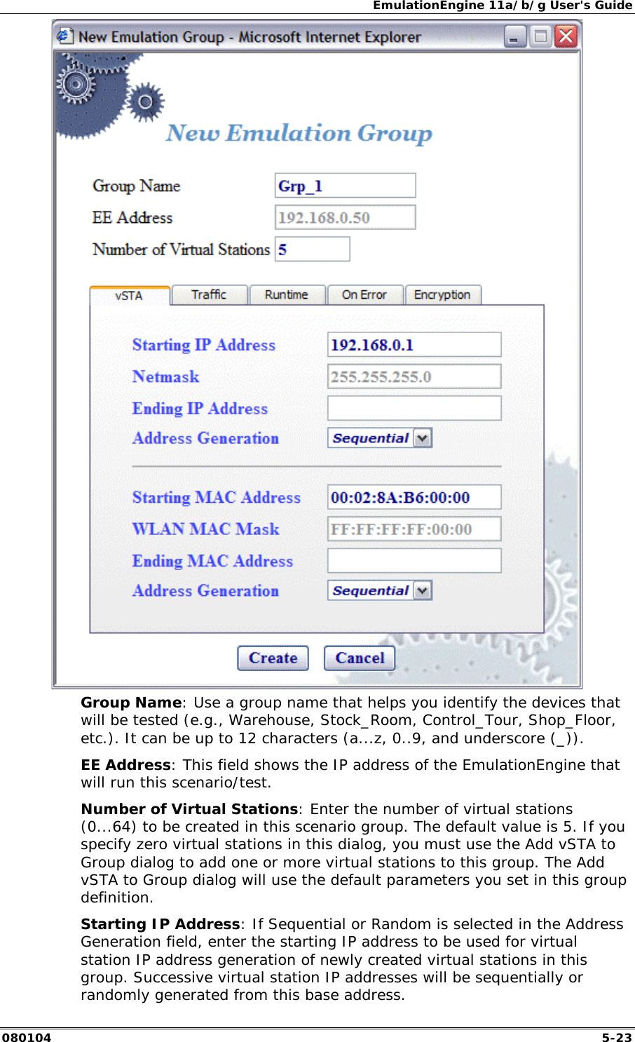
![Communication Machinery Corporation (CMC) 5-18 080104 Group Tab Columns: Within a group, you can double click on the table heading to configure the columns that are displayed. Select one or more items in the All Columns list box and click the [>>] button to move them to the Selected Columns list box. Click “Modify” to add the columns to the group table. Select “Reset” to return the columns to their default setting. Load Profile The Load Profile section of the page can be used to automatically execute scenarios at scheduled intervals. When automatic scheduling is defined, the grid below the Scheduling/Group table will chart the status of each virtual station over the period of the test. See "Using Load Profiles" below for more information about using this feature. Target Systems Below Load Profile, the main page displays a list of target systems and their signal strength in relationship to the EmulationEngine. Target](https://usermanual.wiki/Ixia/EE11ABG3.User-Manual-part-1/User-Guide-421986-Page-42.png)