Ixia GC617644 802.11a/b/g Multi AP Emulator (Client Device) User Manual IxWLANUserGuide
Ixia 802.11a/b/g Multi AP Emulator (Client Device) IxWLANUserGuide
UserManual.wiki
>
Ixia
>
GC617644 User Manual
>
User Manual 1
Contents
1.
User Manual 1
2.
User Manual 2
3.
Users Manual rev 1 part 1 of 2
4.
Users Manual rev 1 part 2 of 2
User Manual 1
Navigation menu
Upload a User Manual
Namespaces
Wiki Guide
HTML
PDF
Info
Views
User Manual
Discussion / Help
Navigation

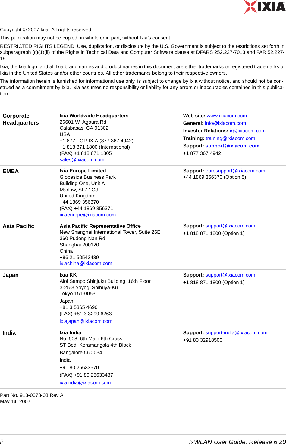
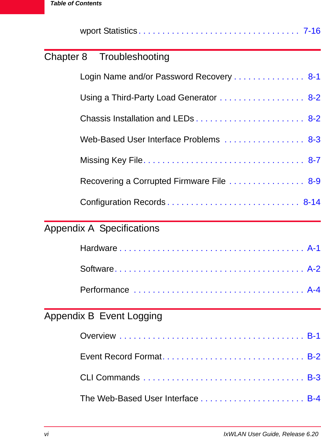

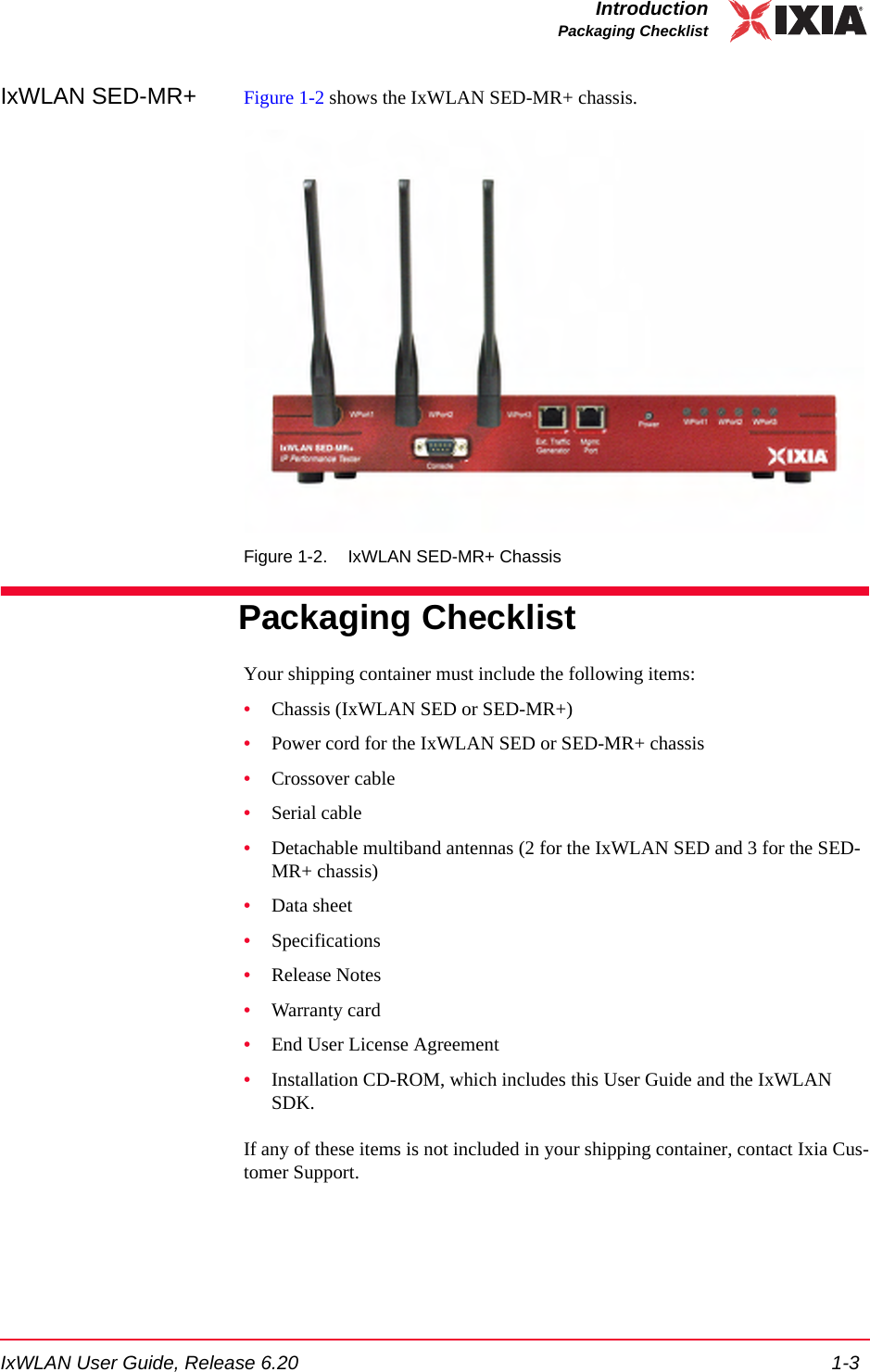

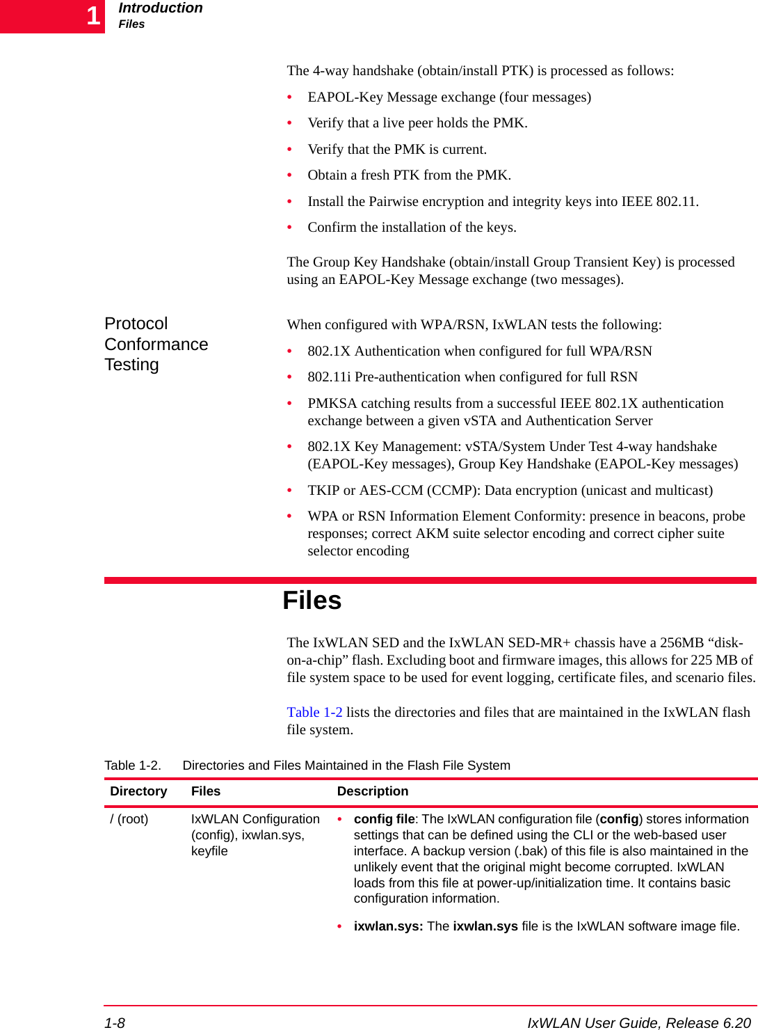

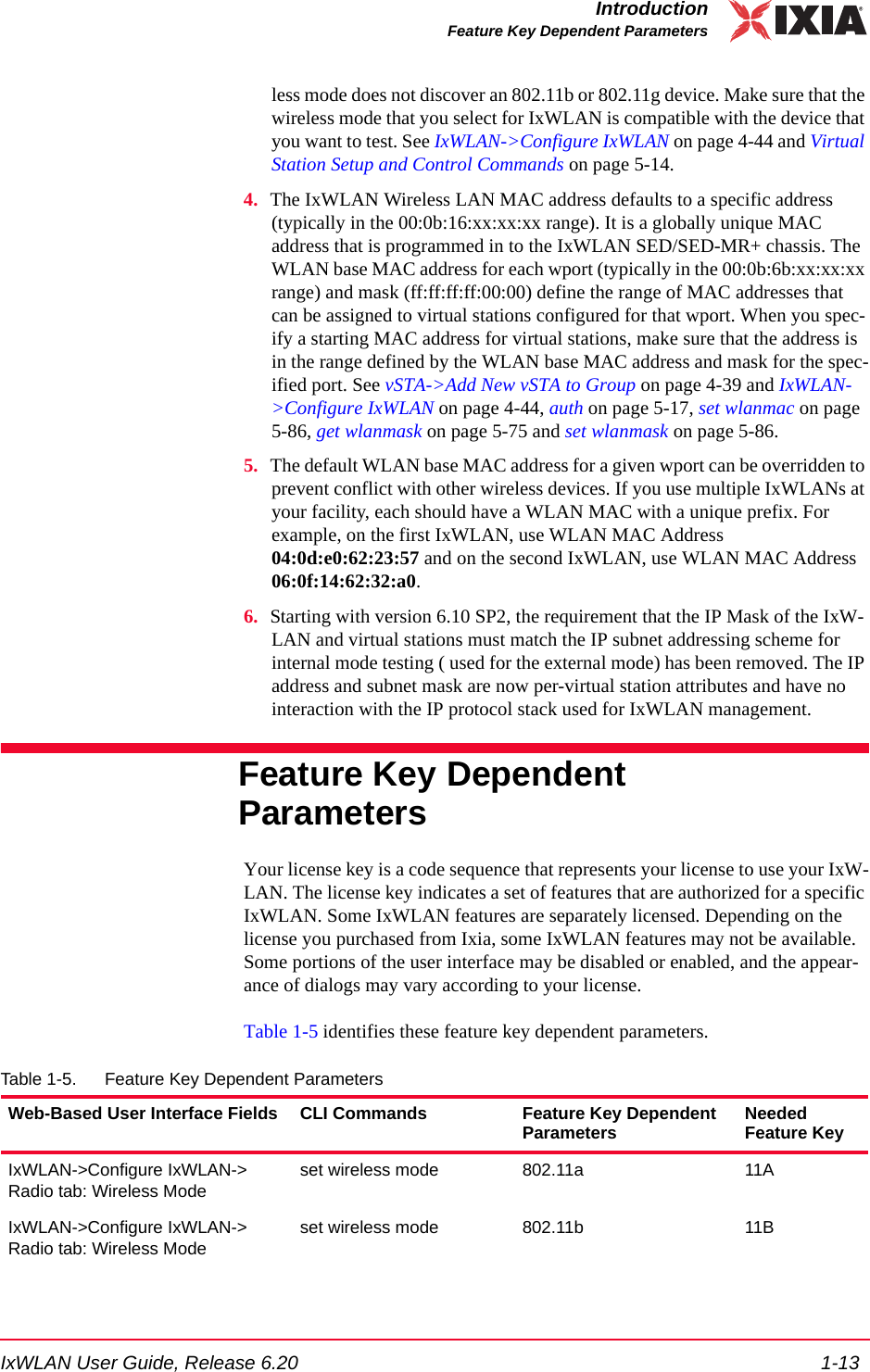
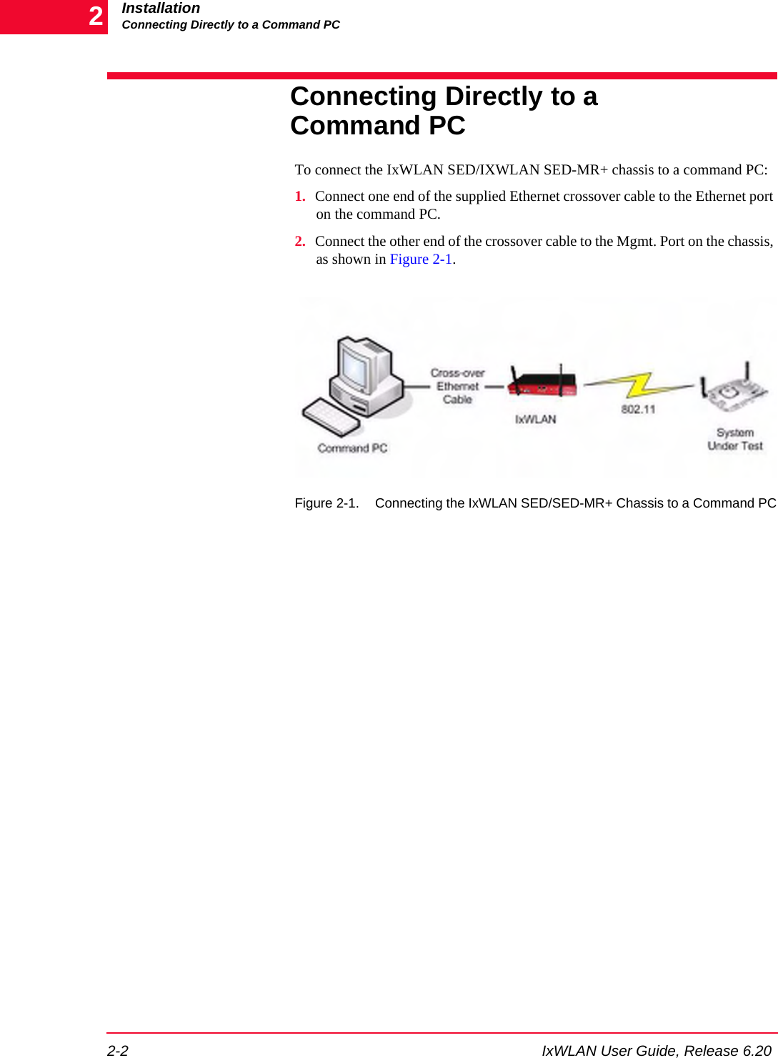
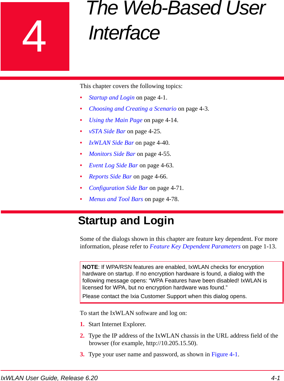
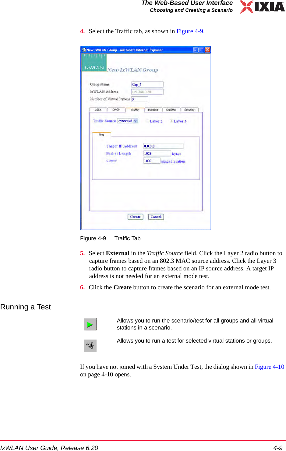
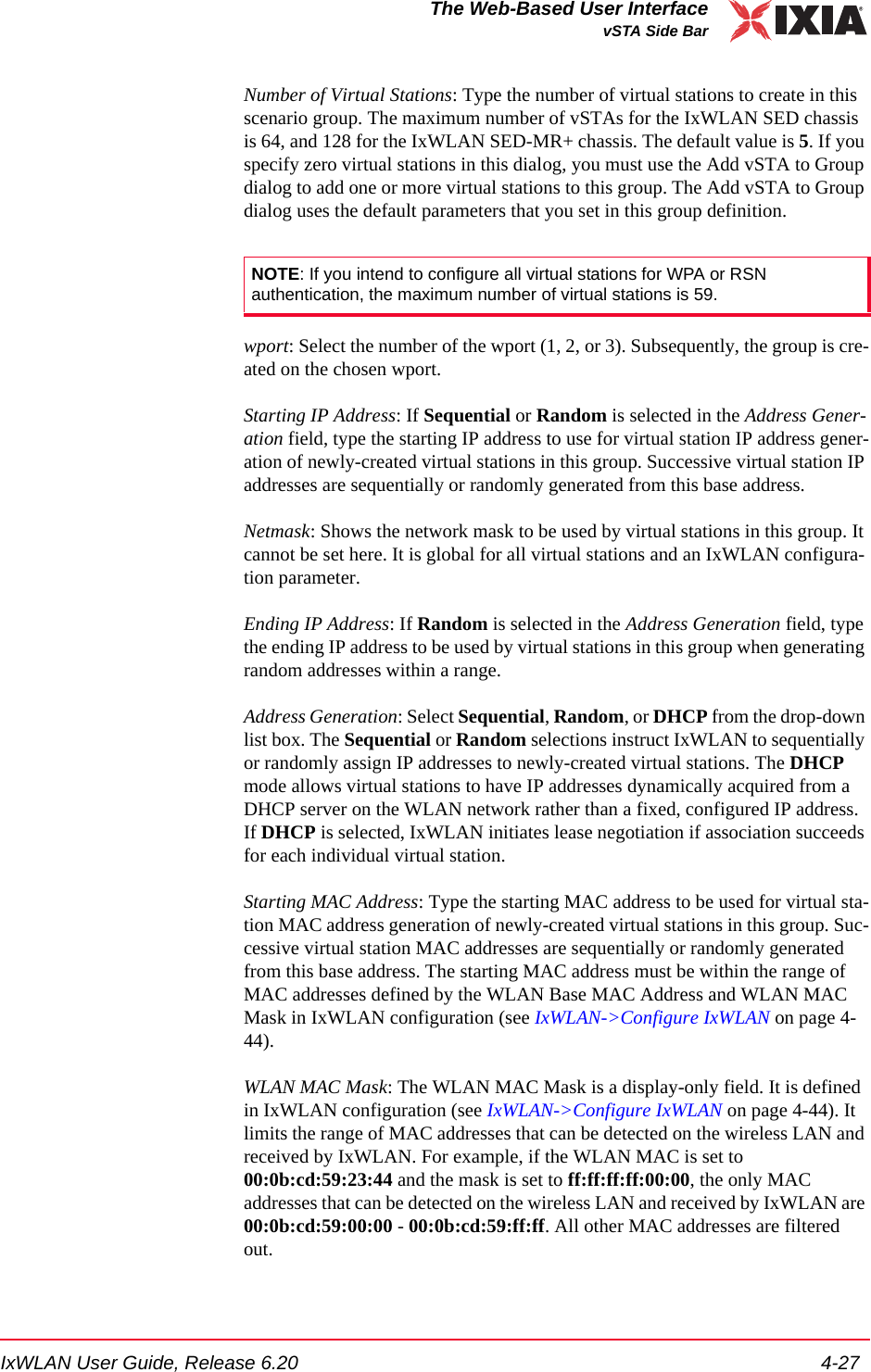
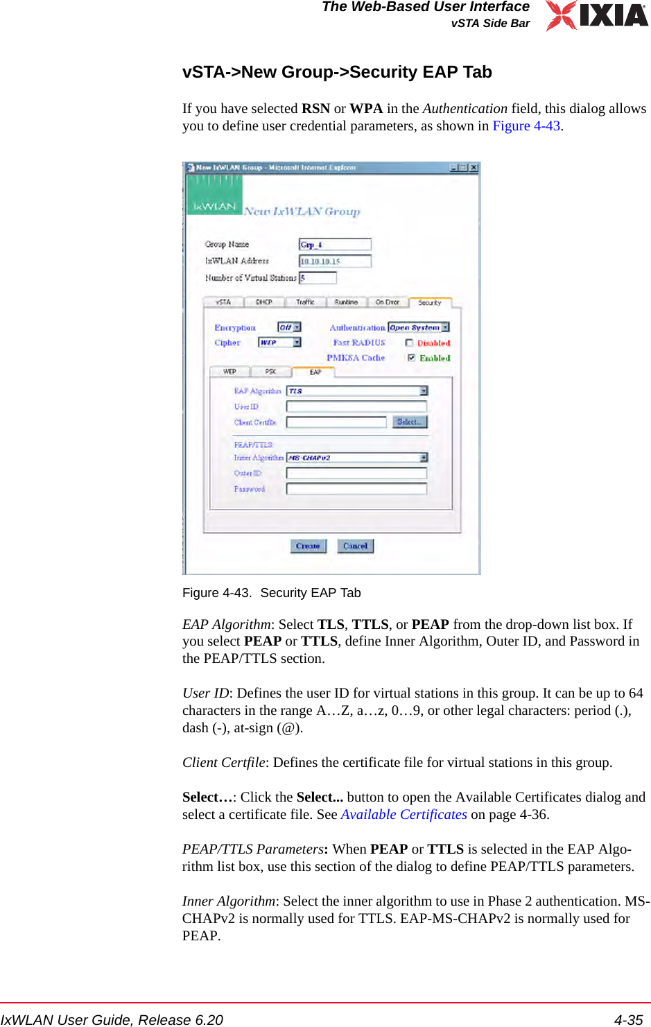
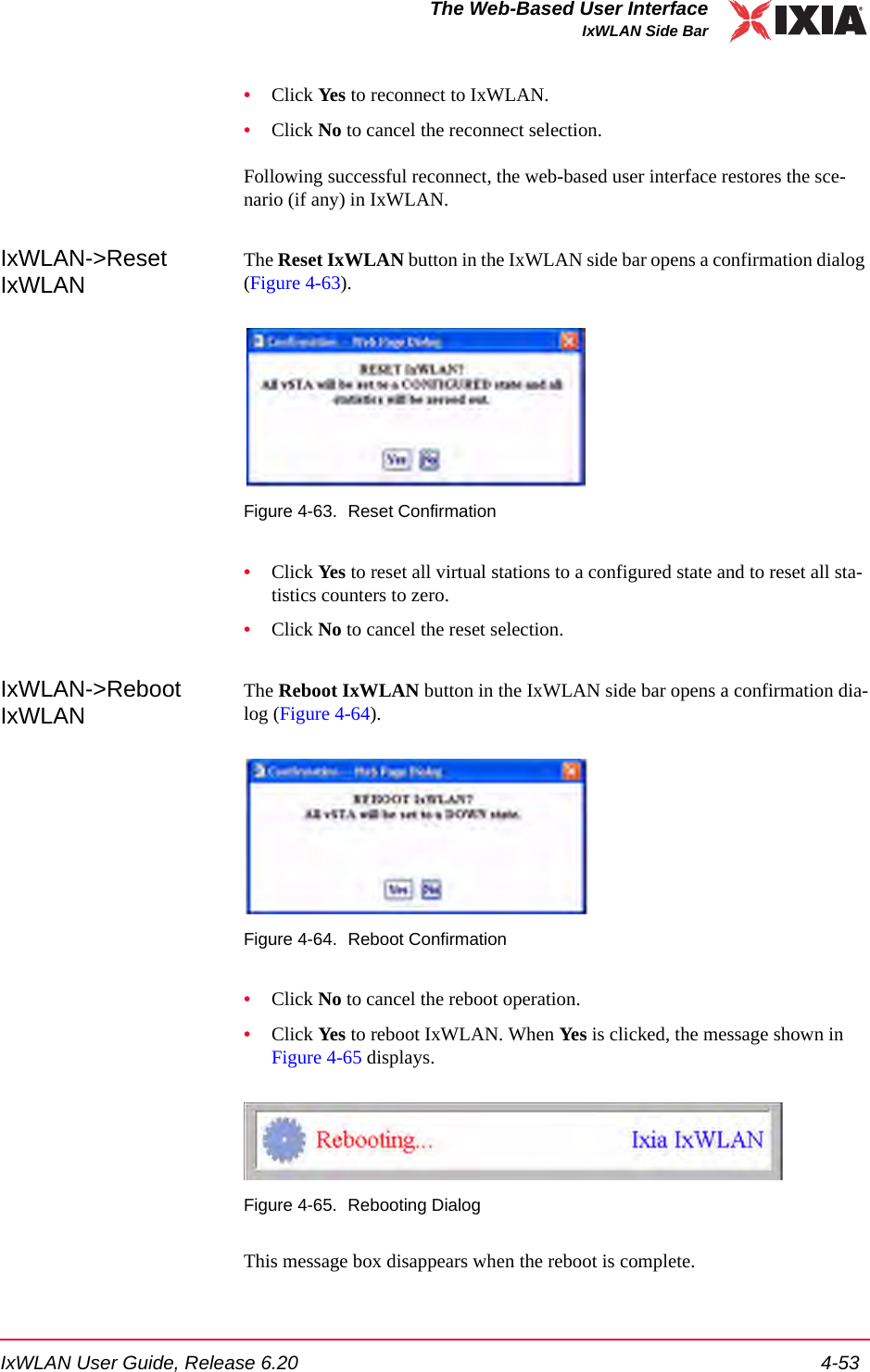
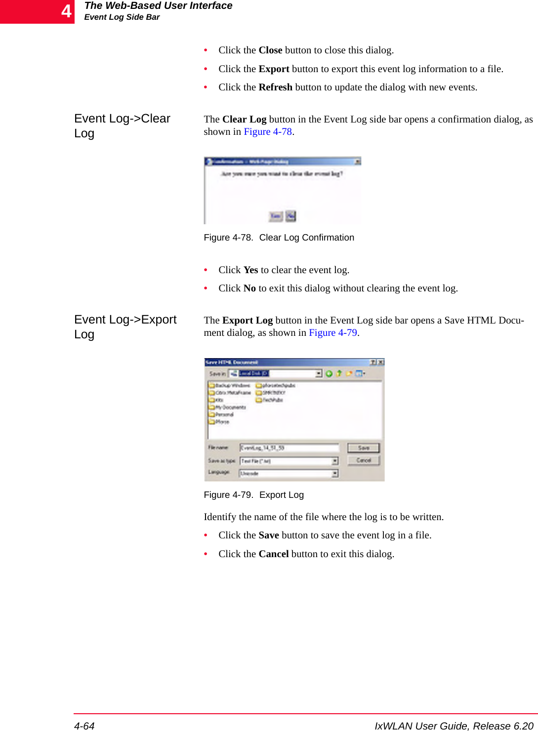
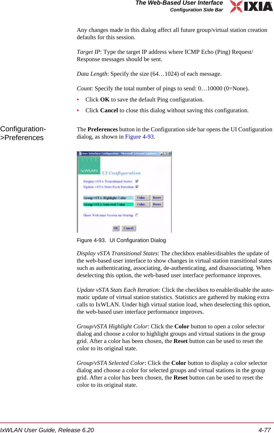
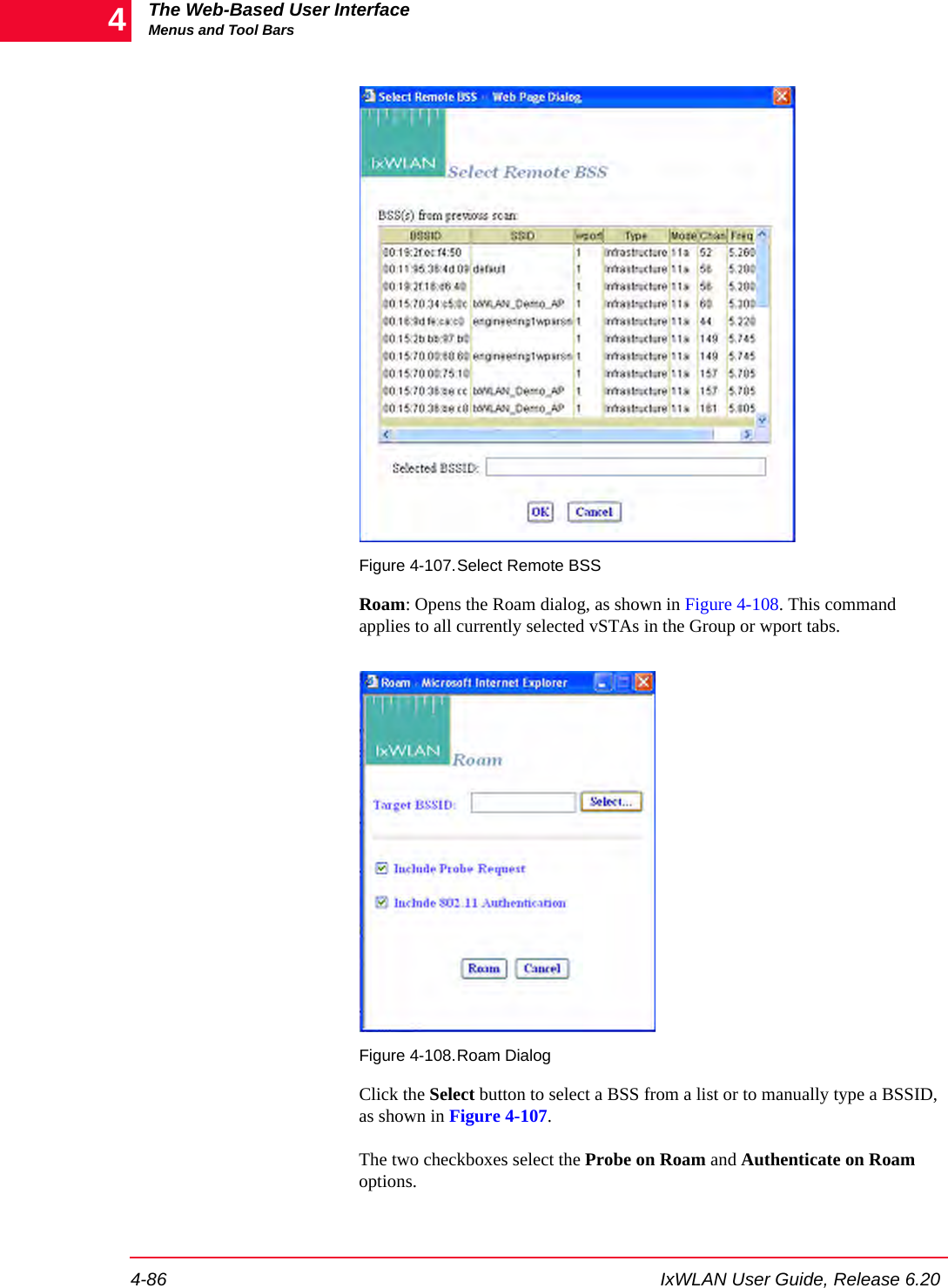
![IxWLAN User Guide, Release 6.20 1-15IntroductionFeature Key Dependent ParametersConfiguration->Security->EAP Tab: Inner AlgorithmNo equivalent MS-CHAPv2, EAP-MS-CHAPv2WPA/RSNConfiguration->Security->EAP Tab: Outer IDNo equivalent Outer Identity WPA/RSNConfiguration->Security->EAP Tab: PasswordNo equivalent Password WPA/RSNEvent Log->Configure Log->Modules Logset evlog modules WPA/RSN WPA/RSNNo equivalent get cryptocap show crypto hardware capabilitiesWPA/RSNNo equivalent cryptotest test crypto hardware capabilitiesWPA/RSNScenario menu->Roam button->Roamroam, auth, sendprobe ID WPA/RSNGroup menu->Roam button->Roamroam, auth, sendprobe ID WPA/RSNvSTA menu->Roam button->Roamroam, auth, sendprobe ID RSNvSTA menu->Pre-authenticate... button->802.11i Pre-Authenticationpreauth BSSID RSNScenario menu->Pre-authenticate... button->802.11i Pre-Authenticationpreauth BSSID RSNGroup menu->Pre-authenticate... button->802.11i Pre-Authenticationpreauth BSSID WPA/RSNNew IxWLAN Group>Runtime tab->Roam Type autoconf [roamtype] Disassociation/ ReassociationWPA/RSNEdit IxWLAN Group>Runtime tab->Roam Type autoconf [roamtype] Disassociation/ ReassociationWPA/RSNAdd vSTA to Group>Runtime tab->Roam Type autoconf [roamtype] Disassociation/ ReassociationWPA/RSNConfig IxWLAN>IxWLAN->Radio ->Scan at Boot Modeget bootscan, setbootscan Enabled/ Disabled/All Modes802.11 a/ b/ gConfig IxWLAN>IxWLAN->Radio ->Background Joinget bkjoin, set bkjoin Enabled/ Disabled 802.11 a/ b/ gTable 1-5. Feature Key Dependent Parameters (Continued)Web-Based User Interface Fields CLI Commands Feature Key Dependent Parameters Needed Feature Key](https://usermanual.wiki/Ixia/GC617644.User-Manual-1/User-Guide-827937-Page-23.png)
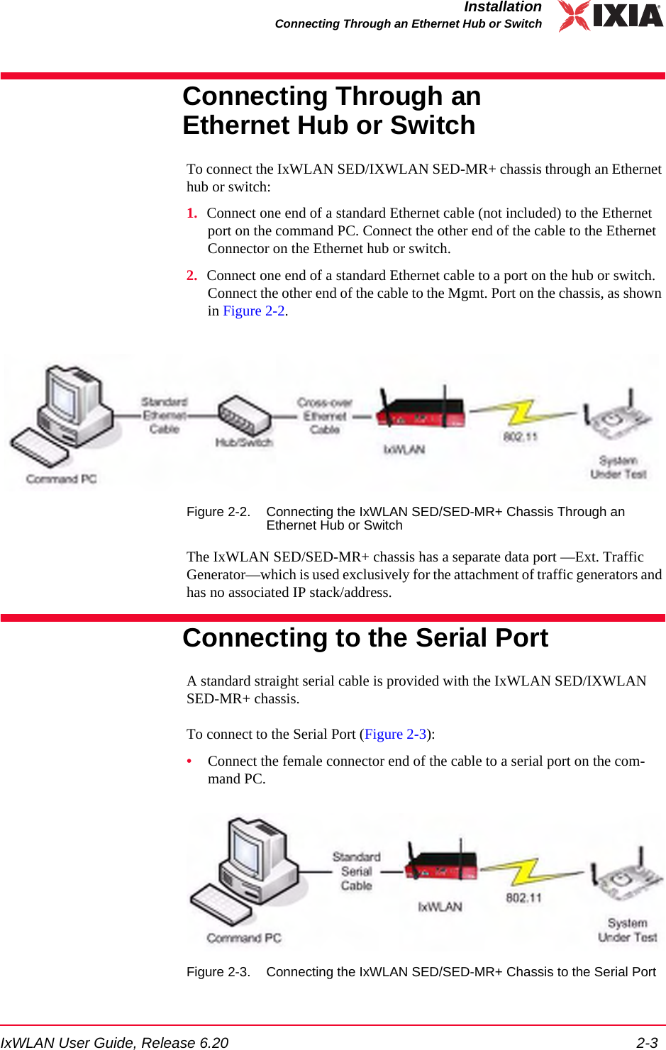


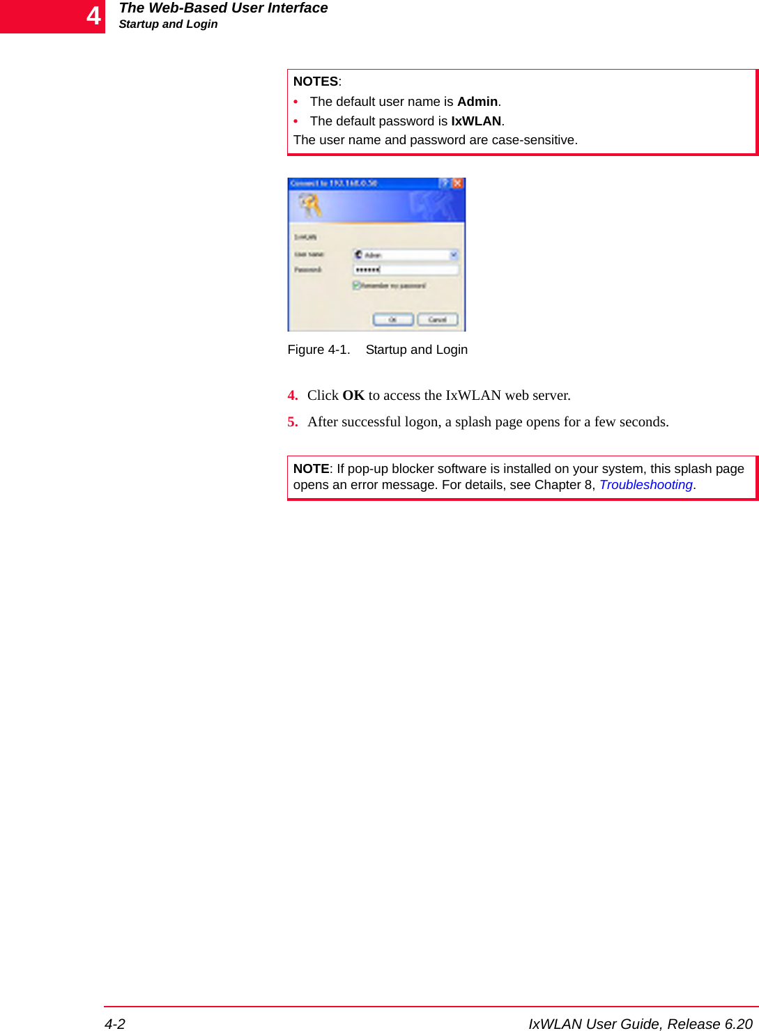
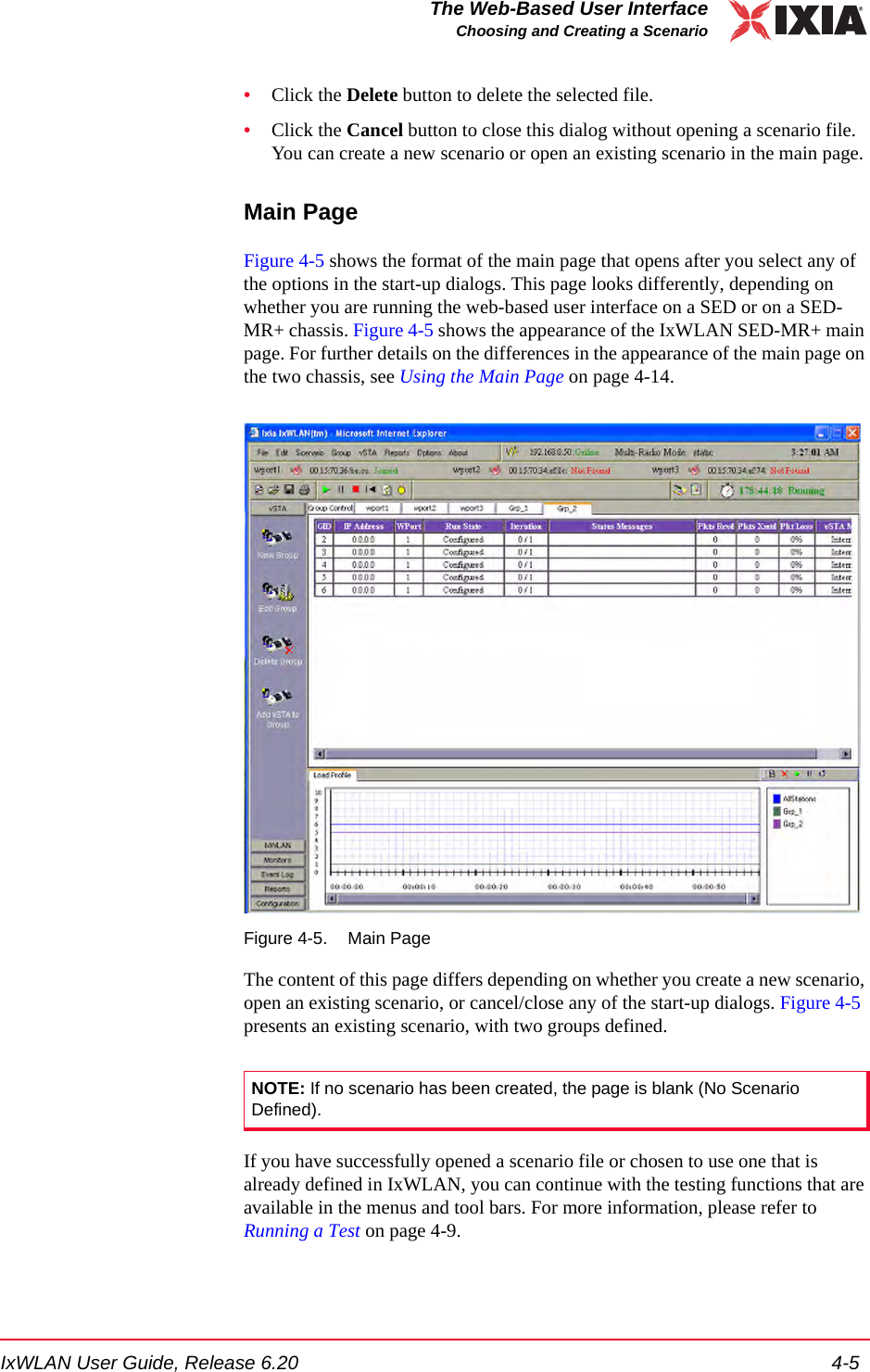
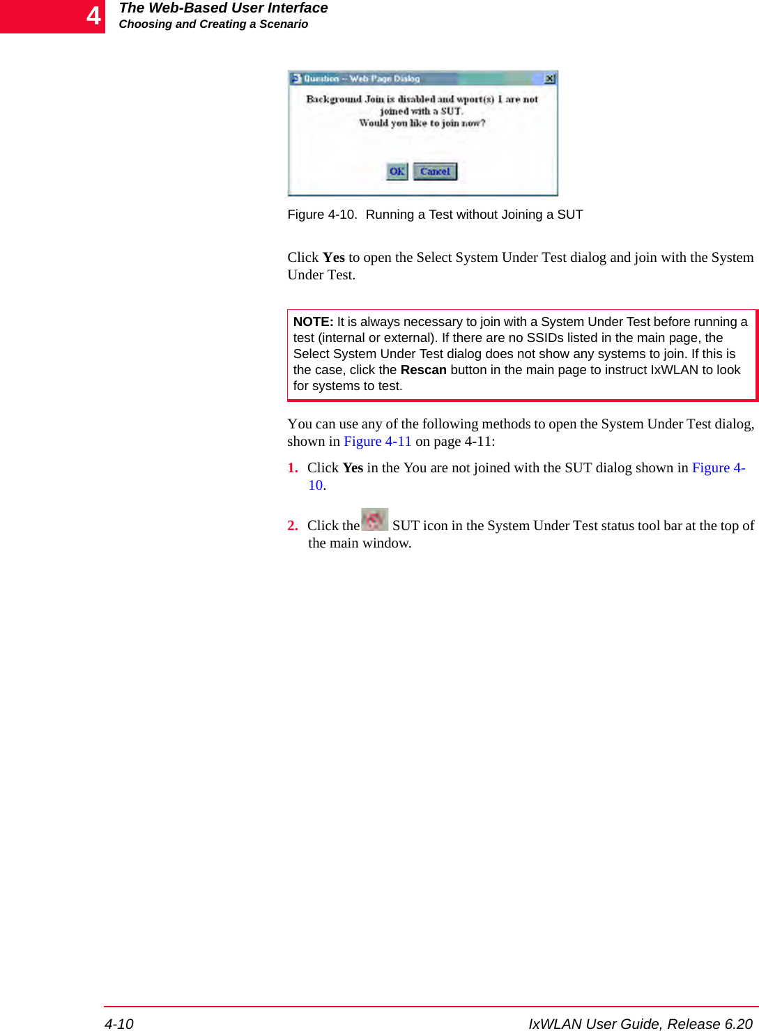
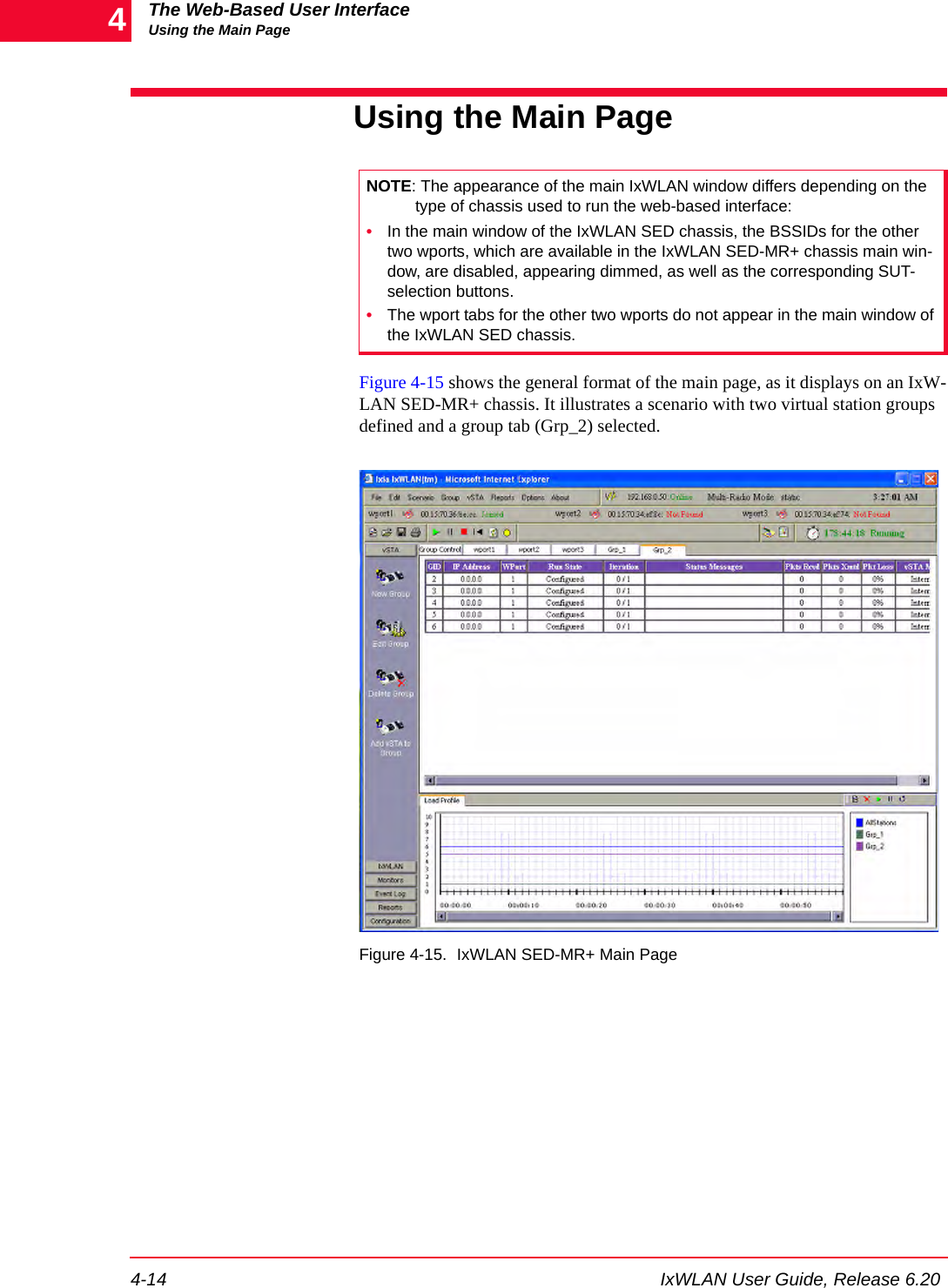

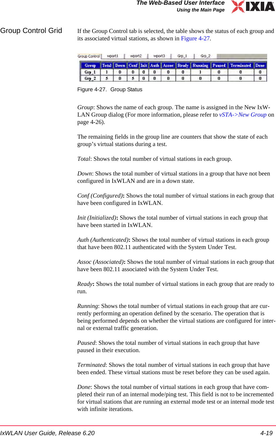
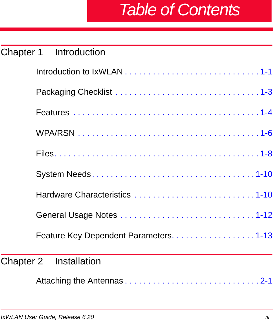
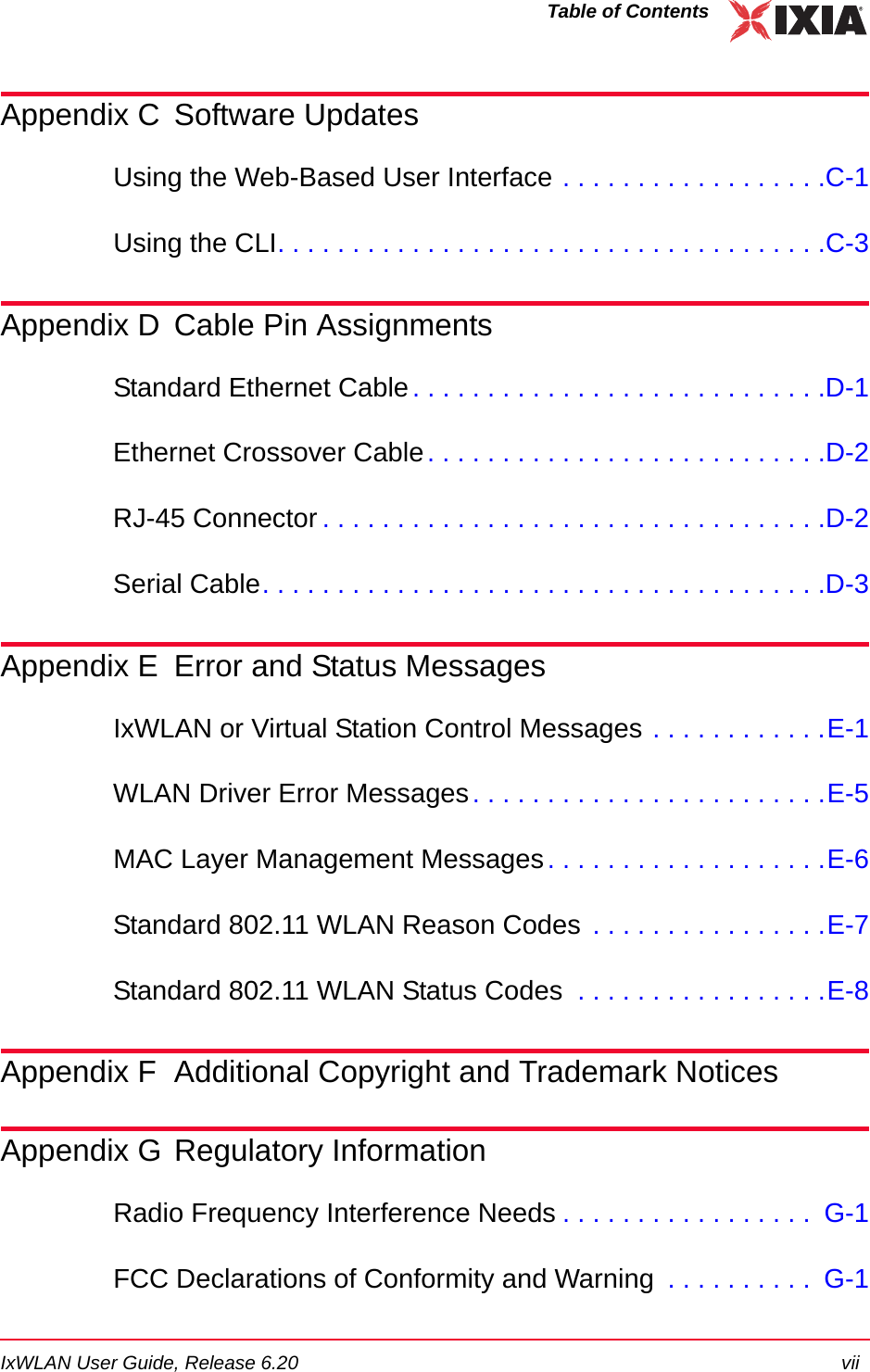
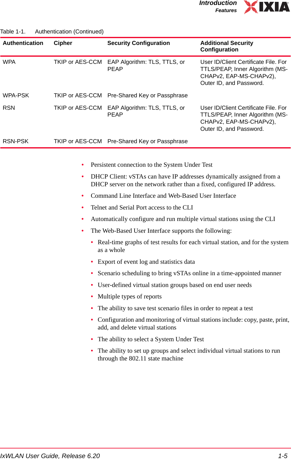
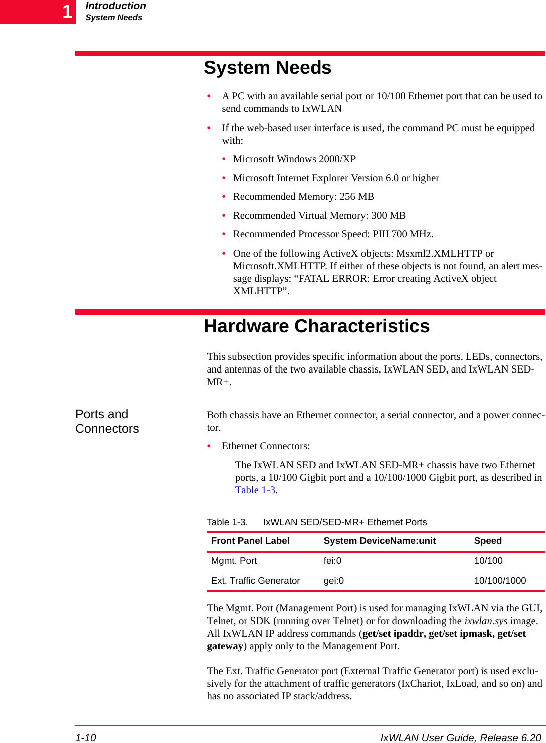
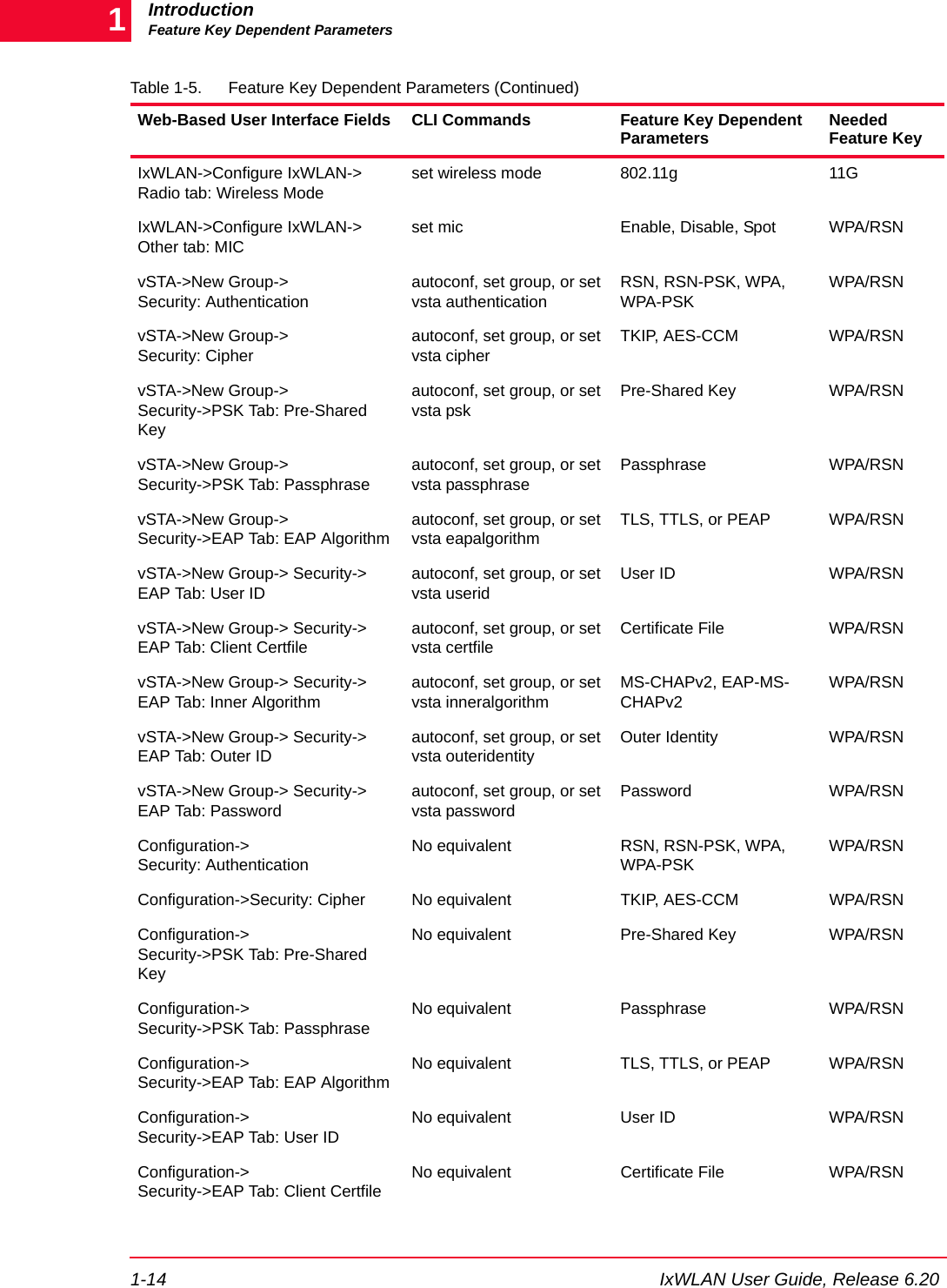
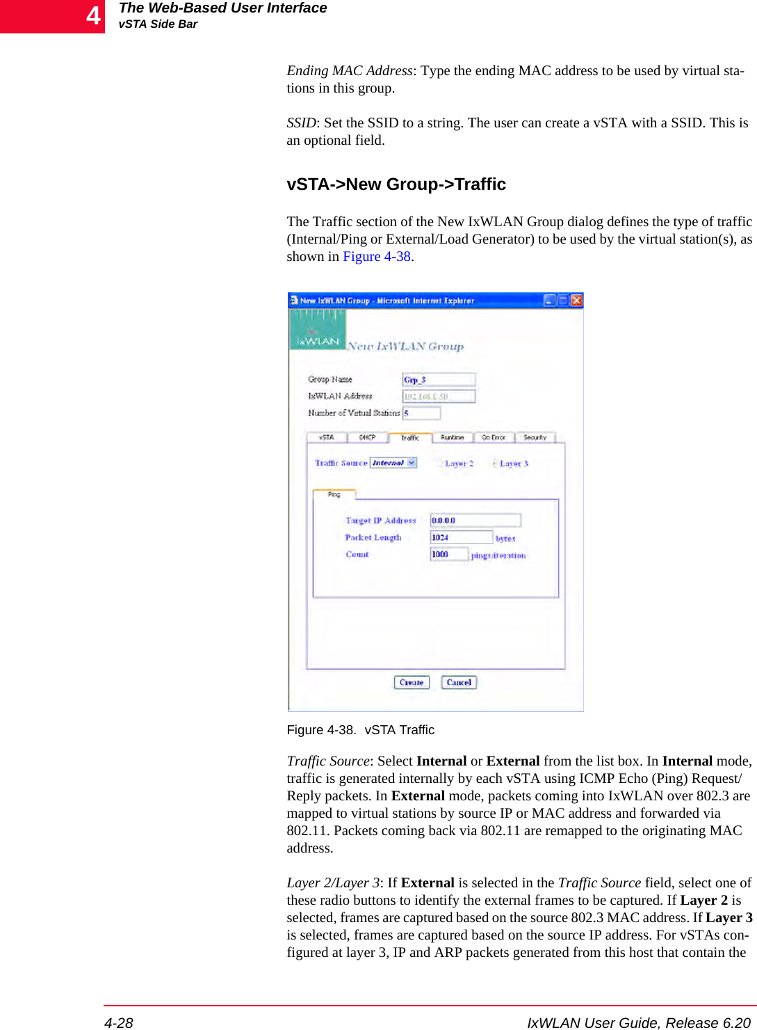
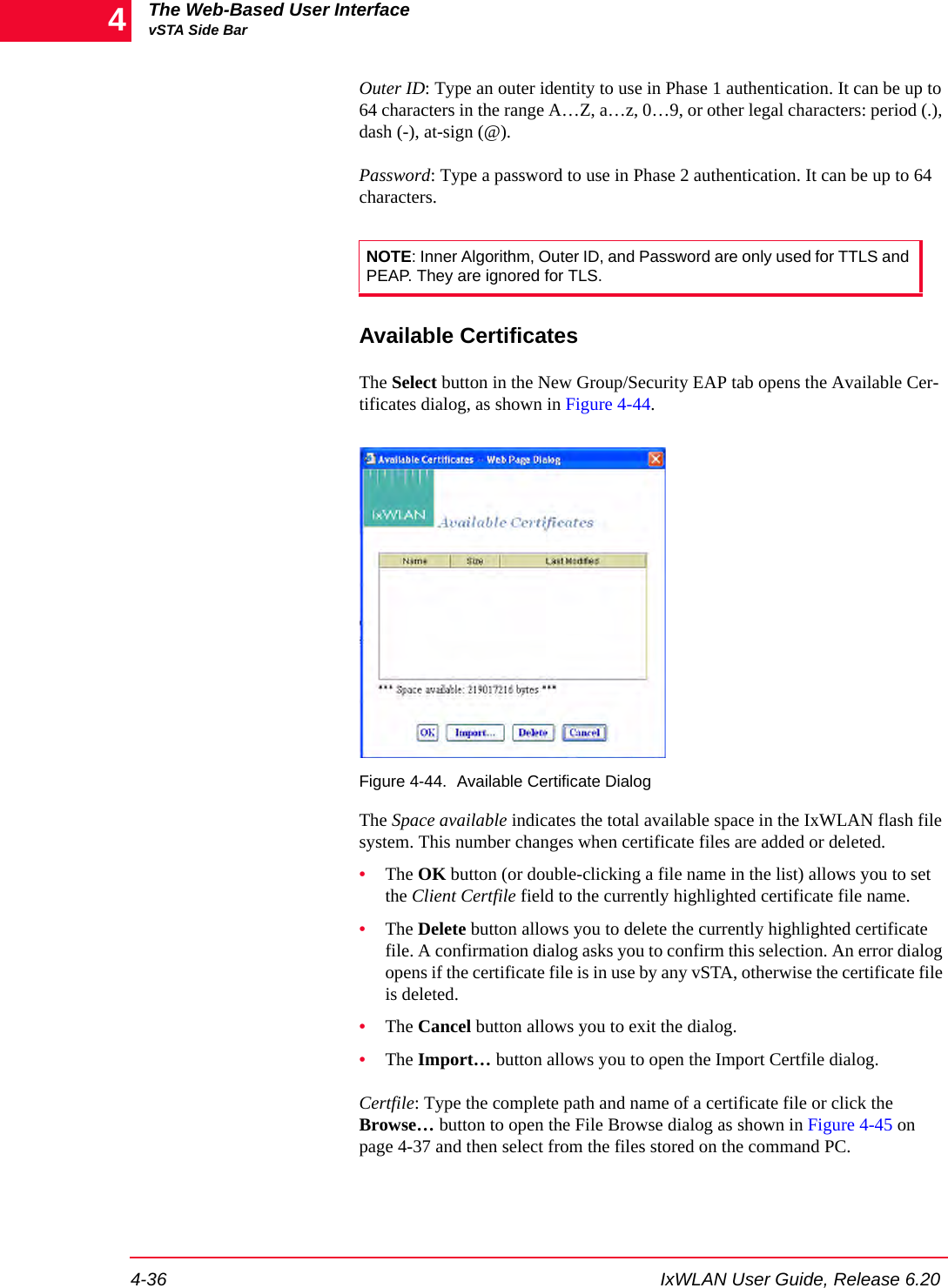
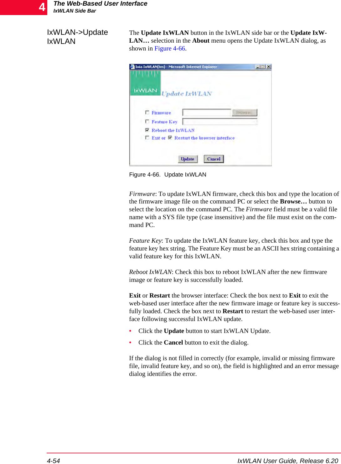
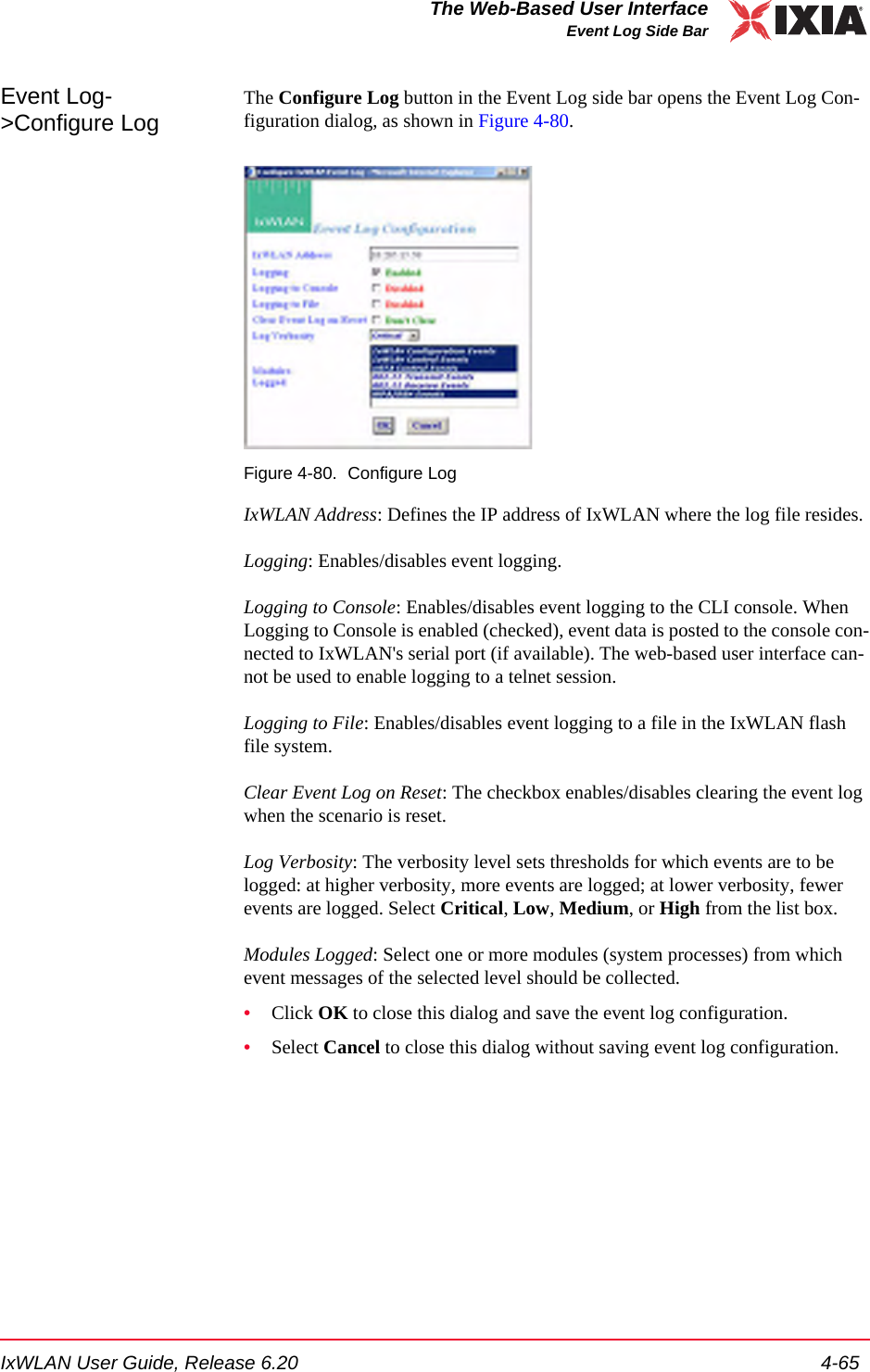
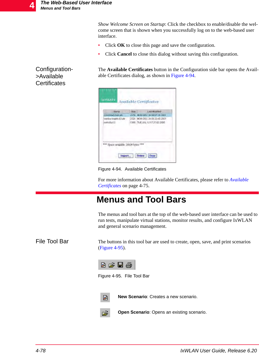
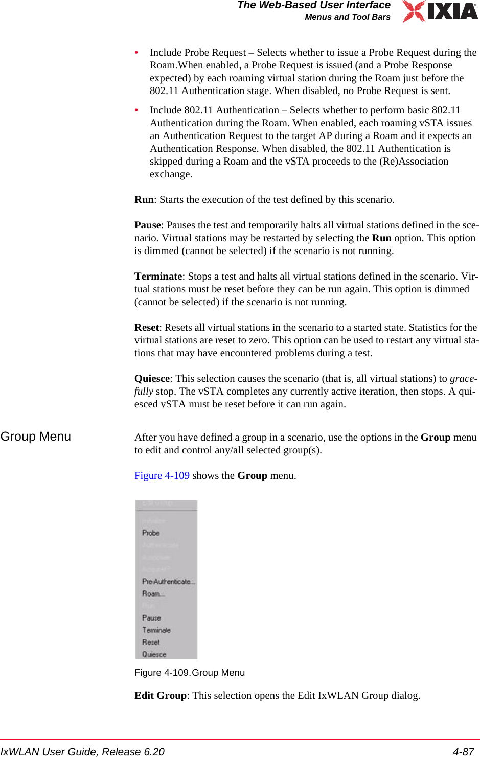
![IxWLAN User Guide, Release 6.20 4-21The Web-Based User InterfaceUsing the Main PageYou can select one or more line items/virtual stations in the table and choose a menu item or tool bar button to execute a command for an individual or multiple virtual stations. You can double-click a virtual station line item in the table to open the Edit Vir-tual Station dialog. For more information about this dialog, please refer to vSTA->Add New vSTA to Group on page 4-39.You can right-click the selected virtual stations to open the vSTA menu. For more information about the selections in this menu, please refer to vSTA Menu on page 4-89.Group Tab Columns: Within a group, you can double-click the table heading to configure the displayed columns, as shown in Figure 4-29.Figure 4-29. Group Tab ColumnsSelect one or more items in the All Columns list box and click the [>>] button to move them to the Selected Columns list box. Click the Modify button to add the columns to the group table. Click the Reset button to return the columns to their default setting.Load Profile The Load Profile section of the page can be used to automatically execute scenar-ios at scheduled intervals, as shown in Figure 4-30 on page 4-22.](https://usermanual.wiki/Ixia/GC617644.User-Manual-1/User-Guide-827937-Page-57.png)
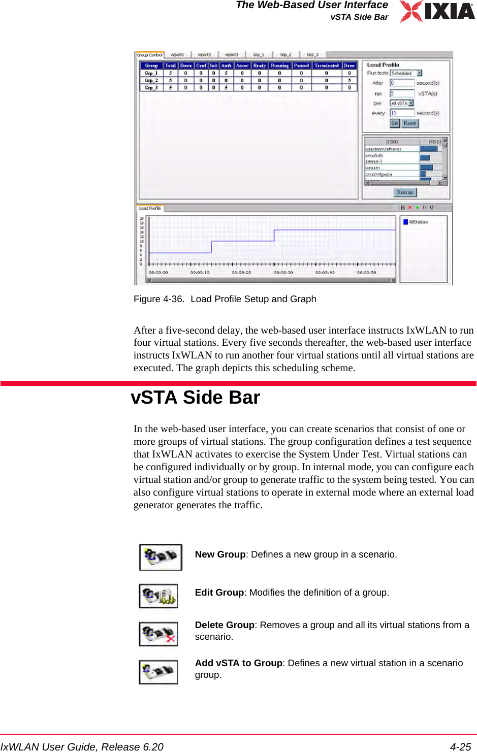
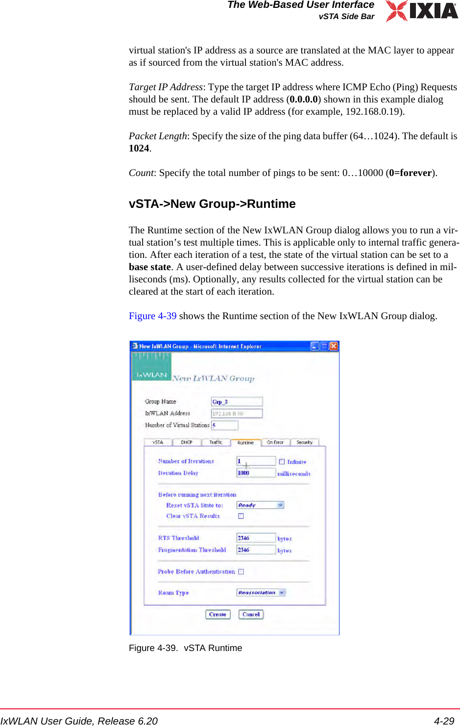

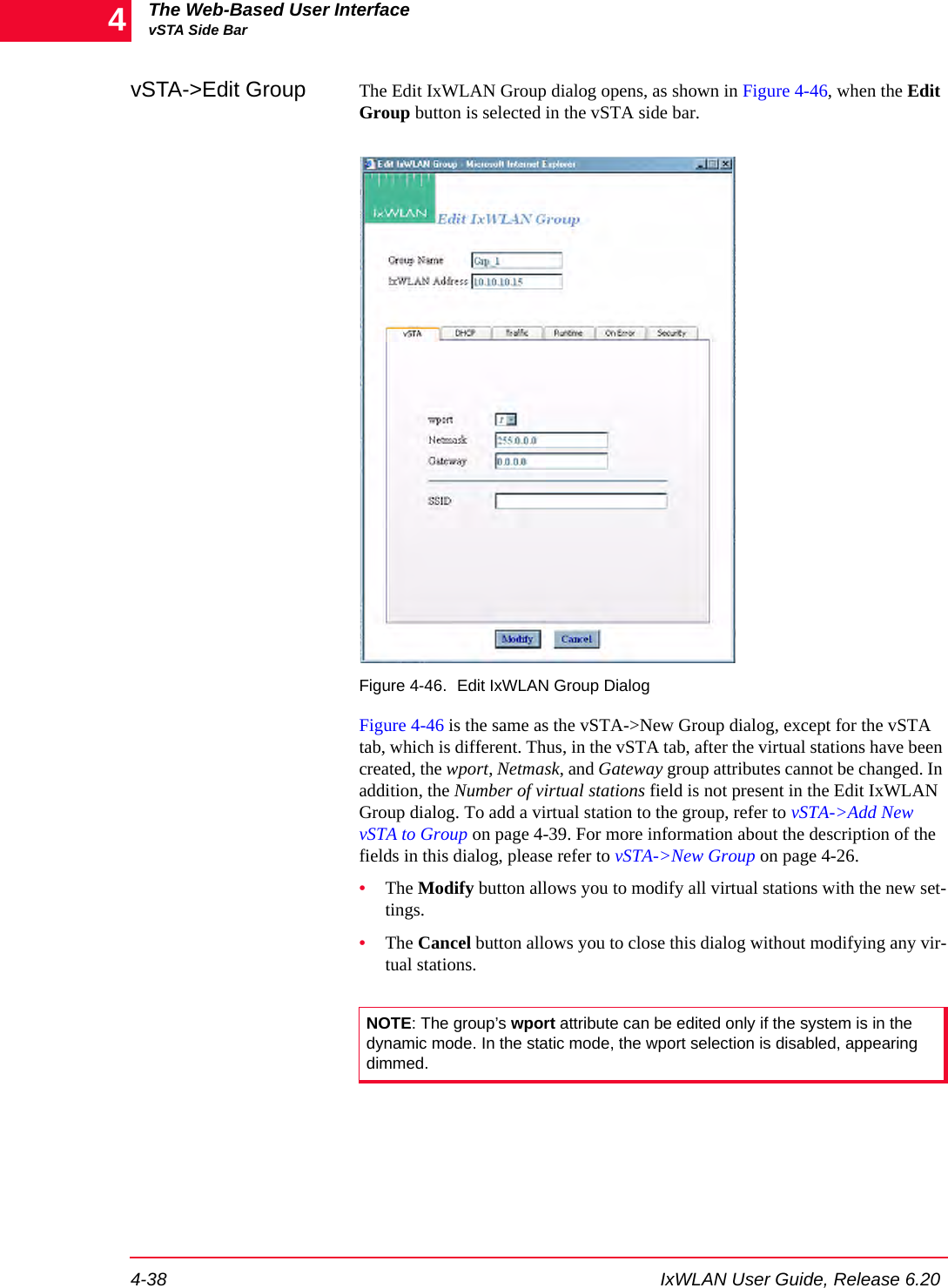

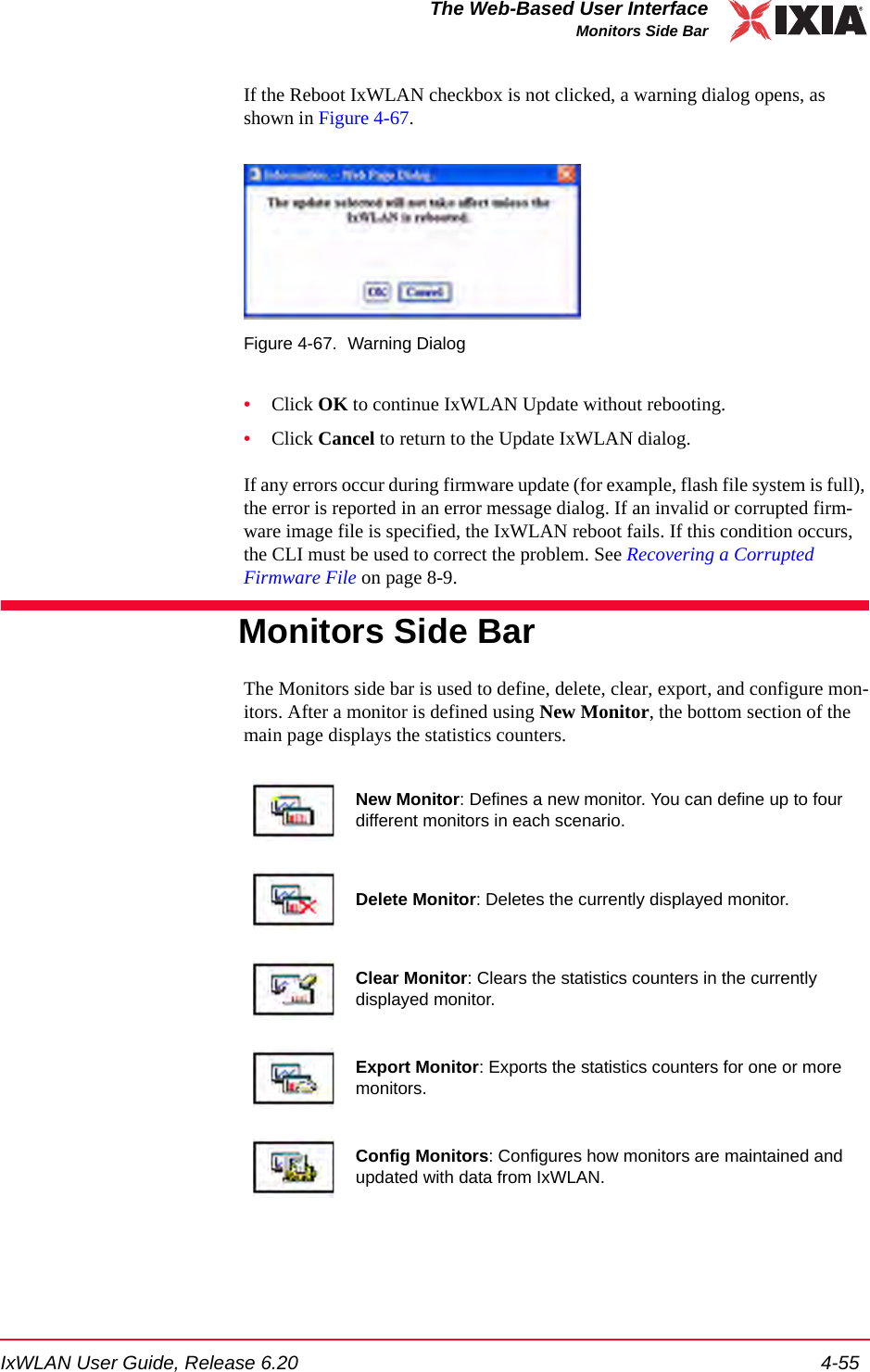
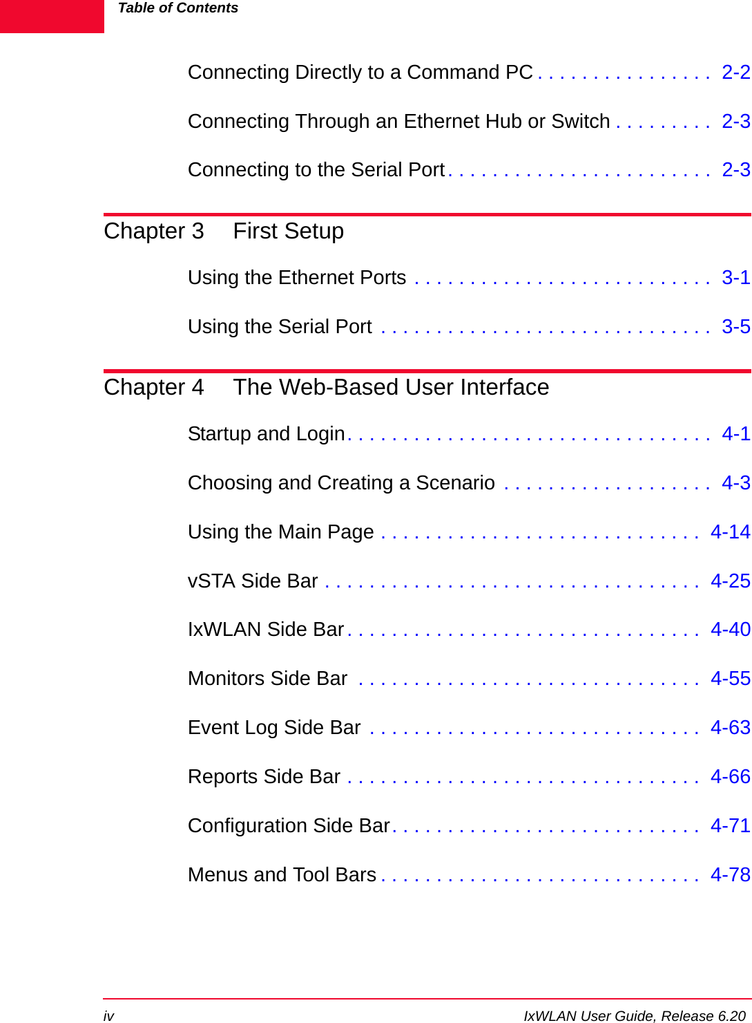
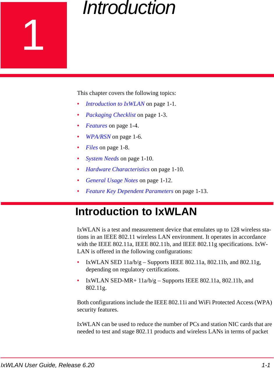
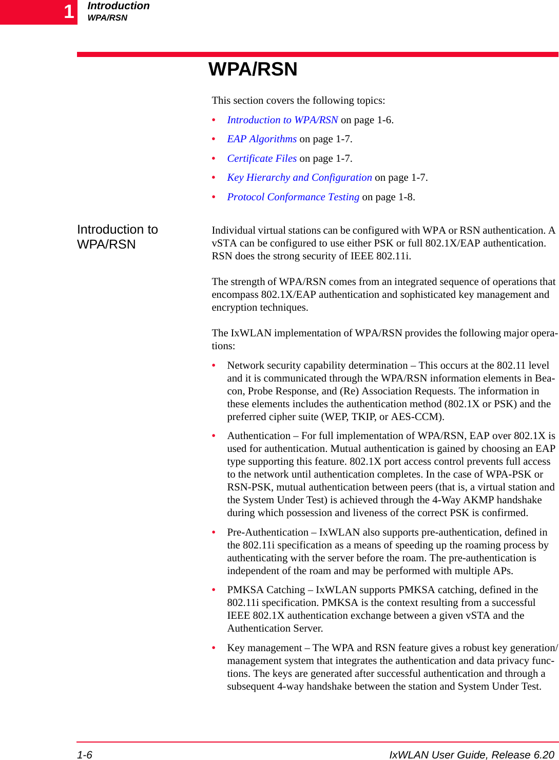
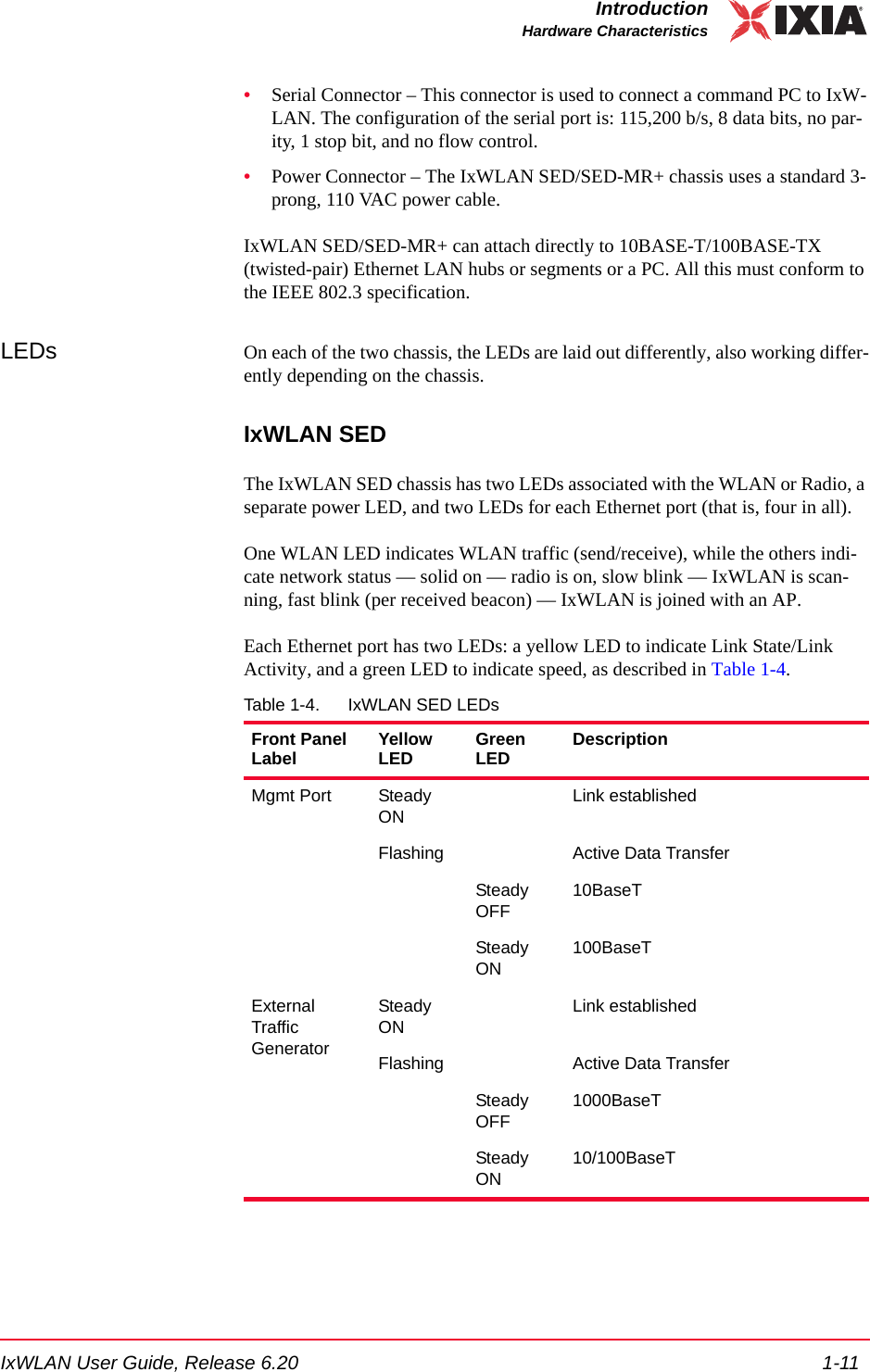
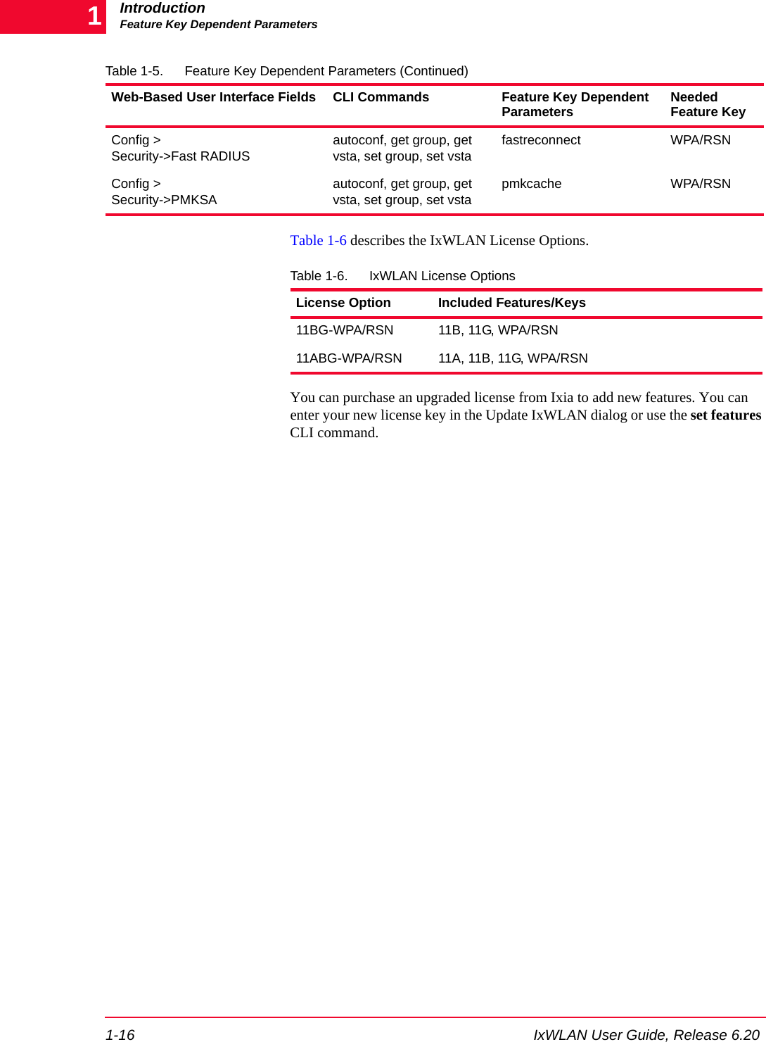
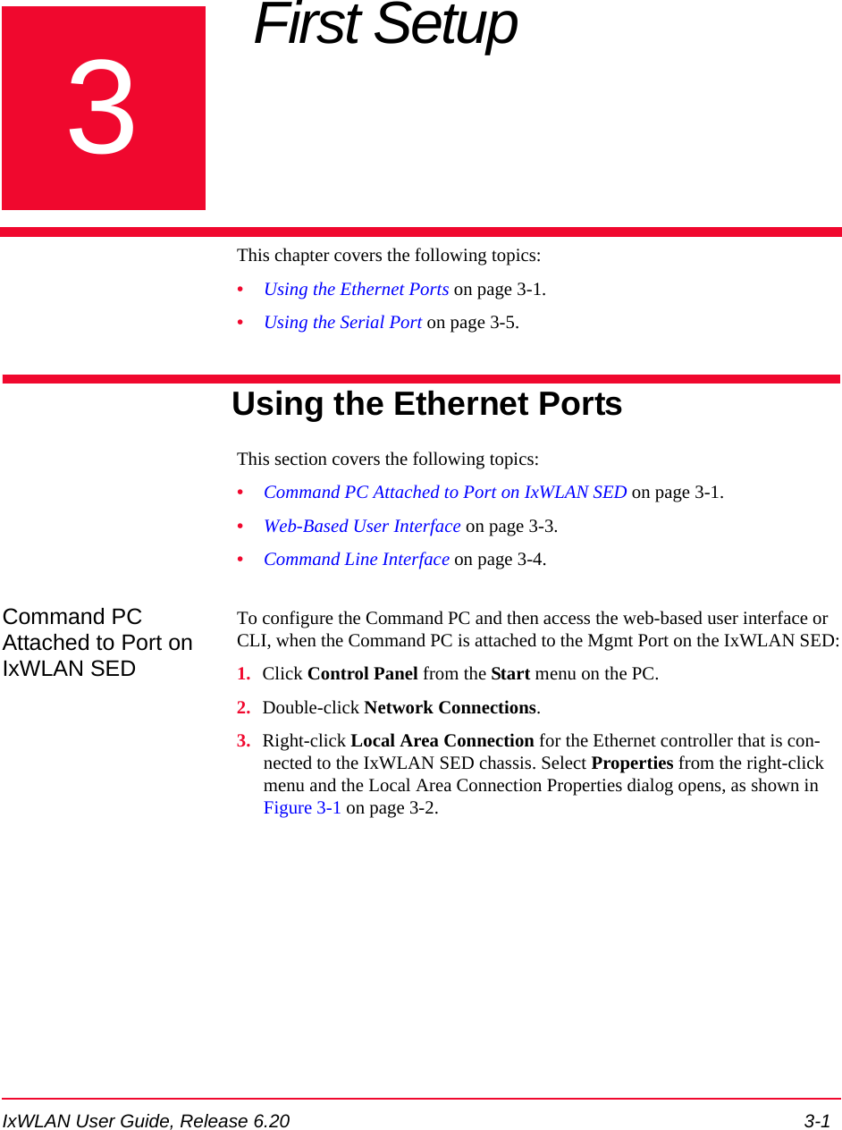
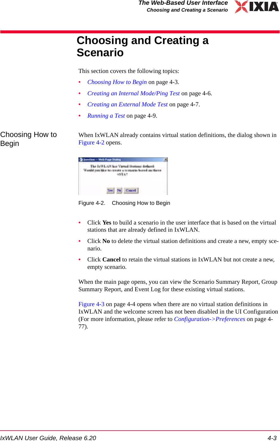
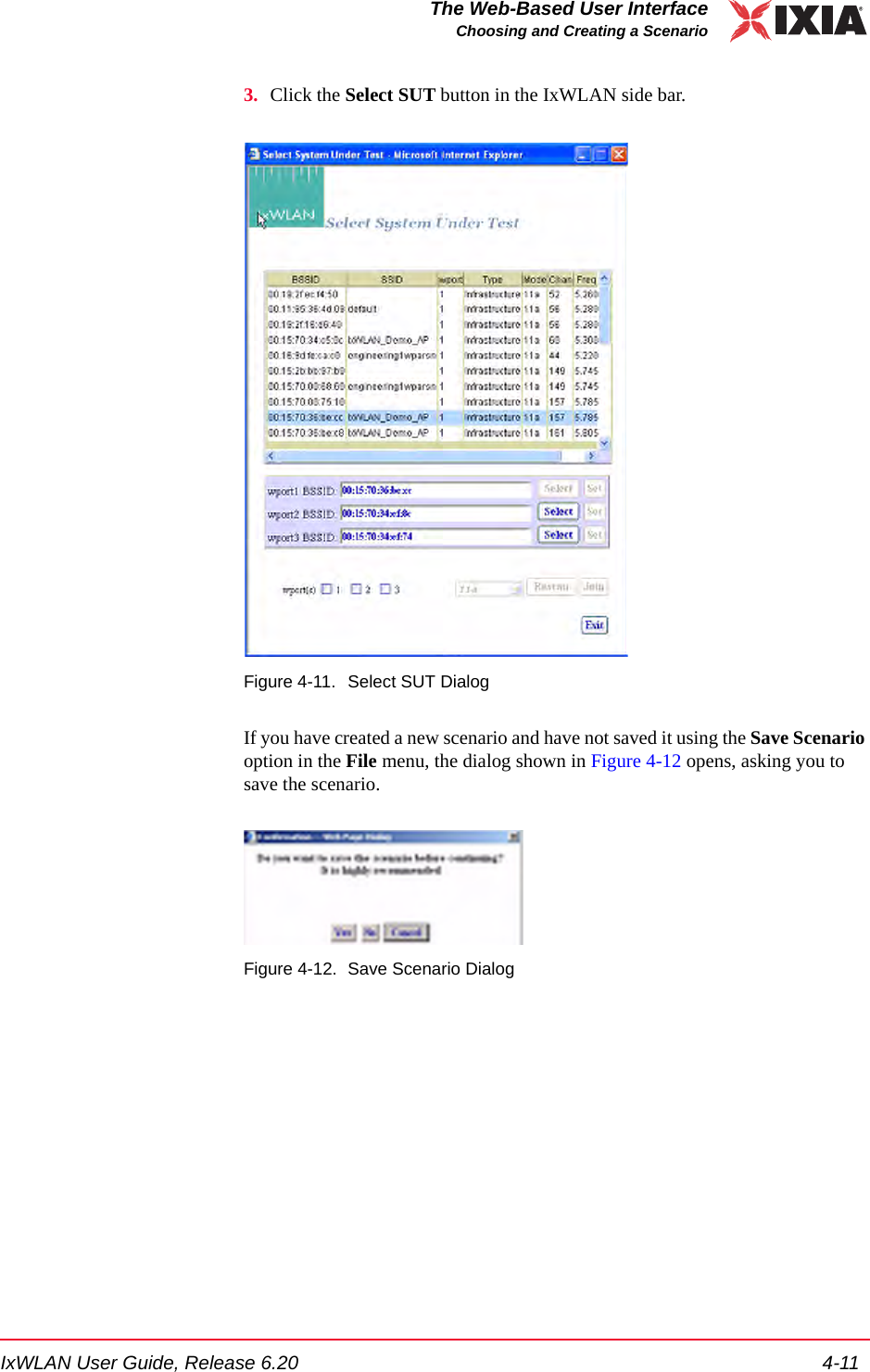
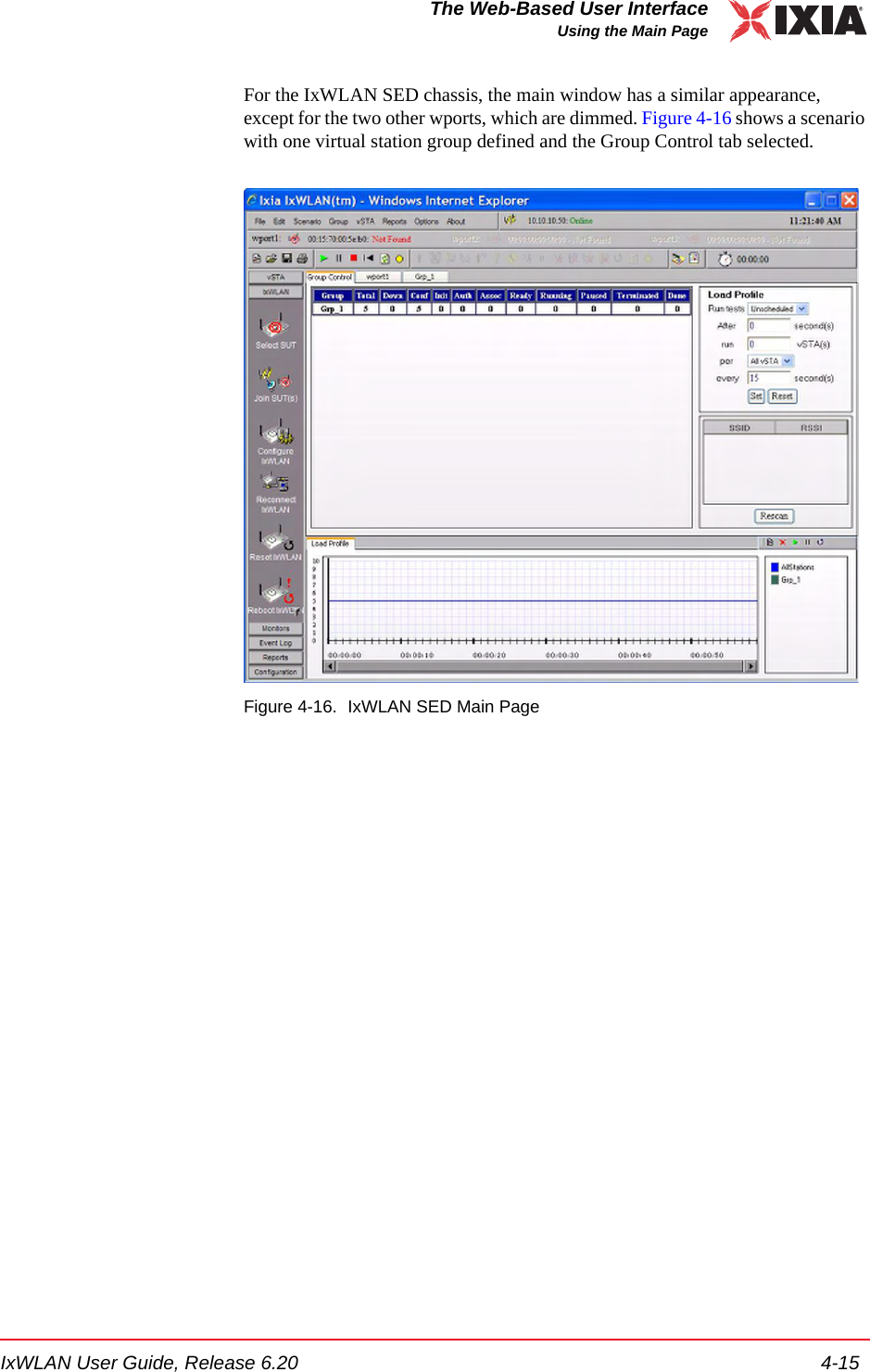
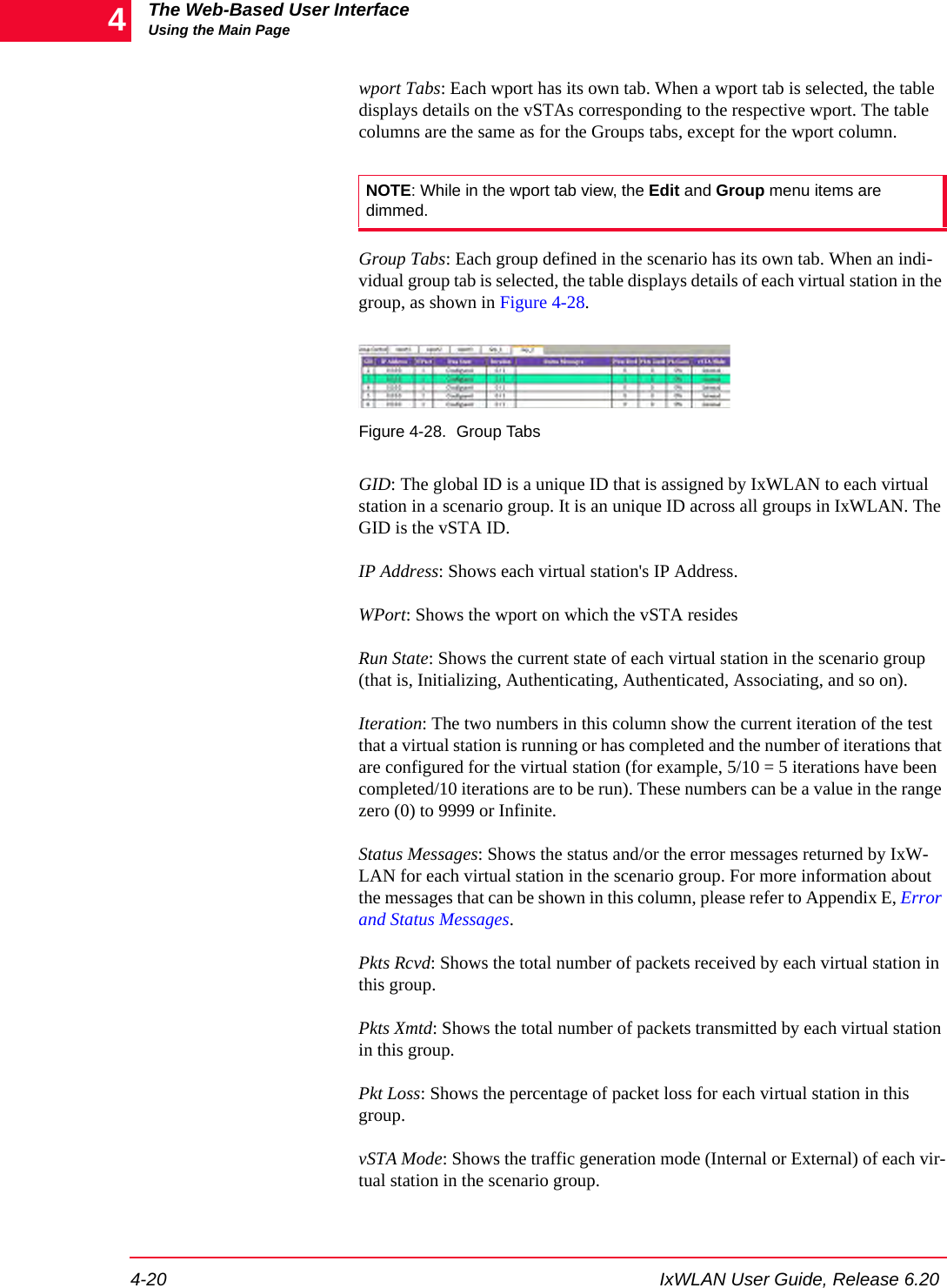
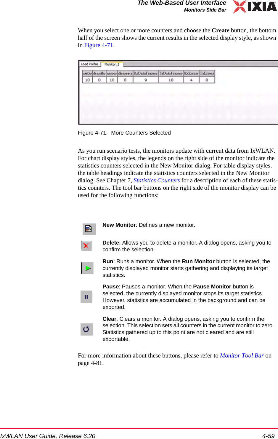
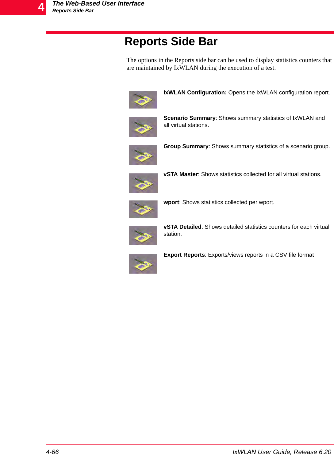
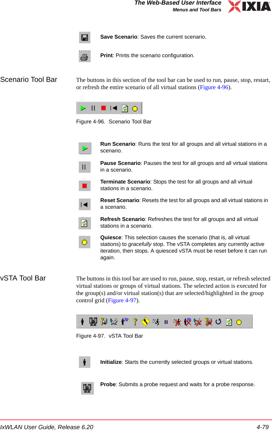
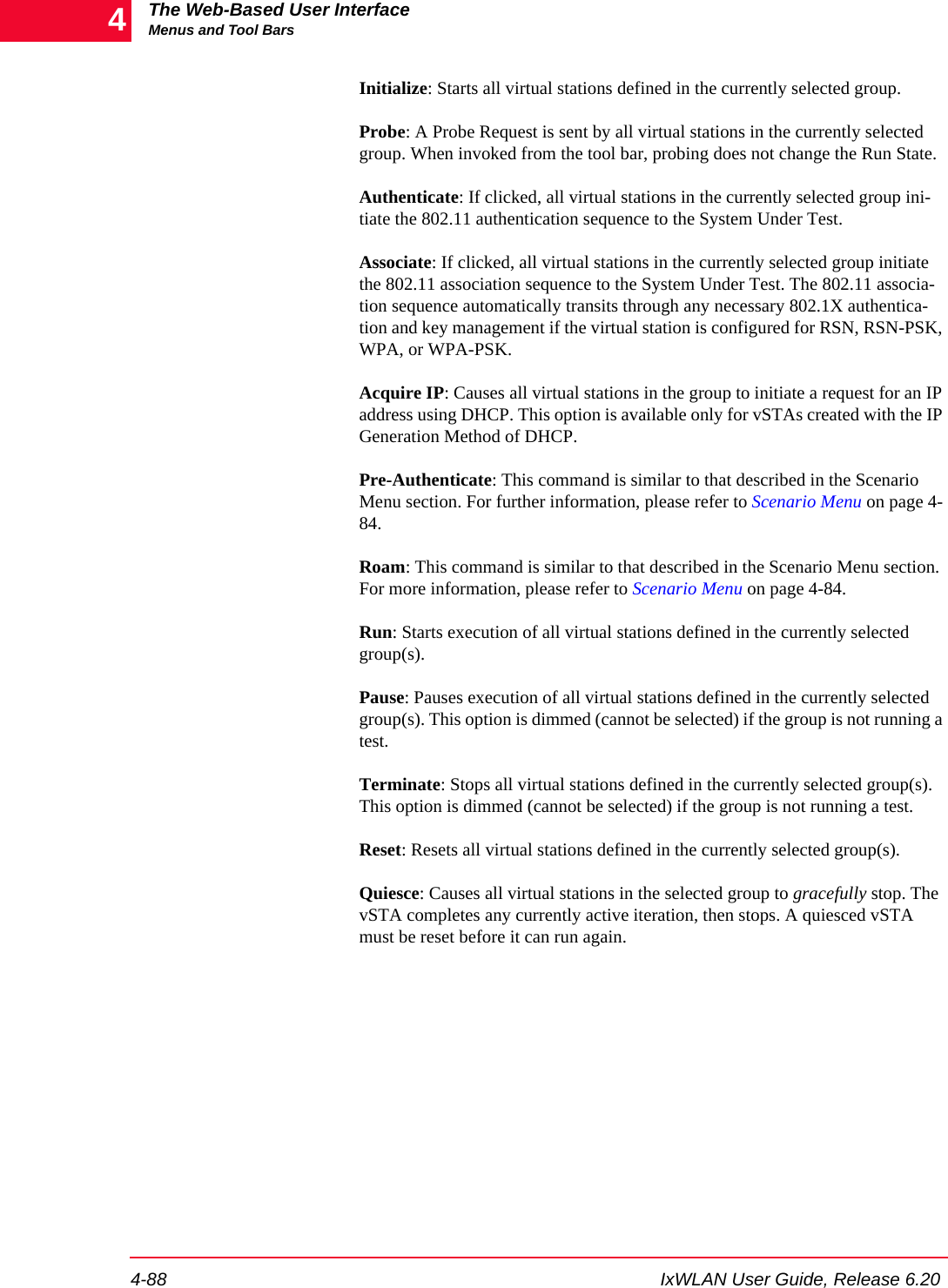
![IxWLAN User Guide, Release 6.20 4-57The Web-Based User InterfaceMonitors Side BarDisplay Style: Select a display style from the list box. It can be one of the follow-ing: Line Graph, Bar Graph, or Table.Monitors->Selected Monitors: Select one of the monitors to be maintained. Use the [>>] button (or double-click the line item) to transfer the predefined monitor to the Selected Monitors column. See Chapter 7, Statistics Counters for a description of each of these statistics counters.•Click the Create button to create and display the monitor.•Click the Cancel button to close this dialog.Monitors->New Monitor->SummaryUse the Summary section of the Define New Monitor dialog to select summary statistics counters, as shown in Figure 4-69.Figure 4-69. SummarySummary Counters->Selected Counters: Select one or more of the counters to be maintained in the test results file. Use the [>>] button to transfer the counters to the Selected Counters column. See Chapter 7, Statistics Counters for a descrip-tion of each of these statistics counters.•Click the Create button to create and display the monitor.•Click the Cancel button to close this dialog.](https://usermanual.wiki/Ixia/GC617644.User-Manual-1/User-Guide-827937-Page-93.png)
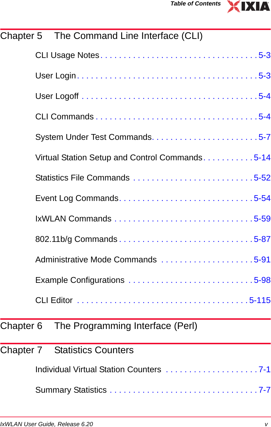
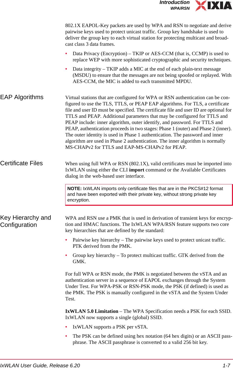
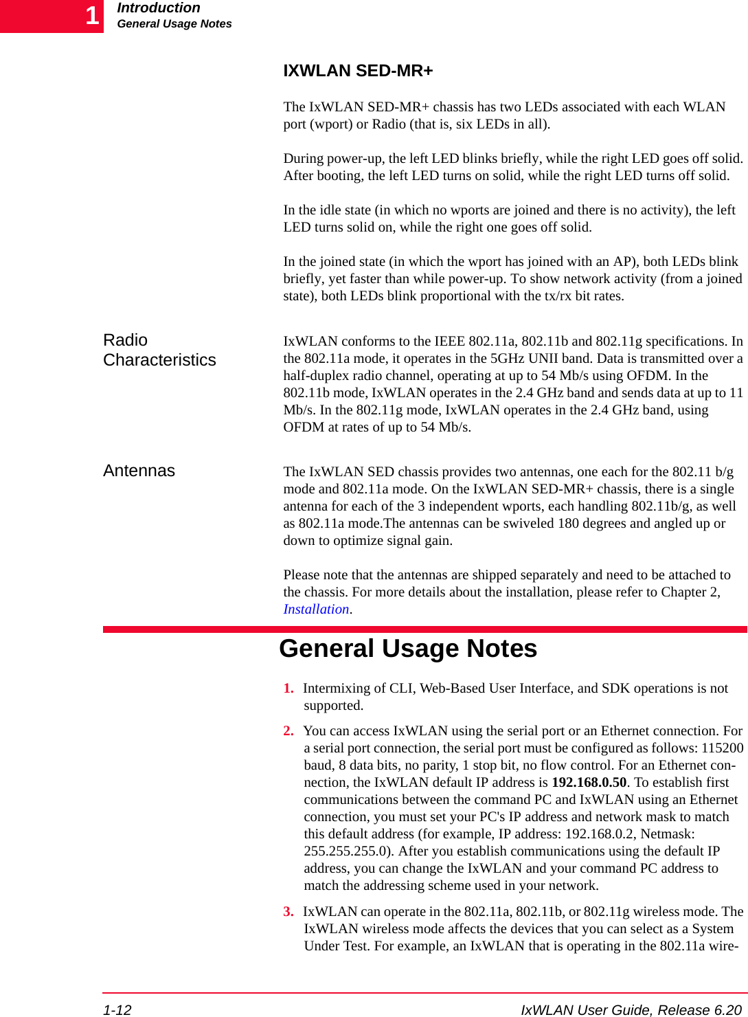
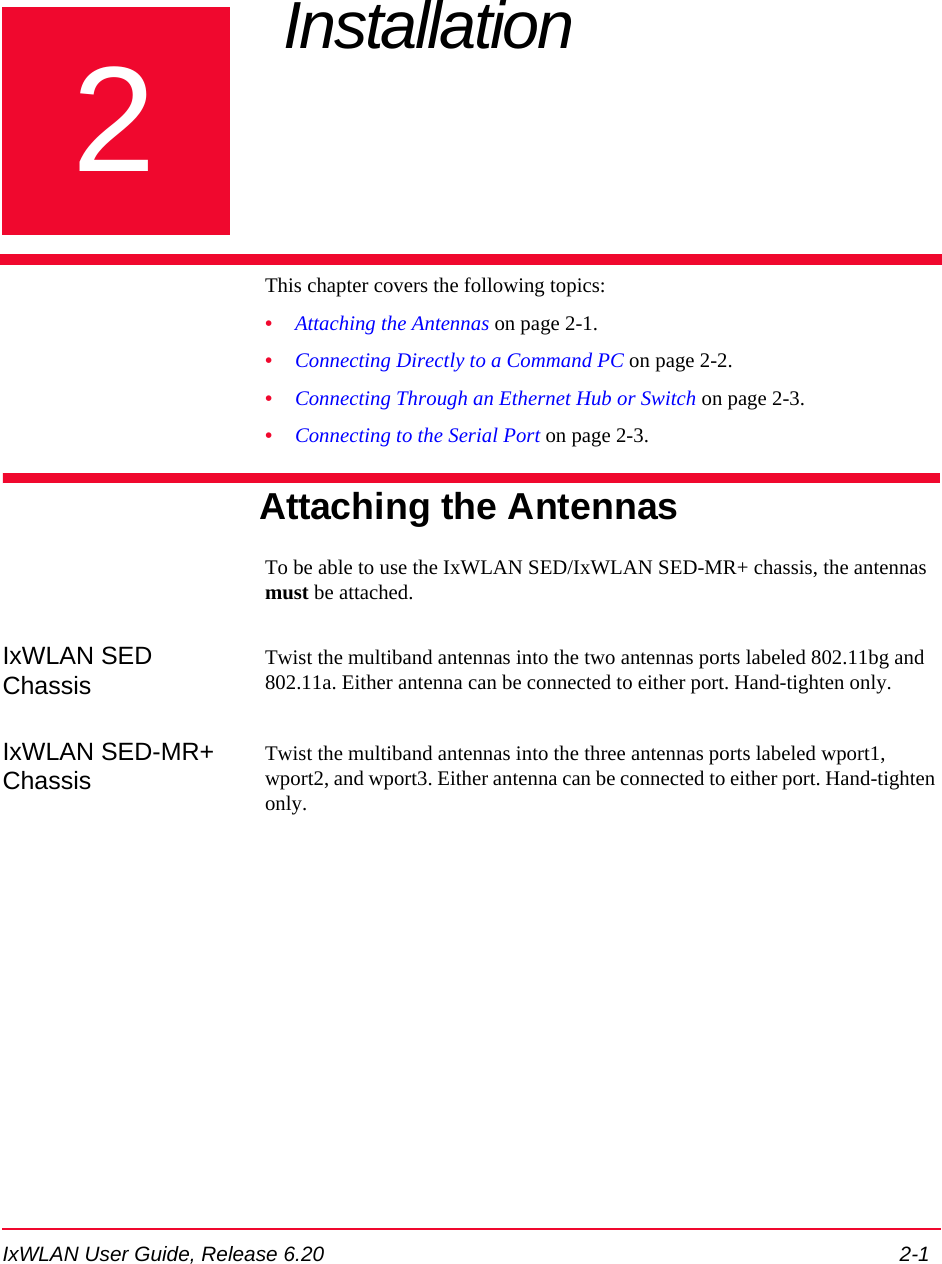
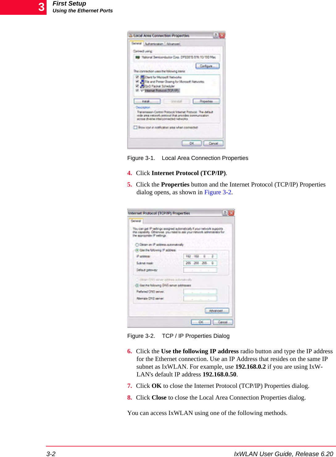
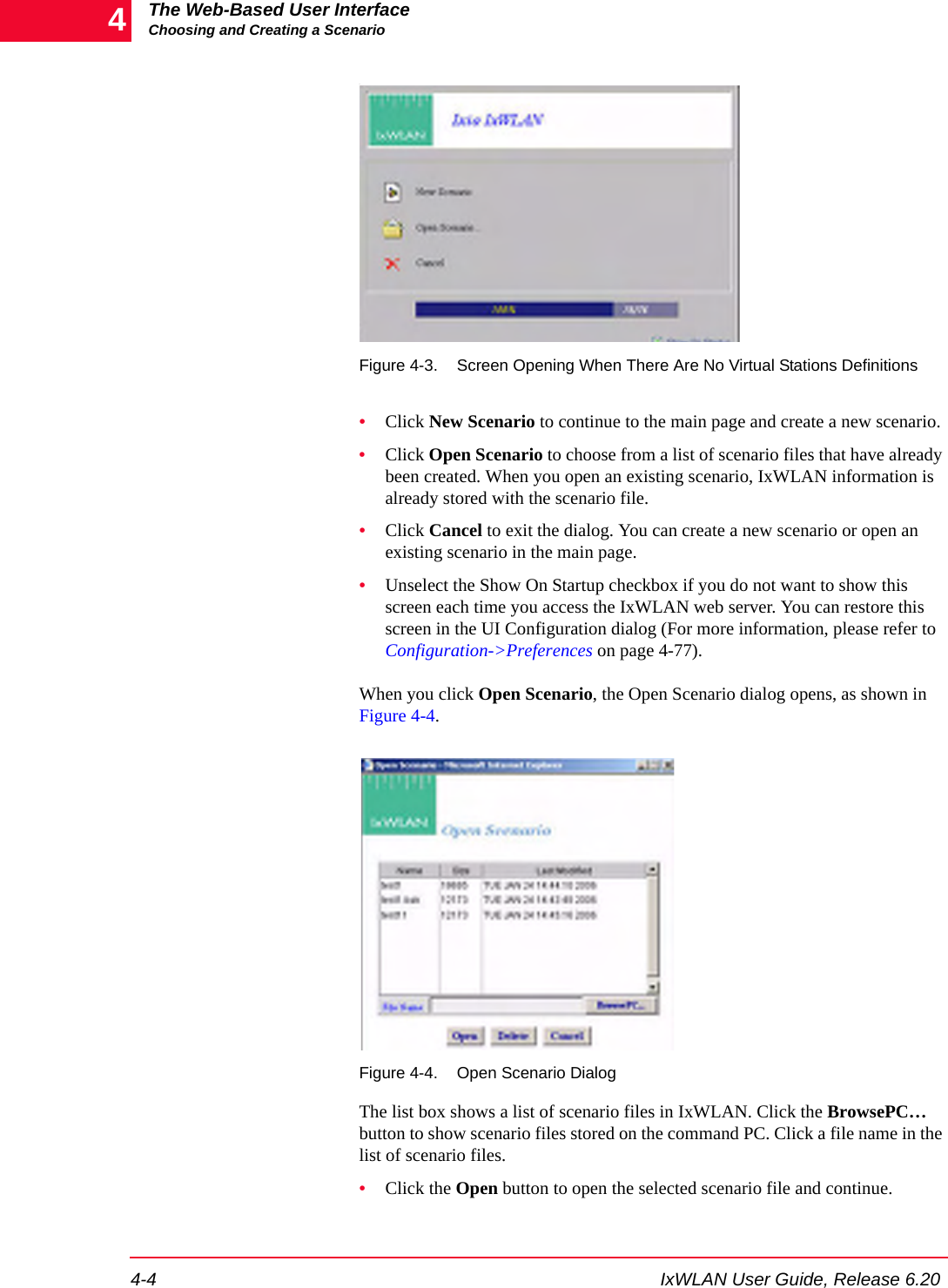
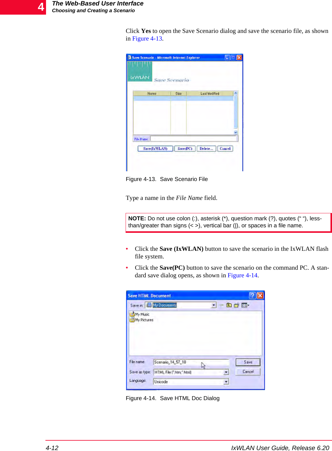
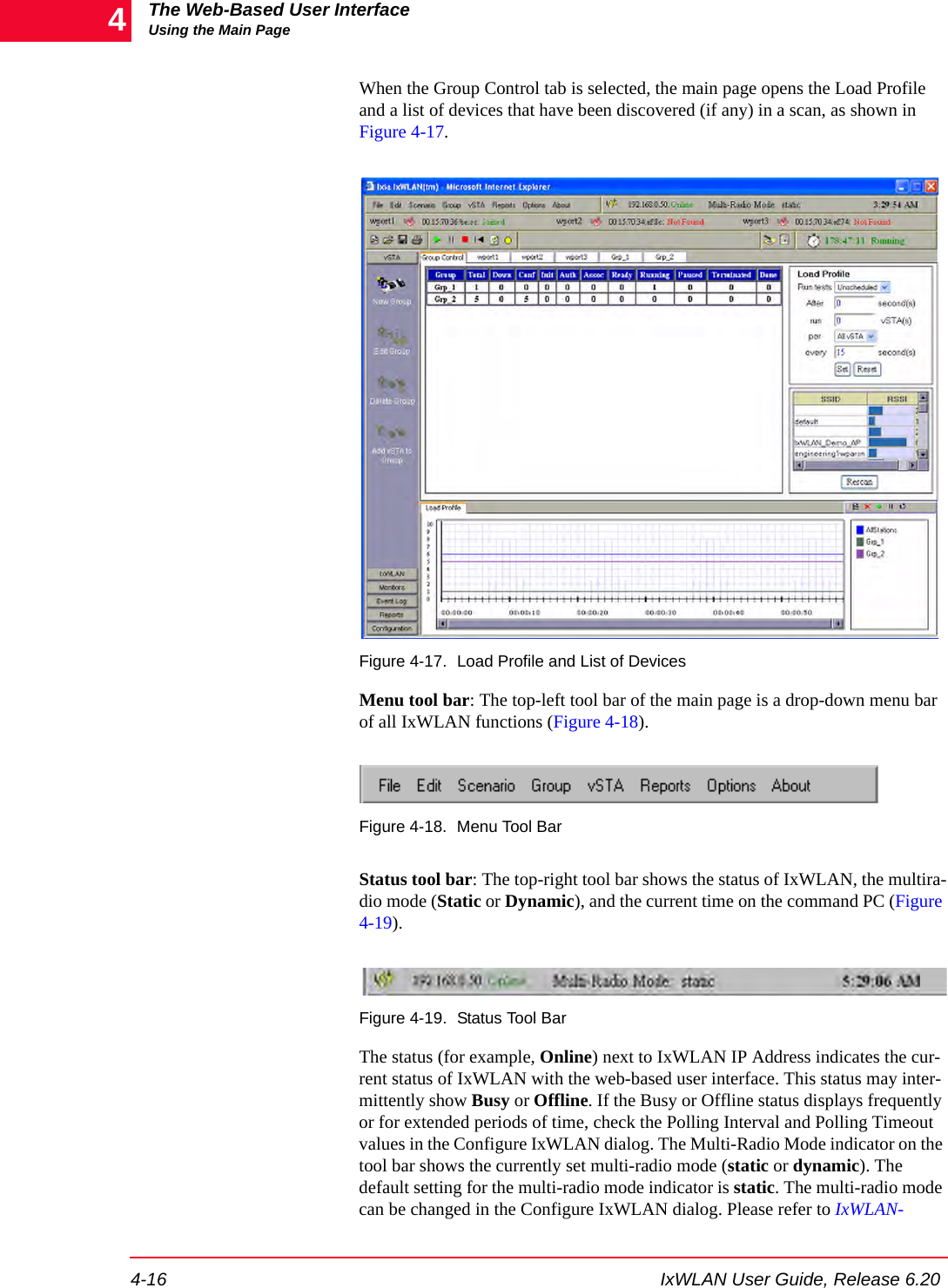
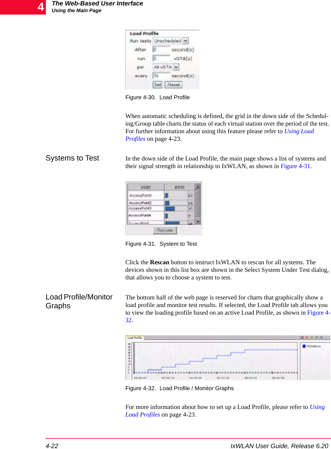
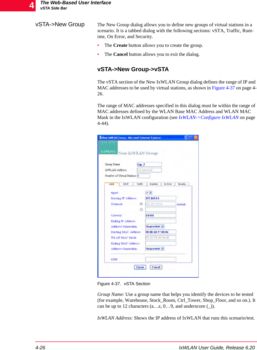
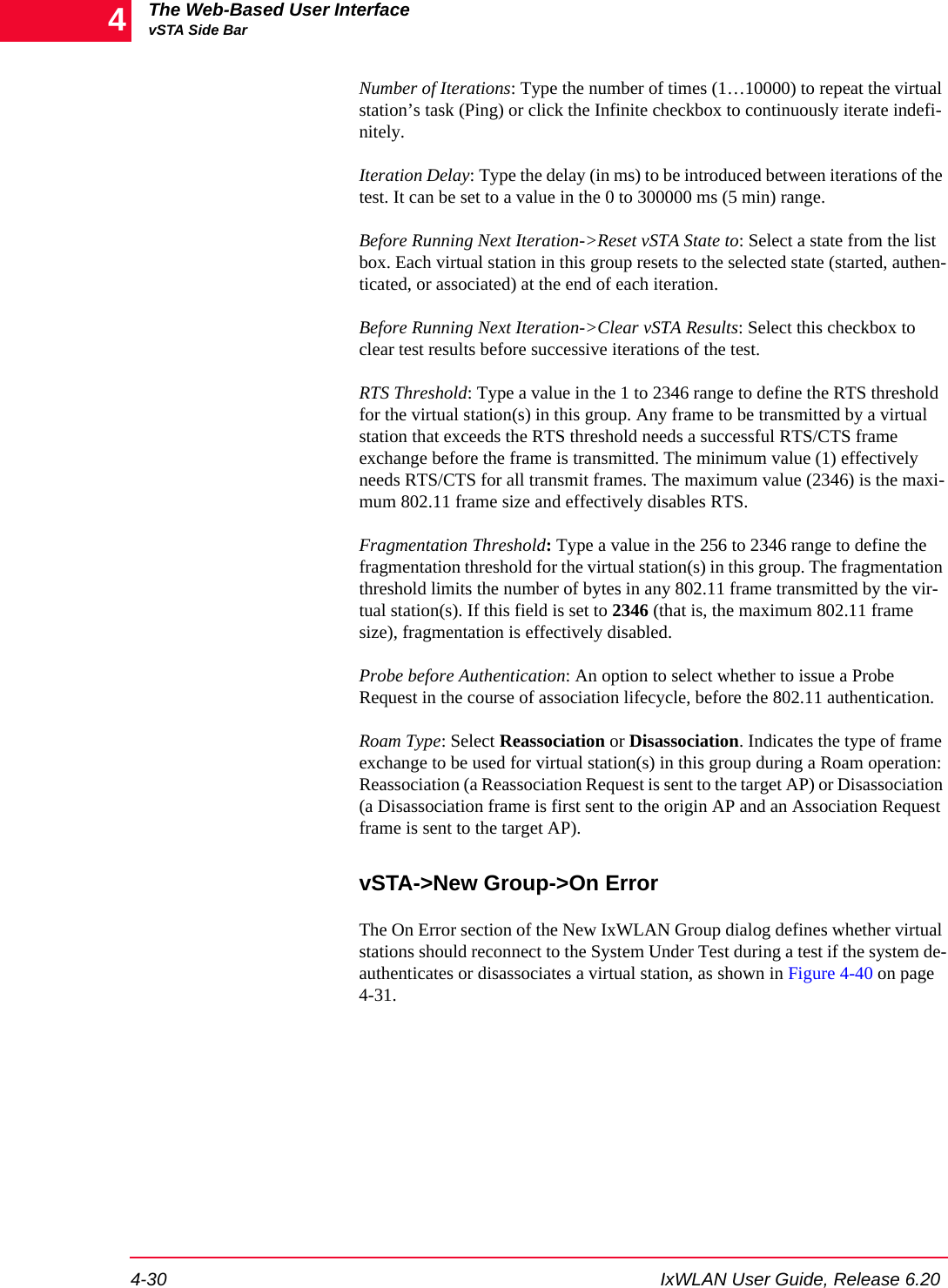
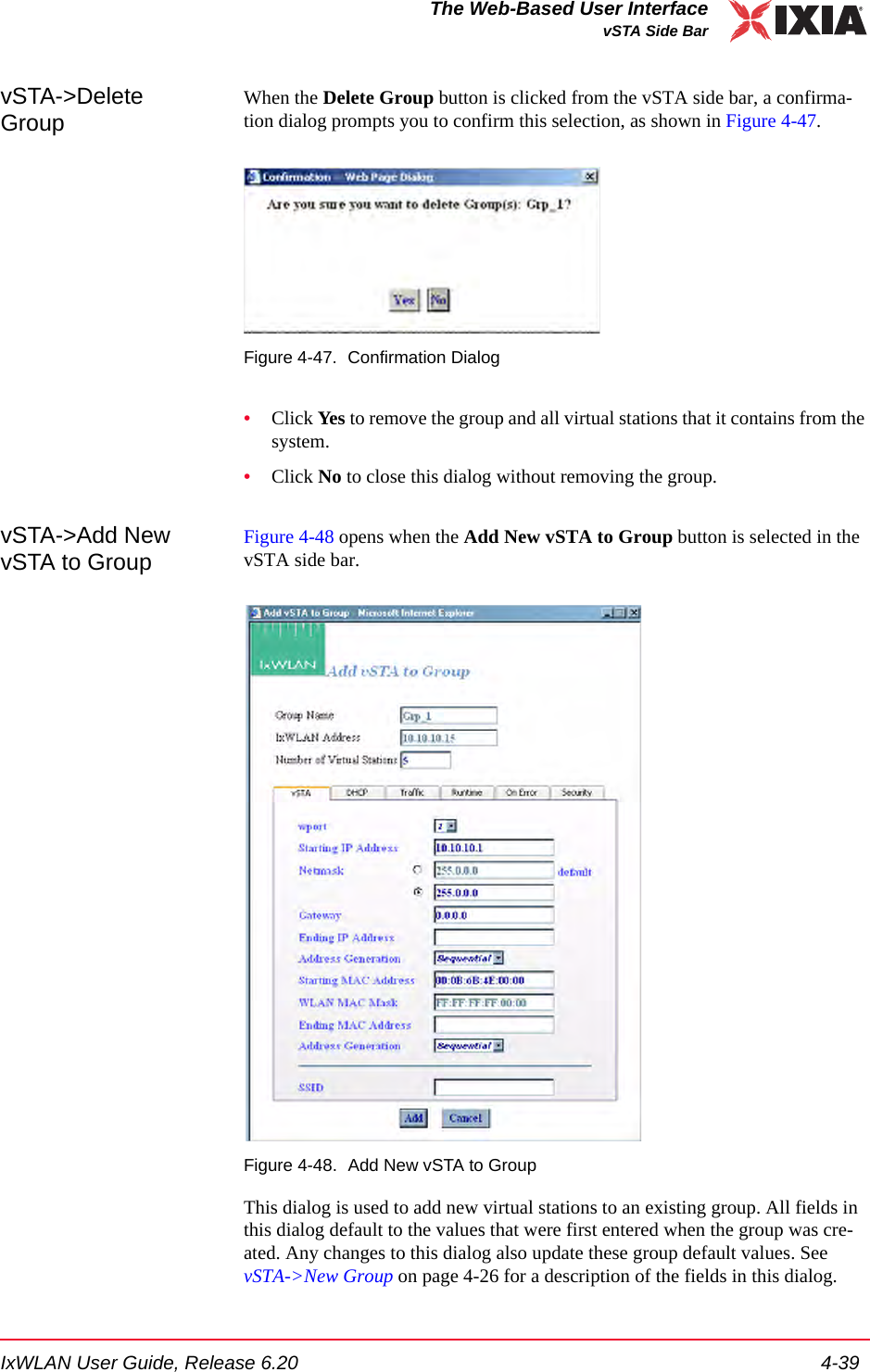
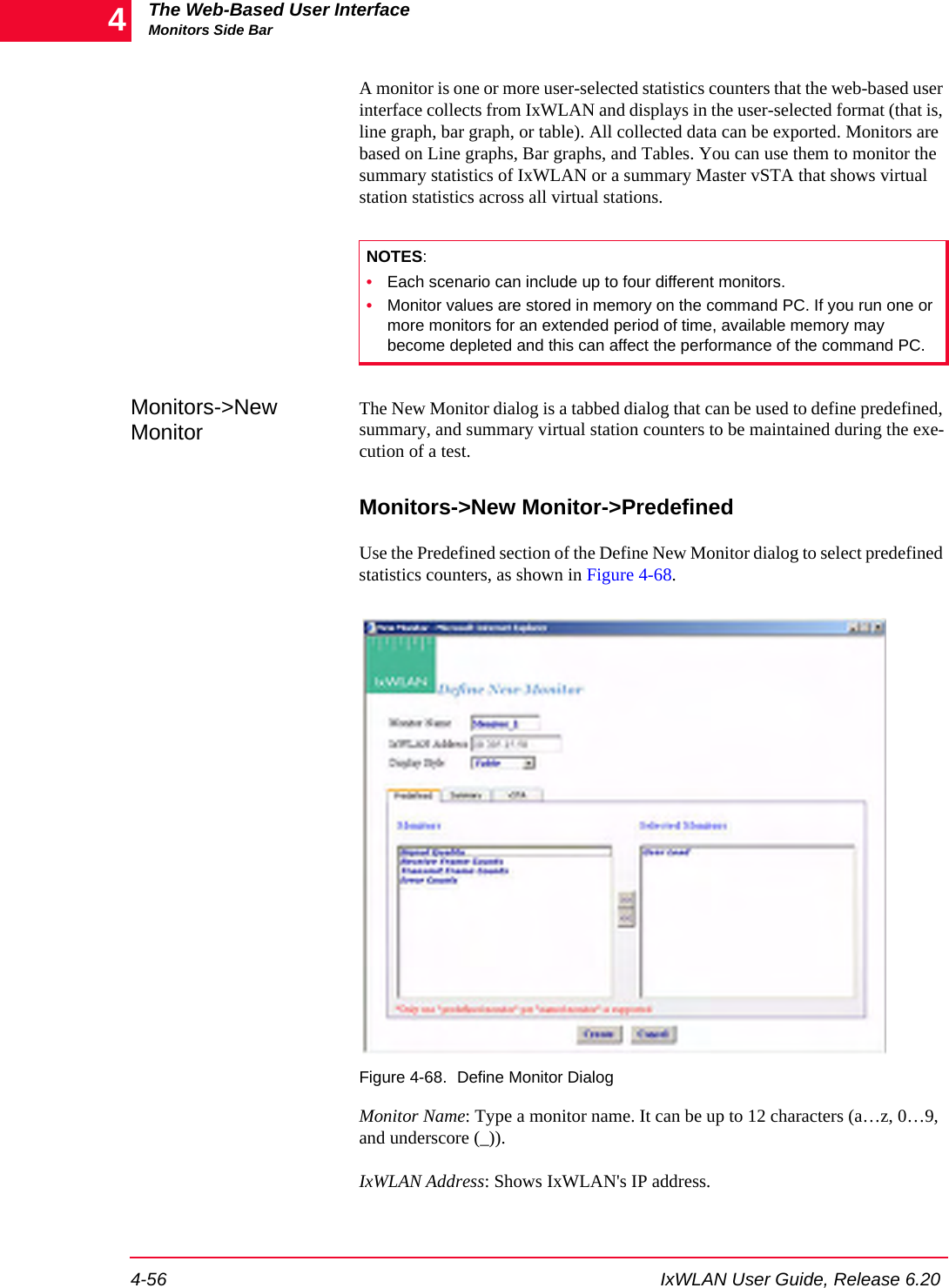
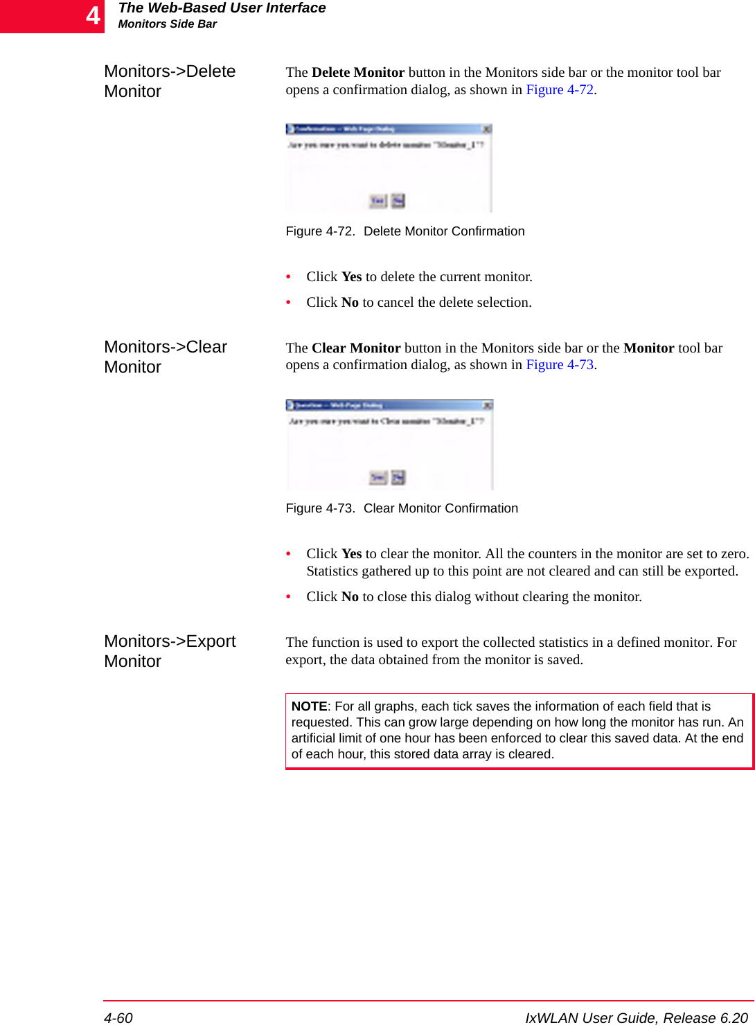
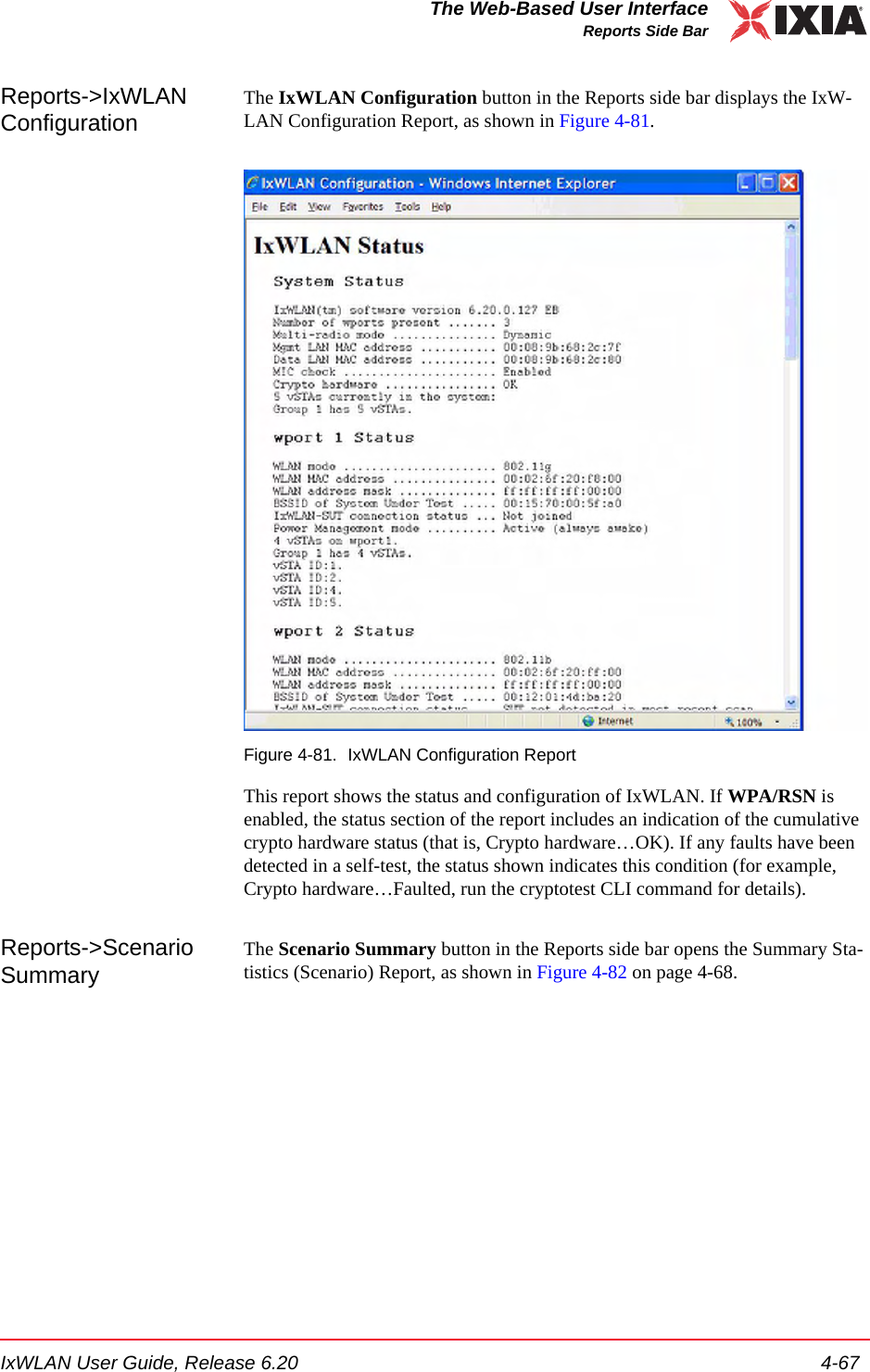
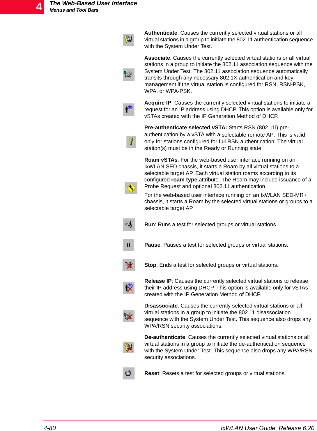
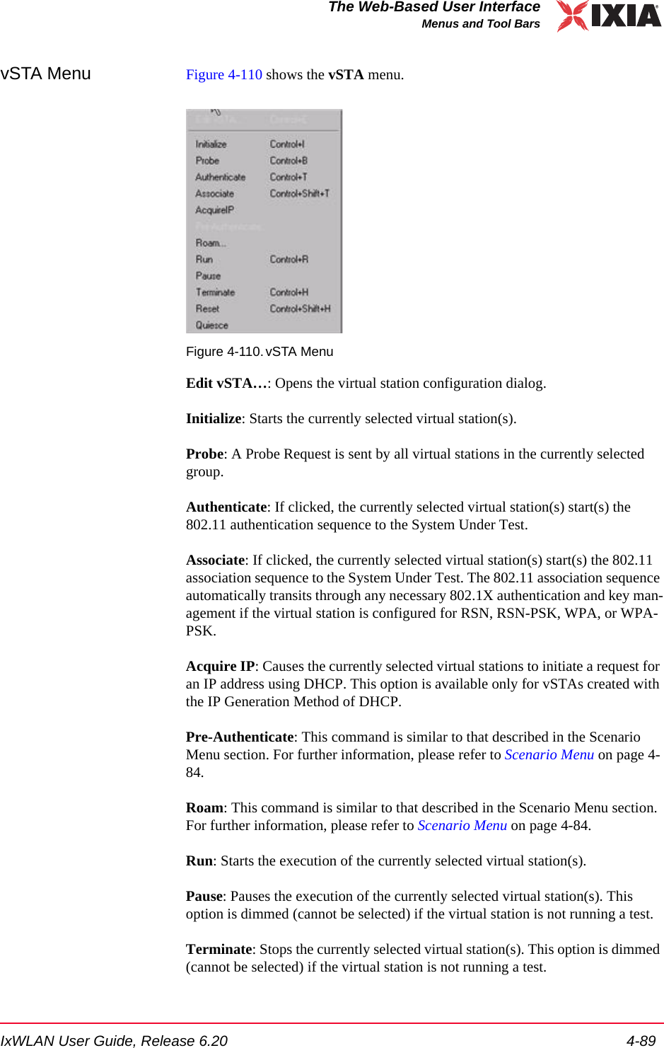
![The Web-Based User InterfaceMonitors Side Bar4-58 IxWLAN User Guide, Release 6.204Monitors->New Monitor->vSTAUse the vSTA section of the Define New Monitor dialog to select the master (summary) virtual station statistics counters, as shown in Figure 4-70.Figure 4-70. vSTA SectionvSTA (s): Select a virtual station from the list box. The Master Station is a sum-mary that shows virtual station statistics across all virtual stations.vSTA Counters->Selected Counters: Select one or more of the counters to be maintained in the test results file. Use the [>>] button to transfer the counters to the Selected Counters column. See Chapter 7, Statistics Counters for a descrip-tion of each of these statistics counters.•Click the Create button to create and display the monitor.•Click the Cancel button to close this dialog.](https://usermanual.wiki/Ixia/GC617644.User-Manual-1/User-Guide-827937-Page-94.png)


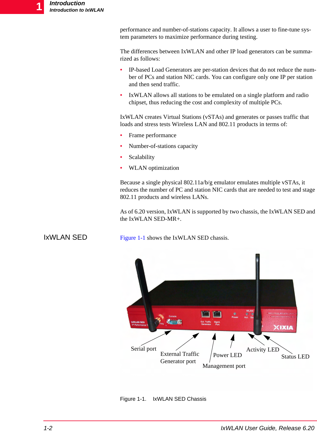
![IxWLAN User Guide, Release 6.20 5-3The Command Line Interface (CLI)CLI Usage Notes•set wlanmac on page 5-85.•reset wlanmac on page 5-77.CLI Usage Notes 1. CLI commands are not case sensitive (for example, set Date is the same as set date). 2. You do not need to type the entire command string to execute a command. Only the number of unique characters needed to identify the command are needed (for example, se da executes the set date command because there are no other CLI commands that begin with se and no other set objects that begin with da).3. Some parameters can be assigned very large values in the 0 to 2,147,483,647 range. Do not type commas (,) for values larger than 999 (for example, use 1000 rather than 1,000).4. It is very important to keep a printed record of configuration parameters. See Configuration Records on page 8-14.User LoginThe IxWLAN logon prompt displays after you successfully establish a connec-tion to IxWLAN. See Chapter 3, First Setup. After you have successfully estab-lished this connection, the CLI prompts you to type a logon name and password. IxWLAN login: AdminPassword: ******The default logon user name is Admin. The default password is IxWLAN. Both entries are case-sensitive (that is, the default user name is Admin, not admin). After you type a valid user name and password, the CLI displays a version ban-ner, the current system time and status, and a CLI prompt (IxWLAN ->).Ixia IxWLAN(tm) Rev 6.20.0.129 EBSystem date & time: FRI APR 20 10:03:31 2007Use the "set date" or "set time" command to adjustIxWLAN(tm) software version 6.20.0.129 EBNumber of wports present ....... 3Multi-radio mode ............... StaticMgmt LAN MAC address ........... 00:08:9b:68:2c:81Data LAN MAC address ........... 00:08:9b:68:2c:82MIC check ...................... EnabledCrypto hardware ................ OK0 vSTAs currently in the system.[wport1]IxWLAN -> The CLI is now ready to accept your commands.](https://usermanual.wiki/Ixia/GC617644.User-Manual-1/User-Guide-827937-Page-131.png)
![The Command Line Interface (CLI)User Logoff5-4 IxWLAN User Guide, Release 6.205User LogoffUse the quit command to log off from the CLI. IxWLAN -> quit After logoff, you must re-establish the telnet connection to log on to the CLI. CLI CommandsThe help command shows a list of all CLI commands. Example:[wport1]IxWLAN -> helpList of IxWLAN CLI commands:acquireip -- Acquire an IP address for a vSTA assoc -- Associate a vSTA with the SUT auth -- Authenticate a vSTA with the SUT autoconf -- Autoconfig-init-auth-assoc N vSTAs autorun -- Run N configured/associated vSTAs clear bssid -- Clear BSSID for System Under Test clear evlog -- Clear event log file or buffer clear group -- Clear vSTA group data clear sntpserver -- Clear SNTP/NTP server IP address clear systemname -- Clear the IxWLAN system name clear vsta -- Clear vSTA data conf -- Configure a vSTA cryptotest -- Crypto hardware self-test deauth -- Deauthenticate a vSTA del group -- Delete a vSTA group del key -- Delete Encryption key del statfile -- Delete a vSTA statistics file del summfile -- Delete a vSTA statistics summary file del vsta -- Delete a vSTA disassoc -- Disassociate a vSTA exec -- Execute a command file ftp -- Software update via FTP get association -- Display Association Table get basic11b -- Display Basic 11b Rates get bootscan -- Display Boot Scan Mode get bkjoin -- Display Background Join get bssid -- Display BSSID of System Under Test get bsslist -- Display list of discovered BSSIDs get channel -- Display Radio Channel get config -- Display current IxWLAN configuration get countrycode -- Display Country Code get cryptocap -- Display crypto hardware capabilities get evlog -- Display event log data get features -- Display authorized featuresNOTE: If the CLI shows the “This IxWLAN has not been Node Locked” message after you type the IxWLAN logon name and password, see Missing Key File on page 8-7.](https://usermanual.wiki/Ixia/GC617644.User-Manual-1/User-Guide-827937-Page-132.png)
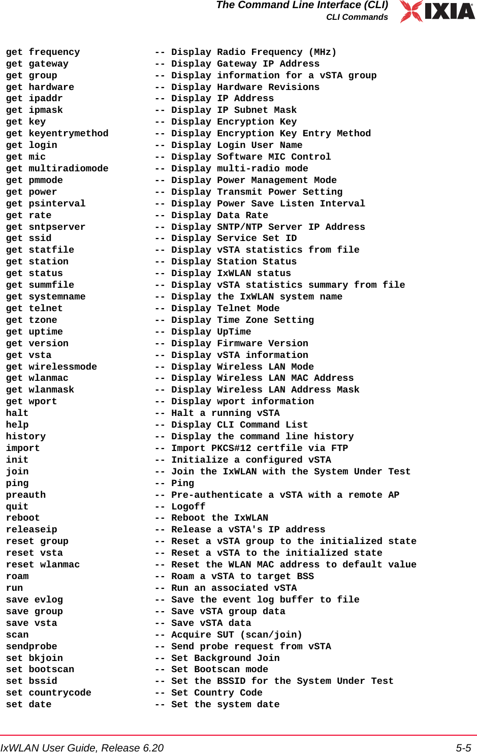
![The Command Line Interface (CLI)CLI Commands5-6 IxWLAN User Guide, Release 6.205 set evlog -- Set event log controls set factorydefault -- Restore to Default Factory Settings set features -- Upgrade current feature set set gateway -- Set Gateway IP Address set group -- Set vSTA group configuration parameters set ipaddr -- Set IP Address set ipmask -- Set IP Subnet Mask set key -- Set Encryption Key set keyentrymethod -- Select Encryption Key Entry Method set login -- Modify Login User Name set mic -- Set Software MIC Control set multiradiomode -- Set multi-radio mode set password -- Modify Password set pmmode -- Set Power Management Mode set power -- Set Transmit Power set psinterval -- Set Power Save Listen Interval set rate -- Set Data Rate set sntpserver -- Set SNTP/NTP Server IP Address set ssid -- Set Service Set ID set systemname -- Set the IxWLAN system name set telnet -- Set Telnet Mode set time -- Set the system time set tzone -- Set Time Zone Setting set vsta -- Set vSTA configuration parameters set wirelessmode -- Set Wireless LAN Mode set wlanmac -- Set WLAN MAC Address set wlanmask -- Set WLAN Address Mask set wport -- Set wport for configuration timeofday -- Display Current Time of Day version -- Software version[wport1]IxWLAN ->This list does not include the commands that are available in the administrative mode. See Administrative Mode Commands on page 5-90 for a list including more commands that are available in the administrative mode. Also, the list of commands is slightly different depending on the wireless mode. If the wireless mode is 802.11a, for example, the list does not include commands that are spe-cific to 802.11g. NOTE: The trace command is available both in the user and admin mode. In the user mode, it is not listed among the other commands in the help output. For details about this command, see Administrative Mode Commands on page 5-90 or trace on page 5-95.](https://usermanual.wiki/Ixia/GC617644.User-Manual-1/User-Guide-827937-Page-134.png)
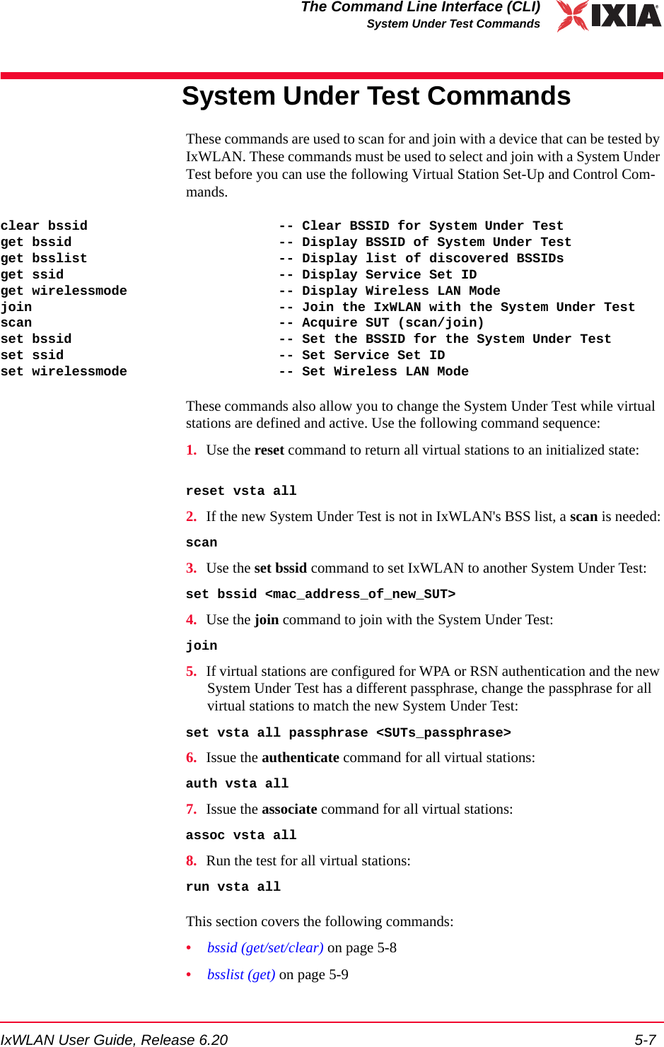
![The Command Line Interface (CLI)System Under Test Commands5-8 IxWLAN User Guide, Release 6.205•join on page 5-10•scan on page 5-11•ssid (get/set) on page 5-13bssid (get/set/clear) get bssidShows the current BSSID/MAC address of the system being tested. get bssidExample:[wport1]IxWLAN -> get bssidBSSID of System Under Test: 00:04:e2:34:e0:a8[wport1]IxWLAN ->set bssidSpecifies the BSSID/MAC address of the system to be tested. This is the System Under Test that IxWLAN scans for and joins with. The default value is all zeros. set bssid <mac_address><mac_address>: MAC address of the System Under Test.Example:[wport1]IxWLAN -> set bssid 00:04:e2:34:e0:a8BSSID of System Under Test: 00:04:e2:34:e0:a8IxWLAN ->IxWLAN -> get bssidBSSID of System Under Test: 00:04:e2:34:e0:a8[wport1]IxWLAN ->clear bssidClears the current BSSID. clear bssidExample:[wport1]IxWLAN -> clear bssidBSSID 00:04:e2:34:e0:a8 cleared use the set bssid CLI command to set the BSSID of the System Under Test[wport1]IxWLAN ->NOTE: IxWLAN must be configured with a non-zero BSSID to perform a Join operation and to create and run virtual stations.](https://usermanual.wiki/Ixia/GC617644.User-Manual-1/User-Guide-827937-Page-136.png)
![IxWLAN User Guide, Release 6.20 5-9The Command Line Interface (CLI)System Under Test Commandsbsslist (get) Shows the Basic Service Sets discovered in the most recent scan. See scan on page 5-11.get bsslist [detail]Use the [detail] option to view detailed information regarding each BSS’s rate capabilities and needs, country code and channel capabilities, and security infor-mation.Example for get bsslist:[wport1]IxWLAN -> get bsslistUse "get bsslist detail" for additional infoType Chan Sec RSSI BSSID SSID---- ---- --- ---- ----- ----AP 44 38 00:05:4e:41:3c:19 QA_A_APAP 60 WEP 61 00:04:e2:37:e6:a1 CK S-1AP 64 TKIP 53 00:0b:6b:30:05:6c cb/wpaAP 149 TKIP 39 00:12:d9:c4:0a:90 s TKIPAP SUT 157 AES 51 00:0b:6b:30:05:65 CK D-1AP 165 52 00:0b:6b:30:05:86 cb/ap1AP: 6, Ad-Hoc: 0, Total BSSs: 6[wport1]IxWLAN ->Type: The Type column indicates the type of BSS detected: AP=Infrastructure BSS, <Type> SUT=System Under Test, Ad-Hoc=Ad-Hoc BSS.Chan: BSS channel number. The BSS list is sorted in channel number order.Sec: Brief description of the security level of the BSS. If multiple security fea-tures are active, this column shows the highest level of security. Use the [detail] option to show all security options in effect.RSSI: The RSSI column shows the relative received signal strength indicator for the BSS. A higher RSSI value indicates that a stronger signal is received.BSSID: The BSSID column shows the BSS identifier.SSID: The SSID column shows the service set identifier for the BSS discovered via a probe request.Example for get bsslist detail:[wport1]IxWLAN -> get bsslist detailBSS Type Channel RSSI BSSID SSID-------- ------- ---- ----- ----AP BSS 5.220 ( 44) 38 00:05:4e:41:3c:19 QA_A_AP Rates: *6, 9, *12, 18, *24, 36, 48, 54AP BSS 5.300 ( 60) 61 00:04:e2:37:e6:a1 CK S-1 Rates: *6, 9, *12, 18, *24, 36, 48, 54 Security: WEPAP BSS 5.320 ( 64) 53 00:0b:6b:30:05:6c cb/wpa Rates: *6, 9, *12, 18, *24, 36, 48, 54 Security: WPA/EAP/TKIP](https://usermanual.wiki/Ixia/GC617644.User-Manual-1/User-Guide-827937-Page-137.png)
![The Command Line Interface (CLI)System Under Test Commands5-10 IxWLAN User Guide, Release 6.205 Country: US [ 52 (5260) 4 23] [ 36 (5180) 4 17] [149 (5745) 5 30]AP BSS 5.745 (149) 39 00:12:d9:c4:0a:90 s TKIP Rates: *6, *9, *12, *18, *24, *36, *48, *54 Security: WPA/PSK/TKIPAP BSS 5.785 (157) 51 00:0b:6b:30:05:65 CK D-1 * * This is the System Under Test * * Rates: *6, 9, *12, 18, *24, 36, 48, 54 Security: RSN/PSK/AES/TKIP Country: US [ 52 (5260) 4 23] [ 36 (5180) 4 17] [149 (5745) 5 30]AP BSS 5.825 (165) 52 00:0b:6b:30:05:86 cb/ap1 Rates: *6, 9, *12, 18, *24, 36, 48, 54 Country: US [ 52 (5260) 4 23] [ 36 (5180) 4 17] [149 (5745) 5 30]AP: 6, Ad-Hoc: 0, Total BSSs: 6The get bsslist detail command shows detailed information regarding the rate capabilities and needs, country code and channel capabilities, and security infor-mation of each BSS. This information is presented as it is read from the BSS’s Beacon or Probe Response, when present. Not all APs broadcast this detail infor-mation. It is shown only when available.The first line of each BSS detail line item shows the basic BSS information: type, channel, RSSI, BSSID, and SSID. The * * This is the System Under Test * * message displays after the basic BSS information line if the System Under Test is specified and detected.Rates: This line indicates the set of transmit rates supported in the BSS. Entries marked by an asterisk (for example, *6, *24) indicate a member of the BSS’s basic rate set.Security: This line indicates all security information that can be determined pas-sively through inspection of information found in the Beacon or Probe Response. WEP indicates basic WEP encryption. WPA or RSN indicate higher security in the form of advanced authentication and encryption algorithms. PSK indicates Pre-Shared Key authentication. EAP indicates the use of a more robust EAP-based authentication algorithm. TKIP and AES indicate the cipher algorithm in use. A WPA or RSN BSS may support more than one authentication or cipher suite.Country: This line indicates information found in the Country information ele-ment, when present. This includes the country code and the channel list. The channel list is formatted in the form: [first channel, number of channels, maxi-mum transmit power]. Example: [ 52 (5260) 4 23]. In this example, first chan-nel=52, number of channels =4, maximum transmit power=23.join Joins with the System Under Test. It must be present in the current Basic Service Set list. See bsslist (get) on page 5-9.joinExample:[wport1]IxWLAN -> join The join should take about 1 sec [wport1]IxWLAN -> IxWLAN: wport1 Join: Checking BSS ... OK](https://usermanual.wiki/Ixia/GC617644.User-Manual-1/User-Guide-827937-Page-138.png)
![IxWLAN User Guide, Release 6.20 5-11The Command Line Interface (CLI)System Under Test Commands IxWLAN: wport1 Join: Checking channel ... OK IxWLAN: wport1 Join: Initiating JOIN ... Infrastructure 5.260 29 00:0b:6b:30:05:9f ixia/dmm/atheros IxWLAN: wport1 Join: channel 52 (5260 MHz), ixia/dmm/atheros OK wport1 NOTIFY Operation JOIN succeeded - FRI MAR 30 14:05:57 2007 [wport1]IxWLAN ->Example:[wport1]IxWLAN -> join The join should take about 1 sec [wport1]IxWLAN -> IxWLAN: wport1 Join: Checking BSS ... OK IxWLAN: wport1 Join: Checking channel ... OK IxWLAN: wport1 Join: Initiating JOIN ... Infrastructure 5.240 58 00:0b:6b:30:05:86 AccessPoint_1 IxWLAN Join: channel 157 (5785 MHz), CK D-1 OK [wport1]IxWLAN -> vSTA 1 PSK: f769e4fdc6b97b780c7f3799c6d58ce7250ca3779930cb4d2545dacbc45092d1 [wport1]IxWLAN -> wport1 NOTIFY Operation JOIN succeeded - MON MAY 09 10:42:30 2005 [wport1]IxWLAN ->scan Scans for Basic Service Set IDs and optionally joins with the System Under Test. The IxWLAN wireless mode affects the type of devices that can be detected in a scan. To change the IxWLAN wireless mode, see Virtual Station Setup and Control Commands on page 5-14. [wport1]IxWLAN -> scanActive (probe request) or passive (listen for beacons) [a/p: p]?Type a and press ENTER to select an active scan. Just press ENTER to select the default passive mode. If the passive mode is selected, the CLI prompts for the following scanning options:Channel (0 = all, m=all modes) [0]?Channel timeout in msec [300]?If typing m for the channel, all valid channels in all valid modes are scanned.The default entry of 0 selects all valid channels in the current wireless mode.NOTE: If any virtual stations are configured for WPA-PSK or RSN-PSK authentication using a passphrase and IxWLAN is already joined at the time a join command selects a different SSID, the Pre-Shared Keys is regenerated for every vSTA that has a passphrase set. NOTE: If a test is in process (see get wirelessmode on page 5-73), a scan operation is disruptive to the normal testing operations of IxWLAN.](https://usermanual.wiki/Ixia/GC617644.User-Manual-1/User-Guide-827937-Page-139.png)
![The Command Line Interface (CLI)System Under Test Commands5-12 IxWLAN User Guide, Release 6.205If the active mode is selected, the CLI prompts for the following scanning options:Broadcast or directed probe request [b/d: d]?Channel (0 = all, m=all modes) [0]?Channel timeout in msec [300]?In response to the Channel prompt, you may type zero for all channels or any valid 802.11a or 802.11b/g channel number or frequency. The range of channels/frequencies depends on the wireless mode and the features that are enabled on IxWLAN. See the specifications in Appendix A, Specifications for a list of valid channel numbers and frequencies for 802.11a, 802.11b, and 802.11g.The CLI prompts to join with a system (if any) found in the scan. If IxWLAN is already joined with a System Under Test, the default response is y:Attempt a join with SUT 00:04:e2:38:56:78 [y/n: y]? If IxWLAN is not joined with a System Under Test, the default response is n:Attempt a join with SUT 00:04:e2:38:56:78 [y/n: n]? Type y or n and press ENTER or just press ENTER to select the default.Example:[wport1]IxWLAN -> scanActive (probe request) or passive (listen for beacons) [a/p:p]?Channel (0 = all) [0]?Channel timeout in msec [300]?Attempt a join with SUT 00:04:e2:38:a8:d2 [y/n: n]?The scan should take about 4 sec[wport1]IxWLAN -> OK[wport1]IxWLAN ->[wport1]IxWLAN ->Passive scanning 5 GHz 54Mbps (802.11a) channels for 4 seconds...Select BSS: Looking for .. 00:04:E2:38:A8:D2Select BSS: Found ........ 00:04:E2:38:A8:D2 => BSS'es from the selected wireless mode <=BSS Type Channel RSSI BSSID SSID-------- ------- ---- ----- ----SUT BSS 5.220 ( 44) 31 00:04:e2:38:a7:87 AccessPoint_1SUT BSS 5.260 ( 52) 55 00:04:e2:38:a8:d2 AccessPoint_2SUT BSS 5.280 ( 56) 46 00:04:e2:38:56:68 AccessPoint_3SUT BSS 5.300 ( 60) 44 00:04:e2:37:e6:a1 AccessPoint_4SUT: 4, Ad-Hoc: 0. Total BSS: 4 wport1 NOTIFY Operation SCAN succeeded - FRI MAR 30 14:14:52 2007wport1 NOTIFY Operation SCAN&JOIN succeeded - FRI MAR 30 14:14:52 2007[wport1]IxWLAN -> scanActive (probe request) or passive (listen for beacons) [a/p: p]? aBroadcast or directed probe request [b/d: d]?](https://usermanual.wiki/Ixia/GC617644.User-Manual-1/User-Guide-827937-Page-140.png)
![IxWLAN User Guide, Release 6.20 5-13The Command Line Interface (CLI)System Under Test CommandsChannel (0 = all) [0]? 2412Channel timeout in msec [300]?Attempt a join with SUT 00:04:e2:38:a8:d2 [y/n: n]?The scan should take about 1 sec[wport1]IxWLAN -> OK[wport1]IxWLAN ->[wport1]IxWLAN -> InitSingleScan -- 2412, a00 cck 2.4Active scanning 2.4GHz 11Mbps (802.11b) channels for 1 seconds...wlanMlmeProbeRequest -- channel 2412Select BSS: Looking for .. 00:04:E2:38:A8:D2Select BSS: Found ........ 00:04:E2:38:A8:D2InitSingleScan -- 2412, a00 cck 2.4Active scanning 2.4GHz 11Mbps (802.11b) channels for 1 seconds...wlanMlmeProbeRequest -- channel 2412wport1 NOTIFY Operation SCAN succeeded - FRI MAR 30 14:14:52 2007wport1 NOTIFY Operation SCAN&JOIN succeeded - FRI MAR 30 14:14:52 2007[wport1]IxWLAN ->ssid (get/set) get ssidDisplays the IxWLAN global Service Set Identifier attribute.[wport1]IxWLAN -> get ssidSSID: IxWLAN Test Wireless Network[wport1]IxWLAN ->set ssidSets the given value to the IxWLAN global Service Set Identifier attribute.To reset the global SSID to the factory default string, enter the following com-mand: set ssid default.[wport1]IxWLAN -> set ssid default * * * * DO NOT REMOVE POWER FROM THE IxWLAN UNIT! * * Wait for the IxWLAN to update the configuration file in Flas * * or use the "reboot" command for immediate update & reboot. * * Automatic update will be done within one minute. * *[wport1]IxWLAN -> ...Configuration file update completed.get ssidSSID: IxWLAN Test Wireless Network](https://usermanual.wiki/Ixia/GC617644.User-Manual-1/User-Guide-827937-Page-141.png)
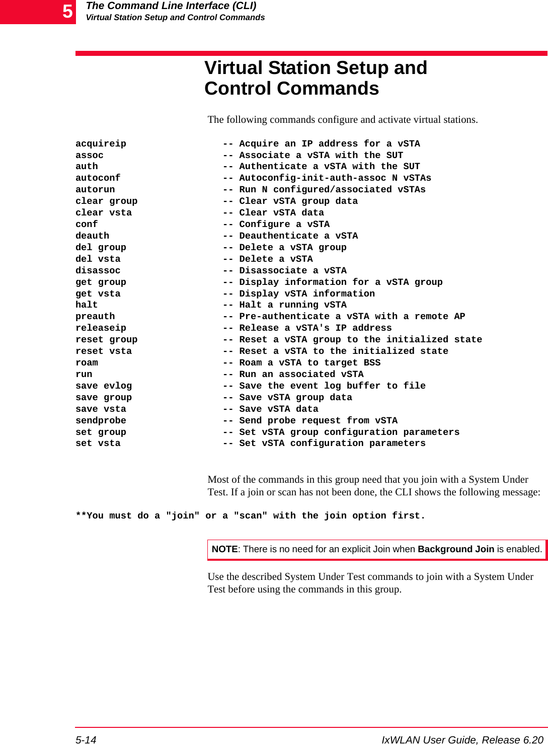
![The Command Line Interface (CLI)Virtual Station Setup and Control Commands5-16 IxWLAN User Guide, Release 6.205acquireip Starts the DHCP negotiation process for the specified virtual station(s). The vir-tual station must be in the 802.11 Associated state or 802.1X authenticated if security is turned on and the vSTA’s DHCP mode (dhcpmode) must be set to on. See autoconf on page 5-18, conf on page 5-24 and set vsta on page 5-46 for infor-mation about setting the DHCP mode. The following command starts the DHCP negotiation process for one or all vir-tual stations. acquireip vsta <vStaId><vStaId>: Virtual Station ID (1…128) or all. If <vStaId> is set to all (that is, acquireip vsta all), the DHCP negotiation process is initiated for all virtual sta-tions.The following command starts the DHCP negotiation process for all virtual sta-tions in a specified group.acquireip group <grpId><grpId>: Group ID (1…128)Example:[wport1]IxWLAN -> acquireip vsta 1[wport1]IxWLAN -> OKvSTA ID:1 NOTIFY Operation ACQIP (10.1.35.10) succeeded - THU JAN 08 10:04:31 2004assoc Starts the 802.11 association sequence for one or more virtual stations. The 802.11 association sequence automatically transits through any necessary 802.1X authentication and key management if the virtual station is configured for RSN, RSN-PSK, WPA, or WPA-PSK. The virtual station(s) must be configured, ini-tialized, and authenticated before this command can be used. The following command starts the association sequence for one or all virtual sta-tions. assoc vsta <vStaId><vStaId>: Virtual Station ID (1…128) or all. If <vStaId> is set to all (that is, assoc vsta all), the association sequence is initiated for all virtual stations.The following command starts the association sequence for all virtual stations in a specified group.assoc group <grpId><grpId>: Group ID (1…128)](https://usermanual.wiki/Ixia/GC617644.User-Manual-1/User-Guide-827937-Page-144.png)
![IxWLAN User Guide, Release 6.20 5-17The Command Line Interface (CLI)Virtual Station Setup and Control CommandsExample:[wport1]IxWLAN -> assoc vsta 1[wport1]IxWLAN -> OK[wport1]IxWLAN ->vSTA ID:1 NOTIFY Operation ASSOC succeeded - TUE JUL 15 03:08:38 2003[wport1]IxWLAN ->When a virtual station is configured for WPA-PSK authentication, this command shows additional AKMP information. Example for WPA-PSK:[wport1]IxWLAN -> assoc vsta 1[wport1]IxWLAN -> OK[wport1]IxWLAN ->vSTA ID:1 NOTIFY Operation ASSOC succeeded - WED MAY 26 10:38:57 2004[wport1]IxWLAN ->vSTA ID:1 NOTIFY Remote initiated AKMP - WED MAY 26 10:38:57 2004[wport1]IxWLAN ->vSTA ID:1 NOTIFY AKMP succeeded - WED MAY 26 10:38:57 2004[wport1]IxWLAN ->When a virtual station is configured for WPA or RSN authentication, this com-mand shows an additional NOTIFY message for the 802.1X authentication oper-ation.Example for WPA:[wport1]IxWLAN -> assoc vsta 1[wport1]IxWLAN -> OK[wport1]IxWLAN ->vSTA ID:1 NOTIFY Operation ASSOC succeeded - WED MAY 26 10:38:57 2004[wport1]IxWLAN ->vSTA ID:1 NOTIFY 1XAUTH succeeded - WED MAY 26 10:38:57 2004[wport1]IxWLAN ->vSTA ID:1 NOTIFY Remote initiated AKMP - WED MAY 26 10:38:57 2004[wport1]IxWLAN ->vSTA ID:1 NOTIFY AKMP succeeded - WED MAY 26 10:38:57 2004[wport1]IxWLAN ->auth Starts the 802.11 authentication sequence for one or more virtual stations. The virtual station(s) must be configured and initialized before this command can be used. The following command starts the authentication sequence for one or all virtual stations. auth vsta <vStaId><vStaId>: Virtual Station ID (1…128) or all. If <vStaId> is set to all (that is, auth vsta all), the authentication sequence is initiated for all virtual stations.](https://usermanual.wiki/Ixia/GC617644.User-Manual-1/User-Guide-827937-Page-145.png)
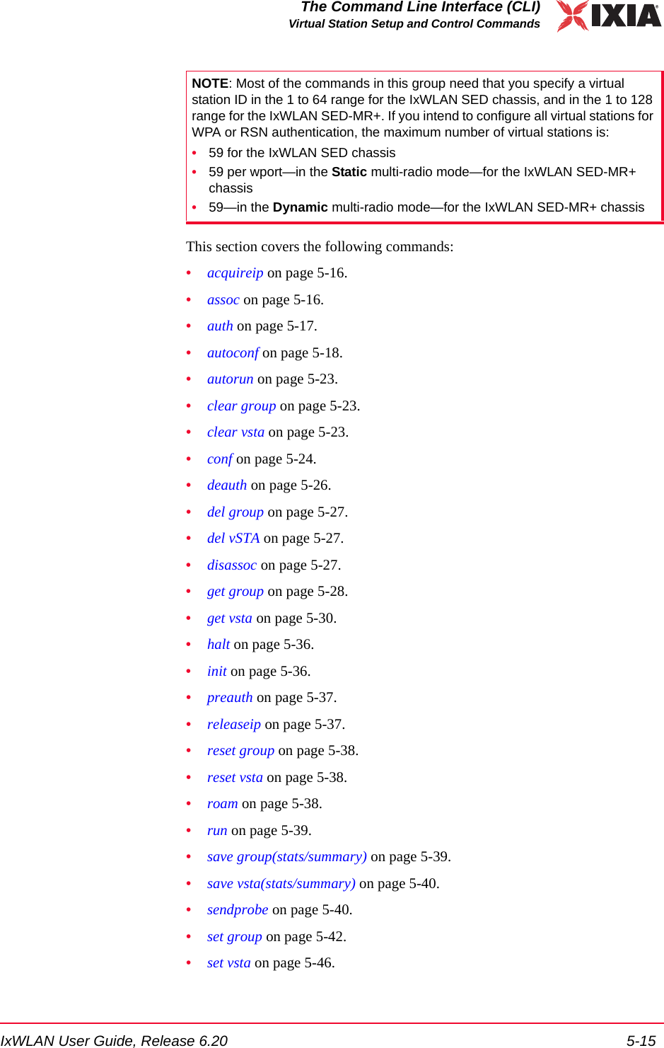
![The Command Line Interface (CLI)Virtual Station Setup and Control Commands5-18 IxWLAN User Guide, Release 6.205The following command starts the authentication sequence for all virtual stations in a specified group.auth group <grpId><grpId>: Group ID (1…128)Example:[wport1]IxWLAN -> auth vsta 1[wport1]IxWLAN -> OK[wport1]IxWLAN ->vSTA ID:1 NOTIFY Operation AUTH succeeded - TUE JUL 15 03:08:15 2003 [wport1]IxWLAN ->autoconf This command allows you to configure, initialize, authenticate, and associate a number of virtual stations using a single command. It can be issued multiple times. The first time the command is issued, the base MAC and IP virtual station addresses must be specified. For subsequent commands, the IP and MAC address parameters are not needed. The specified number of virtual stations is configured using either default values or the values specified in the command line. Except for the number of virtual stations to be configured, values are specified using a “name/value” pair syntax and may be given in any order. autoconf <num> mac <mac_addr> [ip <ip_addr>] [group <grpId>] [wport <integer>] [gateway <ip_addr>] [ipmask <ip_mask>] [csmode persistent|non-persistent] [retry <integer>] [timeout <integer>] [fastradius enabled|disabled] [pmkcache enabled|disabled] [roamtype disassociation|reassociation] [encryption on|off] [keyindex <integer>] [fragmentthreshold <integer>] [rtsthreshold <integer>] [mode external] [layer 2 | 3] | [mode internal] target <ip_addr> [count <integer>] [size <integer>] [dhcpmode off | on | auto] [dhcplease <integer>] [dhcpretry <integer>] [dhcpinterval <integer>] [dhcpoffers <integer>] [dhcpserver <ip_addr>][SSID <string> | <quoted-string> | wildcard] [probe4auth] [authentication open-system|shared-key|rsn-psk|rsn|wpa-psk|wpa] [cipher wep|tkip|aes-ccm] [psk <key>] [passphrase <quoted-phrase>] [eapalgorithm tls|peap|ttls] [certfile <filename>] [userid <string>] [inneralgorithm <inner-auth-id>] [password <inner-auth-passwd>] [outeridentity <outer-auth-ID>] [kmtimeout <integer>]<num>: Specifies the number of virtual stations to be configured. For IxWLAN SED, the maximum number of vSTAs is 64, while IxWLAN SED-MR+ supports a maximum number of 128 vSTAs. If this is not the first autoconf command, new virtual stations are configured starting with the last virtual station and increment-ing for <num>. Default: None.mac <mac_address>: Specifies the base/starting value to be used for virtual sta-tion MAC addresses. This parameter is needed for the first autoconf command and should not be specified for subsequent commands. Default: Last MAC address + 1. The starting MAC address must be within the range of MAC](https://usermanual.wiki/Ixia/GC617644.User-Manual-1/User-Guide-827937-Page-146.png)
![IxWLAN User Guide, Release 6.20 5-19The Command Line Interface (CLI)Virtual Station Setup and Control Commandsaddresses defined by the WLAN Base MAC Address and WLAN MAC Mask configured for the specified wport (see set wlanmac on page 5-85 and set wlanmask on page 5-85).ip <ip_address>: Specifies the base/starting value to be used for virtual station IP addresses. This parameter is needed for the first autoconf command and should not be specified for subsequent commands. Default: Last IP address + 1.[group <grpId>]: Specifies an optional group ID number (1…128). [wport <integer>]: Creates the virtual station(s) on the specified wport. If this parameter is not specified, the virtual station(s) is/are created on the current wport.[gateway <ip_addr>]: Specifies the IP address of the gateway to be used by the vSTA.[ipmask <ip_mask>]: Specifies the subnet mask to be used by a vSTA.[csmode persistent | non-persistent]: Specifies the connection mode (persistent or non-persistent). [retry <integer>]: Specifies the Authentication/Association retry limit (1…2,147,483,647 or zero (0=no retries)).[timeout <integer>]: Specifies the Authentication/Association timeout, in ms (1…2,147,483,647 or zero (0=immediate timeout)).[fastradius enabled | disabled]: Enables the fast RADIUS reconnection when (re)associating or pre-authenticating. The default is Disabled.[pmkcache enabled | disabled]: Enables the use of cached PMKSA information when (re)associating. The default value of this attribute is Enabled. Cached PMKSA information may be used by virtual stations configured for full RSN (802.11i) authentication.[roamtype disassociation | reassociation]: Selects the roam type. The default value for roamtype is reassociation.[authentication open-system|shared-key|wpa-psk|wpa|rsn|rsn-psk]: Defines the authentication mode: open-system, shared-key, wpa-psk, wpa, rsn, or rsn-psk. [encryption on|off]: Specifies the encryption mode (on or off). [keyindex <integer>]: If encryption is on and authentication is shared-key, this parameter specifies a shared key index number (1…4). These shared keys are defined by the set key command.[cipher wep | tkip | aes-ccm]: Enables WEP, TKIP, or AES-CCM (that is, CCMP) cipher mode. If authentication is open-system or shared-key, wep is the only valid selection.](https://usermanual.wiki/Ixia/GC617644.User-Manual-1/User-Guide-827937-Page-147.png)
![The Command Line Interface (CLI)Virtual Station Setup and Control Commands5-20 IxWLAN User Guide, Release 6.205[mode internal | external]: If mode is internal, virtual station(s) generate data using Ping (ICMP Echo Request) packets. Each virtual station runs a ping trans-mitter process. The packets contain virtual station IP and MAC source address. If internal is specified, the target parameter must also be specified. If mode is external, data for virtual station(s) is generated by an external host connected to the same LAN as IxWLAN. For vSTAs configured at layer 3, IP and ARP pack-ets generated from this host that contain the virtual station's IP address as a source is translated at the MAC layer to appear as if sourced from the virtual sta-tion's MAC address. Default: internal. [target <ip_address>]: If mode is internal, this parameter specifies the target host's IP address. If mode is internal, this parameter is needed. Default: None.[count <integer>]: If mode is internal, this parameter specifies the number of ping packets to send: 0…2,147,483,647. Default: 1000. [size <integer>]: If mode is internal, this parameter specifies the size of the ping data buffer (64…1024). Default: 1024.[dhcpmode <off | on | auto>]: The DHCP mode allows virtual stations to have IP addresses dynamically acquired from a DHCP server on the network rather than a fixed, configured IP address. If dhcpmode is off, DHCP mode is not active and virtual stations must have a static IP address. If dhcpmode is on, the acquireip command must be used to initiate lease negotiation. If dhcpmode is auto, IxW-LAN automatically starts lease negotiation if the association succeeds. The default value is off. [dhcplease <integer>]: Specifies the lease time that a vSTA is to request.[dhcpretry <integer>]: Specifies the number of times that a vSTA retries a DHCP operation (discover, request) before timing out.[dhcpinterval <integer>]: Specifies the interval between retries.[dhcpoffers <integer>]: Specifies the number of offers to ignore before generat-ing a request.[dhcpserver <ip_addr>]: If set, specifies the DHCP server from which a vSTA is to accept offers (needed when testing with multiple servers).[SSID <string> | <quoted-string> | wildcard]: The SSID is used in (re)association and in computing the pre-shared key from a passphrase for WPA/RSN-PSK. The default value for a vSTA’s SSID is Not Set. If set to Wildcard, the SSID used in the probe and association/re-association requests is the wildcard SSID and the frame contains an SSID Information Element with a length of 0.[probeb4auth]: Directs the autoconfig command to issue the sendprobe com-mand before issuing the auth command.[layer <2 | 3>]: If mode is external, this parameter specifies how the external data stream is captured. If layer is 2, frames are captured based on the source](https://usermanual.wiki/Ixia/GC617644.User-Manual-1/User-Guide-827937-Page-148.png)
![IxWLAN User Guide, Release 6.20 5-21The Command Line Interface (CLI)Virtual Station Setup and Control Commands802.3 MAC address. If layer is 3, frames are captured based on the source IP address. The default value is 3.[fragmentthreshold <nBytes>]: <nBytes> can be a value in the 256…2346 range and defines the fragmentation threshold for the virtual station(s) configured by this command. The fragmentation threshold limits the number of bytes in any 802.11 frame transmitted by the vSTA. If <nBytes> is set to 2346 (that is, the maximum 802.11 frame size), fragmentation is effectively disabled. The default value is 2346.[rtsthreshold <nBytes>]: <nBytes> can be a value in the 1…2346 range and defines the RTS threshold for the virtual station(s) configured by this command. Any frame to be transmitted by a vSTA that exceeds the vSTA’s RTS threshold needs a successful RTS/CTS frame exchange before the frame is transmitted. The minimum value (1) effectively needs RTS/CTS for all transmit frames. The maximum value (2346) is the maximum 802.11 frame size and effectively dis-ables RTS. The default value is 2346.[psk <key>]: If authentication is wpa-psk or rsn-psk, this parameter defines a Pre-Shared Key (64 ASCII-hex characters). [passphrase <quoted-passphrase>]: If authentication is wpa-psk or rsn-psk, this parameter defines a passphrase of up to 63 ASCII characters. If the passphrase contains spaces, the passphrase must be specified in double quotes “like so”. To specify a passphrase that contains a double quote, you must escape the double quote “like \” so”. [kmtimeout <integer>]: AKMP Timeout. This parameter sets a wait state timer (0…3600 seconds) for virtual stations. In cases when the System Under Test does not start or respond during a 4-way handshake, the affected virtual station may stall in a wait state. This timer can be used to recover the virtual station into an operable state. If the virtual station remains in a wait state until this timer expires, it is 802.11 de-authenticated and returned to the initialized state. The default value (zero) disables the timer (that is, wait forever). [userid <username>]: If authentication mode is wpa or rsn, this parameter spec-ifies the user ID to be used in the 802.1X exchange. It can be up to 64 characters in the range A…Z, a…z, 0…9, or other legal characters: period (.), dash (-), at-sign (@).[certfile <filename>]: If authentication mode is wpa or rsn, this parameter spec-ifies the filename of the certificate file to be used in the 802.1X exchange. The named certificate file must reside in the Certificates directory in the IxWLAN flash file system. [eapalgorithm tls|peap|ttls]: If authentication mode is rsn or wpa, this parameter specifies an authentication protocol: TLS, PEAP, or TTLS. [inneralgorithm ms-chapv2|eap-ms-chapv2]: If eapalgorithm is peap or ttls, this parameter specifies an inner algorithm for use in Phase 2 authentication. ms-chapv2 is normally used for ttls. eap-ms-chapv2 is normally used for peap.](https://usermanual.wiki/Ixia/GC617644.User-Manual-1/User-Guide-827937-Page-149.png)
![The Command Line Interface (CLI)Virtual Station Setup and Control Commands5-22 IxWLAN User Guide, Release 6.205[outeridentity <string>]: If eapalgorithm is peap or ttls, this parameter assigns a separate user ID for use in Phase 1 authentication. It can be up to 64 characters in the range A…Z, a…z, 0…9, or other legal characters: period (.), dash (-), at-sign (@).[password <string>]: If eapalgorithm is peap or ttls, this parameter assigns a user password for use in Phase 2 authentication. Example:[wport1]IxWLAN -> set wport 2 Current wport: 2[wport2]IxWLAN ->[wport2]IxWLAN -> autoconf 1 mac 00:02:6f:58:01:01 ip 10.1.83.31 wport 3 target 10.1.83.1 count 100 vSTA ID:1 IP:10.1.83.31 MAC:00:02:6f:58:01:01 CONF OKvSTA ID:1 INIT OKvSTA ID:1 AUTH CMD OKvSTA ID:1 AUTH NOTIFY OKvSTA ID:1 ASSOC CMD OKvSTA ID:1 ASSOC NOTIFY OK[wport2]IxWLAN -> get vsta 1 conf vSTA Configuration: ID ........................ 1 Group ID .................. 1 wport ..................... 3 IP Address ................ 10.1.83.31 DHCP Mode ............... Off dhcpLease (Request) ... 3600 dhcpRetry (Limit) ..... 4 dhcpInterval (Retry) .. 4 (Secs) dhcpOffers (Limit) .... 1 dhcpServer(Preferred) . 0.0.0.0 Subnet Mask ............... 0.0.0.0 Gateway Address ........... 0.0.0.0 MAC Address ............... 00:02:6f:58:01:01 SSID ...................... Not set Connection Mode ........... persistent Auth/Assoc Retry .......... 2 Authentication Timeout .... 300 mSec Association Timeout ....... 300 mSec Roam Type ................. Reassociation Authentication ............ Open-System Pre-Shared Key ............ Not set Passphrase ................ Not set EAP Algorithm ............. TLS Inner Auth Algorithm ...... MS-CHAPv2 Certfile .................. Not set User ID ................... Not set Password .................. Not set Outer ID .................. Not set PMKSA Cache ............... Enabled Fast Reconnect ............ Disabled AKMP Timeout .............. 10 Seconds](https://usermanual.wiki/Ixia/GC617644.User-Manual-1/User-Guide-827937-Page-150.png)