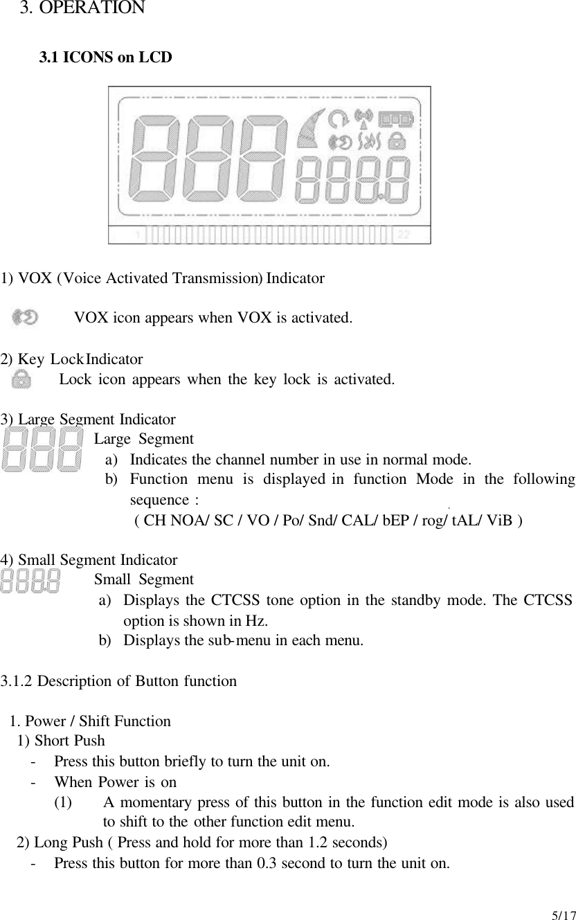
J Communications Co ATT655LE FRS/GMRS COMBINATION TRANSCEIVER User Manual ATT655LE Service Manual

J Communications Co Ltd FRS/GMRS COMBINATION TRANSCEIVER ATT655LE Service Manual

Contents

User Manual

    5/17 3. OPERATION  3.1 ICONS on LCD           1) VOX (Voice Activated Transmission) Indicator           VOX icon appears when VOX is activated.  2) Key Lock Indicator          Lock icon appears when the key lock is activated.  3) Large Segment Indicator              Large Segment a) Indicates the channel number in use in normal mode. b) Function menu is displayed in function Mode in the following sequence : ( CH NOA/ SC / VO / Po/ Snd/ CAL/ bEP / rog/ tAL/ ViB )  4) Small Segment Indicator             Small Segment a) Displays the CTCSS tone option in the standby mode. The CTCSS option is shown in Hz. b) Displays the sub-menu in each menu.  3.1.2 Description of Button function   1. Power / Shift Function 1) Short Push - Press this button briefly to turn the unit on. - When Power is on   (1) A momentary press of this button in the function edit mode is also used to shift to the other function edit menu. 2) Long Push ( Press and hold for more than 1.2 seconds) - Press this button for more than 0.3 second to turn the unit on.
    6/17 - Press this button for longer than 1.5 seconds to turn the unit off.  2. Function / Key lock Function (1) Short push - Press this button briefly to enter function edit menu or to shift to next function edit menu. - Pressing of this button in last function menu allows you to return to the stand by mode. (2) Long Push - Press for longer than 1.5 seconds to activate or inactivate in standby mode.   3. Up Key      - In the standby mode, pressing this briefly will increase volume.      - In the function edit mode, pressing the button briefly will        shift from the current option in each sub-menu to next option in        the same sub-menu.   4. Down Key    - In the standby mode, pressing this briefly will decrease volume.    - In the function edit mode, pressing the button briefly will       shift from the current option in each sub-menu to previous       option in the same sub-menu.   5. Call / Monitor Key (1) Short Push 1) Press this button in the standby mode to call another party on the same channel. 2) Press this button in function Edit mode to shift to standby mode. 3) Press this button in VOX mode to stop transmitting for 10 seconds. (2) Long Push 1) Press this button for more than 1.5 seconds in the standby mode to make channel monitoring function on or off. 2) Press this button for more than 1.5 seconds in the function edit mode to shift to the standby mode. 3) Press this button for more than 1.5 seconds in scan mode not to scan the current channel again. 4) Press this button in VOX mode to stop transmitting for 10 seconds.  6. PTT button - Press this button firmly and speak into the built-in microphone.
    7/17 3.2 Operation Method  Basic Feature 1.  Selectable 22 channel and 38 CTCSS   2.  VOX function   3.  Key Lock  3.2-1. Channel and CTCSS Code selection mode - Press the function button once in the standby mode to access a channel and CTCSS selection mode. The flashing channel number appears on the display. Press the Up or Down button to select the desired channel. - Press the Power/Shift button to select the CTCSS 2-Digit code position which flashes. Press the up or down button to select the desired sub-code.  3.2-2. VOX selection mode          - Press the function key in the Scan selection mode to access VOX           selection mode and VOX option appears flashing. - When VOX function operates, VOX icon appears.   - Press the Power/Shift button in VOX option mode to access the VOX recovery time selection mode. Select the desired VOX recovery time out of 1,2,3,5 seconds by using the up or down button. - This features allows the response time characteristics of the VOX function to be precisely adjusted to suit individual needs. - When the unit is receiving a signal, VOX function does not operate. - To turn off VOX feature, enter the VOX selection mode and then select OFF.   . 4. ADJUSTMENT 4-1. Frequency synthesizer   a) After connecting the power meter and dummy load(50 ohm), join the antenna connector of ATT-655LE with above equipment. b) Check the voltage between RF BOARD BT POINT & GND in digital volt meter c) Then set the low channel of ATT-655LE the lowest frequency. d) After pressed PTT key of ATT-655LE, check if the lowest frequency of   Tx channel to DC 1.5V in the voltage of test point(VT). e) After releasing the PTT key of  ATT-655LE, check if the highest frequency     of Rx channel is within DC 1.0V in the voltage of test point(VT).

Navigation menu