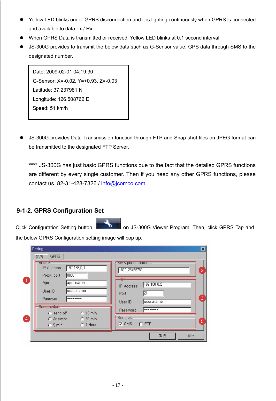
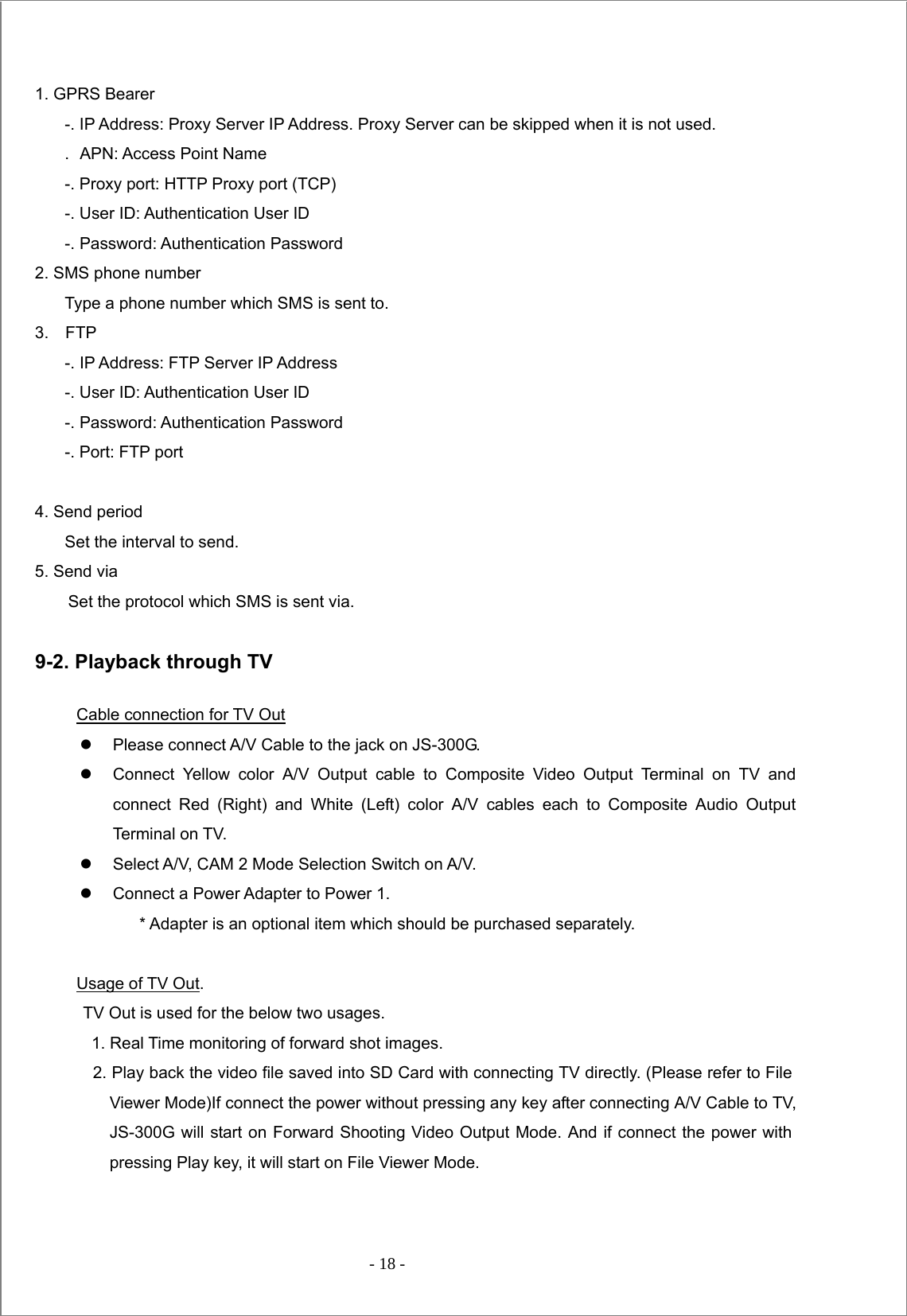
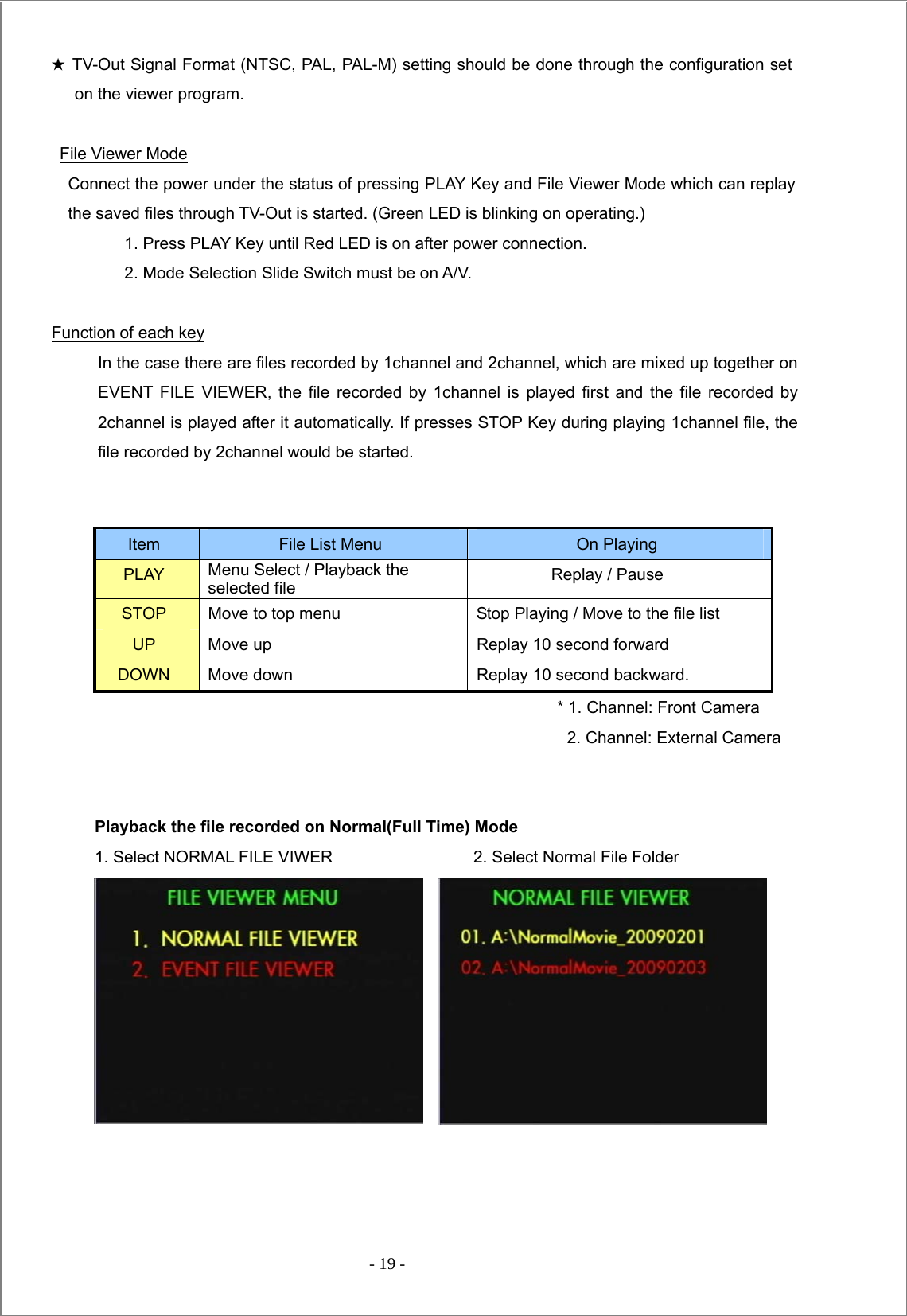
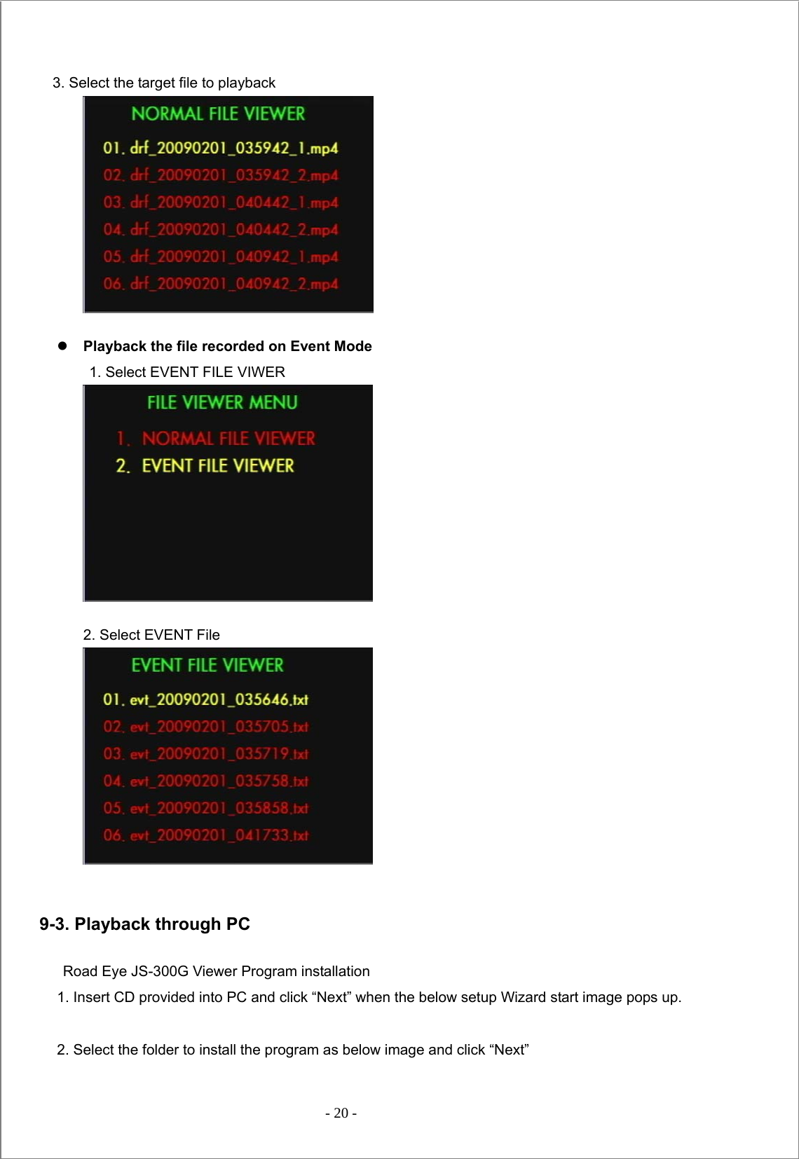
J Communications Co JS-300G PCS LICENSED TRANSMITTER (VIDEO CAR BLACKBOX) User Manual

J Communications Co Ltd PCS LICENSED TRANSMITTER (VIDEO CAR BLACKBOX)

Users Manual

 - 1 -       User Manual (Model: JS-300G)           J COMMUNICATIONS CO.,LTD.                                   Address: 124-4, Ojeon-dong, Uiwang-si, Gyeonggi-do, Republic of Korea                                   Tel: 82-31-428-7326,  Fax:82-31-451-2994  http//:www.jcomco.com
 - 2 -    Table of Contents 1. Product Introduction 2. Precautions for Safety 3. Cautions in Use 4. Specification 5. Package Contents 6. Description of Part 7. LED Signal Descriptions 8. Installation Guide   9. Function Description           10. How to use Viewer Program
 - 3 -   Terms of use The contents of this document are protected by applicable Republic of Korea and International Copyright Laws. Unless otherwise stated, the copyright owner is J COMMUNICATIONS CO.,LTD. The document and information contained within may not be copied, transmitted, reprinted, published, translated, hosted, or otherwise distributed by any means without the explicit written permission of the copyright owner.   In no event shall J COMMUNICATION CO.,LTD. its distributors or suppliers be liable to any third party for any general, special, indirect, incidental, or consequential damages whatsoever arising out of or relating to the information/ software provided in the product package.  Thanks for purchasing Road Eye, JS-300G, a driver recording system.   - Please be sure to read this manual in details before use.  - We do not provide a warranty for the compatibility of some accessories which are not provided by us.   We are also not responsible for any defect caused by such accessories. - After getting the warranty card, please check the purchasing data (Date, Shop Info) on it.   Road Eye Viewer Program which is provided is designed to be run on Window 2000/XP/Vista.  Warning! Road Eye is a device to assist a safety driver.   We are neither responsible nor compensate for any defect and damage caused by user’s misuse and carelessness.    CAUTION                                  Danger of explosion if battery is incorrectly replaced.                                    replace only with the same or equivalent type.
 - 4 -  1. Product Introduction Road Eye is a Driver Recording System which applies GPS (Global Positioning System), GPRS and 3D acceleration gravity sensor (G-Sensor).   Before using this product, please be sure to read this manual.   Actual product specifications may differ from what is indicated in this manual as product enhancements are implemented without prior notice.   Printed at the time of production, this manual may contain technical or editorial mistakes or omission.  2. Precautions for Safety To prevent causing damage to the user’s property and to ensure the user’s safety, please read carefully           the following precautions.  While driving, never perform any operation and always park the car in a safe place first before operating the device.    Do not disassemble, repair, or reconstruct without an authorized technician.      Use the device under proper temperature.   Leaving the device for a long time under hot or cold temperature can be a cause of malfunction. (Proper Temperature: 0 ~ 60℃)   Avoid exposing this product to shock or impact and keep it away from magnetic fields or vibration. Keep the product away from wet places.    In using vehicle power, do not use for a long time with the engine off. It may be a cause of discharge.
 - 5 -  This product is designed to be used with Cigar Jack Power. In case of using direct electric power (B+ Power) of car, please discuss with a specialist, and any problem occurred in this case will belong to users responsibility.     3. Cautions in Use  3-1. Cautions   z  Performing while driving can be a cause of accident. Always park the car in a safe place first before operating the device.   z  Check the installation status before driving. Driving under the physical conditions such as uneven, a sharp curve in the road with unstable installation might cause damage.   z  In using vehicle power, please first check if there is no problem with the power supply before connecting the device to the cigar jack adaptor. Any sudden power spike may damage the device.   z    This product is designed to automatically record a video file, triggered by a user-defined level impact to your car. The manufacturer does not guarantee about every impacts on your car to trigger this function.   z  Prevent any foreign substance to come in contact with the memory card or the internal parts of this device, as it might cause malfunctions. Keep the lens clean and avoid any obstacles in the camera angle to get the clear view.   z  Do not put other substances around the device. It can be mirrored through the windows and recorded with accident images.
 - 6 -  z  In the accident getting less impact than the minimum user defined, the image may not be recorded. (Refer to the manual)  z  Rights of all the software and hardware related to this product belong to    J COMMUNICATIONS CO., LTD. Unauthorized reproduction, processing and distributing can be punished by intellectual property rights management law as well as claimed compensation for damages.
 - 7 -    4. Specification  Front Camera  120° ⅓” CMOS 300K Pixel Digital Sensor / WDR Support External Camera  Option (90° ¼” CCD 270K Pixel NTSC) Recording Resolution H.264 (VGA 640*480 up to 30fps) ★ 2ch use : VGA 640*480 up to 15fps GPS  Internal GPS Shock Sensor  Internal 3D G-Sensor Storage  SD Memory Card (1GB ~ 16GB) Audio  Internal MIC Power  DC 12V ~ 24V (From Car adaptor) File Saving  Upon Impact (Automatic/Manual) Normal Recording (Full Time)  Support Real Time Clock  Support TV-Out   Support Size   119.5(L) mm x 55(W) mm x 31.7(D) mm          Weight (g)   157g
 - 8 -  5. Package Contents Please check the contents after opening the gift box. (Refer to the below images)                                   JS-300G        Cigar Jack Power Cable         SD Memory Card                  User Manual             Viewer Program CD               A/V Cable (For TV Connection)       Cable Tie / Holder      GPRS Ant (Only for JS-300G)                      External Camera & Cable (Option)  (Actual product specifications may differ from the images in this manual as product enhancements are implemented without prior notice.)
 - 9 -  1.TV Out Jack (A/V Mode) 2.External Camera Video In Jack 6. Description of Part                                       SIM Card Slot (Only for JS-300G) RED: Event Mode GREEN: Normal Mode Front Camera Main Power External Double Faced Foam Tape GPRS Antenna Jack Lock SD Card Emergency Mode Selection Switch 1. A/V : TV Out 2. External Camera Function Reset YELLOW: GPRS(Only for BLUE:
 - 10 -   7. LED Signal Descriptions  Classification RED (Event)GREEN (Full Time) YELLOW (GPRS) BLUE(GPS)Status Power connecting    ( With SD Card )  ○    ○ ○ Blinking at 1 sec interval one after another. Power Connecting    (Without SD Card)  ○ ○      Blinking at 0.5 sec interval by turns Stand by Event Recording  ○        Blinking at 1 Sec interval When Event occurs ( Or when press Emergency Key) ○        Blinking at 0.1 Sec interval for 3 seconds On Normal(Full Time) Recording   ○      Blinking at 1 Sec interval When GPS signal is available          ○ Blinking at 1 Sec interval When GPS signal is not available        ○ Light on continuously When calibrates G-Sensor  ○        Blinking at 0.1 Sec interval for a secondFirmware Upgrade ( When Power is connected )  ○    ○ ○ Light on at 1 sec interval rapidly by turns Firmware Upgrade (On progress )   ○      Blinking at 0.1sec rapidly Firmware Upgrade (Completed)   ○ ○ ○ Light on at the same time File Viewer ( When connected )  ○        Light off after lighting File Viewer ( When runs )   ○      Light on continuously When searches GPRS Network      ○    Blinking at 1 Sec interval When GPRS Network is connected      ○    Light on continuously When transmits GPRS Data      ○    Blinking at 0.1 Sec interval System Error  ○ ○      Light on continuously (with Orange color)
 - 11 -  8. Installation Guide    8-1 .PRECAUTIONS  z  Turn off the engine before installation.   Connect the main power of the device at last after installation. ( , here in after called “Power”) z  Insert SD Memory card before connecting the device. z  Install the device in safe and bright place. z  Connect the main power through cigar jack provided (DC 12V ~ 24V).  8-2. Installation                            1. Attach the device Check and select the proper place where does not disturb driving on the front window and attach the device with a double faced tape.2. Fix the device Get the camera lens focused on the front and fix with Lock Screws of the device. ★ GPS reception part should be exposed to the window for the better reception. 3. Connect the power Connect the cigar jack to the power port and check if the power is working properly. ★ SD Card should be inserted before connecting the power. Otherwise, Red and Green LED would be blinking at 0.5sec interval by turns. 4. Calibrate G-Sensor (Acceleration Sensor) Press “Down” for 3 seconds when power is on, and calibrate G-Sensor value. (Check if Red LED is blinking at 0.1sec interval rapidly for a second.) ★ When calibrates G-Sensor, put the device on flat place.   When changes the place to attach the device, calibrating should be
 - 12 -      Checkups after installation          External Camera Installation (Option)  1 Select a place to install Select a place to install the external camera and fix with the screw provided.   (The connecting part should be toward to the ground.)  2 Connect the camera to JS-300G Connect the camera to JS-300G with the cable provided. (    , A/V)     3 Fix the camera angle After adjusting camera angle, fix the camera with the lock screws on the bracket.   ★ Disconnect the power during installation of the camera. ★ External Camera is only for internal use.    5. Working Test   Play back the saved data after testing drive. Then, check if the data is recorded correctly and revise the camera place on it. ★ JS-300G is working based on High- Sensitivity Camera Sensor.   The recorded video image can be shown dark if the device is installed toward the sky. 1. If the camera angle is not proper, adjust with rotating the lock screw and fix it after. (Refer to the step 2 ~ 5).
 - 13 -  8-3. Start  1.  Insert SD Card into JS-300G, then power on. Red, Yellow and Blue LED will light sequentially   at a second interval. about 3 seconds after lighting, JS-300G will start running.         If it powers on without SD Card, Red and Green LED will be blinking alternately at 0.5 sec interval.             In this case, disconnect the power and connect power again after inserting SD Card.    2. Recording is run based on Event and Normal record mode (Full Time Mode), and the present          recording mode is saved and memorized into Configuration Variable Setting File in SD Card.   (The Factory default record mode is Event Mode and it would be same after formatting SD Card.)  3. To change the recording mode, connect power under the status of pressing Emergency key simultaneously.             The mode will be changed either Event Record mode to Normal Record Mode or Normal Record mode to Event Record Mode.             The changed recording Mode would be saved into SD Card and maintained until the mode is changed by user. When press Emergency Key, just press it until Red LED turns on.    8-4. Event Record Mode  1. During Event Record Mode, Red LED is blinking at a second interval.    2. When the impact value recognized by G-Sensor (Acceleration sensor) is bigger than User-defined value or when user presses Emergency key manually, the image and voice before 10 seconds and after 20 seconds of the event will be saved as a file. When an event occurs, Red LED will be blinking rapidly at 0.1 second interval for 3 second and inform of it.    3. Another event occurs while the previous event is saved, the event would be ignored.        (If emergency record is required, just press Emergency button and recording will be started. After recording, the mode will be back to Event Record Mode.)          Event can be recorded up to 100 times as a file, and from the file recorded first it would be over written sequentially when the number of file is exceeding the maximum.         4. When the power is disconnected on Event Record Mode, JS-300G would be shutdown after saving the event, maximum 20 seconds, if it is on recording an event. Otherwise it will be shutdown instantly.  5. If presses Stop Key, JS-300G will complete recording event and all functions will be stopped. (All LED lights will be off) to start JS-300G again, disconnect power and connect again.
 - 14 -   8-5. Normal Record Mode (Full Time Recording)  1. Green LED is blinking at a second interval on Normal Record Mode.   2. Normal Record Mode records video and audio at 5 minute interval successively.   3. If SD Card storage is full during Normal Mode, JS-300G will overwrite from the file saved first.   4. During Normal Mode, G-Sensor (Acceleration Sensor) and Emergency Key function will be ignored.   5. If power is disconnected during Normal Mode, JS-300G will be shutdown after 10 second        additional recording. If presses STOP Key on Normal Record Mode, JS-300G will complete           recording and all functions will be stopped. (All LED light will be off). To start JS-300G again, disconnect       power and connect again.    8-6. Reset  1. There can be unexpected system errors. If the error occurs, Green and Red LED light columns are on                     at the same time and lighting on Orange color continuously. 2. When system error occurs, disconnect power. Then press Reset key with the pointed stuff such as a pin,                 a ballpoint pen…etc., and connect power again. JS-300G will be re-booting and run.  8-7. GPS Functions 1. If GPS data is not received properly, Blue LED will blink at a second interval.    When GPS Data reception is working properly, Blue LED will be lighting continuously. 2. If presses Play Key on either Normal Record Mode or Event Record Mode for more than 3 seconds, GPS Cold Start will be operated with Blue LED blinking rapidly at 0.1 second for a second. 3. If GPS Data reception is running correct, set the time of internal RTC (Real Time Clock) on GPS time. Once set on GPS time, it will maintain the exact time without any additional time set. The internal RTC time is reflected with connecting the power again after power disconnection. 4. If there is any substance which can give the bad effect to GPS reception, please leave it in the distance from JS-300G    8-8. Acceleration Calibration Function z  G-Sensor (Acceleration Sensor) shows the Acceleration Value of X, Y and Z axis on the unit of acceleration of gravity, 1g = 9.8m/s2. And the directions are as below image.  If a vehicle is parked on the flat place, G-Sensor data is supposed to have the value of X = 0g, Y = 0g and Z = +1g. However, it would be changed by the place JS-300G is placed and mounted. Thus G-Sensor should be calibrated to get more exact data.
 - 15 -   z  If presses Down Key on either Normal Record Mode or Event Record Mode for more than 3 seconds, Calibration will be operated with Red LED blinking rapidly at 0.1 second for a second.  After the calibration, G-Sensor Data will show the value, X = 0g, Y = 0g and Z = +1g, regardless of the mounting place. Â G-Sensor Calibration must be done on the flat place after parking.     G- Sensor Data Analysis (Example) Viewer Program shows G-Sensor Data Graph as the below images upon Log Data which is saved with video files and driving status can be analyzed through the graph.         Stop                         Acceleration                                           Deceleration                        Right Turn                                                Left Turn
 - 16 -                          Head-On Collision                                     Back-Up Collision  9. Function Description  9-1. GPRS Functions   (GPRS Function is only for JS-300G) 9-1-1. GPRS Specification z  Used band: Quad-band (E-GSM 850 / 900 / DCS1800 / PCS1900 MHz) z  Operated Frequency ;   -. EU (Up link: 880.200 MHz ~ 914.800 MHz ,    1 710.200 MHz ~1 784.800 MHz)        (Down link: 925.200 MHz ~ 959.800 MHz,    1 805.200 MHz ~ 1 879.800 MHz)   -.FCC(Up link: 824.200 MHz ~ 848.800 MHz ,      1 850.200 MHz ~1 909.800 MHz)          (Down link: 869.200 MHz ~ 893.800 MHz,    1 930.200 MHz ~ 1 989.800 MHz) z  Output power ;   Max.13dBm(20 mW)_Conducted power including antenna gain, declared by the applicant z  Communication Access Type : TDMA (Time Division Multiple Access) z  Channel spacing : 200 KHz z Channel Number ;            -. EU(900 MHz Band : 172 Ch,      1 800 MHz Band : 373 Ch)            -.FCC(850 MHz Band : 123 Ch,    1 900 MHz Band : 298 Ch) z  Communication Type : Full duplex   z  Data Rate (kbps): 57.6   kbps z  Data Modulation : GMSK z  ITU emission Code : 290KGXW z Antenna type and Length ;   -.Type: Dipole Antenna,    Gain : 824~960 MHz (1.4 dBi),    1 710~1 990 MHz (0.2 dBi) Length: 104.8 mm z  Weight & Size : 157g / 119.5(L) mm x 55(W) mm x 31.7(D) mm z Power rating : DC 12V ~ 24V (from External Car Adapter), 2 A z Sensitivity - 107 dBm (typ.) @850 / 900 MHz,    106 dBm (typ.) @ 1800 / 1900 MHz
 - 17 -  z  Yellow LED blinks under GPRS disconnection and it is lighting continuously when GPRS is connected and available to data Tx / Rx.   z  When GPRS Data is transmitted or received, Yellow LED blinks at 0.1 second interval.   z  JS-300G provides to transmit the below data such as G-Sensor value, GPS data through SMS to the designated number.         z  JS-300G provides Data Transmission function through FTP and Snap shot files on JPEG format can be transmitted to the designated FTP Server.    **** JS-300G has just basic GPRS functions due to the fact that the detailed GPRS functions are different by every single customer. Then if you need any other GPRS functions, please contact us. 82-31-428-7326 / info@jcomco.com    9-1-2. GPRS Configuration Set Click Configuration Setting button,   on JS-300G Viewer Program. Then, click GPRS Tap and the below GPRS Configuration setting image will pop up.               Date: 2009-02-01 04:19:30 G-Sensor: X=-0.02, Y=+0.93, Z=-0.03 Latitude: 37.237981 N Longitude: 126.508762 E Speed: 51 km/h
 - 18 -   1. GPRS Bearer -. IP Address: Proxy Server IP Address. Proxy Server can be skipped when it is not used. .  APN: Access Point Name -. Proxy port: HTTP Proxy port (TCP) -. User ID: Authentication User ID -. Password: Authentication Password 2. SMS phone number Type a phone number which SMS is sent to.   3.  FTP -. IP Address: FTP Server IP Address -. User ID: Authentication User ID -. Password: Authentication Password -. Port: FTP port  4. Send period Set the interval to send. 5. Send via         Set the protocol which SMS is sent via.  9-2. Playback through TV Cable connection for TV Out z  Please connect A/V Cable to the jack on JS-300G. z  Connect Yellow color A/V Output cable to Composite Video Output Terminal on TV and connect Red (Right) and White (Left) color A/V cables each to Composite Audio Output Terminal on TV. z  Select A/V, CAM 2 Mode Selection Switch on A/V. z  Connect a Power Adapter to Power 1.             * Adapter is an optional item which should be purchased separately.    Usage of TV Out. TV Out is used for the below two usages.       1. Real Time monitoring of forward shot images.     2. Play back the video file saved into SD Card with connecting TV directly. (Please refer to File Viewer Mode)If connect the power without pressing any key after connecting A/V Cable to TV,   JS-300G will start on Forward Shooting Video Output Mode. And if connect the power with pressing Play key, it will start on File Viewer Mode.
 - 19 -  ★ TV-Out Signal Format (NTSC, PAL, PAL-M) setting should be done through the configuration set on the viewer program.  File Viewer Mode Connect the power under the status of pressing PLAY Key and File Viewer Mode which can replay the saved files through TV-Out is started. (Green LED is blinking on operating.) 1. Press PLAY Key until Red LED is on after power connection.   2. Mode Selection Slide Switch must be on A/V.    Function of each key In the case there are files recorded by 1channel and 2channel, which are mixed up together on EVENT FILE VIEWER, the file recorded by 1channel is played first and the file recorded by 2channel is played after it automatically. If presses STOP Key during playing 1channel file, the file recorded by 2channel would be started.     Item  File List Menu  On Playing PLAY  Menu Select / Playback the selected file    Replay / Pause STOP  Move to top menu  Stop Playing / Move to the file list UP  Move up  Replay 10 second forward DOWN  Move down  Replay 10 second backward. * 1. Channel: Front Camera                                                          2. Channel: External Camera    Playback the file recorded on Normal(Full Time) Mode   1. Select NORMAL FILE VIWER                 2. Select Normal File Folder
 - 20 -   3. Select the target file to playback            z Playback the file recorded on Event Mode   1. Select EVENT FILE VIWER                                      2. Select EVENT File           9-3. Playback through PC  Road Eye JS-300G Viewer Program installation 1. Insert CD provided into PC and click “Next” when the below setup Wizard start image pops up.  2. Select the folder to install the program as below image and click “Next”
 - 21 -     3. Select Start Menu folder and press “Next” button.
 - 22 -   4. Press “Next” button when the below image pops up.   5. Press “Install” button to install the program when the below image pops up.
 - 23 -  6. When the installation is completed, the below image pops up. Then, press “Finish” button to finish  the process.
 - 24 -  Codec Installation To play back the files recorded through JS-300G Viewer program, K-Lite codec provided with a bundle CD must be installed.  1. Double click Klcode475b.exe file on CD and start the installation.   Press “Next” button when the below image pops up.   2. Press “Next” button when the below image pops up.  3. Press “Next” button when the below image pops up.
 - 25 -   4. Press “Next” button when the below image pops up.   5. Press “Next” button when the below image pops up.   6. Press “Next” button when the below image pops up.
 - 26 -  7. Press “Next” button when the below image pops up.   8. When the installation is completed, the below image pops up. Then, press “Finish” button to finish  the process.
 - 27 -    10. How to use Viewer Program             - Double click Viewer Program Icon . - Viewer Program Main Screen                   c Playback Display d Slide Bar: It shows a play back progress and users can start play back a file on a specific part with moving it. e G-Sensor Graph: It shows G-Sensor data with graphs. f Menu Button g Speedometer and Compass h Google Map: Users can track the driving route with GPS location data saved with the video file through this map. i Playback list   j Indicates the video file route currently played.   k Additional Information Display: It shows additional GPS and G-Sensor information.
 - 28 -  Menu Button and Control   Google Map Control    Button and Control  Function  Description  Volume Control  It controls the play volume.  Stop  Stop playing and back to the start of the playing file.  Previous  Play the previous file when selects the plural files and views in series.  Play / Pause  Press this key to pause during playing. Press once again to back to play.  Next   Play the next file when selects the plural files and views in series.  Full Screen  Playback on Full size screen. ★ To be back to the standard screen size, double click Full size screen or press ESC.  Playback Speed Control It controls the speed of playing, either slower or faster.  Report Print Out  Making a reporting file with Snap shot image, G-Sensor Graph and Map…etc.  Configuration Set  Setting Operating configuration  Program Information  Shows the current Program Version Information Control  Function  Map Tracking, Map Zoom In / Out ★ Satellite Map view is providing smaller scale than Normal Map View.  Select Normal Map View / Satellite Map View / Overlay Map View
 - 29 -    Play List Button and Control    Other Buttons            Button and Control  Function  Description  Open Folder  It selects the folder to play.  Delete  It deletes the selected file and G-Sensor, GPS Log file which were saved together. ★ In the case of the file recorded by 2channel, it would deletes the file recorded by 1channel together.  File recorded on Normal Mode / File recorded on Event Mode It selects and lists the files recorded on Normal Mode / Event Mode.  Camera Channel Select filter  It selects and lists the selected camera file when playbacks the file recorded by 2channel. Button and Control  Function  Description     Open /Close additional information screen   It opens or closes the additional information screen which shows the additional GPS and G-Sensor information.  Minimize  / Close Window
 - 30 -   Playback Movie File z Playback a single file 1.    Select a target root folder in SD or PC with clicking Open Folder   on Playback List screen.  2.    Select a target file to play on the file list and double click.   Â After selecting a file on the list, Playback button   can be pressed to play.  z Continuous Playback with plural files   1.  Select a target root folder in SD or PC with clicking Open Folder    on Playback List screen. 2.  Select a target file to play first and click. 3.  Select the target files to play, and click with pressing CTRL key at the same time.   (To release the selection, click again with pressing CTRL at the same time.)   If clicks the first file and clicks the last file to view with pressing SHIFT Key at the same time, all the files from the first to the last to view would be selected successively.   To select all files, press CTRL + A key. 4.  Click Playback Button    and start the continuous play.  ★    In order to playback the movie files through the viewer Program, either connect SD Card to PC or copy all the folders and files stored in SD Card into PC.
 - 31 -    Configuration Set Click Configuration Set button and the below configuration image will pop up.                    1.  G-Sensor Trigger Level: Set the sensitivity of G-Sensor.   Move the slide bar and select the value between 0.10 ~ 0.99. (Default Value: 0.50)   (0.30: Sensitive, 0.50: Normal, 0.70: Dull) 2.  Audio Recording:   Select Voice Recording availability, ON or OFF.    (Default: ON) 3.  Unit of Speed: Select a unit of speed. (Default: km/h) 4.  TV-Out: Select TV Output format. (Default: NTSC) 5.  Time Zone Setting: Set the time zone of user. (Default: Korea GMT+09:00)  UPDATE -Firmware Update -SD Card Data  ▣Firmware Update  JS-300G is firmware upgradeable through SD Card.  1. Copy the target file to update, “app.bin” into a root folder of SD Card.
 - 32 -   2. Insert SD Card into JS-300G and connect the power.  3. When Red, Yellow and Blue LED is sequentially on at a second interval and JS- 300G is started, Update is progressed with Green LED blinking rapidly at 0.1 second interval.    4. When Update is completed, Green, Yellow and Blue LED are on at the same time.  5. Disconnect the power and connect again. JS-300G is working based on the new firmware.  ★ More information, please refer to www.jcomco.com  ▣SD Card Data 1. Event Folder     On the Event Record Mode, JS-300G is recording the time, file name, G-Sensor Data and GPS Data and save it on the name of “evt_yyyymmdd_hhmmss.txt” when the event occurs.    2. Event Movie Folder     On the Event Record Mode, JS-300G records for the maximum 30 seconds of video and audio and save it on the name of “evt_yyyymmdd_hhmmss_1.mp4” in this folder when the event occurs. (“evt_yyyymmdd_hhmmss_2.mp4” for 2channel)        Event Movie\Acc Folder     G-Sensor Log on the Event Record Mode is saved on the name of “acc_yyyymmdd_hhmmss.txt” in this folder.    Event Movie\Gps Folder    GPS Log on the Event Record Mode is saved on the name of “gps_yyyymmdd_hhmmss.txt” in this folder.  3. Normal Movie_yyyy mm dd Folder   On the Normal Record Mode, JS-300G records video and audio and saves it on the name of “drf_yyyymmdd_hhmmss_1.mp4” in this folder. (“drf_yyyymmdd_hhmmss_2.mp4” for 2channel) When the saved file number in the folder is reaching to 100th, another new folder is created and the file from the 101st is saved into the new folder.        Normal Movie_yyyy mmd d \Acc Folder     G-Sensor Log on the Normal Record Mode is saved on the name of “acc_yyyymmdd_hhmmss.txt” in this folder.
 - 33 -       Normal Movie_yyyy mm dd \Gps Folder     GPS Log on the Normal Record Mode is saved on the name of “gps_yyyymmdd_hhmmss.txt” in this folder.  4. Setup Folder     Environment Variables and G-Sensor Calibration Data files are saved into this folder.  5. Temp Folder     This is a folder to save the temporary files for GPRS functions.
 - 34 -  11. LIMITED WARRANTY STATEMENT This Limited Warranty shall apply to the JCOM Product including all accessories as contained within the original JCOM gift box (“the Product”). J Communications Co., Ltd. (JCOM) warrants that product from its authorized distributor will meet the applicable product specifications and be free from all defects in material and workmanship for an applicable period herein (“Limited Warranty”). This Limited Warranty is subjected to the following terms and conditions: 1. This Limited Warranty is given only to the original purchaser of the Product (“Customer”) it shall neither exclude nor limit a) any statutory rights of the Customer or b) any of the Customer’s rights against the sellers of the Product. 2. The Limited Warranty shall be restricted to the country/region of Product purchase this is to avoid excessive import or exportation of the Product throughout the supported countries. 3. This Limited Warranty is only valid and enforceable in countries where the Product is sold. Outside of the country of purchase, any repairs performed by JCOM’s Authorized Service Centre are subject to charge to the purchaser at normal repair rates. 4. The Limited Warranty entitles the Customer to a Product replacement or a full refund of the purchase price for any defects relating to the performance and/or functioning of the Product which result from normal use of the Product, provided that such a defect arises within ten (10) days of the original date of purchase of the Product and cannot be otherwise repaired. JCOM will provide a replacement or repair of the Product at JCOM’s own expense for any such defect arising after ten (10) days but within one (1) month of the original date of purchase. This Limited Warranty may not be sold – on, assigned, transferred or given to any subsequent purchaser or acquirer of the Product. 5. This Limited Warranty shall last for twelve (12) months from the date of original purchase (“Warranty Period”). avalid original invoice (“Proof of Purchase”) is required. 6. This Limited Warranty covers expenses for inspecting and repairing the Product during the term of the Limited Warranty. Customer shall deliver the defective Product to the JCOM-designated premises together with the warranty certificate, proof of purchase, and proof of identity of the Customer; however, any defective Product shipped by the Customer missing any one of such documentation may render this Limited Warranty invalid. Where the defect was the result of the Customer’s own mishandling of the Product, force major, or the result of a repair by an unauthorized service provider, the Customer shall bear all expenses relating to shipping such a defective Product. 7 JCOM will return the repaired Product or another Product to the drop-zone for collection by the Customer in good working condition. All replaced faulty Products or components thereof will become the property of JCOM. 8. This Limited Warranty applies only to the original hardware components of the Product and does not apply to any software or other equipment. 9. If J COM’s repairs or replaces the Product, the repaired or replaced Product shall continue to be warranted for the remaining term of the Limited Warranty period or for three (3) months from the date of repair or replacement, whichever is longer.
 - 35 -   10. Before returning any units for service, the Customer is solely responsible for backing up data and removing any confidential, proprietary, or personal information from the Product. JCOM’s is not responsible for damage to or loss of any programs, data, or removal storage media. 11. This Warranty does NOT cover recovery from any software updates, installation and removal of the application software, or any loss of data storage. 12. JCOM reserves the right to add, delete or amend the terms and conditions of this Limited Liability and any such change will be made available to the purchasers of the Product either on JCOM’s Web site (http://www.Jcomco.com) or by other means. 13. THIS LIMITED WARRANTY SHALL NOT APPLY IF THE DEFECT WAS CAUSED THROUGH ANY OF THE FOLLOWING: (a) The Product serial number, the accessory date code has been removed, erased, defaced, altered or is illegible; or (b) The defect is resulting from the use of the product in a manner other than their normal and customary manner, e.g., in excess of their minimum specification or operating instructions, or malfunction or failure resulting from use of in calibrate voltages; or (c) Deterioration of the Product due to normal wear and tear. All plastic surfaces and other natural wear of externally exposed parts of the product are scratched or damaged under normal usage; or  (d) The defect is arising from improper installation, unauthorized repair, alteration or modification to the Product by third parties; or (e) The defect is arising from operating with components or accessories (ancillary or peripheral equipment) not officially authorized or provided by JCOM or used in other than its intended use; or (g) The defect or damage are arising from unauthorized modification; or (h) The defect or damage is arising from misuse, mishandling, accidental lost, abuse, accident, negligence and damage caused directly or indirectly by Customer, including but not limited to improper testing, installation, alteration or modification of any kind, or spillage of food or liquid, or build up of dirt or dust, or mains supply problem, thunderstorm activities, or infestation by insects or vermin, or exposure to abnormally corrosive conditions, or operation with extreme heat or humidity; or 14. WHERE A DEFECT WAS UNDETECTABLE BY THEN-AVAILABLE TECHNOLOGY OR WAS THE RESULT OF COMPLYING WITH THE APPLICABLE REGULATORY STANDARDS OR WHERE THE DEFECT WAS THE RESULT OF THE CHANGE IN THE DESIGN OF THE PRODUCT COMPONENTS SUPPLIED BY A THIRD PARTY, JCOM WILL NOT BE LIABLE FOR ANY LOSSES OR DAMAGES OF ANY NATURE 15. This Limited Warranty, INCLUDING BUT NOT LIMITED TO LOST PROFITS OR COMMERCIAL LOSS OF THE CUSTOMER. does not affect the Customer’s statutory rights in law specific to the country of purchase, and such rights remain protected. Some countries do not allow the exclusion
 - 36 -  or limitation of incidental or consequential loss or damage, or limitation of the implied warranties, in which case the preceding limitation of exclusions may not apply to such Customers.  Please note Warranty service availability and response times may vary from country to country and may also be subject to registration requirement in the country of purchase. If you require assistance regarding warranty conditions, or have any other inquiries, please contact the JCOM Customer Care Center or via the official website: www.jcomco.com.  Product Warranty Period JS-300G  Car Black Box System 1 year from purchase     Technical Support  If you have any questions or suggest, please contact the following addresses.   Contact our support team from 09:00 to 18:00 Monday through Friday.   TEL : 82-31- 428-7326        FAX : 82-31- 451-2994   Website :www.Jcomco.com    E – mail : Info@Jcomco.com

Navigation menu