J and M HS-BLU Bluetooth Device User Manual HS BLU277 qxp
J&M; Corporation Bluetooth Device HS BLU277 qxp
J and M >
User Manual
Bluetooth Helmet
Headset
#HS-BLU277 Series
© 2007 J&M Corporation. All rights reserved. 6/06
Owner’s Manual

1. Product Description
The HS-BLU277 is a high audio output, true stereo Bluetooth
wireless helmet headset that will link to most Bluetooth enabled
audio devices available today. This lightweight unit also features
a plug for connecting to passenger’s standard J&M dual mode
helmet headset for seamless and simultaneous driver/passen-
ger communications. The HS-BLU277 is powered by a recharge-
able lithium ion/polymer power cell.
2. Safety and General Information
IMPORTANT INFORMATION OF SAFE AND EFFICIENT OPERA-
TION. READ THIS INFORMATION BEFORE USING YOUR DEVICE.
Users are not permitted to make changes or modify the device
in any way. Changes or modifications not expressly approved by
the party responsible for compliance could void the user’s
authority to operate the equipment. See 47 CFR Sec. 15.21.
This device complies with part 15 of the FCC Rules. Operation is
subject to the following two conditions: (1) This device may not
cause harmful interference, and (2) this device must accept any
interference received, including interference that may cause
undesired operation. See 47 CFR Sec. 15.19 (3).
ELECTROMAGNETIC INTERFERENCE/COMPATIBILITY
Note: Nearly every electronic device is suspectible to electro-
magnetic interference (EMI) if inadequately shielded, designed or
otherwise configured for electromagnetic compatibility.
FACILITIES
To avoid electromagnetic interference and/or compatibility con-
flicts, turn off your device in any facility where posted notices
instruct you to do so. Hospitals or health care facilities may be
using equipment that is sensitive to external RF energy.
AIRCRAFT
When instructed to do so, turn off your device when on board an
aircraft. Any use of a device must be in accordance with applica-
ble regulations per airline crew instructions.
MEDICAL DEVICES
HEARING AIDS
Some devices may interfere with some hearing aids. In the event
of such interference, you may want to consult with your hearing
aid manufacturer to discuss alternatives.
OTHER MEDICAL DEVICES
If you use any other personal medical device, consult the manu-
facturer of the device to determine if it is adequately shielded
from RF energy. Your physician may be able to assist you in
obtaining this information.
Industry Canada Notice to Users
Operation is subject to the following two conditions: (1) This
device may not cause interference and (2) This device must
accept any interference, including interference that may cause
undesired operation of the device.
FCC Notice to Users
This equipment has been tested and found to comply with the
limits for a Class B digital device, pursuant to part 15 of the
FCC Rules. These limits are designed to provide reasonable pro-
tection against harmful interference in a residential installation.
This equipment generates, uses and can radiate radio frequency
energy and, if not installed and used in accordance with the
instructions, may cause harmful interference to radio communi-
cations. However, there is no guarantee that interference will not
occur in a particular installation. If this equipment does cause
harmful interference to radio or television reception, which can
be determined by turning the equipment off and on, the user is
encouraged to try to correct the interference by one or more of
the following measures:
• Reorient or relocate the receiving antenna.
• Increase the separation between the equipment and the
receiver.
• Connect the equipment to an outlet on a circuit different
from that to which the receiver is connected.
• Consult the dealer or an experienced radio/TV technician
for help.
3. Performance Features
•High Audio Output
•True Two Channel Stereo
•Integrated Rider-Passenger Intercom
•Separate Bluetooth and Intercom Volume Controls
•HSP (Headset Profile)
•HFP (Handsfree Profile)
•A2DP (Advanced Audio Distribution Profile ((Streaming
Stereo))
•AVRCP (Audio Video Remote Control Profile)
4. Package Contents
• HS-BLU277 Head Unit
• Lithium Ion/Polymer Power Cell
• AC Battery Charger
• Two Speakers
• Microphone
• Clamp Assembly
• Velcro
• Owner’s Manual
Product Description Section 1
Safety & General Information Section 2
Performance Features Section 3
Package Contents Section 4
Controls and Functions Section 5
Installation Instructions For Section 6A
Full Coverage & Flip Front
Style Helmets
Installation Instructions For Section 6B
3/4 Style Helmets
Operation Instructions Section 7
Table of Contents
POWER
LINKED/
PAIRING
P
O
W
E
R
O
N
/
O
F
F
MULTIFUNCTION
I
N
T
V
O
L
A
BC D
E
F
G
H
I
J
K
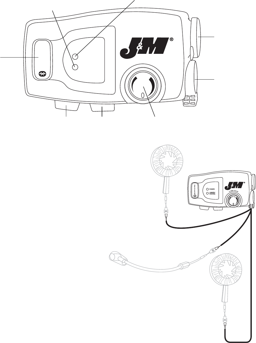
5. Controls and Functions
A. Multifunction Button – Used for turning on/off Bluetooth, pairing
mode for Bluetooth, answering cell phone, and other multifunction
features.
B. Bluetooth Volume Up – Allows Bluetooth volume up adjustment.
C. Bluetooth Volume Down – Allows Bluetooth volume down adjustment.
D. Power On/Off Intercom Volume – Turns the entire unit on and off and
allows control of the intercom volume.
E. Driver Helmet Headset Speakers and Microphone – The connectors
that are on this cord connect to the drivers helmet headset speakers
and mike.
F. Passenger Headset Jack – A passenger can plug into
this plug using a standard J&M dual mode helmet
headset, with the correct lower section cord. This
plug is also used to charge the lithium ion/polymer
power cell with charger adapter.
G. Power LED – This LED illuminates red when the
power on/off switch is in the on position.
H. Linked/Pairing LED – This LED illuminates blue when the Bluetooth
part of the headset has been turned on. This LED will flash slowly or
rapidly depending on the function that is chosen. This LED will illumi-
nate red when connected to the battery charger.
I. Left Speaker Connector – Connects to left speaker.
J. Microphone Connector – Connects to boom or chin bar style
microphone.
K. Right Speaker Connector – Connects to right speaker.
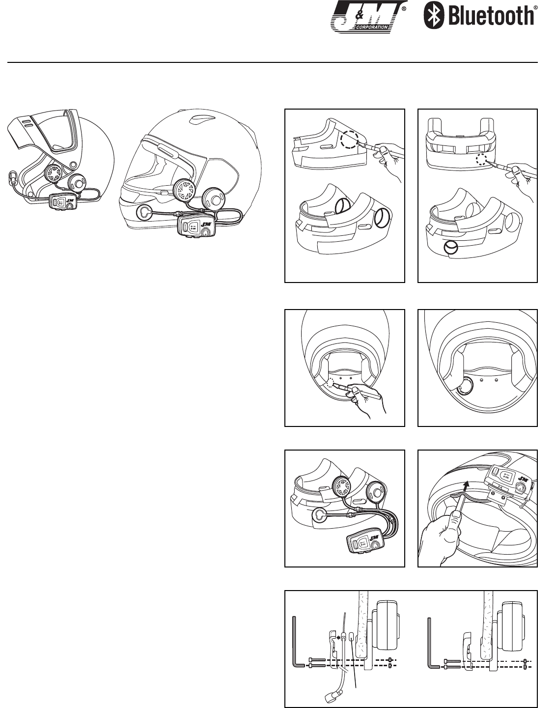
Installation into Full-Coverage & Flip-front Style Helmets
The full-coverage type of helmet presents special challenges for headset instal-
lation. If you do not feel you are up to the task, you may send your "un-modi-
fied" helmet to our factory in Tucson and we will perform the installation for a
nominal fee. (Please call first to insure that J&M is able to install a headset
into your particular brand/model of helmet.)
1. Most full coverage-style helmets have cheek pads or a complete nose sec-
tion that can be removed. Carefully do so at this time, paying special attention
so as not to break or damage any of the polystyrene parts.
2. Using a headset speaker as a guide, mark the circular pieces of styrene to
be removed from the back of the ear area of the nose section or the cheek pad.
See Figure 7. With an Exacto®knife, cut a hole slightly smaller than the speak-
er so that the speaker will "press fit" into the hole without damaging the
styrene. An airtight seal is necessary to preserve bass response as the sound
pressure from the back of the speaker housing should not be allowed to mix
with the sound pressure from the front. Also, be careful not to cut or damage
the fabric lining.
3. Locate an area in the nose section just to the left of center to mount the
microphone. See Figure 8. Make sure that this placement will not interfere with
any venting mechanisms or other parts of the helmet upon re-installation of the
nose section.
Using an Exacto®knife, cut a hole of sufficient size to allow the microphone
to be mounted through the nose section and be pressed against the inside
shell. See Figure 9. Insert the microphone cartridge through the hole from the
back side, install the rubber boot and push the mike back into the hole from
the front side. See Figure 10.
If the helmet is the flip-front style: Position the boom microphone clamp on
the left side of the helmet so that the microphone lines up with the wearer’s
mouth. Tighten the clamp with the rubber spacer in place. See Figure 13 —
Flip-Front.
4. Place the speakers into the cheekpads. See Figure 11.
5. Clean the inside of the helmet shell where the speakers and microphone will
be positioned with a cloth dampened with alcohol. Peel the backing from each
supplied Velcro pad and press it into the proper position for the speakers and
microphone to contact when the helmet is re-assembled.
6. Reinstall the nose section and/or cheek pads. Push the speakers and micro-
phone firmly against the Velcro®pads.
7. Mount the clamp in the proper position on the left bottom edge of the hel-
met and tighten the clamp with the rubber friction spacer in place. See Figure
13.
8. Using the included wooden tool, be careful to push the wires into the gap
between the helmet liner and shell. See Figure 14.
Notes: When using your intercom system, regardless of headset brand or type, it is impor-
tant to turn the intercom volume level high enough for comfortable conversation, but not
any higher. Unnecessarily high intercom volume levels will only increase the unwanted wind
and background noise you may experience.
J&M Bluetooth Helmet Headset Installation Instructions
WARNING! Helmet speakers may not be legal in all jurisdictions. Check your local laws BEFORE using this product. J & M Corporation cannot control the circumstances surrounding the sale of this equip-
ment, the quality of installation, or the specific helmet into which this equipment is installed. Accordingly, J & M Corporation makes no warranties, expressed or implied, related thereto. A helmet with this
equipment installed may not protect the user from injury. The user assumes all liability in conjunction with accidents, injuries or losses of any kind arising out of the use of this product. Additionally, this
product should not be used in any way that would impair the user’s ability to hear traffic or other noises. Accordingly, the volume should be kept low or off, depending upon the circumstances.
7
Figure
8
Figure
9
Figure
10
Figure
11
Figure
13
Figure
14
Figure
6A. Installation Instructions
For Full Coverage & Flip Front Style Helmets
Flip-Front
Rubber Friction Spacer
Full Face
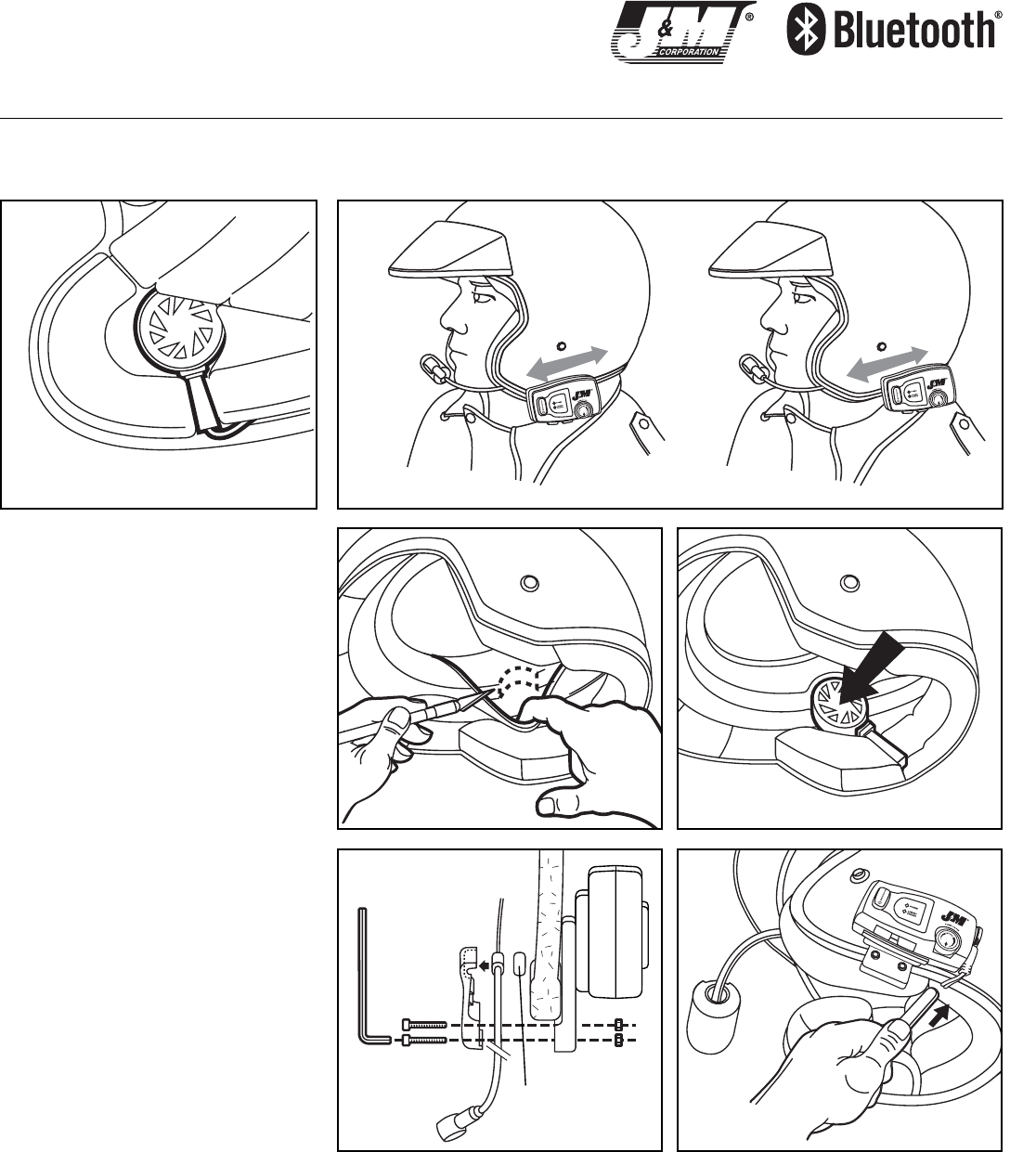
Installation into a 3/4-style Helmet
1. Begin by examining the ear pocket area in your hel-
met. Make sure that there is sufficient room to mount
the speaker in the ear pocket. If you will be mounting
the J&M DynaPort®speakers also make sure that you
can position the porting tube down along the seam in
the cheek pad. See Figure 1. (It is important to have
the helmet fit and feel the same after the speakers
are mounted as it did before the headset was
installed.) The porting tube should be positioned to
allow the sound pressure from this tube to be direct-
ed out of the ear pocket. This will help enhance bass
response.
Some three-quarter style helmets, Shoei and HJC,
for example, have ear pockets that are a bit too small
for the speaker to be properly placed. In this case fold
out the interior lining and with an Exacto®knife care-
fully remove a very thin "half moon" of polystyrene to
allow the speaker to be positioned slightly higher and
deeper into the ear pocket. See Figures 3 and 4. This
should keep the speaker from contacting your ears.
Be careful to remove only the minimum amount nec-
essary, no more than 1/4 of an inch.
Once you have made room for and/or positioned
the speakers, remove them.
2. Clean the bottom of each ear pocket with a cloth
dampened with alcohol. Peel the backing from the
supplied Velcro®pads and press them into the bottom
of each ear pocket.
3. Position the boom microphone/amplifier clamp
assembly on the left side of the helmet so that the
microphone lines up with the wearer’s mouth. Mark
this position. See Figure 2.
Tighten the clamp to the helmet with the rubber fric-
tion spacer in place.
4. Position the speakers in their proper place in the
ear pockets and press them firmly onto the Velcro®
pads.
5. Pull the large or small wind sock (which-ever you
prefer) over the microphone.
6. Using the enclosed wooden tool, carefully push the
speaker wires into the gap between the helmet liner
and shell. See Figure 6.
J&M Bluetooth Helmet Headset Installation Instructions
WARNING! Helmet speakers may not be legal in all jurisdictions. Check your local laws BEFORE using this product. J & M Corporation cannot control the circumstances surrounding the sale of this equip-
ment, the quality of installation, or the specific helmet into which this equipment is installed. Accordingly, J & M Corporation makes no warranties, expressed or implied, related thereto. A helmet with this
equipment installed may not protect the user from injury. The user assumes all liability in conjunction with accidents, injuries or losses of any kind arising out of the use of this product. Additionally, this
product should not be used in any way that would impair the user’s ability to hear traffic or other noises. Accordingly, the volume should be kept low or off, depending upon the circumstances.
6B. Installation Instructions
For 3/4 Style Helmets
1
Figure
2
Figure
3
Figure
5
Figure
6
Figure
4
Figure
Notes: When using your intercom system, regardless of headset brand or type, it is important to turn the intercom volume level
high enough for comfortable conversation, but not any higher. Unnecessarily high intercom volume levels will only increase the
unwanted wind and background noise you may experience.
Rubber Friction Spacer

Pairing the HS-BLU277 to Bluetooth Enabled Devices
(Cell Phone, Bluetooth Enabled MP3 Players, GPS Audio Command Centers, or
other Bluetooth Enabled Devices.
1. Turn on the HS-BLU277 with the on/off Intercom Volume Control (D). NOTE: If
you wish to use your HS-BLU277 unit as a driver/passenger intercom amplifier
only, it is not necessary to also turn on the Bluetooth Linking portion of this
unit.
2. To activate Bluetooth Linking Features Press and Hold the Multifunction Button
(A) for about 13 seconds, then release the Multifunction Button. The Blue
Linked /Pairing LED should now be flashing rapidly. The HS-BLU277 is now in
Pairing Mode.
3. A. If using a Bluetooth enabled cell phone, select the Hands Free menu on the
cell phone and have it search for Devices. When JM_CORP_HHS_01 is displayed
on your phone and you are asked for a passkey, Please enter: 0000. Your cell
phone is now paired with the HS-BLU277.
NOTE: If the Bluetooth portion of the headset is already on. It is necessary to
turn the Bluetooth function off by pressing and holding the multifunction
switch until the blue LED turns off and then pressing and holding the multi-
function for about 13 seconds to put it into pairing mode.
B. If using a Bluetooth Dongle. Power on the Dongle and put the Dongle in a pair-
ing mode. Turn on the HS-BLU277 and Press and Hold the Multifunction Button
(A) for about 13 seconds to put the HS-BLU277 in a pairing mode. Both the
Dongle and the HS-BLU277 LED's will be flashing rapidly until the two unit's pair
and the LED's flash at a slower rate.
C. If using a Bluetooth enabled GPS, select the tools menu and then select
Bluetooth, Turn on the HS-BLU277 and Press and Hold the Multifunction Button
(A) for about 13 seconds to put the HS-BLU277 in pairing mode, then select
connect Headset on the GPS unit. Once the HS-BLU277 is paired the display
will show JM_CORP_HHS_01.
Supported Bluetooth Profiles:
A2DP - Advanced Audio Distribution Profile.
HFP - Hands-Free Profile.
HSP - Headset Profile.
AVRCP - Audio Video Remote Control Profile.
NOTE: For Bluetooth Devices to work together with the HS-BLU277 it is impor-
tant that each device shares the same Bluetooth software profiles as the J&M
HS-BLU277.
Operation of the HS-BLU277 with a Cell Phone.
In order for the operations listed to be accomplished the HS-BLU277 must be
paired to the cell phone.
1. When receiving an incoming call the "incoming call indicator sound" will be
heard in the speakers. If the phone is set to Auto Answer the call will automati-
cally be connected to the HS-BLU277, if the phone is not set to Auto Answer the
multifunction button (A) can be depressed briefly to connect the call.
2. Use the volume Up (B) or Down (C) buttons to adjust the phone volume during
the cell phone conversation. Additional cell volume adjustments can also be
made on the cell phone itself during conversation.
3. To hang up the phone call from the HS-BLU277, depress the multifunction
button (A) briefly or wait until the party that you were speaking with to hang up.
Operation of the HS-BLU277 with a Bluetooth Enabled MP3 or
Dongle.
In order for the operation listed to be accomplished the HS-BLU277 must be paired
to the MP3 player or Dongle.
1. To set the music volume, adjust the volume of the HS-BLU277 to max volume
using the volume up (B) button. Now adjust the MP3 or music source volume
that is feeding the Dongle to a volume level in the Headset that is just before
distortion. Now adjust the volume of the HS-BLU277 to a comfortable listening
level.
Operation of the HS-BLU277 with a Bluetooth Enabled MP3
and cell phone.
1. While listening to music through the MP3 player or Dongle and the cell phone
receives an incoming call, the music will be interrupted and the "incoming call
indicator sound" will be heard in the speakers. If the phone is set to Auto
Answer the call will automatically be connected to the HS-BLU277, if the phone
is not set to Auto Answer the multifunction (A) button can be depressed briefly
to answer the call.
2. Use the volume Up or Down buttons on the cell phone itself to adjust the phone
volume during cell phone conversation.
NOTE: If the HS-BLU277 volume is adjusted during cell phone conversation. The
volume adjustments will have an effect on the music volume when the call ends
and the music resumes.
3. To hang up the phone call from the HS-BLU277, depress the multifunction (A)
button briefly or wait until the party that you were talking with to hang up.
4. The music will resume when the call has ended.
Operation of the Intercom
1. Using the appropriate lower section hookup cord HC-ZBT or PBT connect a stan-
dard J&M Dualmode Headset to jack (E) on the HS-BLU277.
2. Rotate the intercom volume control knob (D) to a volume level position for com-
fortable conversation, but not any higher. Unnecessarily high intercom volume
levels will only increase the unwanted wind and back ground noise you may
experience.
NOTE: It is not necessary for the Bluetooth part of the HS-BLU277 to be turned
on for the intercom portion of this system to function.
POWER
LINKED/
PAIRING
P
O
W
E
R
O
N
/
O
F
F
MULTIFUNCTION
I
N
T
V
O
L
A
B
CD
E
NOTE: Before using the HS-BLU277, its
internal lithium/polymer power cell
should be charged for at least 6 hours.
Thank you for the confidence you have shown by purchasing one
of J&M’s innovative products. If you have any questions during the
installation, or require further assistance, you may call us at
1-800-358-0881 from 8:00 a.m. to 5:00 p.m. Mountain Standard
Time, Monday through Friday.
Tucson, Arizona U.S.A.
Tel (800) 358-0881
Website: http://www.jmcorp.com
E-mail: audio@jmcorp.com
7. Operation Instructions