JADAK a business unit of Novanta 010A0001 RFID PORTAL READER User Manual SR100 User Guide
SkyeTek, Inc RFID PORTAL READER SR100 User Guide
User Guide

SR100 USER GUIDE
VERSION 1.0

SR100 User Guide Page | 2
CONTACT INFORMATION
SKYETEK, INC.
1525 Market St. Suite 200
Denver, CO 80202
http://www.skyetek.com
SALES:
sales@skyetek.com
TECHNICAL SUPPORT:
techsupport@skyetek.com
http://support.skyetek.com

SR100 User Guide Page | 3
TABLE OF CONTENTS
SR100 User Guide ............................................................................................ 1
Contact Information ......................................................................................... 2
Table of Contents ............................................................................................ 3
Chapter 1 ...................................................................................................... 6
SR100 Overview ........................................................................................... 6
Features.................................................................................................. 6
SkyeReader Console .................................................................................... 6
FCC Notice ............................................................................................... 6
Note Regarding RF Exposure .......................................................................... 6
Chapter 2 ...................................................................................................... 8
Mechanical Specifications ............................................................................... 8
Chapter 3 ...................................................................................................... 9
Environment Specifications .............................................................................. 9
General Ratings and Operating Conditions ......................................................... 9
Chapter 4 ..................................................................................................... 10
Electrical Specifications ................................................................................ 10
Absolute Maximum Ratings .......................................................................... 10
Chapter 5 ..................................................................................................... 11
Radio Specifications and Regional Compliance ...................................................... 11
RF Radio Power ........................................................................................ 11
Frequency Range ...................................................................................... 11
Tag Protocols ........................................................................................... 11
Regional Regulations .................................................................................. 11
Radio Specifications................................................................................... 11
Chapter 6 ..................................................................................................... 13
Host Interface Specification ............................................................................ 13

SR100 User Guide Page | 4
USB ...................................................................................................... 13
TCP/IP ................................................................................................... 13
Discovery ........................................................................................................ 13
Opening a socket ............................................................................................... 14
Chapter 7 ..................................................................................................... 15
Antenna Options .......................................................................................... 15
Internal Antenna ....................................................................................... 15
External Antenna ...................................................................................... 15
Chapter 8 ..................................................................................................... 16
Software Specifications ................................................................................. 16
Host Communication – SkyeTek Protocol v3 ...................................................... 16
SkyeReader Console Software ....................................................................... 17
Chapter 9 ..................................................................................................... 18
System Parameters ...................................................................................... 18
Changing System Paramters ......................................................................... 18
System Parameter Descriptions ..................................................................... 18
Serial Number .................................................................................................. 19
Firmware Version .............................................................................................. 19
Hardware Version .............................................................................................. 19
Product Code ................................................................................................... 19
Reader ID ........................................................................................................ 20
Reader Name ................................................................................................... 20
User Port Direction ............................................................................................ 20
User Port Value ................................................................................................. 20
MUX Control ..................................................................................................... 21
Operating Mode ................................................................................................ 21
Command Retry ................................................................................................ 21
Power Level ..................................................................................................... 22
Current Frequency ............................................................................................. 22

SR100 User Guide Page | 5
Start Frequency ................................................................................................ 23
Stop Frequency ................................................................................................. 23
Hop Channel Spacing .......................................................................................... 23
Frequency Hopping Sequence ................................................................................ 24
Modulation Depth .............................................................................................. 24

SR100 User Guide Page | 6
CHAPTER 1
SR100 OVERVIEW
The SR100 is RFID portal reader with an integrated antenna designed for use in North America and
Europe. The SR100 can read and write to ISO 18000-6C (EPC Class 1 Gen 2) transponders with a
maximum output power of 1W.
FEATURES
• Common communications protocol – All SkyeTek products use SkyeTek Protocol v3 (STPv3) to
drive low level communication. SkyeTek’s C and C# APIs are built on top of this protocol to give
users methods for all reader and tag operations to use from custom software applications.
• The SR100 has an internal 5dBi Circular Polarized antenna as well as a 50Ohm output to
connect and external antenna.
• Communicate via USB or TCP over Ethernet. Send STPv3 commands to the reader using these
two interfaces allow easy integration into most modern systems. Users can access all reader
functions over both interfaces, including firmware upgrades, security features and all tag
commands.
SKYEREADER CONSOLE
The SR100 ships with the SkyeReader Console software package. This software runs on Windows XP,
Vista, and 7. SkyeReader Console includes the following features:
FCC NOTICE
This equipment complies with Part 15 of the FCC rules. Any changes or modifications not expressly
approved by the manufacturer could void the user's authority to operate the equipment.
This device complies with Part 15 of the FCC rules subject to the following two conditions:
1. This device may not cause harmful interference
2. This device must accept all interference received, including interference that may cause
undesired operation.
NOTE REGARDING RF EXPOSURE
This equipment complies with FCC radiation exposure limits set forth for an uncontrolled environment.
This equipment should be installed and operated with minimum distance 25cm between the radiator
and your body. This transmitter must not be co-located or operating in conjunction with any other
antenna or transmitter.

SR100 User Guide Page | 7

SR100 User Guide Page | 8
CHAPTER 2
MECHANICAL SPECIFICATIONS
(Insert Drawings)

SR100 User Guide Page | 9
CHAPTER 3
ENVIRONMENT SPECIFICATIONS
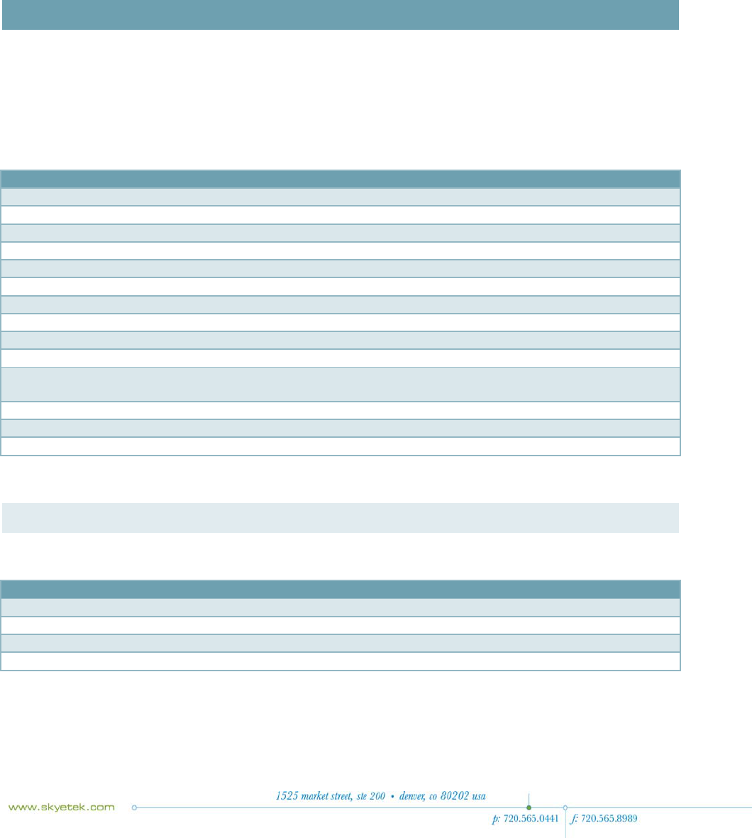
GENERAL RATINGS AND OPERATING CONDITIONS
Specification Rating
Temperature Range
Operating
Storage
Humidity
Operating, continuous storage
Transient storage (<24 hours)
ESP Protection
SR100 User Guide Page | 10
CHAPTER 4
ELECTRICAL SPECIFICATIONS
This chapter discusses the electrical specifications of the SR100. Unless otherwise noted, the following
assumptions apply to these specifications:
• Operating Temperature is 25° C.
• Frequency is 915MHz
• Supply voltage is 6V or 48V if using Power over Ethernet.
Specification Min
Typical
Max
Units
Logic Inputs
High State 2
V
Low State
0.8
V
Input Current 4
25
m
A
Logic Outputs
Output High 2.9 3.3
V
Output Low 0
0.4
V
Output Current 4
25
m
A
Power Supplies
DC Power Supply 5.0 6.0
6.5
V
Power over
Ethernet 48 48
52
V
Peak Transmit Current Consumption
ABSOLUTE MAXIMUM RATINGS
Specification Rating
Maximum Input Voltage, DC Jac
k
9
V
Maximum Voltage, PoE 52
V
Digital I/O Voltage 3.3
V
Antenna VSW
R
1.5:1 or better

SR100 User Guide Page | 11
CHAPTER 5
RADIO SPECIFICATIONS AND REGIONAL COMPLIANCE
RF RADIO POWER
The output power of the SR100 is adjustable from 10-30dBm in steps of 0.1dBm with +/- 1dB accuracy.
With this adjustable power, the user can configure the device to suit their needs of reading
transponders at different ranges, or to reduce overall power consumption. See “Power Level” on page
22 for information on how to set the RF output power.
FREQUENCY RANGE
The SR100 is a multi-frequency device that can operate anywhere in the 860-960MHz range, which
covers the world’s major UHF RFID bands. The user can set a Start and Stop frequency so the reader
may operate in a subset of this band. See “System Parameters” below for more information on
adjusting the Current, Start and Stop frequency for the reader.
SkyeTek will lock all pertinent system parameters for a given region (frequency, hope channel spacing,
etc.) when the unit is sold in said region. This is to prevent the user from violated regional
regulations.
TAG PROTOCOLS
The SR100 supports basic tag commands (identify, read and write) for the following tag protocols:
• EPC C1G2 (ISO 18000-6C)
• iPX EM
NOTE - For additional tag support information, see the Tag Support list included with the
documentation for your SR100.
REGIONAL REGULATIONS
The SR100 has been tested and approved for regional compliance in the following regions.
Region Agency Approvals
Publications/Regulations
North America FCC Part 15
Europe ETSI
RADIO SPECIFICATIONS
For the table below, assume an operating temperature of 25°C.

SR100 User Guide Page | 12
Specification Min
Typical
Max
Units
RF Characteristics
Frequency ranges
(Direct Output) 860
960
MHz
Hop Channel
Spacing 100
200
300
KHz
Transmission Parameters
Transmit Power 10
30
dBm
Optimum PA Load
Impedance 50
Ohms
Receiver
Parameters
Sensitivity at 50
kbps (30dBM
output power)
60
dB
Sensitivity at 80
kbps (30dBm
output power)
60
dB

SR100 User Guide Page | 13
CHAPTER 6
HOST INTERFACE SPECIFICATION
This chapter describes the host interface connections of the SR100.
The SR100 supports two host interfaces:
• USB
• TCP/IP over Ethernet
Each interface is active when the user makes the connection with either an Ethernet cable or a USB
cable. If both cables are connected, USB has priority and the Ethernet connection will not be able to
communicate with the reader. The SR100 receives and transmits STPv3 commands over both interfaces.
USB
The SR100 supports a USB Full Speed connection. It uses a USB to serial converter internally to
communicate with the reader which requires a driver to be installed on your host computer. This driver
is included with the software CD, is installed automatically with the SkyeReader Console software, or
can be downloaded from www.ftdichip.com/Drivers/VCP.htm.
TCP/IP
The SR100 can use TCP sockets for communication as well. The C# API provides methods for device
discovery and communication, but if you want to use a different programming environment, the
information below describes how these methods work.
DISCOVERY
The SR100 utilizes the .NET Micro Framework for network communication. This is very nice because a
discovery function is built into the device. All that is required is to send the string “DOTNETMF” over a
UDP Multicast on your network. The device will receive this string and send out a UDP Multicast that
looks like this:
You can use the MAC Address and IP Address from this response to create a socket connection as
described below. You can match the MAC Address from this response to the one printed on the label on
the bottom of your SR100.

SR100 User Guide Page | 14
The SR100 uses DHCP to dynamically obtain an IP address. When you first apply power to the unit and
then a network connection, it will take a few seconds for this process to complete. You can watch the
LEDs on the Ethernet connector for an indicator; when the Green LED starts blinking, the device is
communicating with the network and you may try the discovery process.
OPENING A SOCKET
After you have discovered your device’s IP Address, you can now open a TCP socket to your SR100. The
SR100 is always listening for a new connection if it is not already connected. You must use the
following parameters:
• Two way communication socket (stream)
• Use Port 2000
After the socket connection is established, you may stream data across this socket freely. The SR100
will receive and transmit STPv3 commands and responses. To close the socket, simply terminate the
connection, and the SR100 will recognize the connection has been closed and listen for a new one.

SR100 User Guide Page | 15
CHAPTER 7
ANTENNA OPTIONS
The SR100 supports two antenna options: internal antenna and external antenna. The default is to use
the internal antenna because it is always connected.
To change the active antenna, the user sends a Write System Parameter command to the reader with
the following attributes:
Command Address Blocks
Data
Write System Paramete
r
0x0060 0001
0x01 for external
0x02 for internal (Default)
You can also issue a Store Default System Parameter with the same attributes to keep your settings
after a power cycle.
INTERNAL ANTENNA
The internal antenna is a 5dBi gain Circularly Polarized patch antenna. This high performance antenna
will allow the user to read tags up to 5m from the reader in free space. Because it is circularly
polarized, tag orientation does not play a major factor in read distance.
EXTERNAL ANTENNA
The SR100 can use any external antenna with a 50Ω load. Keep the following items in mind when
selecting an external antenna:
• Antenna Gain – The SR100 has 1W of output power, and the maximum EIRP allowed by the FCC
is 4W. The highest gain antenna that can be used with the SR100 in North America is 5.35dBi.
Check regional regulations for other restrictions.
o Antenna gain is also directly related to beam width. The higher the gain, the more
directional the antenna is, and the narrower the beam width.
• Cable – Different cables have different losses over distance. For example, standard RG58
coaxial cable losses approximately 0.49dB/meter. Over longer distances, this can cause
significant loss of power.
• Polarization – A linearly polarized antenna will be very sensitive to tag orientation, where a
circularly polarized antenna will not be as sensitive.
SR100 User Guide Page | 16
CHAPTER 8
SOFTWARE SPECIFICATIONS
HOST COMMUNICATION – SKYETEK PROTOCOL V3
The SR100 uses SkyeTek Protocol v3 for all communication. For more information about this protocol,
including commands, flags, request and response formats, please see the SkyeTek Protocol v3
Reference Guide.
The basic command and response format is illustrated below.
Request Format (bytes) ASCII Mode
Flags Cmd. RID Tag
Type TID
Length TID AFI
Addr.
# of
Blocks Data
Length Data
CRC
4 4 8 4 4 32
(max)
2 4 4 4 2K 4
Request Format (bytes) Binary Mode
Mes.
Length Flags Cmd.
RID Tag
Type TID
Len. TID AFI
Addr
# of
Blks. Data
Len. Data
CRC
2 2 2 4 2 1 16
(max)
1 2 2 2 1K 2
Response Format (bytes) ASCII Mode
Response Code RID Tag Type Data Length
Response Data
CRC
4 8 4 4 2K 4
Response Format (bytes) Binary Mode
Message Length Response Code RID Tag Type
Data Length
Response Data CRC
2 2 4 2 2 1K 2
Shading Information
Required Fields

SR100 User Guide Page | 17
Optional Fields (depending on the command and flags)
Required Fields, depending on the command
SKYEREADER CONSOLE SOFTWARE
Information to follow.

SR100 User Guide Page | 18
CHAPTER 9
SYSTEM PARAMETERS
System parameters let you configure reader settings to customize them for your environment. You can
temporarily alter parameters in memory or change the default values that are stored on the SR100 non-
volatile memory. The following table summarizes the parameters for the SR100.
Paramete
r
Address
Length (bytes)
Default Value
Serial Number 0x0000
0x0004
0x00000000
Firmware Version 0x0001
0x0004
0xXXXXXXXX (depends on release)
Hardware Version 0x0002
0x0004
0xXXXXXXXX (depends on release)
Product Code 0x0003
0x0002
0x000
A
Reader ID 0x0004
0x0004
0xFFFFFFFF
Reader Name 0x0005
0x0020
SR100 (in hexadecimal)
User Port Direction 0x0008
0x0001
0x00
User Port Value 0x0009
0x0001
0x00
MUX Control 0x000
A
0x0001
0x00
Operating Mode 0x000C
0x0001
0x00
Command Retry 0x0011
0x0001
0x05
Power Level 0x0012
0x0001
0xF
A
Current Frequency 0x0030
0x0004
0x3689CAC0 (915 MHz)
Start Frequency 0x0031
0x0004
0x35C80160 (902.3 MHz)
Stop Frequency 0x0032
0x004
0x374B9420 (927.7 MHz)
Hop Channel Spacing 0x0034
0x0004
0x00030D40
Frequency Hopping Sequence 0x0035
0x0001
0x01 (random)
Modulation Depth 0x0036
0x0001
0x64 (100%)
CHANGING SYSTEM PARAMTERS
You can read or write system parameters via the following commands:
• Read System Parameter—reads the current value of the system parameter at the memory
address specified.
• Write System Parameter—writes a new value to the system parameter at the memory address
specified.
• Store Default System Parameter—writes a new system parameter value to the EEPROM.
• Retrieve Default System Parameter—reads the system parameter value at the address specified
out of EEPROM.
See the SkyeTek Protocol v3 Reference Guide for a complete list of commands.
SYSTEM PARAMETER DESCRIPTIONS

SR100 User Guide Page | 19
This section describes each SR100 system parameter.
SERIAL NUMBER
• Returns the serial number of the reader
• Parameter address: 0x0000
• Length (bytes): 1
• Default value: 0x00000000
• Read-only
FIRMWARE VERSION
Returns the firmware version currently loaded on the reader. (Refer to the SkyeModule M10 Release
Notes for more information about the specific firmware release.)
• Refer to the SkyeTek Development Kit User Guide for information about updating firmware.
• Parameter address: 0x0001
• Length (bytes): 4
• Default value: 0xXXXXXXXX (depending on release)
• The firmware version uses this format:
a) Product type (1 Byte)
b) Major revision (1 Byte)
c) Minor revision/build number (2 bytes)
• Read-only
HARDWARE VERSION
• Returns the current hardware version of the reader
• Parameter address: 0x0002
• Length (bytes): 4
• Default value: 0xXXXXXXXX (depending on release)
• The hardware version uses the following format:
a) Product type (1 Byte)
b) Major revision (1 Byte)
c) Minor revision/build number (2 Bytes)
• Read-only
PRODUCT CODE
• Returns the SkyeTek product code identifier. (Each SkyeTek product has a unique product
code.)
• Parameter address: 0x0003
• Length (bytes): 2
• Default value: 0x000A
• Read-only

SR100 User Guide Page | 20
READER ID
• Specifies the Reader ID, which is a reader-specific identifier. It lets the reader execute and
respond only to those commands intended for it. The reader determines if the Reader ID in the
request matches its internal Reader ID. If the ID does not match, the reader does not respond.
• Parameter address: 0x0004
• Length (bytes): 4
• Default value: 0xFFFFFFFF (depending on release)
• Select the Reader ID functionality by specifying the RID Flag in the request. This setting lets
you use multiple readers on the same bus or networked together.
• Read/write
Note -Changing the reader ID from the factory default of FFFFFFFF to any other value disables Loop
Mode, which is used for read range demonstrations. See ‘‘Selecting Any Supported Tag
Continuously (Loop Mode)’’ for an example of using Loop Mode.
READER NAME
• Identifies a reader with a 32-byte user-defined name.
• Parameter address: 0x0005
• Length (bytes): 32
• Default value: SkyeModule M10 (in hex)
• Read/write
USER PORT DIRECTION
• Sets the direction of the GPIO pins of the reader.
• Parameter address: 0x0008
• Length (bytes): 1
• Default value: 0x00
• A one in the bit position indicates that the corresponding GPIO pin is an input.
• A zero in the bit position indicates that the corresponding GPIO pin is an output.
• Read/write
• Bits correspond to the pins as follows:
o BIT0 – GPIO0
o BIT1 – GPIO1
o BIT2 – GPIO2
o BIT3 – GPIO3
o BIT4 – reserved for future use
o BIT5 – reserved for future use
o BIT6 – reserved for future use
o BIT7 – reserved for future use
USER PORT VALUE
• Sets the value of the GPIO pins of the reader.
SR100 User Guide Page | 21
• Parameter address: 0x0009
• Length (bytes): 1
• Default value: 0x00
• A one in the bit position indicates that the corresponding GPIO pin is a logic high.
• A zero in the bit position indicates that the corresponding GPIO pin is logic low.
• The enable bit (bit 7) must be set for the settings to take effect.
• Bits correspond to the pins as follows:
o BIT0 – GPIO0
o BIT1 – GPIO1
o BIT2 – GPIO2
o BIT3 – GPIO3
o BIT4 – reserved for future use
o BIT5 – reserved for future use
o BIT6 – reserved for future use
o BIT7 – enable
• Read/write
MUX CONTROL
• Controls a SkyePlus multiplexer. See the SkyePlus Multiplexer Reference Guide for complete
information about using this parameter.
• Parameter address: 0x000A
• Length (bytes): 1
• Default value: 0x00
• Read/write
OPERATING MODE
• Puts the reader into sleep mode.
• Parameter address: 0x000C
• Length (bytes): 1
• Default value: 0x00
• Writing a value 0x01 to this parameter puts the reader into sleep mode.
• Sending any command on any interface wakes the reader from sleep mode.
• Read/write
COMMAND RETRY
• One-byte value.
• Parameter address: 0x0011
• Length (bytes): 1
• Default value: 0x05
• Can be set by the host.
• Specifies the number of times a tag command is executed internally in the reader before
responding with a failure response.
• Applies only to tag-specific SkyeTek Protocol commands.
SR100 User Guide Page | 22
• Valid range of values is 0-255 (0x00–0xFF).
• The command is repeated internally “n” number of times, where n is the value specified by the
host, unless there is a successful response. When a successful response occurs, the reader stops
repeating the command and sends a success response back to the host.
• Read/write
Note - Increasing the value of this parameter increases the time that the reader takes before it
sends a failure message if a failure occurs. To avoid unnecessary delays, be sure to determine the
optimal number of retries for your particular use.
POWER LEVEL
• Configures the power level for the reader.
• Parameter address: 0x0012
• Length (bytes): 1
• Default value: 0xFA (30 dBm)
• Power level is set in steps of 0.1 dB from 10 dBm to 30 dBm.
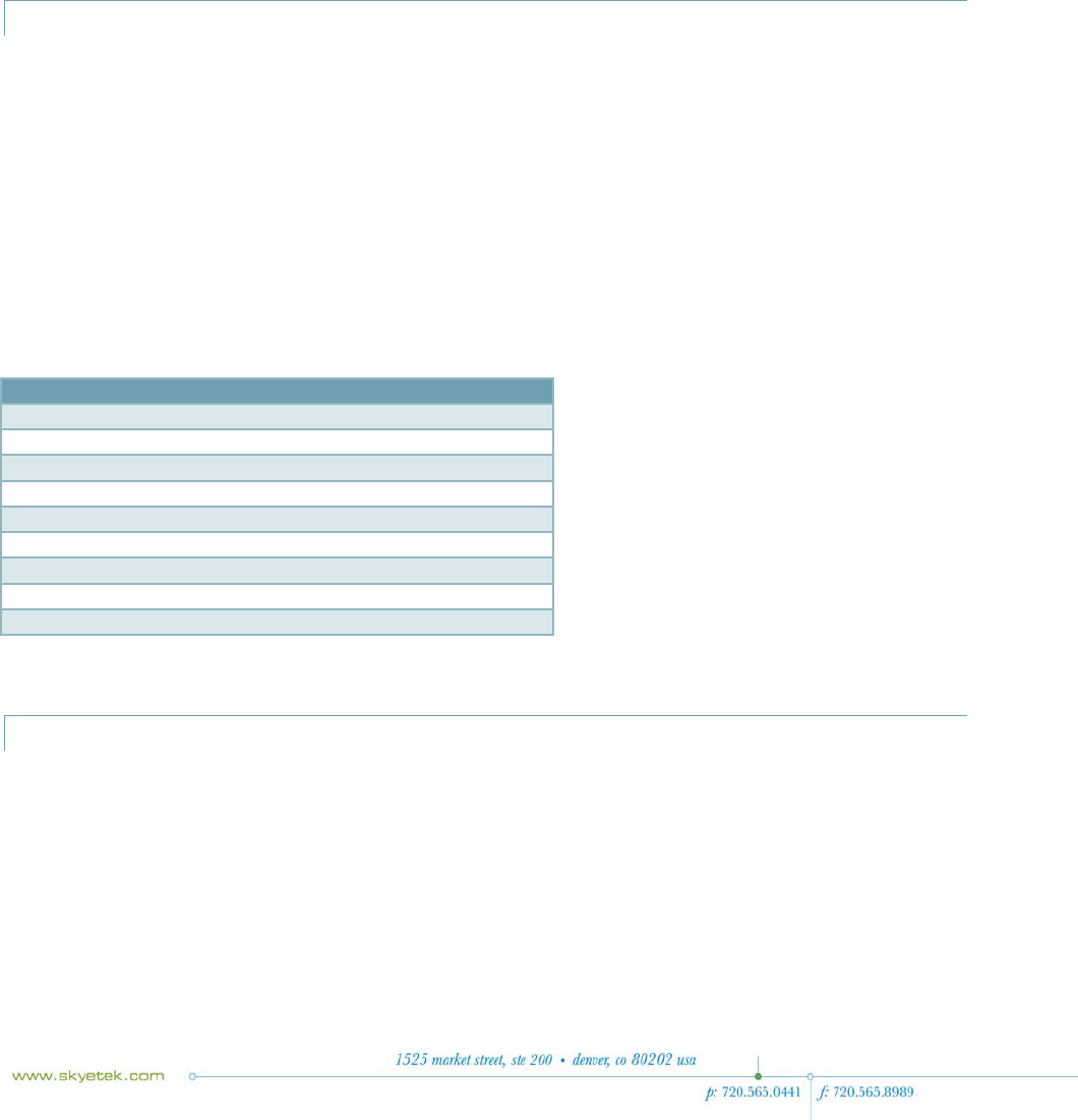
• Power levels are written in hex corresponding to a decimal value between 50 and 250 (see
Table 9-10).
• Use the following equation to calculate the value to be written for a desired power level:
(Desired power in dBm - 5)/0.1 = decimal value to write to system parameter
Common Power Levels
Power (dBm) SkyeTek Decimal Value
Hex Equivalent
10 50 0x32
12 70 0x46
15 100 0x64
17 120 0x78
20 150 0x96
21 160 0xA0
24 190 0xBE
27 220 0xDC
30 250 0xF
A
• Read/write
CURRENT FREQUENCY
• Sets the current frequency with which the reader singulates a tag.
• Parameter address: 0x0030
• Length (bytes): 4
• Default value: 0x3689CAC0 (915 MHz)
• This parameter is a 4-byte hex equivalent of the frequency. Table 9-11 shows hex values for
commonly used frequencies.
• Read/write

SR100 User Guide Page | 23
START FREQUENCY
• Sets the low end of the frequency range under which the reader operates.
• Parameter address: 0x0031
• Length (bytes): 4
• Default value: 0x35C80160 (902.3 MHz)
• This parameter is written with a 4-byte hex equivalent of the frequency desired. See Table 9-
11 for commonly used frequencies and their hex values.
• To enable frequency hopping, set a frequency range using the Start Frequency and Stop
Frequency system parameters. Then use the Frequency Hopping Sequence parameter to set the
frequency hopping mode (either sequential or pseudo-random). To disable frequency hopping,
set the Start Frequency and Stop Frequency parameter to the same value.
• Read/write
STOP FREQUENCY
• Sets the high end of the frequency range under which the reader operates.
• Parameter address: 0x0032
• Length (bytes): 4
• Default value: 0x374B9420 (927.7 MHz)
• This parameter is written with a 4-byte hex equivalent of the frequency desired. See Table 9-
11 for commonly used frequencies and their hex values.
• To enable frequency hopping, set a frequency range using the Start Frequency and Stop
Frequency system parameters. Then use the Frequency Hopping Sequence parameter to set the
frequency hopping mode (either sequential or pseudo-random). To disable frequency hopping,
set the Start Frequency and Stop Frequency parameter to the same value.
• Read/write
Commonly Used Frequencies
Frequency (MHz) Hex Equivalent Description
865.7 0x339988A0 ETSI Start
866.7 0x33A8CAE0 ETSI Center
867.9 0x33BB1A60 ETSI Stop
902.3 0x35C80160 FCC Start
915.0 0x3689CAC0 FCC Cente
r
927.7 0x374B9420 FCC Stop
HOP CHANNEL SPACING
• Controls the hop channel spacing when frequency hopping is enabled.
• Parameter address: 0x0034
• Length (bytes): 4
• Default value: 0x00030D40 (200 KHz)
• To enable frequency hopping, set a frequency range using the Start Frequency and Stop
Frequency system parameters. Then use the Frequency Hopping Sequence parameter to set the
SR100 User Guide Page | 24
frequency hopping mode (either sequential or pseudo-random). To disable frequency hopping,
set the Start Frequency and Stop Frequency parameter to the same value.
• Read/write
FREQUENCY HOPPING SEQUENCE
• Switches the hopping sequence between pseudo-random and sequential mode.
• Parameter address: 0x0035
• Length (bytes): 1
• Default value: 0x01 (pseudo-random)
• To set the reader to sequential hopping mode, write 0x00 to this parameter.
• To reset the reader to pseudo-random hopping sequence, write 0x01 to this parameter.
• To enable frequency hopping, set a frequency range using the Start Frequency and Stop
Frequency system parameters. Then use the Frequency Hopping Sequence parameter to set the
frequency hopping mode (either sequential or pseudo-random). To disable frequency hopping,
set the Start Frequency and Stop Frequency parameter to the same value.
• Read/write
MODULATION DEPTH
• Sets the modulation depth of the reader-to-tag transmissions, as calculated by the equation:
(Vmax - Vmin)/Vmax.
• Parameter address: 0x0036
• Length (bytes): 1
• Default value: 100%
• The values for the modulation depths are in steps of 10, ranging from 10% to 100%.
• The values are the hex equivalent of the corresponding modulation depth.
Common Modulation Depth Values
Modulation Depth (%) Hex Equivalent
30 0x1E
80 0x50
90 0x5
A
100 0x64
• The modulation depth is calculated by the reader using the equation:
o (VMAX - VMIN)/VMAX where VMAX is the RF voltage when transmit power is maximum and
VMIN is the RF voltage when transmit power is minimum. (For 100% modulation depth,
VMIN equals zero.)
• See the manufacturer’s tag data sheet for the modulation depth supported for the tags in your
application.
• Read/write