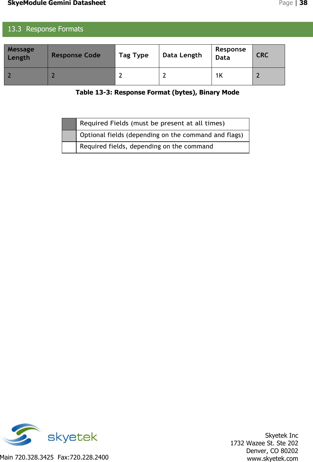
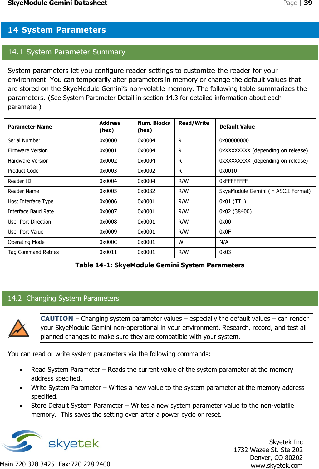
JADAK a business unit of Novanta GEMINI003 SkyeModule Gemini User Manual

SkyeTek, Inc SkyeModule Gemini

User Manual

       SKYEMODULE GEMINI DATASHEET VERSION 051214
SkyeModule Gemini Datasheet   Page | 2    Skyetek Inc 1732 Wazee St. Ste 202 Denver, CO 80202 www.skyetek.com Main 720.328.3425  Fax:720.228.2400  COPYRIGHT INFORMATION: Copyright 2014 SkyeTek, Inc., 1732 Wazee St. Suite 202, Denver, Colorado 80202, U.S.A. All rights reserved. Version 051214 This product or document is protected by copyright and distributed under licenses restricting its use, copying, distribution, and decompilation. No part of this product or document may be reproduced in any form by any means without prior  written authorization of SkyeTek and its licensors, if any. SkyeTek and SkyeWare are trademarks or registered trademarks of SkyeTek, Inc. MIFARE and NXP is a registered trademark of Royal Philips Electronics. MicroSoft and Windows are registered trademarks of Microsoft Corporation. TECHNICAL SUPPORT AND CONTACT INFORMATION SkyeTek, Inc. 1732 Wazee St. Suite 202 Denver, CO 80202 http://www.skyetek.com SALES: sales@skyetek.com TECHNICAL SUPPORT: support@skyetek.com
SkyeModule Gemini Datasheet   Page | 3    Skyetek Inc 1732 Wazee St. Ste 202 Denver, CO 80202 www.skyetek.com Main 720.328.3425  Fax:720.228.2400  TABLE OF CONTENTS 1 INTRODUCTION .............................................................................................................................................. 7 1.1 GETTING STARTED .............................................................................................................................................. 7 1.2 WHY A SKYETEK MODULE? .................................................................................................................................. 7 1.3 ADDITIONAL READING ......................................................................................................................................... 8 1.4 REVISION HISTORY .............................................................................................................................................. 9 2 DEFINITION OF TERMS ................................................................................................................................. 10 3 ORDERING INFORMATION ........................................................................................................................... 11 3.1 GEMINI STANDARD PART NUMBERS ..................................................................................................................... 11 3.2 PART NUMBER DETAILS ..................................................................................................................................... 11 3.3 HOW TO BUY ................................................................................................................................................... 12 4 SKYEMODULE GEMINI OVERVIEW ................................................................................................................ 13 4.1 DESCRIPTION.................................................................................................................................................. 13 4.2 BLOCK DIAGRAM .............................................................................................................................................. 13 4.3 FEATURES ........................................................................................................................................................ 14 4.4 APPLICATIONS .................................................................................................................................................. 14 4.5 AGENCY APPROVALS ......................................................................................................................................... 14 5 MECHANICAL SPECIFICATIONS ..................................................................................................................... 15 6 PINNING INFORMATION .............................................................................................................................. 16 6.1 CONNECTOR DESCRIPTIONS ................................................................................................................................ 16 6.2 HOST INTERFACE CONNECTOR PIN MAPPING ......................................................................................................... 17 6.3 EXTERNAL ANTENNA CONNECTOR PIN MAPPING .................................................................................................... 18 6.4 USING THE GPIO PINS ...................................................................................................................................... 19 7 ENVIRONMENTAL SPECIFICATIONS .............................................................................................................. 20 7.1 ELECTROSTATIC PRECAUTIONS ............................................................................................................................. 20 7.2 GENERAL RATINGS AND OPERATING CONDITIONS ................................................................................................... 20 8 ELECTRICAL SPECIFICATIONS ........................................................................................................................ 21 8.1 ELECTRICAL CHARACTERISTICS ............................................................................................................................. 21 8.2 ABSOLUTE MAXIMUM RATINGS ........................................................................................................................... 22 9 PERFORMANCE SPECIFICATIONS .................................................................................................................. 23 9.1 TIMING SPECIFICATIONS ..................................................................................................................................... 23 9.2 RANGE SPECIFICATIONS...................................................................................................................................... 24 10 RADIO SPECIFICATIONS ............................................................................................................................ 25 10.1 AGENCY APPROVALS ......................................................................................................................................... 25 10.2 HOST DEVICE LABELING FOR FCC ........................................................................................................................ 25
SkyeModule Gemini Datasheet   Page | 4    Skyetek Inc 1732 Wazee St. Ste 202 Denver, CO 80202 www.skyetek.com Main 720.328.3425  Fax:720.228.2400  10.3 FREQUENCY BAND ............................................................................................................................................ 25 10.4 TAG PROTOCOLS .............................................................................................................................................. 25 11 HOST INTERFACE SPECIFICATIONS ............................................................................................................ 26 11.1 USB 2.0 ......................................................................................................................................................... 27 11.2 TTL SERIAL ...................................................................................................................................................... 28 11.3 SPI ................................................................................................................................................................ 30 11.4 I2C ................................................................................................................................................................. 33 12 SKYEMODULE GEMINI ANTENNA OPTIONS .............................................................................................. 36 13 COMMUNICATING WITH THE MODULE .................................................................................................... 37 13.1 HOST COMMUNICATION (SKYETEK PROTOCOL V3).................................................................................................. 37 13.2 REQUEST FORMATS ........................................................................................................................................... 37 13.3 RESPONSE FORMATS ......................................................................................................................................... 38 14 SYSTEM PARAMETERS .............................................................................................................................. 39 14.1 SYSTEM PARAMETER SUMMARY .................................................................................................................. 39 14.2 CHANGING SYSTEM PARAMETERS ........................................................................................................................ 39 14.3 SYSTEM PARAMETER DETAILS.............................................................................................................................. 40 15 SPECIAL FEATURES .................................................................................................................................. 44 15.1 SLEEP MODES .................................................................................................................................................. 44 15.2 FEATURE REQUESTS .......................................................................................................................................... 44
SkyeModule Gemini Datasheet   Page | 5    Skyetek Inc 1732 Wazee St. Ste 202 Denver, CO 80202 www.skyetek.com Main 720.328.3425  Fax:720.228.2400  LIST OF FIGURES Figure 3-1: SkyeTek Part Number Format ........................................................................................... 11 Figure 4-1: SM-GM-AC (with all connectors) ....................................................................................... 13 Figure 4-2: SkyeModule Gemini Block Diagram ................................................................................... 13 Figure 5-1: SM-GM Mechanical Drawing ............................................................................................. 15 Figure 6-1: Host Interface Connector Pin Numbering ........................................................................... 17 Figure 6-2: External Antenna Pin Numbering ...................................................................................... 18 Figure 9-1: Tag Command Execution Time Measurement .................................................................... 23 Figure 9-2: Range Specifications ........................................................................................................ 24 Figure 11-1: USB Connection Diagram ................................................................................................ 27 Figure 11-2: TTL Serial Connection Diagram ....................................................................................... 28 Figure 11-3: TTL Serial Timing Diagram ............................................................................................. 29 Figure 11-4: SPI Connection Diagram ................................................................................................. 30 Figure 11-5: SPI Request Setup and Sample Timing ............................................................................ 31 Figure 11-6: SPI Request Timing........................................................................................................ 31 Figure 11-7: SPI Response Timing ..................................................................................................... 32 Figure 11-8: I2C Connection Diagram ................................................................................................. 33 Figure 11-9: I2C Timing Diagram ........................................................................................................ 35
SkyeModule Gemini Datasheet   Page | 6    Skyetek Inc 1732 Wazee St. Ste 202 Denver, CO 80202 www.skyetek.com Main 720.328.3425  Fax:720.228.2400  LIST OF TABLES Table 1-1: Revision History .................................................................................................................. 9 Table 3-1: Gemini Standard Part Numbers .......................................................................................... 11 Table 3-2: Part Number Details .......................................................................................................... 11 Table 6-1: SkyeModule Gemini Connector Specification ....................................................................... 16 Table 6-2: SkyeModule Gemini Pin Descriptions .................................................................................. 17 Table 6-3: External Antenna Pin Descriptions ...................................................................................... 18 Table 7-1: Environmental Ratings/Operating Conditions ...................................................................... 20 Table 8-1: SkyeModule Gemini Electrical Specifications ........................................................................ 21 Table 8-2: Absolute Maximum Ratings ................................................................................................ 22 Table 9-1: Timing Specifications ........................................................................................................ 23 Table 13-1: Request Format (bytes), ASCII Mode ............................................................................... 37 Table 13-2: Request Format (bytes), Binary Mode .............................................................................. 37 Table 13-3: Response Format (bytes), Binary Mode ............................................................................ 38 Table 14-1: SkyeModule Gemini System Parameters ........................................................................... 39
SkyeModule Gemini Datasheet   Page | 7    Skyetek Inc 1732 Wazee St. Ste 202 Denver, CO 80202 www.skyetek.com Main 720.328.3425  Fax:720.228.2400  1 Introduction 1.1 Getting Started Operating your SkyeModule Gemini begins with finding a method to connect to a host.  The SkyeModule itself does not operate without direction (commands) from a host.  The host can be in the form of a PC or, more typically, an embedded microcontroller.  This document explains the physical and electrical characteristics of the module, so you can understand how to integrate the Gemini into a finished product. For initial demonstration of the module, SkyeWare v4 software is available on the media that came with the developer/evaluation kit or available for download at support.skyetek.com.  Open this software on your windows PC and it will be recognized when you connect through USB or RS232 (with developer kit interface board).  The software demonstrates features like selecting tags, reading and writing.  It also has a powerful command builder that lets you format, send and receive any command to and from the reader.  More about SkyeWare can be found in the SkyeWare User Guide.  See the Additional Reading section below. The next step after demonstrating the module’s functionality is developing your own communication with the module.  This can be achieved with simple code on a microcontroller or using the SkyeTek API on a PC.  Once connected to a host through one of the four host interfaces, the reader to host communication is formatted with a full featured protocol called SkyeTek Protovol v3.  In order to make learning commands and formatting easy, we have developed a series of application notes with examples to get you started.  The application notes start with basic tag and reader commands and become very detailed for tags with special features.  Read more about the protocol and commands in section 13, Communicating with the Module and then move on to the Additional Reading in section 1.3.  1.2 Why a SkyeTek Module? Many customers may wonder, “What value does a module add over an RFID transceiver chip?”  RFID transceiver chips may seem simple, but they actually require significant engineering time and capital investment to integrate.  Transceiver chips contain up to 50 registers for configuration and functionality.  In addition, communicating over air protocols such as ISO14443 is complex, described in nearly 150 pages of cryptic procedures. For example, just selecting a tag requires a minimum of 6 and up to 100 over air interactions with multiple tags present.  SkyeTek modules mask the complexities of RFID from the user and pack functionality into just a few commands. SkyeTek’s core set of commands allow the user to read and write to tags with a single command, regardless of the tag type.  The Gemini handles complex cryptography, which many modules lack, to easily add more security for access control or payment systems.  The module is also field upgradable, so you can use the latest security algorithms and tag features as they are released.  Power regulation and filtering for the radio are handled in the Gemini, so you can supply voltage directly from an unregulated
SkyeModule Gemini Datasheet   Page | 8    Skyetek Inc 1732 Wazee St. Ste 202 Denver, CO 80202 www.skyetek.com Main 720.328.3425  Fax:720.228.2400  source like a battery.  Finally, the Gemini will be modularly approved by the FCC and CE, so you can bypass expensive radio testing at a certified test lab and avoid potential schedule delays due to failures.   Using a SkyeTek module will greatly reduce time to market and upfront development costs.  Allow SkyeTek to take the burden of developing an RF system so you can focus your energy on your core products.  1.3 Additional Reading Gemini Tag Support Matrix – List of supported tags and commands supported with those tags Gemini Basic Tag Commands – Application note with descriptions and examples of the basic tag commands: select tag, read tag, and write tag SkyeTek Protocol v3 Reader Commands – Application note with descriptions and examples of the reader commands: read/write system, read/write default system, load defaults, and reset Keyboard Wedge Operating Mode - This application note describes the Gemini functionality in keyboard wedge mode and also how to enter and exit this mode.  Keyboard wedge mode can be very handy when replacing a barcode scanner or when minimal software integration is desired. Using MIFARE Classic – Application note with information on the tag and memory structure as well as the protocol commands to support special features of this tag like crypto authentication.  Using MIFARE Ultralight C – Application note with information on the tag and memory structure as well as the protocol commands to support special features of this tag like authentication and locking. Using MIFARE Plus – Application note with information on the tag’s memory structure and security levels.  It also includes examples of protocol commands to support the special features of this tag like initializing security and Crypto1/AES authentication and MACing. Kovio NFC Barcode and 2K – Application note with information on the tag and memory structure as well as the protocol commands to support special features of these tags like locking. SkyeTek Protocol v3 Guide – A quick protocol reference for command structure if you already know the command you want to use.  This is also a good reference for error codes and tag type codes.
SkyeModule Gemini Datasheet   Page | 9    Skyetek Inc 1732 Wazee St. Ste 202 Denver, CO 80202 www.skyetek.com Main 720.328.3425  Fax:720.228.2400  1.4 Revision History  Revision Author Change 040913 Brad Alcorn Initial draft. 111313 Brad Alcorn Updates for v3.0 hardware and firmware version 0101053. 013114 Brad Alcorn Minor update to part numbering. 051214 Brad Alcorn Updates for FCC certification.    Table 1-1: Revision History
SkyeModule Gemini Datasheet   Page | 10    Skyetek Inc 1732 Wazee St. Ste 202 Denver, CO 80202 www.skyetek.com Main 720.328.3425  Fax:720.228.2400  2 Definition of Terms  3DES Triple Data Encryption Standard AES Advanced Encryption Standard API Application Programming Interface DES Data Encryption Standard GPIO General Purpose Input/Output HID Human Interface Device I2C Inter-integrated Circuit LSB Least Significant Bit MSB Most Significant Bit NC No Connect RoHS Reduction of Hazardous Substances SPI Serial Peripheral Interface SSEL Slave Select STP V3 SkyeTek Protocol Version 3 TTL Transistor-transistor Logic
SkyeModule Gemini Datasheet   Page | 11    Skyetek Inc 1732 Wazee St. Ste 202 Denver, CO 80202 www.skyetek.com Main 720.328.3425  Fax:720.228.2400  3 Ordering Information 3.1 Gemini Standard Part Numbers  Part Number Host Interface Baud Rate Description SM-GM-UB TTL Serial 38400 Baud USB connector only.  SM-GM-MH TTL Serial 38400 Baud USB and board to board connector populated.   SM-GM-AC TTL Serial 38400 Baud All connectors populated. See Figure 4-1. Table 3-1: Gemini Standard Part Numbers  NOTE – The Gemini will always communicate via USB, when a USB host is connected. NOTE – See section 6.1 for more information on the Gemini connectors.  3.2 Part Number Details The Gemini part number is constructed according to the SkyeTek part number specification below: PF-PT-BT-OPTSProduct FamilyProduct TypeBuild TypeOptions Figure 3-1: SkyeTek Part Number Format  Code Options Description Product Family SM = SkyeModule Highest level product family code. Product Type GM = Gemini Specifies the specific part type.   Build Type UB = USB connector only MH = With USB and MH connectors AC = All connectors Specifies hardware form factor.   Options Blank = Standard  This field is left for special customer part numbers or standard variations such I2C for I2C as the default host interface.  Consult the SkyeTek sales team for custom orders. Table 3-2: Part Number Details
SkyeModule Gemini Datasheet   Page | 12    Skyetek Inc 1732 Wazee St. Ste 202 Denver, CO 80202 www.skyetek.com Main 720.328.3425  Fax:720.228.2400  3.3 How to Buy SkyeTek products are distributed through a worldwide distribution network as well as directly through SkyeTek.  For more information on how to purchase SkyeTek products in your area, please visit the How To Buy page on the SkyeTek website at SkyeTek.com/HowToBuy.
SkyeModule Gemini Datasheet   Page | 13    Skyetek Inc 1732 Wazee St. Ste 202 Denver, CO 80202 www.skyetek.com Main 720.328.3425  Fax:720.228.2400  4 SkyeModule Gemini Overview 4.1 Description The SkyeModule™ Gemini marks the next generation of SkyeTek HF reader modules. The Gemini is a low-cost, and ultra-low power, ISO14443 MIFARE and NFC reader/writer module. A cutting edge ARM Cortex microcontroller and latest HF transceiver technology coupled with the reader's intelligent operating system make this module the most versatile HF RFID module at the bottom tier price point. Manufactured in accordance with ISO 9001 and ISO 13485, quality is a top priority for all SkyeTek modules.  Figure 4-1: SM-GM-AC (with all connectors)   4.2 Block Diagram  Cortex M-0 Microcontroller FirmwareSkyeOSSkyeModule GeminiUSB ConnectorHost Interface ConnectorInterface DriversProtocol ParserTag CommandsSystem ParametersCrypto LibrariesISO Protocol LibrariesTag Feature LibrariesRadio DriversRadioTransceiverTRX LEDMCU LEDJumpersEMC FilterMatching NetworkIntegrated AntennaExternal Antenna ConnectorPower RegulationVIN (1.8 – 5.5V)TTL SerialSPII2CUSBVCC (3.3V) Figure 4-2: SkyeModule Gemini Block Diagram
SkyeModule Gemini Datasheet   Page | 14    Skyetek Inc 1732 Wazee St. Ste 202 Denver, CO 80202 www.skyetek.com Main 720.328.3425  Fax:720.228.2400  4.3 Features  Reads and writes to transponders based on ISO14443A/B  Reads and writes to other NFC devices based on ISO18092 peer-to-peer (coming soon)  Emulates NFC tags based on ISO18092 (coming soon)  3DES authentication for MIFARE Ultralight C tags (coming soon)  AES128 authentication and MAC for MIFARE Plus tags  Crypto1 authentication for MIFARE Classic and Plus tags  Wide and efficient power supply with input from 2.0 – 5.5V  Deep sleep mode current down to 10uA  Easy migration to and from the M2/M4  Supported host interfaces include USB, TTL level RS232, SPI, I2C  Integrated internal antenna and options to use external antennas  Modularly certified (coming soon)  4.4 Applications  NFC Bluetooth pairing  NFC Games  Access control   Loyalty Card Reader  Ticketing  Transportation Fare  Kiosks  Product and Consumable Anti-Counterfeiting  RFID Printers  ATMs  Vending Machines  Debiting Systems  4.5 Agency Approvals  RoHS 2  FCC Modular  CE Mark – Seeking approval  Manufactured according to ISO9001 and ISO13485
SkyeModule Gemini Datasheet   Page | 15    Skyetek Inc 1732 Wazee St. Ste 202 Denver, CO 80202 www.skyetek.com Main 720.328.3425  Fax:720.228.2400  5 Mechanical Specifications  Dimensions: 38.2 mm x  40.0 mm = 1528 mm2 Height without connectors: 4.53 mm  Figure 5-1: SM-GM Mechanical Drawing
SkyeModule Gemini Datasheet   Page | 16    Skyetek Inc 1732 Wazee St. Ste 202 Denver, CO 80202 www.skyetek.com Main 720.328.3425  Fax:720.228.2400  6 Pinning Information 6.1 Connector Descriptions The SM-GM-UB is the standard version of the Gemini module and has only the USB micro connector populated.  It also uses the internal antenna by default.  Two jumper resistors must be removed from the SM-GM-UB if an external antenna is to be used.  In production, customers can connect a host to the module in one of three ways:  solder cable assemblies directly to the through hole pins of the host interface connector  solder a custom board to board connector to the host interface 2x12, 2mm through hole footprint  solder the module directly to a host board with a single 2x12, 2mm header if removal is not desired For development and prototyping, the Gemini is also offered in the SM-GM-MH form factor with the following connectors populated:  Connector Type Description Ref Des Man. Man. P/N Mating Connector Through hole 2mm, 12x2 Host interface connector J3 Hirose DF11-24DP-2DSA(24) DF11Z-24DS-2V USB Micro AB Recepticle USB host interface connector J4 FCI 10104111-0001LF USB Micro Plug Through hole 0.1”, 3x2 External antenna connector J2 Samtec MTLW-103-05-F-D-190 SLW-103-01-F-D Table 6-1: SkyeModule Gemini Connector Specification Custom connectors and antenna configurations can be ordered with a minimum order quantity.  Please contact a SkyeTek sales representative or local reseller to discuss ordering options.  For more information on how to purchase SkyeTek products in your area, please visit the How To Buy page on the SkyeTek website at SkyeTek.com/HowToBuy.
SkyeModule Gemini Datasheet   Page | 17    Skyetek Inc 1732 Wazee St. Ste 202 Denver, CO 80202 www.skyetek.com Main 720.328.3425  Fax:720.228.2400  6.2 Host Interface Connector Pin Mapping The SkyeModule Gemini host connector is a 24-pin through-hole 2mm pitch part.  As explained in the previous section, no connector is populated in location J3 in the standard version SM-GM-UB.  The pin numbers are located as illustrated in Figure 6-1 below.  The pin mappings and descriptions are shown in Table 6-2.  Note that all unconnected pins should be left floating. 345678910111213141516171819202122232412Top of BoardUSB MicroRecepticle12345Host Interface Connector (2mm)J3J4 Figure 6-1: Host Interface Connector Pin Numbering  Pin Name Description I/O Pin Name Description I/O 1 GPIO0 User configurable GPIO I/O 2 RXD UART receive Input 3 GPIO1 User configurable GPIO I/O 4 TXD UART transmit Output 5 GPIO2 User configurable GPIO I/O 6 NC Not Connected N/A 7 GPIO3_DR User configurable GPIO, Data Ready (see SPI and I2C modes) I/O 8 N_DEEP_SLEEP Active low deep sleep.  Iternally pulled high when unconnected (inactive). Input 9 VIN Input power supply pin Input 10 GND Ground Input 11 USB_DP USB positive I/O 12 SCL I2C Clock Input 13 USB_DN USB negative I/O 14 SDA I2C Data I/O 15 VIN Input power supply pin Input 16 GND Ground Input 17 3V3_OUT 3.3V supply output pin Output 18 MISO SPI master in, slave out Output 19 N_RESET Active low reset.  Pulled high when unconnected (inactive). Input 20 MOSI SPI master out, slave in Input 21 NC Not Connected N/A 22 SCK SPI clock in Input 23 NC Not Connected N/A 24 SSEL SPI slave select Input Table 6-2: SkyeModule Gemini Pin Descriptions
SkyeModule Gemini Datasheet   Page | 18    Skyetek Inc 1732 Wazee St. Ste 202 Denver, CO 80202 www.skyetek.com Main 720.328.3425  Fax:720.228.2400  6.3 External Antenna Connector Pin Mapping The SkyeModule Gemini can be configured to use either an external or internal antenna.  The standard configuration on the SM-GM-UB connects the internal antenna with jumper resistors R20 and R21, which bypass J2.  This is the typical configuration for the Gemini.  The SM-GM-MH comes with R20 and R21 unpopulated and header pins soldered to J2.  This allows the user to select the internal antenna with jumpers across pins 1-4 and 3-5 below or to connect an external antenna with pins 1, 2, and 3 of J2.  More information on how to connect an antenna can be found in Chapter 12, SkyeModule Gemini Antenna Options. The antenna connector numbering and description is illustrated below: Top of BoardJ2Shield5642J3R20R213 1 Figure 6-2: External Antenna Pin Numbering  Pin Name Description 1 INT_TX2 Internal antenna connection for TX2 2 TX2 Transceiver output 2 3 RX_EXT External RX for use with external amplifier (contact SkyeTek for more information) 4 GND Ground for transceiver output  5 INT_TX1 Internal antenna connection for TX1 6 TX1 Transceiver output 1 Table 6-3: External Antenna Pin Descriptions
SkyeModule Gemini Datasheet   Page | 19    Skyetek Inc 1732 Wazee St. Ste 202 Denver, CO 80202 www.skyetek.com Main 720.328.3425  Fax:720.228.2400  6.4 Using the GPIO Pins You can use the User Port Direction and User Port Value system parameters to address the GPIO pins to set the user port direction (input or output) and the user port value (high or low). For more information, see the following:  “User Port Direction” in section 14.3.9  “User Port Value” in section 14.3.10 NOTE – GPIO3 is used as a data ready pin when in SPI or I2C mode.  GPIO3 cannot be used as GPIO when using these interfaces.
SkyeModule Gemini Datasheet   Page | 20    Skyetek Inc 1732 Wazee St. Ste 202 Denver, CO 80202 www.skyetek.com Main 720.328.3425  Fax:720.228.2400  7 Environmental Specifications 7.1 Electrostatic Precautions CAUTION – Failure to take proper electrostatic precautions may result in damage to or failure of your SkyeModule Gemini. The SkyeModule Gemini contains static-sensitive parts. Observe the following precautions to prevent damage to these parts.  Wear a static grounding strap when handling electronic control components.  Keep all plastic, vinyl, and styrofoam (except antistatic versions) away from printed circuit boards.  Do not touch the components or conductors on a printed circuit board with your hands or with conductive devices.  7.2 General Ratings and Operating Conditions  Specification Rating Temperature range Temperature is 25 degrees Celsius unless otherwise noted Operating -20 to +70 degrees C Storage -40 to +125 degrees C Humidity Operating, continuous storage 10-90 percent (non-condensing) Transient storage (<24 hours) 5-95 percent maximum (non-condensing) ESD protection < 1kV (ESD HBM 15500 Ω, 100pF) —or— 100V (ESD MM 0.75uH, 200pF) Table 7-1: Environmental Ratings/Operating Conditions
SkyeModule Gemini Datasheet   Page | 21    Skyetek Inc 1732 Wazee St. Ste 202 Denver, CO 80202 www.skyetek.com Main 720.328.3425  Fax:720.228.2400  8 Electrical Specifications This chapter discusses the electrical specifications of the SkyeModule Gemini. Unless otherwise noted, the following assumptions apply to these specifications:  Temperature is 25 degrees Celsius.  Frequency is 13.56 MHz.  Supply voltage (VCC) is 5 V. 8.1 Electrical Characteristics  Specification Min Typ Max Units/Notes RF Characteristics Frequency ranges (Direct output)  13.56  MHz Transmission Parameters Transmit Power  125  mW Optimum PA Load Impedance  401  Ohms Logic Inputs High state input voltage 2.3  5.0 V Low state input voltage 0  1 V Input Current (IINH/IINL)   10 nA Logic Outputs Output High Voltage (VOH) 2.8 3.3 3.6 V Output Low Voltage (VOL)   0.4 V Output Current (IINH/IINL)   4 mA Power Supplies Voltage Supply 2.0  5.5 V Idle Current @ 5V Supply  25 30 mA Continuous Transmit Current @ 5V Supply  58 65 mA Low Power Software Sleep Mode Current @ 5V Supply  2.5 3 mA Deep Sleep Mode Current @ 5V Supply  5 10 uA Table 8-1: SkyeModule Gemini Electrical Specifications 1 See antenna design application note for more detail on matching the antenna.
SkyeModule Gemini Datasheet   Page | 22    Skyetek Inc 1732 Wazee St. Ste 202 Denver, CO 80202 www.skyetek.com Main 720.328.3425  Fax:720.228.2400  8.2 Absolute Maximum Ratings  Specification Rating VSUPPLY to GND 7.0 V Digital I/O voltage to GND 5.5 V Table 8-2: Absolute Maximum Ratings
SkyeModule Gemini Datasheet   Page | 23    Skyetek Inc 1732 Wazee St. Ste 202 Denver, CO 80202 www.skyetek.com Main 720.328.3425  Fax:720.228.2400  9 Performance Specifications 9.1 Timing Specifications Tag timing is measured from the end of the host request to the beginning of the module response as illustrated in Figure 9-1. Specification Min Typ Max Units/Notes Startup/Wakeup Time Cold Startup  35  mS Low Power Sleep Wakeup   2  mS Deep Sleep Wakeup  7  mS Single Select Tag Time (See texecute in Figure 9-1)1 MIFARE Classic 1K  14.7  mS MIFARE Ultralight  16.4  mS KOVIO NFC Barcode 128-bit  3.8  mS Single Block Read Time1 MIFARE Classic 1K  2.3  mS MIFARE Ultralight  2.4  mS Single Block Write Time1 MIFARE Classic 1K  5.7  mS MIFARE Ultralight  4.9  mS Table 9-1: Timing Specifications 1 Tag command times are measured with the system parameter “COMMAND RETRIES” (0x0011) set to 0. Below is an example of the tag command execution time measurement.  The illustration shows the measurement taken from the end of the host command to the beginning of the module response.  The host interface shown in the figure is serial.  TX (Host)RX (Module)texecuteRequestResponse Figure 9-1: Tag Command Execution Time Measurement
SkyeModule Gemini Datasheet   Page | 24    Skyetek Inc 1732 Wazee St. Ste 202 Denver, CO 80202 www.skyetek.com Main 720.328.3425  Fax:720.228.2400  9.2 Range Specifications The range measurements below should be used as a guideline and not a guarantee.  Environment can play a major role on tag range performance.  Be sure to avoid any conductor in or near the field, as eddy currents can significantly reduce energy transfer between the reader antenna and the tag. Specification Min Typ Max Units/Notes Select Tag Range (Internal Antenna) MIFARE Classic 1K Card  4.5  cm MIFARE Ultralight 52mm Square Label  4.5  cm MIFARE NTAG203 42mm Circle Label  3.8  cm KOVIO NFC Barcode 128-bit 42mm Square Label  3.6  cm Figure 9-2: Range Specifications WARNING: Read ranges are not guaranteed and are subject to change without warning due to tag silicon or inlay variations.
SkyeModule Gemini Datasheet   Page | 25    Skyetek Inc 1732 Wazee St. Ste 202 Denver, CO 80202 www.skyetek.com Main 720.328.3425  Fax:720.228.2400  10 Radio Specifications 10.1 Agency Approvals As part of a host system, the SkyeModule Gemini will not interfere with the overall system’s compliance with agency requirements for emissions and susceptibility, including:  United States: FCC 15.225 modular approval, FCC ID: WZ4GEMINI003  Industry Canada ID: TBD  Europe: Seeking EN300-330, EN301-489, EN 61000-4-3  RoHS This device complies with part 15 of the FCC Rules. Operation is subject to the following two conditions: (1) This device may not cause harmful interference, and (2) this device must accept any interference received, including interference that may cause undesired operation. NOTE – Changes or modifications not expressly approved by the manufacturer could void the user’s authority to operate the equipment 10.2 Host Device Labeling for FCC If the RFID reader is not visible when installed in the host device, the host device must include one of the following exterior labels:  Contains Transmitter Module FCC ID: WZ4GEMINI003  Contains FCC ID: WZ4GEMINI003 10.3 Frequency Band The Gemini operates in the 13.56MHz (+/- 7KHz) ISM unlicensed band and is suitable for worldwide use. The frequency is not adjustable. 10.4 Tag Protocols The SkyeModule Gemini supports at least the basic tag commands (select, read, and write) for ISO14443 compliant tags.  For the most current listing of supported tags and features, see the SkyeModule Gemini Tag Support List.
SkyeModule Gemini Datasheet   Page | 26    Skyetek Inc 1732 Wazee St. Ste 202 Denver, CO 80202 www.skyetek.com Main 720.328.3425  Fax:720.228.2400  11 Host Interface Specifications The SkyeModule Gemini supports the following microcontroller host interfaces for easy integration into existing systems:  USB (Overrides other interfaces when connected)  TTL Serial  SPI  I2C The SkyeModule Gemini and the host interface board support TTL Serial and USB communications. The host interface board provides a USB connector and a TTL to RS-232 level converter for the TTL Serial host interface. The Host Interface system parameter determines which host interface is used to communication with the host. Each interface is software selectable and only one host interface is active at a time, however, USB may always be connected and overrides the current interface . The host interface is selected based on the power-up default value and can be changed at run time. The SkyeModule Gemini operates under host control using SkyeTek Protocol v3 sent over one of the host interfaces described in this chapter. The following sections describe the power and host communication connections for the SkyeModule Gemini.  The SkyeTek Protocol and commands are described further in section 13, Communicating with the Module.
SkyeModule Gemini Datasheet   Page | 27    Skyetek Inc 1732 Wazee St. Ste 202 Denver, CO 80202 www.skyetek.com Main 720.328.3425  Fax:720.228.2400  11.1 USB 2.0 As a USB device, the host detects the SkyeModule Gemini as an HID device.  The SkyeModule Gemini uses a standard HID driver but is not a certified USB device.  The SkyeModule Gemini supports both standard and high speed USB hosts and enumerates correctly on both Windows and UNIX platforms.  The USB interface is typically only used for demonstration as a USB host controller is not usually available for in embedded systems.  To communicate with the reader in USB mode, either SkyeTek demonstration software or the SkyeTek APIs can be used.  See the SkyeTek support site for the latest software and API downloads at support.skyetek.com. Figure 11-1 shows an example of a circuit to permit USB communications without using the host interface board.   SkyeModule GeminiVCCJ3 – Pins 9, 15 or J4 – Pin 1USB_DP J3 – Pin 11 or J4 – Pin 3 USB_DN J3 – Pin 13 orJ4 – Pin 2GNDJ3 – Pins 10, 16 orJ4 - Pin 5USB HostVCC5V TypicalDPOS DNEG GND1.8V – 5.5V Figure 11-1: USB Connection Diagram  NOTE – If powered by USB, the USB host must be capable of supplying the USB standard high power device, 500mA at 5V.
SkyeModule Gemini Datasheet   Page | 28    Skyetek Inc 1732 Wazee St. Ste 202 Denver, CO 80202 www.skyetek.com Main 720.328.3425  Fax:720.228.2400  11.2 TTL Serial A two-wire serial connection (no handshaking) is provided on the TXD and RXD lines where TXD and RXD are from the module's point of view. Data exchange between the host and the SkyeModule Gemini occurs according to SkyeTek Protocol v3 (ASCII or Binary mode).  See more about the protocol in section 13, Communicating with the Module.  Serial communication is the most common and robust host interface for this module in an embedded system.  Because the interface is asynchronous, the module responds immediately upon command completion instead of waiting for a host clock as in SPI or I 2C. Figure 11-2 shows a sample circuit that lets you connect the SkyeModule Gemini without the host interface board.  Figure 11-3 shows examples of typical communication on a signal level.  SkyeModule GeminiTXD J3 – Pin 4 RXD J3 – Pin 2  GNDJ3 – Pins 10, 16TTL Serial Host3.3V or 5V LevelsRX  TX GND Figure 11-2: TTL Serial Connection Diagram
SkyeModule Gemini Datasheet   Page | 29    Skyetek Inc 1732 Wazee St. Ste 202 Denver, CO 80202 www.skyetek.com Main 720.328.3425  Fax:720.228.2400  HIGHLOWStart LSB MSB StopTbit = 1/BAUD RATE8-bit Data Figure 11-3: TTL Serial Timing Diagram  Notes:  Baud rate is selectable via the appropriate system parameter. Preprogrammed factory default baud rate is 38,400 Baud.  Bytes are transmitted least-significant bit (LSB) first using the typical serial data format of Start Bit followed by 8 data bits followed by a Stop Bit.  The TTL Serial connection supports bit rates from 9,600 to 115,200 Baud, 8 data bits, no parity, 1 stop bit.  Host to reader interface shall be TTL level (non-inverted).  Both 3.3V and 5V logic levels are allowed.  See logic levels in section 8.1, Electrical Characteristics.
SkyeModule Gemini Datasheet   Page | 30    Skyetek Inc 1732 Wazee St. Ste 202 Denver, CO 80202 www.skyetek.com Main 720.328.3425  Fax:720.228.2400  11.3 SPI The SkyeModule Gemini provides a simple four-wire SPI host interface. There is also an optional data ready signal to indicate that the current command is complete and data is available for the host.  Figure 11-4 shows an example of a host interface connection using SPI.  SkyeModule GeminiSSELJ3 – Pin 24SCK J3 – Pin 22MOSI J3 – Pin 20 MISOJ3 – Pin 18GPIO3_DR (Optional Data Ready)J3 – Pin 7SPI Master3.3V or 5V LevelsSSELSCK MOSI  MISOData Ready(Optional GPIO input) Figure 11-4: SPI Connection Diagram  The protocol for requests to the SkyeModule Gemini is outlined below:  The data packet exchange between the host (SPI Master) and the Gemini (SPI Slave) uses SkyeTek Protocol v3 (Binary Mode only).  See more about the protocol in section 13, Communicating with the Module.  The host must implement SPI master functionality.  The SCK line is the master clock controlled by the host and should remain low during idle state.  The slave select line is active low.  The data is setup on the rising edge of SCK.  The message data is latched on the falling edge of SCK.  The MOSI signal line provides the data from the host to the SkyeModule Gemini.  Supports data rates up to 4 MBit  Both 3.3V and 5V logic levels are allowed.  See logic levels in section 8.1, Electrical Characteristics.   The timing diagram in Figure 11-5 illustrates this behavior.
SkyeModule Gemini Datasheet   Page | 31    Skyetek Inc 1732 Wazee St. Ste 202 Denver, CO 80202 www.skyetek.com Main 720.328.3425  Fax:720.228.2400  CLKMOSISSELSampling PointsByte Cycle10 MHz (max) Figure 11-5: SPI Request Setup and Sample Timing   For the request data on the MOSI line, the host software should keep the SSEL pin at steady state low as shown in Figure 11-6 below.  The time delay Td,MAX between byte cycles in a request should not exceed 5 ms.  After 5 ms the SkyeModule Gemini will timeout, signifying the end of the request.  CLKMOSISSELTd,MAXRequest Figure 11-6: SPI Request Timing
SkyeModule Gemini Datasheet   Page | 32    Skyetek Inc 1732 Wazee St. Ste 202 Denver, CO 80202 www.skyetek.com Main 720.328.3425  Fax:720.228.2400  The protocol for retrieving the response data is outlined below:  The SkyeModule Gemini is half duplex so the response data must be retrieved after the request has been sent.  The GPIO3_DR (data ready) signal will transition high when data is available for the host.  If data ready is not implemented on the host, the host can poll the module starting 1ms after the command send is complete.  The module will respond with 0x00 when no data is present, and 0x02 (start of frame) when data is available.  Response data will be thrown away if not read within 10 seconds of becoming available.  The MISO signal provides the response data from SkyeModule Gemini to the host.  To retrieve data on the MISO line, the SSEL (Slave Select) signal must be low when the clock is sent for an entire byte.  Between bytes, SSEL can either stay low or transition high again as long as it transitions low before the first clock of the next byte.  The host can use the data length field (response bytes 2 and 3) in order to  determine how many bytes to read from the module as these first bytes will always be present immediately following a start of frame (0x02). Figure 11-7 below shows the timing required to retrieve data on the MISO line. CLKMISOSSELResponseGPIO3_DR Figure 11-7: SPI Response Timing  NOTE – Not reading the entire response before sending another command can cause undesired behavior.  Always make sure to read the entire response when using the SPI interface.
SkyeModule Gemini Datasheet   Page | 33    Skyetek Inc 1732 Wazee St. Ste 202 Denver, CO 80202 www.skyetek.com Main 720.328.3425  Fax:720.228.2400  11.4 I2C The SkyeModule Gemini supports can act as an I2C slave device.  External pull up resistors are required on the SDA and SCL lines as shown in Figure 11-8: I2C Connection Diagram.  There is also an optional data ready signal to indicate that the current command is complete and data is available for the host.    SkyeModule GeminiSDA J3 – Pin 14 SCL J3 – Pin 12 GPIO3_DR(Optional Data Ready)J3 – Pin 7I2C MasterSDA  SCL Data Ready(Optional GPIO Input)2.2kΩ  2.2kΩ Up to +5V Figure 11-8: I2C Connection Diagram The protocol for communicating via I2C is outlined below:  The I2C interface uses a standard two-wire connection in which SCL is the master clock and SDA is a bidirectional serial data line.  The data packet exchange between the host (I2C Master) and the Gemini (I2C Slave) uses SkyeTek Protocol v3 (Binary Mode only).  See more about the protocol in section 13, Communicating with the Module.  I2C fast mode plus (1MHz), I2C fast mode (400 kHz), and 100kHz data rates are all supported.  The data is sent and received MSB first.  Up to 5V logic levels are allowed.  See logic levels in section 8.1, Electrical Characteristics.    The device uses a 7-bit address  The default address = 0x7F, but the address can be changed with the Reader ID system parameter.  See more about this system parameter in section 14.3.5, Reader ID.
SkyeModule Gemini Datasheet   Page | 34    Skyetek Inc 1732 Wazee St. Ste 202 Denver, CO 80202 www.skyetek.com Main 720.328.3425  Fax:720.228.2400  The communication scheme from host to module is as follows:  Initiate a start condition (SDA transitions low while SCL is high).  Send the nine bits of the initial start packet as follows: o Send the 7-bit address. o Send a write bit as the eighth bit (0 for writing from the host to the slave). o Send the ninth bit as the “acknowledge” bit (ACK) o If the reader recognizes the address, it pulls SDA low to acknowledge  Use the bus to clock each byte of the SkyeTek protocol request.  After sending the entire request, initiate a stop condition. (SCL transitions high, and then SDA transitions high while SCL is high) Wait for command to complete:  The GPIO3_DR (data ready) signal will transition high when data is available for the host to read.    If data ready is not implemented on the host, the host can poll the module after the request is sent.  The module will NAK to a read while it is busy executing a command. Communication scheme from module to host is as follows:  Initiate a start condition. (SDA transitions low, and then SCL transitions low.)  Send the nine bits of the initial start packet as follows: o Send the 7-bit address. o Send a read bit as the eighth bit (1 for reading from the slave to the host). o Send the ninth bit as the “acknowledge” bit (ACK) o If the reader recognizes the address, it pulls SDA low to acknowledge o If the address isn’t recognized or the module is busy the SDA bit will remain high during the ACK bit.  Clock each byte of the SkyeTek protocol response from the module.  After receiving the response, is received, initiate a stop condition. (SDA transitions high while SCL is high.)  SDA must transition while the clock is low and remain stable while the clock is high.  Response data will be thrown away if not read within 10 seconds of becoming available. Recommended response handler method #1 (polling):  Read a single byte continuously until the reader ACKs and a 0x02, start of frame is received  Read two bytes which contain the message length  Read the remaining message length Recommended response handler method #2 (using data ready signal):  Poll on the data ready signal until it transitions high, indicating that data is present  Read three bytes, the last two contain the message length  Read the remaining message length
SkyeModule Gemini Datasheet   Page | 35    Skyetek Inc 1732 Wazee St. Ste 202 Denver, CO 80202 www.skyetek.com Main 720.328.3425  Fax:720.228.2400  A timing diagram illustrating the I2C data transfer is shown in the figure below: SCLSDAStart7-bit Address R/W ACK 8-bit Data ACK 8-bit Data ACK/NACK1 - 7 891 - 8 91 - 8 9Stop Figure 11-9: I2C Timing Diagram  NOTE – Not reading the entire response before sending another command can cause undesired behavior.  Always make sure to read the entire response when using the I2C interface.
SkyeModule Gemini Datasheet   Page | 36    Skyetek Inc 1732 Wazee St. Ste 202 Denver, CO 80202 www.skyetek.com Main 720.328.3425  Fax:720.228.2400  12 SkyeModule Gemini Antenna Options The SkyeModule Gemini is designed to use on-board antenna, but can easily be modified to use a SkyeTek off the shelf 13.56MHz external antenna or a custom designed external antenna.  The SkyeModule Gemini comes standard (version SM-GM-UB) with resistors R20 and R21 populated to connect the internal antenna.  The Gemini can be special ordered without these parts or they can be removed with soldering tools.  See section 6.3, External Antenna Connector Pin Mapping for more information. Internal Antenna - The SkyeModule Gemini comes standard (version SM-GM-UB) with the internal antenna connected.  The internal antenna is a PCB trace antenna on the bottom side of the circuit board.  This is the most common configuration for the module. SkyeTek External Antenna - The SkyeTek designed external antennas can be connected to the Gemini module via three connections (TX1, TX2, and GND).  This is typically done with a three wire cable assembly that is soldered to both boards or with any three pin 0.1” through hole connectors.  The antenna manufacturing files are freely available on the SkyeTek support site at support.skyetek.com  if you’d like to have them built yourself.  They can also be purchased from SkyeTek or a certified reseller.  See the skyetek.com/howtobuy page for more info. Custom External Antenna - If a custom size or form factor antenna is required, the Gemini External Antenna Design Application Note can assist with design.  SkyeTek also offers professional services for custom antenna design.  Contact sales@skyetek.com for more information.  NOTE – Read range depends on antenna choice and operating environment. Range can vary widely, depending on your choice of tag inlay and antenna gain.  See section 9.2, Range Specifications for expected range performance with different antennas.
SkyeModule Gemini Datasheet   Page | 37    Skyetek Inc 1732 Wazee St. Ste 202 Denver, CO 80202 www.skyetek.com Main 720.328.3425  Fax:720.228.2400  13 Communicating with the Module 13.1 Host Communication (SkyeTek Protocol v3) The SkyeModule Gemini operates under control of a host according to SkyeTek Protocol v3. The basic command and response formats are illustrated for your reference in the following two sections 13.2 and 13.3.  The best way to get started creating and understanding commands is to follow the application notes below while using the Protocol Builder in SkyeWare v4:  Gemini Basic Tag Commands – Guides you through the select tag, read tag and write tag commands.  SkyeTek Protocol v3 Reader Commands – Explains how to read and write system parameters. For more feature specific commands, use the tag specific application notes listed in the Additional Reading section 1.3. For a quick reference on the protocol if you already know the command you want to use, see the SkyeTek Protocol v3 Reference Guide.  This provides detailed information on each command structure, error codes, and tags types.  Be warned that this document is very length as  it details every command available for every SkyeTek module. 13.2 Request Formats  Flags Cmd. Tag Type TID  Len. TID Addr. # of Blks. Data Len. Data CRC 4 4 4 4 32  (max) 4 4 4 2K 4 Table 13-1: Request Format (bytes), ASCII Mode  Msg. Len. Flags Cmd. Tag Type TID  Len. TID Addr. # of Blks. Data Len. Data CRC 2 2 2 2 1 32  (max) 2 2 2 1K 2 Table 13-2: Request Format (bytes), Binary Mode   Required Fields (must be present at all times)  Optional fields (depending on the command and flags)  Required fields, depending on the command
SkyeModule Gemini Datasheet   Page | 38    Skyetek Inc 1732 Wazee St. Ste 202 Denver, CO 80202 www.skyetek.com Main 720.328.3425  Fax:720.228.2400  13.3 Response Formats  Message Length Response Code Tag Type Data Length Response Data CRC 2 2 2 2 1K 2 Table 13-3: Response Format (bytes), Binary Mode   Required Fields (must be present at all times)  Optional fields (depending on the command and flags)  Required fields, depending on the command
SkyeModule Gemini Datasheet   Page | 39    Skyetek Inc 1732 Wazee St. Ste 202 Denver, CO 80202 www.skyetek.com Main 720.328.3425  Fax:720.228.2400  14 System Parameters 14.1 System Parameter Summary System parameters let you configure reader settings to customize the reader for your environment. You can temporarily alter parameters in memory or change the default values that are stored on the SkyeModule Gemini’s non-volatile memory. The following table summarizes the parameters. (See System Parameter Detail in section 14.3 for detailed information about each parameter) Parameter Name Address (hex) Num. Blocks (hex) Read/Write Default Value Serial Number 0x0000 0x0004 R 0x00000000 Firmware Version 0x0001 0x0004 R 0xXXXXXXXX (depending on release) Hardware Version 0x0002 0x0004 R 0xXXXXXXXX (depending on release) Product Code 0x0003 0x0002 R 0x0010 Reader ID 0x0004 0x0004 R/W 0xFFFFFFFF Reader Name 0x0005 0x0032 R/W SkyeModule Gemini (in ASCII Format) Host Interface Type 0x0006 0x0001 R/W 0x01 (TTL) Interface Baud Rate 0x0007 0x0001 R/W 0x02 (38400) User Port Direction 0x0008 0x0001 R/W 0x00 User Port Value 0x0009 0x0001 R/W 0x0F Operating Mode 0x000C 0x0001 W N/A Tag Command Retries 0x0011 0x0001 R/W 0x03 Table 14-1: SkyeModule Gemini System Parameters  14.2 Changing System Parameters CAUTION – Changing system parameter values – especially the default values – can render your SkyeModule Gemini non-operational in your environment. Research, record, and test all planned changes to make sure they are compatible with your system. You can read or write system parameters via the following commands:  Read System Parameter – Reads the current value of the system parameter at the memory address specified.  Write System Parameter – Writes a new value to the system parameter at the memory address specified.  Store Default System Parameter – Writes a new system parameter value to the non-volatile memory.  This saves the setting even after a power cycle or reset.
SkyeModule Gemini Datasheet   Page | 40    Skyetek Inc 1732 Wazee St. Ste 202 Denver, CO 80202 www.skyetek.com Main 720.328.3425  Fax:720.228.2400   Retrieve Default System Parameter – Reads the system parameter value at the address specified out of non-volatile memory. See System Parameter Detail in section 14.3 for detailed information about individual parameters. For full examples of how to use these commands, see the system parameter examples found in the Using SkyeProtocol V3 Reader Commands application note.  CAUTION – Resetting (cycling power) on your SkyeModule Gemini causes all system parameters to revert to their default values. Any changes made to system parameters in memory are lost at reset unless you write them to the non-volatile memory as the new default values. Any changes to the default values do not take effect until the reader is reset.  14.3 System Parameter Details This section describes the SkyeModule Gemini system parameters.  14.3.1 Serial Number  Returns the serial number of the reader  Parameter address: 0x0000  Length (bytes): 4  Default value: 0x00000000  Read-only  14.3.2 Firmware Version  Returns the firmware version currently loaded on the reader. (Refer to the SkyeModule Gemini Release Notes for more information about the specific firmware release.)  Refer to the SkyeWare User Guide for information about updating firmware.  Parameter address: 0x0001  Length (bytes): 4  Default value: 0xXXXXXXXX (depending on release)  The firmware version uses this format: o Major revision (1 Byte) o Minor revision (1 Byte) o Current build number (2 bytes)  Read-only  14.3.3 Hardware Version  Returns the current hardware version of the reader
SkyeModule Gemini Datasheet   Page | 41    Skyetek Inc 1732 Wazee St. Ste 202 Denver, CO 80202 www.skyetek.com Main 720.328.3425  Fax:720.228.2400   Parameter address: 0x0002  Length (bytes): 4  Default value: 0xXXXXXXXX (depending on release)  The hardware version uses the following format: o Major revision (1 Byte) o Minor revision (1 Byte) o Current build number (2 bytes)  Read-only  14.3.4 Product Code  Returns the SkyeTek product code identifier. (Each SkyeTek Product has a unique product code.)  Parameter address: 0x0003  Length (bytes): 2  Default value: 0x0010  Read-only  14.3.5 Reader ID  This was used for a deprecated SkyeTek protocol feature.  It is now used as the I2C address of the reader in I2C mode.  The least significant 7 bits of the reader ID act as the 7-bit I2C address.  Example: A value of 0x0000001B would indicate an I2C address of 0x1B  Parameter address: 0x0004  Length (bytes): 4  Default value: 0xFFFFFFFF  Read/write  14.3.6 Reader Name  Identifies a reader with a 32-byte user-defined name.  Parameter address: 0x0005  Length (bytes): 32 (20 hex)  Default value is “SkyeModule Gemini” (in hex)  Read/write  14.3.7 Host Interface Type  Identifier for the type of host interface being used.  Parameter address: 0x0006  Length (bytes): 1  Default value: 0x01 (TTL Serial)  Valid host interface values are: o 0x01 – TTL Serial
SkyeModule Gemini Datasheet   Page | 42    Skyetek Inc 1732 Wazee St. Ste 202 Denver, CO 80202 www.skyetek.com Main 720.328.3425  Fax:720.228.2400  o 0x03 – SPI o 0x05 – I2C o 0x06 – USB o Any other values are invalid and are ignored.  Read/write  14.3.8 Interface Baud Rate  Sets the baud rate of the host interface.  Works for the TTL Serial host interface only.  Parameter address: 0x0007  Length (bytes): 1  Default value: 0x02 (38,400)  Valid baud rate values are: o 0x01 – 19200 o 0x02 – 38400 o 0x03 – 57600 o 0x04 – 115200 o 0x05 – 1 MBaud o Any other value – 9600  Read/write  14.3.9 User Port Direction  Sets the direction of the GPIO pins of the reader.  Parameter address: 0x0008  Length (bytes): 1  Default value: 0x00  Default value is 0x00 (GPIO pins are outputs).  A one in the bit position indicates that the corresponding GPIO pin is an input.  A zero in the bit position indicates that the corresponding GPIO pin is an output.  Bits correspond to the pins as follows: o BIT0 – GPIO 0 o BIT1 – GPIO 1 o BIT2 – GPIO 2 o BIT3 – GPIO 3 o BIT4 - BIT7 – Reserved  Read/write  14.3.10 User Port Value  Sets or reads the value of the GPIO pins of the reader.  Parameter address: 0x0009
SkyeModule Gemini Datasheet   Page | 43    Skyetek Inc 1732 Wazee St. Ste 202 Denver, CO 80202 www.skyetek.com Main 720.328.3425  Fax:720.228.2400   Length (bytes): 1  Default value is 0x0F (GPIO pins are logic high).  A one in the bit position indicates that the corresponding GPIO pin is logic high.  A zero in the bit position indicates that the corresponding GPIO pin is logic low.  Bits correspond to the pins as follows: o BIT0 – GPIO 0 o BIT1 – GPIO 1 o BIT2 – GPIO 2 o BIT3 – GPIO 3 o BIT4 - BIT7 – Reserved  Read/write  14.3.11 Operating Mode  Can put the reader into sleep mode or into keyboard wedge mode.  Parameter address: 0x000C  Length (bytes): 1  Default value is 0x00 (active).  Writing a value 0x01 to this system parameter puts the reader in sleep mode.  Writing a value 0x02 to this system parameter puts the reader into keyboard wedge mode.  See the Keyboard Wedge Operating Mode application note for details.   Sending a single byte on the interface that put the reader to sleep wakes the reader from sleep mode.  NOTE: SOFTWARE SLEEP MODE DOES NOT FUNCTION IN USB COMMUNICATIONS.  This is planned for future firmware releases.  Write Only 14.3.12 Tag Command Retries  Sets the number of times a tag command will be retried internally.    Parameter address: 0x0011  Length (bytes): 1  Default value is 0x03  In very time dependent applications, it is recommended to set this parameter to 0 as this removes much of the variability of response time.  In most situations, a retry number of 3 is sufficient.  Read/write  WARNING: Setting this parameter too high can cause very long response times when there is no tag or a failing tag in the field.
SkyeModule Gemini Datasheet   Page | 44    Skyetek Inc 1732 Wazee St. Ste 202 Denver, CO 80202 www.skyetek.com Main 720.328.3425  Fax:720.228.2400  15 Special Features 15.1 Sleep Modes The Gemini has two low power sleep modes: deep sleep (hardware controlled) and software sleep mode.  The deep sleep mode has the lowest power consumption but a longer wake time.  It can only be set using the N_DEEP_SLEEP pin 8 of the host interface connector.  There is an internal pull-up on this pin, so if it is unused it can be left floating.  To put the reader into deep sleep, set this pin low.  Software sleep mode can be set using the Operating Mode system parameter.  See the System Parameters section 14 for details.  Current consumption and wake times for both modes can be found in the Electrical Characteristics section 8.1 and Timing Specifications section 9.1, respectively. NOTE: SOFTWARE SLEEP MODE DOES NOT WORK IN USB COMMUNICATIONS.  This is planned for future firmware releases.  15.2 Feature Requests Request a feature for the Gemini module on the SkyeTek support page at support.skyetek.com!

Navigation menu