JADAK a business unit of Novanta H3 Bar Code Scanner and RFID Reader User Manual DR1000 04 20 05
SkyeTek, Inc. Bar Code Scanner and RFID Reader DR1000 04 20 05
Users Manual
Part No. RF-109-0405
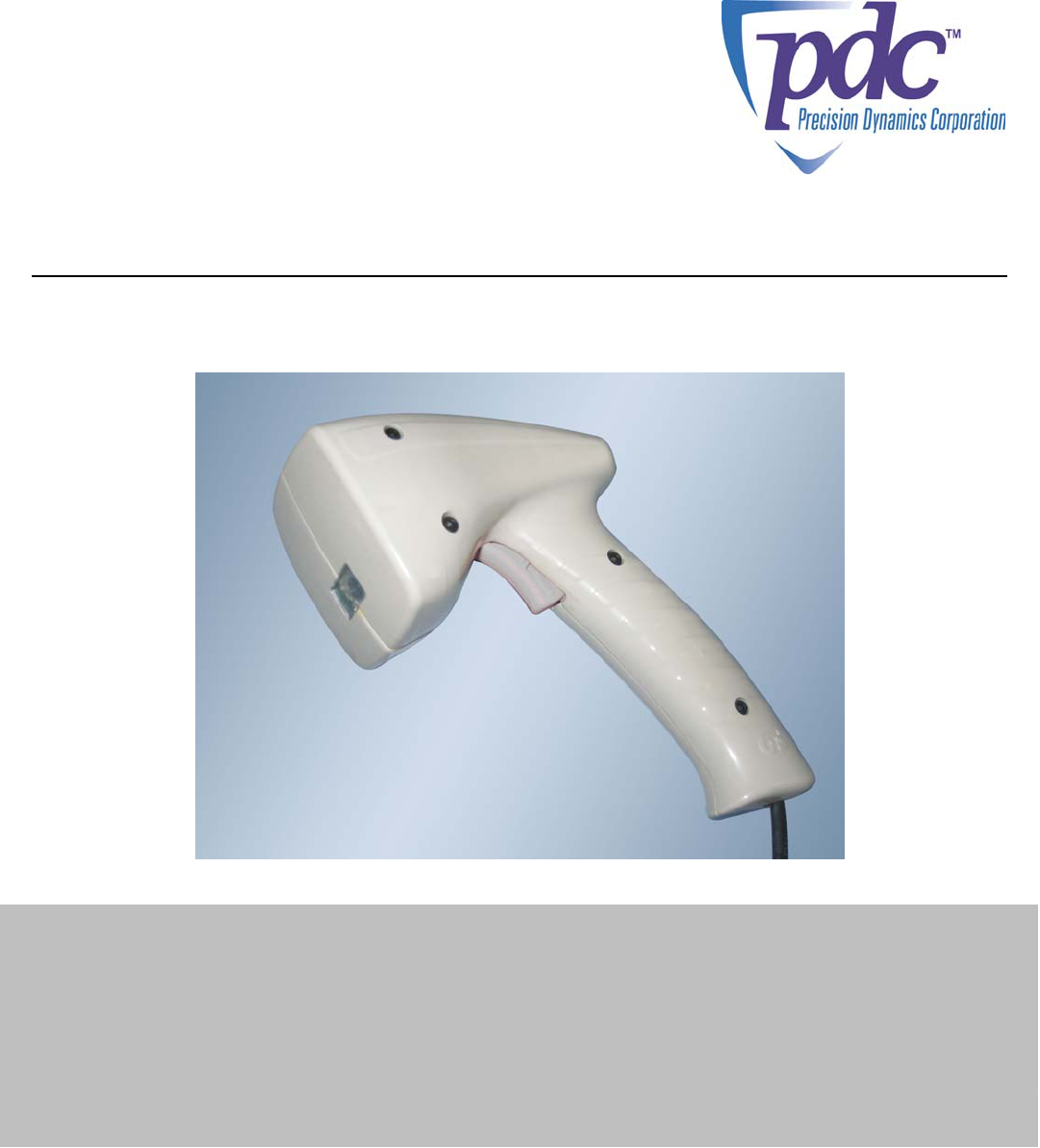
DR1000TM
Dual Reader
User Manual
©2005 Precision Dynamics Corporation
DR1000 User Manual Precision Dynamics Corp.
Page 2 of 44
TABLE OF CONTENTS
SAFETY PRECAUTIONS & IMPORTANT SAFETY INSTRUCTIONS.............................. 5
1 PURPOSE OF THIS DOCUMENT ........................................................................................... 8
2 PRODUCT OVERVIEW ............................................................................................................... 9
2.1 GENERAL DESCRIPTION.................................................................................................................... 9
2.2 FEATURES ......................................................................................................................................... 9
2.3 DR1000 RFID TAG COMPATIBILITY ............................................................................................... 10
2.4 DR1000 BARCODE COMPATIBILITY................................................................................................. 10
3 MODELS AND MODES OF OPERATION........................................................................... 11
3.1 COMMAND MODE ........................................................................................................................... 11
3.2 TRIGGER MODE .............................................................................................................................. 12
3.2.1 Scan Sequence................................................................................................................ 12
3.2.2 Barcode Data Style........................................................................................................ 13
3.2.3 RFID Data Style.............................................................................................................. 13
3.2.4 Keyboard Emulation (Wedge) ................................................................................... 14
3.3 SCANNING AN RFID TAG ............................................................................................................... 14
3.4 SCANNING A BARCODE ................................................................................................................... 14
3.5 FIELD INTERPRETATION ................................................................................................................. 14
3.5.1 Overview ........................................................................................................................... 14
3.5.2 Field Interpretation Arrays ......................................................................................... 15
3.5.3 Keyboard emulation and serial differences.......................................................... 16
3.5.4 Error Conditions and Handling.................................................................................. 16
4 POWER AND HOST INTERFACE CONNECTIONS....................................................... 18
4.1 POWER ............................................................................................................................................ 18
4.2 USB ................................................................................................................................................ 18
4.3 RS-232 ............................................................................................................................................ 19
4.4 PS/2................................................................................................................................................ 21
5 USER INTERFACES................................................................................................................... 23
5.1 LEDS.............................................................................................................................................. 23
5.2 BEEPER ........................................................................................................................................... 23
5.3 TRIGGER ......................................................................................................................................... 23
6 FIRMWARE UPGRADES .......................................................................................................... 24
APPENDIX 1 - BaRS SOFTWARE ................................................................................................. 25
INSTALLING BARS .................................................................................................................................... 25
INSTALLING USB SERIAL COMMUNICATION DRIVERS .............................................................................. 25
STARTING THE BARS APPLICATION .......................................................................................................... 27
MAIN TOOL BAR....................................................................................................................................... 27
APPLICATION CONFIGURATION................................................................................................................ 31
Serial Port ....................................................................................................................................... 31
Baud Rate........................................................................................................................................ 32
Barcode Scan Timeout ............................................................................................................... 32
SCANNER SETTINGS.................................................................................................................................. 32
Baud Rate........................................................................................................................................ 32
USB Mode........................................................................................................................................ 33
Barcode Scan Timeout (COMMAND MODE only).................................................................... 34
DR1000 User Manual Precision Dynamics Corp.
Page 3 of 44
Beeper .............................................................................................................................................. 34
Scan Sequence.............................................................................................................................. 34
RFID Tag Type............................................................................................................................... 34
Barcode Data Style...................................................................................................................... 34
RFID Data Style ............................................................................................................................ 34
Trigger Notification (COMMAND MODE only) .......................................................................... 35
Scanner Serial Number.............................................................................................................. 35
Scanner Firmware Version........................................................................................................ 35
Field Interpretations.................................................................................................................... 36
Apply To Scanner ......................................................................................................................... 37
Read From Scanner..................................................................................................................... 37
Load From File............................................................................................................................... 37
Save To File.................................................................................................................................... 37
Advanced......................................................................................................................................... 37
RFF VIEW................................................................................................................................................. 38
DATA VIEW .............................................................................................................................................. 38
Raw RFID......................................................................................................................................... 39
Formatted RFID............................................................................................................................. 39
Barcode ............................................................................................................................................ 39
Trigger Operation ......................................................................................................................... 39
FORMATTED READ FORM ......................................................................................................................... 40
APPENDIX 2 - DR1000 DEMONSTRATION.............................................................................. 41
START THE APPLICATION.......................................................................................................................... 41
PREPARING THE RFID TAG...................................................................................................................... 41
APPLYING THE SCANNER CONFIGURATIONS ............................................................................................ 42
KEYBOARD EMULATION READ (USB AND PS/2 VERSIONS)..................................................................... 42
CHANGING THE SCANNER CONFIGURATION (USB VERSION)................................................................... 43
COMMAND MODE READ........................................................................................................................... 44
TRIGGER EVENTS ..................................................................................................................................... 44
DR1000 User Manual Precision Dynamics Corp.
Page 4 of 44
© Copyright 2005
Precision Dynamics Corporation
All Rights Reserved
No portion of this manual may be copied, photocopied, transcribed or otherwise duplicated
for commercial purposes except with the express and written permission of the Precision
Dynamics Corporation and/or its legally authorized representative.
DISCLAIMER
The operations represented in this manual are for guideline purposes only and in no way are
to be construed as a warranty or other operation obligation, legal or otherwise. For
information on warranty, service and other legal rights and obligations regarding the product
covered by this manual, refer to the warranty/service information provided by the seller or
reseller of this product.
Safety Precautions & Warnings
Page 5 of 44
Safety Precautions & Important
Safety Instructions
CAUTION
RISK OF ELECTRIC SHOCK
DO NOT OPEN
CAUTION: TO REDUCE THE RISK
OF ELECTRIC SHOCK
DO NOT REMOVE THE COVER (OR BACK).
NO USER-SERVICEABLE PARTS INSIDE.
REFER SERVICING TO QUALIFIED SERVICE PERSONNEL.
The lightening flash with arrowhead symbol within an equilateral triangle is
intended to alert the user to the presence of uninsulated dangerous voltage within
the product’s enclosure that may be of sufficient magnitude to constitute a risk of
electric shock to persons.
The exclamation point within an equilateral triangle is intended to alert the user to
the presence of important operating and maintenance (servicing) instructions in
the literature accompanying the product..
USE OF THIS PRODUCT IN A MANNER OTHER THAN DEFINED
IN THIS MANUAL MANY CAUSE DAMAGE TO EQUIPMENT
OR INJURY TO PERSONNEL.
FCC WARNING: This equipment has been tested and found to comply with the
limits for a device pursuant to Part 15 of the FCC Rules, to wit, operation is
subject to the following two conditions:
1. This device may not cause harmful interference, and
2. This device must accept any interference received, including interference that
may cause undesired operations
Safety Precautions & Warnings
Page 6 of 44
These limits are designed to provide reasonable protection against harmful
interference when the equipment is operated in a commercial environment. This
equipment generates, uses, and can radiate radio frequency energy and, if not
installed and used in accordance with the instruction manual, may cause harmful
interference to radio communications. However, there is no guarantee that this
interference will not occur in a particular installation. If this product does cause
harmful interference to radio or television or other wireless reception, which can
be determined by turning the product off and on, the user is encouraged to
correct the interference by one or more of the following measures:
• Reorient or relocate this product or the unit experiencing interference.
• Increase the separation between this product and the unit experiencing
interference.
• Connect this product into an outlet or circuit different from that to which
the unit experiencing interference is connected.
• Consult the dealer for technical support.
Changes or modifications to this equipment may cause harmful interference unless
the modifications are expressly approved in the instruction manual. The user
could lose the authority to operate this equipment if an unauthorized change or
modification is made.
Warnings & Safety Precautions
The DR1000 is designed and manufactured to provide long, trouble-free
service. No maintenance other than cleaning is required. Use a soft dry cloth to
clean the surface. Never use solvents such as alcohol or thinner to clean the
surface.
To ensure your safety when installing this equipment, for operating safety and to
avoid damage to the apparatus, read carefully and observe the following
precautions and instructions:
1. For performance and safety reasons, only the power supplies listed for use with
this equipment should be used.
2. Connect the unit only to a properly rated supply circuit.
3. All wiring external to this product should follow the local wiring codes.
4. This unit is for use in dry locations only. Do not expose the unit to water or
moisture.
5. Do not operate in ambient environments with a temperature greater than
1040F/400C or lower than 410F/50C.
6 Do not open the DR1000. If the unit is damaged in this way, the warranty will
be void. Moreover, there is a risk of shock.
10. Do not attempt to service or repair the DR1000 unit. The unit’s components
are not user serviceable. Only authorized, qualified personnel should service
Safety Precautions & Warnings
Page 7 of 44
this system. The Precision Dynamics Corporation is not liable for any bodily
harm or damage caused if unqualified persons attempt service or open the
cover(s) to any component of the system. Refer all service to authorized
DR1000 service technicians.
To avoid damage and prolong operating life:
• Handle the unit carefully when installing and do not drop.
• Set the unit away from heat, excessive dust and direct sunlight..
• Protect the inside of the unit’s components from liquids. In case of
accident, unplug the console and have the damage serviced by an
authorized technician.
• Do not hit or scratch the unit’s light-sensor window surface as this causes
flaws on the surface of the window and may damage operation.
• Do not connect the PS/2 cable to the host when the 5V power supply is
also connected, as it may damage the DR1000 or the host computer
1: Purpose of the Document
Page 8 of 44
1 Purpose of this Document
The purpose of this document is twofold:
• First, to introduce the user to the capabilities of the DR1000 Dual Reader.
• Second, to enable a user to configure the device to scan RFID tags and
barcode data and send data to a host device as if it were entered from a
keyboard.
This document describes two critical interfaces of the DR1000:
• the User Interface
• the Host Interface
The User Interface consists of the trigger, two multi-color LEDs, and a beeper. The
Host Interface is implemented as a keyboard emulation or ‘wedge’ interface which is
available in the USB and PS/2 models: the DR1000 sends data to the host in the
form of keystrokes, but the host cannot send any information or commands to the
DR1000. In this manner, the DR1000 can be used to input barcode and RFID
data directly into any application which accepts keystrokes. This allows a user to
quickly incorporate the DR1000 into an existing application without requiring any
programming effort.
For users who require functionality beyond what is available with keyboard
emulation, a Software Development Kit (SDK) is available. The SDK includes
user documentation, sample code and both DLL and ActiveX components to
allow a programmer to easily harness the full functionality of the DR1000 Dual
Reader.
2: Product Overview
Page 9 of 44
2 Product Overview
2.1 General Description
The DR1000 Dual Reader is a handheld, tethered barcode/RFID reader for use
with most industry standard linear and 2-D barcode symbols, as well as 13.56
MHz RFID tags and labels. The DR1000 is compatible with ISO 15693
transponders and several previous generation proprietary protocols.
The DR1000 Dual Reader is available with three different interface options:
- USB
- RS-232 (serial)
- PS/2
The Dual Reader allows firmware upgrades in the field. This guarantees a forward
migration path and sound investment as new features and enhancements become
available.
2.2 Features
• Operates from 5V DC
• ISO 15693 compatible
• Flash upgradeable in the field for future product updates
• RFID Read Range: 6.5 inches (16.5 cm) read range with credit card size
tags, 5.0 inches (12.5 cm) with wristband-size tags
• Keyboard emulation operation available with PS/2 and USB models
• User feedback via two multi-color LEDs and a beeper
• Trigger operation – point and scan barcodes and RFID tags
• Host control mode – powerful, easy to use software interface (requires
SDK)

2: Product Overview
Page 10 of 44
2.3 DR1000 RFID Tag Compatibility
The DR1000 Dual Reader supports the RFID tag types and features shown in
Table 1 below. By default, the DR1000 will read all compatible tag types (auto-
detect), but it may be configured to only read a single tag type to optimize
performance.
Table 1 – DR1000 Tag Compatibility
ISO-15693 (-2 and -3 compliant)
Manufacturer Product
Memory
(bits)
Anti-
collision Read Write
Texas Instruments Tag-it HF-I 2048 yes yes yes
Philips I·CODE SLI
(SL2)
1024 yes yes yes
Infineon my-d
SRF55V10P
10k yes yes yes
ST
Microelectronics
LR512 512 yes yes yes
Proprietary
Manufacturer Product
Memory
(bits)
Anti-
collision Read Write
Texas Instruments Tag-it HF 256 yes yes yes
Philips I·CODE (SL1) 512 yes yes yes
Inside Contactless PicoTag 2K 2k no id only no
2.4 DR1000 Barcode Compatibility
The DR1000 Dual Reader decodes the linear and 2-D barcodes listed in Table 2
below:
Table 2 – DR1000 Barcode Compatibility
Linear: 2-Dimensional: Postal:
Code 39
Code 128
Codabar
UPC
EAN
I 2of5
RSS
Code 93
Codablock
PDF417
MicroPDF417
MaxiCode
Data Matrix
QR Code
Aztec
Aztec Mesa
Code 49
UCC Composite
Posnet
Planet Code
BPO 4 State
Canadian 4 State
Japanese Post
Kix

3: Models & Modes of Operation
Page 11 of 44
3 Models and Modes of
Operation
Table 3 lists the three available models and the corresponding modes of
operation. The DR1000 has two (2) operating modes, Trigger Mode and
Command Mode.
Table 3 – DR1000 Models and Modes
USB
(Keyboard
Emulation) 1
USB
(Serial Emulation) 2
[default setting]
RS-232 Serial PS/2
Trigger Mode 3
Keyboard
emulation via
USB
ASCII data via
virtual COM port
ASCII data via
RS-232
connector
Keyboard
emulation via
PS/2 Connector
Command Mode 4 N/A Via virtual COM
port
Via RS-232
connector
Via RS-232
Connector
Power Source Host USB
connection
Host USB
connection
External Power
Supply Adaptor
External Power
Supply Adaptor
or via the Host
PS/2 interface
1 Keyboard emulation mode is automatically entered at power-on if the HID Mode is set to HID and the
trigger is not pulled, or if HID Mode is set to Serial and the trigger is pulled at power-on and then released
(USB model only).
2 Serial Emulation mode is automatically entered at power-on if the HID Mode is set to Serial and the
trigger is not pulled, or if HID Mode is set to HID and the trigger is pulled at power-on and then released
(USB model only).
3 Configurable ASCII read-only mode under DR1000 firmware control.
4 To configure the device for trigger mode operation and/or to perform read and write operations under
application control.
3.1 Command Mode
Command Mode is used to configure a device for trigger mode operation, and/or as
the primary method to control the device. The BaRS utility software may be used
to easily configure the DR1000 for keyboard emulation applications (see Appendix
1 for additional information). Host control of the DR1000 requires programming
which is facilitated by the SDK (sold separately).
As long as the DR1000 has power, Command Mode is active when the trigger is in
the released position. In Command Mode the DR1000 is listening for a command
from the host. It is not required that a host have the capability to send a
command to the DR1000.
NOTE
The DR1000-PS/2 or DR1000 USB in keyboard emulation
can
never
receive a command from a host. The DR1000
USB can receive commands if it is re-initialized in serial
emulation mode. The DR1000-PS/2 can receive commands
if its serial connector is plugged in. Writing to a tag can only
be done in command mode.

3: Models & Modes of Operation
Page 12 of 44
3.2 Trigger Mode
Trigger Mode is designed to read formatted ASCII data from a combination of
RFID or barcode data sources, and supply the data to a host device as if it was
entered from a keyboard. The user may specify up to three events in a Scan
Sequence to capture data from three different RFID or bar code data sources, and
quickly populate multiple text fields of a form without the use of a keyboard.
Trigger Mode is activated when a user pulls the trigger (if Trigger Mode is not
disabled). While in Trigger Mode, the DR1000 begins scanning immediately and
continues to scan until a RFID tag or barcode is read, or until the trigger is
released. The maximum data string length is 1024 bytes. Data strings that exceed
1024 bytes will be truncated.
The operating characteristics of the DR1000, while in Trigger Mode, are defined by
the following parameters: Scan Sequence, RFID Data Style, and Barcode Data
Style. Each parameter may be configured to match the needs of the application.
3.2.1
Scan Sequence
When Scan Sequence is enabled, a maximum of three events may be defined to
capture information from any combination of RFID or barcode data sources. The
possible Scan Sequence options are listed in Table 4. If Scan Sequence is
disabled, Trigger Mode is disabled.
Table 4 – Trigger Mode Setting: Scan Sequence
Disabled
Barcode
RFID
Barcode, RFID (default)
RFID, Barcode
Barcode, Barcode
RFID, RFID
Barcode, Barcode, Barcode
Barcode, Barcode, RFID
Barcode, RFID, Barcode
RFID, Barcode, Barcode
Barcode, RFID, RFID
RFID, RFID, Barcode
RFID, Barcode, RFID
RFID, RFID, RFID

3: Models & Modes of Operation
Page 13 of 44
EXAMPLE
In a hospital, a nurse wishes to administer medication to a patient and must record
the event in an electronic record. The record consists of nurse’s name, medication
information, and patient information. The nurse name and medication
information will be read from two separate barcodes, and the patient information
will be read from a RFID wristband. The Scan Sequence is nurse name (barcode),
patient information (RFID tag), and medication information (barcode). Using the
DR1000 Dual Reader, this information may be scanned into text fields of an
electronic form without using a keyboard. In use, the nurse positions the cursor in
the text box for the nurse’s name, points the DR1000 at the nurse’s badge, and
pulls the trigger. The name from the barcode is automatically entered into the text
box. The nurse then repeats this operation to capture the patient and medication
information.
3.2.2
Barcode Data Style
Barcode Data Style defines how barcode data is transmitted back to the host. The
DR1000 has two options as indicated in Table 5 below.
By default, the Complete Barcode Data option causes the DR1000 to
read the barcode and send the entire data string to the host.
If the DR1000 is configured for Use Field Interpretation, barcode data
may be parsed into separate data fields (multiple text boxes), and sent to
the host with header and trailer characters, if desired. The header and
trailer characters may contain tabs, carriage returns or line-feeds to
navigate between different text boxes by reading only one barcode.
The Barcode Data Style setting applies to all barcodes defined by the Scan Sequence.
Table 5 – Trigger Mode Setting: Barcode Data Style
Complete Barcode Data (default)
Use Field Interpretation
3.2.3
RFID Data Style
RFID Data Style defines the content and structure of RFID data transmitted back
to the host. The RFID Data Style options are identified in Table 6 below. The Tag
UID setting allows the DR1000 to read and transmit the RFID tag Unique
IDentification (UID) number. RFID Data Style also supports Field Interpretation
and operates in the same way as Barcode Data Style. The RFID Data Style setting
applies to all RFID tags defined by the Scan Sequence.
Table 6 – Trigger Mode Setting: RFID Data Style
UID Only
Data Only (default)
UID and Data
Use Field Interpretation
In general, RFID tag ASCII data is read and transmitted to the host until a NUL
character is encountered. If multiple tags are present within the read-range of the
dual reader, the DR1000 will only read the UID of the first tag it detects.

3: Models & Modes of Operation
Page 14 of 44
3.2.4
Keyboard Emulation (Wedge)
In PS/2 or USB Keyboard Emulation Mode, the DR1000 will map each byte value of
a data string to an equivalent keystroke. Only valid ASCII characters are output to
the host. Any other barcode or RFID tag data not part of the ASCII character set
is ignored. That is, the following ASCII values are discarded: SOH, STX, ETX,
EOT, ENA, ACK, BEL, BS, VT, FF, SO, SI, DLE, DC1, DC2, DC3, DC4,
NAK, SYN, ETB, CAN, EM, SUB, FS, GS, RS, US, DEL. Also, any byte value
with the MSB set (high bit) is ignored. When a NUL character is encountered, the
string is terminated and any additional characters are ignored.
ASCII chart
0 1 2 3 4 5 6 7 8 9 A B C D E F
0 HT LF CR
1 ESC
2 SP ! " # $ % & ' ( ) * + , - . /
3 0 1 2 3 4 5 6 7 8 9 : ; < = > ?
4 @ A B C D E F G H I J K L M N O
5 P Q R S T U V W X Y Z [ \ ] ^ _
6 ` a b c d e f g h i j k l m n o
7 p q r s t u v w x y z { | } ~
3.3 Scanning an RFID Tag
A RFID tag must be oriented parallel to the face of the DR1000 at no more than
5.0 inches for a wristband sized tag and 6.5 inches for a credit card sized tag.
Upon a trigger pull, the DR1000 will scan for a RFID tag until a RFID tag is read
or the trigger is released. The DR1000 outputs all data to the host as soon as it is
read. However, the next scan cannot start until the trigger is released and pulled
again.
3.4 Scanning a Barcode
The proper method for scanning a barcode is to hold the face of the DR1000 4-6
inches from the barcode. When the trigger is depressed, a red or green light bar
darker than the surrounding red laser appears on or over the barcode. The bar
should line up with the barcode horizontally. The DR1000 continuously scans for
a barcode until one is read or the trigger is released.
3.5 Field Interpretation
3.5.1
Overview
Field Interpretation is a useful and powerful feature of the DR1000 to
automatically parse a data string into multiple segments, or append fixed
characters before or after a data string. This capability allows a user to
automatically populate and navigate multiple text boxes in a form, simply by
scanning a single barcode or RFID tag.

3: Models & Modes of Operation
Page 15 of 44
EXAMPLE
A single barcode is scanned which has 10 characters of name, 10 characters of
social security number, and 8 characters of date. An example data stream might
be First_Name123456789002142005. The data is scanned into a form that has
Name, SSN and Date text boxes. A tab character will navigate between the 3 text
boxes. It is desired to scan the data into the form as:
Name: First_Name
SSN: 123-456-7890
Date: 02/14/2005
This can be handled readily using Field Interpretation arrays.
In this case, the BaRS program allows the field interpretation parameters to be
configured. There are two components to interpretation arrays; how to store
interpretation arrays into the DR1000, and how the DR1000 will output data
according to the interpretation arrays stored. This section will detail both how to
store interpretation array data into the DR1000, how the DR1000 will output data
according to the interpretation array stored, and also error conditions that the
DR1000 can encounter and its responses.
3.5.2
Field Interpretation Arrays
A raw data string can be parsed into multiple segments by defining field
interpretation arrays. A field interpretation array consists of individual records (up
to 64), each defined by the following parameters:
Field Address – the starting location of the data string.
Field Length – the maximum length of the data, in number of bytes, to output
starting at the field address value. The data is output sequentially from the Field
Address to the Field Address + Field Length-1. Field length can be any length from
0x0000 to 0x03FF. A field length value of 0x0000 indicates that field
interpretation is terminated, and that the last field sent to the host was the last
field to be sent for the current scan.
Header – a 4-character field sent at the beginning of each field. Each field can
have a unique header and can be 0 to 4 characters.
Trailer – a 4-character field sent at the end of each field. Each field can have a
unique trailer and can be 0 to 4 characters.
All interpretation array data is output in the following format, where H stands for
header, T stands for trailer, and FxL is the data of size length L in Field X.
H1 F1L T1 H2 F2L T2 H3 F3L T3 …... HN F(N < 64)L TN
Field 1 ----------------------------------------------------------------------------- > Field N

3: Models & Modes of Operation
Page 16 of 44
EXAMPLE
In the previous example, the barcode data stream is broken into seven segments
as shown in the following chart.
Field
Address
Field
Length
Header Trailer Comment
0 10 <tab>
Output name followed by a tab
character to move to the SSN text
box
10 3 -
Insert a ‘-‘ between the 3rd & 4th
digit
13 3 -
Insert a ‘-‘ between the 6th & 7th
digit
16 4 <tab>
Output last 4 SSN digits followed
by a tab character to move to the
Date text box
20 2 /
Insert a ‘/‘ between the day and
month
22 2 /
Insert a ‘/‘ between the month
and year
24 4
This table is entered using the BaRS software utility and downloaded to the
DR1000. In operation, the user positions the cursor on the Name text box and
scans the barcode to populate each field in the form.
A field interpretation array is terminated when it encounters a field with a length
of 0. The field address does not have to be sequential. That is, the fields in the
interpretation array can jump to different addresses in the scanned data. The
DR1000 supports up to three separate interpretation arrays, one for each scan that
is enabled by the Scan Sequence parameter.
NOTE
The field interpretation may be written to the DR1000, but it
cannot be read back from the device. For this reason, it is
important to use the BaRS software’s Save to File feature to
save the configuration before exiting the program.
3.5.3
Keyboard emulation and serial differences
In the case of a PS/2 unit or a USB unit in keyboard emulation mode, only normal
ASCII characters can be transferred to the host. There are no limitations to a RS-
232 or USB unit in serial emulation mode. All raw bytes will be sent to a COM
port on the host.
3.5.4
Error Conditions and Handling
There are several error conditions that can occur when a DR1000 outputs data
according to field interpretation arrays. The DR1000, in most instances, will
output a trailer when it encounters an error and indicate to the user an error
occurred via the LEDs and beeper. The errors and the DR1000’s handling of
these errors are described below:
3: Models & Modes of Operation
Page 17 of 44
Error: The Field Address attempts to address data outside the scanned data range.
For example, an error occurs if the DR1000 scanned 50 bytes of data from an
RFID tag or barcode and the field address pointed to location 51.
DR1000 Response: The DR1000 will output the header and the trailer and
indicate to the user an error occurred via the LEDs and/or the beeper.
Error: The Field Address attempts to address data inside the scanned data range,
but the Field Length exceeds the available scanned data in the DR1000 data
buffer. That is, if the DR1000 scanned 50 bytes of data from an RFID tag or
barcode and the address pointed to location 49 but had a Field Length of 15.
DR1000 Response: The DR1000 will output data until it gets to the end of
available data, and then output the trailer. An error will be indicated to the
operator via the LEDs and/or beeper.

4: Power and Host Interface Connections
Page 18 of 44
4 Power and Host Interface
Connections
This section describes the available host interfaces, their specific modes of
operation and differences, and power configurations for each model.
4.1 Power
Depending on the interface type, the DR1000 receives power from the PS/2 port,
from the USB port, or from a separate 5V power supply. The maximum current
required by the DR1000 is 450mA at 5V. The DR1000 operates optimally at 5V,
with some read-range degradation at lower supply voltages.
4.2 USB
The USB model supports two modes of operation: serial communication and
keyboard emulation. The current mode of operation may be determined by
viewing the Windows Device Manager. If the DR1000 is in keyboard emulation
mode, the device will register with the operating system as a Human Interface Device
(HID). Conversely, if the DR1000 is in serial communication mode, the device
will register with the operating system as a serial device, with the emulated serial
port number identified in the Device Manager.
If the DR1000 is in keyboard emulation (HID) mode, it cannot receive
commands from the host. Therefore, there is a method to change the DR1000
from keyboard emulation mode to serial communication mode without using a
host command:
1. Disconnect the USB cable from the host.
2. Depress and hold the trigger of the DR1000.
3. Connect the USB cable to the host.
If the trigger of the DR1000 is depressed during startup (connection to the host),
the DR1000 will toggle modes based on the HID mode previously stored in
memory. For example, if the HID mode is set to serial communication and the
trigger is depressed during startup, the DR1000 will switch modes and startup in
keyboard emulation mode, and vice versa.
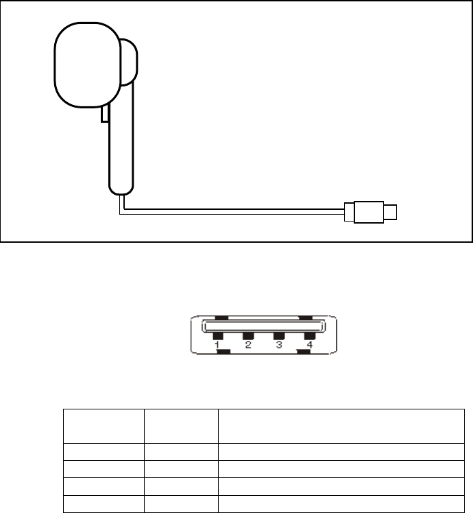
The USB model has a Type A male USB connector at the end of a 2-meter cable,
tethered and permanently connected at the DR1000 side. The DR1000 is powered
from the USB host via the USB cable. The Type A male USB connector mates
with any standard host device with a Type A female USB connector.
4: Power and Host Interface Connections
Page 19 of 44
Table 7 - USB Power and Communications Connection
Table 8 - Mating face USB type A female (host)
Table 9 USB Connector Pin Assignments
Pin
Number
Pin
Name
Pin
Description
1 +5 Vcc Supply for USB device
2 -D Negative differential data signal
3 +D Positive differential data signal
4 GND Ground for USB device
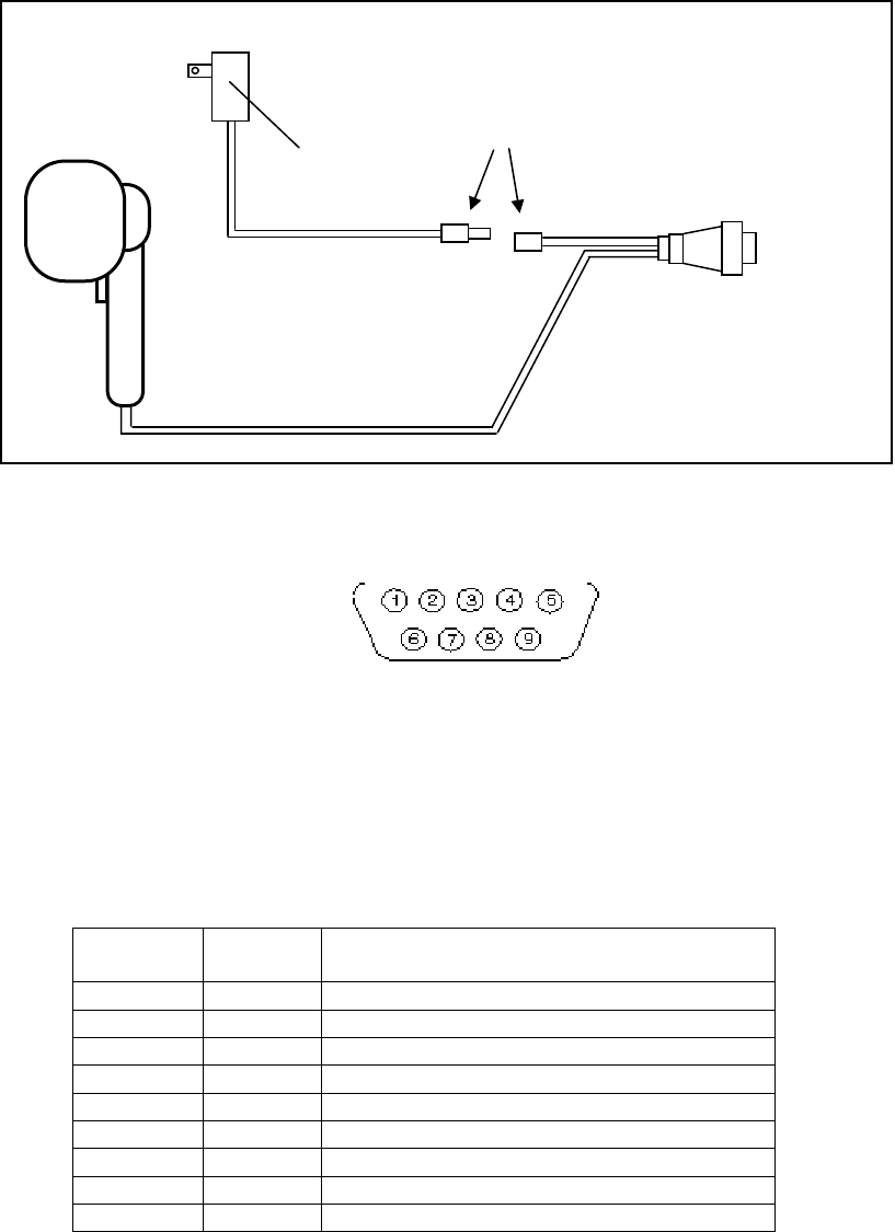
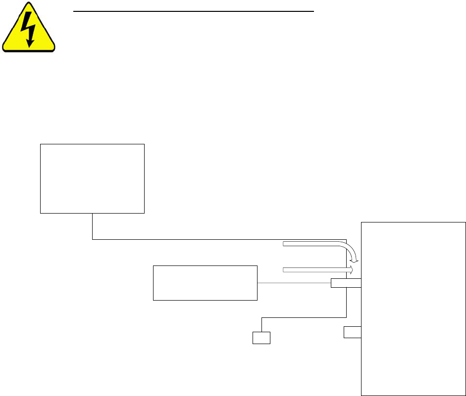
4.3 RS-232
For the RS-232 model, the power supply must be connected to an active power
outlet, and the RS-232 cable must be connected to the host computer.
The RS-232 model has a female DB-9 connector with integrated power dongle
input connector at the end of a 2-meter cable, tethered and permanently
connected at the DR1000 side. The 2.5mm x 5.5mm center positive power jack
option at the end of the power dongle requires power input from an external 5V
power supply (wall transformer).
The female DB-9 connector mates with any standard host device with a male DB-
9 connector.
DR1000-USB USB Type A Male
(To Host)
4: Power and Host Interface Connections
Page 20 of 44
Table 10 – RS232 Power and Communications Connections
Table 11 - Mating face of DB9 male (host)
Table 12 below identifies the pin assignments for the RS-232 DB9 connector.
The DR1000 communication interface supports baud rates of 9600, 19200, 38400,
57600 and 115200 with 8 data bits, 1 stop bit and no parity. Flow control is not
supported. The default baud rate is 9600.
Table 12 RS-232 DB9 Pin Assignments
Pin
Number
Pin
Name
Pin
Description
1
2 Tx_232 RS-232 transmit to host
3 Rx_232 RS-232 receive from host
4
5 GND Ground for RS-232 host
6
7
8
9
2.5mm x 5.5mm
5V DC, 1A
Center Positive
DR1000-232
DB9 Female
(To Host)
90 - 240V AC
50 - 60 Hz
PS 5V
4: Power and Host Interface Connections
Page 21 of 44
4.4 PS/2
The PS/2 model is intended for use with applications that require keyboard
emulation only. However, since the DR1000 cannot receive configuration
commands while connected to the PS/2 port, the PS/2 model is also equipped
with a RS-232 cable. Follow the connection instructions below to configure a
PS/2 model:
1. Disconnect the PS/2 cable from the host computer.
2. Connect the RS-232 cable to a host computer.
3. Connect the 5V power supply into a power outlet and connect the power
supply to the RS-232 dongle.
WARNING:
Do not connect the PS/2 cable to the host when
the 5V power supply is also connected, as it may
damage the DR1000 or the host computer.
During normal operation, the PS/2 model is powered from the host computer via
the PS/2 port. The 6-pin mini-DIN male connector at the end of the DR1000
PS/2 cable connects to any standard host device with a 6-pin mini-DIN female
connector.
Table 13 - PS/2 Operational - Power and Communications Connection
PS
/
2 Operational configuration
DR1000
power on PS
/
2 cable
host
PS
/ 2
RS
-
232
not
connected
PS/2 keyboard
4: Power and Host Interface Connections
Page 22 of 44
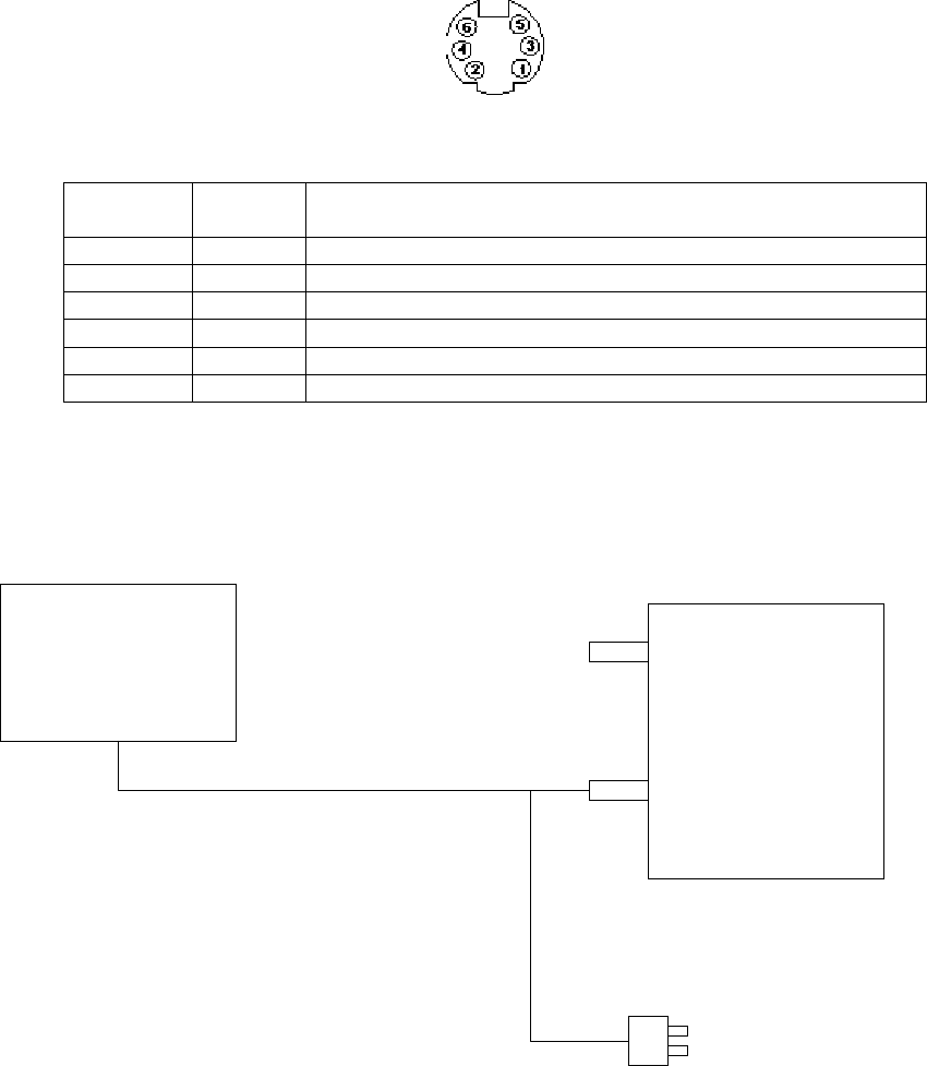
Table 14 - Mating face of 6-pin mini-DIN female
Table 15 PS/2 Connector Pin Assignments
Pin
Number
Pin
Name
Pin
Description
1 Data
Data signal on PS/2 Bus
2 N/C Not Connected (Can be used for alternate Data Signal)
3 GND
PS/2 Supply Ground
4 +5 Vcc PS/2 Supply
5 CLK Data Clock on PS/2 Bus
6 N/C Not connected (Can be used for alternate Clock Signal)
Table 16 - PS/2 Configuration with RS-232 Communication and
Power Connections
DR1000
host
RS
-232
power on cable
PS/2
5V power supply
(connect to power outlet)l
5: User Interfaces
Page 23 of 44
5 User Interfaces
The DR1000 has a trigger, a beeper and two LEDs for feedback and interaction
with the device.
5.1 LEDs
The DR1000 has two multi-colored LEDs (red, green or yellow) controlled by the
device firmware or via host control. In Trigger Mode, the LEDs are controlled by
the device firmware in the following manner:
1. The top LED (closest to the reader face) indicates “scanning in process”.
2. The bottom LED (closest to the handle) indicates the “read” status.
3. When the trigger is not pulled, the “scanning” LED is off.
4. When the trigger is pulled, the “scanning” LED is green and remains green until
either a valid read is processed, or the trigger is released. At this point, the
LED turns off.
5. When a scan is complete, the color of the “read” LED turns to either green or
red depending on whether the read passed or failed, respectively. The LED
remains that color until the trigger is pressed again. When the trigger is
pressed, the LED turns off and remains off until a valid barcode or RFID tag
is read, or the trigger is released.
The color and operation of each LED is fully configurable if the DR1000 is under
host control. The configuration instructions are beyond the scope of this
document, but are fully explained in the SDK documentation.
5.2 Beeper
At power on, a low-frequency beep indicates an error condition in the RFID or
the barcode reader modules. In Trigger Mode, a beep indicates a successful read.
This feature may be disabled, but is on by default.
5.3 Trigger
The DR1000 has a single trigger to activate the DR1000 in a typical “point and
scan” application. During Trigger Mode, the DR1000 outputs all data immediately
after a successful read, and the next scan cannot start until the trigger is released
and pulled again.
6: Firmware Upgrades
Page 24 of 44
6 Firmware Upgrades
The DR1000 has a built-in boot loader to allow firmware upgrades in the field
through a software interface. Complete instructions will be included to support
future firmware upgrades.
Appendix1 – BaRs Software
Page 25 of 44
Appendix 1 - BaRS Software
The BaRS software application is a powerful tool that allows a user to configure
the DR1000 Dual Reader for a specific application, and also demonstrate the
advanced capabilities of the device through a hands-on example. The remainder of
this manual will fully explain the features and operation of the BaRS software
application.
Installing BaRS
The BaRS application software can be installed on any Microsoft Windows XP
and 2000 based personal computer. Insert the BaRS Software CD into the
computer and click on the INSTALL BaRS button to begin the installation
process. Follow the instructions on the screen.
If a USB version of the DR1000 is to be used with the BaRS application or any
host application, the USB serial port emulation drivers must be installed on the
host computer to enable serial communication with the DR1000. This driver
package is included with the BaRS Software CD.
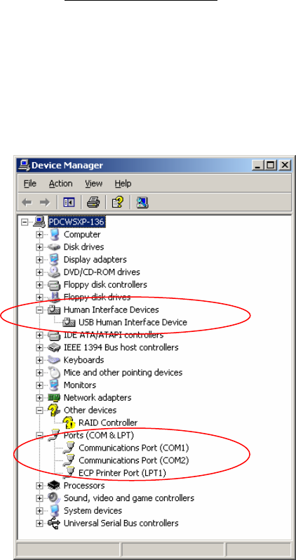
Installing USB Serial Communication Drivers
Once BaRS has been installed, follow the instructions below to install the USB
serial communication drivers. The USB serial emulation drivers are required for
USB models only.
1. Insert the DR1000’s USB connector into the appropriate slot on the host
computer.
2. Open the Windows Device Manager. (Right click on My Computer,
select Properties, select the Hardware tab, click on the Device Manager
button)
3. Find the Human Interface Device key related to USB to Serial and
right click on it. (Select Human Interface Devices, right click on USB Human
Interface Device)
4. Select update driver.
5. Select “Install from list from specific location” and click Next.
6. Select “Don’t search, I will choose the driver to install”. Then click
Next.
7. Select Have Disk. Click Browse.

Appendix1 – BaRs Software
Page 26 of 44
8. Navigate to C:\Program Files\Precision Dynamics
Corporation\BaRS and select the hidcom.inf file. Click Open and then
click OK.
NOTE
If an error message appears at this point, the
DR1000 may be set for keyboard emulation mode.
In this case, disconnect the USB from the host, pull
the trigger on the DR1000, re-connect the USB to
the host and release the trigger. Return to step 2.
9. Select “Cypress USB-HID->COM device” and click Next.
10. If a dialog box appears warning about the driver, click on the Continue-
Anyway button. When the installation completes, click on Finish.
11. The Device Manager window will now reappear with the Ports (COM &
LPT) section highlighted (Cypress USB-HID->COM device
(COMn). Make note of which COM port has been assigned as this will
be needed later.
12. Select File and then Exit to close the Device Manager window.

Appendix1 – BaRs Software
Page 27 of 44
Starting the BaRS Application
During the installation of the BaRS software application, two shortcuts are
installed on the host computer, one on the Desktop, and one in the Windows
Start menu. To run the BaRS application, double-click on the BaRS shortcut on
the Desktop, or select the BaRS shortcut from the Start menu. The following
opening screen of the application will appear.
To exit the application, select “File | Exit” from the menu bar.
Main Tool Bar
The Main Tool Bar contains the icons to activate each of the functions of the
BaRS software. Each button and associated function is described in detail below.
The Open RFF File button allows the user to open an RFF file and apply
it to the RFF view of the application. RFF view is an advanced feature of the
BaRS application. RFF files are XML-based files that define the format of the
displayed form and the RFID data read from a RFID tag. The details of how RFF
files are created and used is outside the scope of this document, however, several
samples of RFF files are provided for demonstration purposes.
Open RFF File
Appendix1 – BaRs Software
Page 28 of 44
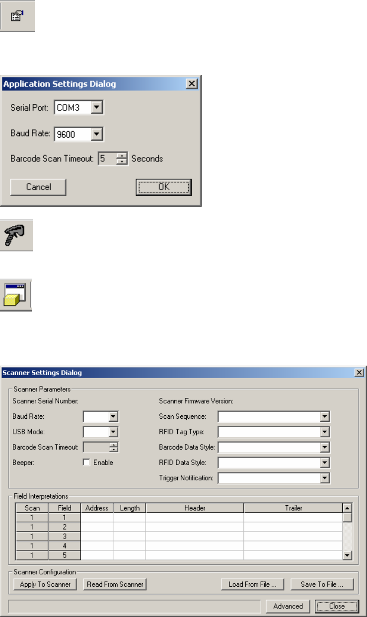
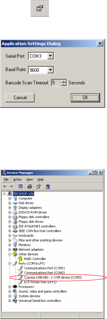
The Application Settings button opens the Application Settings dialog
box and allows the user to set the desired serial port, baud rate, and barcode scan
timeout duration.
The Start Scanner button initializes serial communication between the
DR1000 Dual Reader and the host computer.
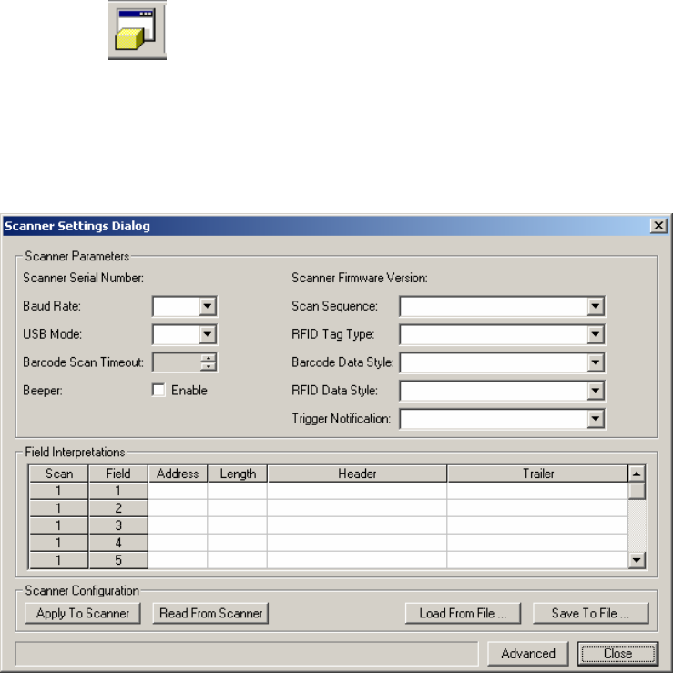
The Scanner Settings button opens the Scanner Settings dialog box to allow
the user to configure the DR1000 Dual Reader for many of its advanced features.
Each configuration parameter of the DR1000 is explained in later sections of this
document.
Application Settings
Start Scanner
Scanner Settings
Appendix1 – BaRs Software
Page 29 of 44
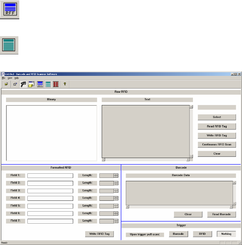
The RFF View button displays the RFF file that was opened and applied
to the application.
The Data View button displays the data view of the application. This view
exercises many of the features of the DR1000 Dual Reader.
RFF View
Data View
Appendix1 – BaRs Software
Page 30 of 44
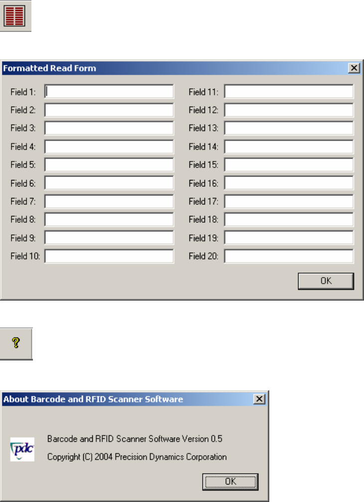
The Form Dialog button opens a Form dialog box used to demonstrate
the keyboard emulation feature of the DR1000 Dual Reader.
The About button identifies the application name, version, and copyright
statement.
Form Dialog
About
Appendix1 – BaRs Software
Page 31 of 44
Application Configuration
Click on the Application Settings button to open the dialog box as
shown below. The serial port, baud rate, and barcode scan timeout duration may
be set as follows:
Serial Port
The Serial Port setting must match the COM port assigned by the operating
system, either the RS-232 port address, typically COM 1, or the emulated serial
port number if the DR1000 is connected via USB. The emulated port number can
be found by exploring the Device Manager of the operating system. Use the arrow
at the right of the control to select the appropriate serial port.
Appendix1 – BaRs Software
Page 32 of 44
Baud Rate
The Baud Rate setting controls the communication speed with the DR1000. The
baud rate must match the baud rate setting of the DR1000 as explained in later
sections. The default setting is 9600 baud.
Barcode Scan Timeout
The Barcode Scan Timeout setting defines the maximum length of time (in
seconds) the BaRS software waits for the DR1000 to read a barcode. This setting
must match the corresponding setting of the DR1000 as described in later
sections. The value may be incremented or decremented using the arrows at the
right side of the control.
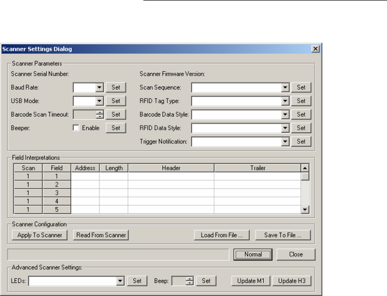
Scanner Settings
Click on the Scanner Settings button to open the Scanner Settings dialog
box and configure the DR1000 for a specific application. Note that any number
of configurations may be saved to a file for later recall and download to the
DR1000. Once a configuration set is applied to the DR1000, it is stored in the
device memory and preserved over a power cycle. It is not necessary to reapply
the Scanner Settings unless a change is desired.
Baud Rate
The Baud Rate setting defines the serial communication rate of the DR1000 with
the host system. This parameter must match the baud rate of the application.
Appendix1 – BaRs Software
Page 33 of 44
USB Mode
The USB model of the DR1000 can operate in either a keyboard emulation mode,
called “HID” (Human Interface Device), or in a serial communication mode. This
setting applies to the USB Mode only and does not affect the operation of the RS-
232 or PS/2 models.
HID (USB model only)
If the USB mode is set to ‘HID’ and the DR1000 is connected to the host
computer, the dual reader will register as a “Human Interface Device” with
the operating system. The DR1000 may be registered with the operating
system as a serial device by holding the trigger in the pulled position
before connecting the device to the host computer, followed by releasing
the trigger after the connection is made.
Conversely, if the USB mode is set to ‘Serial’ and the DR1000 is connected
to the host computer, the dual reader will register as a serial device with
the operating system. The DR1000 may be registered with the operating
system as a Human Interface Device by holding the trigger in the pulled
position before connecting the device to the host computer, followed by
releasing the trigger after the connection is made.

Appendix1 – BaRs Software
Page 34 of 44
Barcode Scan Timeout (C
OMMAND
M
ODE
only)
The Barcode Scan Timeout specifies the length of time (in seconds) the
DR1000 will attempt to read a barcode before terminating the operation. This
parameter must match the Barcode Scan Timeout setting in the Application
Settings described above. The value may be incremented or decremented using
the arrow to the right of the control.
Beeper
The Beeper check box specifies whether the DR1000 beeper is enabled or
disabled.
Scan Sequence
This parameter sets the scanning sequence of the dual reader when the trigger is
pulled. The Scan Sequence and the Trigger Notification parameters are
interrelated, and should be set appropriately.
If Trigger Notification is set to anything other than “None”, the Scan Sequence
parameter should be set to “Disable”.
If Trigger Notification is set to “None”, then the user can specify the action the
dual reader should take when trigger is pulled.
EXAMPLE
Upon the first trigger pull, the dual reader should scan a barcode, and upon the second trigger pull
the dual reader should scan an RFID tag, and repeat the sequence again.
RFID Tag Type
The BaRS software application is only capable of reading and writing to RFID
tags that meet the ISO 15693 protocol. If the DR1000 is intended for use with
other
tag types, a Software Development Kit is available.
Barcode Data Style
Upon reading the barcode data, the DR1000 Dual Reader is capable of sending
the complete raw data stream to the host computer, or applying the “Field
Interpretations” before sending the data to the host computer. Select the
appropriate action to match the application.
RFID Data Style
Upon reading the RFID data, the DR1000 is capable of sending the tag UID to
the host computer, sending the RFID data to the host computer, sending the tag
UID and data to the host computer, or applying the “Field Interpretations” before
sending the data to the host computer. Select the appropriate action to match the
application.

Appendix1 – BaRs Software
Page 35 of 44
Trigger Notification (C
OMMAND
M
ODE
only)
The DR1000 may be configured to send notification to the host computer upon
trigger actions by the operator.
NOTE
If Trigger Notification is set to anything other than
“None”, then the Scan Sequence must be set to
“Disable”.
Scanner Serial Number
The Scanner Serial Number is a read-only parameter from the DR1000. This is
a factory-programmed serial number and is displayed in the Scanner Settings
dialog box if a DR1000 is properly connected to a host computer.
Scanner Firmware Version
The Scanner Firmware Version is displayed in the Scanner Settings dialog box if
a DR1000 is properly connected to a host computer.
Appendix1 – BaRs Software
Page 36 of 44
Field Interpretations
Field Interpretations are a set of user-defined formatting statements
applied by the DR1000 Dual Reader to the data stream read from a barcode
or RFID tag before it is sent to the host computer. There are three sets of
sixty-four field interpretations available. Each set will apply the template to the
scanned data based on the Scan Sequence settings.
EXAMPLE
If the Scan Sequence is set to “Barcode RFID”, the first sixty-four interpretation fields labeled with
“Scan” number “1” are applied to the barcode data, and the next sixty-four interpretation fields
labeled with “Scan” number “2” are applied to the RFID tag data. In this case the last sixty-four
interpretation fields labeled with “Scan” number “3” are ignored. The same principal applies to
other Scan Sequence settings and interpretation fields, accordingly.
When defining interpretation fields for each Scan
Sequence, it is important that the interpretation
fields are consecutive, and no gap is present within
each sequence.
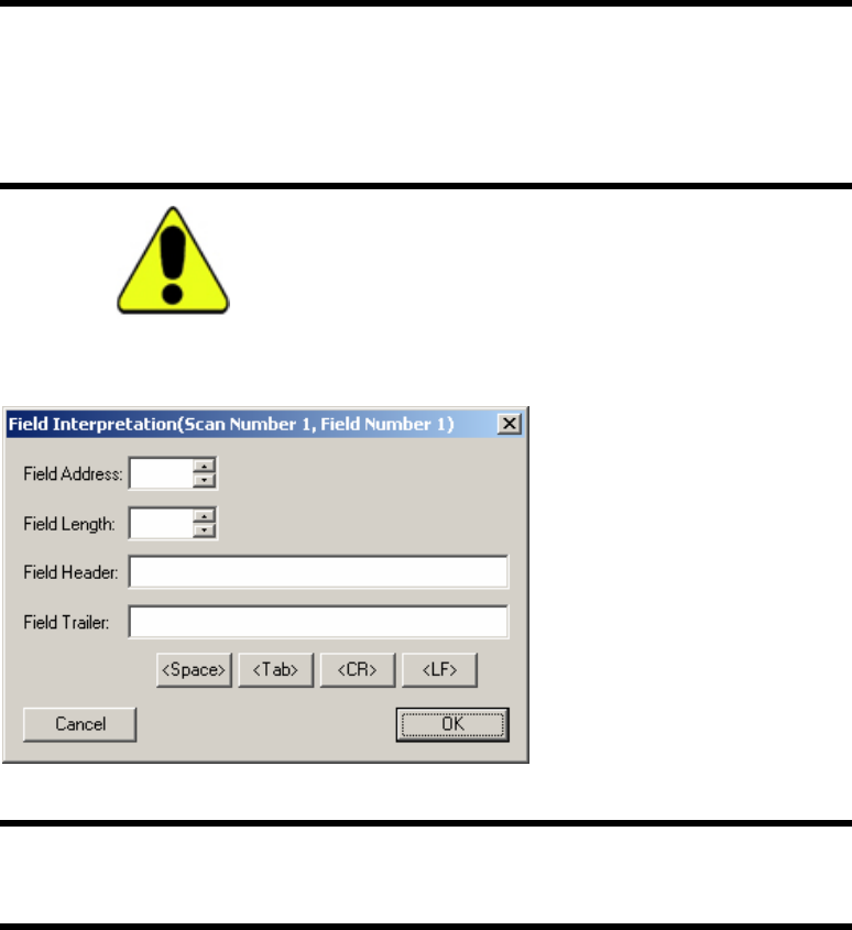
To make an entry in the interpretation field grid or edit an existing entry, double-
click in the desired row and the “Field Interpretation” editing dialog box opens.
Enter the starting address of the field data from the scanned raw data.
EXAMPLE
If an RFID tag is scanned and the RFID tag contains 256 bytes, and the desired data location is at
byte number 10 of the raw data, then enter “10” in the “Field Address”.
Enter the maximum length of the data in “Field Length”. “Field Header”
represents the data that is appended before the raw data prior to transmission to
the host. “Field Trailer” represents the data that is appended after the raw data
prior to transmission to the host.
To append special characters such as “Space”, “Tab”, “Carriage Return”, and
“Line Feed”, use the buttons provided.
The maximum length of field headers and field trailers is 4 characters.
Appendix1 – BaRs Software
Page 37 of 44
Apply To Scanner
The Apply To Scanner button downloads the present configuration settings into
the dual reader. After downloading the configuration settings into the DR1000,
the power must be cycled before the changes take effect.
Read From Scanner
The Read From Scanner button reads the current configuration settings of the
DR1000. Baud Rate and Field Interpretations cannot be read back from the device.
Load From File
The Load From File button loads a previously saved configuration file into the
Scanner Settings dialog box. This feature allows previously saved configuration
settings to be easily applied to one or more devices. The user must explicitly apply
the configuration settings to each desired DR1000 by clicking the “Apply To
Scanner” button.
Save To File
The Save To File button stores the defined Scanner Settings to a file for later
retrieval.
Advanced
The Advanced button enables expanded options available for the DR1000 Dual
Reader. Advanced features include: the ability to set each DR1000 configuration
individually; update firmware; turn LEDs on or off; and sound the DR1000
beeper.
NOTE
The caption of the “Advanced” button will change to
“Normal” when the dialog box is in Advanced mode. Click
the “Normal” button to return to Normal mode.
Appendix1 – BaRs Software
Page 38 of 44
RFF View
RFF View allows the user to load a predefined form to display formatted data.
RFF forms are defined and saved in an XML document and loaded into the BaRS
application. Creating RFF forms is an advanced function beyond the scope of this
document; however, several sample forms are included with the BaRS software.
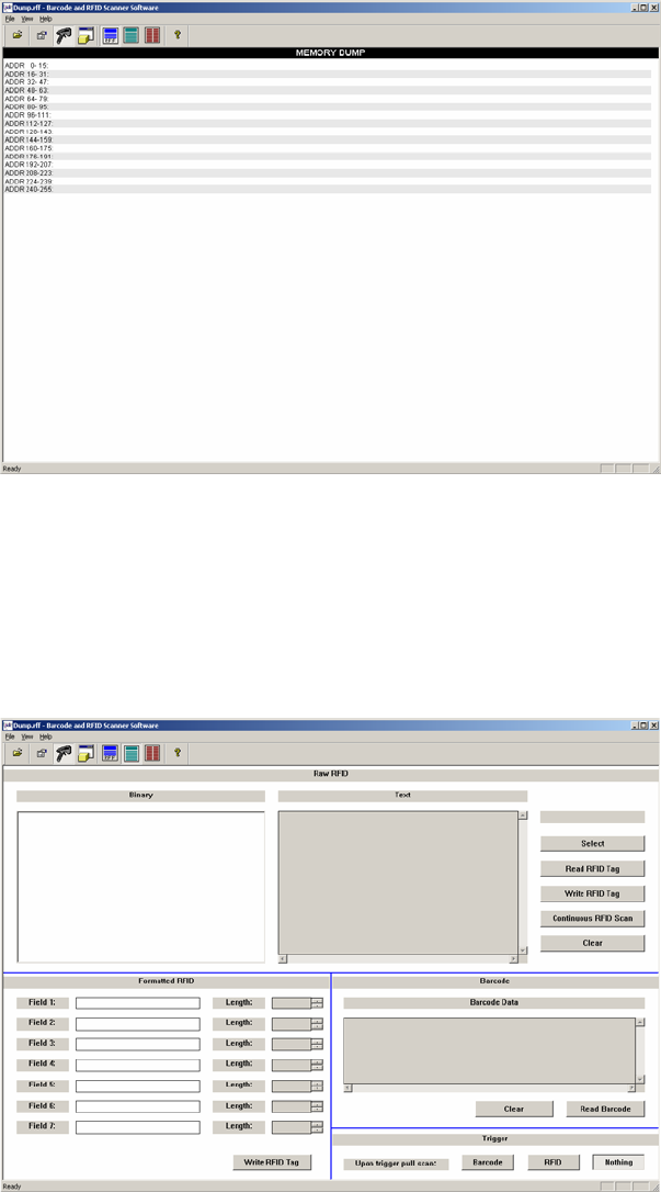
Data View
The Data View is designed to demonstrate the read, write and display capabilities
of the DR1000 Dual Reader.
Appendix1 – BaRs Software
Page 39 of 44
Raw RFID
The Raw RFID section displays the data read from a selected RFID tag, both in
text mode and in binary mode. Click the Select button to read a RFID tag in the
field of the DR1000. After a RFID tag is successfully selected, the UID of the tag
is displayed above the Select button. A RFID tag must be selected before
attempting to read or write to the tag.
• Click the Read RFID Tag button to read and display the data stored to
an RFID tag.
• Click the Write RFID Tag button to write the data that is in the “Binary”
section to a RFID tag.
• Click the Continuous RFID Scan button to set the application in a
continuous scan mode. In this mode, the application continuously
monitors the DR1000 and displays the data of any tag present in the field
of the reader.
• Click the Clear button to clear the “Binary” and “Text” data sections.
Formatted RFID
The Formatted RFID section is designed to write formatted data to a RFID tag.
Seven fields are available, each with a corresponding variable length. Enter the
desired data into one or more of the available fields and define the appropriate
length of each data string. Place a RFID tag within the field of the DR1000 and
click the Write RFID Tag button to write the formatted data.
Note that if the length of the data in each field is smaller than the defined field
length, null characters are added after the data prior to the write. Similarly, if the
length of the data is larger than the corresponding length, the data string is
truncated to the defined length prior to the write.
Barcode
The Barcode section demonstrates reading and displaying data read from a
barcode. Click the Read barcode button to read a barcode. The barcode data is
displayed in the “Barcode Data” window. Click the Clear button to delete the
contents of the “Barcode Data” window.
Trigger Operation
The DR1000 Dual Reader is capable of sending trigger events to the host
computer. These are defined in the “Trigger” section of the Data View window.
The DR1000 can read a barcode upon trigger pull, read a RFID tag upon trigger
pull, or do nothing, depending on the selected operation. A short beep is heard
after the completion of a trigger pull event.
Appendix1 – BaRs Software
Page 40 of 44
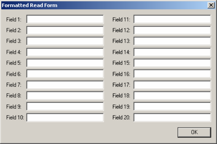
Formatted Read Form
The Formatted Read Form demonstrates the ability of the DR1000 to act as a
keyboard emulation device. Once proper field interpretations are designed for a
particular application, this form may be used to demonstrate how the DR1000 can
populate the fields of the form.
Appendix2 – DR1000 Demonstration
Page 41 of 44
Appendix 2 - DR1000
Demonstration
This demonstration is designed to walk a user step-by-step through the process of
writing and reading data from an RFID tag, and reading data from a barcode. It
demonstrates the field interpretations capability, trigger event detection, and
command mode operation of the DR1000.
Start the Application
Double-click the BaRS icon placed on the Windows desktop, or select the BaRS
option from the Start menu to launch the application.
Preparing the RFID Tag
• Click the Application Settings button to set the desired
parameters for communication with the DR1000 Dual Reader. Set the
serial port to match the appropriate COM port defined in the Device
Manager, and then click OK.
• Click the Start Scanner button to initialize communication with
the DR1000.
• Click the Data View button to open the data view of the
application.
• Enter the following data into the Formatted RFID section of the Data View
window:
(Use the Down arrow buttons to set the lengths)
Field 1: First Name Length: 15
Field 2: Last Name Length: 15
Field 3: 12345 First Street Length: 20
Field 4: New Town Length: 15
Field 5: CA Length: 5
Field 6: 91340 Length: 5
Field 7: (987)654-3210 Length: 15
• Place a RFID tag within 5 inches of the face of the reader and click on the
Write RFID Tag button. The data will be written to the RFID tag as
defined in the Formatted RFID section.
This demonstration
assumes that BaRS
software is installed
on the host computer,
and that serial
emulation drivers, if
using the USB model,
are also installed and
configured properly.
Appendix2 – DR1000 Demonstration
Page 42 of 44
Applying the Scanner Configurations
• Click the Scanner Settings button to open the Scanner Settings
dialog box.
NOTE
If the dual reader settings dialog box does not appear,
navigate to the C:\Program Files\Precision Dynamics
Corporation\BaRS directory and double-click on the
RegisterMSFlsGrd icon. Then try to open the dialog box
again.
• Click the Load From File button, and select the “DEMO1.DRC”
configuration file from the Configuration Files folder.
• Click the Apply To Scanner button to download the configuration
settings to the DR1000.
• Click the Close button to exit the Scanner Settings dialog box.
• Click the Start Scanner button to stop communication with the
reader.
• Exit the BaRS application.
• The power to the DR1000 must be cycled before the new configuration
settings may be applied to the device. Disconnect the DR1000 from its
power source and reconnect for the new settings to take affect.
Keyboard Emulation Read (USB and PS/2 versions)
• Double-click the BaRS icon placed on the Windows desktop, or select the
BaRS option from the Start menu to launch the application.
• Click the Form Dialog button to open the formatted read dialog
box.
• Point the DR1000 at a barcode, pull the trigger, and the “Field 1” data will
be populated.
• Point the DR1000 at the RFID tag programmed previously and pull the
trigger. Fields 2 through 8 will be populated.
The above exercise demonstrated how the DR1000 may be used to emulate
keyboard entry by applying “Field Interpretations” to the data read from both a
barcode and a RFID tag. Close the Formatted Read form and exit the BaRS
application.

Appendix2 – DR1000 Demonstration
Page 43 of 44
Changing the Scanner Configuration (USB version)
• Disconnect the DR1000 from the host computer.
• Pull and hold the trigger and reconnect the device into the computer’s
USB port. Once the device is again connected to the host, release the
trigger. This action causes the DR1000 to register as a serial device with
the computer.
• Start the BaRS application.
• Click the Start Scanner button to initialize communication with
the DR1000.
• Click the Scanner Settings button to open the Scanner Settings
dialog box.
• Click the Read From Scanner button to display the current configuration
settings of the device.
• Select “Serial” from the “USB Mode” drop down list.
• Select “Disable” from the “Scan Sequence” drop down list.
• Select “Pull” from the “Trigger Notification” drop down list.
• Click the Apply To Scanner button.
• Click the Close button to exit the Scanner Settings dialog box.
• Click the Start Scanner button to stop communication with the
reader.
• Disconnect the DR1000 from the computer, and then reconnect without
pulling the trigger.
The new settings are now stored in the device memory and preserved over a
power cycle. Repeat the procedure above if changes to the configuration
settings are desired.

Appendix2 – DR1000 Demonstration
Page 44 of 44
Command Mode Read
The following steps illustrate the various RFID and barcode read events of the
DR1000 if operated in Command (host) mode.
• Start the BaRS application if it is not already running.
• Click the Start Scanner button to initialize communication with
the DR1000.
• Click the Data View button to open the data view of the
application.
• Place an RFID tag in front of the dual reader and click the Read RFID
Tag button. The data from the RFID tag will be read and displayed in the
“Binary”, and “Text” fields of the “Raw RFID” section.
• Click the Continuous RFID Scan button and place an RFID tag in front
of the dual reader. The data from the RFID tag will be read and displayed
in the “Binary”, and “Text” fields of the “Raw RFID” section. Remove
the RFID tag from the field of the reader and the data will clear
automatically.
• Click the Continuous RFID Scan button to end the continuous scan.
• Point the DR1000 at a barcode and click the Read Barcode button. The
barcode data will be displayed in the Barcode Data section of the Data
View window. Click the Clear button to clear the data.
Trigger Events
The following steps illustrate the trigger events of the DR1000 if operated in
Command (host) mode.
• Click the Barcode button in the “Trigger” section.
• Point the DR1000 at a barcode and pull the trigger. The DR1000 will read
a barcode and beep at the end of the operation.
• Click the RFID button in the “Trigger” section.
• Place an RFID tag in front of the dual reader and pull the trigger. The
DR1000 will read the data of the RFID tag and beep at the end of the
operation.
• Click the Nothing button in the “Trigger” section.
• Pull the trigger and the DR1000 will beep without scanning anything.
• This demonstrates the trigger event and Command (host) mode
capabilities of the dual reader.