JADAK a business unit of Novanta MERCURY5E RFID Module User Manual MercuryEmbedMods UserGuide
Trimble Navigation Limited RFID Module MercuryEmbedMods UserGuide
Contents
- 1. Manual
- 2. User man.
Manual

Mercury®5e-Class Embedded Modules
User Guide

Mercury5e-Class Embedded Modules
User Guide

Government Limited Rights Notice: All documentation and manuals were developed at
private expense and no part of it was developed using Government funds.
The U.S. Government’s rights to use, modify, reproduce, release, perform, display, or disclose the
technical data contained herein are restricted by paragraph (b)(3) of the Rights in Technical
Data — Noncommercial Items clause (DFARS 252.227-7013(b)(3)), as amended from time-to-
time. Any reproduction of technical data or portions thereof marked with this legend must also
reporduce the markings. Any person, other than the U.S. Government, who has been provided
access to such data must promptly notify ThingMagic, Inc.
ThingMagic, Mercury, and the ThingMagic logo are trademarks or registered trademarks of
ThingMagic, Inc.
Other product names mentioned herein may be trademarks or registered trademarks of
ThingMagic, Inc. or other companies.
© Copyright 2000–2008 ThingMagic, Inc. All Rights Reserved
ThingMagic, Inc.
One Broadway, 5th floor
Cambridge, MA 02142
866-833-4069
Third Edition
March, 2008

Communication Regulation Information
Communication Regulation Information
EMC FCC 47 CFR, Part 15
Industrie Canada RSS-210
Federal Communication Commission Interference Statement
This equipment has been tested and found to comply with the limits for a Class B
digital device, pursuant to Part 15 of the FCC Rules. These limits are designed to provide
reasonable protection against harmful interference in a residential installation. This equipment
generates uses and can radiate radio frequency energy and, if not installed and used in
accordance with the instructions, may cause harmful interference to radio communications.
However, there is no guarantee that interference will not occur in a particular installation. If this
equipment does cause harmful interference to radio or television reception, which can be
determined by turning the equipment off and on, the user is encouraged to try to correct the
interference by one of the following measures:
Reorient or relocate the receiving antenna.
Increase the separation between the equipment and receiver.
Connect the equipment into an outlet on a circuit different from that to which the receiver
is connected.
Consult the dealer or an experienced radio/TV technician for help.
This device complies with Part 15 of the FCC Rules. Operation is subject to the following two
conditions: (1) This device may not cause harmful interference, and (2) this device must accept
any interference received, including interference that may cause undesired operation.
FCC Caution: Any changes or modifications not expressly approved by the party responsible
for compliance could void the user's authority to operate this equipment.
This transmitter module is authorized to be used in other devices only by OEM
integrators under the following conditions:
1. The antenna(s) must be installed such that a minimum separation distance of 20cm is
maintained between the radiator (antenna) & user’s/nearby people’s body at all times.
2. The transmitter module must not be co-located with any other antenna or transmitter.
As long as the two conditions above are met, further transmitter testing will not be required.
However, the OEM integrator is still responsible for testing their end-product for any additional
compliance requirements required with this module installed (for example, digital device
emissions, PC peripheral requirements, etc.).

Communication Regulation Information
Note
In the event that these conditions can not be met (for certain configurations or co-
location with another transmitter), then the FCC authorization is no longer
considered valid and the FCC ID can not be used on the final product. In these
circumstances, the OEM integrator will be responsible for re-evaluating the end
product (including the transmitter) and obtaining a separate FCC authorization.
The OEM integrator has to be aware not to provide information to the end user regarding how
to install or remove this RF module in the user manual of the end product.
User Manual Requirement
The user manual for the end product must include the following information in a prominent
location;
“To comply with FCC’s RF radiation exposure requirements, the antenna(s) used for this
transmitter must be installed such that a minimum separation distance of 20cm is maintained
between the radiator (antenna) & user’s/nearby people’s body at all times and must not be co-
located or operating in conjunction with any other antenna or transmitter.”
End Product Labeling
The final end product must be labeled in a visible area with the following:
“Contains Transmitter Module FCC ID: QV5MERCURY5E”
or
“Contains FCC ID: QV5MERCURY5E.”
(Replace QV5MERCURY5E, for the Mercury5e, with QV5MERCURY5EC for the M5e-
Compact).
Industry Canada
Operation is subject to the following two conditions: (1) this device may not cause interference,
and (2) this device must accept any interference, including interference that may cause
undesired operation of the device.
To reduce potential radio interference to other users, the antenna type and its gain should be so
chosen that the equivalent isotropically radiated power (e.i.r.p.) is not more than that permitted
for successful communication.

Communication Regulation Information
This device has been designed to operate with the antennas listed in Authorized Antennas.
Antennas not included in this list are strictly prohibited for use with this device.
To comply with IC RF exposure limits for general population/uncontrolled exposure, the
antenna(s) used for this transmitter must be installed to provide a separation distance of at
least 20 cm from all persons and must not be collocated or operating in conjunction with any
other antenna or transmitter.

1
Contents
Communication Regulation Information . . . . . . . . . . . . . . . . . . . . . . . . . . . . . . . . . . . . . . . . . . . . . . . . . . . . . . . .i
Federal Communication Commission Interference Statement . . . . . . . . . . . . . . . . . . . . . . . . . . . . . . . . . . . i
User Manual Requirement . . . . . . . . . . . . . . . . . . . . . . . . . . . . . . . . . . . . . . . . . . . . . . . . . . . . . . . . . . .ii
End Product Labeling. . . . . . . . . . . . . . . . . . . . . . . . . . . . . . . . . . . . . . . . . . . . . . . . . . . . . . . . . . . . . . .ii
Industry Canada . . . . . . . . . . . . . . . . . . . . . . . . . . . . . . . . . . . . . . . . . . . . . . . . . . . . . . . . . . . . . . . . . . . . . . . .ii
Chapter 1: Introducing the Mercury Embedded Reader . . . . . . . . . . . . . . . . . . . . . . . . .1
About the Readers . . . . . . . . . . . . . . . . . . . . . . . . . . . . . . . . . . . . . . . . . . . . . . . . . . . . . . . . . . . . . . . . . . . . . . . . . . . 1
Product Line Overview . . . . . . . . . . . . . . . . . . . . . . . . . . . . . . . . . . . . . . . . . . . . . . . . . . . . . . . . . . . . . . . . . . . . . . . 2
Software for the Reader . . . . . . . . . . . . . . . . . . . . . . . . . . . . . . . . . . . . . . . . . . . . . . . . . . . . . . . . . . . . . . . . . . . . . . 2
Boot Loader. . . . . . . . . . . . . . . . . . . . . . . . . . . . . . . . . . . . . . . . . . . . . . . . . . . . . . . . . . . . . . . . . . . . . . . . . . . 3
Application Firmware . . . . . . . . . . . . . . . . . . . . . . . . . . . . . . . . . . . . . . . . . . . . . . . . . . . . . . . . . . . . . . . . . . . 3
About the Reader Assistant . . . . . . . . . . . . . . . . . . . . . . . . . . . . . . . . . . . . . . . . . . . . . . . . . . . . . . . . . . . 3
Chapter 2: Setting Up the Reader . . . . . . . . . . . . . . . . . . . . . . . . . . . . . . . . . . . . . . . . . . . . .4
Attaching the Antenna . . . . . . . . . . . . . . . . . . . . . . . . . . . . . . . . . . . . . . . . . . . . . . . . . . . . . . . . . . . . . . . . . . . . . . . 4
Powering Up the Reader . . . . . . . . . . . . . . . . . . . . . . . . . . . . . . . . . . . . . . . . . . . . . . . . . . . . . . . . . . . . . . . . . . . . . 6
Chapter 3: Using the Reader Assistant . . . . . . . . . . . . . . . . . . . . . . . . . . . . . . . . . . . . . . . .8
Starting the Reader Assistant . . . . . . . . . . . . . . . . . . . . . . . . . . . . . . . . . . . . . . . . . . . . . . . . . . . . . . . . . . . . . . . . . 9
Communication Settings . . . . . . . . . . . . . . . . . . . . . . . . . . . . . . . . . . . . . . . . . . . . . . . . . . . . . . . . . . . . . . . . . . . . 10
Serial Communications Problem . . . . . . . . . . . . . . . . . . . . . . . . . . . . . . . . . . . . . . . . . . . . . . . . . . . . . . . . . 11
Menu Commands . . . . . . . . . . . . . . . . . . . . . . . . . . . . . . . . . . . . . . . . . . . . . . . . . . . . . . . . . . . . . . . . . . . . . . . . . . . 12
File menu . . . . . . . . . . . . . . . . . . . . . . . . . . . . . . . . . . . . . . . . . . . . . . . . . . . . . . . . . . . . . . . . . . . . . . . . . . . . 12
Options menu . . . . . . . . . . . . . . . . . . . . . . . . . . . . . . . . . . . . . . . . . . . . . . . . . . . . . . . . . . . . . . . . . . . . . . . . 12
Action menu. . . . . . . . . . . . . . . . . . . . . . . . . . . . . . . . . . . . . . . . . . . . . . . . . . . . . . . . . . . . . . . . . . . . . . . . . . 12
Configuring the Reader . . . . . . . . . . . . . . . . . . . . . . . . . . . . . . . . . . . . . . . . . . . . . . . . . . . . . . . . . . . . . . . . . . . . .13
Reading and Writing to Tags . . . . . . . . . . . . . . . . . . . . . . . . . . . . . . . . . . . . . . . . . . . . . . . . . . . . . . . . . . . . . . . . .16
Advanced Settings . . . . . . . . . . . . . . . . . . . . . . . . . . . . . . . . . . . . . . . . . . . . . . . . . . . . . . . . . . . . . . . . . . . . 18
Serial Log . . . . . . . . . . . . . . . . . . . . . . . . . . . . . . . . . . . . . . . . . . . . . . . . . . . . . . . . . . . . . . . . . . . . . . . . . . . . . . . . . .20

2
Loading FW and Using the Flash Area . . . . . . . . . . . . . . . . . . . . . . . . . . . . . . . . . . . . . . . . . . . . . . . . . . . . . . . . 21
Working with Tags . . . . . . . . . . . . . . . . . . . . . . . . . . . . . . . . . . . . . . . . . . . . . . . . . . . . . . . . . . . . . . . . . . . . . . . . . . 24
Tag Operations Tab . . . . . . . . . . . . . . . . . . . . . . . . . . . . . . . . . . . . . . . . . . . . . . . . . . . . . . . . . . . . . . . . . . . 24
Write Tag ID. . . . . . . . . . . . . . . . . . . . . . . . . . . . . . . . . . . . . . . . . . . . . . . . . . . . . . . . . . . . . . . . . . . . . . . 28
Reading Tag Data . . . . . . . . . . . . . . . . . . . . . . . . . . . . . . . . . . . . . . . . . . . . . . . . . . . . . . . . . . . . . . . . . . 29
Writing Tag Data . . . . . . . . . . . . . . . . . . . . . . . . . . . . . . . . . . . . . . . . . . . . . . . . . . . . . . . . . . . . . . . . . . . 29
Killing Tags. . . . . . . . . . . . . . . . . . . . . . . . . . . . . . . . . . . . . . . . . . . . . . . . . . . . . . . . . . . . . . . . . . . . . . . . 30
Locking Tags . . . . . . . . . . . . . . . . . . . . . . . . . . . . . . . . . . . . . . . . . . . . . . . . . . . . . . . . . . . . . . . . . . . . . . 31
Reading Tags. . . . . . . . . . . . . . . . . . . . . . . . . . . . . . . . . . . . . . . . . . . . . . . . . . . . . . . . . . . . . . . . . . . . . . 32
Debugging the Module . . . . . . . . . . . . . . . . . . . . . . . . . . . . . . . . . . . . . . . . . . . . . . . . . . . . . . . . . . . . . . . . . . . . . .33
Appendix A: Hardware Details . . . . . . . . . . . . . . . . . . . . . . . . . . . . . . . . . . . . . . . . . . . . .1-39
Mechanicals . . . . . . . . . . . . . . . . . . . . . . . . . . . . . . . . . . . . . . . . . . . . . . . . . . . . . . . . . . . . . . . . . . . . . . . . . . . . . . . . 39
Antenna Connector. . . . . . . . . . . . . . . . . . . . . . . . . . . . . . . . . . . . . . . . . . . . . . . . . . . . . . . . . . . . . . . . . . . . 41
Communications Connector . . . . . . . . . . . . . . . . . . . . . . . . . . . . . . . . . . . . . . . . . . . . . . . . . . . . . . . . . . . . 41
Appendix B: Error Messages . . . . . . . . . . . . . . . . . . . . . . . . . . . . . . . . . . . . . . . . . . . . . .1-45
Common Error Messages . . . . . . . . . . . . . . . . . . . . . . . . . . . . . . . . . . . . . . . . . . . . . . . . . . . . . . . . . . . . . . . . . . .45
FAULT_MSG_WRONG_NUMBER_OF_DATA – (100h). . . . . . . . . . . . . . . . . . . . . . . . . . . . . . . . . . . . . 45
Cause . . . . . . . . . . . . . . . . . . . . . . . . . . . . . . . . . . . . . . . . . . . . . . . . . . . . . . . . . . . . . . . . . . . . . . . . . . . . 45
Solution . . . . . . . . . . . . . . . . . . . . . . . . . . . . . . . . . . . . . . . . . . . . . . . . . . . . . . . . . . . . . . . . . . . . . . . . . . 45
FAULT_INVALID_OPCODE – (101h) . . . . . . . . . . . . . . . . . . . . . . . . . . . . . . . . . . . . . . . . . . . . . . . . . . . . 46
Cause . . . . . . . . . . . . . . . . . . . . . . . . . . . . . . . . . . . . . . . . . . . . . . . . . . . . . . . . . . . . . . . . . . . . . . . . . . . . 46
Solution . . . . . . . . . . . . . . . . . . . . . . . . . . . . . . . . . . . . . . . . . . . . . . . . . . . . . . . . . . . . . . . . . . . . . . . . . . 46
FAULT_UNIMPLEMENTED_OPCODE – 102h. . . . . . . . . . . . . . . . . . . . . . . . . . . . . . . . . . . . . . . . . . . . . 46
Cause . . . . . . . . . . . . . . . . . . . . . . . . . . . . . . . . . . . . . . . . . . . . . . . . . . . . . . . . . . . . . . . . . . . . . . . . . . . . 46
Solution . . . . . . . . . . . . . . . . . . . . . . . . . . . . . . . . . . . . . . . . . . . . . . . . . . . . . . . . . . . . . . . . . . . . . . . . . . 46
FAULT_MSG_POWER_TOO_HIGH – 103h . . . . . . . . . . . . . . . . . . . . . . . . . . . . . . . . . . . . . . . . . . . . . . 46
Cause . . . . . . . . . . . . . . . . . . . . . . . . . . . . . . . . . . . . . . . . . . . . . . . . . . . . . . . . . . . . . . . . . . . . . . . . . . . . 46
Solution . . . . . . . . . . . . . . . . . . . . . . . . . . . . . . . . . . . . . . . . . . . . . . . . . . . . . . . . . . . . . . . . . . . . . . . . . . 46
FAULT_MSG_INVALID_FREQ_RECEIVED (104h) . . . . . . . . . . . . . . . . . . . . . . . . . . . . . . . . . . . . . . . . . 47
Cause . . . . . . . . . . . . . . . . . . . . . . . . . . . . . . . . . . . . . . . . . . . . . . . . . . . . . . . . . . . . . . . . . . . . . . . . . . . . 47
Solution . . . . . . . . . . . . . . . . . . . . . . . . . . . . . . . . . . . . . . . . . . . . . . . . . . . . . . . . . . . . . . . . . . . . . . . . . . 47
FAULT_MSG_INVALID_PARAMETER_VALUE - (105h) . . . . . . . . . . . . . . . . . . . . . . . . . . . . . . . . . . . . . 47
Cause . . . . . . . . . . . . . . . . . . . . . . . . . . . . . . . . . . . . . . . . . . . . . . . . . . . . . . . . . . . . . . . . . . . . . . . . . . . . 47
Solution . . . . . . . . . . . . . . . . . . . . . . . . . . . . . . . . . . . . . . . . . . . . . . . . . . . . . . . . . . . . . . . . . . . . . . . . . . 47
FAULT_MSG_POWER_TOO_LOW - (106h) . . . . . . . . . . . . . . . . . . . . . . . . . . . . . . . . . . . . . . . . . . . . . . 47
Cause . . . . . . . . . . . . . . . . . . . . . . . . . . . . . . . . . . . . . . . . . . . . . . . . . . . . . . . . . . . . . . . . . . . . . . . . . . . . 47
Solution . . . . . . . . . . . . . . . . . . . . . . . . . . . . . . . . . . . . . . . . . . . . . . . . . . . . . . . . . . . . . . . . . . . . . . . . . . 47

3
FAULT_UNIMPLEMENTED_FEATURE - (109h) . . . . . . . . . . . . . . . . . . . . . . . . . . . . . . . . . . . . . . . . . . . . 48
Cause . . . . . . . . . . . . . . . . . . . . . . . . . . . . . . . . . . . . . . . . . . . . . . . . . . . . . . . . . . . . . . . . . . . . . . . . . . . . 48
Solution . . . . . . . . . . . . . . . . . . . . . . . . . . . . . . . . . . . . . . . . . . . . . . . . . . . . . . . . . . . . . . . . . . . . . . . . . . 48
FAULT_INVALID_BAUD_RATE - (10Ah) . . . . . . . . . . . . . . . . . . . . . . . . . . . . . . . . . . . . . . . . . . . . . . . . . . 48
Cause . . . . . . . . . . . . . . . . . . . . . . . . . . . . . . . . . . . . . . . . . . . . . . . . . . . . . . . . . . . . . . . . . . . . . . . . . . . . 48
Solution . . . . . . . . . . . . . . . . . . . . . . . . . . . . . . . . . . . . . . . . . . . . . . . . . . . . . . . . . . . . . . . . . . . . . . . . . . 48
Bootloader Faults. . . . . . . . . . . . . . . . . . . . . . . . . . . . . . . . . . . . . . . . . . . . . . . . . . . . . . . . . . . . . . . . . . . . . . . . . . . 49
FAULT_BL_INVALID_IMAGE_CRC – 200h . . . . . . . . . . . . . . . . . . . . . . . . . . . . . . . . . . . . . . . . . . . . . . . 49
Cause . . . . . . . . . . . . . . . . . . . . . . . . . . . . . . . . . . . . . . . . . . . . . . . . . . . . . . . . . . . . . . . . . . . . . . . . . . . . 49
Solution . . . . . . . . . . . . . . . . . . . . . . . . . . . . . . . . . . . . . . . . . . . . . . . . . . . . . . . . . . . . . . . . . . . . . . . . . . 49
FAULT_BL_INVALID_APP_END_ADDR – 201h. . . . . . . . . . . . . . . . . . . . . . . . . . . . . . . . . . . . . . . . . . . . 49
Cause . . . . . . . . . . . . . . . . . . . . . . . . . . . . . . . . . . . . . . . . . . . . . . . . . . . . . . . . . . . . . . . . . . . . . . . . . . . . 49
Solution . . . . . . . . . . . . . . . . . . . . . . . . . . . . . . . . . . . . . . . . . . . . . . . . . . . . . . . . . . . . . . . . . . . . . . . . . . 49
Flash Faults . . . . . . . . . . . . . . . . . . . . . . . . . . . . . . . . . . . . . . . . . . . . . . . . . . . . . . . . . . . . . . . . . . . . . . . . . . . . . . . . 50
FAULT_FLASH_BAD_ERASE_PASSWORD – 300h . . . . . . . . . . . . . . . . . . . . . . . . . . . . . . . . . . . . . . . 50
Cause . . . . . . . . . . . . . . . . . . . . . . . . . . . . . . . . . . . . . . . . . . . . . . . . . . . . . . . . . . . . . . . . . . . . . . . . . . . . 50
Solution . . . . . . . . . . . . . . . . . . . . . . . . . . . . . . . . . . . . . . . . . . . . . . . . . . . . . . . . . . . . . . . . . . . . . . . . . . 50
FAULT_FLASH_BAD_WRITE_PASSWORD – 301h . . . . . . . . . . . . . . . . . . . . . . . . . . . . . . . . . . . . . . . 50
Cause . . . . . . . . . . . . . . . . . . . . . . . . . . . . . . . . . . . . . . . . . . . . . . . . . . . . . . . . . . . . . . . . . . . . . . . . . . . . 50
Solution . . . . . . . . . . . . . . . . . . . . . . . . . . . . . . . . . . . . . . . . . . . . . . . . . . . . . . . . . . . . . . . . . . . . . . . . . . 50
FAULT_FLASH_UNDEFINED_ERROR – 302h. . . . . . . . . . . . . . . . . . . . . . . . . . . . . . . . . . . . . . . . . . . . . 51
Cause . . . . . . . . . . . . . . . . . . . . . . . . . . . . . . . . . . . . . . . . . . . . . . . . . . . . . . . . . . . . . . . . . . . . . . . . . . . . 51
Solution . . . . . . . . . . . . . . . . . . . . . . . . . . . . . . . . . . . . . . . . . . . . . . . . . . . . . . . . . . . . . . . . . . . . . . . . . . 51
FAULT_FLASH_ILLEGAL_SECTOR – 303h. . . . . . . . . . . . . . . . . . . . . . . . . . . . . . . . . . . . . . . . . . . . . . . 51
Cause . . . . . . . . . . . . . . . . . . . . . . . . . . . . . . . . . . . . . . . . . . . . . . . . . . . . . . . . . . . . . . . . . . . . . . . . . . . . 51
Solution . . . . . . . . . . . . . . . . . . . . . . . . . . . . . . . . . . . . . . . . . . . . . . . . . . . . . . . . . . . . . . . . . . . . . . . . . . 51
FAULT_FLASH_WRITE_TO_NON_ERASED_AREA – 304h . . . . . . . . . . . . . . . . . . . . . . . . . . . . . . . . . 51
Cause . . . . . . . . . . . . . . . . . . . . . . . . . . . . . . . . . . . . . . . . . . . . . . . . . . . . . . . . . . . . . . . . . . . . . . . . . . . . 51
Solution . . . . . . . . . . . . . . . . . . . . . . . . . . . . . . . . . . . . . . . . . . . . . . . . . . . . . . . . . . . . . . . . . . . . . . . . . . 51
FAULT_FLASH_WRITE_TO_ILLEGAL_SECTOR – 305h . . . . . . . . . . . . . . . . . . . . . . . . . . . . . . . . . . . . 51
Cause . . . . . . . . . . . . . . . . . . . . . . . . . . . . . . . . . . . . . . . . . . . . . . . . . . . . . . . . . . . . . . . . . . . . . . . . . . . . 51
Solution . . . . . . . . . . . . . . . . . . . . . . . . . . . . . . . . . . . . . . . . . . . . . . . . . . . . . . . . . . . . . . . . . . . . . . . . . . 52
FAULT_FLASH_VERIFY_FAILED – 306h . . . . . . . . . . . . . . . . . . . . . . . . . . . . . . . . . . . . . . . . . . . . . . . . . 52
Cause . . . . . . . . . . . . . . . . . . . . . . . . . . . . . . . . . . . . . . . . . . . . . . . . . . . . . . . . . . . . . . . . . . . . . . . . . . . . 52
Solution . . . . . . . . . . . . . . . . . . . . . . . . . . . . . . . . . . . . . . . . . . . . . . . . . . . . . . . . . . . . . . . . . . . . . . . . . . 52
Protocol Faults . . . . . . . . . . . . . . . . . . . . . . . . . . . . . . . . . . . . . . . . . . . . . . . . . . . . . . . . . . . . . . . . . . . . . . . . . . . . .53
FAULT_NO_TAGS_FOUND – (400h) . . . . . . . . . . . . . . . . . . . . . . . . . . . . . . . . . . . . . . . . . . . . . . . . . . . . 53
Cause . . . . . . . . . . . . . . . . . . . . . . . . . . . . . . . . . . . . . . . . . . . . . . . . . . . . . . . . . . . . . . . . . . . . . . . . . . . . 53
Solution . . . . . . . . . . . . . . . . . . . . . . . . . . . . . . . . . . . . . . . . . . . . . . . . . . . . . . . . . . . . . . . . . . . . . . . . . . 54
FAULT_NO_PROTOCOL_DEFINED – 401h . . . . . . . . . . . . . . . . . . . . . . . . . . . . . . . . . . . . . . . . . . . . . . 54

4
Cause . . . . . . . . . . . . . . . . . . . . . . . . . . . . . . . . . . . . . . . . . . . . . . . . . . . . . . . . . . . . . . . . . . . . . . . . . . . . 54
Solution . . . . . . . . . . . . . . . . . . . . . . . . . . . . . . . . . . . . . . . . . . . . . . . . . . . . . . . . . . . . . . . . . . . . . . . . . . 54
FAULT_INVALID_PROTOCOL_SPECIFIED – 402h . . . . . . . . . . . . . . . . . . . . . . . . . . . . . . . . . . . . . . . . 54
Cause . . . . . . . . . . . . . . . . . . . . . . . . . . . . . . . . . . . . . . . . . . . . . . . . . . . . . . . . . . . . . . . . . . . . . . . . . . . . 54
Solution . . . . . . . . . . . . . . . . . . . . . . . . . . . . . . . . . . . . . . . . . . . . . . . . . . . . . . . . . . . . . . . . . . . . . . . . . . 54
FAULT_WRITE_PASSED_LOCK_FAILED – 403h. . . . . . . . . . . . . . . . . . . . . . . . . . . . . . . . . . . . . . . . . . 55
Cause . . . . . . . . . . . . . . . . . . . . . . . . . . . . . . . . . . . . . . . . . . . . . . . . . . . . . . . . . . . . . . . . . . . . . . . . . . . . 55
Solution . . . . . . . . . . . . . . . . . . . . . . . . . . . . . . . . . . . . . . . . . . . . . . . . . . . . . . . . . . . . . . . . . . . . . . . . . . 55
FAULT_PROTOCOL_NO_DATA_READ – 404h . . . . . . . . . . . . . . . . . . . . . . . . . . . . . . . . . . . . . . . . . . . 55
Cause . . . . . . . . . . . . . . . . . . . . . . . . . . . . . . . . . . . . . . . . . . . . . . . . . . . . . . . . . . . . . . . . . . . . . . . . . . . . 55
Solution . . . . . . . . . . . . . . . . . . . . . . . . . . . . . . . . . . . . . . . . . . . . . . . . . . . . . . . . . . . . . . . . . . . . . . . . . . 55
FAULT_AFE_NOT_ON – 405h . . . . . . . . . . . . . . . . . . . . . . . . . . . . . . . . . . . . . . . . . . . . . . . . . . . . . . . . . . 55
Cause . . . . . . . . . . . . . . . . . . . . . . . . . . . . . . . . . . . . . . . . . . . . . . . . . . . . . . . . . . . . . . . . . . . . . . . . . . . . 55
Solution . . . . . . . . . . . . . . . . . . . . . . . . . . . . . . . . . . . . . . . . . . . . . . . . . . . . . . . . . . . . . . . . . . . . . . . . . . 55
FAULT_PROTOCOL_WRITE_FAILED – 406h . . . . . . . . . . . . . . . . . . . . . . . . . . . . . . . . . . . . . . . . . . . . . 55
Cause . . . . . . . . . . . . . . . . . . . . . . . . . . . . . . . . . . . . . . . . . . . . . . . . . . . . . . . . . . . . . . . . . . . . . . . . . . . . 55
Solution . . . . . . . . . . . . . . . . . . . . . . . . . . . . . . . . . . . . . . . . . . . . . . . . . . . . . . . . . . . . . . . . . . . . . . . . . . 56
FAULT_NOT_IMPLEMENTED_FOR_THIS_PROTOCOL – 407h . . . . . . . . . . . . . . . . . . . . . . . . . . . . . 56
Cause . . . . . . . . . . . . . . . . . . . . . . . . . . . . . . . . . . . . . . . . . . . . . . . . . . . . . . . . . . . . . . . . . . . . . . . . . . . . 56
Solution . . . . . . . . . . . . . . . . . . . . . . . . . . . . . . . . . . . . . . . . . . . . . . . . . . . . . . . . . . . . . . . . . . . . . . . . . . 56
FAULT_PROTOCOL_INVALID_WRITE_DATA – 408h . . . . . . . . . . . . . . . . . . . . . . . . . . . . . . . . . . . . . . 56
Cause . . . . . . . . . . . . . . . . . . . . . . . . . . . . . . . . . . . . . . . . . . . . . . . . . . . . . . . . . . . . . . . . . . . . . . . . . . . . 56
Solution . . . . . . . . . . . . . . . . . . . . . . . . . . . . . . . . . . . . . . . . . . . . . . . . . . . . . . . . . . . . . . . . . . . . . . . . . . 56
FAULT_PROTOCOL_INVALID_ADDRESS – 409h . . . . . . . . . . . . . . . . . . . . . . . . . . . . . . . . . . . . . . . . . 56
Cause . . . . . . . . . . . . . . . . . . . . . . . . . . . . . . . . . . . . . . . . . . . . . . . . . . . . . . . . . . . . . . . . . . . . . . . . . . . . 56
Solution . . . . . . . . . . . . . . . . . . . . . . . . . . . . . . . . . . . . . . . . . . . . . . . . . . . . . . . . . . . . . . . . . . . . . . . . . . 56
FAULT_GENERAL_TAG_ERROR – 40Ah . . . . . . . . . . . . . . . . . . . . . . . . . . . . . . . . . . . . . . . . . . . . . . . . 57
Cause . . . . . . . . . . . . . . . . . . . . . . . . . . . . . . . . . . . . . . . . . . . . . . . . . . . . . . . . . . . . . . . . . . . . . . . . . . . . 57
Solution . . . . . . . . . . . . . . . . . . . . . . . . . . . . . . . . . . . . . . . . . . . . . . . . . . . . . . . . . . . . . . . . . . . . . . . . . . 57
FAULT_DATA_TOO_LARGE – 40Bh . . . . . . . . . . . . . . . . . . . . . . . . . . . . . . . . . . . . . . . . . . . . . . . . . . . . 57
Cause . . . . . . . . . . . . . . . . . . . . . . . . . . . . . . . . . . . . . . . . . . . . . . . . . . . . . . . . . . . . . . . . . . . . . . . . . . . . 57
Solution . . . . . . . . . . . . . . . . . . . . . . . . . . . . . . . . . . . . . . . . . . . . . . . . . . . . . . . . . . . . . . . . . . . . . . . . . . 57
FAULT_PROTOCOL_INVALID_KILL_PASSWORD – 40Ch . . . . . . . . . . . . . . . . . . . . . . . . . . . . . . . . . 57
Cause . . . . . . . . . . . . . . . . . . . . . . . . . . . . . . . . . . . . . . . . . . . . . . . . . . . . . . . . . . . . . . . . . . . . . . . . . . . . 57
Solution . . . . . . . . . . . . . . . . . . . . . . . . . . . . . . . . . . . . . . . . . . . . . . . . . . . . . . . . . . . . . . . . . . . . . . . . . . 57
FAULT_PROTOCOL_KILL_FAILED - 40Eh. . . . . . . . . . . . . . . . . . . . . . . . . . . . . . . . . . . . . . . . . . . . . . . . 57
Cause . . . . . . . . . . . . . . . . . . . . . . . . . . . . . . . . . . . . . . . . . . . . . . . . . . . . . . . . . . . . . . . . . . . . . . . . . . . . 57
Solution . . . . . . . . . . . . . . . . . . . . . . . . . . . . . . . . . . . . . . . . . . . . . . . . . . . . . . . . . . . . . . . . . . . . . . . . . . 58
FAULT_GEN2 PROTOCOL_OTHER_ERROR - 420h. . . . . . . . . . . . . . . . . . . . . . . . . . . . . . . . . . . . . . . 58
FAULT_GEN2_PROTOCOL_MEMORY_OVERRUN_BAD_PC - 423h. . . . . . . . . . . . . . . . . . . . . . . . . 58
FAULT_GEN2 PROTOCOL_MEMORY_LOCKED - 424h . . . . . . . . . . . . . . . . . . . . . . . . . . . . . . . . . . . 58

5
FAULT_GEN2 PROTOCOL_INSUFFICIENT_POWER - 42Bh. . . . . . . . . . . . . . . . . . . . . . . . . . . . . . . . 58
FAULT_GEN2 PROTOCOL_NON_SPECIFIC_ERROR - 42Fh . . . . . . . . . . . . . . . . . . . . . . . . . . . . . . . 58
FAULT_GEN2 PROTOCOL_UNKNOWN_ERROR - 430h. . . . . . . . . . . . . . . . . . . . . . . . . . . . . . . . . . . 58
Analog Hardware Abstraction Layer Faults. . . . . . . . . . . . . . . . . . . . . . . . . . . . . . . . . . . . . . . . . . . . . . . . . . . . 59
FAULT_AHAL_INVALID_FREQ – 500h . . . . . . . . . . . . . . . . . . . . . . . . . . . . . . . . . . . . . . . . . . . . . . . . . . . 59
Cause . . . . . . . . . . . . . . . . . . . . . . . . . . . . . . . . . . . . . . . . . . . . . . . . . . . . . . . . . . . . . . . . . . . . . . . . . . . . 59
Solution . . . . . . . . . . . . . . . . . . . . . . . . . . . . . . . . . . . . . . . . . . . . . . . . . . . . . . . . . . . . . . . . . . . . . . . . . . 59
FAULT_AHAL_INVALID_FREQ – 501h . . . . . . . . . . . . . . . . . . . . . . . . . . . . . . . . . . . . . . . . . . . . . . . . . . . 59
Cause . . . . . . . . . . . . . . . . . . . . . . . . . . . . . . . . . . . . . . . . . . . . . . . . . . . . . . . . . . . . . . . . . . . . . . . . . . . . 59
Solution . . . . . . . . . . . . . . . . . . . . . . . . . . . . . . . . . . . . . . . . . . . . . . . . . . . . . . . . . . . . . . . . . . . . . . . . . . 59
Tag ID Buffer Faults . . . . . . . . . . . . . . . . . . . . . . . . . . . . . . . . . . . . . . . . . . . . . . . . . . . . . . . . . . . . . . . . . . . . . . . .60
FAULT_TAG_ID_BUFFER_NOT_ENOUGH_TAGS_AVAILABLE – 600h . . . . . . . . . . . . . . . . . . . . . . . 60
Cause . . . . . . . . . . . . . . . . . . . . . . . . . . . . . . . . . . . . . . . . . . . . . . . . . . . . . . . . . . . . . . . . . . . . . . . . . . . . 60
Solution . . . . . . . . . . . . . . . . . . . . . . . . . . . . . . . . . . . . . . . . . . . . . . . . . . . . . . . . . . . . . . . . . . . . . . . . . . 60
FAULT_TAG_ID_BUFFER_FULL – 601h. . . . . . . . . . . . . . . . . . . . . . . . . . . . . . . . . . . . . . . . . . . . . . . . . . 60
Cause . . . . . . . . . . . . . . . . . . . . . . . . . . . . . . . . . . . . . . . . . . . . . . . . . . . . . . . . . . . . . . . . . . . . . . . . . . . . 60
Solution . . . . . . . . . . . . . . . . . . . . . . . . . . . . . . . . . . . . . . . . . . . . . . . . . . . . . . . . . . . . . . . . . . . . . . . . . . 60
FAULT_TAG_ID_BUFFER_REPEATED_TAG_ID – 602h . . . . . . . . . . . . . . . . . . . . . . . . . . . . . . . . . . . . 61
Cause . . . . . . . . . . . . . . . . . . . . . . . . . . . . . . . . . . . . . . . . . . . . . . . . . . . . . . . . . . . . . . . . . . . . . . . . . . . . 61
Solution . . . . . . . . . . . . . . . . . . . . . . . . . . . . . . . . . . . . . . . . . . . . . . . . . . . . . . . . . . . . . . . . . . . . . . . . . . 61
FAULT_TAG_ID_BUFFER_NUM_TAG_TOO_LARGE – 603h . . . . . . . . . . . . . . . . . . . . . . . . . . . . . . . . 61
Cause . . . . . . . . . . . . . . . . . . . . . . . . . . . . . . . . . . . . . . . . . . . . . . . . . . . . . . . . . . . . . . . . . . . . . . . . . . . . 61
Solution . . . . . . . . . . . . . . . . . . . . . . . . . . . . . . . . . . . . . . . . . . . . . . . . . . . . . . . . . . . . . . . . . . . . . . . . . . 61
System Errors . . . . . . . . . . . . . . . . . . . . . . . . . . . . . . . . . . . . . . . . . . . . . . . . . . . . . . . . . . . . . . . . . . . . . . . . . . . . . . 62
FAULT_SYSTEM_UNKNOWN_ERROR – 7F00h . . . . . . . . . . . . . . . . . . . . . . . . . . . . . . . . . . . . . . . . . . 62
Cause . . . . . . . . . . . . . . . . . . . . . . . . . . . . . . . . . . . . . . . . . . . . . . . . . . . . . . . . . . . . . . . . . . . . . . . . . . . . 62
Solution . . . . . . . . . . . . . . . . . . . . . . . . . . . . . . . . . . . . . . . . . . . . . . . . . . . . . . . . . . . . . . . . . . . . . . . . . . 62
FAULT_TM_ASSERT_FAILED – 7F01h. . . . . . . . . . . . . . . . . . . . . . . . . . . . . . . . . . . . . . . . . . . . . . . . . . . 62
Cause . . . . . . . . . . . . . . . . . . . . . . . . . . . . . . . . . . . . . . . . . . . . . . . . . . . . . . . . . . . . . . . . . . . . . . . . . . . . 62
Solution . . . . . . . . . . . . . . . . . . . . . . . . . . . . . . . . . . . . . . . . . . . . . . . . . . . . . . . . . . . . . . . . . . . . . . . . . . 62
Appendix C: Antennas . . . . . . . . . . . . . . . . . . . . . . . . . . . . . . . . . . . . . . . . . . . . . . . . . . . .1-63
Authorized Antennas. . . . . . . . . . . . . . . . . . . . . . . . . . . . . . . . . . . . . . . . . . . . . . . . . . . . . . . . . . . . . . . . . . . . . . . .63
End User License and Warranty Agreement . . . . . . . . . . . . . . . . . . . . . . . . . . . . . . . . . . . . 1

Chapter 1: Introducing the Mercury Embedded Reader 1
Chapter 1: Introducing the Mercury
Embedded Reader
About the Readers
The ThingMagic® Mercury® embedded readers are RFID engines that you can integrate with
other systems to create RFID-enabled products.
A comprehensive user interface called the Reader Assistant provides screens to read from and
write to tags. In addition, there are screens for adding firmware and debugging.
This guide explains how to set up the reader to read and write to tags.
Note
Changes or modifications not expressly approved by ThingMagic Inc. could void
the user’s authority to operate the Mercury5e or M5e-Compact.

Product Line Overview
Chapter 1: Introducing the Mercury Embedded Reader 2
Product Line Overview
The embedded modules were designed to be incorporated into wide variety of products.
The M4e is a general purpose, multi-protocol embedded reader. It utilizes a software (SW) radio
architecture that allows the M4e to read all current existing RFID protocols, as well as being
able to upgrade the firmware (FW) to read new protocols as they are designed.
The M5e is a small form-factor, low power, low cost Gen2 module. The M5e is ideal for
embedding a powerful RFID reader with read and write capabilities into a product or system.
The M5e-C is a smaller version of the M5e. It has one MMCX connector for a monostatic
antenna. It is ideal for applications demanding the smallest form-factor,
Software for the Reader
The software (SW) for the embedded products consists of two separate programs that coexist
in flash memory:
The boot loader, which is started at power on, is not field upgradable. It is programmed
into flash when the module is manufactured.
The application firmware, which implements the actual reader functionality, is field
upgradable.

Software for the Reader
Chapter 1: Introducing the Mercury Embedded Reader 3
Boot Loader
The boot loader provides low-level functionality. This program provides a customer interface for
upgrading the application firmware and storing data into flash.
When a module is powered up or reset, the boot loader code is automatically copied from
sector 0 of flash into the Microprocessor’s on-chip RAM, and executed. The boot loader
provides the following features:
Ability to read / write / erase flash memory
Upgrade application FW
Change serial baud rate
Verify image CRC
Application Firmware
The application firmware (FW) is an important software component of the module. It contains
the protocol code as well as all the user interfaces to set and get various system parameters.
The application FW is started using the Boot Firmware command in the boot loader; it does
not start by itself upon power up.
Note
You can also use the Reader Assistant to update the reader FW.
About the Reader Assistant
An easy-to-use user interface (Reader Assistant) can be installed to simplify reader
communication. This Reader Assistant can be used to demonstrate the embedded module or
perform detailed evaluations of the product’s performance. The Reader Assistant has the
following features:
Real-time logging of all serial transmits and receives with a timestamp
Reading and writing of all tag commands
Reading, writing, and modifying data stored in flash memory
Reading and writing to applications stored in flash memory
Updating of new firmware releases

Chapter 2: Setting Up the Reader 4
Chapter 2: Setting Up the Reader
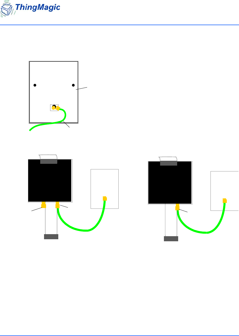
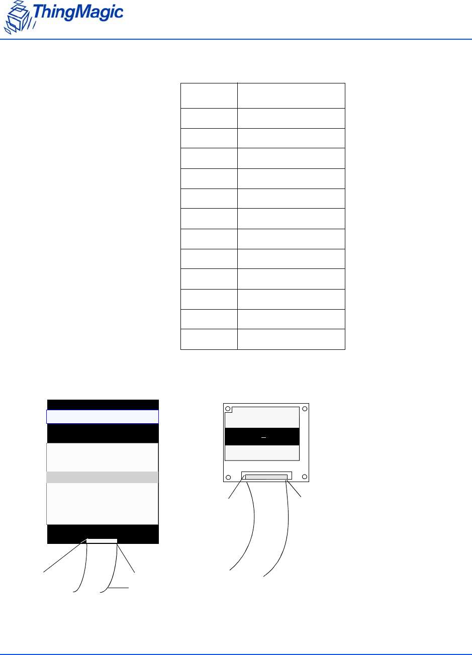
Attaching the Antenna
The antenna cable is attached to the Mercury5e or M5e-Compact reader at J2. The other end
of the cable is attached to the antenna.
Use the following procedure to connect a monostatic antenna to the reader.
Attaching the Antenna
Chapter 2: Setting Up the Reader 5
To attach a monostatic antenna:
1. Connect one end of the coax cable to the antenna.
2. Connect the other end of the cable to J 2.
Antenna
Coax cable
M5e
Term inat or
J2
M5e-C
J2
Powering Up the Reader
Chapter 2: Setting Up the Reader 6
3. Attach a terminator to the open antenna port.
When using a monostatic antenna, terminate the unused port (on the M5e) before the
reader is powered on. If no terminator is available, a 3 dB attenuator can be substituted.
Powering Up the Reader
After connecting the antenna and terminating the extra antenna, you can power up the reader.
To power up:
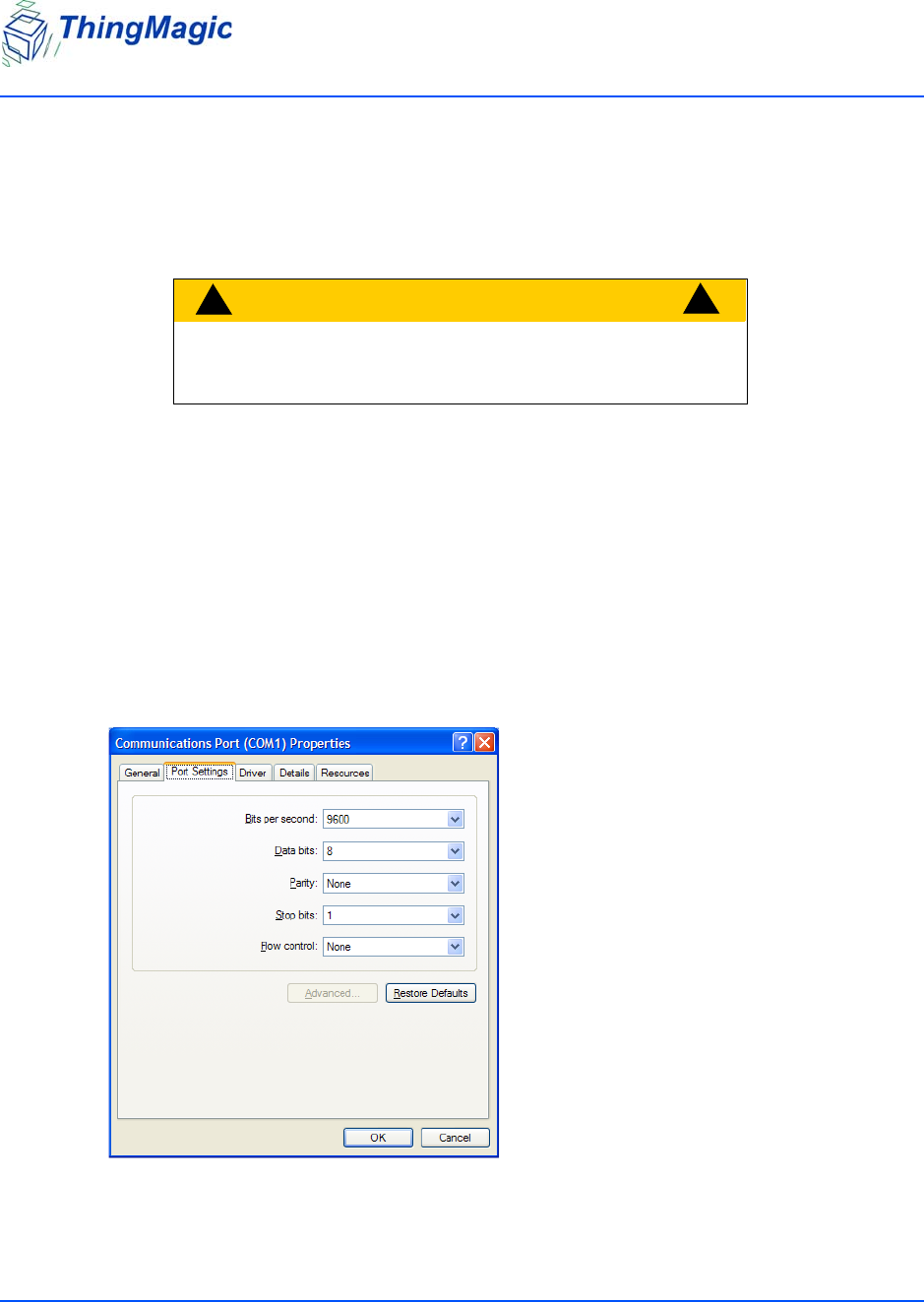
1. Connect a DB9 serial cable from a PC to the reader flex cable.
The async settings for the serial cable are:
CAUTION!
!!
An unterminated antenna port can be dam-
aged, if it is powered on.

Powering Up the Reader
Chapter 2: Setting Up the Reader 7
2. Attach a power supply into the reader’s electrical connection.
3. Connect the power supply to a 100–240 VAC power outlet.
The reader begins to power up.
Continue with the next chapter to start reading tags.

Chapter 3: Using the Reader Assistant 8
Chapter 3: Using the Reader Assistant
The Reader Assistant is a graphical user interface developed to allow you to communicate with
the DevKits and Mercury embedded modules.
From the Reader Assistant, you can perform the following tasks:
Read tags
Write to tags
Configure the reader
Update applications in flash memory
Load new firmware
If you select Options > Show Advanced Features or press Ctrl+A, the Tag Operations
Debugand tabs appear. From these tabs, you can perform the following tasks:
Write tag ids
Read and Write tag data
Kill and Lock tags
Debug using scripts

Starting the Reader Assistant
Chapter 3: Using the Reader Assistant 9
Starting the Reader Assistant
The following procedure explains how to install and activate the Reader Assistant on your
computer system.
To start the Reader Assistant and set up the serial port:
1. Copy the ReaderAssistant folder from the CD to a computer that is used to connect to the
embedded module or run the executable file from the CD.
2. Set up the computer to the embedded module as described in the Mercury Embedded
Modules DevKit Set Up Sheet.
3. Double-click the executable file ReaderAssistant.exe.
The Reader Assistant Splash screen appears and then the Reader Assistant opens.
Communication Settings
Chapter 3: Using the Reader Assistant 10
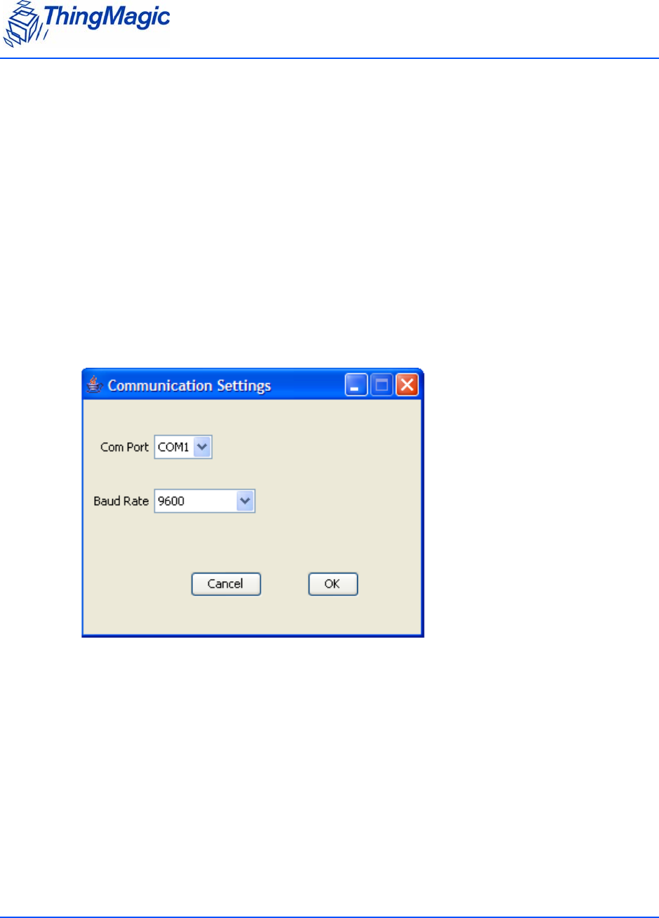
Communication Settings
You use the Communication Settings screen to set the Com Port and the baud rate. It can also
configure the baud rate used by the reader.
The Communication Settings screen displays automatically the first time the Reader Assistant is
launched. The Communication Settings screen also displays when the application settings file
application_settings.dat is deleted.
Otherwise, you can access the screen using the following procedure.
To access the Communication Settings screen:
1. Select Options > Communication Settings and the following dialog opens.
The Reader detects the COM Port that is on the computer system.
Note: If the Reader is attached to a different COM port, you have to choose the port from
the list.
2. From the Baud Rate menu, choose a communication rate. The default is 9600.
3. Click OK to close the Communications Settings screen.
Communication Settings
Chapter 3: Using the Reader Assistant 11
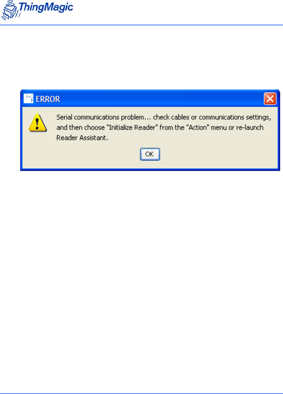
Serial Communications Problem
If the host computer and the reader lose communications, an alert screen displays that warns
you of the problem. The alert displays if the response message fails to arrive after a timeout
period or if the response message contains an invalid CRC.
.

Menu Commands
Chapter 3: Using the Reader Assistant 12
Menu Commands
The menu commands, File, Options, and Action provide additional actions that you can take in
the Reader Assistant.
File menu
The File menu has the following commands:
Save Application Settings – Ctrl+S
Quit – Ctrl+Q
Save Serial Log - Saves the current serial log to a file. Please note the default name for
the save file is always offered and no checks are made for overwriting an existing file.
Options menu
The Options menu has the commands:
Communication Settings
Show Serial Log – Ctrl+L
Show Advanced Features – Ctrl+A
Action menu
The Action menu has the following commands:
Re-Synch Application and Reader – Ctrl+R
Selecting this action attempts to update the Reader Assistant with the current settings
of the module. This should not be used if the devkit/module has been disconnected or
swapped with another devkit/module. In that case the Reader Assistant should be
restarted.
Reset Reader
Selecting this action resets all module settings to their default values.

Configuring the Reader
Chapter 3: Using the Reader Assistant 13
Configuring the Reader
The Config tab allows you to configure the reader settings. All the settings are displayed in the
Serial Log. For information about each setting, see the Config Tab Settings.
Note
Be sure to set the antenna port before attempting to read tags. Otherwise, the
reader cannot read tags.
The following table explains the reader Config tab settings:
Config Tab Settings
Name Description
Antenna Port Select one of the following:
Monostatic
Bistatic
Read Power (dBm) Move the slider or click the up or down arrow to
change the read power. The default is 100% or
30dBm on the Mercury5e and 23dBm on the M5e-
Compact.
Write Power (dBm) Move the slider or click the up or down arrow to
change the write power. The default is 100% or
30dBm on the Mercury5e and 23dBm on the M5e-
Compact.
Protocol Select a protocol to use.
M4e: EPC0/EPC0+Matrics, EPC1, ISO18k-6B,
EPC0+Impinj, GEN2, UCODE
M5e: GEN2.
User Mode (M5e/M5e-Compact
only)
Select one of the following modes:
0x00. Default
0x01. Printer
0x03. Portal

Configuring the Reader
Chapter 3: Using the Reader Assistant 14
To change Config settings:
1. Select the antenna port you are using from the Antenna Port menu.
2. Set read and write power by doing one of the following tasks:
Moving the Read Power slider or Write Power slider
Changing the power percentage by clicking the up or down arrows.
3. Select a protocol from the Protocol menu.
For M5e/M5e-Compact, GEN2 is the only protocol supported.
Advanced Settings
Power Save Mode (M5e/M5e-Com-
pact only)
Allows you to set power saving modes:
0x00. Full Power Mode – Operates at full
power
0x01. Minimal Savings Mode – Saves power
without degrading system performance, 10 ms
delay.
0x02. Medium Savings Mode – Shuts down
analog section between serial commands and
restarts when a command is issued, 50 ms delay.
0x03. Maximum Savings Mode/Deep
Sleep– Shuts down board, only powers the proces-
sor, restarts when a command is issued, up to 200
ms delay.
GPIO Input #1
GPIO Input #2
Gets the GPIO setting.
Click the Get GPIO Inputs button.
GPIO Output #1
GPIO Output # 2
Sets the GPIO setting:
Low | High
Gen2 Session Sets the Gen2 Session to use for tag operations.
Max. EPC Length Sets the maximum size EPC that can be read. When
set to 496, shorter EPCs will still be read.
Antenna Port Termination Checks for antennas or terminators on the antenna
ports and displays the status.
Temperature Gets the current temperature of board components.
Transmit Modes Sets the transmit mode to use (if applicable):
0x00 High Performance Mode
0x01 Low Powr Mode.
Name Description

Configuring the Reader
Chapter 3: Using the Reader Assistant 15
4. For M5e/M5e-Compact only, select a User Mode and a Power Mode.
Note
Select User Mode 01 (Printer) or Gen2 Session=0 for maximum read rate on individual
tags. Selecting User Modes where the Gen2 Session=1 (User Modes 00 or 03) may
result in a slow single tag read rate.
Reading and Writing to Tags
Chapter 3: Using the Reader Assistant 16
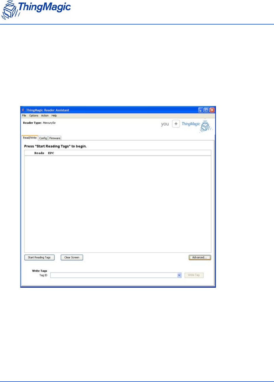
Reading and Writing to Tags
The Read/Write tab can be used to quickly read tags to verify that the reader is working
correctly. Set up the reader and provide tags to read. See the Mercury Embedded Modules
DevKit Set Up Sheet provided with the DevKit.
When you are connected, the reader type shows in the top field.
Reading and Writing to Tags
Chapter 3: Using the Reader Assistant 17
To read tags from the Read/Write tab:
1. Click Start Reading Tags.
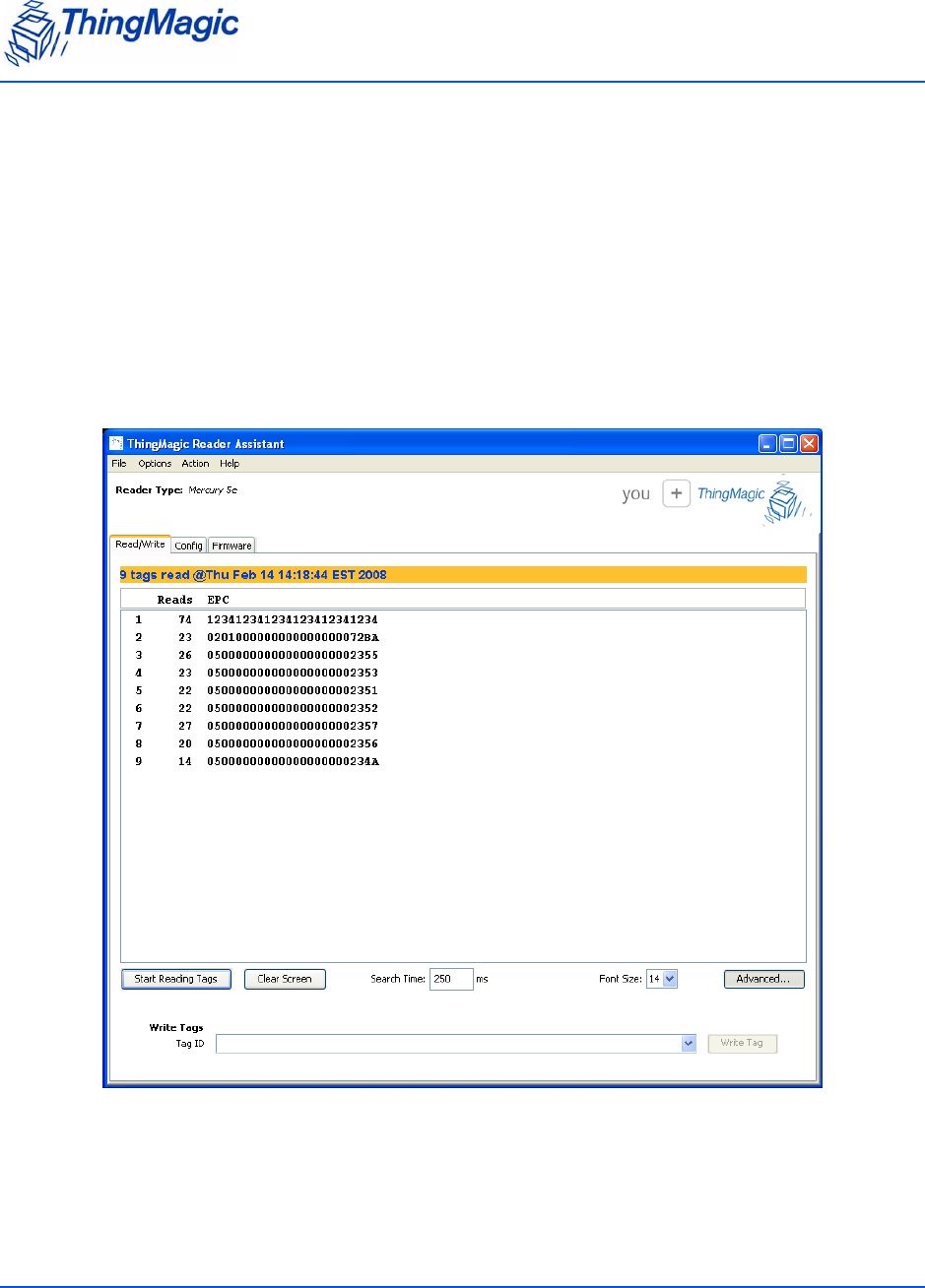
The reader reads the tags and starts to display the EPCs and the running total number of
times each EPC has been read (Reads) in the Read/Write screen.
A yellow background is displayed with the date and timestamp as each tag is read. The
most recently read tags display white backgrounds. The background gets darker as the
time from when the tags were last read gets longer. See tag 6.
2. To stop reading tags, click Stop Reading Tags.
3. When the demo is complete, click Clear Screen to remove the information displayed on
the screen.
Reading and Writing to Tags
Chapter 3: Using the Reader Assistant 18
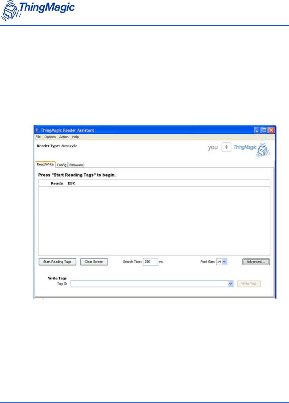
Advanced Settings
You can access additional functionality by clicking Advanced. The functions include setting
the search time, changing the font size, and writing to tags.
To use advanced features:
1. Click Advanced.
The following additional functions appear on the Read/Write screen.
2. Type a new value in the Search Time field to change the time in milliseconds.
3. Click the Font Size drop-down menu to change the size of the font in the screen.
4. To write to a tag, follow these steps:
a. Type a valid tag id in the Tag ID field.
The Write Tag button activates when you enter the tag id.
Note: A valid tag ID is represented in hexadecimal format (multiples of four digits).

Reading and Writing to Tags
Chapter 3: Using the Reader Assistant 19
b. Click Write Tag.
A dialog opens to verify the tag id you want written.
c. Click OK.
Serial Log
Chapter 3: Using the Reader Assistant 20
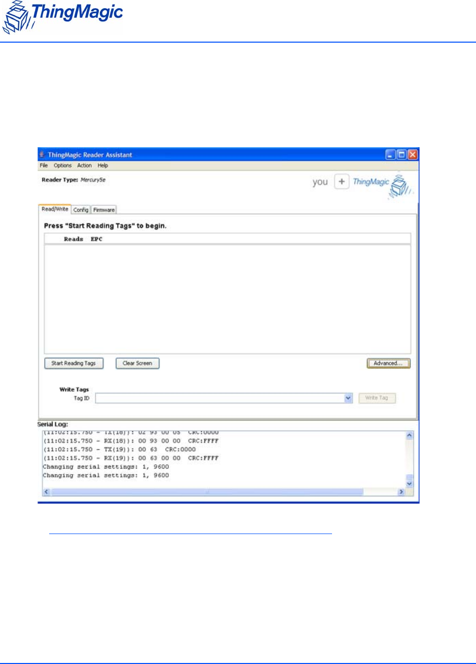
Serial Log
You can open a panel in any screen to display the Serial Log. To access the Serial Log, select
Options > Show Serial Log.
Note
To save the current Serial Log to a file selct File > Save Serial Log.
Loading FW and Using the Flash Area
Chapter 3: Using the Reader Assistant 21
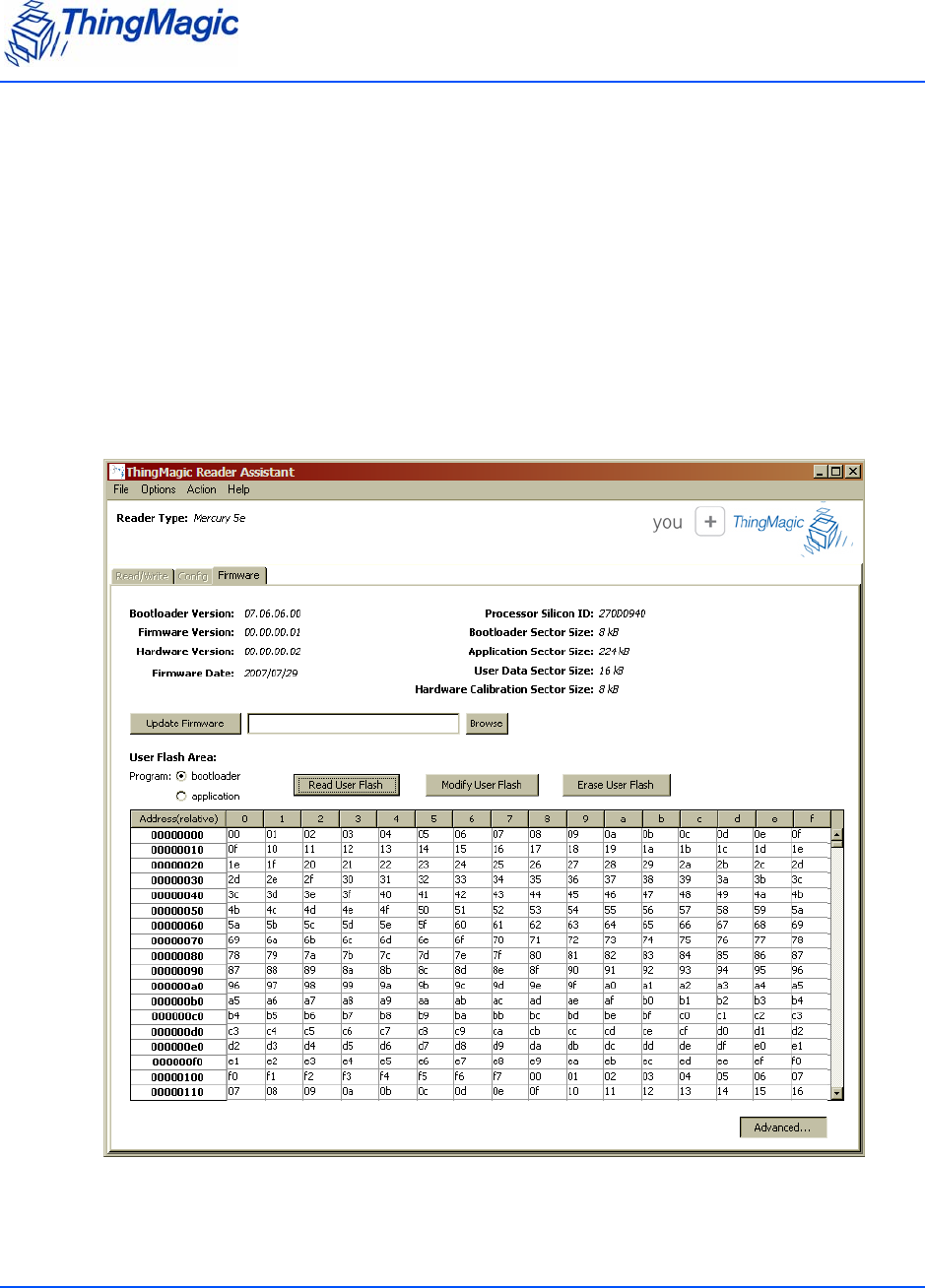
Loading FW and Using the Flash Area
The Firmware tab restarts the reader when it is selected. You can load the latest firmware
from this screen. With the Advanced settings, you can read and write to the user flash area.
There are three main functional sections within this tab.
System Configuration section – displays version information from the reader.
Application Image section – loads the FW image in one step.
User Flash Area – allows the user to examine and change the user flash area of the
reader. To access, press Advanced.
.

Loading FW and Using the Flash Area
Chapter 3: Using the Reader Assistant 22
Note
If you have selected the Bootloader radio button under User Flash Area, all other
Reader Assistant tabs will be disabled. You must select the Application radio
button to re-enabled the other tabs.

Loading FW and Using the Flash Area
Chapter 3: Using the Reader Assistant 23
The following table explains the Firmware tab settings:
Firmware Tab Settings
Name Description
Bootloader Version The latest Bootloader installed. Gets the version number
from the reader.
Firmware Version The most recent installed firmware. Gets the version num-
ber from the reader
Hardware Version The version of the hardware when it was built. Gets the
version number from the reader.
Firmware Date Date that the latest firmware was installed. Gets the date
from the reader
Processor Silicon ID Gets the identification from the reader
Bootloader Sector Size Gets the sector size from the reader
Application Sector Size Gets the sector size from the reader
User Data Sector Size Gets the sector size from the reader
Hardware Calibration Sector Size Gets the sector size from the reader
Firmware file field Do one of the following to load the file:
• Type a file name in the field.
• Click Browse to find the file on the system.
Update Firmware button Click to update the firmware shown in the Firmware file
field.
Advanced Settings
User Flash Area: Bootloader radio button: Click to access the bootloader
program.
Application radio button: Click to return to the applica-
tion.
Read User Flash button Click to display the user flash memory in the screen.
Modify User Flash button Click a section of memory to select it, enter new byte val-
ues, and then click the button to change the user flash
memory in the location selected.
Erase User Flash button Click a section of memory to select it and then click the
button to erase the user flash memory in the location
selected.

Working with Tags
Chapter 3: Using the Reader Assistant 24
To modify the user flash area:
1. Click the Bootloader radio button to access the bootloader program.
The user flash area is only accessible from the bootloader.
2. Click Read User Flash to populate the table with the contents of the flash.
3. To modify the flash contents, follow these steps:
a. Enter different byte values in the cells of the table.
b. Click Modify User Flash to commit the modifications to the user flash area on the
reader.
4. To erase the flash contents, follow these steps:
a. Click in the table to select a section.
b. Click Erase User Flash to delete the values in that section.
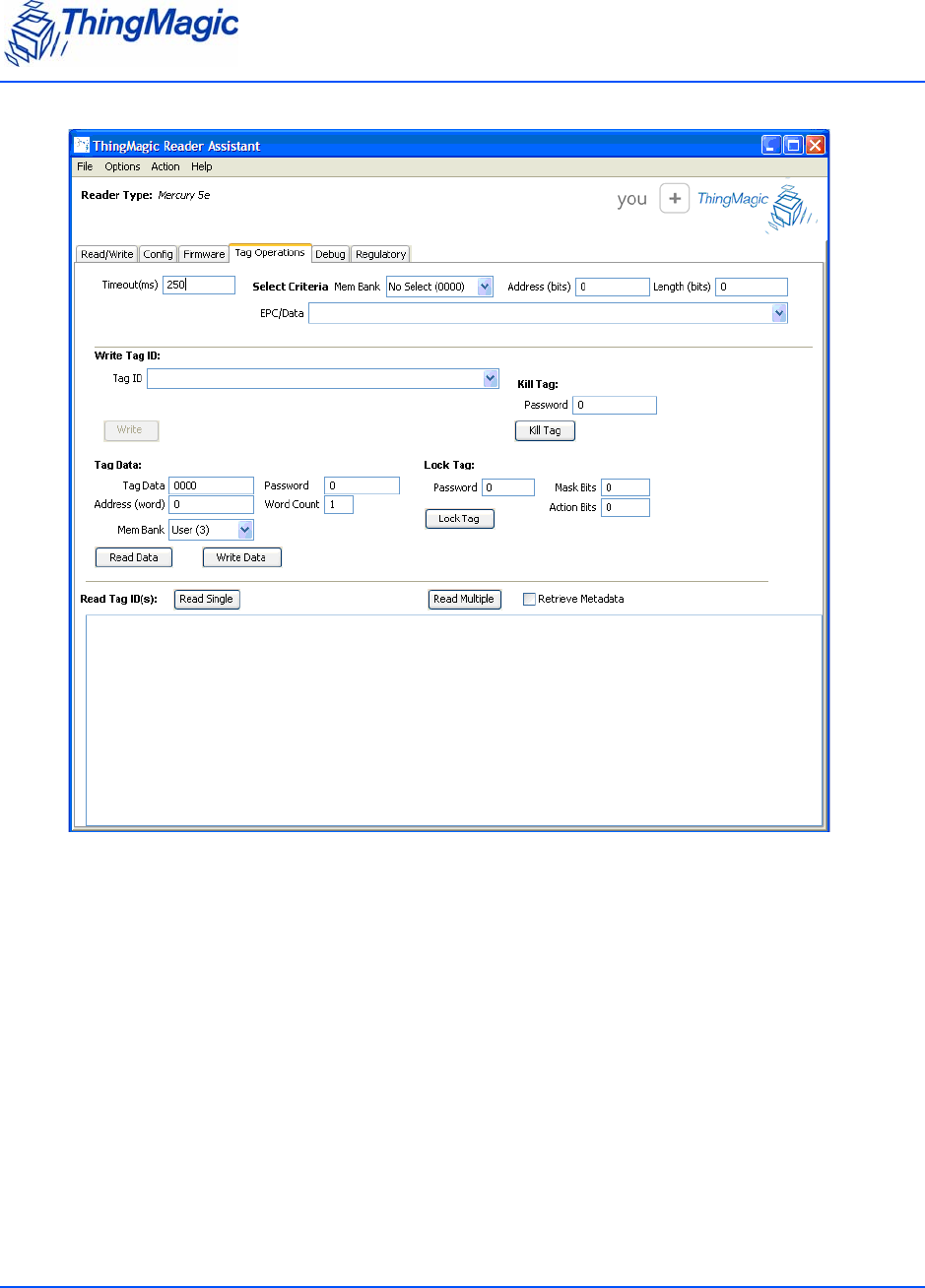
Working with Tags
The Tag Operations tab lets you perform various tag operations without having to write a
program. You use this screen when you want to read or write tag data, lock or kill tags.
Tag Operations Tab
To access this tab, select Options > Show Advanced Features or press Ctrl+A and
additional tabs become available.
Working with Tags
Chapter 3: Using the Reader Assistant 25

Working with Tags
Chapter 3: Using the Reader Assistant 26
The following table explains the Tag Operations tab settings:
Tag Operations Tab Settings
Grouping
Name Description
Universal
Time out (msec) Timeout for all commands that require it.
Select Criteria
Mem Bank Drop-down selection that controls both the Select operation
mode and the memory area that is the target of the Select cri-
teria:
• No Select (00): First tag to respond is acted on (Select
is not enabled)
• EPC (01): Select tag based on full or partial left-justified
EPC value, specified by Length and EPC/Data field
values.
• TID (02): Select tag based on any value within User
memory field, specified by Address, Length, Select and
ECP/Data field values
• User (03): Select tag based on any value within User
memory field, specified by Address, Length, Select and
ECP/Data field values
• EPC Mem (04): Select tag based on any value within
EPC memory field, specified by Address, Length and
EPC/Data field values.
Address Start address of Select criteria, in hex (maximum of 4 bytes).
Used for TID, User and EPC Mem Select modes. Leave at ‘0’
for No Select and EPC Select modes.
Length Length of the Select criteria, in bits (integer). Used for EPC,
TID, User and EPC Mem Select modes. Leave at ‘0’ for No
Select mode. Can be shorter but cannot be longer than the
value in EPC/Data field.
EPC/Data Value, in hex, of data to be compared with the value within tag
memory. Must be an even number of words (4 hex digits per
word) for EPC and EPC Mem Select modes. Leave blank for
No Select mode.
Write Tag ID
Tag ID EPC to write to a tag (hex). Must be in word (4 hex digits per
word) multiples.
Write button Executes the EPC (Tag ID) Write to the first tag to respond.

Working with Tags
Chapter 3: Using the Reader Assistant 27
Tag Data
Tag Data Data bytes, in hex, to be written to a tag when “Write Data”
button is pressed.
Address Start location within memory bank for “Read Data” or “Write
Data” functions, in words. Maximum of 4 bytes (8 hex digits).
Mem Bank Drop-down select of memory bank to be written to or read.
Password 4 byte password, in hex, to be entered if needed for “Read
Data” or “Write Data” operations. If not needed (tag is not
locked), leave as “0”.
Word Count Number of words as an integer value to be read for “Read
Data”. Not used for “Write Data”
Read Data button Press to read data from memory as specified by Mem Bank,
Address and Word Count settings. Enabled by Password
entry, if needed.
Write Data button Press to write data to memory as determined by Mem Bank,
Tag Data, and Address settings (enabled by Password entry, if
needed). Word Count value is ignored. If Select Criteria Mem
Bank value is any value but No Select then the first tag which
meets the Select Criteria is written to.
Kill Tag
Password The tags 4 byte, in hex, kill password of the tag. Require to be
non-Zero to kill a tag.
Kill Tag button Press to kill the tag.
Lock Tag
Password The tags 4 byte, in hex, access password if the lock tag pass-
word is set.
Mask Bits Bit-wise mask, in hex, specifying which action bits to
pass
1. Causes the corresponding bit in the Action field to be
applied.
0. Ignores the corresponding bit in the Action field.
Action Bits Bit-wise value, in hex, specifying what locking action to
apply to memory banks.
1. Asserts lock (read, read/write, or permanent) memory loca-
tion based on bit location.
0. De-asserts lock.
Lock Tag button Press to lock the tag.
Grouping
Name Description

Working with Tags
Chapter 3: Using the Reader Assistant 28
Note
Depending on the module you are using and the protocol setting in the Config
tab, you may see different fields in the Tag Operations tab.
Write Tag ID
The Tag Operations tab provides settings to write an EPC to a tag. The following procedure
explains how to write to a tag using the fields under Write Tag ID.
To write a tag EPC:
1. Type the EPC into the Tag ID field or select an EPC used previously.
2. Type a time in milliseconds in the Timeout(ms) field.
3. Click Write.
The tag EPC information is displayed in the Serial Log field.
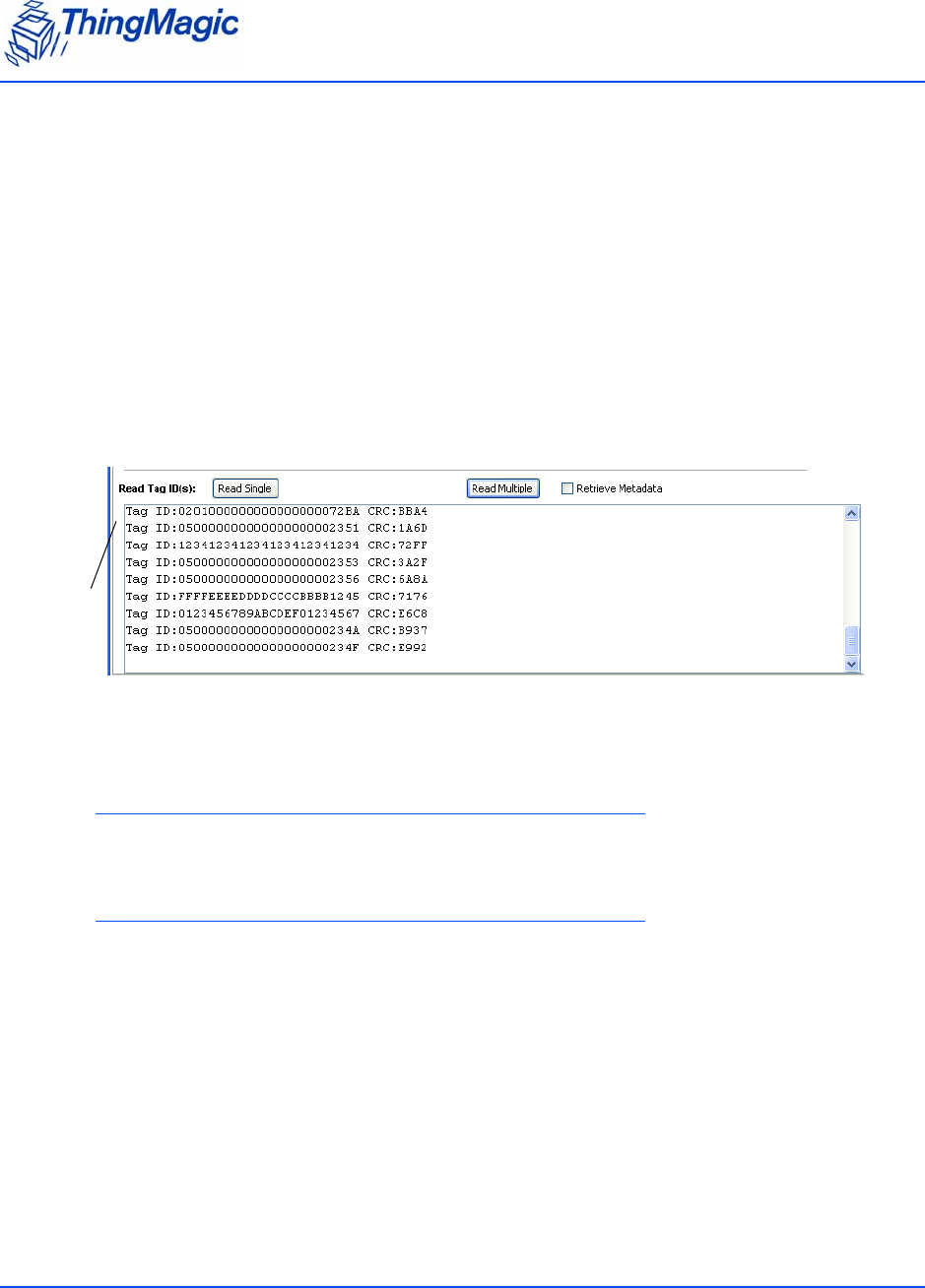
Read Tag IDs
Read Single button Press to display the EPC of the first tag that responds. If
the maximum EPC size is 496 bits and the tag has an
EPC longer than 96 bits the tag will be read, but only the
first 96 bits are displayed in the results field.
Read Multiple button When pressed, information from all tags that respond
will be collected and displayed until the Timeout expires.
Metadata is also displayed if the ‘Retrieve Metadata’
checkbox is selected.
Retrieve Metadata checkbox If select tag metadata is displayed in the results field. Does
not apply to Read Single. Metadata fields are:
• Count: number of time tag was read during Read
Multiple operation.
• RSSI: indication of relative receive signal strength from
tag
• TX: antenna port from which signal was transmitted
when tag was read
• RX: antenna port from which signal was received when
tag was read.
• Freq: Channel frequency when tag was read.
• Time: time at which tag was read
Grouping
Name Description

Working with Tags
Chapter 3: Using the Reader Assistant 29
Reading Tag Data
The following procedure explains how to read tag data.
To read tag data:
1. Type an address location in the Address field.
2. Choose a selection from the Mem Bank menu.
3. Click Read Data and the information is shown in the Read Tag IDs field.
Writing Tag Data
First determine whether the first tag to respond will be written to or whether the first tag
matching the Select criteria is to be written to, based on the Select Criteria Mem Bank
selection. Note that if the Write changes the data in the fields used for Select Criteria, the
subsequent Verify will fail, even though the tag will have been successfully written.
No Select(00): Used when the “Write Data” action is to be applied to the first tag to
respond.
EPC(01): Used to write to a tag selectively based on the full or partial (starting at lowest
memory location) EPC of the tag. EPC to be compared must be entered as a multiple of
words (4 hex digits). This Select operation mode provides a subset of the functionality
provided by mode “EPC Mem”, but is easier to use.
1. Enter the EPC or partial EPC (multiples of 4 hex digits, each representing a word)
2. Enter the length, in bits, of the portion of the EPC to be compared, as an integer. Only
the portion of the EPC specified by the length will be compared. (“0” will always
match). The length cannot exceed the entered EPC length.
TID (02): Used to write to a tag selectively based on the any portion of the TID memory
contents of the tag.
1. Enter the data to be compared in bytes
2. Enter the starting address bit offset from the start of memory in hex (4 bytes
maximum)
3. Enter the length, in bits, of the portion of the data to be compared, as an integer. Only
the portion of the data specified by the length will be compared. (“0” will always
match). The length cannot exceed the entered data length.
User (03): Used to write to a tag selectively based on the any portion of the User
memory contents of the tag.

Working with Tags
Chapter 3: Using the Reader Assistant 30
1. Enter the data to be compared in bytes
2. Enter the starting address bit offset from the start of memory in hex (4 bytes
maximum)
3. Enter the length, in bits, of the portion of the data to be compared, as an integer. Only
the portion of the data specified by the length will be compared. (“0” will always
match). The length cannot exceed the entered data length.
EPC Mem (04): Used to write to a tag selectively based on the any portion of the EPC
memory contents of the tag. Used in place of the “EPC” operation mode when the PC bits
are the target of the comparison or the portion of the EPC to be compared does not start
at the lowest memory location. Note that the EPC itself starts16 bits into memory.
1. Enter the data to be compared in bytes
2. Enter the starting address bit offset from the start of memory in hex (4 bytes
maximum). Note that the PC bits start at hex “10” and the EPC starts at hex “20”
3. Enter the length, in bits, of the portion of the data to be compared, as an integer. Only
the portion of the data specified by the length will be compared. (“0” will always
match). The length cannot exceed the entered data length.
Once the tag singulation method is set, to perform the write, follow these steps.
To write tag data:
1. Type a hex code in the Tag ID field.
2. Choose a selection from the Mem Bank menu.
3. Type an address location in the Address field.
4. Click Write Data.
Killing Tags
The Tag Operations tab provides settings to kill tags. Once you kill a tag, it cannot be used
again.
To kill a tag:
1. Type the password that allows you to kill the tag.
2. Click Kill Tag to delete the tag.

Working with Tags
Chapter 3: Using the Reader Assistant 31
Locking Tags
The Lock tag area of the Tag Operations tab locks a specific address in the tag data section.
To lock a tag:
1. Type the 32-bit password that allows you to lock the tag.
If a password is not set in the tag, type 0.
2. Set the Mask Bit field as described in the Mercury Embedded Developer’s Guide: Lock
Tag (25h).
3. Set the Action Bit field.
4. Click Lock Tag to lock the data in the tag.
Working with Tags
Chapter 3: Using the Reader Assistant 32
Reading Tags
The M5e reader can use the settings in the Tag Operations tab to read the tag EPCs and
retrieve the tag read metadata. You can read a single tag or multiple tags.
To read tags:
1. Type in the amount of time in which you want the reader to read tags.
2. To read a single tag, click Read Single.
3. To read multiple tags, click Read Multiple.
The tag ids are displayed in the text field.
Note
Retrieve Metadata will only return tag read metadata when used with Read
Multiple.
Note
Tags are only read on the configured antenna. The Read Multiple button does not
support Multi-antenna Search.
TAG DATA
Debugging the Module
Chapter 3: Using the Reader Assistant 33
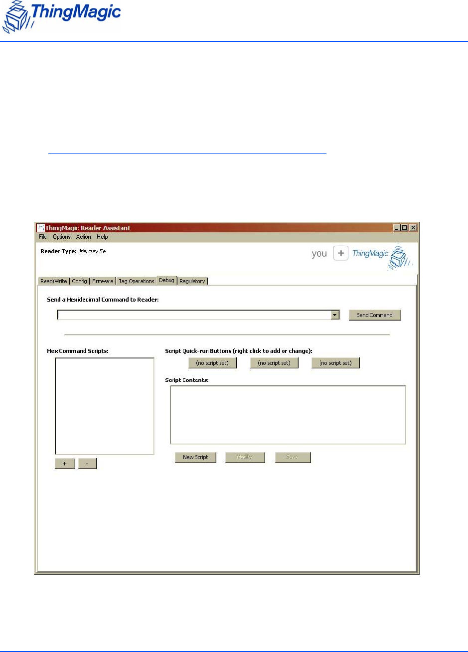
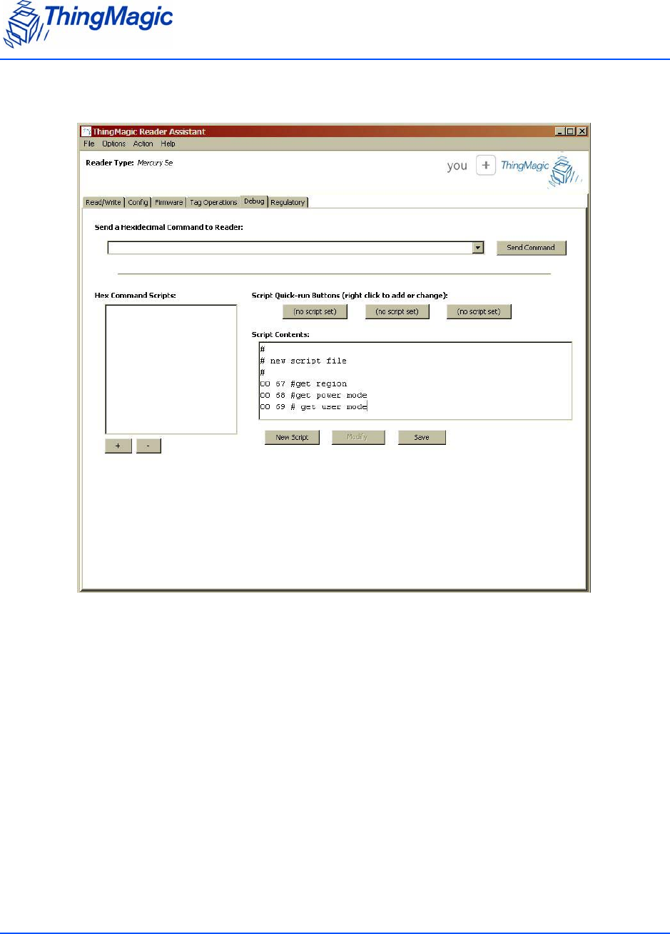
Debugging the Module
The Debug tab sends serial commands to the reader using hexadecimal format. You can also
add scripts containing sequences of commands to the Script Contents panel.
Note
Write the scripts in a text editor and then add them to the New Command Scripts
list.
If you do not see the Debug tab, press Ctrl+A.

Debugging the Module
Chapter 3: Using the Reader Assistant 34
Debug Tab Settings
To create a script:
1. Click New Script and the following is displayed in the Scripts Contents panel.
Name Description
Send a Hexadecimal Command
to Reader field
Enter the command you want to send in hex for-
mat.
Send Command button Click to send the command.
Hex Command Scripts Lists the scripts that you added to the screen.
Script Quick-run buttons Select a script and right-click a button to add
the script to that button.
Note: If you are running two scripts frequently,
this is a quick way of selecting the two
scripts to run.
Script Contents This panel has the following functions:
• Script editor for creating scripts.
• Displays a selected script.
New Script button Click to create a script in the Script Contents
panel.
Modify button Click to change a stored script.
Save button Click to save a script.
+ button Opens a dialog box to select the saved scripts
you created to add to the list.
– button Removes a script from the list.
Debugging the Module
Chapter 3: Using the Reader Assistant 35
2. Type the script within the panel and click Save.
A Save as dialog opens and you can save your script.
3. To change the script, click Modify.
4. To run the script, right click a Script Quick-run button to attach the script to the button.
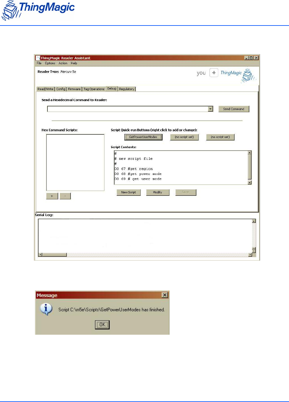
Debugging the Module
Chapter 3: Using the Reader Assistant 36
5. Click the Script Quick-run button to run the script.
After the script is finished running, the following dialog appears.
6. Click OK and the results appear in the Serial Log panel.
7. To see the results from the Send a Hexadecimal Command to Reader field or to
execute the Hex Command Script, select Action > Re-Synch Application and
Reader.

Chapter 3: Using the Reader Assistant 37

38

A-39
Appendix A: Hardware Details
This Appendix details the mechanicals for the embedded modules and also provides pin 1
locations for the M5e and M5e-Compact serial connectors.
Mechanicals
The following figures detail the hardware layouts that comprise the Mercury Embedded
Modules.

Mechanicals
A-40
M5e Mechanicals

Mechanicals
A-41
M5e-Compact Mechanical
Antenna Connector
The M5e has two MMCX connectors and the M5e-Compact has one MMCX connector for
interfacing to the antennas.
Communications Connector
The communications interface on the modules provides power, serial communications signals,
and access to the GPIO inputs and outputs.
The M5e and M5e-Compact have a 12-pin connector with the following pin-out:
Mechanicals
A-42
Pin-out of the 12-pin digital connector
The following figure shows the diagrams of the M5e, and M5e-Compact communications
interface as you face the boards..
Pin # Signal
1+5V
2+5V
3 GND
4 GND
5 Digital Output 1
6 Digital Output 2
7 Digital Input 1
8 Digital Input 2
9 RS-232 RX from host
10 RS-232 TX to host
11 Mfg test purposes
12 Mfg test purposes
Pin 1 Pin 12
Ribbon cable
Pin 12Pin 1
M5e-C
M5e M5e Compact

Mechanicals
A-43
Note
The flat ribbon cable that connects with the communications interface on the
M5e and M5e-Compact embedded modules is available from Parlex,
Part Number: 100R12-152B; and can be purchased from standard electronic
component suppliers.

Mechanicals
A-44

45
Appendix B: Error Messages
The following error codes were incorporated into the reader for help in locating errors.
Common Error Messages
The following table lists the common faults discussed in this section.
FAULT_MSG_WRONG_NUMBER_OF_DATA – (100h)
Cause
If the data length in any of the Host-to-M5e/M5e-Compact messages is less than or more than
the number of arguments in the message, the reader returns this message.
Solution
Make sure the number of arguments matches the data length.
Fault Message Code
FAULT_MSG_WRONG_NUMBER_OF_DATA – (100h) 100h
FAULT_INVALID_OPCODE – (101h) 101h
FAULT_UNIMPLEMENTED_OPCODE – 102h 102h
FAULT_MSG_POWER_TOO_HIGH – 103h 103h
FAULT_MSG_INVALID_FREQ_RECEIVED (104h) 104h
FAULT_MSG_INVALID_PARAMETER_VALUE - (105h) 105h
FAULT_MSG_POWER_TOO_LOW - (106h) 106h
FAULT_UNIMPLEMENTED_FEATURE - (109h) 109h
FAULT_INVALID_BAUD_RATE - (10Ah) 10Ah

Common Error Messages
46
FAULT_INVALID_OPCODE – (101h)
Cause
The opCode received is invalid or not supported with the current version of code.
Solution
Check the documentation for the opCode the host sent and make sure it is supported.
FAULT_UNIMPLEMENTED_OPCODE – 102h
Cause
Some of the reserved commands might return this error code.
This does not mean that they always will do this since ThingMagic reserves the right to modify
those commands at anytime.
Solution
Check the documentation for the opCode the host sent to the reader and make sure it is
supported.
FAULT_MSG_POWER_TOO_HIGH – 103h
Cause
A message was sent to set the read or write power to a level that is higher than the current HW
supports.
Solution
Check the HW specifications for the supported powers and insure that the level is not
exceeded.
The M5e 1 Watt units support power from 5 dBm to 30 dBm.
The M5e-Compact units support power from 10 dBm to 23 dBm.

Common Error Messages
47
FAULT_MSG_INVALID_FREQ_RECEIVED (104h)
Cause
A message was received by the reader to set the frequency outside the supported range
Solution
Make sure the host does not set the frequency outside this range or any other locally supported
ranges.
FAULT_MSG_INVALID_PARAMETER_VALUE - (105h)
Cause
The reader received a valid command with an unsupported or invalid value within this command.
For example, currently the module supports two antennas, 1 and 2. If the module receives a
message with an antenna value other than 1 or 2, it returns this error.
Solution
Make sure the host sets all the values in a command according to the values published in this
document.
FAULT_MSG_POWER_TOO_LOW - (106h)
Cause
A message was received to set the read or write power to a level that is lower than the current
HW supports.
Solution
Check the HW specifications for the supported powers and insure that that level is not
exceeded. The M5e supports powers between 5 and 30 dBm. The M5e-Compact units support
power from 10 dBm to 23 dBm.

Common Error Messages
48
FAULT_UNIMPLEMENTED_FEATURE - (109h)
Cause
Attempting to invoke a command not supported on this firmware or hardware.
Solution
Check the command being invoked against the documentation.
FAULT_INVALID_BAUD_RATE - (10Ah)
Cause
When a Set Baud Rate (0x06h) command is issued for a rate that is not specified in the Baud
Rate table, this error message is returned.
Solution
Check the table of specific baud rates and select a baud rate. Send the baud rate in the hex
format.

Bootloader Faults
49
Bootloader Faults
The following table lists the common faults discussed in this section.
FAULT_BL_INVALID_IMAGE_CRC – 200h
Cause
When a Verify Image CRC (0x08), or Boot Firmware (0x02) command is issued, the reader
checks the image stored in flash and returns this error if the calculated CRC is different than
the one stored in flash.
Solution
The exact reason for the corruption could be that the image loaded in flash was corrupted
during the transfer or corrupted for some other reason.
To fix this problem, reload the application code in flash.
FAULT_BL_INVALID_APP_END_ADDR – 201h
Cause
When a Verify Image CRC (0x08), or Boot Firmware (0x02) command is issued, the reader
checks the image stored in flash and returns this error if the last word stored in flash does not
have the correct address value.
Solution
The exact reason for the corruption could be that the image loaded in flash got corrupted
during the transfer or, corrupted for some other reason.
To fix this problem, reload the application code in flash.
Fault Message Code
FAULT_BL_INVALID_IMAGE_CRC 200h
FAULT_BL_INVALID_APP_END_ADDR 201h

Flash Faults
50
Flash Faults
The following table lists the common faults discussed in this section.
FAULT_FLASH_BAD_ERASE_PASSWORD – 300h
Cause
A command was received to erase some part of the flash but the password supplied with the
command was incorrect.
Solution
Make sure that you have the correct password for the flash sector.
FAULT_FLASH_BAD_WRITE_PASSWORD – 301h
Cause
A command was received to write some part of the flash but the password supplied with the
command was not correct.
Solution
Make sure that you have the correct password for the flash sector.
Fault Message Code
FAULT_FLASH_BAD_ERASE_PASSWORD – 300h 300h
FAULT_FLASH_BAD_WRITE_PASSWORD – 301h 301h
FAULT_FLASH_UNDEFINED_ERROR – 302h 302h
FAULT_FLASH_ILLEGAL_SECTOR – 303h 303h
FAULT_FLASH_WRITE_TO_NON_ERASED_AREA – 304h 304h
FAULT_FLASH_WRITE_TO_ILLEGAL_SECTOR – 305h 305h
FAULT_FLASH_VERIFY_FAILED – 306h 306h

Flash Faults
51
FAULT_FLASH_UNDEFINED_ERROR – 302h
Cause
This is an internal error and it is caused by a software problem in module.
Solution
Contact support at support@thingmagic.com.
FAULT_FLASH_ILLEGAL_SECTOR – 303h
Cause
An erase or write flash command was received with the sector value and password not
matching.
Solution
Make sure that you have the correct password for the flash sector.
FAULT_FLASH_WRITE_TO_NON_ERASED_AREA – 304h
Cause
The module received a write flash command to an area of flash that was not previously erased.
Solution
Erase that sector of flash and then, try and rewrite to it.
FAULT_FLASH_WRITE_TO_ILLEGAL_SECTOR – 305h
Cause
The module received a write flash command to write across a sector boundary that is
prohibited.

Flash Faults
52
Solution
If the data spans two sectors, separate the data into two messages.
FAULT_FLASH_VERIFY_FAILED – 306h
Cause
The module received a write flash command that was unsuccessful because data being written
to flash contained an uneven number of bytes.
Solution
Verify that the data being sent is an even number of bytes.

Protocol Faults
53
Protocol Faults
The following table lists the common faults discussed in this section.
FAULT_NO_TAGS_FOUND – (400h)
Cause
A command was received (such as like read, write, or lock) but the operation failed. There are
many reasons that can cause this error to occur.
Fault Message Code
FAULT_NO_TAGS_FOUND – (400h) 400h
FAULT_NO_PROTOCOL_DEFINED – 401h 401h
FAULT_INVALID_PROTOCOL_SPECIFIED – 402h 402h
FAULT_WRITE_PASSED_LOCK_FAILED – 403h 403h
FAULT_PROTOCOL_NO_DATA_READ – 404h 404h
FAULT_AFE_NOT_ON – 405h 405h
FAULT_PROTOCOL_WRITE_FAILED – 406h 406h
FAULT_NOT_IMPLEMENTED_FOR_THIS_PROTOCOL – 407h 407h
FAULT_PROTOCOL_INVALID_WRITE_DATA – 408h 408h
FAULT_PROTOCOL_INVALID_ADDRESS – 409h 409h
FAULT_GENERAL_TAG_ERROR – 40Ah 40Ah
FAULT_DATA_TOO_LARGE – 40Bh 40Bh
FAULT_PROTOCOL_INVALID_KILL_PASSWORD – 40Ch 40Ch
FAULT_PROTOCOL_KILL_FAILED - 40Eh 40Eh
FAULT_GEN2 PROTOCOL_OTHER_ERROR - 420h 420h
FAULT_GEN2_PROTOCOL_MEMORY_OVERRUN_BAD_PC -
423h
423h
FAULT_GEN2 PROTOCOL_MEMORY_LOCKED - 424h 424h
FAULT_GEN2 PROTOCOL_INSUFFICIENT_POWER - 42Bh 42Bh
FAULT_GEN2 PROTOCOL_NON_SPECIFIC_ERROR - 42Fh 42Fh
FAULT_GEN2 PROTOCOL_UNKNOWN_ERROR - 430h 430h

Protocol Faults
54
Here is a list of possible reasons that could be causing this error:
No tag in the RF field
Read/write power too low
Antenna not connected
Tag is we a k or dead
Solution
Make sure there is a good tag in the field and all parameters are set up correctly. The best way
to check this is to try few tags of the same type to rule out a weak tag. If none passed, then it
could be SW configuration such as protocol value, antenna, and so forth, or a placement
configuration like a tag location.
FAULT_NO_PROTOCOL_DEFINED – 401h
Cause
A command was received to perform a protocol command but no protocol was initially set. The
reader powers up with no protocols set.
Solution
A Set Current Tag Protocol (63h) command must be sent followed by resending the desired
command.
FAULT_INVALID_PROTOCOL_SPECIFIED – 402h
Cause
A Set Current Tag Protocol (63h) command was received for a protocol value that is not
supported with the current version of SW.
Solution
This value is invalid or this version of SW does not support the protocol value. Check the
documentation for the correct values for the protocols in use.

Protocol Faults
55
FAULT_WRITE_PASSED_LOCK_FAILED – 403h
Cause
During a Write Tag Data for ISO18000-6B or UCODE, if the lock fails, this error is returned. The
write command passed but the lock did not. This could be a bad tag.
Solution
Try to write a few other tags and make sure that they are placed in the RF field.
FAULT_PROTOCOL_NO_DATA_READ – 404h
Cause
A Read Tag ID or Data command was sent but did not succeed.
Solution
The tag used has failed or does not have the correct CRC. Try to read a few others to check the
HW/SW configuration.
FAULT_AFE_NOT_ON – 405h
Cause
A command was received for an operation, like read or write, but the AFE was in the off state.
Solution
Start the AFE, then rerun the command.
FAULT_PROTOCOL_WRITE_FAILED – 406h
Cause
This fault can occur when an operation such as write, lock, kill, set password, or initialize, fails.
There are many reasons for failure.

Protocol Faults
56
Solution
Check that the tag is good and try another operation on a few more tags.
FAULT_NOT_IMPLEMENTED_FOR_THIS_PROTOCOL – 407h
Cause
A command was received which is not supported by a protocol.
Solution
Check the documentation for the supported commands and protocols.
FAULT_PROTOCOL_INVALID_WRITE_DATA – 408h
Cause
In EPC0+, the first two bits determine the tag ID length. If the first two bits are 0b00, then the
tag ID must be 96-bits. Otherwise the tag ID is 64 bits.
Solution
Make sure that the first two bit have the correct values depending in the Tag ID length.
FAULT_PROTOCOL_INVALID_ADDRESS – 409h
Cause
A command was received to write to an invalid address in the tag data address space.
Solution
Make sure that the address specified is within the scope of the tag data address space. The
protocol specifications contain information about the supported addresses.

Protocol Faults
57
FAULT_GENERAL_TAG_ERROR – 40Ah
Cause
This error is used by the M5e GEN2 module. This fault can occur if the read, write, lock, or kill
command fails. This error can be internal or functional.
Solution
Make a note of the operations you were performing and contact ThingMagic at http://
support.thingmagic.com
FAULT_DATA_TOO_LARGE – 40Bh
Cause
A command was received to Read Tag Data with a data value larger than expected or it is not
the correct size.
Solution
Check the size of the data value in the message sent to the reader.
FAULT_PROTOCOL_INVALID_KILL_PASSWORD – 40Ch
Cause
An incorrect kill password was received as part of the Kill Tag (26h) command.
Solution
Check the password.
FAULT_PROTOCOL_KILL_FAILED - 40Eh
Cause
Attempt to kill a tag failed for an unknown reason

Protocol Faults
58
Solution
Check tag is in RF field and the kill password.
FAULT_GEN2 PROTOCOL_OTHER_ERROR - 420h
FAULT_GEN2_PROTOCOL_MEMORY_OVERRUN_BAD_PC - 423h
FAULT_GEN2 PROTOCOL_MEMORY_LOCKED - 424h
FAULT_GEN2 PROTOCOL_INSUFFICIENT_POWER - 42Bh
FAULT_GEN2 PROTOCOL_NON_SPECIFIC_ERROR - 42Fh
FAULT_GEN2 PROTOCOL_UNKNOWN_ERROR - 430h

Analog Hardware Abstraction Layer Faults
59
Analog Hardware Abstraction Layer Faults
FAULT_AHAL_INVALID_FREQ – 500h
Cause
A command was received to set a frequency outside the specified range.
For example, in North America the frequency range is from 902 MHz to 928 MHz.
Solution
Check the values you are trying to set and be sure that they fall within this range.
FAULT_AHAL_INVALID_FREQ – 501h
Cause
With LBT enabled an attempt was made to set the frequency to an occupied channel.
Solution
Try a different channel.

Tag ID Buffer Faults
60
Tag ID Buffer Faults
The following table lists the common faults discussed in this section.
FAULT_TAG_ID_BUFFER_NOT_ENOUGH_TAGS_AVAILABLE
– 600h
Cause
A command was received to get a certain number of tag ids from the tag id buffer. The reader
contains less tag ids stored in its tag id buffer than the number the host is sending.
Solution
Send a Get Tag ID Buffer command to ascertain how many tags are in the buffer. You can get
the exact number of tags as long as they are less than or equal to the number returned by the
previous command.
FAULT_TAG_ID_BUFFER_FULL – 601h
Cause
The tag id buffer is full.
Solution
Send Clear Tag ID Buffer or Get Tag ID Buffer command with the number of tags to read,
to get more space.
Fault Message Code
FAULT_TAG_ID_BUFFER_NOT_ENOUGH_TAGS_AVAILABLE – 600h 600h
FAULT_TAG_ID_BUFFER_FULL – 601h 601h
FAULT_TAG_ID_BUFFER_REPEATED_TAG_ID – 602h 602h
FAULT_TAG_ID_BUFFER_NUM_TAG_TOO_LARGE – 603h 603h

Tag ID Buffer Faults
61
FAULT_TAG_ID_BUFFER_REPEATED_TAG_ID – 602h
Cause
The module has an internal error. One of the protocols is trying to add an existing TagID to the
buffer.
Solution
Report this problem to ThingMagic at http://support.thingmagic.com.
FAULT_TAG_ID_BUFFER_NUM_TAG_TOO_LARGE – 603h
Cause
The module received a request to retrieve more tags than is supported by the current version of
the software.
Solution
Check the maximum number of supported tags in the TagID buffer in the Embedded Modules
Developers Guide.

System Errors
62
System Errors
FAULT_SYSTEM_UNKNOWN_ERROR – 7F00h
Cause
The error is internal.
Solution
Make note of the operations you were executing and contact ThingMagic at http://
support.thingmagic.com.
FAULT_TM_ASSERT_FAILED – 7F01h
Cause
An unexpect Internal Error has occured.
Solution
The error will cause the module to switch back to Bootloader mode. When this occurs make
note of the operations you were executing, save FULL error response and contact ThingMagic
at support@thingmagic.com.

63
Appendix C: Antennas
Authorized Antennas
The following table contains the antennas authorized by the FCC for use with the Mercury5e
and M5e-Compact embedded modules. Detailed information for each is available from their
respective manufacturers.
Authorized Antennas
Antenna Brand Model Number
Cushcraft S8658WPR

Authorized Antennas
64

End User License and Warranty
Agreement
YOU SHOULD CAREFULLY READ THE FOLLOWING TERMS AND CONDITIONS OF THIS THINGMAGIC END
USER LICENSE AND WARRANTY AGREEMENT (“AGREEMENT”) BEFORE USING THE PRODUCTS WHICH
ARE ENCLOSED OR OTHERWISE ASSOCIATED WITH THIS AGREEMENT. USE OF THE PRODUCTS MEANS
THAT YOU ARE BINDING YOU AND THE COMPANY YOU REPRESENT TO THIS AGREEMENT. IF YOU DO
NOT AGREE WITH THESE TERMS AND CONDITIONS, YOU ARE NOT AUTHORIZED TO USE OR OPERATE
THE PRODUCTS AND YOU SHOULD PROMPTLY RETURN THE PRODUCTS, ENCLOSURES AND ALL
PACKAGING.
The following terms govern use of the Products unless (i) there is a separate signed agreement between you and
ThingMagic, in which case the terms and conditions of such agreement will prevail, or (ii) if you received an End
User License and Warranty Agreement from an authorized reseller (Reseller EULA), in which case, the terms and
conditions of such Reseller EULA shall prevail and you should contact the reseller directly for Support Services
and Warranty matters.
1. INTELLECTUAL PROPERTY RIGHTS. Any and all intellectual property rights in and to the Products shall
remain in ThingMagic, Inc. (ThingMagic) or its licensors. The Firmware is protected by copyright laws and
international copyright treaties, as well as other intellectual property laws and treaties. The Firmware is
licensed, not sold. Your use of any service accessible using the Firmware is not covered by this Agreement
and may be governed by separate terms of use, conditions or notices.
2. GRANT OF LICENSE. Subject to compliance with the terms of this Agreement and payment of the applicable
fees, ThingMagic hereby grants you a limited, non-exclusive, non-transferable license to use the Products
for your internal business purposes, in any market other than the Transportation Market, according to the
terms and conditions contained in this Agreement. This License grants you the following rights:
a. Firmware. You may use, access, display, run, or otherwise interact with (“Run“) the Firmware in
connection with operating the Products. The primary user of the Products may make a second copy
of the Firmware for his or her exclusive use for backup purposes.
b. Storage/Network Use. You may also store or install a copy of the Firmware on a storage device,
such as a network server, used only to Run the Firmware on your other Products over an internal
network; however, you must acquire and dedicate a license for each separate Product on which the
Firmware is Run from the storage device. A license for the Firmware may not be shared or used
concurrently on different Products.
c. Reservation of Rights. All rights not expressly granted are reserved by ThingMagic.
3. RESTRICTIONS.
a. Copyright Notices: You must maintain all copyright and other proprietary notices on all copies of
the Firmware.

b. Limitations on Modification: You may not copy, modify, adapt, or translate the Firmware, or create
derivative works based on the Firmware.
c. Limitations on Reverse Engineering, Decompilation and Disassembly: You may not reverse
engineer, decompile, or disassemble the Products, except and only to the extent that such activity is
permitted by applicable law notwithstanding this limitation.
d. Assignment and Resale: You may not transfer or assign this Agreement (by operation of law or
otherwise) without the advance, written approval of ThingMagic which approval may be withheld for
any reason. You agree not to resell, lease, distribute or otherwise transfer the Products to any third
party at any time. If you are a potential reseller of the Products, you may demonstrate the Products to
your customers solely for evaluation purposes, provided that notwithstanding anything to the con-
trary in this Agreement, (i) any such use will be “AS IS” with no warranty whatsoever, as more fully
set forth in Section 10 below, and (ii) may only be done in countries where ThingMagic has received
the necessary regulatory certifications (for a list of countries, please email [customersupport
@thingmagic.com]. You may not, however, resell, lease, distribute or otherwise transfer the Products
to your customers until you have signed ThingMagic’s Reseller Agreement.
e. Additional Restrictions Applicable to Original Equipment Manufacturers (OEMs).
If you purchased embedded Products under this Agreement, you may only use such Prod-
ucts for testing and evaluation purposes, provided that any such use will be “AS IS” with not
warranty whatsoever, as muore fully set forth in Section 10 below. Prior to incorporating the
embedded Products into production units which you will deliver to your customers, you
must sign ThingMagic’s OEM Agreement.
4. SUPPORT SERVICES: ThingMagic provides support to authorized resellers of its Products. ThingMagic
may provide you with direct support services related to the Products (“Support Services”), in its sole
discretion. Use of Support Services, if any, is governed by the ThingMagic policies and programs described
in the Documentation, and/or other ThingMagic provided materials.
5. TERMINATION: Without prejudice to any other rights, ThingMagic may terminate this Agreement if you fail
to comply with the terms and conditions of this Agreement The provisions of this Agreement, other than
your license to use the Firmware, shall survive the termination of this Agreement. Upon termination, your
right to use the Products shall cease. Depending on your location, there may be rules or regulations
regarding the disposal of the Products. Please contact ThingMagic for further information.
6. U. S. GOVERNMENT RESTRICTED RIGHTS: Distribution and use of the Products and derivative works
thereof to and by the United States Government will be subject to the RESTRICTED RIGHTS as set forth in
the Federal Acquisitions Regulations Systems (FAR) at 48 CFR 252.7015, as amended from time to time..
Any licensed Firmware described or referenced in this Agreement is a commercial computer software
program developed at private expense. Use, duplication or disclosure by the Government is subject to
restrictions as set forth in FAR 48 CFR 52.227-19(c) where applicable or the applicable provisions of the
DOD FAR 48 CFR 227.7202-3, as amended from time-to-time.
7. EXPORT RESTRICTIONS: The Products are subject to regulation by agencies of the U.S. Government,
including without limitation the Department of Commerce, which prohibit or restrict export or diversion of
certain technical products and technical data to certain countries and may be subject to export or import
regulations in other countries. You shall comply with such laws and regulations governing use, import,
export, re-export, and transfer of the Products and acknowledge your responsibility to obtain such licenses
as may be required after delivery to you.
8. LIMITED WARRANTY: Subject to the conditions in the following paragraph, ThingMagic warrants for a
period of twelve (12) months from the date of original shipment the Products will be free from defects in
material and workmanship and will operate in substantial conformance with applicable specifications and

drawings set forth in the Documentation. If the Products fail to meet this warranty, ThingMagic (at its sole
option) will either replace or repair the nonconforming Product. If neither of those can be done on a com-
mercially reasonable basis, ThingMagic may, at its sole option, pay you an amount based on depreciation of
the Product over a three (3) year useful life. In the event of repair pursuant to the foregoing warranty, the
validity of the foregoing warranty will be twelve (12) months from the date of shipment of the repaired
Product less the period of time between the date of original shipment and the date on which ThingMagic
received return of the Product for repair. The foregoing is your sole and exclusive remedy if a Product fails
to meet the limited warranty above.
9. WARRANTY CONDITIONS: In order for the warranty to apply, you must first obtain a written
return authorization from ThingMagic. Returned Products must be shipped, transportation pre-
paid, by the most practical method of shipment. Shipping costs will be credited to you for all Prod-
ucts found to be subject to warranty adjustment. Excessive transportation costs will not be
allowed. This warranty shall not apply to any custom work performed by ThingMagic. This war-
ranty shall also not apply to defects or substantial non-conformance with the Specifications which
result from: (l) improper installation, use, storage, care or maintenance by the buyer; (2) wear
resulting from normal use of parts subject to wear; (3) modification, alteration or retiming of a
product, or combination with another product; (4) use with products (including supplies) or soft-
ware not furnished by ThingMagic; or (5) accident, neglect, misuse or abuse or where the trade-
mark has been defaced or obliterated.
10. DISCLAIMER OF WARRANTIES: THINGMAGIC AND ITS SUPPLIERS PROVIDE THE PRO-
DUCTS “AS IS” AND WITH ALL FAULTS, AND HEREBY DISCLAIM ALL OTHER WARRANTIES
AND CONDITIONS, EITHER EXPRESS, IMPLIED OR STATUTORY, INCLUDING BUT NOT LIM-
ITED TO ANY IMPLIED WARRANTIES OR CONDITIONS OF MERCHANTABILITY, FITNESS
FOR A PARTICULAR PURPOSE, LACK OF VIRUSES, AND LACK OF NEGLIGENCE OR LACK
OF WORKMANLIKE EFFORT. ALSO, THERE IS NO WARRANTY OR CONDITION OF TITLE,
QUIET ENJOYMENT, OR NONINFRINGEMENT FOR THE PRODUCTS. THE ENTIRE RISK
ARISING OUT OF THE USE OR PERFORMANCE OF THE PRODUCTS IS WITH YOU.
THINGMAGIC DOES NOT WARRANT THAT THE OPERATION OF THE FIRMWARE WILL BE
UNINTERRUPTED OR ERROR FREE.
11. LIABILITY DISCLAIMER: TO THE MAXIMUM EXTENT PERMITTED BY APPLICABLE LAW, IN NO
EVENT SHALL THINGMAGIC OR ITS SUPPLIERS BE LIABLE FOR ANY CONSEQUENTIAL, INCIDEN-
TAL, DIRECT, INDIRECT, SPECIAL, PUNITIVE, OR OTHER DAMAGES OF ANY KIND WHATSOEVER
ARISING OUT OF OR IN ANY WAY RELATED TO THE USE OF OR INABILITY TO USE THE PRODUCTS,
WHETHER BASED ON CONTRACT, TORT, NEGLIGENCE, STRICT LIABILITY OR OTHERWISE, EVEN IF
THINGMAGIC OR ANY SUPPLIER HAS BEEN ADVISED OF THE POSSIBILITY OF SUCH DAMAGES.
THIS EXCLUSION OF DAMAGES SHALL BE EFFECTIVE EVEN IF ANY REMEDY FAILS OF ITS ESSEN-
TIAL PURPOSE.
12. GOVERNING LAW: The laws of the Commonwealth of Massachusetts shall govern this Agreement and
the parties hereby irrevocably agree that they submit themselves to the personal jurisdiction of the state
and federal courts of Massachusetts for purposes of resolving any and all disputes arising under or related
to these terms and conditions. The parties agree that the U.N. Convention on Contracts for the International
Sale of Goods shall not govern this Agreement.
13. DEFINITIONS.
a. Documentation means any written information pertaining to the Products including but not lim-
ited to user manuals, technical documentation, and training guides, whether in paper or electronic
format.

b. Electronic Toll and Traffic Management means the market for equipment and services which
allow for toll collection and traffic monitoring utilizing vehicles equipped with RFID transponders,
wireless communication, in road / roadside sensors, and a computerized system (hardware and
software) to uniquely identify each vehicle, electronically collect the toll, and provide general
vehicle / traffic monitoring and data collection.
c. Federal Vehicle Registration, Inspection and Licensing Programs means those vehicle
registration, inspection, licensing and permitting programs administered by an agency of the
United States government under federal law or regulations.
d. Firmware is the machine readable (object code) version of computer programs developed or mar-
keted by ThingMagic and related Documentation. Firmware includes all modifications, enhance-
ments, versions, releases, bug fixes and work-arounds.
e. Local Vehicle Registration, Inspection and Licensing Programs means those vehicle regis-
tration, inspection, licensing and permitting programs administered by county or municipal govern-
mental under county or municipal laws or regulations.
f. Mobile Payment Applications means fast-food drive thru and fuel dispensing (gasoline, etc.)
applications where the RFID sticker/tag is initially attached to the vehicle but not incorporated at
the point of vehicle manufacture.
g. National Vehicle Registration and Inspection Programs means those vehicle inspection
programs administered by a national, multi-national or regional government other than the
United States and other than any state, local, regional, or other governmental entity within
the United States.
h. Products shall mean any and all ThingMagic RFID and RFID-related products, including
the embedded Firmware.
i. Public Sector Vehicle Registration, Inspection and Licensing Programs means National,
Federal, State or Local Vehicle Registration, Inspection and Licensing Programs using
RFID products to electronically identify and register vehicles, including passenger data
directly related to a specific vehicle, and validate the identity, status and authenticity of
vehicle identity data, including passenger data directly related to a specific vehicle and
the corresponding back office and violation processing systems and services.
j. Railroad Locomotive and Wagon Tracking means railroad locomotive and railcar / wagon
identification and tracking using RFID products anywhere in the world except Japan and Europe.
k. State Vehicle Registration, Inspection and Licensing Programs means vehicle registration,
inspection, licensing and permitting programs administered by state governmental agencies within
the United States government under state laws or regulations.
l. Transportation Market means (i) Electronic Toll and Traffic Management, (ii) Public Sector Vehi-
cle Registration, Inspection and Licensing Programs, (iii) Railroad Locomotive and Wagon Track-
ing, (iv) airport based ground transportation management systems and taxi dispatch, (v) revenue
based parking, and (vi) vehicle initiated mobile payment applications, where the RFID sticker / tag
is initially attached to the vehicle but not incorporated at the point of vehicle manufacture.

Index Index-1
Index
A
Analog Hardware Abstraction Layer
Faults 59
application firmware 3
B
boot loader 3
features 3
Bootloader error messages 49
BootLoader tab
settings 23
Bootloader tab 21
C
common fault messages 45
communications interface 41
D
Demo feature 16
Demo tab
read tags 17
E
error messages
bootloader 49
common 45
FAULT_AFE_NOT_ON 55
FAULT_AHAL_INVALID_FREQ 59
FAULT_BL_INVALID_APP_END_ADD
R49
FAULT_BL_INVALID_IMAGE_CRC 49
FAULT_DATA_TOO_LARGE 57
FAULT_FLASH_BAD_ERASE_PASSW
ORD 50
FAULT_FLASH_BAD_WRITE_PASSW
ORD 50
FAULT_FLASH_ILLEGAL_SECTOR 51
FAULT_FLASH_UNDEFINED_ERROR
51
FAULT_FLASH_WRITE_TO_NON_ER
ASED_AREA 51
FAULT_GENERAL_TAG_ERROR 57
FAULT_INVALID_OPCODE 46
FAULT_INVALID_PROTOCOL_SPECI
FIED 54
FAULT_MSG_INVALID_FREQ_RECEI
VED 47
FAULT_MSG_INVALID_PARAMETER
_VALUE 47
FAULT_MSG_POWER_TOO_HIGH 46
FAULT_MSG_POWER_TOO_LOW 47
FAULT_MSG_WRONG_NUMBER_OF_
DATA 45
FAULT_NO_PROTOCOL_DEFINED 54
FAULT_NO_TAGS_FOUND 53
FAULT_NOT_IMPLEMENTED_FOR_T
HIS_PROTOCOL 56
FAULT_PROTOCOL_INVALID_ADDR
ESS 56
FAULT_PROTOCOL_INVALID_KILL_
PASSWORD 57
FAULT_PROTOCOL_INVALID_WRITE
_DATA 56
FAULT_PROTOCOL_NO_DATA_READ
55
FAULT_PROTOCOL_WRITE_FAILED
55
FAULT_SYSTEM_UNKNOWN_ERRO
R62
FAULT_TAG_ID_BUFFER_FULL 60
FAULT_TAG_ID_BUFFER_NOT_ENO
UGH_TAGS_AVAILABLE 60
FAULT_TAG_ID_BUFFER_NUM_TAG

Index
Index-2 Index
_TOO_LARGE 61
FAULT_TAG_ID_BUFFER_REPEATED
_TAG_ID 61
FAULT_UNIMPLEMENTED_OPCODE
46
FAULT_WRITE_PASSED_LOCK_FAIL
ED 55
F
fault messages 45
FAULT_AFE_NOT_ON 405h 55
FAULT_AHAL_INVALID_FREQ 500h 59
FAULT_BL_INVALID_APP_END_ADDR
201h 49
FAULT_BL_INVALID_IMAGE_CRC
200h 49
FAULT_DATA_TOO_LARGE 40Bh 57
FAULT_FLASH_BAD_ERASE_PASSWO
RD 300h 50
FAULT_FLASH_BAD_WRITE_PASSWO
RD 301h 50
FAULT_FLASH_ILLEGAL_SECTOR
303h 51
FAULT_FLASH_UNDEFINED_ERROR
302h 51
FAULT_FLASH_WRITE_TO_NON_ERAS
ED_AREA 304h 51
FAULT_GENERAL_TAG_ERROR
40Ah 57
FAULT_INVALID_OPCODE 101h 46
FAULT_INVALID_PROTOCOL_SPECIFI
ED 402h 54
FAULT_MSG_INVALID_FREQ_RECEIV
ED 104h 47
FAULT_MSG_INVALID_PARAMETER_V
ALUE 105 47
FAULT_MSG_POWER_TOO_HIGH
103h 46
FAULT_MSG_POWER_TOO_LOW
106h 47
FAULT_MSG_WRONG_NUMBER_OF_D
ATA (100h) 45
FAULT_NO_PROTOCOL_DEFINED –
(401h) 53
FAULT_NO_PROTOCOL_DEFINED –
401h 53
FAULT_NO_PROTOCOL_DEFINED
401h 54
FAULT_NO_TAGS_FOUND 400h 53
FAULT_NOT_IMPLEMENTED_FOR_THI
S_PROTOCOL 407h 56
FAULT_PROTOCOL_INVALID_ADDRES
S 409h 56
FAULT_PROTOCOL_INVALID_KILL_PA
SSWORD 40C 57
FAULT_PROTOCOL_INVALID_WRITE_
DATA 408h 56
FAULT_PROTOCOL_NO_DATA_READ
404h 55
FAULT_PROTOCOL_WRITE_FAILED
406h 55
FAULT_SYSTEM_UNKNOWN_ERROR
7F00h 62
FAULT_TAG_ID_BUFFER_FULL 601h 60
FAULT_TAG_ID_BUFFER_NOT_ENOUG
H_TAGS_AVAILABLE 600h 60
FAULT_TAG_ID_BUFFER_NUM_TAG_T
OO_LARGE 603h 61
FAULT_TAG_ID_BUFFER_REPEATED_T
AG_ID 602h 61
FAULT_UNIMPLEMENTED_OPCODE
102h 46
FAULT_WRITE_PASSED_LOCK_FAILE
D55
Flash faults 50
G
graphical user interface 3
GUI 3, 8
Demo tab 16
install 9
Reader Config tab 13
Tagops tab 24
H
http
//support.thingmagic.com 57, 61, 62
I
install GUI 9
K
kill tags 30

Index Index-3
Index
L
Lock tag area 31
M
M4e
description 2
M5e
description 2
GUI 3
M5e Mechanicals 40
M5e-C
GUI 3
M5e-C description 2
P
Protocol faults 53
R
read tag data 29
read the tag identifications 32
Reader Config tab 13
settings 13
reader settings
configure 13
Regulatory Compliance i
RFID engines 1
S
software
application firmware 2
bootloader 2
System errors 62
T
Tag ID buffer faults 60
Tagops tab 24
kill tags 30
lock tag 31
read tags 32
settings 26
write tag ids 28
ThingMagic® Mercury® Embedded
Modules 1
W
write identification to a tag 28
write tag data 30