JADAK a business unit of Novanta MERCURY6EN Part 15.247 Frequency Hopping Spread Spectrum User Manual
Trimble Navigation Limited Part 15.247 Frequency Hopping Spread Spectrum
UserManual.wiki
>
JADAK a business unit of Novanta
>
MERCURY6EN User Manual
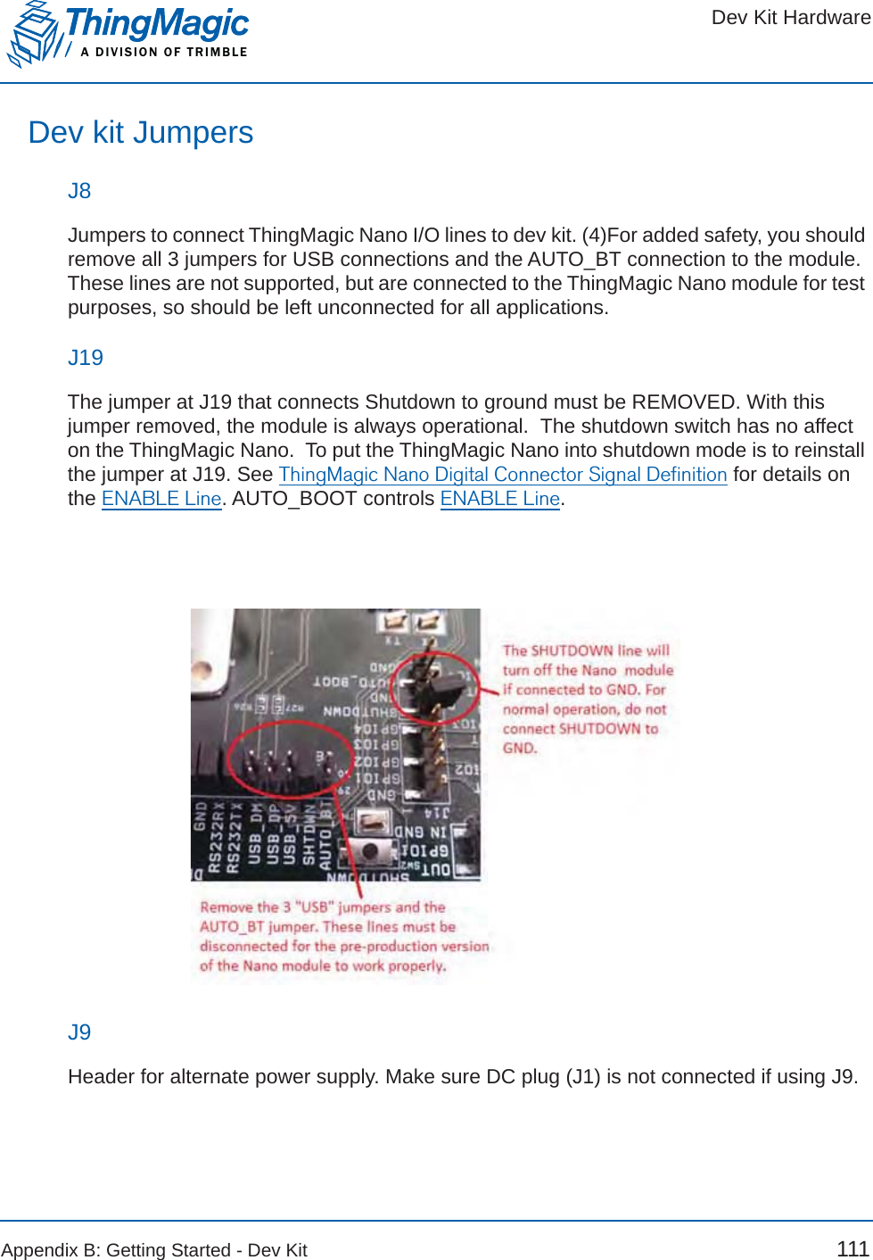
User Manual Nano Design Guide v01RevA.pdf
Navigation menu
Upload a User Manual
Namespaces
Wiki Guide
HTML
PDF
Info
Views
User Manual
Discussion / Help
Navigation


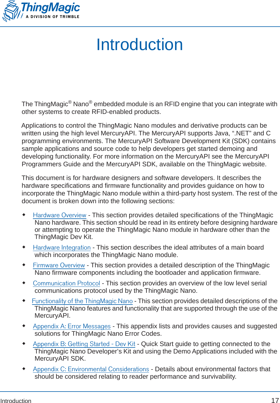
![Authorized AntennasA DIVISION OF TRIMBLE40 Hardware OverviewAuthorized AntennasThis device has been designed to operate with the antennas listed below, and having a maxi-mum gain of 8.15¬dBiL. Antennas not included in this list or having a gain greater than 8.15 dBiL¬arestrictly prohibited for use with this device without regulatory approval. The required antenna impedance is 50 ohms.ThingMagic Nano Authorized AntennasFCC Modular Certification ConsiderationsTrimble has obtained FCC modular certification for the ThingMagic Nano module. This means that the module can be installed in different end-use products by another equipment manufacturer with limited or no additional testing or equipment authorization for the transmitter function provided by that specific module. Specifically:No additional transmitter-compliance testing is required if the module is operated with one of the antennas listed in the FCC filingNo additional transmitter-compliance testing is required if the module is operated with the same type of antenna as listed in the FCC filing as long as it has equal or lower gain than the antenna listed. Equivalent antennas must be of the same general type (e.g. dipole, circularly polarized patch, etc.), must be of equal or less gain than an antenna previously authorized under the same FCC ID, and must have similar in Vendor Model Type PolarizationFrequencyRange CircularGain(dBiC)Max Linear Gain (dBi)MTIWirelessMT-263020 Patch Circular 902-928 MHz11 min 8Laird S9025P Patch Circular 902-928 MHz5.5 4.3Laird S8658WPL Patch Circular 865-960 MHz8.5 6.0MTIWirelessMTI-262013 Patch Circular 902-928 MHz7 min, 7.5 max6.0MTIWirelessMTI-242043 Patch Circular 865-956 MHz7.5 in EU band, 8.5 in NA band6.0Laird FG9026 Dipole Linear 902-928 MHz[NotApplicable]8.15Note: Most of these are circularly polarized antennas, but since most tag antennas are linearly polarized, the equivalent linear gain, as provided, of the antenna should be used for all calculations.](https://usermanual.wiki/JADAK-a-business-unit-of-Novanta/MERCURY6EN/User-Guide-2598678-Page-40.png)


![Tag Read Meta DataA DIVISION OF TRIMBLE82 Functionality of the ThingMagic NanoTag Read Meta DataIn addition to the tag EPC ID resulting from ThingMagic Nano inventory operation each TagReadData (see MercuryAPI for code details) contains meta data about how, where and when the tag was read. The specific meta data available for each tag read is as follows:Meta Data Field DescriptionAntenna ID The antenna on with the tag was read. When Using a Multi-plexer, if appropriately configured, the Antenna ID entry will contain the logical antenna port of the tag read. If the same tag is read on more than one antenna there will be a tag buffer entry for each antenna on which the tag was read. Read Count The number of times the tag was read on [Antenna ID]. Timestamp The time the tag was read, relative to the time the command to read was issued, in milliseconds. If the Tag Read Meta Data is not retrieved from the Tag Buffer between read commands there will be no way to distinguish order of tags read with dif-ferent read command invocations. Tag Data When reading an embedded TagOp is specified for a Read-Plan the TagReadData will contain the first 128 words of data returned for each tag. Note: Tags with the same TagID but different Tag Data can be considered unique and each get a Tag Buffer entry if set in the reader configuration parameter /reader/tagReadData/uniqueByData. By default it is not.Frequency The frequency on which the tag was readTag Phase Not supported in ThingMagic NanoLQI/RSSI The receive signal strength of the tag response in dBm.GPIO Status The signal status (High or Low) of all GPIO pins when tag was read.](https://usermanual.wiki/JADAK-a-business-unit-of-Novanta/MERCURY6EN/User-Guide-2598678-Page-82.png)
![Dev Kit HardwareA DIVISION OF TRIMBLE112 Appendix B: Getting Started - Dev KitJ10, J11Jump pins OUT to GPIO# to connect ThingMagic Nano GPIO lines to output LEDs. Jump pins IN to GPIO# to connect ThingMagic Nano GPIO to corresponding input switches SW[3,4]GPIO#. Make sure GPIO lines are correspondingly configured as input or outputs (see Configuring GPIO Settings).J13, J15Not used.J14Can be used to connect GPIO lines to external circuits. If used jumpers should be removed from J10, J11.J16Jump pins 1 and 2 or 2 and 3 to reset dev kit power supply. Same as using switch SW1 except allows for control by external circuit.J17Jump pins 1 and 2 to use the 5V INPUT and GND inputs to provide power. Jump pins 2 and 3 to use the Dev Kit’s DC power jack and power brick power.Dev Kit SchematicsAvailable upon request from support@thingmagic.com.](https://usermanual.wiki/JADAK-a-business-unit-of-Novanta/MERCURY6EN/User-Guide-2598678-Page-112.png)