JAPAN REMOTE CONTROL RG411BL Radio Control Receiver User Manual RG411B manual ai
JAPAN REMOTE CONTROL CO., LTD. Radio Control Receiver RG411B manual ai
User Manual
WARNING
DO NOT bend the Sleeve Antenna !
DMSS 2.4GHz 4ch Receiver
(Sleeve antenna type, supporting bi-directional communications)
Designed for Park Flight
*Note that DMSS system are not compatible with DSM-2 nor DSM-J systems.
2.4GHz Band Characteristics and Receiving Radio Wave EZ BIND System Telemetry System
Troubleshooting
Operation Manual
Receiver Specs
RG411BL
DMSS system
4.3g
35.5×18×9㎜
4.8V
4.5-8.5V
Sleeve Antenna
Configuration
●
RG411BL Receiver Main Unit
●
Operation Manual (This document)
If, after completion of binding, the receiver is turned on first...
[EZ BIND System] is a unique system designed for the
receiver of the Park Flight. With the EZ BIND System,
binding can be carried out without using a binding plug.
Binding Method
SENSOR
・ Is the remaining battery power of the transmitter and receiver adequate?
・
Has your receiver model been changed?
When the receiver does not operate, check the following points.
When the binding does not complete successfully, check the following points.
DATA : RG411BL_manual rev.B
DATE : 2014.02.06
PRINT : SANEI
Make sure to set fail safe after completion of the binding
[About the TL Logo] [About the EZ BIND Logo]
This logo is only included on
products that incorporate JR
EZ BIND System.
Thank you for purchasing JR product.
To allow correct and safe use of this product, be certain to
read this operation manual.
Brown Red
Orange
Turn the receiver ON while the transmitter is on the status of the
step 2. After a few seconds, the binding will start and the LED begins
to flash. When the LED stops blinking,
the binding operation
has been completed.
Make sure to turn on the [transmitter] first after completion of the binding
Features
・DMSS system is not interfered by cross modulation nor
intermodulation.
・A telemetry system is capable of feeding back information such
as the aircraft remaining battery power.
・It is possible to confirm the receiving condition by status LED.
・Support is provided for the fail safe settings in the transmitter.
・EZ BIND System is integrated (no binding plug is needed).
This logo is only included on
products that support the JR
Telemetry System
(bi-directional
Product Number:
Receiving System:
Weight:
Dimensions:
Rated Voltage:
Operating Voltage:
Remarks:
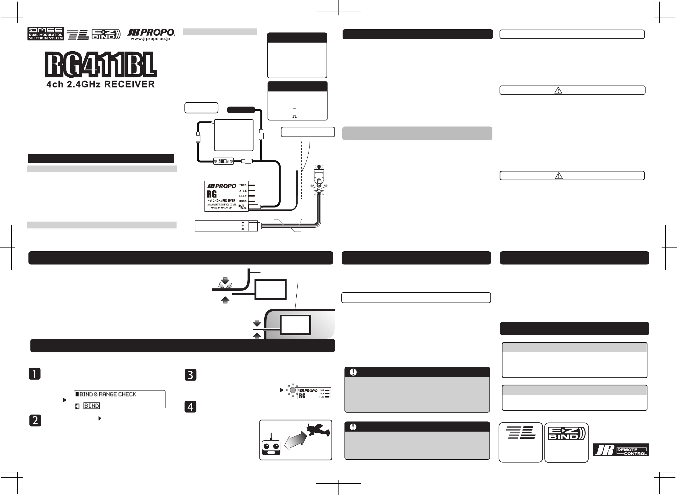
Receiver Battery
(Sold separately)
Sensor
(Sold separately)
Connection
Diagram
Switch Harness
(Sold separately)
Y-Harness
(Sold separately)
Sensor Connections
For connecting the sensor,
connect the Y-Harness
(sold separately) to the
[BIND/BATT/SENS] terminal.
* It will not be necessary to
carry out binding for the
sensor.
Japan Remote Control Co., Ltd.
■
In order to establish communications with the transmitter, binding (pairing) must certainly be carried out. In this section, an explanation is given of the binding.
Display the [BIND] Setting Screen in the transmitter System
Setting Mode. * The figure below shows the XG8 screenshot.
[Situation of the XG8]
Binding Setting
Screen
・ Is the remaining battery power of the transmitter and receiver adequate?
・ Is the distance between the transmitter and receiver too close?
・ When the procedure is carried out on the top of a desk or bench that is
made from metal, binding may not be successful.
LED Lighting Locations
Keep approximately 40m
away from the aircraft
Range Test
Next, match the cursor [ ] to BIND displayed on the
Binding Setting Screen of the transmitter and press the dial.
Following diagram shows display on XG8.
Operate the servo and confirm that the binding have been
successfully completed. Note that when carrying out a range test, after
setting the transmitter to the
reduced power output condition,
maintain a distance of approximately
40 m from the aircraft and move
around it to confirm that operation
can be carried out from all directions.
* To reduce the transmitter power output,
please read the transmitter operation
manual.
After completing a binding operation of the transmitter and
receiver, turning on the receiver first will lead it to Binding
Standby Condition in [three seconds]. The Binding Standby
Condition will last for [five seconds].
*Turning on the transmitter first will start normal
transmission operation.
*If you have changed your receiver model. Please carry out
another binding to establish new communication.
While your receiver is on Binding Standby Condition based
on the EZ BIND function, if another transmitter located
nearby starts a binding operation, binding information of
your receiver could be overwritten. To avoid such a
significant risk, make sure to turn on your transmission first.
After binding is completed, make sure to set fail safe
using the Fail Safe function on the transmitter, and
check to see if the fail safe works properly.
The Telemetry System (bi-directional communication system) is
pre-installed on RG411B, and voltage information of a receiver
battery is transmitted to the transmitter. By adding a sensor which is
optionally provided, other information including temperature and
rotational speed can be communicated.
Such information that can be displayed differs depending on a type
of transmitter you use. Before installing an additional sensor, check
functions of your transmitter.
In the situation where the antenna has been attached
directly to a shielding material such as carbon or metal,
the receiving sensitivity of the installed antenna surface
will be considerably reduced. When the antenna is to
be installed on this kind of shielding material itself,
either separate the antenna as far as possible from the
material , or in the case where the radio wave shielding
material is the aircraft body itself project the antenna
outside the aircraft body.
411BL
RX
RX
Receiving Sensitivity (Low)
Receiving Sensitivity (High)
Take care not to damage the
Sleeve antenna projecting
from the aircraft body.
Aircraft Body made from
shielding material
About Harness Connections
Connect the harnesses with
appropriate directions.
A brown cable should be on
the side of [ ] and an
orange cable should be on
the side of [ ].
RG411BL
RG411BL
In order to protect against injury to users or third parties, or damage to
property, points that must certainly be observed are shown below.
■Please Read Before Use
To allow safe use, be certain to observe the following points.
●Basic Precautions for Safe Use of the 2.4GHz System
(1) The 2.4GHz band is not a frequency exclusively for use with RC airplanes. This
frequency band is in common use with the ISM (industry, science, and medical
care) band which is widely used for short-distance transmissions such as
microwave ovens, wireless LAN, digital cordless phones, audio, gaming
devices, cell phone Bluetooth. Therefore, the response of the 2.4GHz system
may be reduced in urban areas. Further, as it also is used for ham and local area
radio communication for mobile identification, please pay attention to the
possible influences from these. In the event of any adverse radio wave
interference on an existing wireless station, immediately stop emitting radio
waves and take the interference avoidance measures.
(2) At race tracks and airfields, minimize the use of devices that can affect the
transmitter/receiver and be sure to confirm the safety beforehand. Also, always
follow the instructions of the facility staff.
(3) If an aircraft is allowed to pass behind a building, pylon, trees, etc. the
radio-wave range is blocked, the response may drop, even result in losing
control. Always let aircraft run or fly within a range that you can visually
observe.
This device complies with Part 15 of the FCC Rules. Operation is subject to the following two conditions:
(1) this device may not cause harmful interference, and (2) this device must accept any interference received,
including interference that may cause undesired operation.
Warning: Changes or modifications to this unit not expressly approved by the party responsible for compliance
could void the user's authority to operate the equipment.
NOTE: This equipment has been tested and found to comply with the limits for a Class B digital device, pursuant
to Part 15 of the FCC Rules. These limits are designed to provide reasonable protection against harmful
interference in a residential installation. This equipment generates, uses and can radiate radio frequency energy
and, if not installed and used in accordance with the instructions, may cause harmful interference to radio
communications.
However, there is no guarantee that interference will not occur in a particular installation. If this equipment does
cause harmful interference to radio or television reception, which can be determined by turning the equipment
off and on, the user is encouraged to try to correct the interference by one or more of the following measures:
1. Reorient or relocate the receiving antenna.
2. Increase the separation between the equipment and receiver.
3. Connect the equipment into an outlet on a circuit different from that to which the receiver is connected.
4. Consult the dealer or an experienced radio/TV technician for help.
This device complies with Industry Canada Licence-exempt RSS-210. Operation is subject to the following two
conditions: (1) this device may not cause interference, and (2) this device must accept any interference,
including interference that may cause undesired operation of the device.
DANGER!
WARNING!
CAUTION!
Not following this advice carries high risk of death or serious injury to
the user or third parties.
Not following this advice may result in death or serious injury the user
or third parties.
● Do not use this product in the rain as water may cause electronic devices to malfunction.
● This product carries a risk of injury due to heat, fire, and electric shock.
● Never disassemble or modify this product.
● When turning on the receiver, the engine (or motor) can start rotating at high speed,
causing injury.
● Before turning on, always set the transmitter throttle stick to the lowest speed position.
Turn on the transmitter first then the receiver.
To shut down, switch off the receiver first and then the transmitter.
Not following this advice may cause injury to the user or third party (or
cause damage to property).
■If you have further questions, please contact your local dealer or JR distributor in your country.
●Is there enough battery voltage for both the transmitter and receiver?
●Is there any fuel spillage on the receiver, servos, etc. that was caused by leakage from the fuel
tank? Is there enough fuel?
●Check that no linkage interferes with the aircraft body. Conduct a vibration test by restraining
the model and setting the engine (or motor) to full power whilst keeping your hands well
clear of the propeller. Check that each control surface moves correctly. For the initial flights of
a new model always fly in a safe place, avoid flying at great distance, and keep the model
close to the landing area for several minutes until you are fully confident that the receiver is
operating correctly.
● Do not use this receiver in combination with other manufacturers products such as servos,
gyros etc.
● Never allow the receiver to receive a strong impact as the electronic components in the
receiver are susceptible to damage.
● If degraded servo movement is detected, stop operating immediately. Identify the source
of the problem before further operation (check battery voltage, etc).
● Do not use the product in the following locations, as there will be a risk of an out-of-control
condition or accident:
• Where interference exists. • Where there is traffic passing nearby.
• Near high-tension electric lines, buildings, or in mountainous areas, etc.
• Near houses or people. • Near radio or TV transmitters
● If the receiver becomes submerged in water, it may appear to operate normally after being
fully dried. However, it may malfunction at a later time. Do not continue to use the product
‒ contact your JR distributor to arrange an inspection.
411BL