JBL Application Guidex Software Guide 3500 Ag
Application Software Guide 3500-ag USR :: USR3500 M2M 3G Cellular Modem
User Manual: JBL Application Software Guide USR :: Product
Open the PDF directly: View PDF ![]() .
.
Page Count: 224 [warning: Documents this large are best viewed by clicking the View PDF Link!]
Courier M2M 3G Cellular Modem
USR3500
Application Guide
R24.0794.00(
ii
Revision History
Date
Reason For Changes
Version
1/28/14
Initial Release
1.0
2/25/14
Cosmetic updates
1.1
Copyright
© 2014 USRobotics. All rights reserved.
Trademarks
USRobotics®, CourierTM and the USRobotics logo are registered trademarks of
U.S. Robotics Corporation.
Contact Information
Web:
http://www.usr.com/contact
Consult our website for up-to-date product descriptions, documentation, application
notes, firmware upgrades, and troubleshooting tips: http://www.usr.com/support/3500

iii
1!OVERVIEW ............................................................................................................................................................ 13!
1.1!DEFINITIONS ..................................................................................................................................................... 13!
1.2!DESIGN PRINCIPLES .......................................................................................................................................... 13!
2!NETWORK CONFIGURATIONS ........................................................................................................................... 14!
2.1!PRIVATE IP WITH VPN ....................................................................................................................................... 14!
2.2!PRIVATE IP ....................................................................................................................................................... 15!
!Mobile Originated .................................................................................................................................... 15!2.2.1
!Mobile Originated with SMS wake up (Server initiated) ......................................................................... 15!2.2.2
2.3!PUBLIC IP BASED ............................................................................................................................................... 16!
2.4!STATIC VS DYNAMIC IP ADDRESSES .................................................................................................................... 17!
2.5!CONNECTION METHODOLOGY ............................................................................................................................. 18!
2.6!DATA CONNECTION ........................................................................................................................................... 18!
3!NVM QUEUE .......................................................................................................................................................... 19!
4!PROTOCOL OVERVIEW ....................................................................................................................................... 19!
4.1!PROTOCOL ....................................................................................................................................................... 19!
4.2!ASCII FORMAT ................................................................................................................................................. 19!
4.3!ASCII COMMAND/RESPONSE TYPES ................................................................................................................... 21!
5!STRING TOKENS .................................................................................................................................................. 24!
5.1!STRINGSEND EVENTS .................................................................................................................................... 26!
5.2!AT$STRINGTOKENS ..................................................................................................................................... 27!
!Action Command .................................................................................................................................... 27!5.2.1
!Read Command ...................................................................................................................................... 27!5.2.2
5.3!AT$STRINGTEST .......................................................................................................................................... 27!
!Action Command .................................................................................................................................... 28!5.3.1
!Example .................................................................................................................................................. 28!5.3.2
5.4!AT$STRINGSENDEMAIL ............................................................................................................................... 28!
!Action Command .................................................................................................................................... 28!5.4.1
!Read Command ...................................................................................................................................... 29!5.4.2
!Example .................................................................................................................................................. 30!5.4.3
5.5!AT$STRINGSENDSMS .................................................................................................................................. 31!
!Action Command .................................................................................................................................... 31!5.5.1
!Read Command ...................................................................................................................................... 32!5.5.2
!Example .................................................................................................................................................. 33!5.5.3
5.6!AT$STRINGSEND .......................................................................................................................................... 33!
!Action Command .................................................................................................................................... 33!5.6.1
!Read Command ...................................................................................................................................... 34!5.6.2
!Example 1: Send Email ......................................................................................................................... 35!5.6.3
!Example 2: Serial to TCP Endpoint Connection .................................................................................... 35!5.6.4
6!SYSTEM VARIABLES ........................................................................................................................................... 37!
6.1!VARIABLE IDENTIFIERS ....................................................................................................................................... 37!
6.2!STRING TOKENS ................................................................................................................................................ 37!
6.3!EVENTS ............................................................................................................................................................ 37!
6.4!LIST OF STATUS VARIABLES ............................................................................................................................... 38!
6.5!AT$VARIABLESTATUS ................................................................................................................................. 39!
!Read Command ...................................................................................................................................... 39!6.5.1
6.6!AT$VARIABLETHRESHOLD ......................................................................................................................... 40!
!Set Command ......................................................................................................................................... 40!6.6.1
!Delete Command .................................................................................................................................... 40!6.6.2
!Read Command ...................................................................................................................................... 40!6.6.3
!Example .................................................................................................................................................. 41!6.6.4
6.7!AT$VARIABLECOMPARE ............................................................................................................................. 41!
!Set Command ......................................................................................................................................... 42!6.7.1
!Delete Command .................................................................................................................................... 42!6.7.2

iv
!Read Command ...................................................................................................................................... 42!6.7.3
!Example .................................................................................................................................................. 43!6.7.4
6.8!AT$VARIABLESET ........................................................................................................................................ 43!
!Set Command ......................................................................................................................................... 43!6.8.1
!Delete Command .................................................................................................................................... 43!6.8.2
!Read Command ...................................................................................................................................... 44!6.8.3
!Example .................................................................................................................................................. 45!6.8.4
6.9!AT$VARIABLESEND ..................................................................................................................................... 45!
!Set Command ......................................................................................................................................... 45!6.9.1
!Delete Command .................................................................................................................................... 46!6.9.2
!Read Command ...................................................................................................................................... 46!6.9.3
!Example .................................................................................................................................................. 47!6.9.4
7!EVENTS ................................................................................................................................................................. 47!
7.1!EVENT TYPES ................................................................................................................................................... 48!
7.2!EVENT LABELS .................................................................................................................................................. 50!
7.3!SYSTEM EVENTS ............................................................................................................................................... 50!
7.4!EVENT LABEL COMMAND .................................................................................................................................... 51!
!AT$EVENTLABEL .................................................................................................................................. 51!7.4.1
7.5!EVENT DISPLAY COMMAND ................................................................................................................................ 52!
!AT$EVENTDISPLAY .............................................................................................................................. 52!7.5.1
Action command ............................................................................................................................................. 52!
Read command .............................................................................................................................................. 53!
Unsolicited response ...................................................................................................................................... 53!
7.6!EVENT FILTERS ................................................................................................................................................. 53!
7.7!EVENTS ............................................................................................................................................................ 53!
!AT$EVENTFILTER ................................................................................................................................. 54!7.7.1
Action Command ............................................................................................................................................ 54!
Read Command .............................................................................................................................................. 54!
Example .......................................................................................................................................................... 54!
7.8!EVENT SEQUENCES ........................................................................................................................................... 55!
7.9!EVENTS ............................................................................................................................................................ 55!
!AT$EVENTSEQUENCE ......................................................................................................................... 55!7.9.1
Action Command ............................................................................................................................................ 56!
Read Command .............................................................................................................................................. 56!
Example .......................................................................................................................................................... 57!
7.10!AT$EVENTGEN ........................................................................................................................................... 57!
8!POWER MANAGEMENT ....................................................................................................................................... 58!
8.1!EVENTS ............................................................................................................................................................ 58!
8.2!STRING TOKENS ................................................................................................................................................ 58!
8.3!AT$LOWPOWERON ...................................................................................................................................... 59!
!Action Command .................................................................................................................................... 59!8.3.1
!Delete Configuration ............................................................................................................................... 59!8.3.2
!Read Command ...................................................................................................................................... 59!8.3.3
!Example .................................................................................................................................................. 60!8.3.4
8.4!AT$LOWPOWEROFF .................................................................................................................................... 60!
!Action Command .................................................................................................................................... 60!8.4.1
!Delete Configuration ............................................................................................................................... 60!8.4.2
!Immediate Disable .................................................................................................................................. 61!8.4.3
!Read Command ...................................................................................................................................... 61!8.4.4
!Example .................................................................................................................................................. 61!8.4.5
9!IDENTIFICATION COMMANDS ............................................................................................................................ 63!
9.1!EVENTS ............................................................................................................................................................ 63!
9.2!STRING TOKENS ................................................................................................................................................ 63!
9.3!GET APPLICATION VERSION COMMAND ............................................................................................................... 64!
!AT$APPVERSION .................................................................................................................................. 64!9.3.1
Read Command .............................................................................................................................................. 64!

v
9.4!GET FIRMWARE VERSION COMMAND ................................................................................................................... 64!
!AT$FWVERSION ................................................................................................................................... 65!9.4.1
9.5!GET MODEM ID COMMAND ................................................................................................................................. 65!
!AT$MODEMID ........................................................................................................................................ 65!9.5.1
Read Command .............................................................................................................................................. 65!
9.6!GET SUBSCRIBER ID COMMAND ......................................................................................................................... 66!
!AT$SUBSCRIBERID .............................................................................................................................. 66!9.6.1
Read Command .............................................................................................................................................. 66!
9.7!DEVICE IDENTIFICATION ..................................................................................................................................... 66!
!AT$DEVICEID ........................................................................................................................................ 67!9.7.1
Action Command/Response ........................................................................................................................... 67!
Read Command/Response ............................................................................................................................ 67!
9.8!GET BUILD FEATURES ........................................................................................................................................ 67!
!AT$FEATURE ........................................................................................................................................ 68!9.8.1
Read Command .............................................................................................................................................. 68!
10!TIME ..................................................................................................................................................................... 69!
10.1!EVENTS .......................................................................................................................................................... 69!
10.2!STRING TOKENS .............................................................................................................................................. 69!
!Using a Stored Timestamp ................................................................................................................... 70!10.2.1
Example .......................................................................................................................................................... 70!
10.3!MANUALLY SET AND GET DEVICE CLOCK ........................................................................................................... 71!
!AT$TIME ............................................................................................................................................... 71!10.3.1
Action Command/Response ........................................................................................................................... 71!
Read Command/Response ............................................................................................................................ 71!
10.4!AUTOMATICALLY SET DEVICE CLOCK ................................................................................................................ 72!
!AT$AUTOTIME ..................................................................................................................................... 72!10.4.1
Action Command/Response ........................................................................................................................... 72!
Read Command/Response ............................................................................................................................ 72!
10.5!TIMERS ........................................................................................................................................................... 73!
!Timer Events ......................................................................................................................................... 73!10.5.1
!AT$TIMERSTART ................................................................................................................................ 73!10.5.2
Action Command ............................................................................................................................................ 73!
Restart Timer .................................................................................................................................................. 74!
Delete Timer ................................................................................................................................................... 74!
Read Command .............................................................................................................................................. 74!
Unsolicited Response ..................................................................................................................................... 74!
Example .......................................................................................................................................................... 75!
!AT$TIMERSTOP .................................................................................................................................. 75!10.5.3
Action Command ............................................................................................................................................ 75!
Delete Timer ................................................................................................................................................... 75!
Read Command .............................................................................................................................................. 76!
Example .......................................................................................................................................................... 76!
!Watchdog Examples ............................................................................................................................. 76!10.5.4
Server Connection Watchdog ......................................................................................................................... 76!
TCP Server Data Watchdog ........................................................................................................................... 77!
Serial Endpoint Data Watchdog ...................................................................................................................... 77!
10.6!ALARM CLOCK ................................................................................................................................................ 78!
!Alarm Clock Events .............................................................................................................................. 78!10.6.1
!AT$ALARMCLOCK .............................................................................................................................. 78!10.6.2
Action command ............................................................................................................................................. 78!
Read command .............................................................................................................................................. 79!
11!DEVICE CONFIGURATION ................................................................................................................................. 80!
11.1!SYSTEM VARIABLES ......................................................................................................................................... 80!
11.2!STRING TOKENS .............................................................................................................................................. 80!
11.3!SIGNAL QUALITY ............................................................................................................................................. 80!
!AT$CSQ ............................................................................................................................................... 80!11.3.1
Test command ................................................................................................................................................ 80!

vi
Action command ............................................................................................................................................. 80!
Parameter command ...................................................................................................................................... 81!
Read command .............................................................................................................................................. 81!
11.4!SMS FORWARDING BEHAVIOR ......................................................................................................................... 81!
!AT$SMSFORWARD ............................................................................................................................. 81!11.4.1
Action Command ............................................................................................................................................ 81!
Read Command .............................................................................................................................................. 82!
11.5!DEVICE RESET ................................................................................................................................................ 82!
!AT$RESET ........................................................................................................................................... 82!11.5.1
Action Command ............................................................................................................................................ 83!
Read command .............................................................................................................................................. 83!
Example .......................................................................................................................................................... 83!
11.6!DEVICE SHUTOFF ......................................................................................................................................... 84!
!AT$SHUTOFF ...................................................................................................................................... 84!11.6.1
11.7!DEVICE EVENT REPORTING .............................................................................................................................. 84!
!AT$REPORT ........................................................................................................................................ 85!11.7.1
Action Command ............................................................................................................................................ 85!
Read Command .............................................................................................................................................. 85!
!Unsolicited $REPORT .......................................................................................................................... 85!11.7.2
Unsolicited Response ..................................................................................................................................... 85!
12!CELLULAR COMMUNICATIONS ....................................................................................................................... 86!
12.1!GPRS EVENTS ............................................................................................................................................... 86!
12.2!STRING TOKENS .............................................................................................................................................. 87!
12.3!GPRS SETTINGS ............................................................................................................................................. 87!
!AT$CGDCONT ..................................................................................................................................... 87!12.3.1
Action Command ............................................................................................................................................ 87!
Delete Command ............................................................................................................................................ 88!
Read Command .............................................................................................................................................. 88!
12.4!NETWORK IP .................................................................................................................................................. 89!
!AT$IP .................................................................................................................................................... 89!12.4.1
Read Command .............................................................................................................................................. 89!
Parameters ..................................................................................................................................................... 89!
12.5!PING .............................................................................................................................................................. 89!
!AT$PING .............................................................................................................................................. 90!12.5.1
Action Command ............................................................................................................................................ 90!
Unsolicited Response ..................................................................................................................................... 90!
13!ETHERNET .......................................................................................................................................................... 91!
13.1!EVENTS .......................................................................................................................................................... 91!
13.2!SYSTEM VARIABLES ......................................................................................................................................... 91!
13.3!STRING TOKENS .............................................................................................................................................. 91!
13.4!ETHERNET INTERFACE ..................................................................................................................................... 91!
!AT$ENABLEETHERNET ...................................................................................................................... 92!13.4.1
Action Command ............................................................................................................................................ 92!
Read Command .............................................................................................................................................. 92!
13.5!ETHERNET IP .................................................................................................................................................. 93!
!GETETHERNETIP ................................................................................................................................ 93!13.5.1
!AT$ETHERNETIP ................................................................................................................................ 93!13.5.2
Read Command .............................................................................................................................................. 93!
13.6!DHCP SERVER ............................................................................................................................................... 94!
!AT$DHCPS ........................................................................................................................................... 94!13.6.1
Action Command ............................................................................................................................................ 94!
Read Command .............................................................................................................................................. 94!
!AT$DHCPDNS ..................................................................................................................................... 95!13.6.2
Action command ............................................................................................................................................. 95!
Read command .............................................................................................................................................. 95!
13.7!STATIC IP ADDRESS ........................................................................................................................................ 96!
!AT$STATICIP ....................................................................................................................................... 96!13.7.1

vii
Action Command ............................................................................................................................................ 96!
Read Command .............................................................................................................................................. 96!
13.8!NETWORK ADDRESS TRANSLATION (NAT) ......................................................................................................... 97!
!AT$NAT ................................................................................................................................................ 97!13.8.1
Action Command ............................................................................................................................................ 97!
Read Command .............................................................................................................................................. 97!
13.9!PORT FORWARDING ......................................................................................................................................... 98!
!AT$PORTFORWARD ........................................................................................................................... 98!13.9.1
Action Command ............................................................................................................................................ 98!
Read Command .............................................................................................................................................. 98!
13.10!EXAMPLE: HOW TO SETUP AN ETHERNET BRIDGE ............................................................................................. 99!
14!REMOTE AT COMMAND SUPPORT ................................................................................................................ 101!
14.1!TELNET PORT SETTINGS .............................................................................................................................. 101!
!System Variables ................................................................................................................................ 101!14.1.1
!String Tokens ...................................................................................................................................... 101!14.1.2
!Telnet Port Events .............................................................................................................................. 102!14.1.3
!AT$TELNETPORT ............................................................................................................................. 102!14.1.4
Action Command .......................................................................................................................................... 102!
Read Command ............................................................................................................................................ 102!
Example ........................................................................................................................................................ 103!
14.2!SMS COMMAND INTERFACE ........................................................................................................................... 104!
!AT$SMS ............................................................................................................................................. 104!14.2.1
Action Command .......................................................................................................................................... 104!
Read Command ............................................................................................................................................ 105!
Example ........................................................................................................................................................ 106!
15!ENDPOINT / BRIDGE: “PASS THROUGH” ROUTING SUPPORT ................................................................. 106!
15.1!EVENTS ........................................................................................................................................................ 107!
!Serial Endpoint Events ....................................................................................................................... 107!15.1.1
!TCP/UDP Endpoint Events ................................................................................................................. 108!15.1.2
15.2!SYSTEM VARIABLES ....................................................................................................................................... 108!
15.3!STRING TOKENS ............................................................................................................................................ 109!
15.4!ENDPOINT SETTINGS ...................................................................................................................................... 109!
!AT$ENDPOINT ................................................................................................................................... 110!15.4.1
Action Command .......................................................................................................................................... 110!
Read Command ............................................................................................................................................ 111!
!Examples ............................................................................................................................................ 114!15.4.2
15.5!BRIDGE (ROUTE) SETTINGS ............................................................................................................................. 115!
!Bridge Events ..................................................................................................................................... 115!15.5.1
!AT$BRIDGECREATE ......................................................................................................................... 116!15.5.2
Action Command .......................................................................................................................................... 116!
Immediate Command ................................................................................................................................... 116!
Delete Command .......................................................................................................................................... 116!
Read Command ............................................................................................................................................ 117!
!AT$BRIDGEDELETE ......................................................................................................................... 118!15.5.3
Action Command .......................................................................................................................................... 118!
Delete Command .......................................................................................................................................... 118!
Read Command ............................................................................................................................................ 118!
15.6!ENDPOINT SERVER ........................................................................................................................................ 119!
!AT$ESERVER .................................................................................................................................... 119!15.6.1
Action Command .......................................................................................................................................... 119!
Read Command ............................................................................................................................................ 119!
15.7!ONLINE DATA MODE ...................................................................................................................................... 120!
!AT$ONLINE ........................................................................................................................................ 121!15.7.1
15.8!FILTERING ENDPOINTS ................................................................................................................................... 121!
!Strip ETX/DLE .................................................................................................................................... 122!15.8.1
Example ........................................................................................................................................................ 122!
!Compress/Decompress ...................................................................................................................... 123!15.8.2

viii
Example 1 ..................................................................................................................................................... 123!
Example 2 ..................................................................................................................................................... 124!
16!AT PARSER ENDPOINTS ................................................................................................................................. 125!
16.1!EVENTS ........................................................................................................................................................ 125!
16.2!ASCII COMMANDS ........................................................................................................................................ 125!
!Action Command ................................................................................................................................ 125!16.2.1
!Read Command .................................................................................................................................. 126!16.2.2
!Example .............................................................................................................................................. 127!16.2.3
17!SMS ENDPOINTS ............................................................................................................................................. 127!
17.1!ENDPOINT CONFIGURATION ............................................................................................................................ 128!
17.2!EVENTS ........................................................................................................................................................ 128!
17.3!ASCII COMMANDS ........................................................................................................................................ 128!
!Action Command ................................................................................................................................ 128!17.3.1
!Read Command .................................................................................................................................. 129!17.3.2
18!FTP ENDPOINTS ............................................................................................................................................... 131!
18.1!CONFIGURATIONS .......................................................................................................................................... 131!
18.2!EVENTS ........................................................................................................................................................ 131!
!FTP GET ............................................................................................................................................. 131!18.2.1
!FTP PUT ............................................................................................................................................. 132!18.2.2
18.3!ASCII COMMANDS ........................................................................................................................................ 132!
!Action Command ................................................................................................................................ 132!18.3.1
!Read Command .................................................................................................................................. 133!18.3.2
18.4!GET EXAMPLE .............................................................................................................................................. 134!
18.5!PUT EXAMPLE .............................................................................................................................................. 134!
19!HTTP ENDPOINTS ............................................................................................................................................ 135!
19.1!CONFIGURATIONS .......................................................................................................................................... 135!
19.2!EVENTS ........................................................................................................................................................ 135!
!HTTP GET .......................................................................................................................................... 135!19.2.1
!HTTP PUT .......................................................................................................................................... 136!19.2.2
!HTTP POST ........................................................................................................................................ 136!19.2.3
19.3!ASCII COMMANDS ........................................................................................................................................ 136!
!Action Command ................................................................................................................................ 136!19.3.1
!Read Command .................................................................................................................................. 137!19.3.2
19.4!GET EXAMPLE ............................................................................................................................................... 139!
19.5!PUT EXAMPLE ............................................................................................................................................... 140!
20!EMAIL ENDPOINTS .......................................................................................................................................... 140!
20.1!CONFIGURATIONS .......................................................................................................................................... 140!
20.2!EVENTS ........................................................................................................................................................ 141!
!POP Endpoint ..................................................................................................................................... 141!20.2.1
!SMTP Endpoint ................................................................................................................................... 141!20.2.2
20.3!AT$ENDPOINT .......................................................................................................................................... 141!
!Action Command ................................................................................................................................ 141!20.3.1
!Read Command .................................................................................................................................. 142!20.3.2
20.4!EMAIL HEADER .............................................................................................................................................. 143!
!AT$EMAILHDR ................................................................................................................................... 143!20.4.1
Action Command .......................................................................................................................................... 143!
Read Command ............................................................................................................................................ 144!
20.5!EXAMPLE ...................................................................................................................................................... 144!
21!OFFLINE DATA MODE ..................................................................................................................................... 146!
21.1!EVENTS ........................................................................................................................................................ 146!
21.2!AT$ENDPOINT .......................................................................................................................................... 146!
!Action Command ................................................................................................................................ 146!21.2.1
!Read Command .................................................................................................................................. 147!21.2.2

ix
21.3!AT$EPWRITE ............................................................................................................................................. 147!
!Action Command ................................................................................................................................ 148!21.3.1
21.4!AT$EPREAD .............................................................................................................................................. 149!
!Action Command ................................................................................................................................ 149!21.4.1
21.5!OFFLINE DATA UNSOLICITED RESPONSES: ....................................................................................................... 150!
22!FTP OPERATIONS ............................................................................................................................................ 152!
22.1!FTP COMMAND EVENTS ................................................................................................................................ 152!
22.2!FTP COMMANDS ........................................................................................................................................... 152!
22.3!AT$FTPOPEN ............................................................................................................................................ 153!
!Action Command ................................................................................................................................ 153!22.3.1
!Immediate Command ......................................................................................................................... 153!22.3.2
!Delete OPEN parameters ................................................................................................................... 153!22.3.3
!Read Command .................................................................................................................................. 154!22.3.4
!Examples ............................................................................................................................................ 154!22.3.5
22.4!AT$FTPCLOSE .......................................................................................................................................... 155!
22.5!AT$FTPMKDIR ........................................................................................................................................... 155!
!Action Command ................................................................................................................................ 155!22.5.1
!Immediate Command ......................................................................................................................... 155!22.5.2
!Delete MKDIR parameters .................................................................................................................. 155!22.5.3
!Read Command .................................................................................................................................. 156!22.5.4
!Examples ............................................................................................................................................ 156!22.5.5
22.6!AT$FTPCWD .............................................................................................................................................. 157!
22.7!AT$FTPDELDIR ......................................................................................................................................... 157!
22.8!AT$FTPDEL ............................................................................................................................................... 157!
!Action Command ................................................................................................................................ 157!22.8.1
!Immediate Command ......................................................................................................................... 158!22.8.2
!Delete DEL parameters ...................................................................................................................... 158!22.8.3
!Read Command .................................................................................................................................. 158!22.8.4
!Examples ............................................................................................................................................ 159!22.8.5
22.9!AT$FTPREN ............................................................................................................................................... 159!
!Action Command ................................................................................................................................ 159!22.9.1
!Immediate Command ......................................................................................................................... 160!22.9.2
!Delete REN parameters ...................................................................................................................... 160!22.9.3
!Read Command .................................................................................................................................. 160!22.9.4
!Examples ............................................................................................................................................ 161!22.9.5
23!SMS ALERTING ................................................................................................................................................ 161!
23.1!SMS ALERTING EVENTS ................................................................................................................................ 162!
23.2!COMMANDS .................................................................................................................................................. 162!
23.3!AT$STRINGLIST ........................................................................................................................................ 162!
!Action Command ................................................................................................................................ 162!23.3.1
!Delete ................................................................................................................................................. 162!23.3.2
!Read Command .................................................................................................................................. 162!23.3.3
!Examples ............................................................................................................................................ 163!23.3.4
23.4!AT$SENDSMSLIST .................................................................................................................................... 163!
!Action Command ................................................................................................................................ 164!23.4.1
!Immediate Command ......................................................................................................................... 164!23.4.2
!Delete ................................................................................................................................................. 164!23.4.3
!Read Command .................................................................................................................................. 164!23.4.4
!Examples ............................................................................................................................................ 165!23.4.5
24!TAG FILE SYSTEM ........................................................................................................................................... 166!
24.1!TAG EVENTS ................................................................................................................................................. 166!
24.2!SYSTEM VARIABLES ....................................................................................................................................... 167!
24.3!STRING TOKENS ............................................................................................................................................ 167!
24.4!ENDPOINT CONFIGURATION ............................................................................................................................ 167!
!Tag Endpoint Events .......................................................................................................................... 168!24.4.1
!AT$ENDPOINT ................................................................................................................................... 169!24.4.2

x
Action Command .......................................................................................................................................... 169!
Read Command ............................................................................................................................................ 169!
24.5!TAG COMMANDS ........................................................................................................................................... 171!
24.6!TAG FORMAT ................................................................................................................................................ 171!
!AT$TAGFORMAT ............................................................................................................................... 171!24.6.1
Action Command .......................................................................................................................................... 171!
24.7!TAG RECOMPACT .......................................................................................................................................... 172!
!AT$TAGRECOMPACT ....................................................................................................................... 172!24.7.1
Action Command .......................................................................................................................................... 172!
24.8!TAG INSTALL ................................................................................................................................................. 173!
!AT$TAGINSTALL ............................................................................................................................... 173!24.8.1
Action Command .......................................................................................................................................... 173!
Read Command ............................................................................................................................................ 174!
Examples ...................................................................................................................................................... 174!
24.9!TAG WRITE ................................................................................................................................................... 175!
!AT$TAGWRITE .................................................................................................................................. 175!24.9.1
Action Command .......................................................................................................................................... 175!
Example ........................................................................................................................................................ 176!
24.10!TAG CLOSE ................................................................................................................................................. 176!
!AT$TAGCLOSE ............................................................................................................................... 176!24.10.1
Action Command .......................................................................................................................................... 176!
Read Command ............................................................................................................................................ 177!
Examples ...................................................................................................................................................... 178!
24.11!TAG DELETE ............................................................................................................................................... 178!
!AT$TAGDELETE .............................................................................................................................. 178!24.11.1
Action Command .......................................................................................................................................... 178!
Read Command ............................................................................................................................................ 179!
Examples ...................................................................................................................................................... 179!
24.12!TAG READ .................................................................................................................................................. 180!
!AT$TAGREAD .................................................................................................................................. 180!24.12.1
Action Command .......................................................................................................................................... 180!
24.13!TAG SYSTEM INFORMATION .......................................................................................................................... 181!
!AT$TAGSYSINFO ............................................................................................................................ 181!24.13.1
Action Command .......................................................................................................................................... 181!
24.14!TAG LIST ALL .............................................................................................................................................. 182!
!AT$TAGLISTALL .............................................................................................................................. 182!24.14.1
Action Command .......................................................................................................................................... 182!
24.15!TAG CREATE ............................................................................................................................................... 182!
!AT$TAGCREATE ............................................................................................................................. 183!24.15.1
Action Command .......................................................................................................................................... 183!
Read Command ............................................................................................................................................ 183!
Examples ...................................................................................................................................................... 184!
24.16!TAG DOWNLOAD .......................................................................................................................................... 184!
!AT$TAGDOWNLOADFTP and AT$TAGDOWNLOADHTTP ........................................................... 185!24.16.1
Action Command .......................................................................................................................................... 185!
Read Command ............................................................................................................................................ 186!
Examples ...................................................................................................................................................... 187!
!Firmware Upgrade (FOTA) ............................................................................................................... 188!24.16.2
Example ........................................................................................................................................................ 188!
24.17!TAG UPLOAD .............................................................................................................................................. 188!
!AT$TAGUPLOADFTP and AT$TAGUPLOADHTTP ........................................................................ 189!24.17.1
Action Command .......................................................................................................................................... 189!
Read Command ............................................................................................................................................ 189!
Examples ...................................................................................................................................................... 191!
25!GPIO .................................................................................................................................................................. 191!
25.1!EVENTS ........................................................................................................................................................ 192!
25.2!STRING TOKENS ............................................................................................................................................ 192!
25.3!AT$GPIOCONFIG ...................................................................................................................................... 192!

xi
!Action Command ................................................................................................................................ 192!25.3.1
!Read Command .................................................................................................................................. 193!25.3.2
25.4!AT$GPIOREAD .......................................................................................................................................... 194!
!Action Command ................................................................................................................................ 194!25.4.1
!Read Command .................................................................................................................................. 194!25.4.2
25.5!AT$GPIOWRITE ........................................................................................................................................ 194!
!Action Command ................................................................................................................................ 194!25.5.1
!Read Command .................................................................................................................................. 195!25.5.2
25.6!AT$GPIOACTION ...................................................................................................................................... 195!
25.7!AT$GPIOACTIONMULTI ............................................................................................................................ 195!
25.8!EXAMPLES .................................................................................................................................................... 196!
26!VOICE CALL SYSTEM ...................................................................................................................................... 197!
26.1!OVERVIEW .................................................................................................................................................... 197!
26.2!EVENT IDS .................................................................................................................................................... 197!
26.3!AT$VOICECALL ......................................................................................................................................... 198!
!Action Command/Response ............................................................................................................... 198!26.3.1
!Read Command/Response ................................................................................................................ 198!26.3.2
!Test Command/Response .................................................................................................................. 198!26.3.3
!Unsolicited response .......................................................................................................................... 198!26.3.4
26.4!AT$CALLSTART ........................................................................................................................................ 199!
!Action Command/Response ............................................................................................................... 199!26.4.1
!Read Command/Response ................................................................................................................ 199!26.4.2
................................................................................................................................................................. 200!26.4.3
26.5!AT$CALLANSWER .................................................................................................................................... 200!
!Action Command/Response ............................................................................................................... 201!26.5.1
!Read Command/Response ................................................................................................................ 201!26.5.2
................................................................................................................................................................. 201!26.5.3
26.6!AT$CALLHANGUP ..................................................................................................................................... 202!
!Action Command/Response ............................................................................................................... 202!26.6.1
!Read Command/Response ................................................................................................................ 202!26.6.2
................................................................................................................................................................. 202!26.6.3
26.7!VOICE CALL EXAMPLES .................................................................................................................................. 203!
27!DTMF TONE SYSTEM ...................................................................................................................................... 205!
27.1!OVERVIEW .................................................................................................................................................... 205!
27.2!DTMF EVENT IDS ......................................................................................................................................... 205!
27.3!AT$DTMFPLAY .......................................................................................................................................... 206!
!Action Command/Response ............................................................................................................... 206!27.3.1
!Read Command/Response ................................................................................................................ 206!27.3.2
27.4!AT$DTMFDETECT ..................................................................................................................................... 207!
!Action Command/Response ............................................................................................................... 208!27.4.1
!Read Command/Response ................................................................................................................ 208!27.4.2
!Unsolicited Response ......................................................................................................................... 208!27.4.3
27.5!DTMF TONE EXAMPLES ................................................................................................................................. 209!
28!GPS TRACKING ................................................................................................................................................ 210!
28.1!OVERVIEW .................................................................................................................................................... 210!
28.2!GPS EVENTS ................................................................................................................................................ 210!
28.3!SYSTEM VARIABLES ....................................................................................................................................... 210!
!Example .............................................................................................................................................. 211!28.3.1
28.4!STRING TOKENS ............................................................................................................................................ 211!
28.5!GPS CONFIGURATION ................................................................................................................................... 212!
!AT$GPS .............................................................................................................................................. 212!28.5.1
Action Command .......................................................................................................................................... 212!
Read Command ............................................................................................................................................ 212!
28.6!LOCATION MONITORING ................................................................................................................................. 213!
!AT$LOCATE ....................................................................................................................................... 213!28.6.1
Action Command .......................................................................................................................................... 213!

xii
Read Command ............................................................................................................................................ 214!
Unsolicited Response ................................................................................................................................... 214!
28.7!EXTENDED LOCATION MONITORING ................................................................................................................. 215!
!AT$LOCATEEXT ................................................................................................................................ 215!28.7.1
Action Command .......................................................................................................................................... 215!
Read Command ............................................................................................................................................ 215!
28.8!NMEA OUTPUT ............................................................................................................................................ 216!
!AT$NMEA ........................................................................................................................................... 216!28.8.1
Action Command .......................................................................................................................................... 216!
Read Command ............................................................................................................................................ 216!
28.9!GEOFENCE CONTROL ................................................................................................................................ 217!
!AT$GEOFENCE ................................................................................................................................. 217!28.9.1
Action Command .......................................................................................................................................... 217!
Read Command ............................................................................................................................................ 218!
Unsolicited Response ................................................................................................................................... 218!
28.10!SPEED MONITORING .................................................................................................................................. 218!
!AT$SPEED ....................................................................................................................................... 219!28.10.1
Action Command .......................................................................................................................................... 219!
Read Command ............................................................................................................................................ 219!
29!CONFIGURATION SYSTEM ............................................................................................................................. 220!
29.1!OVERVIEW .................................................................................................................................................... 220!
29.2!AT$CONFIG ............................................................................................................................................... 220!
30!FIRMWARE AND SOFTWARE UPDATES ....................................................................................................... 221!
30.1!DOWNLOADING MODEM FIRMWARE .................................................................................................................. 221!
30.2!DOWNLOADING APPLICATION SOFTWARE .......................................................................................................... 221!
31!APPENDIX A – STATUS CODES ..................................................................................................................... 222!
31.1!<STATUS> PARAMETER .................................................................................................................................. 222!
31.2!STANDARD CME ERRORS .............................................................................................................................. 224!

13
1 Overview
The Courier M2M software is a platform for building robust M2M solutions that must
communicate with a server. A few of Courier M2M software’s more important features
include cellular modem control, bearer management, device management, GPS device
control, and asset tracking functionality. The purpose of this document is to describe
these features and AT command communication protocol of the Courier M2M software.
1.1 Definitions
In this document, the USR3500 executing the Courier M2M software is referred to as
the ‘device’. The remote node communicating with the device is referred to as the
‘server’.
The following table shows the acronyms used in this document and their meanings:
Abbreviation
Description
ADC
A to D Converter
APN
Access Point Name
ASCII
American Standard Code for Information
Interchange
DHCP
Dynamic Host Configuration Protocol
DNS
Domain Name System
FOTA
Firmware Upgrade Over The Air
GPRS
General Packet Radio Service
IP
Internet Protocol
NAT
Network Address Translator
NVM
Non-Volatile Memory (Flash)
PDP
Packet Data Protocol
SMS
Short Message Service
TCP
Transmission Control Protocol
UDP
User Datagram Protocol
USB
Universal Serial Bus
WD
Watchdog
1.2 Design Principles
This document is laid out to show the device interface for each individual subsystem or
feature. Within a subsystem or feature section, each “command” is defined and the
ASCII command is specified. Examples are provided as appendixes.
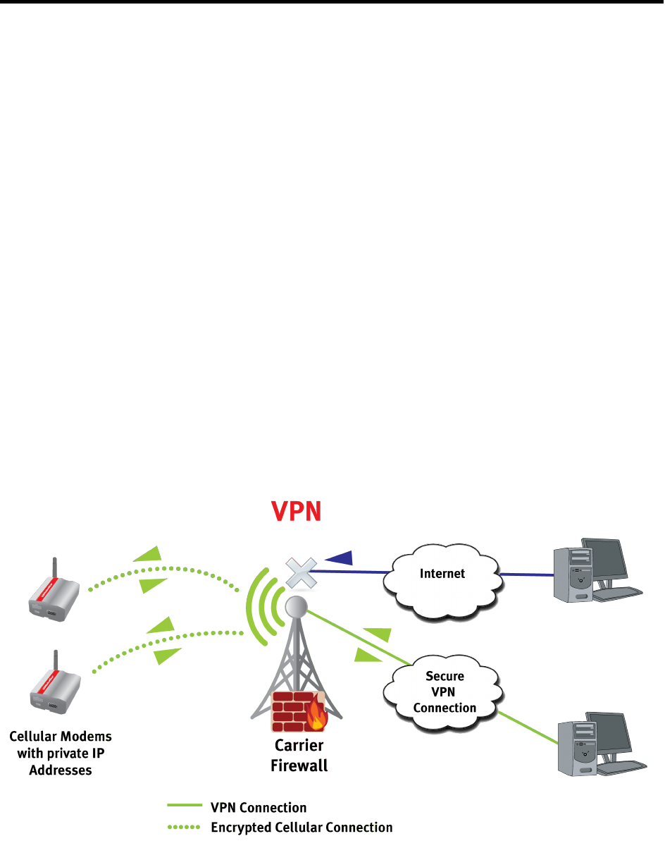
14
2 Network Configurations
Different network configurations can be used when communicating to a remote device.
The wireless provider (carrier) assigns the device an IP address when the device
connects to the wireless network’s data services. Depending on the network provider
and desired protocol, one of the following network configurations would be used:
• Private IP with Virtual Private Network (VPN)
• Private IP Network
• Public IP Network
2.1 Private IP with VPN
Network configuration used when the device is assigned a private IP address by the
carrier. The device is behind the carrier’s NAT/Firewall and thus is assigned a private IP
address, which is not accessible by a remote server. But if bidirectional UDP or mobile
terminated TCP connections are required, then a server can use a Virtual Private
Network (VPN) tunnel so it can communicate inside the firewall. This way the server and
the device would be able to access each other’s private IP addresses.
In this configuration both the device and the server can originate and terminate IP based
messages (TCP or UDP).
If your system requires the server to originate connections to the modem, and you don’t
wish to rely on SMS to initiate those connections, then this is a good option. The
remaining option is to have the server and modem use public IP addresses.
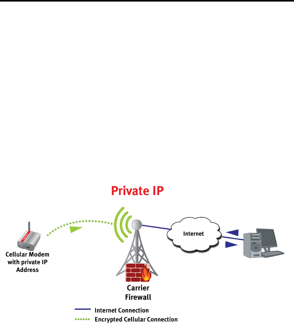
15
2.2 Private IP
Network configuration used when the server has a public IP address, but the device is
assigned a private IP address. In this configuration the device can originate any IP
based messages (TCP or UDP).
Mobile Originated 2.2.1
The device is behind the carriers NAT/Firewall and thus is assigned a private IP
address that is not accessible from the rest of the internet. In this scenario, the private
IP address would not be accessible by a remote server.
Unfortunately, the only way IP based bidirectional communications are possible is if the
modem originates a TCP connection to the server. This way the NAT will be able to
manage the TCP connection so packets coming back from the server are received by
the modem.
The following figure illustrates a mobile originated use case.
Mobile Originated with SMS wake up (Server initiated) 2.2.2
The server cannot originate TCP connections or send UDP messages to the modem.
Because UDP is a connectionless protocol, UDP packets are blocked even if they are
responses to packets sent by the modem. Therefore, when the server needs to initiate
communications to the device, it would have to use cellular based SMS messages.
The following figure illustrates the use case for SMS messages.
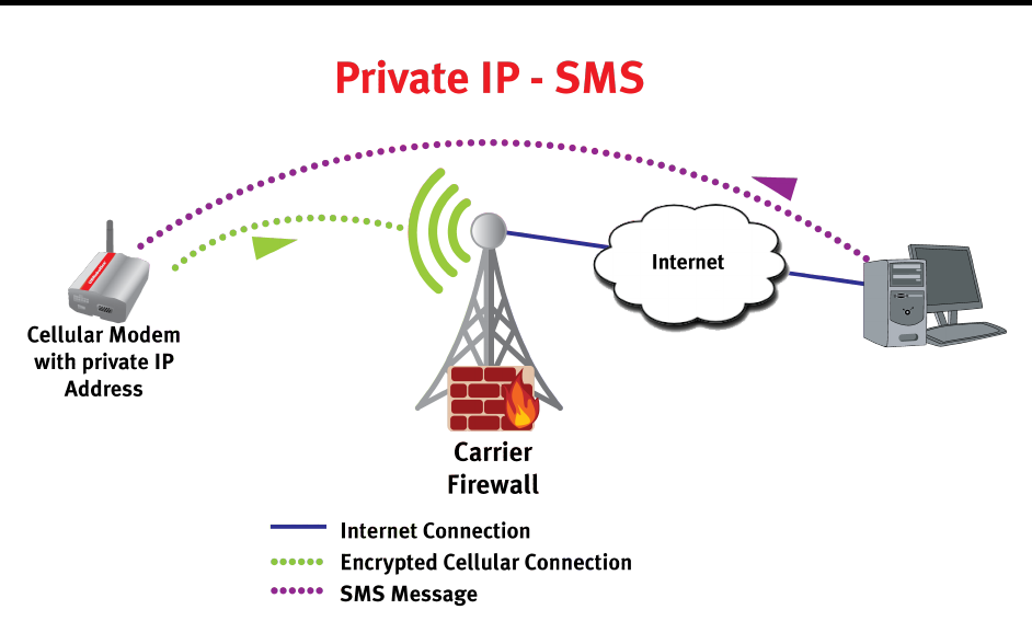
16
This system is very common. It allows the modem to be protected behind the carrier’s
firewall. Also, if your system doesn’t require the server to initiate communications with
the modem then this will work well. If you do require server initiated communications,
then you must support two communication paths, GPRS and SMS.
2.3 Public IP based
Network configuration used when both the device and the server have publicly
accessible IP addresses. In this configuration both the device and the server are aware
of each other’s IP address.

17
When both the device and the server use public IP addresses, then both TCP and UDP
messages can be transmitted in both directions between the remote server and the
device.
This scenario is simple but security must be built into the system to ensure that access
to the modem is restricted to only those you wish to communicate with your device.
Without such security, a malicious attack could result in sensitive material being lost, the
device being disabled, and/or a very high data bill.
2.4 Static vs Dynamic IP Addresses
In all three scenarios above the service can either include static or dynamic IP
addressing for the modems. Static IP addresses are great because you can simplify
your server application by building a static look-up table to keep track of which IP
address goes with which device.
The other option is dynamic IP addresses. In this case, each time your modem activates
a GPRS context, the modem may be given a different IP address. Also, the IP address
may be changed from time to time even when connected to the network. Courier M2M
software has the ability to help a server keep a dynamic look-up table of devices in a
dynamic IP environment.

18
2.5 Connection Methodology
There are two methodologies for a device to communicate with a server; push or pull.
Which methodology you employ will depend on your network configuration and your IP
address configuration. Courier M2M software supports both methodologies.
Using the serial port, you can configure Courier M2M before you ship the device to be
installed. This interface is ideal for writing a TCL, Python or Perl script. For example, if
you configure Courier M2M software for an asset tracking application, you would set
how often you wish the device to update the server with position information and you
would need to set the IP address of the server with which you wish to communicate.
Once the device is in the field, there are two ways the device can operate. First, the
device can be configured to always initiate the connection with the server, send data
and then close the socket. This is the push methodology. You can also design your
system so the device never initiates communications. Instead your server always
initiates the connection by opening the socket, sending data to the device and then
closing the socket once the transfer has completed. This is the pull methodology. Lastly,
you can design your system to work with both push and pull. In all cases, there is no
need to keep sockets open any longer than it takes to complete the data transfer
initiated by either the device or the server.
2.6 Data Connection
Enter AT+WOPEN=1 to start the Courier M2M application. A startup banner will display.
Lib Version 1.9.1
Courier M2M Wireless Device
Application Started
If the application is already started, the startup banner will not display and an OK
response will be given.
To use IP data services, you need to configure an APN. Your cellular account needs to
have data services, and the cellular provider must provide you with an APN string.
Enter AT$CGDCONT=1,”<cellular.apn.string>” to set the APN. Use AT+CGREG? to
verify GPRS registration.
AT+CGREG?
+CGREG: 0,1
OK
A response with 0,1 indicates that your device is registered on the GPRS network. A
response of 0,0 would indicate not registered. Once you are registered, Courier M2M
will automatically activate a PDP context. Enter AT$IP to verify the device’s IP address.
AT$IP
$IP: "<deviceID>",0,"203.0.113.1"
OK

19
3 NVM Queue
Because of the nature of wireless technologies, where the network connection may be
lost from time to time, Courier M2M software has a Non-Volatile Memory Queue where
all outgoing data packets are stored before transmission. This way, important data will
not be lost. If, for example, the connection is lost when sending a GPS based Geofence
violation message, the data will be sent immediately when the network connection is
regained.
Also, if you’ve set any watchdog timers or a periodic reboot timer, then the stored data
survives reboots as well.
4 Protocol Overview
4.1 Protocol
This document describes the different interfaces that can be used to setup and control
the device via AT Command formatted messages.
The ASCII protocol is designed to be simple and human readable and is available for
setting up the device either on-site via the device’s serial port (USB/RS232) or remotely
through raw sockets, telnet session, or SMS messages. The ASCII protocol is an AT
Command (Hayes modem) based command and response interface. The advantage of
the ASCII protocol is that it is human readable, simple to read and therefore, quick to
implement. The ASCII commands can be sent to the UARTS, USB or Telnet ports. The
commands may also be sent via SMS messages if that option is configured using the
AT$SMS command. The response to the AT command is sent back to the same port
from which the command was received.
4.2 ASCII Format
The ASCII protocol is designed to work across all communication bearers. It can be
used over SMS, TCP/UDP or a serial interface. The interface is based on the AT
command protocol (V.250 specification). Using this design principle, the same protocol
can be used for communication between the server and the device, communications
with a service technician over a serial interface and used at manufacturing time to test
the device.
The command’s intermediate and final responses are sent from the device in response
to the command. In the case of “events”, unsolicited responses are sent over the bearer
that initiated the command. Commands are described as “Read”, “Action” and “Test”.

20
The Read commands are used to query a setting on the device. Use an ASCII “?” as the
last character of the command to denote a Read command.
Action commands are used to assign values to settings on the device. The command
containing an ASCII “=” is used to denote a Parameter command. The “=” can be
followed by 0 or more parameters, depending on which parameters are required and
which are optional.
Action commands are used to initiate an action. When the command doesn’t include
parameters, the “=” or “?” after the command then it is an action command.
Test commands are used to verify the syntax of a particular command. The ASCII string
“=?” as the command’s last characters is used to show the syntax of a command.
Please refer to the V.250 specification for more background on the structure of the
ASCII protocol.

21
4.3 ASCII Command/Response Types
The following table defines the AT command based messages.
Type
Description
Events
AT$EVENTLABEL
Encode and decode Event Labels
AT$EVENTDISPLAY
Display events when they are generated
AT$EVENTFILTER
Configure a list of events to subscribe to for use in other event
capable commands
AT$EVENTSEQUENCE
Define a list of events to match to trigger a sequence event.
AT$EVENTGEN
Used to generate system or user defined events manually
Identification
AT$APPVERSION
Get the application and hardware version
AT$FWVERSION
Get the modem firmware version
AT$MODEMID
Return the modem ID, usually the IMEI
AT$SUBSCRIBERID
Return the subscriber ID, usually the IMSI
AT$DEVICEID
Set and Get the Device Id
AT$FEATURE
Gets the build features
Time
AT$TIME
Set and Get the current time
AT$AUTOTIME
Set and Get the Autotime Mode
AT$TIMERSTART
Start a timer
AT$TIMERSTOP
Stop a timer
AT$ALARMCLOCK
Configure or delete an alarm
Device Control
AT$SMSFORWARD
Set and Get SMS Forward Mode
AT$RESET
Reset the device
AT$REPORT
Configures which unsolicited reports are generated by the device
and report various device statuses
AT$LOWPOWERON
Enable low power mode
AT$LOWPOWEROFF
Disable low power mode
Communications
AT$CGDCONT
Set and Get PDP context
AT$IP
Returns the network IP address of the device
AT$PING
Allows a device to ping a remote server
Ethernet
AT$ENABLEETHERNET
Enable/Disable the Ethernet interface
AT$ETHERNETIP
Returns the Ethernet IP address of the device
AT$DHCPS
Set and Get DHCP settings for Ethernet Interface
AT$STATICIP
Set and Get static IP for Ethernet Interface

22
Type
Description
AT$DHCPDNS
Set and get DNS settings for the DHCP server
Endpoint / Bridge
AT$ENDPOINT
Set and Get Endpoint used for “Pass through” routing
AT$BRIDGECREATE
Query or Connect 2 endpoints completing a “Pass through” route
AT$BRIDGEDELETE
Define or query bridge DELETE parameters.
AT$ONLINE
Return serial endpoint to online data mode.
AT$EPWRITE
Write data to an Offline Data Mode Endpoint
AT$EPREAD
Read data from an Offline Data Mode Endpoint
Email
AT$ESERVER
Define and query Endpoint Server settings
AT$EMAILHDR
Define and query Email Header settings
Remote AT Commands
AT$TELNETPORT
Set and Get telnet port used for AT
AT$SMS
Set and Get SMS AT command configuration
FTP Commands
AT$FTPOPEN
Open an FTP session.
AT$FTPCLOSE
Close an FTP session.
AT$FTPMKDIR
Make a directory.
AT$FTPCWD
Change working directory.
AT$FTPDELDIR
Delete a directory.
AT$FTPDEL
Delete a file.
AT$FTPREN
Rename a file.
Tag File System
AT$TAGFORMAT
Format the Tag file system.
AT$TAGRECOMPACT
Recompact the FLASH containing the Tag file system.
AT$TAGINSTALL
Install a Tag file as either new cellular modem firmware or
software application.
AT$TAGDELETE
Delete a Tag.
AT$TAGCREATE
Create an empty tag file.
AT$TAGWRITE
Write data to a Tag.
AT$TAGCLOSE
Close a Tag file.
AT$TAGREAD
Read data from a Tag.
AT$TAGSYSINFO
Display system information on Tag file system.
AT$TAGLISTALL
List all Tag files in the file system.
AT$TAGDOWNLOADFTP
Download from FTP server to tag file.
AT$TAGDOWNLOADHTTP
Download from HTTP server to tag file.
AT$TAGUPLOADFTP
Upload from tag file to FTP server.
AT$TAGUPLOADHTTP
Upload from tag file to HTTP server.
GPIO
AT$GPIOCONFIG
Allocate, deallocate, save and delete from flash and view the

23
Type
Description
status and capabilities of GPIOs
AT$GPIOREAD
Read one or more GPIOs
AT$GPIOWRITE
Write to one or more GPIOs
AT$GPIOACTION
Allow multiple events to operate on one GPIO
AT$GPIOACTIONMULTI
Allow multiple GPIOs to be manipulated by one event.
GPS Tracking
AT$LOCATE
Set unsolicited locate time and get current location
AT$GEOFENCE
Set and get parameters for Geofence tracking
AT$SPEED
Set and get speed settings and status
AT$LOCATEEXT
Set and get extended location filter assignments
SENSOR
AT$SENSORCONFIG
Define a sensor driver.
AT$SENSORCALIBRATE
Define a calibration table for a sensor channel.
AT$SENSORTRIGGER
Define trigger events for reading a sensor channel.
AT$SENSORREAD
Read a sensor channel.
Config System
AT$CONFIG
Set and get configuration settings
System Variables
AT$VARIABLETHRESHOLD
Configure a variable threshold.
AT$VARIABLECOMPARE
Configure a variable comparison.
AT$VARIABLESET
Configure a variable to be modified.
AT$VARIABLESEND
Send a variable to an endpoint.

24
5 String Tokens
String tokens are placeholder variables that may be placed in any string that is passed
in to any software command. At runtime the string tokens are evaluated and replaced
with the appropriate values. This allows for creating dynamic strings that can be used
for file and directory names, or for SMS and email messages.
String tokens are inserted into a string with a percent sign (%) before and after the
name. For example, if a string contains the string token %year%, then it will be
replaced with "2013". The name is case sensitive. If a string token name is not
recognized, it is replaced with “%?%”. To include a percent sign in the string without
referring to a string token, insert “%%”.
The token name can be used with a prefix and/or postfix number to modify its meaning.
For example, if the string token “FILL” is inserted in a string as %10FILL46%, then it will
be replaced with 10 of the ASCII character 46 (period), or “……….”. If either number is
not included, it is assumed to be 0. Not all string tokens use the numbers.
String token processing can be enabled or disabled. When disabled, the original string
is not modified.
The table below lists all the string tokens. The current list can be queried with the
AT$STRINGTOKENS? Command.
Name
Description
Prefix #
Postfix #
system
%%
Insert a single percent sign
–
–
CR
Carriage return (default count=1)
count
–
CRLF
Carriage return, line feed (default count=1)
count
–
HT
Horizontal tab (default count=1)
count
–
LF
Line feed (default count=1)
count
–
FILL
Fill string with characters (default count=1)
count
character
lowpwr
Low power mode (0=disabled, 1=enabled)
–
–
time
year
Year (4 digits)
Min width
counter
month
Month
Min width
counter
monthname
Month name
–
counter
day
Day of the month
Min width
counter
dow
Day of the week (1=Sun, 7=Sat)
Min width
counter
downame
Day of the week name
–
counter
hourint
Hour in 24 hour format
Min width
counter
hourus
Hour in 12 hour format
Min width
counter
ampm
AM or PM
–
counter

25
Name
Description
Prefix #
Postfix #
minute
Minutes (2 digits)
–
counter
second
Seconds (2 digits)
–
counter
identification
mfg
Modem manufacturer
–
–
model
Modem model
–
–
subid
Subscriber Id
–
–
modemid
Modem id
–
–
deviceid
Device id
–
–
modulefirmver
Modem firmware version
–
–
appver
Software application version
–
–
platver
Software platform version
–
–
hwver
Modem hardware version
–
–
projname
Name of the project build.
–
–
features
Feature bitmap in hex.
–
–
counter
counter
General purpose counter. N=1-20
–
N
nvcounter
General purpose NVM counter. N=1-20
–
N
gpio
gpio
Status of GPIO pin
–
pin
endpoint
epbyteswritten
Bytes written to endpoint X buffer
–
X
eptransactions
Transactions written to endpoint X buffer
–
X
epbytesread
Bytes written to endpoint X buffer
–
X
ip
telnet
Telnet server status. 0=off, 1=on, 2=client connected
–
–
tcpserver
TCP server status. 0=off, 1=on, 2=client
connected
–
–
udpserver
UDP server status. 0=off, 1=on
–
–
ethernet
etheron
Ethernet on (0-1)
–
–
etherlink
Ethernet link status (cable connected)
–
–
gatewayip
Static IP address of the local ethernet interface
–
–
network
apn
Access Point Name for Context ID (1-4)
–
ID
sig
Signal strength
–
–
wanip
IP address from the cellular network
–
–
tag

26
Name
Description
Prefix #
Postfix #
tagmemtotal
Tag memory total bytes
–
–
tagmemdel
Tag memory deleted bytes
–
–
tagmemfree
Tag memory free bytes
–
–
tagrecompact
Tag recompact flag.
1=Recompact on next reset.
–
–
gps
longitudeF
GPS longitude, Float format
Min width
Decimal
places
latitudeF
GPS latitude, Float format
Min width
Decimal
places
speedF
GPS speed, Float format
Min width
Decimal
places
headingF
GPS heading, Float format
Min width
Decimal
places
altitudeF
GPS altitude, Float format
Min width
Decimal
places
accuracyF
GPS accuracy, Float format
Min width
Decimal
places
mileageF
GPS miles between updates, Float format
Min width
Decimal
places
latitude
Latitude (deg*1000000)
–
–
longitude
Longitude (deg*1000000)
–
–
heading
Heading (deg*10)
–
–
speed
Current speed (mph*10)
–
–
altitude
Altitude (feet*10)
–
–
numsat
Number of GPS satellites
–
–
accuracy
Accuracy (miles*1000000)
–
–
mileage
Miles between updates (*1000)
–
–
odometer
Accumulated miles *1000
–
–
fixtime
Fix time, secs since 1/1/1970
–
–
sensor
sensor
The current sensor stored value. Postfix # X = (Id*16)
+ channel.
X
5.1 STRINGSEND Events
These events are generated by the STRINGSEND commands. The EventType is 9.
The ObjectId for the event is the StringSend ID. See section 7 for more about events.
Name
EventId
Description
Started
1
A STRINGSEND transfer has started.
Done
2
A STRINGSEND transfer has completed.

27
Error
3
A STRINGSEND transfer encountered an error.
Aborted
4
A STRINGSEND transfer was aborted.
5.2 AT$STRINGTOKENS
This Command enables or disables the string token processing, and lists all string
tokens.
Action Command 5.2.1
The following shows the command (in bold) to enable or disable string token
processing.
AT$STRINGTOKENS=<mode>
$STRINGTOKENS: ”<deviceId>”,<status>
(OK | ERROR)
Read Command 5.2.2
The following shows the command (in bold) to list all string tokens with a brief
description.
AT$STRINGTOKENS?
$STRINGTOKENS: ”<deviceId>”,<status>,<mode>
$STRINGTOKENS: ”<deviceId>”,<status>,%name%,”Description”
…...(list of all string tokens)
(OK | ERROR)
!!!Parameters!
Parameter
Description
<deviceId>
The ID of the modem.
<status>
The status of the command.
<mode>
0 – Disable processing
1 – Enable processing
<status>
Description
0
Success
1050
Invalid <mode>.
5.3 AT$STRINGTEST

28
This Command is used to test the formatting of the dynamic string tokens. A string that
contains string tokens is entered and is processed. Its replacement string is displayed.
This provides an aid for developing dynamic strings to be used in other system
commands.
Action Command 5.3.1
The following shows the command (in bold) to test a string.
AT$STRINGTEST="<string with tokens>"
$STRINGTOKENS: ”<deviceId>”,<status>,”<replacement string>”
(OK | ERROR)
!!!Parameters!
Parameter
Description
<deviceId>
The ID of the modem.
<status>
The status of the command.
<status>
Description
0
Success
1050
Invalid string
Example 5.3.2
AT$STRINGTEST="Current date and time: %downame% %month%/%day%/%year%
%hourus%:%minute%:%second% %ampm%"
$STRINGTEST: "327004000672",0,"Current date and time: Wednesday 6/20/2012
5:38:36 PM"
OK
5.4 AT$STRINGSENDEMAIL
This Command is used to send an email with a string that may contain string tokens.
This command creates a temporary SMTP Email endpoint to send the email. The email
may be sent immediately, or triggered by any event.
The command parameters are saved to NVM and restored after power cycles, unless
there are no events specified. If the command is entered to be executed immediately,
then nothing is saved to NVM.
Action Command 5.4.1
The following shows the command (in bold) to send a string.

29
AT$STRINGSENDEMAIL=<strSendId>,<eServerId>,<emailHdrId>,"<msgString>"
[,<attachTagId>[,<compress>[,<eventLabel>[...,<eventLabel>]]]]
$STRINGSENDEMAIL: ”<deviceId>”,<status>
(OK | ERROR)
The above command response indicates the status of the command and its parameters.
If successful, then when triggered by an <eventLabel>, a connection will be established
with the SMTP email server, and the <msgString> will be sent. Unsolicited messages
will be output to indicate the progress:
$STRINGSENDEMAIL: ”<deviceId>”,<status>,< strSendId >,<transferStatus>
To delete a STRINGSENDEMAIL Id, enter the command with the StringSend Id as the
only parameter:
AT$STRINGSENDEMAIL=< strSendId >
Read Command 5.4.2
The following shows the command (in bold) to query the STRINGSENDEMAIL settings.
AT$STRINGSENDEMAIL?
$STRINGSENDEMAIL: ”<deviceId>”,<status>,<strSendId>,<eServerId>,<emailHdrId>,
"<msgString>",<attachTagId>,<compress>,<eventLabel>...,<eventLabel>
…...(list of all valid records)
(OK | ERROR)
!!!Parameters!
Parameter
Description
<deviceId>
The ID of the modem.
<status>
The status of the command.
<strSendId >
StringSendEmail identifier (1-20).
<eServerId>
Endpoint Server Id. The Eserver contains the SMTP
server’s IP address, and optional port, username, and
password.
emailHdrId
Email Header Id. The Email header contains the sender
and recipient information.
<msgString>
The body of the email, which may contain string tokens.
The tokens will be evaluated when the email transfer is
triggered to begin.

30
<tagId>
Not currently supported. Tag file to be attached to the
email.
<compress>
Not currently supported.
Type of compression performed on the tag file before
attaching to the email:
0 = None (default)
1 = zlib
2 = bzip
<eventLabel>
EventLabel in hex. This defines the event(s) that trigger
the sending of the email. There may be from 0 to 10
values. A null or 0 value specifies “immediate” (default).
Use the AT$EVENTLABEL command to aid with encoding
this parameter.
<transferStatus >
Status of the transfer process:
1 = Transfer has started.
2 = Email was sent successfully.
3 = An error was encountered.
4 = Transfer was aborted.
<status>
Description
0
Success
1050
Invalid StringSend Id
1052
Already in use
1055
Invalid Eserver Id
1056
Invalid EmailHdr Id
1100
Invalid Tag Id
Example 5.4.3
The following example sets up StringSendEmail Id 3 to send an email when timer 1
expires. The <eventLabel> for Timer 1 expiration is 00020103 (see section 10.5.1).
Event Type = 2 for Timers
Object Id = 1 for Timer 1
Event Id = 3 for Timer Expiration
The AT$EVENTLABEL command can be used to assist with encoding the correct hex
value:
AT$EVENTLABEL=2,1,3
$EVENTLABEL: "327004000672",0,"00020103"
OK
AT$ESERVER=1,"smtp.mail.example.com",587,"myemailid@example.com","mypasswd",2
AT$EMAILHDR=1,"myemailid@example.com","My Name","someone@example.com", ,,"My
Subject"

31
AT$STRINGSENDEMAIL=3,1,1,"Email body sent at %hourus%:%minute%:%second%
%ampm%",0,0,00020103
To test, this command creates Timer 1 with a duration of 30 seconds:
AT$TIMERSTART=1,300
Another alternative for triggering the email is to have it sent every time the modem
acquires a GPRS connection. For that, use the event for IP Address Changed (see
section 12.1):
Event Type = 50 for Network
Object Id = 0 (not used)
Event Id = 1 for IP Changed
AT$EVENTLABEL=50,0,1
$EVENTLABEL: "327004000672",0,"00320001"
AT$STRINGSENDEMAIL=3,1,1,"GPRS acquired at %hourus%:%minute%:%second%
%ampm%",0,0,00320001
5.5 AT$STRINGSENDSMS
This Command is used to send an SMS message with a string that may contain string
tokens. This command creates a temporary SMS endpoint to send the message. The
SMS may be sent immediately, or triggered by any event.
The command parameters are saved to NVM and restored after power cycles, unless
there are no events specified. If the command is entered to be executed immediately,
then nothing is saved to NVM.
Action Command 5.5.1
The following shows the command (in bold) to send a string.
AT$STRINGSENDSMS=<strSendId>,"<smsPhoneNum>","<msgString>"[,<eventL
abel> [...,<eventLabel>]]
$STRINGSENDSMS: ”<deviceId>”,<status>
(OK | ERROR)
The above command response indicates the status of the command and its parameters.
If successful, then when triggered by an <eventLabel>, the <msgString> will be sent.
Unsolicited messages will be output to indicate the progress:

32
$STRINGSENDSMS: ”<deviceId>”,<status>,<strSendId>,<transferStatus>
To delete a STRINGSENDSMS Id, enter the command with the StringSend Id as the
only parameter:
AT$STRINGSENDSMS=<strSendId>
Read Command 5.5.2
The following shows the command (in bold) to query the STRINGSENDSMS settings.
AT$STRINGSENDSMS?
$STRINGSENDSMS:
”<deviceId>”,<status>,<strSendId>,<smsPhoneNum>,"<msgString>",
<eventLabel>...,<eventLabel>
…...(list of all valid records)
(OK | ERROR)
!!!Parameters!
Parameter
Description
<deviceId>
The ID of the modem.
<status>
The status of the command.
<strSendId >
StringSendSms identifier (1-20).
<smsPhoneNum>
SMS Phone Number. This number must be a valid
destination phone number.
<msgString>
The content of the SMS message, which may contain
string tokens. The tokens will be evaluated when the
message is sent.
<eventLabel>
EventLabel in hex. This defines the event(s) that trigger
the sending of the SMS. There may be from 0 to 10
values. A null or 0 value specifies “immediate” (default).
Use the AT$EVENTLABEL command to aid with encoding
this parameter.
<transferStatus >
Status of the transfer process:
1 = Transfer has started.
2 = SMS was sent successfully.
3 = An error was encountered.
4 = Transfer was aborted.
<status>
Description
33
0
Success
1050
Invalid StringSend Id
1052
Already in use
Example 5.5.3
The following example sets up StringSendSms Id 2 to send an SMS when timer 1
expires. The <eventLabel> for Timer 1 expiration is 00020103 (see section 10.5.1).
Event Type = 2 for Timers
Object Id = 1 for Timer 1
Event Id = 3 for Timer Expiration
The AT$EVENTLABEL command can be used to assist with encoding the correct hex
value:
AT$EVENTLABEL=2,1,3
$EVENTLABEL: "327004000672",0,"00020103"
OK
AT$STRINGSENDSMS=2,”9195551234”,"SMS body sent at %hourint%:%minute%:
%second%",00020103
To test, this command creates Timer 1 with a duration of 30 seconds:
AT$TIMERSTART=1,300
5.6 AT$STRINGSEND
This Command is used to send a string that may contain string tokens to an existing
endpoint. The transfer may be triggered immediately, or by any event.
The command parameters are saved to NVM and restored after power cycles, unless
there are no events specified. If the command is entered to be executed immediately,
then nothing is saved to NVM.
Action Command 5.6.1
The following shows the command (in bold) to send a string.
AT$STRINGSEND=<strSendId>,<endpointId>,"<msgString>"[,<eventLabel>
[...,<eventLabel>]]
$STRINGSEND: ”<deviceId>”,<status>
(OK | ERROR)

34
The above command response indicates the status of the command and its parameters.
If successful, then when triggered by an <eventLabel>, the <msgString> will be sent to
the specified endpoint. Unsolicited messages will be output to indicate the progress:
$STRINGSEND: ”<deviceId>”,<status>,< strSendId >,<transferStatus>
To delete a STRINGSEND Id, enter the command with the StringSend Id as the only
parameter:
AT$STRINGSEND=< strSendId >
Read Command 5.6.2
The following shows the command (in bold) to query the STRINGSEND settings.
AT$STRINGSEND?
$STRINGSEND: ”<deviceId>”,<status>,<strSendId>,<endpointId>,"<msgString>",
<eventLabel>...,<eventLabel>
…...(list of all valid records)
(OK | ERROR)
!!!Parameters!
Parameter
Description
<deviceId>
The ID of the modem.
<status>
The status of the command.
<strSendId >
StringSend identifier (1-20).
<endpointId>
Endpoint Id. This endpoint must already exist.
<msgString>
The string to be sent, which may contain string tokens.
The tokens will be evaluated when the message is sent.
<eventLabel>
EventLabel in hex. This defines the event(s) that trigger
the sending of the string. There may be from 0 to 10
values. A null or 0 value specifies “immediate” (default).
Use the AT$EVENTLABEL command to aid with encoding
this parameter.
<transferStatus >
Status of the transfer process:
1 = Transfer has started.
2 = String was sent successfully.
3 = An error was encountered.
4 = Transfer was aborted.
<status>
Description

35
0
Success
1050
Invalid StringSend Id
1052
Already in use
1090
Invalid Endpoint Id
1091
Endpoint Id out of range
Example 1: Send Email 5.6.3
The following example sets up StringSend Id 4 to send the given string to endpoint 8
(which is an SMTP email endpoint) when timer 1 expires. The <eventLabel> for Timer 1
expiration is 00020103 (see section 10.5.1).
Event Type = 2 for Timers
Object Id = 1 for Timer 1
Event Id = 3 for Timer Expiration
The AT$EVENTLABEL command can be used to assist with encoding the correct hex
value:
AT$EVENTLABEL=2,1,3
$EVENTLABEL: "327004000672",0,"00020103"
OK
AT$ESERVER=1,"smtp.mail.example.com",587,"myemailid@example.com","mypasswd",2
AT$EMAILHDR=1,"myemailid@example.com","My Name","someone@example.com", ,,"My
Subject"
AT$ENDPOINT=8,8,1,1
AT$STRINGSEND=4,8,"String was sent at %hourint%:%minute%: %second%",00020103
To test, this command creates Timer 1 with a duration of 30 seconds:
AT$TIMERSTART=1,300
Example 2: Serial to TCP Endpoint Connection 5.6.4
This example shows how a string can be sent to a TCP server when the connection is
first made. A pass-through connection is established between a serial endpoint and a
TCP endpoint. Every time the TCP endpoint connects to the remote server, a string is
sent to the server.
The following commands set up StringSend Id 5 to send a string to TCP endpoint 6
when the TCP connection is opened to its remote server. This uses the TCP Open
event as the trigger to send the string. The <eventLabel> for endpoint 6 Open is
00650101 (see section 15.1.2).

36
Event Type = 101 for TCP endpoints
Object Id = 6 for endpoint 6
Event Id = 1 for TCP Open
The AT$EVENTLABEL command can be used to assist with encoding the correct hex
value:
AT$EVENTLABEL=101,1,1
$EVENTLABEL: "327004000672",0,"00650101"
OK
AT$STRINGSEND=5,6,"Connected %hourint%:%minute%:%second%%CRLF%Version
%appver%%CRLF%",00650101
Then the pass-through connection is set up between serial port 1 and the TCP server at
www.example.com, port 2025:
AT$ENDPOINT=6,1,2025,www.example.com
AT$BRIDGECREATE=1,1,6,2
AT$ENDPOINT=1,3,1
After a power cycle, or any other time the TCP connection is established, the TCP
server receives the string:
Connected 14:08:10
Version 1.00

37
6 System Variables
The System Variables subsystem manages two types of system variables:
1. Configuration – Configuration settings which are constant. These settings are
non-volatile and stored in NVM.
2. Status – Dynamic values that change during runtime. These values may or may
not be non-volatile.
System variables are signed 32-bit values, unless stated otherwise.
Events can be generated based on generic conditions such as when a variable
changes, or crosses a threshold value. This subsystem also provides the ability to do
generic work on any status variable at a regular interval.
6.1 Variable Identifiers
Every system variable has a unique identifier that is used manage that variable. The
identifier is a 24 bit value, with the most significant 16 bits specifying the parent
subsystem. The subsystem is the same as the Event Type field used by events (see
Table 7.1). The lower 8-bits specify the specific variable in the subsystem.
6.2 String Tokens
Each variable’s runtime value can be used in a string token. The name of the variable
doubles as its string token name. This permits the value to be used in any context that
accepts a string token.
In addition to each variable, the following string tokens are available:
Name
Description
Prefix #
Postfix #
varthreshold
Current state of the requested variable
threshold
–
thresholdId–
varcompare
Current state of the requested variable
comparison
–
compareId–
6.3 Events
The events below are generated by the system variables subsystem. They may be
used to trigger any action in the software that accepts events.
See Table 7.1 for the Event Type.
Name
EventType
ObjectId
EventId
Description
SENT
System
sendId
1
Variables were sent.

38
Variable
SEND ERROR
System
Variable
sendId
2
An error occurred during
send.
THRESHOLD_FALSE
System
Variable
thresholdId
3
Threshold became false.
THRESHOLD_TRUE
System
Variable
thresholdId
4
Threshold became true.
COMPARE_FALSE
System
Variable
compareId
5
Compare became false.
COMPARE_TRUE
System
Variable
compareId
6
Compare became true.
STATUS_CHANGED
variableId
128
Status variable was
modified.
CONFIG_CHANGED
variableId
129
Config variable was
modified.
6.4 List of Status Variables
The table below lists all the status variables in the system. The current list can be
queried with the AT$VARIABLESTATUS? Command.
Identifier
(hex)
Name
Description
nonVolatile
autoUpdt
endpoint
005A00+X
epbyteswrittenX
Bytes written to endpoint X
–
yes
005B00+X
eptransactionsX
Transactions written to
endpoint X
–
yes
005C00+X
epbytesreadX
Bytes read from endpoint X
–
yes
gpio
gpio
Status of GPIO pin
ip
003401
telnet
Telnet server status. 0=off,
1=on, 2=client connected
yes
003402
tcpserver
TCP server status. 0=off, 1=on,
2=client connected
yes
003403
udpserver
UDP server status. 0=off, 1=on
yes
ethernet
003501
etherlink
Ethernet link status (cable
connected)
yes
network
003201
sig
Signal strength
yes
counter
001000 +
N
counterN
General purpose counter. N=1-
20

39
Identifier
(hex)
Name
Description
nonVolatile
autoUpdt
001014 +
N
nvcounterN
Non-volatile counter. N=1-15
yes
tag
000C01
tagmemtotal
Tag memory total bytes
yes
000C02
tagmemdel
Tag memory deleted bytes
yes
000C03
tagmemfree
Tag memory free bytes
yes
000C04
tagrecompact
Tag recompact flag.
1=Recompact on next reset.
Yes
yes
gps
00C801
longitude
Longitude (deg*1000000)
yes
00C802
latitude
Latitude (deg*1000000)
yes
00C803
heading
Heading (deg*10)
yes
00C804
speed
Current speed (mph*10)
yes
00C805
altitude
Altitude (feet*10)
yes
00C806
numsat
Number of GPS satellites
yes
00C807
accuracy
Accuracy (miles*1000000)
yes
00C808
mileage
Miles between updates (*1000)
yes
00C809
odometer
Accumulated miles * 1000
yes
yes
00C80A
fixtime
Fix time, secs since 1/1/1970
(unsigned)
yes
sensor
0087MN
sensorX
The current sensor channel
reading for sensor M, channel
N. X=(M*16)+N
yes
6.5 AT$VARIABLESTATUS
This AT command displays a listing of all status variables in the system.
Read Command 6.5.1
The following shows the command (in bold) to query all status variables.
AT$VARIABLESTATUS?
$VARIABLESTATUS: ”<deviceId>”,<status>,<variableId>,”<variableName>”,
”<variableDesc>”,<nonVolatile>,<autoUpdt>,<avgNum>,<currentValue>
…...(list of all valid records)
(OK | ERROR)
!!!Parameters!
Parameter
Description

40
<deviceId>
The ID of the modem.
<status>
The status of the command.
0 = Success
<variableId>
Variable identifier
<variableName>
Short ASCII name for the variable.
<variableDesc>
Brief description of the variable.
<nonVolatile>
1 = Saved in NVM. 0 = Not saved in NVM
<autoUpdt>
1 = Updated automatically. 0 = Not updated automatically.
<avgNum>
Number of readings in rolling average.
0 – No averaging.
<currentValue>
The current value of the variable.
6.6 AT$VARIABLETHRESHOLD
This AT command configures variable thresholds. Every time the variable’s value
changes, it is compared with the configured threshold for the chosen condition. An
event is generated when the test changes between true and false. There can be more
than one threshold configured for a variable.
To prevent multiple events from being generated when a variable is teetering on the
threshold value, a margin can be configured. After a threshold becomes true and
generates the event, it will not generate a false event until the threshold becomes false
by more than the margin amount, and vice versa from false to true.
Set Command 6.6.1
The following shows the command (in bold) to configure a variable threshold.
AT$VARIABLETHRESHOLD=<thresholdId>,<variableId>,<thresholdValue>,
<compareType>[,<margin>]
$VARIABLETHRESHOLD: ”<deviceId>”,<status>
(OK | ERROR)
Delete Command 6.6.2
If <thresholdId> is the only parameter given, the threshold is deleted.
AT$VARIABLETHRESHOLD=<thresholdId>
$VARIABLETHRESHOLD: ”<deviceId>”,<status>
(OK | ERROR)
Read Command 6.6.3
The following shows the command (in bold) to query all variable thresholds.
AT$VARIABLETHRESHOLD?

41
$VARIABLETHRESHOLD: ”<deviceId>”,<status>,<thresholdId>,<variableId>,
<thresholdValue>,<compareType>,<margin>,<compareState>
…...(list of all valid records)
(OK | ERROR)
!!!Parameters!
Parameter
Description
<deviceId>
The ID of the modem.
<status>
The status of the command.
0 = Success
<thresholdId>
Threshold identifier
<variableId>
Variable identifier
<thresholdValue>
Threshold value to be compared with the variable
<compareType>
Type of comparison:
1 – Variable < Threshold
2 – Variable <= Threshold
3 – Variable = Threshold
4 – Variable >= Threshold
5 – Variable > Threshold
<margin>
Margin value. New events are not generated until the
comparison differs by this amount. This prevents multiple
events when a threshold is teetering between true and
false. Default = 0.
<compareState>
1 = The comparison is true. 0 = false
Example 6.6.4
The following example sets a threshold for the signal strength variable (0x3201) to be
greater than or equal to 20, with a margin of 3.
AT$VARIABLETHRESHOLD=1,3201,20,4,3
When the signal strength rises to 20 or more, the comparison will be true and the TRUE
event will be generated. The signal strength will have to fall to 17 or below in order to
change the comparison to false and generate the FALSE event.
6.7 AT$VARIABLECOMPARE
This AT command configures variable comparisons. The values of two variables are
compared for the chosen condition. An event is generated when the test changes
between true and false. There can be more than one comparison configured for a
variable. The comparison is reevaluated every time either variable changes.

42
To prevent multiple events from being generated when the variable values are making
the comparison teeter between true and false, a margin can be configured. After a
comparison becomes true and generates the event, it will not generate a false event
until the comparison becomes false by more than the margin amount, and vice versa
from false to true.
Set Command 6.7.1
The following shows the command (in bold) to configure a variable comparison.
AT$VARIABLECOMPARE=<compareId>,<variableId1>,<variableId2>,<compareTy
pe> [,<margin>]
$VARIABLECOMPARE: ”<deviceId>”,<status>
(OK | ERROR)
Delete Command 6.7.2
If <compareId> is the only parameter given, the comparison is deleted.
AT$VARIABLECOMPARE=<compareId>
$VARIABLECOMPARE: ”<deviceId>”,<status>
(OK | ERROR)
Read Command 6.7.3
The following shows the command (in bold) to query all variable comparisons.
AT$VARIABLECOMPARE?
$VARIABLECOMPARE:
”<deviceId>”,<status>,<compareId>,<variableId1>,<variableId2>,
<compareType>,<margin>,<compareState>
…...(list of all valid records)
(OK | ERROR)
!!!Parameters!
Parameter
Description
<deviceId>
The ID of the modem.
<status>
The status of the command.
0 = Success
<compareId>
Comparison identifier
<variableId1>
First variable identifier
<variableId2>
Second variable identifier
<compareType>
Type of comparison:
1 – Variable1 < Variable2
2 – Variable1 <= Variable2
3 – Variable1 = Variable2

43
4 – Variable1 >= Variable2
5 – Variable1 > Variable2
<margin>
Margin value. New events are not generated until the
comparison differs by this amount. This prevents multiple
events when a comparison is teetering between true and
false. Default = 0.
<compareState>
1 = The comparison is true. 0 = false
Example 6.7.4
The following example sets a comparison between counter1 and counter 2. The
comparison will be true if counter1 (0x1001) is less than counter 2 (0x1002), with a
margin of 5.
AT$VARIABLECOMPARE=1,1001,1002,1,5
When the counter1 is less than counter 2, the comparison will be true and the TRUE
event will be generated. Counter1 will have to be 5 or more greater than counter2 in
order to change the comparison to false and generate the FALSE event.
6.8 AT$VARIABLESET
This AT command changes the value of a variable whenever an event occurs. This can
also be used as a counter of events by setting the command to add one each time.
The command parameters are saved to NVM and restored after power cycles, unless
there are no events specified. If the command is entered to be executed immediately,
then nothing is saved to NVM.
Set Command 6.8.1
The following shows the command (in bold) to configure a variable update.
AT$VARIABLESET=<setId>,<variableId>,<operation>,<operand>[,<eventLabel>
[…,<eventLabel>]]
$VARIABLESET: ”<deviceId>”,<status>
(OK | ERROR)
Delete Command 6.8.2
If <setId> is the only parameter given, the update object is deleted.
AT$VARIABLESET=<setId>
$VARIABLESET: ”<deviceId>”,<status>
(OK | ERROR)

44
Read Command 6.8.3
The following shows the command (in bold) to query all update objects.
AT$VARIABLESET?
$VARIABLESET: ”<deviceId>”,<status>,<setId>,<variableId>,<operation>,<operand>,
<eventLabel>…,<eventLabel>
…...(list of all valid records)
(OK | ERROR)
!!!Parameters!
Parameter
Description
<deviceId>
The ID of the modem.
<status>
The status of the command.
0 = Success
<setId>
Set identifier
<variableId>
Variable identifier in hex.
<operation>
Operation to perform on the variable:
1 = Set to the <operand>
2 = Add <operand >
3 = Subtract <operand >
4 = Multiply by <operand >
5 = Divide by <operand >
6 = Mod by <operand>
7 = AND with <operand>
8 = OR with <operand>
9 = XOR with <operand>
10 = NOT (<operand> is ignored)
Values 11-20 are the same as above, except the
<operand> is interpreted as another variableId from which
the value is taken.
21 = Force evaluation of COMPAREs and THRESHOLDs,
and trigger an event. This is intended to be used during
startup.
22 = Load the current UNIX timestamp (<operand> is
ignored)
<operand>
The value of the operation may be either an actual value, or
another variableId that will supply the value, depending on
the operation:
If operation = 1-10 this is the value for the operation.
If operation = 11-20 this is variableId2 to supply the value.
<eventLabel>
EventLabel in hex. This defines the event(s) that trigger the

45
update. There may be from 0 to 10 values. A null or 0
value specifies “immediate” (default).
Use the AT$EVENTLABEL command to aid with encoding
this parameter.
Example 6.8.4
The following example shows how to keep a count of the number of system resets. The
counter nvcounter1 (0x1015) is saved in NVM so it survives power cycles. For each
system reset event, the count is incremented by 1.
The <eventLabel> for system reset is 00010002 (see section 7.3).
Event Type = 1 for System
Object Id = 0 (not used)
Event Id = 2 for Normal Start Up
The AT$EVENTLABEL command can be used to assist with encoding the correct hex
value:
AT$EVENTLABEL=1,0,2
$EVENTLABEL: "327004000672",0,"00010002"
OK
AT$VARIABLESET=1,1015,2,1,00010002
The counter can be manually reset to 0 with an “immediate” form of the command:
AT$VARIABLESET=1,1015,1,0
6.9 AT$VARIABLESEND
This AT command sends variables to an existing endpoint. The transfer may be
triggered immediately, or by any event.
The command parameters are saved to NVM and restored after power cycles, unless
there is no event specified. If the command is executed immediately, then nothing is
saved to NVM.
Set Command 6.9.1
The following shows the command (in bold) to configure a variable send object.
AT$VARIABLESEND=<sendId>,<endpointId>,<endFile>,<eventLabel>,<variableId
> […,<variableId>]

46
$VARIABLESEND: ”<deviceId>”,<status>
(OK | ERROR)
The above command response indicates the status of the command and its parameters.
If successful, then when triggered by the <eventLabel>, the <variableId> list will be sent
to the specified endpoint. An unsolicited message will be output to indicate the status:
$VARIABLESEND: ”<deviceId>”,<status>,<sendId>,<transferStatus>
Delete Command 6.9.2
If <sendId> is the only parameter given, the send object is deleted.
AT$VARIABLESEND=<sendId>
$VARIABLESEND: ”<deviceId>”,<status>
(OK | ERROR)
Read Command 6.9.3
The following shows the command (in bold) to query all variable send objects.
AT$VARIABLESEND?
$VARIABLESEND:
”<deviceId>”,<status>,<sendId>,<endpointId>,<endFile>,<eventLabel>,<variableId>
…,<variableId>
……(list of all valid records)
(OK | ERROR)
!!!Parameters!
Parameter
Description
<deviceId>
The ID of the modem.
<status>
The status of the command.
0 = Success
<sendId>
Variable Send identifier
<endpointId>
Destination Endpoint Id.
<endFile>
0 = Do not close file after the Send.
1 = Close the destination file after each Send (default).
<eventLabel>
EventLabel in hex. This defines the event that triggers the
transfer. A null or 0 value specifies “immediate” (default).
Use the AT$EVENTLABEL command to aid with encoding
this parameter.
<variableId>…
Variable identifier(s) in hex to be sent to the endpoint.
There may be from 1 to 10 variables in this list.
<transferStatus >
Status of the send:

47
1 = String was sent successfully.
2 = An error was encountered.
Example 6.9.4
The following example sets up VariableSend Id 1 to send two status variables via
endpoint 3 (which is a TCP client endpoint) when timer 2 expires. The two variables are
“counter5” with Id 1005 and “sig” with Id 3201.
The <eventLabel> for Timer 2 expiration is 00020203 (see section 10.5.1).
Event Type = 2 for Timers
Object Id = 2 for Timer 2
Event Id = 3 for Timer Expiration
The AT$EVENTLABEL command can be used to assist with encoding the correct hex
value:
AT$EVENTLABEL=2,2,3
$EVENTLABEL: “327004000672”,0,”00020203”
OK
AT$ENDPOINT=3,1,2025,www.example.com
AT$VARIABLESEND=1,3,1,20203,1005,3201
To test, this command creates Timer 2 with a duration of 30 seconds:
AT$TIMERSTART=2,300
7 Events
The Event subsystem is one of the two backbones of the software (along with Endpoints
and Bridges, described later). Every subsystem in The software is built on the event
backplane. This allows all subsystems to generate events and listen for events from any
other subsystem.
Every Event has 3 components:
Event
Listen
Generate
Event
Event Backplane
Timers
GPIO
Endpoint
GPS

48
• Event Type – This value describes which subsystem the event came from. For
example, was the event generated by a timer, GPIO, Endpoint, etc.
• Object ID – Each subsystem has a predefined number of available Object ID on
which Actions may be performed or which trigger events. In some cases, like
GPIOs, the system has already defined the GPIO numbers, which are also
interpreted as Object IDs. In some subsystems, for example Timers, the user is
allowed to define one or more objects that may generate an event or execute an
action (which may in turn, also generate events). This specifies which object ID
generated the event.
• Event ID – The identifier for the event that occurred within a subsystem. The
namespace for Event IDs are based on Event Type. In this document, Event IDs
for each subsystem are defined in each section.
Below are the definitions used when discussing events:
• Event – A notification to the system that a system state has changed or that an
action has occurred. Examples: Timer has expired or Device registered to the
Network.
• Action – A definition of system setting change or process to execute. Examples:
Write level high to GPIO23 or Start timer 1.
• Trigger – The act of generating an Event.
Example 1: (Action) Write level high to GPIO 23 when (Event) timer 1 expires, which
Triggers
Example 2: (Action) Start timer 1 when (Event) network registration occurs
7.1 Event Types
Each subsystem in the software has an Event Type number associated with it. This
value is used to interpret the context for the Object ID and Event ID.
Event Type Name
Event Type Number
System
1
Timer
2
Event System
3
GPIO
4
SIM
6
Voice Call
7
DTMF
8

49
String Token
9
Identity
10
Sequence
11
Tag
12
System Variable
15
Counter
16
SMS
17 (0x11)
Network
50
Network CSQ
51
Socket
52
Ethernet
53
TCP Client
54
FTP Server
55 (0x37)
Endpoint bytes written
90 (0x5A)
Endpoint transactions
91 (0x5B)
Endpoint bytes read
92 (0x5C)
Bridge
98 (0x62)
Endpoint General
100
Endpoint TCP
101
Endpoint UDP
102
Endpoint Serial
103
Endpoint SMS
104
Endpoint HTTP GET
105
Endpoint HTTP PUT
106
Endpoint HTTP POST
107
Endpoint EMAIL SMTP
108
Endpoint EMAIL POP
109
Endpoint FTP GET
110
Endpoint SSL TCP
111
Endpoint SSL HTTP GET
112
Endpoint SSL HTTP PUT
113
Endpoint SSL HTTP POST
114
Endpoint SSL FTP GET
115
Endpoint X-Modem
116
Endpoint Tag-Write
117
Endpoint SPI
118
Endpoint I2C
119
Endpoint FTP PUT
120
Endpoint SSL FTP PUT
121
Endpoint Tag Read
122
Endpoint Binary Parser
123
Endpoint AT Parser
124
Endpoint Filter
125

50
Endpoint Offline Data
126
Endpoint Binary Command Parser
127
Endpoint TCP Server Client Created
130
Endpoint TCP Server Client Deleted
131
Sensor Driver
135 (0x87)
GPS General
200
GPS Rectangular Geofence
201
GPS Circular Geofence
202
GPS Polygon Geofence
203
User Defined
3567
7.2 Event Labels
Even though there are three components to every event (Event Type, Object ID, and
Event ID), they can be combined to create an Event Label. An event label simplifies the
command line for linking events together. The Event Label is always interpreted as
hexadecimal. The event label structure is described below:
Event Type
Object ID
Event ID
31
...
16
15
...
8
7
...
0
Event Label bits Figure 1.
If the Event Type, Object ID and/or Event ID is 0 then this means wildcard that means
“All”. An example of how to use this wildcard is, assume you wish to generate an event
label that will be used to listen for any GPIO event. In this case you would make the
Event Type equal to GPIO and the object ID and Event ID would be 0.
7.3 System Events
System Events apply to the whole system and are not tied to a specific subsystem.
System Event Type: 1
System Event
ID
System Event
Name
Description
1
Power On
The software has started.
2
Normal Start Up
All of the software subsystems have
initialized.
3
Start Up from Error
CPU exception, such as null pointer or

51
divide by 0.
4
Install Successful
A firmware tag file was installed and
activated.
5
Install Failed
A firmware tag file failed to install.
7.4 Event Label Command
This AT command is a utility command used to encode Event Labels in order to
configure the software subsystem to receive events or to decode Event Labels. This
command is not really intended for use during normal operation since it doesn’t control
any part of Courier M2M.
AT$EVENTLABEL 7.4.1
The $EVENTLABEL command is provided to allow for easy calculation of event labels
for use as action triggers. An event label represents three pieces of information: an
Event Type, and Object Identifier, and an Event ID.
The AT command is contextual. If you enter only one parameter it is assumed that the
parameter is an Event Label that needs to be decoded. The Event Label is always
interpreted as hexadecimal. If three parameters are entered then it is assumed that an
Event Label needs to be encoded based on the Event Type, Object ID and Event ID.
These parameters are always interpreted as decimal values.
Command:
AT$EVENTLABEL=<eventType>,<objectId>,<event>
Response:
$EVENTLABEL:“<deviceId>”,<status>,<eventLabel>
OK
Command:
AT$EVENTLABEL=<eventLabel>
Response:
$EVENTLABEL:
“<deviceId>”,<status>,<eventType>,<objectId>,<eventId>
OK
Please refer to section 2.3.1 for the definitions of the Event Types and 2.3.2 for the
definition of the Event Label.
A sample use for the $EVENTLABEL command is shown below. In this command, a
timer is created, and the $EVENTLABEL command us used to calculate a label for use
as a trigger in a GPIO command.
Ex 1: Sample $EVENTLABEL Usage

52
AT$TIMER=4,5,1
Create periodic timer with timer ID 4 and a
500ms duration to start immediately
OK
Success response from $timer command
AT$EVENTLABEL=2,4,3
Calculate an event label for a timer Event
Type 2 (timer object), object ID 4 (timer ID
4), and event ID 3 (timer expiration)
$EVENTLABEL:
"327004006981",0,"00402003"
OK
$eventlabel response with the muxed event
label 00402003
AT$GPIO=5,4,00402003,23,24
Create a GPIO action with an ID of 5, action
of 4 (toggle level), an event Id of 00402003,
to act on GPIOS 23 and 24
OK
Success creating action from $GPIO
command
!
7.5 Event Display Command
The $EVENTDISPLAY command turns on unsolicited responses for desired event
classes. Granularity and filtering is defined by the provided parameters. If only an
Event Type is provided, all events for the provided Event Type will be returned. If an
object Id is also provided, the results will be filtered by Event Type and object Id. If all
three parameters are provided, only events matching all three parameters will be
returned. A value of zero is used to denote all events. Only one event display setting
can be active at a time.
This command is for debugging purposes.
AT$EVENTDISPLAY 7.5.1
Action'command'
Enable or disable display of event.
AT$EVENTDISPLAY=<on/off>,<eventType>,<objectId>,<eventId>
$EVENTDISPLAY: ”<deviceId>”,<status>
(OK | ERROR)

53
Read'command'
AT$EVENTDISPLAY?
$EVENTDISPLAY: ”<deviceId>”,<status>,<eventLabel>
(OK | ERROR)
Unsolicited'response'
$EVT: “<deviceId>”,<status>,<eventType>,<objectId>,<eventId>
Parameter
Description
<on/off>
0 = Unsolicited event indications are disabled (default)
1 = Unsolicited event indications are enabled
<eventType>
See table in chapter 7.1
<objectId>
Specific object ID within the referenced EventType
<eventId>
Specific event ID within the referenced EventType
<eventLabel>
The current registered event label, in hex.
Examples:
AT$EVENTDISPLAY=1,0,0,0 //Display all events – NOT ALLOWED!
$EVENTDISPLAY: "327004096909",1013
OK
AT$EVENTDISPLAY=1,2,0,0 //Display all Timer events
$EVENTDISPLAY: "327004096909",0
OK
AT$EVENTDISPLAY=1,2,1,0 //Display all events for Timer 1
$EVENTDISPLAY: "327004096909",0
OK
AT$EVENTDISPLAY=1,2,1,3 //Display all timer expiring events
$EVENTDISPLAY: "327004096909",0 //for Timer 1
OK
7.6 Event Filters
Event filters create lists of desired event labels to be passed to and used by other
commands. Their primary function is for use in event sequences, but they can also be
used in place of a list of events for some commands.
7.7 Events
The events below are generated by an EventFilter. They may be used to trigger any
action in the software that accepts events.

54
The Event Type is 3 for Events. The Event ObjectId is the EventFilter Id value.
Name
EventId
Description
EVENTFILTER_TRIGGERED
1
The EventFilter was triggered. This is
effectively an OR of all event labels in the
EventFilter.
AT$EVENTFILTER 7.7.1
The event filter command is used to create an event filter Id with associated events for
use by the $EVENTSEQUENCE command. Only events matching the event filter will
be passed to the event sequence. Zeros can be used as wildcards to match multiple
objects or event IDs for more or less granularity as needed.
Action Command
Delete an event filter
AT$EVENTFILTER=<objectId>
OK
Create and configure an event filter
AT$EVENTFILTER=<objectId>,<eventLabel>[,...<eventLabelN]
$EVENTFILTER: “<moduleId>”,<status>,<objectId>,”eventLabel>”{,...”<eventLabelN>”]
OK
objectId
ID for use when referencing the configured event filter in later
commands
eventLabel
Label of event or events that are listened for by this filter
Read'Command'
AT$EVENTFILTER?
$EVENTFILTER: “<moduleId>”,<status>,<objectId>,”eventLabel>”{,...”<eventLabelN>”]
[$EVENTFILTER:“<moduleId>”,<status>,<objectId>,”eventLabel>”{,...”<eventLabelN>”]]
OK
Example'
This example will create a filter with filter id 1 to include all DTMF tone events.
AT$EVENTFILTER=1,00080000
$EVENTFILTER: "327004006981",0,1,"00080000"

55
OK
Event filter 1 can now be used in an event sequence command. The event sequence
will monitor all DTMF tone events, but only trigger on the specific event defined in the
event sequence command.
7.8 Event Sequences
These commands allow users to create custom events based on two or more other
events. Event filter commands will restrict the list of received commands to those
specified in the corresponding event filter command. Event sequence commands can
be paired with configured event filters to create custom events. Event sequences, for
example, could be used to match a sequence of DTMF tones.
7.9 Events
The events below are generated by an EventSequence. They may be used to trigger
any action in the software that accepts events.
The Event Type is 11 (0x0B) for EventSequence. The Event ObjectId is the
SequenceId value.
Name
EventId
Description
SEQUENCE_MATCH
1
Complete sequence matched.
EVENT_MATCH
2
One event in the sequence matched (strict only).
SEQUENCE_FAIL
3
Sequence failed (strict only).
AT$EVENTSEQUENCE 7.9.1
The EventSequence command defines a sequence of events that must be matched to
trigger an EventSequence event. Events in a sequence can be configured to be loosely
interpreted (i.e. out of order, or with other events in between) or strictly interpreted (in
order, no interruptions) depending on the desired application. The $EVENTSEQUENCE
command is used in combination with the $EVENTFILTER command. The EventFilter
defines which events to listen for, then the sequence defines the subset which will
trigger the Sequence event.
For example, if a user wanted to trigger an event based on DTMF tones, an event filter
would be created that would listen to all DTMF tones. Then, a strict
$EVENTSEQUENCE could be created with the desired tone order.

56
Action'Command'
Delete an event sequence:
AT$EVENTSEQUENCE=<objectId>
OK
Create and configure an event sequence:
AT$EVENTSEQUENCE=<objectId>,<filterId>,<mode>,<eventLabel1>,<eventLabel2>
[,...<eventLabelN>]
$EVENTSEQUENCE:
“<deviceId>”,<status>,<objectId>,<filterId>,<mode>,”<eventLabel1>”, ”<eventLabel2>”[,...”<e
ventLabelN>”]
OK
!!!Parameters!
Parameter
Description
<deviceId>
The ID of the modem.
<status>
The status of the command.
0 = Success
1050 = Bad parameter or too many eventLabels
1065 = Invalid object
objectId
ID for use when referencing the configured event sequence
in later commands
filterId
ID for an event filter created in earlier $EVENTFILTER
commands. This restricts the events to consider in the
sequence.
mode
Match mode:
0 – AND, non-strict. Match all the listed events in any
sequence.
1 – AND, strict. Match all the listed events exactly in the
defined sequence.
2 – OR. Match any one event in the defined sequence.
eventLabel1
First event in the sequence. Enter all eventLabels in hex.
eventLabel2
Second event in the sequence.
eventLableN
Nth event in the sequence. There may be up to 16 values.
Read'Command'
AT$EVENTSEQUENCE?
$EVENTSEQUENCE:
“<moduleId>”,<status>,<objectId>,<filterId>,<mode>,”<eventtLabel1>”, ”<eventLabel2>”[,...”
<eventLabelN>”]
…[more records]…
OK

57
Example'
This example uses the event filter id=1 created in the Event filter section (7), which
filters all DTMF tone events. To further fine tune event triggers, the event sequence
defines the exact events on which to trigger. This sequence will trigger if a DTMF tone 1
and DTMF tone 2 are detected, in that order.
AT$EVENTSEQUENCE=1,1,1,00080001,00080002
$EVENTSEQUENCE: "327004006981",0,1,1,1,"00080001","00080002"
OK
When DTMF tone 1 and 2 are detected, an event will be generated. This event can be
used as a trigger for a command to be executed. For example, GPIO20 can be
configured to go High if the sequence above happens.
AT$GPIOACTION=2,1,20,000B0101
GPIOACTION: "327004006981",0,2,1,20,"000B0101"
OK
To summarize, this configuration will cause GPIO 20 to go High when DTMF tone 1
followed by tone 2 is detected.
7.10 AT$EVENTGEN
The $EVENTGEN command allows users to trigger events manually. Triggered events
can be either defined system events or custom user defined events. This is especially
useful for testing the behavior of a sequence of event driven commands.
Parameter command
$EVENTGEN will accept either an event label or the corresponding separate event
values. Both forms of the command are shown below. Values should be in hexadecimal
format.
AT$EVENTGEN=<eventLabel>
$EVENTGEN: “<moduleId>”,<statusId>,<eventType>,<objectId>,<eventId>
OK
Or
AT$EVENTGEN=<eventType>,<objectId>,<eventId>
$EVENTGEN: “<moduleId>”,<statusId>,<eventType>,<objectId>,<eventId>
OK

58
8 Power Management
These commands allow the modem to be put into low power mode. In the low power
state, the modem is fully powered but the internal processor is in sleep state for a low
power consumption mode. The software is suspended, waiting for a timer expiration,
SMS message, or data connection to wake it up. To achieve the minimum power
consumption during low power mode, the following conditions must be met:
• Serial port must not be connected
• No pending AT command output can be queued
• USB port must not be connected
• Ethernet interface must be disabled (AT$ENABLEETHERNET=0)
The following commands are supported:
• AT$LOWPOWERON – Configures and queries events and time duration for
enabling low power mode.
• AT$LOWPOWEROFF – Configures and queries events for disabling low power
mode.
The Low Power Mode parameters are saved to NVM and restored after power cycles,
unless there are no events specified. If the command is entered to be executed
immediately, then nothing is saved to NVM.
8.1 Events
These system events are generated by the low power mode. The EventType is 1. The
ObjectId for the event is not used. See section 7 for more about events.
Name
EventId
Description
LOW POWER ENABLED
6
Low power mode was enabled.
LOW POWER
DISABLED
7
Low power mode was disabled.
8.2 String Tokens
This subsystem defines the follow dynamic string tokens:
Name
Description
Prefix #
Postfix #
lowpwr
Low power mode (0=disabled, 1=enabled)
–
–

59
8.3 AT$LOWPOWERON
This command configures or queries the events and time duration for low power mode.
Low power mode can be enabled immediately, or triggered to be enabled later by one or
more events. When low power mode is enabled, it generates a LOW POWER
ENABLED event. When the time duration expires, low power mode is disabled and it
generates a LOW POWER DISABLED event.
Action Command 8.3.1
The following shows the command (in bold) to enable low power mode.
AT$LOWPOWERON=<duration>[,<eventLabel>[…,<eventLabel>]]
$LOWPOWERON: ”<deviceId>”,<status>
(OK | ERROR)
Delete Configuration 8.3.2
If <duration> is the only parameter given and is equal to 0, all LOWPOWERON events
and the time duration will be deleted.
AT$LOWPOWERON=<0>
$LOWPOWERON: ”<deviceId>”,<status>
(OK | ERROR)
Read Command 8.3.3
The following shows the command (in bold) to query the parameters for enabling low
power mode.
AT$LOWPOWERON?
$LOWPOWERON: ”<deviceId>”,<status>,<duration>,<isEnabled>[,<eventLabel>[…,
<eventLabel>]]
(OK | ERROR)
!!!Parameters!
Parameter
Description
<deviceId>
The ID of the modem.
<status>
The status of the command.
0 = Success
<duration>
The length of time low power mode is enabled (in 100ms
increments).
<isEnabled>
0 = Low power mode is disabled.
1 = Low power mode is enabled.
<eventLabel>
EventLabel. This defines the event(s) that trigger the

60
enabling of a low power mode. There may be from 0 to 10
values. A null or 0 value specifies “immediate” (default).
Use the AT$EVENTLABEL command to aid with encoding
this parameter.
Example 8.3.4
The following example shows how to configure low power mode to be enabled upon
receiving a GPIO event. When triggered, low power mode will stay enabled for 5
minutes (300 seconds), then it will be disabled automatically.
The <eventLabel> for GPIO pin 29 going high is 00041D02 (see section 25.1).
Event Type = 4 for GPIO
Object Id = 29 for pin 29
Event Id = 2 for input high
The AT$EVENTLABEL command can be used to assist with encoding the correct hex
value:
AT$EVENTLABEL=4,29,2
$EVENTLABEL: "327004000672",0,"00041d02"
OK
AT$LOWPOWERON=3000,00041D02
8.4 AT$LOWPOWEROFF
This command configures or queries the events for disabling low power mode. Low
power mode can be disabled immediately, or triggered later by one or more events.
When low power mode is disabled, it generates a LOW POWER DISABLED event.
Action Command 8.4.1
The following shows the command (in bold) to disable low power mode.
AT$LOWPOWEROFF=<eventLabel>[…,<eventLabel>]
$LOWPOWEROFF: ”<deviceId>”,<status>
(OK | ERROR)
Delete Configuration 8.4.2
If a single <eventLabel> is the only parameter given and is equal to 0, all
LOWPOWEROFF events will be deleted.

61
AT$LOWPOWEROFF=0
$LOWPOWEROFF: ”<deviceId>”,<status>
(OK | ERROR)
Immediate Disable 8.4.3
To disable low power mode immediately, enter the command with 2 <eventLabel>
parameters = 0:
AT$LOWPOWEROFF=0,0
$LOWPOWEROFF: ”<deviceId>”,<status>
(OK | ERROR)
Read Command 8.4.4
The following shows the command (in bold) to query the parameters for disabling low
power mode.
AT$LOWPOWEROFF?
$LOWPOWEROFF: ”<deviceId>”,<status>,<isEnabled>[,<eventLabel>[…,
<eventLabel>]]
(OK | ERROR)
!!!Parameters!
Parameter
Description
<deviceId>
The ID of the modem.
<status>
The status of the command.
0 = Success
<isEnabled>
0 = Low power mode is disabled.
1 = Low power mode is enabled.
<eventLabel>
EventLabel. This defines the event(s) that trigger the
disabling of a low power mode. There may be from 0 to 10
values. A null or 0 value specifies “immediate” (default).
Use the AT$EVENTLABEL command to aid with encoding
this parameter.
Example 8.4.5
The following example shows how to configure low power mode to be disabled when
GPIO pin 28 goes high.
The <eventLabel> for GPIO pin 28 going high is 00041C02 (see section 25.1).

62
Event Type = 4 for GPIO
Object Id = 28 for pin 28
Event Id = 2 for input high
The AT$EVENTLABEL command can be used to assist with encoding the correct hex
value:
AT$EVENTLABEL=4,28,2
$EVENTLABEL: "327004000672",0,"00041c02"
OK
AT$LOWPOWEROFF=00041C02

63
9 Identification Commands
This set of commands may be used to query information that identifies the device and
the device’s capabilities. All of these commands are read only. There are a number of
different components and the version information is distinct for each component. Here is
an overview of the different components that have their own version numbers.
Application Version
The version of the hardware and application
that represents the wireless embedded
device.
Modem Version
The version of firmware loaded on the
cellular modem.
9.1 Events
The Identification subsystem generates events.
Identification Event Type: 10
Event ID
Event Name
Description
1
Device ID Change
This Event is triggered when the Device ID is
modified with AT$DEVICEID.
9.2 String Tokens
This subsystem defines the following dynamic string tokens:
Name
Description
Prefix #
Postfix #
subid
Subscriber Id
–
–
modemid
Modem id
–
–
deviceid
Device id
–
–
modulefirmve
r
Modem firmware version
–
–
appver
Software application version
–
–
platver
Software platform version
–
–
hwver
Modem hardware version
–
–

64
9.3 Get Application Version Command
This command set is used to get the application, firmware, and hardware versions of the
application.
The following command is supported:
• AT$APPVERSION– Read command
AT$APPVERSION 9.3.1
AT command used to get the version of the Courier M2M Application software, library
software, and hardware. The version can only be read.
Read'Command'
The following shows the command to read the versions, followed by the expected
output.
Command:
AT$APPVERSION
Response:
$APPVERSION:
“<deviceId>”,<status>,”<applicationVersion>”,”<firmwareVersion>”,
”<build_time>”,”<hardwareVersion>”
OK
Parameters'9.3.1.1.1.1
9.4 Get Firmware Version Command
This command set describes the Commands available to get the cellular modem
firmware version of the device.
The following command is supported:
• AT$FWVERSION– Read command
Parameter
Description
<deviceId>
The ID of the modem.
<status>
0 – Success
<applicationVersion
>
Version string set by the application.
<firmwareVersion>
<majorNumber>.<minorNumber>.<buildNumber>
<build_time>
Date and time when software was created
<hardwareVersion>
<majorNumber>.<minorNumber>

65
AT$FWVERSION 9.4.1
AT command used to get the version of the modem firmware. The version can only be
read.
Read!Command!9.4.1.1.1
The following shows the command to read the version, followed by the expected output.
Command:
AT$FWVERSION
Response:
$FWVERSION: “<deviceId>”,<status>,”<firmwareVersion>”
OK
Parameters'
9.5 Get Modem ID Command
This command set is available to get the ID of the cellular modem, usually the device
IMEI.
The following command is supported:
• AT$MODEMID– Read command
AT$MODEMID 9.5.1
AT command used to get the modem ID. The modem ID can only be read.
Read'Command'
The following shows the command to read the version, followed by the expected output.
Command:
AT$MODEMID
Response:
$MODEMID: “<deviceId>”,<status>,”<modemId>”
OK
''''Parameters'
Parameter
Description
<deviceId>
The ID of the modem.
<status>
0 – Success
Parameter
Description
<deviceId>
The ID of the modem.
<status>
0 – Success
<firmwareVersion>
The firmware version as returned by the modem

66
<modemId>
Modem ID
9.6 Get Subscriber ID Command
This command set is available to get the Subscriber ID attached to this device. For GSM
devices this value will be the IMSI. The subscriber ID should not be confused with the
modem ID. For GSM devices, if the SIM card isn’t inserted then no Subscriber ID will be
available.
The following command is supported:
• AT$SUBSCRIBERID– Read command
AT$SUBSCRIBERID 9.6.1
AT command used to get the subscriber ID. The subscriber ID can only be read.
Read'Command'
The following shows the command to read the version, followed by the expected output.
Command:
AT$SUBSCRIBERID
Response:
$SUBSCRIBERID: “<deviceId>”,<status>,”<subscriberId>”
OK
''''Parameters'
Parameter
Description
<deviceId>
The ID of the modem.
<status>
0 – Success
<subscriberId>
Subscriber ID
9.7 Device Identification
This command set is available to query and modify the ID of the device. It is important
that you provision each device you send in the field to have a unique device ID.
By default, the device ID is the 12 digits of the IMEI that uniquely identify the modem.
You can select to automatically generate the device ID based off the modem ID (IMEI),
the subscriber ID (IMSI), or disable auto-generated and instead specify your own ID.
The following command is supported:
• AT$DEVICEID – Action and Read commands
Refer to the following table for auto-generation types:

67
Auto-gen Type
Description
0
Generate device ID from modem ID (IMEI)
1
Generate device ID from subscriber ID (IMSI)
2
Disable autogen and specify a custom ID
AT$DEVICEID 9.7.1
AT command used to get and set the ID of the device, along with how the device ID is
auto-generated. The device ID can be set or read.
Action'Command/Response'
The following shows the command (in bold) to set the device ID, followed by the
expected output. If Autogen_Type = 2, then the “DeviceId” must be specified.
Command:
AT$DEVICEID=<Autogen_Type>[, “device Id”]
Response:
$DEVICEID: “<deviceId>”,<status>,<Autogen_Type>
OK|ERROR
Read'Command/Response'
The following shows the command (in bold) to read the device ID, followed by the
expected output.
Command:
AT$DEVICEID?
Response:
$DEVICEID: “<deviceId>”,<status>,<Autogen_Type>
OK|ERROR
!!!Parameters!
Parameter
Description
<deviceId>
The ID of the modem.
<status>
The status of the command.
0 = OK
1012 = NV save error
1050 = Invalid parameter value
<Autogen_Type>
0 – Generate device ID from modem ID (IMEI)
1 – Generate device ID from subscriber ID (IMSI)
2 – Disable autogen and specify a custom ID
9.8 Get Build Features
This command set is available to get the application firmware build features.

68
The following command is supported:
• AT$FEATURE – Read command
AT$FEATURE 9.8.1
AT command used to get the build features of the application software. The build
features can only be read.
Read'Command'
The following shows the command (in bold) to read the build features, followed by the
expected output.
Command:
AT$FEATURE?
Response:
$FEATURE: “<deviceId>”,<status>,”<projName>”,<featureBitmap>
OK
''''Parameters'
Parameter
Description
<deviceId>
The ID of the modem.
<status>
0 = Success
<projName>
Name of the build project
<featureBitmap>
A hex value of bits representing current features.
If bit is set, the feature is enabled.
Bit 0: Trial build
Bit 1: Debug build.
Bit 2: Model restricted
Bit 3: IMEI restricted
Bit 4: Ethernet interface
Bit 5: GPS tracking

69
10 Time
This section defines the commands used to control the device clock, timers and events
generated based on time.
10.1 Events
The Timer subsystem generates events.
Timer Event Type: 2
Event ID
Event Name
Description
1
Timer Start
This Event is triggered when a timer is started or
restarted.
2
Timer Stop
This Event is triggered when a timer is stopped
before it has a chance to expire.
3
Timer Expired
This Event is triggered when a timer expires.
4
Clock Changed
This Event is triggered when the system clock is
changed.
5
Clock Alarm
This Event is triggered when the Clock has
reached the time of an Alarm.
10.2 String Tokens
This subsystem defines the following dynamic string tokens:
Name
Description
Prefix #
Postfix #
year
Year (4 digits)
Min width
counter
month
Month
Min width
counter
monthname
Month name
–
counter
Day
Day of the month
Min width
counter
dow
Day of the week (1=Sun, 7=Sat)
Min width
counter
downame
Day of the week name
–
counter
hourint
Hour in 24 hour format
Min width
counter
hourus
Hour in 12 hour format
Min width
counter
ampm
AM or PM
–
counter
minute
Minutes (2 digits)
–
counter
second
Seconds (2 digits)
–
counter
Some of the tokens that return a numeric parameter accept a prefix, which specifies the
minimum width. If the number requires fewer characters than the minimum width, it will
be padded with zeros.

70
Using a Stored Timestamp 10.2.1
If the optional postfix is given, a UNIX timestamp stored in a counter is used instead of
the current system time. The postfix is formed from the lower 8 bits of the variable ID;
the volatile counters are accessed with postfixes 1-20, and the non-volatile counters
continue at 21.
When using this feature, operation 22 of the VARIABLESET command may be useful.
This can be used to store the current UNIX timestamp in a system variable, either
immediately or in response to an event.
Example'
The following example configures a timer that expires once every minute. The timer’s
expire event is used to store the current timestamp in counter1, and the counter’s
STATUS_CHANGED event is used to send a formatted time string to an endpoint.
Generate the event label for the timer1 expire event:
at$eventlabel=2,1,3
$EVENTLABEL: "327004106556",0,"00020103"
OK
Configure timer1 to restart automatically after it expires:
at$timerstart=1,600,20103
$TIMERSTART: "327004106556",0
OK
The timer must be manually started the first time:
at$timerstart=1,0
$TIMERSTART: "327004106556",0
OK
Now that the timer is configured, use $VARIABLESET operation 22 to listen for the
timer1 expire event and store the current timestamp in counter1:
at$variableset=1,1001,22,0,20103
$VARIABLESET: "327004106556",0
OK
Wait for the value in counter1 to be updated using the STATUS_CHANGED event, then
send a string containing the time to endpoint1:
at$stringsend=1,1,"Timer expire: %monthname1% %day1% %year1%
%hourus1%:%minute1%:%second1% %ampm1%%CRLF%",100180
$STRINGSEND: "327004106556",0
OK

71
The formatted time string will now be sent to the endpoint whenever the timer expires.
To watch this in real time, you can open up endpoint1 on your device’s serial port (use
“+++” to exit).
at$endpoint=1,3,1
$ENDPOINT: "327004106556",0
OK
10.3 Manually Set and Get Device Clock
This command set is available to get the clock on the device or manually configure the
time and date on the device. The following command is supported:
• AT$TIME – Action and Read commands
AT$TIME 10.3.1
AT command used to get and set the current time and date on the device.
Action'Command/Response'
The following shows the command (in bold) to set the date and time, followed by the
expected output.
Command:
AT$TIME=”<time>”
Response:
$TIME: ”<deviceId>”,<status>
OK
Read'Command/Response'
The following shows the command (in bold) to read the date and time, followed by the
expected output.
Command:
AT$TIME?
Response:
$TIME: ”<deviceId>”,<status>,”<time>”
OK
Parameters
Parameter
Description
<deviceId>
The ID of the modem.
<status>
0 – Success
1007 – Invalid format
<time>
12 digits: YYMMDDHHMMSS

72
Where:
YY – year past 2000
MM – month
DD – day
HH – hour
MM – minute
SS – second
10.4 Automatically Set Device Clock
This command set is available to setup how the time and date on the device will
automatically be updated. The following command is supported:
• AT$AUTOTIME – Set and Read commands
AT$AUTOTIME 10.4.1
AT command used to get and set the mode for how the device sets its time.
Action'Command/Response'
The following shows the command (in bold) to set the autotime mode, followed by the
expected output.
Command:
AT$AUTOTIME=<mode>[,<nitz_utc>]
Response:
$AUTOTIME: ”<deviceId>”,<status>
OK
Read'Command/Response'
The following shows the command (in bold) to read the autotime mode, followed by the
expected output.
Command:
AT$AUTOTIME?
Response:
$AUTOTIME: ”<deviceId>”,<status>,<mode>,<nitz_utc>
OK
Parameters!10.4.1.1.1
Parameter
Description
<deviceId>
The ID of the modem.
<status>
0 – Success
1050 – Invalid parameter
<mode>
Mode:

73
0 – Off
1 – NITZ (default)
2 – GPS
3 – SNTP
<nitz_utc>
For NITZ only. Specifies whether to set the time as local or
UTC:
0 – Local time (default)
1 – UTC
10.5 Timers
This command set allows you to configure, start and stop timers. These timers generate
events that can be tied into any other software subsystem.
The following commands are supported:
• AT$TIMERSTART
• AT$TIMERSTOP
Timer Events 10.5.1
These events are generated by timers. The EventType is 2 for timers. The ObjectId for
the event is the Timer Id. See section 7 for more about events.
Name
EventId
Description
TIMER_START
1
Timer started.
TIMER_STOP
2
Timer stopped.
TIMER_EXPIRE
3
Timer expired.
AT$TIMERSTART 10.5.2
This command defines a new timer, or restarts an existing timer. The timer can be
started immediately, or triggered to start later by one or more events. When a timer
starts, it generates a TIMER_START event. When a timer expires, it generates a
TIMER_EXPIRE event.
Timers are always defined as “one-shot” timers that stop when they expire. If a periodic
timer is desired, then the TIMER_EXPIRE <eventLabel> can be used as a trigger to
start the timer again.
Action'Command'
The following shows the command (in bold) to start a timer.
AT$TIMERSTART=<timerId>[,<duration>[,<eventLabel>[…,<eventLabel>]]]

74
$TIMERSTART: ”<deviceId>”,<status>
(OK | ERROR)
Restart'Timer'
If <timerId> and <duration=0> are the only parameters given, the timer is restarted with
its original duration value. If <timerId> does not exist, an error is returned.
AT$TIMERSTART=<timerId>,0
$TIMERSTART: ”<deviceId>”,<status>
(OK | ERROR)
Delete'Timer'
If <timerId> is the only parameter given, the timer is stopped and its START
<eventLabel> list is deleted. If <timerId> does not exist, an error is returned.
AT$TIMERSTART=<timerId>
$TIMERSTART: ”<deviceId>”,<status>
(OK | ERROR)
Read'Command'
The following shows the command (in bold) to query the parameters for starting timers.
AT$TIMERSTART?
$TIMERSTART:
”<deviceId>”,<status>,<timerId>,<duration>,<running>,<eventLabel>…,<eventLabel>
…(list of active timers)
(OK | ERROR)
Unsolicited'Response'
When a timer expires, the following unsolicited response is output.
$TMREVT: ”<deviceId>”,<status>,<timerId>
Parameters
Parameter
Description
<deviceId>
The ID of the modem.
<status>
The status of the command.
0 = Success
<timerId>
The Id of the timer (1-255).
<duration>
The length of the timer (in 100ms increments).
0 = Restart existing timer with original duration value.
<running>
0 = Timer is stopped.
1 = Timer is running.

75
<eventLabel>
EventLabel. This defines the event(s) that trigger the
starting of a timer. There may be from 0 to 10 values. A
null or 0 value specifies “immediate” (default).
Use the AT$EVENTLABEL command to aid with encoding
this parameter.
Example'
The following example shows how to create a timer that starts immediately, runs for 30
seconds, and then retriggers itself upon expiration.
AT$TIMERSTART=1,300,00020103
$TIMERSTART: "327004096909",0
OK
at$timerstart=1,0 //Timer has to be started manually the
$TIMERSTART: "327004096909",0 //the first time
OK
AT$TIMERSTOP 10.5.3
This command stops a timer. The timer can be stopped immediately, or triggered to be
stopped later by one or more events. When a timer stops, it generates a TIMER_STOP
event.
Action'Command'
The following shows the command (in bold) to create timer STOP events.
AT$TIMERSTOP=<timerId>[,<eventLabel>[…,<eventLabel>]]
$TIMERSTOP: ”<deviceId>”,<status>
(OK | ERROR)
To manually stop an existing timer, enter the timer id and one event label with a value of
0:
AT$TIMERSTOP=<timerId>,0
$TIMERSTOP: ”<deviceId>”,<status>
(OK | ERROR)
Delete'Timer'
If <timerId> is the only parameter given, the timer is stopped and its STOP
<eventLabel> list is deleted. If <timerId> does not exist, an error is returned.
AT$TIMERSTOP=<timerId>
$TIMERSTOP: ”<deviceId>”,<status>

76
(OK | ERROR)
Read'Command'
The following shows the command (in bold) to query timer STOP events.
AT$TIMERSTOP?
$TIMERSTOP:
”<deviceId>”,<status>,<timerId>,<running>,<eventLabel>…,<eventLabel>
…(list of active timers)
(OK | ERROR)
Parameters
Parameter
Description
<deviceId>
The ID of the modem.
<status>
The status of the command.
0 = Success
<timerId>
The Id of the timer (1-255).
<running>
0 = Timer is stopped.
1 = Timer is running.
<eventLabel>
EventLabel. This defines the event(s) that trigger the
stopping of a timer. There may be from 0 to 10 values. A 0
value specifies “immediate”.
Example'
The following example shows how to stop a timer immediately.
AT$TIMERSTOP=1,0
Watchdog Examples 10.5.4
Server'Connection'Watchdog'
The following example shows how the timer commands can be used to create a
watchdog on the remote server connection. The timer is started during power up
initialization and stopped when the server is connected. The timer is restarted when the
connection closes. If the timer expires, the modem will be reset.
// Configure a remote TCP server to receive reports.
AT$SERVER=1,"24.163.92.131",2400,1,1
// Create timer 1, with duration of 10 minutes (6000 x 0.1 sec).
// The first <eventLabel> is 0 to start immediately.
// The next <eventLabel> is to restart on the server close event:
// type=52 (sockets), obj=0 (don’t care), event=3 (close), entered in hex.

77
// The command AT$EVENTLABEL=52,0,3 can be used as an aid to encode
// the <eventLabel> parameters.
AT$TIMERSTART=1,6000,0,00340003
// Create stop conditions for timer 1 to stop on the server connect event:
// type=52 (sockets), obj=0 (don’t care), event=1 (connect).
AT$TIMERSTOP=1,00340001
// Define a reset condition for the timer expiration:
// type=2 (timer), obj=1 (timer id), event=3 (expire).
AT$RESET=00020103
TCP'Server'Data'Watchdog'
The following example shows how the timer commands can be used to create a
watchdog for incoming data to the local TCP server. The timer is started when a remote
client connects to the local TCP server. The timer is stopped when the connection
closes. The timer is restarted every time data is received from the remote client. If
more than 5 minutes pass since the last data was received, the timer expires and the
modem will be reset.
// Configure the local TCP server.
AT$TCPPORT=2010
// Create timer 2, with duration of 5 minutes (3000 x 0.1 sec).
// The first <eventLabel> is to start on the TCP connect event:
// type=52 (sockets), obj=0 (don’t care), event=4 (connect), entered in hex.
// The next <eventLabel> is to restart on the TCP read event:
// type=52 (sockets), obj=0 (don’t care), event=5 (read), entered in hex.
AT$TIMERSTART=2,3000,00340004,00340005
// Create stop conditions for timer 2 to stop on the TCP close event:
// type=52 (sockets), obj=0 (don’t care), event=6 (close).
AT$TIMERSTOP=2,00340006
// Define a reset condition for the timer expiration:
// type=2 (timer), obj=2 (timer id), event=3 (expire).
AT$RESET=00020203
Serial'Endpoint'Data'Watchdog'
The following example shows how the timer commands can be used to create a
watchdog for data going into a serial endpoint. The timer is started when the endpoint is
created. The timer is stopped when the endpoint is deleted. The timer is restarted
every time data is sent through the serial endpoint. If more than 5 minutes pass since
the last data was received, the timer expires and the modem will be reset.
// Assume the serial endpoint id is 1.
// Create timer 3, with duration of 5 minutes (3000 x 0.1 sec).
// The first <eventLabel> is to start on the endpoint create event:
// type=100 (endpoint), obj=1 (endpointId), event=1 (create), entered in hex.

78
// The next <eventLabel> is to restart on the serial endpoint data in event:
// type=103 (serial endpoint), obj=1 (endpointId), event=4 (data in).
AT$TIMERSTART=3,3000,00640101,00670104
// Create stop conditions for timer 3 to stop on the endpoint delete event:
// type=100 (endpoint), obj=1 (endpointId), event=2 (delete.
AT$TIMERSTOP=3,00340006
// Define a reset condition for the timer expiration:
// type=2 (timer), obj=3 (timer id), event=3 (expire).
AT$RESET=00020303
10.6 Alarm Clock
The alarm clock allows the user to generate events at a specified time. This event can
then be used to trigger other actions in the system.
Alarm Clock Events 10.6.1
These events are generated by alarm clocks. The EventType is 2 for timers. The
ObjectId for the event is the Alarm Id. See section 7 for more about events.
Name
EventId
Description
ALARMCLOCK_EXPIRE
5
Alarm clock expired.
AT$ALARMCLOCK 10.6.2
This command generates an event when the specified time is reached. This event can
be used to trigger other actions such as system reset.
Action'command'
Delete an already defined alarm
AT$ALARMCLOCK=<alarmId>
OK
Create an alarm, one shot
AT$ALARMCLOCK=<alarmId>,<type = 1>,”<defString>”
$ALARMCLOCK:”< deviceId >”,<status>,<alarmId>,<type = 1>,”<defString>”
OK
Create an alarm, repeat
AT$ALARMCLOCK=<alarmId>,<type =0>,”<defString>”
$ALARMCLOCK:”< deviceId >”,<status>,<alarmId>,<type = 0>,”<defString>”
OK

79
Read'command'
AT$ALARMCLOCK?
$ALARMCLOCK:”< deviceId >”,<status>,<alarmId>,<type>,”<defString>”
OK
Parameter
Description
< deviceId >
The ID of the modem.
<status>
0 – Success
1007 – Invalid time format
1012 – NV save error
<alarmId>
Identifier for the alarm to be created
<type>
0 - Repeat
1 – Once
<defString>
(a) (b) (c) (d) (e)
(a) minute (0 - 59)
(b) hour (0 - 23)
(c) day of month (1 - 31)
(d) month (1 - 12)
(e) day of week (1 - 7) (Monday=1)
Note: Use * as wildcard (Match any value). Minute value cannot be a
wildcard.
<defString examples>
Run once a year, midnight, Jan. 1
“0 0 1 1 *”
Run once a month, midnight, first of month
“0 0 1 * *”
Run once a week, midnight on Monday
“0 0 * * 1”
Run once a day, midnight
“0 0 * * *”
Run once an hour, beginning of hour
“0 * * * *”

80
11 Device Configuration
This section describes general commands used to configure the device.
11.1 System Variables
This subsystem defines the following system variables:
Identifier
(hex)
Name
Description
nonVolatile
autoUpdt
003201
sig
Signal strength
yes
11.2 String Tokens
This subsystem defines the following dynamic string tokens:
Name
Description
Prefix #
Postfix #
sig
Signal strength
–
–
11.3 Signal Quality
The signal quality commands return information about the current signal quality level
and bit error rate. It also allows users to configure signal quality ranges for use as
system events, which can be used to control various system behaviors like system
signal strength LEDs.
AT$CSQ 11.3.1
The $CSQ command can be used to set signal level intervals, read signal level intervals
or display the current signal level
Test'command'
AT$CSQ=?
OK
Action'command'
The following shows the command (in bold) to display the current signal level

81
AT$CSQ
$CSQ: :”<deviceId>”,<status>,<rssi>,<ber>
OK
Parameter'command'
The following shows the command (in bold) to set CSQ level intervals. At least two and
up to fifteen interval bounds must be provided.
AT$CSQ=<bound0>,<bound1>[,…boundN>]
$CSQ: :”<deviceId>”,<status>,<bound0>,<bound1>[,…<boundN>]
(OK|ERROR)
Read'command'
The following shows the command to read the current interval bounds.
AT$CSQ?
$ CSQ: :”<deviceId>”,<status>,<bound0>,<bound1>[,…<boundN>]
OK
11.4 SMS Forwarding Behavior
This command set controls whether incoming SMS messages are consumed by the
software or forwarded on for handling by the native AT command processor.
• AT$SMSFORWARD – command to set and read the current SMS forwarding
behavior.
AT$SMSFORWARD 11.4.1
command to set and read the current SMS forwarding behavior. This setting is active
only when the software SMS functionality is enabled, such as SMS endpoints. If the
interface is turned off, all SMS messages will be forwarded for standard 3GPP handling,
regardless of the setting of this command.
Action'Command'
The following shows the command (in bold) to configure the SMS forwarding behavior.

82
AT$SMSFORWARD=<fwdMode>
$SMSFORWARD: ”<deviceId>”,<status>
(OK | ERROR)
Read'Command'
The following shows the command (in bold) to query the SMS forwarding behavior.
AT$SMSFORWARD?
$SMSFORWARD: ”<deviceId>”,<status>,<fwdMode>
(OK | ERROR)
!!!Parameters!
Parameter
Description
<deviceId>
The ID of the modem.
<fwdMode>
0 = Do not forward SMS messages. The software
consumes all SMS messages.
1 = Forward SMS messages that are not associated with
an SMS endpoint. The software consumes SMS messages
used by SMS endpoints (default).
2 = Forward all SMS messages.
<status>
Description
0
Success
1012
NV save error.
1035
Invalid mode parameter.
11.5 Device Reset
This command allows the user to reset the device immediately or reset the device
based on a system event. It is recommended the user turn on reporting so whenever the
device resets the server receives a report. See AT$RESET for an example of how to
configure an alarmclock to schedule an automatic reset.
The following command is supported:
• AT$RESET – Action and Read commands
AT$RESET 11.5.1
AT command used to reset the device or configure the device to reset on a specified
event.

83
Action'Command'
The following shows the command (in bold) to reset the device, followed by the
expected output.
AT$RESET[=<eventLabel>,[...<eventLabelN>]]
$RESET: ”<deviceId>”,<status>
OK
Read'command'
The following shows the command (in bold) to query the reset configuration, followed by
the expected output.
AT$RESET?
$RESET: ”<deviceId>”,<status>[,<eventLabel>,[...<eventLabelN>]]
OK
!!!Parameters!
Parameter
Description
<deviceId>
The ID of the modem.
<status>
0 – Success. Once the success parameter is returned the
device is reset.
<eventLabel>
Event that may be used to trigger the reset action.
Example'
This example schedules an automatic reset for a specific time of day. See
ALARMCLOCK commands for more information on configuring alarm clocks.
Command
Description
at$alarmclock=1,2,"2 30 * * 7”
$ALARMCLOCK: "327004019082",0,1,0,"2
30 * * 7"
OK
Alarmclock 1 expires every Sunday at 2:30
AM
at$reset=20105
$RESET: "327004019082",0
OK
Reset for alarmclock 1 expire

84
11.6 Device SHUTOFF
These commands allow the user to shutoff the device immediately or shutoff the device
based on a system event. It is recommended the user turn on reporting so whenever the
device resets the server receives a report.
The following command is supported:
• AT$SHUTOFF – Shut down the device.
AT$SHUTOFF 11.6.1
This command provides a method to shut off the ME when a specified event occurs,
shutdown will be immediate.
Action command
AT$SHUTOFF[=<eventLabel>,[...<eventLabelN>]]
$SHUTOFF: ”<deviceId>”,<status>[,<eventLabel>,[...<eventLabelN>]]
OK
Read command
AT$SHUTOFF?
$SHUTOFF: ”<deviceId>”,<status>,<eventLabel>,[...<eventLabelN>]
Parameter
Description
< deviceId >
The ID of the modem.
<status>
0 – Success
1007 – Invalid time format
1012 – NV save error
<eventLabel>
Event to trigger ME shutoff
11.7 Device Event Reporting
The device originates unsolicited responses which are used to provide user status or to
notify of events occurring within the device.
The following command is supported:
• AT$REPORT – Action commands.
NOTE: This command is currently separate from the central event system.

85
AT$REPORT 11.7.1
AT command used to configure which unsolicited reports are reported to the user.
Action'Command'
The following shows the command (in bold) to configure a report setting.
AT$REPORT=<ReportId>,<enabled>
$REPORT:”<deviceId>”,<status>
(OK | ERROR)
Read'Command'
The following shows the command (in bold) to query the report settings. All existing
report “on/off” settings are listed, starting at Report 1 and ending with the last report (in
this example, report N).
AT$REPORT?
$REPORT:”<deviceId>”,<status>,<Report 1 setting>,<Report 2 setting>,<Report 3
setting>,<Report 4 setting>, … <Report N setting>
(OK | ERROR)
Parameters
Parameter
Description
<deviceId>
The ID of the modem.
<status>
The status of the server command.
0 = Success
1012 = NV save error
1040 = Invalid report settings
<ReportId>
See the Report Id’s
0 = Special “wildcard” applies on/off setting to all Report
Id’s.
<enabled>
On/Off setting for an Report (0=off, 1=on)
Unsolicited $REPORT 11.7.2
AT command used to report various status changes that occur on the device. This
response is unsolicited.
Unsolicited'Response'
The following shows the format of the unsolicited $REPORT.
$REPORT: ”<deviceId>”,<status>,<date time>,<ReportId>,<detail>

86
Parameters
Parameter
Description
<deviceId>
The ID of the modem.
<status>
The status of the command.
0 – OK
<date time>
Date and Time of the report
<ReportId>
See the Report Id’s
<detail>
Details about the Report.
!
Report!Ids
Report
Description
1
Device Rebooted
2
Keep Alive
3
GPRS regained
4
FOTA download started
5
FOTA upgrade complete
6
FOTA Connection error
7
FOTA Login error
8
FOTA File not found
9
FOTA install error
10
TCP port or UDP port changed locally
11
IP address changed by the carrier
12
Reserved/Not used
13
SIM re-inserted
14
TELNET port changed
15
FOTA aborted
16-64
Reserved for future use
12 Cellular Communications
This section covers the commands required to setup the software so it may
communicate over a Wide Area Network (WAN). This includes setting up the
information required for the device to communicate with a server or for the server to
communicate with the device.
12.1 GPRS Events
These events are generated for GPRS. The EventType is 50 (0x32) for network. The
event ObjectId is not used (0). See section 7 for more about events.

87
Name
EventId
Description
IP_CHANGED
1
A new IP address was assigned.
GPRS_ATTACHED
2
GPRS attached
GPRS_DETTACHED
3
GPRS detached
GPRS_ACTIVATED
4
GPRS context was activated
GPRS_DEACTIVATED
5
GPRS context was deactivated
12.2 String Tokens
This subsystem defines the following dynamic string tokens:
Name
Description
Prefix #
Postfix #
apn
Access Point Name. postNumber = Context ID
(1-4)
–
–
wanip
IP address from the cellular network
–
–
12.3 GPRS settings
This command set allows you to modify and query the GPRS PDP Context data. Up to
four PDP Contexts can be configured.
The PDP Context data provides the device with the APN specific to wireless provider
and username and password needed to access the wireless network. Since most
carriers do not require username and password, these settings are optional.
The APN is provided by wireless network provider carrier. Once the device registers on
the network, it then connects to the first valid APN.
The following command is supported:
• AT$CGDCONT – Action and Read commands
AT$CGDCONT 12.3.1
AT command used to configure PDP context settings. The PDP context settings can be
set or read.
Action'Command'
The following shows the command (in bold) to configure PDP context settings for a
specified context ID, followed by the expected output. The username and password are
optional parameters. When the APN is set to an empty string (“”), it in effect, clears or
invalidates the specified PDP context making it no longer valid.
AT$CGDCONT=<contextId>[,”<apn>”[,”<username>”[,”<password>”]]]

88
$CGDCONT: “<deviceId>”,<status>
(OK | ERROR)
Delete'Command'
The following shows the command (in bold) to delete an existing PDP context.
AT$CGDCONT=<contextId>
$CGDCONT: “<deviceId>”,<status>
OK
Read'Command'
The following shows the command (in bold) to list the PDP context settings for all PDP
Contexts.
AT$CGDCONT?
$CGDCONT: “<deviceId>”,<status>,<contextId>,”<apn>”,”<username>”,”<password>”
…(list of PDP contexts)
OK
Parameters(
Parameter
Description
<deviceId>
The ID of the modem.
<status>
The status of the command.
<contextId>
PDP context identifier. If just the context ID is entered
without other parameters, then the PDP context is deleted.
Range 1-4
<apn>
Access Point Name, max=32
<username>
Username, max=25
<password>
Password, max=15
<status>
Description
0
Success
21
Invalid context id
23
Memory failure
1004
Access point name too long.
1005
Username too long
1006
Password too long
1012
NV save error
Note: Most APN’s don’t use the username and password.

89
Note: This command is similar to the standard 27.007 command AT+CGDCONT,
except it takes the <username> and <password>, and the <deviceId> and <status> are
returned in the intermediate response.
12.4 Network IP
This section describes the commands available to query the IP address of the device
provided by the network.
The following command is supported:
• AT$IP – Read commands
AT$IP 12.4.1
AT command used to query the IP address of the device provided by the network. The
device IP address can only be read.
Read'Command'
The following shows the command (in bold) to query the IP address of the device.
AT$IP?
$IP: “<deviceId>”,<status>,”<ipAddress>”
OK
'''Parameters'
Parameter
Description
<deviceId>
The ID of the modem.
<status>
The status of the command.
0 = Success
<ipAddress>
The IP Address of the device.
12.5 Ping
This command set allows the user to Ping remote servers. This command is very useful
when debugging a new device or network provider to test the connectivity and latency of
the cellular connection.
The following command is supported:
• AT$PING – PING command

90
AT$PING 12.5.1
Ping a remote server. This command is very similar to the Ping commands available on
Unix or Windows operating systems. Once this command is started it will return the
results via the “$PING:” unsolicited response.
Action'Command'
AT$PING=”<address>”[,<repeat>[,<interval>[,<timeout>[,<size>]]]]
$PING: “<deviceId>”,<status>
OK
Parameter
Description
<address>
The IP address or hostname for which to send the PING
packets.
<repeat>
The number of times to repeat the ping request. Default =
4.
<interval>
The amount of time in milliseconds to wait between ping
requests. Default = 4.
<timeout>
The amount of time in milliseconds to wait before a ping
packet is considered timed out. Default = 5000
milliseconds (5 seconds)
<size>
The size of the ping requests in bytes. Default = 20 Bytes.
Unsolicited'Response'
Each time a ping packet is returned to the device or if the packet times out, this
unsolicited response is returned.
$PINGRSP: “<deviceId>”,<status>,<index>[,<responseTime>]
Parameter
Description
<deviceId>
The ID of the modem.
<status>
The status of the command.
0 = Success
1070 = Timeout
<index>
The packet index received by the device or timed out.
<responseTime>
This value is not displayed if the packet times out. If the
response is received, this is the amount of time it took to
make a round trip from the device to the server and back.

91
13 Ethernet
This chapter covers commands relating to setting up an Ethernet interface. These
commands only apply when an Ethernet card is inserted and enabled. If the Ethernet
interface is not inserted, or the Ethernet interface is disabled by the
AT$ENABLEETHERNET command, then these commands will not be available.
13.1 Events
The ethernet interface generates events for the connection status and the link status.
The EventType is 53 (0x35). The object ID used is not used.
Name
Number
Description
CONNECTED
1
IP communication ready
DISCONNECTED
2
IP communication not ready
LINK_DOWN
3
Link down, cable unplugged
LINK_UP
4
Link up, cable plugged in
DRIVER_ERROR
5
Ethernet driver not installed
13.2 System Variables
This subsystem defines the following system variables:
Identifier
(hex)
Name
Description
nonVolatile
autoUpdt
003501
etherlink
Ethernet link status (cable
connected)
yes
13.3 String Tokens
This subsystem defines the following dynamic string tokens:
Name
Description
Prefix #
Postfix #
etheron
Ethernet on (0-1)
–
–
etherlink
Ethernet link status (cable connected)
–
–
gatewayip
Static IP address of the local ethernet interface
–
–
13.4 Ethernet Interface
This section describes the commands available to modify and query the Ethernet mode.
The Ethernet mode controls whether or not the local Ethernet interface is enabled.

92
The Ethernet mode is disabled by default.
The following command is supported:
• AT$ENABLEETHERNET – Action and Read commands
AT$ENABLEETHERNET 13.4.1
command to set and read the current Ethernet mode.
Action'Command'
The following shows the command (in bold) to configure the Ethernet mode.
AT$ENABLEETHERNET=<ethernetMode>[,<localMac]
$ENABLEETHERNET: ”<deviceId>”,<status>
(OK | ERROR)
Read'Command'
The following shows the command (in bold) to query the Ethernet mode.
AT$ENABLEETHERNET?
$ENABLEETHERNET: ”<deviceId>”,<status>,<ethernetInitStatus>,<localMac>
(OK | ERROR)
!!!Parameters!
Parameter
Description
<deviceId>
The ID of the modem.
<ethernetMode>
0 = Ethernet is disabled (default).
1 = Ethernet is enabled.
<localMac>
Specifies whether to read the MAC address from an
EEPROM device, or to derive a local MAC address from
the modem serial number.
0 = Read MAC from EEPROM [default]
<ethernetInitStatus>
0 = Ethernet is disabled.
1 = Ethernet is operational.
2 = Ethernet is disabled because driver failed initialization.
<status>
Description
0
Success
1
Error
1012
NV save error.
1050
Invalid parameter value

93
13.5 Ethernet IP
This command set describes the commands available to query the IP address of the
local Ethernet interface on the device.
The following command is supported:
• AT$ETHERNETIP – Read commands
GETETHERNETIP 13.5.1
This command gets the IP address, net mask, and link status of the Ethernet interface
on the device. The message body of the command from the server is empty.
The following shows the body of the response message from the device:
Message Body Byte
Description
0
IP Address byte 1
1
IP Address byte 2
2
IP Address byte 3
3
IP Address byte 4
4
Net Mask byte 1
5
Net Mask byte 2
6
Net Mask byte 3
7
Net Mask byte 4
8
Ethernet link status:
0 = Cable not connected
1 = Cable connected
AT$ETHERNETIP 13.5.2
AT command used to query the IP address, net mask, and link status of the local
Ethernet interface on the device. The IP address can only be read.
Read'Command'
The following shows the command (in bold) to query the IP address of the device.
AT$ETHERNETIP?
$ETHERNETIP: “<deviceId>”,<status>,”<cableConnected>,<ipAddress>”,<netmask>
OK
!!!Parameters!

94
Parameter
Description
<deviceId>
The ID of the modem.
<status>
The status of the command.
0 = success
<cableConnected>
0 = Ethernet cable is not connected.
1 = Ethernet cable is connected.
<ipAddress>
The IP Address of the Ethernet interface.
<netmask>
The network mask of the Ethernet interface.
13.6 DHCP Server
This section describes the commands available to modify and query the DHCP server
settings.
The following commands are supported:
• AT$DHCPS – Action and Read commands
• AT$DHCPDNS – Action and Read commands
AT$DHCPS 13.6.1
AT command used to set DHCP host address, number of clients, first address, subnet
mask, lease time, and activation. The settings can be set or read.
Action'Command'
The following shows the command (in bold) to configure the DHCP settings.
AT$DHCPS=<active>[,”<listenIP>”,<numClientIPs>,”<1stClientIP>”,”<subnetMask
>”, <timeout>]
$DHCPS: ”<deviceId>”,<status>
(OK | ERROR)
Read'Command'
The following shows the command (in bold) to query the DHCP settings.
AT$DHCPS?
$DHCPS: ”<deviceId>”,<status>,<active>,”<listenIP>”,<numClientIPs>,”<1stClientIP>”,
”<subnetMask>”,<timeout>
(OK | ERROR)
!!!Parameters!

95
Parameter
Description
<deviceId>
The ID of the modem.
<status>
The status of the command.
<active>
True/False.
<listenIP>
Listening server’s IP address (most likely the device IP.
See AT$STATICIP).
<numClientIPs>
Number of clients to provide addresses to.
<1stClientIP>
First IP address to provide to the first client request.
<subnetMask>
Subnet mask.
<leaseTime>
Lease time in seconds.
<status>
Description
0
Success
1
Error
AT$DHCPDNS 13.6.2
command AT command to set the DNS address that will be assigned to a DHCP client.
The behavior can be set or read.
Action'command'
The following shows the command (in bold) to configure the DHCP DNS settings.
AT$DHCPDNS=<setting>[,<DNSIpAddress>]
$DHCPDNS: ”<deviceId>”,<status>
Read'command'
The following shows the command (in bold) to query the DHCP settings.
AT$DHCPDNS?
$DHCPDNS: “<deviceId>”,<status>,<setting>,”<DNSIpAddress>”
Parameters!
Parameter
Description
<deviceId>
The ID of the modem.
<status>
The status of the command.
<setting>
DNS behavior (0 – network, 1 – Initial with network
overwrite, 2 –user defined, no network overwrite)
<listenIP>
DNS server’s IP address

96
13.7 Static IP Address
This command set allows you to modify and query the static IP address of the local
Ethernet interface on the device. The static IP address can be disabled, thereby
enabling the DHCP client to automatically acquire an IP address.
The Static IP address should be chosen from one of the private address ranges, so it
does not conflict with the GPRS IP address. Most carrier VPN networks use the private
class A range (10.x.x.x). And many home routers use the class C range 192.168.x.x.
Therefore, a good choice for the Static IP should would be the class B addresses in the
range 172.16.x.x.
The following command is supported:
• AT$STATICIP – Action and Read commands
AT$STATICIP 13.7.1
AT command used to set or read the static IP address of the local Ethernet interface on
the device. If the static IP address is set to 0, then it is disabled, and the DCHP client
will be enabled to automatically acquire an IP address from a DHCP server. A modem
restart is required for changes to take effect.
Action'Command'
The following shows the command (in bold) to configure the static IP address.
AT$STATICIP=”<staticIP>”
$STATICIP: ”<deviceId>”,<status>,”<staticIP>”
(OK | ERROR)
Read'Command'
The following shows the command (in bold) to query the static IP address.
AT$STATICIP?
$ STATICIP: ”<deviceId>”,<status>,”<staticIP>”
(OK | ERROR)
!!!Parameters!
Parameter
Description
<deviceId>
The ID of the modem.
<status>
The status of the command.
<staticIP>
Static IP address. If the static IP address is set to 0, then

97
it is disabled. A modem restart is required for changes to
take effect.
<status>
Description
0
Success
1002
Invalid IP address
1012
NV save error
1050
Invalid parameter
13.8 Network Address Translation (NAT)
This command set allows you to turn Network Address Translation (NAT) on and off.
Turning on this feature will give your cellular modem the same basic functionality as
your home router (Note: This feature is not a security feature or a replacement for
a Firewall). When NAT is turned on multiple devices may be connected to your
modem’s Ethernet interface and each may have independent connections to the cellular
Wide Area Network (WAN) interface. This feature may be used with the DHCP Server.
The following command is supported:
• AT$NAT – Action and Read command
AT$NAT 13.8.1
AT command used to enable or disable the NAT feature. A reboot is currently required
for this change to take effect.
Action'Command'
The following shows the command (in bold) to enable or disable NAT.
AT$NAT=<enableDisable>
$NAT: ”<deviceId>”,<status>,<enableDisable>
(OK | ERROR)
Read'Command'
The following shows the command (in bold) to query whether NAT is enabled or
disabled.
AT$NAT?
$ NAT: ”<deviceId>”,<status>,<enableDisable>
(OK | ERROR)

98
!!!Parameters!
Parameter
Description
<deviceId>
The ID of the modem.
<status>
The status of the command.
<enableDisable>
0 = NAT Disabled
1 = NAT Enabled
13.9 Port Forwarding
When the NAT feature is turned on, it allows devices connected to the Local Area
Network (LAN) to communication to the WAN. But you will have to enable this feature if
you want servers or other devices to communicate from the WAN to the devices
connected on the LAN.
This feature uses the port forwarding capability of the native TCP/IP stack. This feature
is equivalent to creating a TCP to TCP or UDP to UDP bridge using the Endpoint
system.
The following command is supported:
• AT$PORTFORWARD – Action and Read command
AT$PORTFORWARD 13.9.1
AT command used to add Port Forwarding entries to the table of which WAN Port
Numbers should have data forwarded to which LAN IP Address and Port Number.
Action'Command'
To add an entry to the port forward table, use this format:
AT$PORTFORWARD=<objectId>,<portType>,<wanPort>,<destIp>,<destPort>
$PORTFORWARD: ”<deviceId>”,<status>
(OK | ERROR)
To remove an entry from the port forward table, use this format:
AT$PORTFORWARD=<objectId>
$PORTFORWARD: ”<deviceId>”,<status>
(OK | ERROR)
Read'Command'
The following shows the command (in bold) used to query the Port Forward Table.

99
AT$PORTFORWARD?
$PORTFORWARD:
”<deviceId>”,<status>,<objectId>,<portType>,<wanPort>,<destIp>,<destPort>
$PORTFORWARD:
”<deviceId>”,<status>,<objectId>,<portType>,<wanPort>,<destIp>,<destPort>
…
(OK | ERROR)
!!!Parameters!
13.10 Example: How to setup an Ethernet Bridge
The command sequence is used to set up an Ethernet to GPRS bridge. The following
commands would be entered one time. These settings are automatically stored across
modem restarts.
Your device may come with Ethernet disabled so you must first enable Ethernet before
you may use any of the Ethernet based commands:
AT$ENABLEETHERNET=1
AT+CFUN=1 // Restart modem
Now you must enable your wireless and network settings:
AT$CGDCONT=1,"<APN name>" // Use your APN name
;Define the IP address for the local Ethernet interface:
AT$STATICIP="172.16.0.1"
;Activate the DHCP Server on the local Ethernet interface:
AT$DHCPS=1,"172.16.0.1",5,"172.16.0.2","255.255.255.0",500
Parameter
Description
<deviceId>
The ID of the modem.
<status>
The status of the command.
<objectId>
Table Entry. Valid 1-32.
<portType>
The protocol of port to forward.
1 = TCP
2 = UDP
3 = ICMP
<wanPort>
The port number to forward to LAN devices
<destIP>
IP of LAN device to forward data from <wanPort>
<destPort>
Port of LAN device to forward data from <wanPort>

100
;Setup a bridge between Ethernet and GPRS:
AT$ENDPOINT=1,1,2005[,<ipaddr>] // Endpt 1, TCP, port 2005
AT$ENDPOINT=2,1,2006[,<ipaddr>] // Endpt 2, TCP, port 2006
AT$BRIDGECREATE=1,1,2,2 // Bridge 1, endpts 1,2, bi-dir.
AT+CFUN=1 // Restart modem
When the IP Address of the remote peer is specified, the device will try and make a
socket connection TO the peer on the specified port. When omitted or set to 0, the
device will wait for an incoming connection on the specified port.
;Query the IP address of the GPRS connection:
AT$IP?
If you wish to turn on NAT you may do the following:
AT$NAT=1
AT+CFUN=1 // Restart modem
At this point, if you were to attach the Ethernet port to your computer or laptop, you
should be able to browse the web, surf the internet, check email…
If you would like to setup a WAN TCP port to be forwarded to a port on the device
connected to the Ethernet connection, here is an example:
; Forward external port 2023 to the telnet port of the LAN device
at$portforward=1,1,2023,"192.168.0.65",23
The IP addresses and ports in commands above are just examples. Use the actual
values for your application needs.

101
14 Remote AT Command Support
Traditionally, AT commands are sent over a serial link. This option is very useful when
you are testing and configuring the device at your desk. But once the device is deployed
in the field you need the ability to control and configure the device. If you enable one or
all of the AT command inputs before you deploy your device, you will be able to utilize
an AT command interface as if it was sitting at your desk, connected using a serial
cable.
14.1 TELNET Port Settings
These commands allow you to modify and query the Telnet server settings which
configure the device to accept AT commands from a telnet client.
When a remote client connects to the telnet server, an optional connect message can
be sent to the client. The message may contain string tokens. If not specified, the
default message is sent:
*** %month%/%day%/%year% %hourint%:%minute% Courier M2M Telnet AT
Command Server v%platver% ***
An example of the default message, with the string tokens expanded, is:
*** 3/14/2013 13:15 Courier M2M Telnet AT Command Server v1.9.1 ***
The following command is supported:
• AT$TELNETPORT – Action and Read commands
System Variables 14.1.1
This subsystem defines the following system variables:
Identifier
(hex)
Name
Description
nonVolatile
autoUpdt
003401
telnet
Telnet server status. 0=off, 1=on,
2=client connected
yes
String Tokens 14.1.2
This subsystem defines the following dynamic string tokens:

102
Name
Description
Prefix #
Postfix #
telnet
Telnet server status. 0=off, 1=on, 2=client
connected
–
–
Telnet Port Events 14.1.3
These events are generated when the Telnet port value is changed, and when a remote
client connects or disconnects. The serverId and clientId values are the underlying
endpointId’s.
Name
EventType
ObjectId
EventId
Description
TELNET_PORT_CHANGE
50
port
8
Telnet port was
changed.
CLIENT CREATED
130
serverId
clientId
Remote client
connected.
CLIENT DELETED
131
serverId
clientId
Remote client discon-
nected.
Other events are generated by the underlying TCP and AT Parser endpoints. Please
refer to sections 15.1.2 and 16.1 for more details.
AT$TELNETPORT 14.1.4
AT command used to modify or query the settings being used for incoming TELNET
sessions. The TELNET port is used to process incoming AT commands from a remote
location.
Action'Command'
The following shows the command (in bold) to configure the TELNET port.
AT$TELNETPORT=<port>[,<timeout>[,<echo>[,<maxClients>[,<binProtocol>
[,”<connectMsg>”]]]]]
$TELNETPORT: ”<deviceId>”,<status>
(OK | ERROR)
Read'Command'
The following shows the command (in bold) to query the TELNET port.
AT$TELNETPORT?
$TELNETPORT: ”<deviceId>”,<status>,<port>,<timeout>,<echo>,<maxClients>,
<binProtocol>,”<connectMsg>”,<activeClients>

103
(OK | ERROR)
!!!Parameters!
Parameter
Description
<deviceId>
The ID of the modem.
<status>
The status of the command.
<port>
The Telnet port that accepts incoming connection
requests. Setting the value to 0 turns off the Telnet server.
<timeout>
Timeout value in seconds that will disconnect the remote
client after a period of inactivity (default = 300 sec).
<echo>
The echo mode:
0 = Off
1 = Echo each character as it is received (default).
2 = Echo complete lines.
<maxClients>
Maximum number of active clients (1-8). Default=1.
<binProtocol>
This flag specifies whether or not the AT commands and
responses are wrapped in the binary protocol.
0 = Binary protocol is not used (default).
<connectMsg>
The ASCII text string that will be sent to each client when it
connects. The message may contain string tokens.
If not specified, the default message will be sent.
0 = Disable. No connect message will be sent to the client.
<activeClients>
Current number of active clients.
<status>
Description
0
Success
1012
NV save error.
1050
Invalid parameter.
1052
Server is already defined.
Example'
This example sets the telnet port to 2004. The user would then use the device’s IP
address and port 2004 to setup a telnet session with the device.
AT$TELNETPORT=2004
$TELNETPORT: "327004006981",0
OK
This example sets the telnet port to 2004, with a timeout value of one minute. If no
commands are entered for 60 seconds the client connection will close.

104
AT$TELNETPORT=2004,60
$TELNETPORT: “327004006981”,0
14.2 SMS Command Interface
These commands allow you to modify and query SMS settings which configure the
device to accept AT commands from SMS messages.
If the Mode is enabled, an AT command can be sent via an SMS message to the
device. If the multiMsg option is enabled, then a single AT command may span multiple
SMS messages. The end of a complete command line is indicated by a semicolon (;),
<CR>, or <LF>. If the multiMsg option is disabled, then each SMS message is assumed
to contain a complete AT command. After processing the AT command, the device will
send an SMS message back to the originating number with the response.
To add some security to prohibit just anybody from sending an SMS to the device, a PIN
code can be required. The PIN code then needs to be included as the first characters in
the SMS message, before the AT command.
The device can be configured to only process SMS messages from up to three phone
numbers. The configured phone number may contain wildcard characters, with “*”
matching 0 or more characters, and “?” matching exactly one character. When
specifying phone numbers, omit the country code. The device will remove +1 from any
incoming SMS. Only US numbers are supported.
The following command is supported:
• AT$SMS – Action and Read command
AT$SMS 14.2.1
AT command used to set or read the parameters for AT commands being processed
from incoming SMS messages. The SMS settings can be set or read.
Action'Command'
The following shows the command (in bold) to configure the SMS settings.
AT$SMS=<mode>[,<pinCode>[,<allowedNum1>[,<allowedNum2>[,<allowedNum3
> [,<multiMsg>]]]]]
$SMS:”<deviceId>”,<status>
(OK | ERROR)

105
Read'Command'
The following shows the command (in bold) to query the SMS settings.
AT$SMS?
$SMS:”<deviceId>”,<status>,<mode>,<pinCode>,<allowedNum1>,<allowedNum2>,
<allowedNum3>,<multiMsg>
(OK | ERROR)
!!!Parameters!
Parameter
Description
<deviceId>
The ID of the modem.
<mode>
0 = Interface off. AT commands NOT allowed from SMS.
1 = AT commands allowed with no checking.
2 = AT commands allowed with valid PIN code.
3 = AT commands allowed from specified phone numbers
only.
4 = AT commands allowed with valid PIN and from
specified phone numbers only (same as 2 and 3
combined).
<status>
The status of the server command.
<pinCode>
The string that gives a PIN code to confirm AT commands
from SMS authorization (up to 6 chars).
<allowedNum1>
A string that gives a phone number that is allowed to send
AT commands via SMS. Omit the country code (up to 20
chars).
<allowedNum2>
A string that gives a phone number that is allowed to send
AT commands via SMS. Omit the country code (up to 20
chars).
<allowedNum3>
A string that gives a phone number that is allowed to send
AT commands via SMS. Omit the country code (up to 20
chars).
<multiMsg>
Multi-message mode:
0 = Each SMS message contains a complete AT
command (default).
1 = A single AT command may span multiple SMS
messages The AT command must be terminated with “;”,
<CR> or <LF>.
<status>
Description
0
Success
1012
NV save error.
1032
Invalid PIN code parameter.
1033
Invalid phone number parameter.

106
1035
Invalid mode parameter.
Example'
This example enables incoming SMSs that have the correct pin code included. The
device first receives an SMS without the PIN, displayed as a regular incoming SMS with
+CMTI. The second SMS that is sent to the device has the correct pin code, so that
SMS will never be reported with +CMTI.
AT$SMS=2,1234
$SMS: "327004006981",0
OK
AT$SMS?
$SMS: "327004006981",0,2,"1234","","","",0
OK
+CMTI: "SM",1
The format of an SMS that sends the command ATI3 to the device, with the PIN, is:
1234ATI3
15 Endpoint / Bridge: “Pass Through”
Routing Support
The Endpoint/Bridge system, along with the Event system, is the foundation of the
software. This system enables data pipes (i.e. Endpoints) to be created and routes (i.e.
Bridges) between those data pipes. The endpoints can be configured as an Ethernet
socket, a GPRS based network socket, or a serial, SMS, HTTP POST, or Email
connection. Once defined, the endpoints can then be connected or “bridged” forming the
data pipe where data received on one endpoint is routed out through the associated
endpoint.
Routes can be established between any types of endpoints. For example, an Ethernet
socket can be connected to another Ethernet socket, or to a GPRS based socket; a
USB serial connection can be connected to a GPRS socket. The following types can be
configured:
Protocol ID
Description
1
GPRS and Ethernet TCP Sockets
2
GPRS and Ethernet UDP Sockets
3
Serial connections (USB, UART1, UART2, or Virtual (Muxed) Serial

107
ports)
4
SMS
5
HTTP and HTTPS GET
6
HTTP and HTTPS PUT
7
HTTP and HTTPS POST
8
EMAIL SMTP
9
EMAIL POP
10
FTP and FTPS GET
11
FTP and FTPS PUT (not yet available)
12
GPRS and Ethernet TCP SSL Sockets
13
X-Modem
14
Tag-Write
15
Tag-Read
16
SPI (not yet available)
17
I2C (not yet available)
18
AT Parser
19
Binary Parser
22
Add ETX/DLE (not yet available)
23
Strip ETX/DLE
24
Compress
25
Decompress
26
Offline Data
27
30
15.1 Events
The core endpoint subsystem generates events when general endpoint actions take
place such as creating an endpoint, reading, writing and deleting endpoints. The
EventType is 100 (0x64) for all endpoints. The object ID used is the endpoint ID of the
endpoint that caused the event.
Name
EventId
Description
Endpoint Create
1
An endpoint has been created
Endpoint Delete
2
An endpoint has been deleted
Endpoint Read
3
An endpoint has received data
Endpoint Write
4
An endpoint has written data
Serial Endpoint Events 15.1.1
These events are generated by serial endpoints. The EventType is 103 (0x67) for serial
endpoints. The ObjectId for the event is the Endpoint Id. See section 7 for more about
events.

108
Name
EventId
Description
ENTER_DATA_MODE
1
Endpoint entered Data Mode
EXIT_DATA_MODE
2
Endpoint exited Data Mode (+++)
OPEN
3
Serial port opened
DATA_IN
4
Data received
CLOSE
5
Serial port closed
TCP/UDP Endpoint Events 15.1.2
These events are generated by TCP and UDP endpoints. The EventType is 101 (0x65)
for TCP endpoints and 102 (0x66) for UDP endpoints. The ObjectId for the event is the
Endpoint Id. See section 5 for more about events.
Name
EventId
Description
OPEN
1
An endpoint has been opened
ERROR
2
An error occurred on the endpoint
CLOSE
3
An endpoint has been closed
These events are generated by TCP Server endpoints when a remote client connects or
disconnects. The ObjectId is the server’s Endpoint Id and the EventId is the new client’s
EndpointId.
Name
EventType
ObjectId
EventId
Description
CLIENT CREATED
130
serverId
clientId
A remote client connected.
CLIENT DELETED
131
serverId
clientId
A remote client
disconnected.
15.2 System Variables
All endpoints define the following system variables:
Identifier
(hex)
Name
Description
nonVolatile
autoUpdt
005A00+X
epbyteswrittenX
Bytes written to endpoint X
buffer
–
yes
005B00+X
eptransactionsX
Transactions written to
endpoint X buffer
–
yes
005C00+X
epbytesreadX
Bytes written to endpoint X
buffer
–
yes
“X” represents the Endpoint Id.

109
15.3 String Tokens
All endpoints define the following dynamic string tokens:
Name
Description
Prefix #
Postfix #
epbyteswritte
n
Bytes written to endpoint X buffer
–
X
eptransaction
s
Transactions written to endpoint X buffer
–
X
epbytesread
Bytes written to endpoint X buffer
–
X
“X” represents the Endpoint Id.
15.4 Endpoint settings
This section describes the commands available to establish and query an endpoint used
in the “Pass Through” subsystem. Endpoints are configured differently depending on the
endpoint type and protocol.
Endpoints can be tied to a specific interface type. This designation is specified using the
“protocol” parameter. When defining a serial port based endpoint only the “protocol” and
“port” fields are used. TCP and UDP socket based endpoints can be configured to be
either a client socket (connects TO a server specified by the IP address provided) or as
a listening/server socket (accepts connection FROM a remote IP address). When
defining client sockets, the “protocol”, “port” and “IP Address” are all required, however
when defining a listening/server socket, only the “protocol” and “port” fields are used.
Note that the “port” parameter takes on a different meaning when defining a Serial
endpoint as opposed to a Socket endpoint.
When an endpoint is bridged to another endpoint, data is passed through from one to
the other. Data that is received on an endpoint is buffered at the other endpoint before
being sent out. The events that cause the data to be sent from the buffer can be
configured for each endpoint:
• A number of milliseconds have elapsed since the last send.
• A number of bytes have been received.
• A control character is received. Note this event works only with ASCII data.
For serial endpoints, it is possible to exit data pass-through mode and go to the AT
command mode. This is done by entering “+++”. This event also causes all buffered
data to be sent out before exiting online data mode. The endpoint can be returned to
online data mode with the $ATONLINE, or ATO command.
For SMS endpoints, the associated phone number can be configured as a partial
number to allow matching a range of phone numbers of incoming SMS messages. For

110
example, 919637452 will match incoming numbers 9196374520 – 9196374529. This is
only useful for SMS endpoints with incoming messages only. If the endpoint needs to
send a message out, then its phone number has to be a complete and valid phone
number.
The following commands are supported:
• AT$ENDPOINT – Command to administer endpoints
• AT$BRIDGECREATE – Command to define and query bridge creation events.
• AT$BRIDGEDELETE – Command to define and query bridge deletion events.
• AT$ESERVER – Command to administer Endpoint Server settings.
• AT$ONLINE – Command to return a serial endpoint to data mode
AT$ENDPOINT 15.4.1
AT command used to create an “endpoint” which defines a connection used by the
“Pass Through” routing subsystem. The Endpoint settings can be set or read.
Action'Command'
The following shows the command (in bold) to configure settings for an Endpoint. An
optional parameter may be skipped by entering a comma as its placeholder. For
example, to create TCP endpoint 1 on port 1234 with default values except for setting
<fwdCtrlChar> to 13, enter AT$ENDPOINT=1,1,1234,,,,,,13
For TCP/UDP Client (has valid <IP_Address> and null <maxClients>):
AT$ENDPOINT=<endpointId>,<protocol=1|2|12>,<port>[,”<IP_Address>”[,<localP
ort>
[, ,<bufferSize>[,<fwdTimeout>[,<fwdDataSize>[,<fwdCtrlChar>]]]]]]
$ENDPOINT: ”<deviceId>”,<status>
(OK | ERROR)
For TCP Server (has null <IP_Address> and valid <maxClients>):
AT$ENDPOINT=<endpointId>,<protocol=1|2|12>,<port>[, ,<clientTimeout>
[,<maxClients>[,<bufferSize>[,<fwdTimeout>[,<fwdDataSize>[,<fwdCtrlChar>]]]]]]
$ENDPOINT: ”<deviceId>”,<status>
(OK | ERROR)
For UDP Server (has null <IP_Address>, <maxClients, and <maxClients>):
AT$ENDPOINT=<endpointId>,<protocol=1|2|12>,<port>[, , , ,
<bufferSize>[,<fwdTimeout>[,<fwdDataSize>[,<fwdCtrlChar>]]]]
$ENDPOINT: ”<deviceId>”,<status>
(OK | ERROR)
For Serial:

111
AT$ENDPOINT=<endpointId>,<protocol=3>,<port>[,<baud>[,<flow_by_DTE>
[,<flow_by_DCE>[,<sendEsc>[,<bufferSize>[,<fwdTimeout>[,<fwdDataSize>
[,<fwdCtrlChar>]]]]]]]]
$ENDPOINT: ”<deviceId>”,<status>
(OK | ERROR)
For Deletion:
Specifying only the Endpoint ID deletes the endpoint.
AT$ENDPOINT=<endpointId>
$ENDPOINT: ”<deviceId>”,<status>
(OK | ERROR)
Read'Command'
The following shows the command (in bold) to query the Endpoint settings. All defined
records are displayed.
AT$ENDPOINT?
If TCP/UDP client:
$ENDPOINT:”<deviceId>”,<status>,<endpointId>,<protocol=1|2|12>,<port>,”<IP Addres
s>”, <localPort>, ,<bufferSize>,<fwdTimeout>,<fwdDataSize>,<fwdCtrlChar>
If TCP/UDP server:
$ENDPOINT:”<deviceId>”,<status>,<endpointId>,<protocol=1|2|12>,<port>,””,
<clientTimeout>,<maxClients>,<bufferSize>,<fwdTimeout>,<fwdDataSize>,<fwdCtrlCha
r>
If Serial:
$ENDPOINT: ”<deviceId>”,<status>,<endpointId>,<protocol=3>,<port>,<baud>,
<flow_by_DTE>,<flow_by_DCE>,<sendEsc>,<bufferSize>,<fwdTimeout>,<fwdDataSize
>, <fwdCtrlChar>
…<more records>…
(OK | ERROR)
Parameters!
Parameter
Description
<deviceId>
The Id of the modem.
<status>
The status of the command.
<endpoint Id>
The Id of the endpoint (1-49).
<protocol>
The type of socket being created.
(See section 15 for full protocol ID table)

112
<port>
The port associated with the Endpoint.
For TCP and UDP endpoints, this is the server port.
If <IP Address> is omitted, this is the local port of the
listening server. If an <IP Address> is given, this is the
remote server’s listening port, and the local client port is
defined by <localPort>.
For Serial endpoints, the port can be set as follows:
1 = UART1
2 = UART2
3 = USB
4 = Mux Channel 1 on UART 1
5 = Mux Channel 2 on UART 1
6 = Mux Channel 3 on UART 1
7 = Mux Channel 4 on UART 1
8 = Mux Channel 1 on UART 2
9 = Mux Channel 2 on UART 2
10 = Mux Channel 3 on UART 2
11 = Mux Channel 4 on UART 2
12 = Mux Channel 1 on USB
13 = Mux Channel 2 on USB
14 = Mux Channel 3 on USB
15 = Mux Channel 4 on USB
<IP_Address>
For TCP and UDP, this is the IP Address of the remote
server. When specified, the device will act as a client and
try to make a socket connection to the server at the
specified <port>. When omitted or set to 0, the device will
act as a server and wait for an incoming client connection
on the specified <port>.
The IP Address may be entered in either a numeric form,
such as “203.0.113.1”, or a DNS name, such as
“www.example.com”.
<localPort>
Used by client definition only (a server IP Address is
given).
0 = The modem will assign a value (default).
If no server IP Address is given, this parameter is ignored.
<clientTimeout>
For TCP server only. Timeout value in seconds that will
disconnect a remote client after a period of inactivity
(default = 1800 sec).
<maxClients>
For TCP server only. Maximum number of active clients (0-
8). Default=0: This is a special case in which a remote
client communicates through the server endpoint, rather

113
than creating a new client endpoint.
1-8: Each new remote client request causes a new
endpoint to be created to handle the data. This is intended
primarily for internal use, such as the TELNETPORT and
TCPPORT commands.
Ignored by client.
<baud>
Baud rate for the serial port:
Don’t change = 0 (default)
Valid rates = 1200, 2400, 4800, 9600, 19200, 38400,
57600, 115200, 230400, 460800, 921600
<flow_by_DTE>
Flow control setting for the serial port DTE:
0 = None
2 = RTS
255 = Don’t change (default)
<flow_by_DCE>
Flow control setting for the serial port DCE:
0 = None
2 = CTS
255 = Don’t change (default)
<sendEsc>
Controls whether or not the “+++” characters to escape
from online mode are sent to the destination endpoint.
0 = Do not send (default)
1 = Send
<bufferSize>
Size of the data buffer (10 – 100000 bytes). Default=7250
<fwdTimeout>
Time to wait before forwarding data (10 – 3600000 msec).
Default=100msec
<fwdDataSize>
Number of bytes to buffer before forwarding data (10 –
100000). Default=1450
<fwdCtrlChar>
A control character to cause data to be forwarded. Enter a
decimal value (0 – 31). For example, ETX = 3. (256+ =
disabled). Default=disabled
<status>
Description
0
Success
1002
Invalid IP address
1008
Invalid Port
1012
Error saving data to NVM
1050
Invalid Parameter Value
1055
Invalid Eserver Id
1090
Invalid Endpoint Id
1093
Invalid Protocol

114
Examples 15.4.2
The following example shows a simple bridge between serial port 1 and a TCP server
with IP address 203.0.113.1 and port 2025.
Note: The serial endpoint is defined last so all the AT commands can be entered on
serial port 1 before it is switched into data mode by its endpoint creation.
AT$ENDPOINT=1,1,2025,”203.0.113.1”
AT$BRIDGECREATE=1,1,2,2
AT$ENDPOINT=2,3,1
The following example is for a pass-through test between two UDP endpoints. Each
UDP endpoint points to an instance of ClearTerminal running on a PC. The modem and
PC are both on a VPN.
Since UDP is connectionless, a UDP endpoint is like both a server and a client. In order
for it to know where to send outgoing data, we must configure it like a client by entering
a server IP address and port. And the same time, it also acts as a listening server on
the <localPort>.
When defining the endpoint’s server address, we must use the VPN IP address of the
UDP host, not its public IP address. This is an important difference from TCP, which
can connect to the public IP address.
For this example, the PC’s VPN address is 10.100.46.49. This can be determined by
using the “ipconfig” command on the PC. The modem’s IP address is queried with:
AT$IP?
$IP: "327004000672",0,"10.137.216.1"
Here is a summary of the two UDP endpoints:
1. Send outgoing data to the PC’s VPN address and port 2001, and listening for
incoming data on local port 2001.
2. Send outgoing data to the PC’s VPN address and port 2003, and listening for
incoming data on local port 2003.
AT$ENDPOINT=1,2,2001,"10.100.46.49",2001
AT$ENDPOINT=2,2,2003,"10.100.46.49",2003
AT$BRIDGECREATE=1,1,2,2
On the PC we open two instances of ClearTerminal to act as our test servers:

115
1. A UDP connection to endpoint 1 at 10.137.216.1 port 2002, and also listening on
local port 2002.
2. A UDP connection to endpoint 2 at 10.137.216.1 port 2003, and also listening on
local port 2003.
Once the connections are established, all text that is typed in one ClearTerminal window
will be sent to the other ClearTerminal window, and vice versa.
15.5 Bridge (route) settings
This section describes the commands available to create, delete, and query the
“bridges” used to create data pipes or routes. Bridges form a route between two
endpoints within the “Pass Through” routing subsystem. The “direction” parameter is
used to control the flow of data through the data pipe. It can be set to “One Way”, from
endpoint 1 to endpoint 2, or to “Bi-Directional”.
Optional event labels may be specified to trigger the bridge to be created and deleted by
any system event. If the bridge already exists when a create event occurs, the creation
will fail. The existing bridge will not be affected.
Using event labels, bridges can be dynamically created and deleted to redirect the flow
of data according to different conditions. For example, data from a serial endpoint can
be redirected from being stored in Tag 1 to Tag 2, and then back again. This will cause
the data being written to “ping-pong” between two tags, so that one file can be closed
and uploaded to a server while the other tag continues to receive new data.
An optional <persistent> parameter specifies whether or not the bridge runtime status
(active/inactive) is saved and restored across power cycles. If not, then the status is set
to inactive during system start up.
The Bridge parameters are saved to NVM and restored after power cycles, unless there
are no events specified. If the command is entered to be executed immediately, then
nothing is saved to NVM.
The following commands are supported:
• AT$BRIDGECREATE – Command to define and query bridge creation events.
• AT$BRIDGEDELETE – Command to define and query bridge deletion events.
Bridge Events 15.5.1
The events below are generated by the Bridge commands. They may be used to trigger
any action in the software that accepts events.

116
The Event Type is 98 (0x62) for Bridges. The Event ObjectId is the BridgeId value.
Name
EventId
Description
BRIDGE_CREATED
1
Bridge was activated.
BRIDGE_DELETED
2
Bridge was deactivated.
ERROR
3
A Bridge error occurred
AT$BRIDGECREATE 15.5.2
AT command used to create and query the CREATE parameters for a bridge.
Action'Command'
The following shows the command (in bold) to configure the CREATE parameters for a
Bridge.
AT$BRIDGECREATE=<bridgeId>,<endpoint1>,<endpoint2>,<direction>[,<persiste
nt> [,<eventLabel>[…,<eventLabel>]]]
$BRIDGECREATE: “<deviceId>”,<status>
(OK | ERROR)
Immediate'Command'
If there is no <eventLabel> specified, then a persistent bridge is created immediately:
AT$BRIDGECREATE=<bridgeId>,<endpoint1>,<endpoint2>,<direction>
$BRIDGECREATE: “<deviceId>”,<status>
(OK | ERROR)
Static'Bridge'
The immediate command can be used to create what is effectively a “static” bridge. The
bridge is created and activated immediately, and its state will persist across power
cycles. This means it will always be active, or “static”.
Delete'Command'
Specifying only the Bridge ID deletes the bridge and deletes its CREATE parameters
from NVM:
AT$BRIDGECREATE=<bridgeId>
$BRIDGECREATE: “<deviceId>”,<status>
(OK | ERROR)

117
Read'Command'
The following shows the command (in bold) to query the Bridge CREATE parameters.
All defined records are displayed.
AT$BRIDGECREATE?
$BRIDGECREATE:
“<deviceId>”,<status>,<bridgeId>,<endpoint1>,<endpoint2>,<direction>,
<persistent>,<bridgeStatus>,<eventLabel>…,<eventLabel>
…<more records>…
(OK | ERROR)
!!!Parameters!
Parameter
Description
<deviceId>
The ID of the modem.
<status>
The status of the command.
<bridgeId>
Bridge Id (1-10)
<endpoint1>
Source Endpoint Id (1-49) specifying a connection
<endpoint2>
Destination Endpoint Id (1-49) specifying a connection
<direction>
Controls flow of data through the data pipe
1 = One Way (from endpoint 1 to endpoint 2)
2 = Bi-Directional
<persistent>
Specifies whether or not the bridge status is persistent
through power cycles:
0 = Bridge status is set to inactive during system startup.
An event is required to change the status to active.
1 (default) = Bridge status is saved and restored across a
power cycle.
<bridgeStatus>
0 = Bridge is not active.
1 = Bridge is active.
<eventLabel>
EventLabel in hex. This defines the event(s) that trigger
the command. There may be from 0 to 10 values. A null
or 0 value specifies “immediate”, and can appear by itself
or anywhere in the list.
Use the AT$EVENTLABEL command to aid with encoding
this parameter.
<status>
Description
0
Success
1012
Error saving data to NVM
1090
Invalid Endpoint Id
1029
Invalid Bridge Id
1030
Invalid Direction

118
1050
Invalid parameter value
other
Refer to the appendix.
AT$BRIDGEDELETE 15.5.3
AT command used to define and query the DELETE parameters for a bridge.
Action'Command'
The following shows the command (in bold) to configure the DELETE parameters for a
Bridge.
AT$BRIDGEDELETE=<bridgeId>,<eventLabel>[…,<eventLabel>]
$BRIDGEDELETE: “<deviceId>”,<status>
(OK | ERROR)
Delete'Command'
Specifying only the Bridge ID deletes the bridge and deletes its DELETE parameters
from NVM:
AT$BRIDGEDELETE=<bridgeId>
$BRIDGEDELETE: “<deviceId>”,<status>
(OK | ERROR)
Read'Command'
The following shows the command (in bold) to query the Bridge DELETE parameters.
All defined records are displayed.
AT$BRIDGEDELETE?
$BRIDGEDELETE: “<deviceId>”,<status>,<bridgeId>,<bridgeStatus>,<eventLabel>
…,<eventLabel>
…<more records>…
(OK | ERROR)
!!!Parameters!
Parameter
Description
<deviceId>
The ID of the modem.
<status>
The status of the command.
<bridge Id>
Bridge Id (1-10)
<bridgeStatus>
0 = Bridge is not active.
1 = Bridge is active.

119
<eventLabel>
EventLabel in hex. This defines the event(s) that trigger
the command. There may be from 0 to 10 values. A null
or 0 value specifies “immediate”, and can appear by itself
or anywhere in the list.
Use the AT$EVENTLABEL command to aid with encoding
this parameter.
<status>
Description
0
Success
1012
Error saving data to NVM
1050
Invalid parameter value
other
Refer to the appendix.
15.6 Endpoint Server
This section describes the commands available to define and query servers for some
types of endpoints, such as Email endpoints. Once defined, a new endpoint can be
defined that references the server by its Id. No connection is made when a server is
defined. The connection is attempted when an endpoint is created that references the
server.
The following command is supported:
• AT$ESERVER – Command to administer Endpoint Server settings.
AT$ESERVER 15.6.1
This is an AT command used to administer Endpoint Server settings.
Action'Command'
The following shows the command (in bold) to create an Endpoint Server.
AT$ESERVER=<eServerId>,"<server>"[,<port>[,"<username>"[,"<password>"
[,<smtpAuth>]]]]
$ESERVER: ”<deviceId>”,<status>
(OK | ERROR)
Specifying only the <eServerId> deletes the Endpoint Server.
Read'Command'
The following shows the command (in bold) to query the Endpoint Server settings. All
defined records are displayed.

120
AT$ESERVER?
$ESERVER: ”<deviceId>”,<status>,<eServerId>,"<server>",<port>,"<username>",
"<password>",<smtpAuth>
…<more records>…
(OK | ERROR)
!!!Parameters!
Parameter
Description
<deviceId>
The ID of the modem.
<status>
The status of the command.
<eServerId>
Endpoint Server Id (1-5).
<server>
IP Address of the server. It may be entered in either a
numeric form, such as “203.0.113.1”, or a DNS name,
such as “www.example.com”.
<port>
The server port. The default depends on the type of
endpoint. For an Email Endpoint, the default is 25.
<username>
Username
<password>
Password
<smtpAuth>
SMTP Authentication Method:
0 = None (default)
1 = Authentication with no encoding
2 = Authentication with MIME64 encoding
Ignored with POP servers.
<status>
Description
0
Success
1002
Invalid IP Address
1008
Invalid Port
1012
Error saving data to NVM
1050
Invalid parameter value
1055
Invalid EServer Id
15.7 Online Data Mode
This section describes the command to switch an endpoint from AT Command mode to
Online Data mode. This command would normally be used after “+++” was entered
during an online session to exit data mode and return to AT Command mode.
The following command is supported:
• AT$ONLINE – Action command
121
AT$ONLINE 15.7.1
AT command used to switch the given endpoint to online data mode.
Action!Command!15.7.1.1.1
The following shows the command (in bold) to switch to online data mode.
AT$ONLINE=<endpointId>
$ONLINE: ”<deviceId>”,<status>
(OK | ERROR)
!!!Parameters!
Parameter
Description
<deviceId>
The ID of the modem.
<status>
The status of the command.
<endpointId>
Endpoint Id (1-49). Currently, only serial port endpoints are
supported.
<status>
Description
0
Success
1090
Invalid Endpoint Id
1093
Invalid Protocol
15.8 Filtering Endpoints
A Filtering endpoint is a special kind of endpoint that can be thought of as a “midpoint”.
It is configured to be bridged between two other endpoints, and it performs some kind of
filtering operation on the data being passed through. The types of filtering endpoints
currently available are:
• Strip ETX/DLE – Looks for ETX to end a file. A DLE character must be used to
escape embedded ETX and DLE characters (DLE-ETX and DLE-DLE).
• Compress – Compresses data using the zlib format.
• Decompress – Decompresses data from the zlib format.
The filtering endpoints are configured with the SETENDPOINT, GETENDPOINT, and
AT$ENDPOINT commands using the following values for the protocol id:
• 23 – Strip ETX/DLE
• 24 – Compress
• 25 – Decompress
There are no other configurable parameters besides the generic optional parameters for
all endpoints. Refer to section 15.4 for more details about the endpoint commands.
122
Strip ETX/DLE 15.8.1
The ETX/DLE endpoint can be used to filter data that is coming from a source endpoint
that is not inherently file oriented, such as serial, and going to a file oriented endpoint,
such as FTP Put. The ETX/DLE endpoint scans the incoming data and recognizes the
ETX character (0x03) as the end of file. Then it signals the destination endpoint to close
out the current file. If the incoming data stream contains binary data, then all embedded
0x03 bytes must be preceded with a DLE character (0x1A, 0x03) to avoid being
misinterpreted as the end of file. Similarly, if a DLE character occurs in the input data
stream, it must also be preceded with a DLE character (0x1A, 0x1A). The first DLE
character will be stripped off so only the following character will be passed through. The
end of file ETX is also stripped so it is not passed through.
Example'
The following example defines three endpoints and two bridges for sending data
through a serial endpoint to a file on an FTP server. The serial data is terminated with
an ETX character to indicate the end of file.
Note: The serial endpoint1 is defined last so all the AT commands can be entered on
serial port 1 before it is switched into data mode by its endpoint creation.
At$eserver=5,ftp.example.com,,”myid”,”mypwd”
at$ftpopen=5,0,00320001
at$endpoint=2,23
at$endpoint=3,11,5,”DestFile.txt”
at$endpoint=4,1,2004
at$bridgecreate=1,1,2,1
at$bridgecreate=2,2,3,1
at$endpoint=1,3,1
Data coming in on Serial endpoint 1 is passed through Bridge 1 to ETX/DLE endpoint 2.
All data is passed through Bridge 2 to FTP-Put endpoint 3, which opens a connection to
Bridge 2
Bridge 1
ETX/DLE
Endpoint2
Serial
Endpoint1
FTP Put
Endpoint3
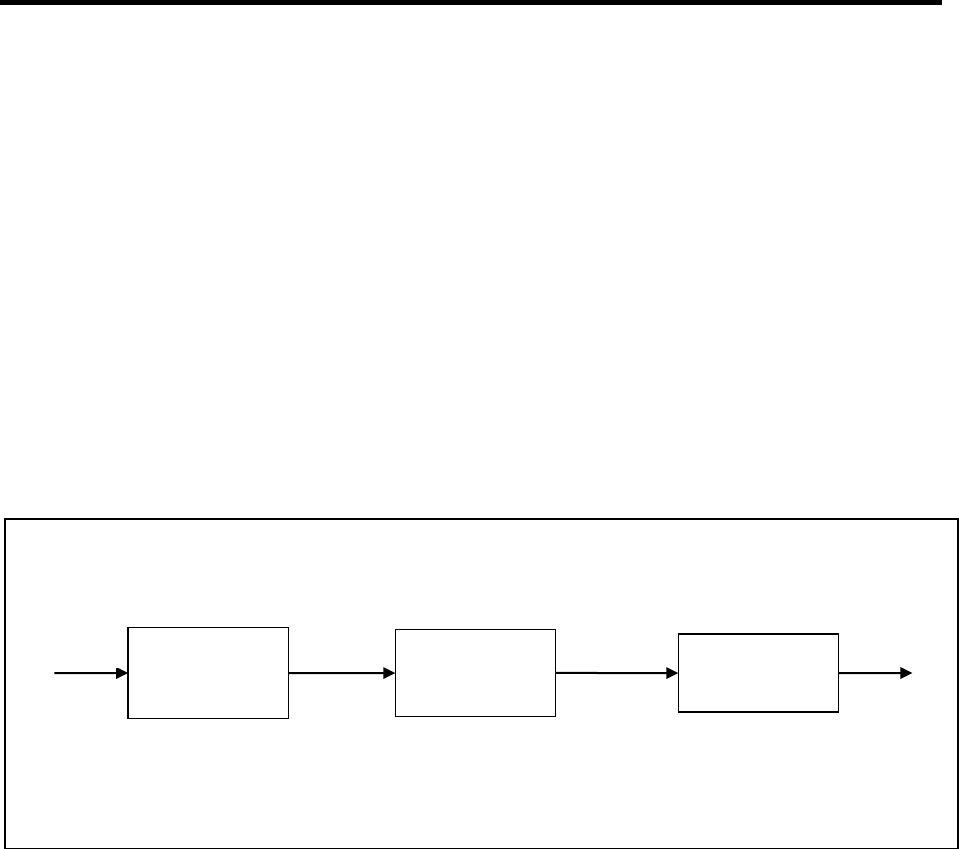
123
the FTP server and writes the file. All embedded DLE characters are stripped so that
only the next character is passed through. When the final ETX character is detected,
FTP-Put endpoint 3 is signaled to close the file and the connection to the FTP server.
Compress/Decompress 15.8.2
The Compress and Decompress endpoints use the zlib compression format to decrease
the size of a file prior to sending to or receiving from a remote server, thereby reducing
the required bandwidth. For more details about zlib, please visit the web site
http://zlib.net.
Example'1'
The following compression example defines three endpoints and two bridges to send a
compressed tag file to a remote FTP server. Tag 1 contains the data to be sent.
Note: The Tag-Read endpoint1 is defined last because it will trigger the data transfer to
begin when it is created.
At$eserver=5,ftp.example.com,,”myid”,”mypwd”
at$ftpopen=5,0,00320001
at$endpoint=2,24
at$endpoint=3,11,5,"TestFile.zlib"
at$bridgecreate=1,1,2,1
at$bridgecreate=2,2,3,1
at$endpoint=1,15,1
Tag Read endpoint 1 reads data from tag 1 and passes it through Bridge 1 to Compress
endpoint 2. The tag data is compressed and passed through Bridge 2 to FTP-Put
endpoint 3, which opens a connection to the FTP server and writes the file. When all
data from tag1 has been compressed and passed through, FTP-Put endpoint 3 is
signaled to close the file and the connection to the FTP server.
Bridge 2
Bridge 1
Compress
Endpoint2
Tag Read
Endpoint1
FTP Put
Endpoint3
Tag 1
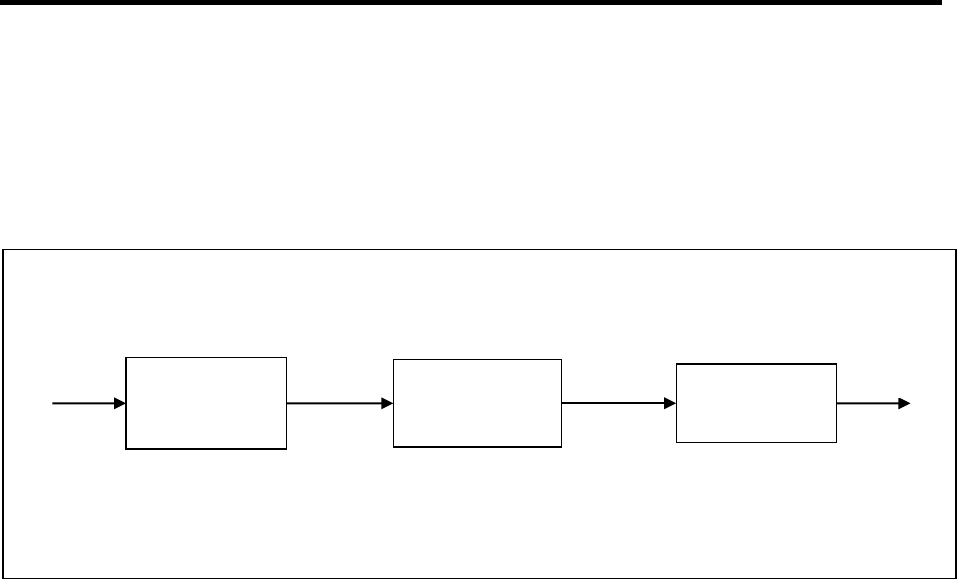
124
Example'2'
This example of decompression is the reverse of the previous example. It defines three
endpoints and two bridges to receive a compressed file from a remote FTP server,
decompress it, and write it to Tag 2.
Note: The FTP-Read endpoint1 is defined last because it will trigger the data transfer to
begin when it is created.
At$eserver=5,ftp.example.com,,”myid”,”mypwd”
at$endpoint=3,14,2
at$endpoint=2,25
at$bridgecreate=1,1,2,1
at$bridgecreate=2,2,3,1
at$endpoint=1,10,5,"TestFile.zlib"
FTP Read endpoint 1 reads data from the FTP server and passes it through Bridge 1 to
Decompress endpoint 2. The file data is decompressed and passed through Bridge 2 to
Tag Write endpoint 3, which writes the file to tag 2. When all data from the FTP server
file has been received, the connection to the remote server is closed. When all data is
decompressed, and passed through, Tag Write endpoint 3 is signaled to close the tag
file.
Bridge 2
Bridge 1
Decompress
Endpoint2
FTP Read
Endpoint1
Tag Write
Endpoint3
Tag 2

125
16 AT Parser Endpoints
AT Parser endpoints handle commands that arrive from an upstream endpoint. The
end of a command must be indicated by a semicolon (;), <CR> or <LF>. After
processing the command, the response message is sent back to the upstream
endpoint. The command echo mode can be configured off or on.
Line editing with a backspace (BS) can be enabled or disabled. If the source of the AT
command is from a human typing text, the edit mode can be enabled. But if the AT
commands are coming from a pre-processed source, such as SMS or email, the edit
mode can be disabled.
16.1 Events
The events below are generated by AT Parser Endpoints. They may be used to trigger
any action in the software that accepts events.
See Table 7.1 for the Event Types. The event object Id is the endpoint Id.
Name
Number
Description
LINE
1
A command line (possibly containing
concatenated commands) has been received.
START
2
A single command has started execution.
DONE
3
A single command completed successfully.
ERROR
4
An error occurred.
16.2 ASCII Commands
These are AT commands used to create an “endpoint” which defines a connection used
by the “Pass Through” routing subsystem. The Endpoint settings can be set or read.
The general part of the AT$ENDPOINT command is described in section 15.4.1. This
section describes the portion of the command that is specific to AT Parser endpoints.
Action Command 16.2.1
The following shows the command (in bold) to configure settings for AT Parser
Endpoints. An optional parameter may be skipped by entering a comma as its
placeholder.
AT$ENDPOINT=<endpoint>,<protocol=18>[,<echo>[,<allowEdit>[,<bufferSize>
[,<fwdTimeout>[,<fwdDataSize>[,<fwdCtrlChar>]]]]]]
$ENDPOINT: ”<deviceId>”,<status>

126
(OK | ERROR)
For Deletion:
Specifying only the Endpoint ID deletes the endpoint.
AT$ENDPOINT=<endpointId>
$ENDPOINT: ”<deviceId>”,<status>
(OK | ERROR)
Read Command 16.2.2
The following shows the command (in bold) to query the Endpoint settings. All defined
records are displayed.
AT$ENDPOINT?
For AT Parser endpoints:
$ENDPOINT: ”<deviceId>”,<status>,<endpointId>,<protocol=18>,<echo>,<allowEdit>,
<bufferSize>,<fwdTimeout>,<fwdDataSize>,<fwdCtrlChar>
…<more records>…
(OK | ERROR)
!!!!Parameters!
Parameter
Description
<deviceId>
The Id of the modem.
<status>
The status of the command.
<endpoint Id>
The Id of the endpoint.
<protocol>
The type of endpoint being created.
18 = AT Parser
(See section 15 for full protocol ID table)
<echo>
Indicates whether the command is echoed.
0 = No echo
1 = Echo each character as it arrives (default).
2 = Wait for complete command, then echo.
<allowEdit>
Allow Backspace to line edit:
0 = Do not allow. The BS character will be ignored.
1 = Allow editing. BS erases the previous character (default).
<bufferSize>
Size of the data buffer (10 – 100000 bytes). Default=5K
<fwdTimeout>
Time to wait before forwarding data (10 – 3600000 msec).
Default=300msec
<fwdDataSize>
Number of bytes to buffer before forwarding data (10 –
100000). Default=1K
<fwdCtrlChar>
A control character to cause data to be forwarded. Enter a

127
decimal value (0 – 31). For example, ETX = 3. (256+ =
disabled). Default=13 <CR>
<status>
Description
0
Success
1012
Error saving data to NVM
1050
Invalid Parameter Value
1090
Invalid Endpoint Id
1093
Invalid Protocol
other
Refer to Appendix A
Example 16.2.3
The following example shows a bridge between a serial endpoint and an AT Parser
endpoint
AT$ENDPOINT=2,18
AT$BRIDGECREATE=1,1,2,2
AT$ENDPOINT=1,3,1
17 SMS Endpoints
SMS endpoints may be used to exchange data between SMS messages and other
endpoints. Incoming SMS message data is passed through to the bridged endpoint.
And data that is received from another endpoint is sent out as an SMS message to the
destination phone number.
The destination phone number is determined by the source of the previous incoming
SMS message. If an incoming SMS message has not been received yet, then the first
configured phone number is used. In this case, the number may not contain any
wildcards.
To add some security and prohibit unauthorized SMS messages to the device, a PIN
code can be required. The PIN code then needs to be included as the first characters in
every SMS message.
The endpoint can also be configured to only process SMS messages from up to three
phone numbers. The configured phone numbers may contain wildcard characters, with
“*” matching 0 or more characters, and “?” matching exactly one character. When
specifying phone numbers, omit the country code. The device will remove the “+1” from
all incoming SMS phone numbers. Only US numbers are supported.
SMS messages from all other phone numbers are ignored by the endpoint system and
handled normally by the modem.
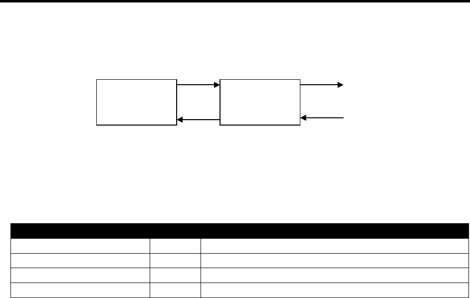
128
17.1 Endpoint Configuration
SMS Endpoint
17.2 Events
These events are generated by SMS endpoints. The EventType is 104. The ObjectId
for the event is the Endpoint ID. See section 7 for more about events.
Name
EventId
Description
MESSAGE_SENT
1
A message was sent out successfully.
MESSAGE_RECEIVED
2
An incoming SMS message was received.
MESSAGE_ERROR
3
A sending error occurred.
SEND_DONE
4
Message was sent to all destinations.
17.3 ASCII Commands
AT command used to create an “endpoint” which defines a connection used by the
“Pass Through” routing subsystem. The Endpoint settings can be set or read.
Action Command 17.3.1
The following shows the command (in bold) to configure settings for an SMS Endpoint.
An optional parameter may be skipped by entering a comma as its placeholder. For
example, to create SMS endpoint 1 with default values except for setting <fwdCtrlChar>
to 13, enter AT$ENDPOINT=1,4,,,,,,,,,13
For Creating an SMS endpoint:
AT$ENDPOINT=<endpoint>,<protocol=4>[,<mode>[,<pinCode>[,<smsPhoneNum1
>
[,<smsPhoneNum2>[,<smsPhoneNum3>[,<endMsg>[,<bufferSize>[,<fwdTimeout>
[,<fwdDataSize> [,<fwdCtrlChar>]]]]]]]]]]
$ENDPOINT: ”<deviceId>”,<status>
(OK | ERROR)
For Deletion:
Specifying only the Endpoint ID deletes the endpoint.
AT$ENDPOINT=<endpointId>
$ENDPOINT: ”<deviceId>”,<status>
Upstream
Endpoint
SMS
Endpoint

129
(OK | ERROR)
Read Command 17.3.2
The following shows the command (in bold) to query the Endpoint settings. All defined
records are displayed.
AT$ENDPOINT?
If SMS:
$ENDPOINT: ”<deviceId>”,<status>,<endpointId>,<protocol=4>,<mode>,<pinCode>,
<smsPhoneNum1>,<smsPhoneNum2>,<smsPhoneNum3>,<endMsg>,<bufferSize>,
<fwdTimeout>,<fwdDataSize>,<fwdCtrlChar>
…<more records>…
(OK | ERROR)
!!!Parameters!
Parameter
Description
<deviceId>
The Id of the modem.
<status>
The status of the command.
<endpoint Id>
The Id of the endpoint (1-49).
<protocol>
The type of endpoint being created.
(See section 15 for full protocol ID table)
<mode>
1 = SMS messages allowed with no checking (default).
2 = SMS messages allowed with valid PIN code.
3 = SMS messages allowed from specified phone numbers
only.
4 = SMS messages allowed with valid PIN and from
specified phone numbers only (same as 2 and 3
combined).
<pinCode>
The string that gives a PIN code to confirm for SMS
authorization (up to 6 chars).
<smsPhoneNum1>
<smsPhoneNum2>
<smsPhoneNum3>
Authorized incoming SMS Phone Numbers (up to 20 chars
each). Wildcards are supported.
Number 1 is the default destination for outgoing SMS
messages prior to the first received SMS message.
<endMsg>
Specifies how incoming SMS messages should be
terminated:
0 = Nothing is appended (default).
1 = <CR> is appended to each incoming message.
2 = <CR><LF> are appended to each incoming message.
3 = A semicolon (;) is appended to each incoming

130
message.
<bufferSize>
Size of the data buffer (10 – 100000 bytes). Default=1600
<fwdTimeout>
Time to wait before forwarding data (10 – 3600000 msec).
Default=750msec
<fwdDataSize>
Number of bytes to buffer before forwarding data (10 –
100000). Default=160
<fwdCtrlChar>
A control character to cause data to be forwarded. Enter a
decimal value (0 – 31). For example, ETX = 3. (256+ =
disabled). Default=disabled
<status>
Description
0
Success
1002
Invalid IP address
1008
Invalid Port
1012
Error saving data to NVM
1050
Invalid Parameter Value
1055
Invalid EServer Id
1090
Invalid Endpoint Id
1093
Invalid mode parameter.
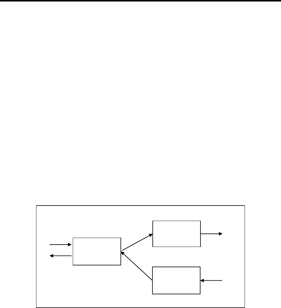
131
18 FTP Endpoints
FTP endpoints are available to read or write files on an FTP server. The remote server
is configured with the EServer commands.
When an FTP Put endpoint receives data from another endpoint, it connects to the FTP
server and appends the data to the end of the file on the server. For FTP-Put only, a
server connection must first be opened with AT$FTPOPEN before the Put can start.
When finished, other FTP operations (such as AT$FTPREN) may be performed, or the
connection can be closed with AT$FTPCLOSE.
The FTP-Get does not currently have this requirement. The FTP-Get automatically
opens its server connection, performs the Get, then closes its connection. An FTP Get
endpoint connects to the FTP server upon receiving the configured event. The file is
downloaded and the data is passed to another endpoint.
18.1 Configurations
In order to achieve bi-directional communications with FTP you must setup two separate
endpoints: one to send data (PUT) and one to receive data (GET).
FTP Endpoints Figure 2.
18.2 Events
The events below are generated by FTP Endpoints. They may be used to trigger any
action in the software that accepts events.
FTP GET 18.2.1
See Table 7.1 for the Event Types.
Read File
Write File
Bridge 2
Bridge 1
FTP PUT
Endpoint
FTP GET
Endpoint
Serial
Endpoint

132
Name
Number
Description
Session Open
1
Session with FTP Server was opened.
Data Open
2
Data channel opened with the server.
File Received
3
Complete File has been received.
General Error
4
A general error occurred.
File Error
5
File not found.
Login Error
6
Username or password error
Session Closed
7
Session with HTTP Server was closed
FTP PUT 18.2.2
See Table 7.1 for the Event Types.
Name
Number
Description
Data Open
2
Data channel opened with the server.
File Sent
3
File has been sent successfully.
General Error
4
A general error occurred.
18.3 ASCII Commands
AT command used to create an “endpoint” which defines a connection used by the
“Pass Through” routing subsystem. The Endpoint settings can be set or read.
Action Command 18.3.1
The following shows the command (in bold) to configure settings for a FTP Endpoints.
An optional parameter may be skipped by entering a comma as its placeholder. For
example, to create FTP Get endpoint 1 with default values except for setting
<fwdCtrlChar> to 13, enter AT$ENDPOINT=1,10,5,”index.html”,,,,,13
You must define an Endpoint server and pass the ID of that server to the FTP endpoint
when it is created.
For FTP Get:
AT$ENDPOINT=<endpointId>,<protocol=10>,<eServerId>,"<filename>”[,<localPor
t>
[,<eventFilter>[,<bufferSize>[,<fwdTimeout>[,<fwdDataSize>[,<fwdCtrlChar>]]]]]]
$ENDPOINT: ”<deviceId>”,<status>
(OK | ERROR)
For FTP Put:

133
AT$ENDPOINT=<endpointId>,<protocol=11>,<eServerId>,"<filename>”[,<localPor
t> [,<bufferSize>[,<fwdTimeout>[,<fwdDataSize>[,<fwdCtrlChar>]]]]]
$ENDPOINT: ”<deviceId>”,<status>
(OK | ERROR)
For Deletion:
Specifying only the Endpoint ID deletes the endpoint.
AT$ENDPOINT=<endpointId>
$ENDPOINT: ”<deviceId>”,<status>
(OK | ERROR)
Read Command 18.3.2
The following shows the command (in bold) to query the Endpoint settings. All defined
records are displayed.
AT$ENDPOINT?
If FTP Get:
$ENDPOINT:
”<deviceId>”,<status>,<endpointId>,<protocol=10>,<eServerId>,”<filename>”,
<localPort>,<eventFilter>,<bufferSize>,<fwdTimeout>,<fwdDataSize>,<fwdCtrlChar>
If FTP Put:
$ENDPOINT:
”<deviceId>”,<status>,<endpointId>,<protocol=11>,<eServerId>,”<filename>”,
<localPort>,<bufferSize>,<fwdTimeout>,<fwdDataSize>,<fwdCtrlChar>
…<more records>…
(OK | ERROR)
!!!!Parameters!
Parameter
Description
<deviceId>
The Id of the modem.
<status>
The status of the command.
<endpoint Id>
The Id of the endpoint (1-49).
<protocol>
The type of endpoint being created.
(See section 15 for full protocol ID table)
<bufferSize>
Size of the data buffer (10 – 100000 bytes). Default=7250
<fwdTimeout>
Time to wait before forwarding data (10 – 3600000 msec).
Default=250msec
<fwdDataSize>
Number of bytes to buffer before forwarding data (10 –
100000). Default=1450

134
<fwdCtrlChar>
A control character to cause data to be forwarded. Enter a
decimal value (0 – 31). For example, ETX = 3. (256+ =
disabled). Default=disabled
eServerId
Endpoint Server Id. The Eserver contains the server’s IP
address, port, username, and password.
Note that for HTTP endpoints, the eserver IP address must
include the protocol prefix, such as “http//:”!
<filename>
File path and name.
<localPort>
Client’s local port.
0 = The modem will assign a value (default).
1 – 65535 = User defined port. (Not supported)
<eventFilter>
Event Filter Id. This defines the events that trigger the
start of a file download. A null or value=99 specifies
“immediate” (default).
<status>
Description
0
Success
1002
Invalid IP address
1008
Invalid Port
1012
Error saving data to NVM
1090
Invalid Endpoint Id
1050
Invalid Parameter Value
1055
Invalid EServer Id
1093
Invalid Protocol
18.4 GET Example
The following example shows a bridge between an FTP server and Tag 1. The file is
fetched immediately from the server and stored in tag 1.
Note: The FTP Get endpoint is defined last so the “immediate” fetch has all the other
objects ready to go.
AT$ESERVER=5,ftp.example.com,,"myid","mypwd"
AT$ENDPOINT=2,14,1
AT$BRIDGECREATE=1,1,2,1
AT$ENDPOINT=1,10,5,"somefile.dwl"
18.5 PUT Example
The following example shows a bridge between a USB serial endpoint and an FTP
server. Input data to the serial port is sent out the FTP Put endpoint and written in a file
on the FTP server.
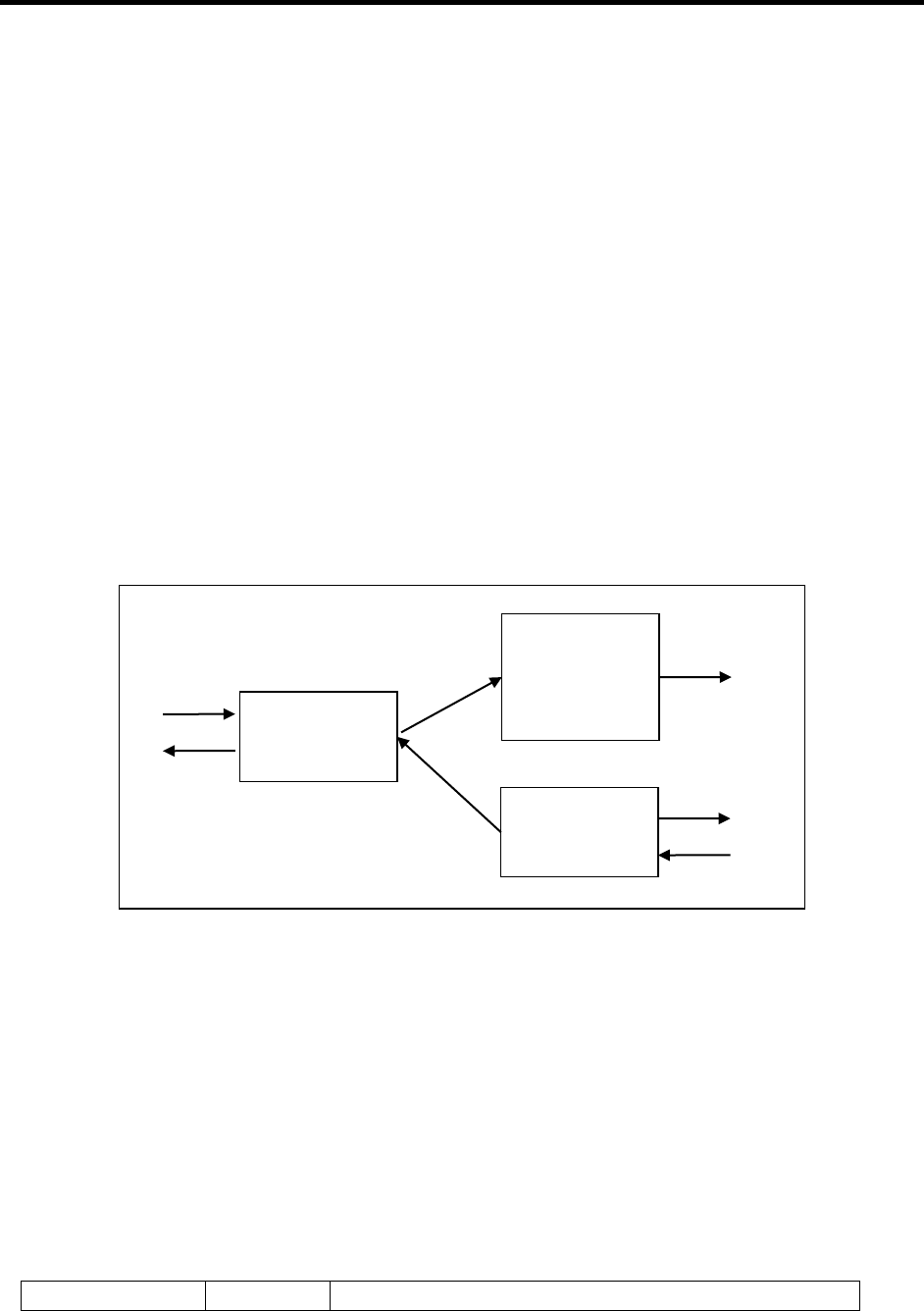
135
AT$ESERVER=5,ftp.example.com,,"myid","mypwd"
AT$FTPOPEN=5,0,00320001
AT$ENDPOINT=1,3,3
AT$ENDPOINT=2,11,5,"myfile.txt"
AT$BRIDGECREATE=1,1,2,1
19 HTTP Endpoints
There are three HTTP Endpoints available, GET, PUT, and POST. These endpoints are
used to receive and send files or data with an HTTP Server.
19.1 Configurations
In order to achieve bi-directional communications with HTTP you must setup two
separate endpoints. One to send data (either PUT or POST) and one to receive data
(GET).
HTTP Endpoints Figure 3.
19.2 Events
The events below are generated by HTTP Endpoints. They may be used to trigger any
action in the software that accepts events.
HTTP GET 19.2.1
See Section 7.1 for the Event Types.
Name
Number
Description
Server
Respons
Bridge 2
Bridge 1
Poll Server
HTTP
POST or
HTTP PUT
Endpoint
HTTP GET
Endpoint
Serial
Endpoint

136
Session Open
1
Session with HTTP Server was opened.
Data Open
2
Data channel opened with the server.
File Received
3
The file has been received.
Error
4
An Error occurred
Session Closed
5
Session with HTTP Server was closed
HTTP PUT 19.2.2
See Section 7.1 for the Event Types.
Name
Number
Description
Session Open
1
Session with HTTP Server was opened.
Data Open
2
Data channel opened with the server.
File Sent
3
The file has been sent.
Error
4
An Error occurred
Session Closed
5
Session with HTTP Server was closed
HTTP POST 19.2.3
See Section 7.1 for the Event Types.
Name
Number
Description
Session Open
1
Session with HTTP Server was opened.
Data Open
2
Data channel opened with the server.
File Sent
3
The POST has been Sent.
Error
4
An Error occurred
Session Closed
5
Session with HTTP Server was closed
19.3 ASCII Commands
AT command used to create an “endpoint” which defines a connection used by the
“Pass Through” routing subsystem. The Endpoint settings can be set or read.
Action Command 19.3.1
The following shows the command (in bold) to configure settings for HTTP Endpoints.
An optional parameter may be skipped by entering a comma as its placeholder. For
example, to create HTTP Get endpoint 1 with default values except for setting
<eventFilter> to 1 and <fwdCtrlChar> to 13, enter
AT$ENDPOINT=1,5,3,”index.html”,,1,,,,13

137
When defining an HTTP Post connection, the “protocol”, and “URL” fields are required.
Optionally, a “username” and “password” may be specified, if required by the HTTP
server. One or more header,value pairs may be added at the end of the command line.
For HTTP Get:
AT$ENDPOINT=<endpointId>,<protocol=5>,<eServerId>,"<filename>”[,<localPort
> [,<eventFilter>[,<bufferSize>[,<fwdTimeout>[,<fwdDataSize>[,<fwdCtrlChar>
[,<headerList>]]]]]]]
$ENDPOINT: ”<deviceId>”,<status>
(OK | ERROR)
For HTTP Put:
AT$ENDPOINT=<endpointId>,<protocol=6>,<eServerId>,"<filename>”[,<localPort
> [,<bufferSize>[,<fwdTimeout>[,<fwdDataSize>[,<fwdCtrlChar>[,<headerList>]]]]]]
$ENDPOINT: ”<deviceId>”,<status>
(OK | ERROR)
For HTTP Post:
AT$ENDPOINT=<endpointId>,<protocol=7>,<http_ver>,”<url>”[,”<username>”
[,”<password>”[,<localPort>[,<bufferSize>[,<fwdTimeout>[,<fwdDataSize>
[,<fwdCtrlChar>[,<headerList>]]]]]]]]
$ENDPOINT: ”<deviceId>”,<status>
(OK | ERROR)
For Deletion:
Specifying only the Endpoint ID deletes the endpoint.
AT$ENDPOINT=<endpointId>
$ENDPOINT: ”<deviceId>”,<status>
(OK | ERROR)
Read Command 19.3.2
The following shows the command (in bold) to query the Endpoint settings. All defined
records are displayed.
AT$ENDPOINT?
If HTTP Get:
$ENDPOINT:
”<deviceId>”,<status>,<endpointId>,<protocol=5>,<eServerId>,”<filename>”,
<localPort>,<eventFilter>,<headerList>,<bufferSize>,<fwdTimeout>,<fwdDataSize>,
<fwdCtrlChar>
If HTTP Put:

138
$ENDPOINT:
”<deviceId>”,<status>,<endpointId>,<protocol=6>,<eServerId>,”<filename>”,
<localPort>,<headerList>,<bufferSize>,<fwdTimeout>,<fwdDataSize>,<fwdCtrlChar>
If HTTP Post:
$ENDPOINT: ”<deviceId>”,<status>,<endpointId>,<protocol=7>,<http_ver>,”<url>”,
”<username>”,”<password>”,<localPort>,<headerList>,<bufferSize>,<fwdTimeout>,<fwd
DataSize>,<fwdCtrlChar>
…<more records>…
(OK | ERROR)
!!!Parameters!
Parameter
Description
<deviceId>
The Id of the modem.
<status>
The status of the command.
<endpoint Id>
The Id of the endpoint (1-49).
<protocol>
The type of endpoint being created.
(See section 15 for full protocol ID table)
<bufferSize>
Size of the data buffer (10 – 100000 bytes). Default=7250
<fwdTimeout>
Time to wait before forwarding data (10 – 3600000 msec).
Default=250msec
<fwdDataSize>
Number of bytes to buffer before forwarding data (10 –
100000). Default=1450
<fwdCtrlChar>
A control character to cause data to be forwarded. Enter a
decimal value (0 – 31). For example, ETX = 3. (256+ =
disabled). Default=disabled
<http_ver>
HTTP version:
0 = Version 1.0
1 = Version 1.1
<url>
URL to the HTTP Post server and handler file, such as
http://www.example.com:1234/myfolder/myhandler.ext
The IP Address portion may be entered in either a numeric
form, such as “203.0.113.1”, or a DNS name, such as
“www.example.com”. The port value is optional
(default=80).
<username>
User name for login
<password>
Password for login
<localPort>
Client’s local port.
0 = The modem will assign a value (default).
1 – 65535 = User defined port. (Not supported)
<headerList>
Each HTTP header is entered as a “name”,”value” pair.

139
Do not include a colon after the name. More pairs can be
added, separated by commas.
eServerId
Endpoint Server Id. The Eserver contains the server’s IP
address, port, username, and password.
Note that for HTTP endpoints, the eserver IP address must
include the protocol prefix, such as “http//:”!
<filename>
File path and name.
<eventFilter>
Event Filter Id. This defines the events that trigger the
start of a file transfer. A null or value=99 specifies
“immediate” (default).
<status>
Description
0
Success
1002
Invalid IP address
1008
Invalid Port
1012
Error saving data to NVM
1050
Invalid Parameter Value
1055
Invalid EServer Id
1090
Invalid Endpoint Id
1093
Invalid Protocol
19.4 Get Example
The following example shows a bridge between serial port 1 and an HTTP server at
Google.com. The default page is fetched every 30 seconds and the text is routed out
serial port 1. The example below is using event Timer 1 expiration, 00020103, as a
trigger for the HTTP GET to happen.
Note: The serial endpoint is defined last so all the AT commands can be entered on
serial port 1 before it is switched into data mode by its endpoint creation.
at$eventfilter=1,00020103 // Define event filter
at$timerstart=1,300,00020103 // Restart timer every time the timer expires
at$timerstart=1,0 // This starts the timer the first time
at$eserver=3,"http://www.example.com"
at$endpoint=1,5,3,"index.html",,1,,,,,Accept,text/html //1 is the event filter
at$bridgecreate=1,1,2,2
at$endpoint=2,3,1 // Serial endpoint
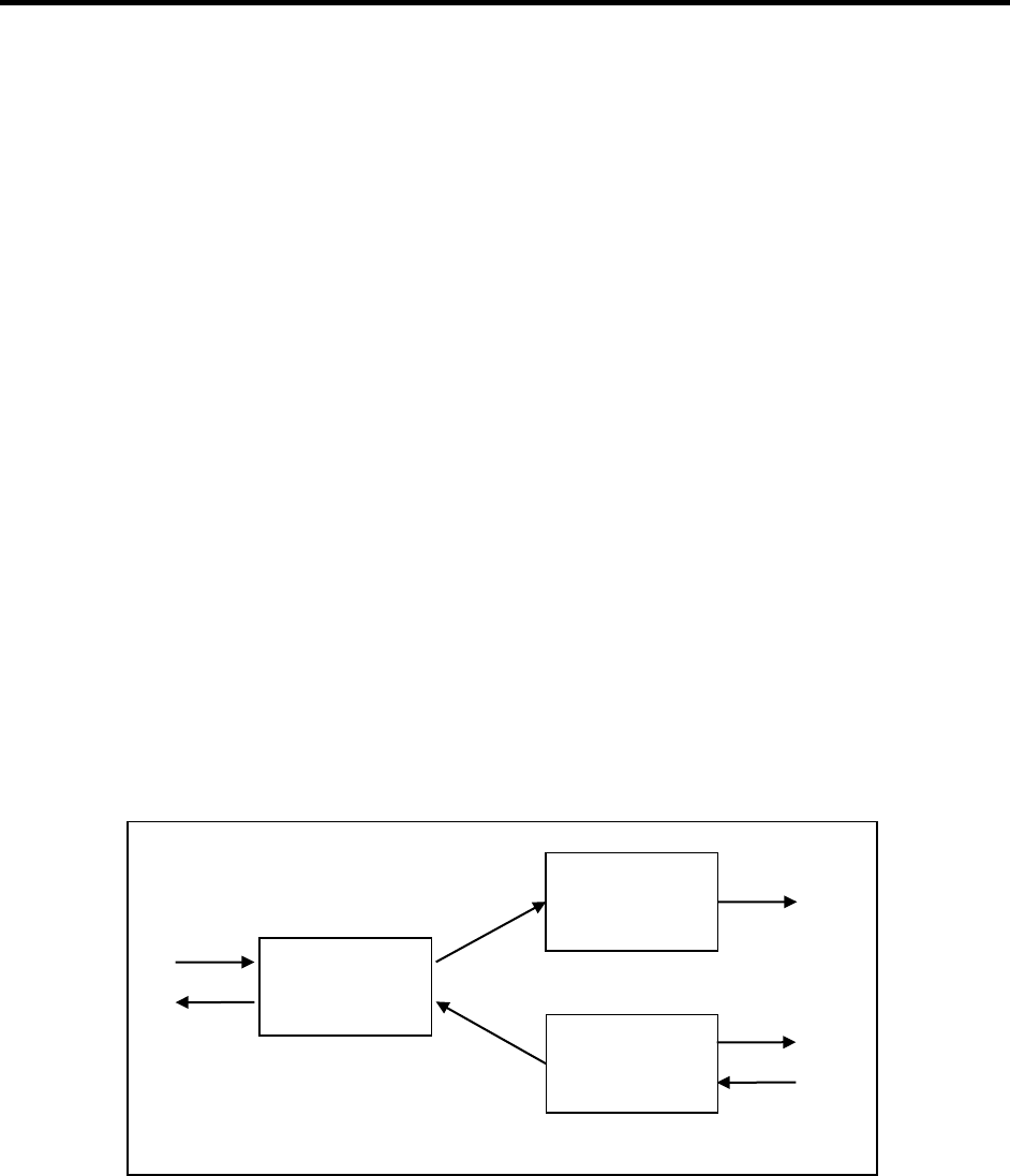
140
19.5 Put Example
The following example shows a bridge between serial port 1 and an HTTP server that
accepts Put data on port 2025. The outgoing text is entered over serial port 1 and
transferred to the HTTP server to a file named “MyFile.txt”.
AT$ESERVER=4,"http://203.0.113.1",2025
AT$ENDPOINT=1,6,4,"MyFile.txt",,,,,,Accept,text/html
AT$ENDPOINT=2,3,1
AT$BRIDGECREATE=1,2,1,1
20 Email Endpoints
Two types of endpoints allow the user to send and receive email. The SMTP endpoint
sends email to the server. The POP endpoint polls the server periodically to receive
email when it is available. Once received, the email can be left on the server or deleted
at the server.
20.1 Configurations
Email endpoints send and receive email via other bridged endpoints. The SMTP
endpoint supports data in the downstream direction, while the POP endpoint transfers
data in the upstream direction (see Figure 4).
Email Endpoints Figure 4.
The SMTP and POP servers are configured separately using the Endpoint Server
commands. Then each email endpoint is defined , including a reference to the Email
Server Id.
Bridge 2
Bridge 1
Poll Server
SMTP
Endpoint
POP
Endpoint
Serial
Endpoint

141
20.2 Events
The events below are generated by HTTP Endpoints. They may be used to trigger any
action in the software that accepts events.
POP Endpoint 20.2.1
See section 7.1 for the Event Type.
Name
Number
Description
Session Open
1
Session with POP Server was opened
Session Closed
2
Session with POP Server was closed
List Received
3
The email list has been received
Email Received
4
An email has been received and passed on to
the next endpoint in the chain.
Email Deleted
5
An email has been deleted from the server.
SMTP Endpoint 20.2.2
Event Type: 108
20.3 AT$ENDPOINT
The AT command used to create an email endpoint is part of the general endpoint
facility. The syntax and parameters that are unique to email endpoints are shown in the
following sections. Endpoint settings can be set or read.
Action Command 20.3.1
The following shows the command (in bold) to configure settings for an Email Endpoint.
For SMTP Email:
AT$ENDPOINT=<endpointId>,<protocol=8>,<eServerId>,<emailHdrId>
[,<bufferSize>[,<fwdTimeout>[,<fwdDataSize>[,<fwdCtrlChar>]]]]
$ENDPOINT: ”<deviceId>”,<status>
(OK | ERROR)
For POP Email:
AT$ENDPOINT=<endpointId>,<protocol=9>,<eServerId>[,<eventFilter>
[,<deleteOnServer>[,<fwdHeaders>[,<bufferSize>[,<fwdTimeout>[,<fwdDataSize>
[,<fwdCtrlChar>[,<filterList>]]]]]]]]
$ENDPOINT: ”<deviceId>”,<status>
(OK | ERROR)
For Deletion:

142
Specifying only the Endpoint ID deletes the endpoint.
AT$ENDPOINT=<endpointId>
$ENDPOINT: ”<deviceId>”,<status>
(OK | ERROR)
Read Command 20.3.2
The following shows the command (in bold) to query the Endpoint settings. All defined
records are displayed.
AT$ENDPOINT?
If SMTP Email:
$ENDPOINT:
”<deviceId>”,<status>,<endpointId>,<protocol=8>,<eServerId>,<emailHdrId>,
<bufferSize>,<fwdTimeout>,<fwdDataSize>,<fwdCtrlChar>
If POP Email:
$ENDPOINT:
”<deviceId>”,<status>,<endpointId>,<protocol=9>,<eServerId>,<eventFilter>,
<deleteOnServer>,<fwdHeaders>,<filterList>,<bufferSize>,<fwdTimeout>,<fwdDataSize
>, <fwdCtrlChar>
…<more records>…
(OK | ERROR)
Parameters
Parameter
Description
<deviceId>
The Id of the modem.
<status>
The status of the command.
<endpoint Id>
The Id of the endpoint (1-49).
<protocol>
The type of email endpoint being created:
8 = SMTP
9 = POP
eServerId
Endpoint Server Id. The EServer contains the server’s IP
address, port, username, and password.
emailHdrId
Email Header Id. The Email settings contain the sender
and recipient information.
<deleteOnServer>
0 = Leave POP email on server.
1 = POP email will be deleted from server after being read
(default).
<fwdHeaders>
Future feature, not currently supported.
0 = Header will not be forwarded (default).
1 = Headers will be forwarded along with email body.

143
<filterList>
Future feature, not currently supported.
Only email from these addresses will be forwarded. All
other email will be ignored. If the list is empty, all email will
be forwarded.
Multiple email addresses can be entered, separated with
commas.
<eventFilter>
Event Filter Id. This defines the events that trigger the
start of a file transfer. A null or value=99 specifies
“immediate” (default).
<status>
Description
0
Success
1012
Error saving data to NVM
1050
Invalid Parameter Value
1090
Invalid Endpoint Id
1093
Invalid Protocol
20.4 Email Header
This section describes the commands available to define and query Email Headers for
use by SMTP Email Endpoints. Parameters include the sender’s name and email
address, and the recipients and subject. Once defined, a new SMTP Endpoint can be
defined that references the Email Header by its Id.
The following command is supported:
• AT$EMAIL – Command to administer Email Headers.
AT$EMAILHDR 20.4.1
This is an AT command to administer SMTP Email Headers.
Action'Command'
The following shows the command (in bold) to create an Email Header.
AT$EMAILHDR=<emailHdrId>,"<senderEmail>",["<senderName>"],"<toList>"[,"<c
cList>" [,"<bccList>"[,"<subject>"]]]
$EMAILHDR: ”<deviceId>”,<status>
(OK | ERROR)
Specifying only the <emailHdrId> deletes that Email Header.

144
Read'Command'
The following shows the command (in bold) to query the SMTP Email Header. All
defined records are displayed.
AT$EMAILHDR?
$EMAILHDR: ”<deviceId>”,<status>,<emailHdrId>,"<senderEmail>","<senderName>",
"<toList>","<ccList>","<bccList>","<subject>"
…<more records>…
(OK | ERROR)
!!!Parameters!
Parameter
Description
<deviceId>
The ID of the modem.
<status>
The status of the command.
<emailHdrId>
Email Header Id (1-5)
<senderEmail>
Sender’s Email Address
<senderName>
Sender’s Name
<toList>
To-List
<ccList>
CC-List
<bccList>
BCC-List
<subject>
Subject
<status>
Description
0
Success
1012
Error saving data to NVM
1050
Invalid parameter value
1056
Invalid Email Header Id
20.5 Example
The following example defines three endpoints and two bridges for sending out mail to
an SMTP server and receiving email from a POP server. The text for the outgoing email
is entered over serial port 1. And the incoming POP email data is also output on serial
port 1. Refer to Figure 4 for a diagram of the configuration. The POP server will be
queried every 600 seconds (10 minutes) and all messages will be left on the server (no
delete).
Note: The serial endpoint is defined last so all the AT commands can be entered on
serial port 1 before it is switched into data mode by its endpoint creation.
AT$ESERVER=1,"smtp-
server.example.com",25,"myemailid@example.com","mypasswd",2

145
AT$EMAILHDR=1,"myemailid@example.com","My Name","someone@example.com",,,"My
Subject"
AT$ENDPOINT=1,8,1,1
AT$ESERVER=2,"pop-server.example.com",110,"myemailid@example.com","mypasswd"
AT$ENDPOINT=2,9,2,600,0,0
AT$BRIDGECREATE=1,3,1,1
AT$BRIDGECREATE=2,2,3,1
AT$ENDPOINT=3,3,1

146
21 Offline Data Mode
The software’s offline data mode endpoint and associated AT commands provide the
ability to read and write binary data to an offline data mode endpoint using AT
commands. By using a bridge to connect the offline data mode endpoint to any other
software endpoint, the offline data mode AT commands can be used to easily and
reliably send and receive data to/from any software endpoint using AT commands. The
offline data mode endpoint has several advantages:
• It may be used concurrently with other AT commands.
• It intrinsically supports messages (file-oriented or packetized data).
It supports flow control, and provides events to handle flow control so polling is not
required.
21.1 Events
The events below are generated by Offline Data Mode Endpoints. They may be used to
trigger any action in the software that accepts events.
Name
Number
Description
Data Available
1
RX buffer has data available
Space
Available
2
TX buffer has free space
21.2 AT$ENDPOINT
The AT command used to create an email endpoint is part of the general endpoint
facility. The syntax and parameters that are unique to email endpoints are shown in the
following sections. Endpoint settings can be set or read.
Action Command 21.2.1
The following shows the command (in bold) to configure settings for an Offline Data
Mode Endpoint.
AT$ENDPOINT=<endpointId>,<protocol=26>[,<bufferSize>[,<fwdTimeout>[,<fwdD
ataSize>[,<fwdCtrlChar>]]]]
$ENDPOINT: ”<deviceId>”,<status>
(OK | ERROR)
For Deletion:
Specifying only the Endpoint ID deletes the endpoint.
AT$ENDPOINT=<endpointId>

147
$ENDPOINT: ”<deviceId>”,<status>
(OK | ERROR)
Read Command 21.2.2
The following shows the command (in bold) to query the Endpoint settings. All defined
records are displayed.
AT$ENDPOINT?
$ENDPOINT:
”<deviceId>”,<status>,<endpointId>,<protocol=26>,<bufferSize>,<fwdTimeout>,<fwdDat
aSize>,<fwdCtrlChar>
…<more records>…
(OK | ERROR)
Parameters
Parameter
Description
<deviceId>
The Id of the modem.
<status>
The status of the command.
<endpoint Id>
The Id of the endpoint (1-49).
<protocol>
The type of email endpoint being created:
26 = Offline Data Mode
<bufferSize>
Size of the data buffer (10 – 100000 bytes). Default=7250
<fwdTimeout>
Time to wait before forwarding data (10 – 3600000 msec).
Default=250msec
<fwdDataSize>
Number of bytes to buffer before forwarding data (10 –
100000). Default=1450
<fwdCtrlChar>
A control character to cause data to be forwarded. Enter a
decimal value (0 – 31). For example, ETX = 3. (256+ =
disabled). Default=disabled
21.3 AT$EPWRITE
Writes data directly to an offline data mode endpoint’s output buffer. This data will then
be forwarded over any connected bridges to other software endpoints. The data to write
is hex-encoded so that binary data can be easily written. This will not wait for the data to
be delivered, so if there is not sufficient room in the output buffer, then as much data as
possible is written, and the command returns immediately.

148
Action Command 21.3.1
The following shows the command (in bold) to write data to an Offline Data Mode
Endpoint.
AT$EPWRITE=<endpointId>,< EndOfMessage (0 | 1)>,"<Hex-encoded data>"
$EPWRITE: ”<deviceId>”,<status>,<bytesWritten>
(OK | ERROR)
Parameter
Description
<deviceId>
The Id of the modem.
<status>
The status of the command.
<endpoint Id>
The Id of the endpoint (1-49).
< EndOfMessage >
This is 1 if the data read is the last portion of data in a
packet/message/file, or 0 if it is not.
< bytesWritten >
The number of bytes that were actually written to the
offline data mode endpoint.
'
Examples:'
Write "GET\r\n" to endpoint 1 . All 5 bytes were written successfully:
(
AT$EPWRITE=1,0,"4745540D0A"
$EPWRITE: "327004000672",0,1,5
OK
Write "GET\r\n" to endpoint 1. The endpoint was full, so no data could be written.
(
AT$EPWRITE=1,0,"4745540D0A"
$EPWRITE: "327004000672",0,1,0
OK
Write "1234" to endpoint 1, and mark the data as NOT being the end of a packet so that
we can continue writing the packet later. All four bytes were written successfully.
((
AT$EPWRITE=1,0,"31323334"
$EPWRITE: "327004000672",0,1,4
OK
'
Write "567" to endpoint 1, and mark the data as being the end of a packet. All three
bytes were written successfully, and the entire packet consists of “1234567”, so if the
offline data mode endpoint is bridged to an endpoint that supports packetization, like
UDP, HTTP POST, or FTP, then the packet would be properly delineated.
((
AT$EPWRITE=1,1,"353637"
$EPWRITE: "327004000672",0,1,3
OK

149
21.4 AT$EPREAD
Reads data from an endpoint. The data is read in hex-encoded form so that binary data
can be read. This command will only read data that is currently buffered in the endpoint,
and will not wait on any more data to arrive.
Action Command 21.4.1
The following shows the command (in bold) to read data from an Offline Data Mode
Endpoint.
AT$EPREAD=<endpointId>,<maxBytesToRead>
$EPREAD:
”<deviceId>”,<status>,<endpointId>,<bytesRead>,<EndOfMessage>,”<hexData>”
(OK | ERROR)
Parameter
Description
<deviceId>
The Id of the modem.
<status>
The status of the command.
<endpoint Id>
The Id of the endpoint (1-49).
<EndOfMessage>
This is 1 if the data read is the last portion of data in a
packet/message/file, or 0 if it is not.
<bytesRead>
The number of bytes that were actually read from the
offline data mode endpoint.
<hexData>
The data read from the endpoint. Each byte of data will be
encoded as two hex-digits, all enclosed in quotes. The
total number of hex digits is 2 * Bytes read
Examples:'
(
Read%up%to%256%bytes%from%endpoint%1.%Only%5%bytes%("HELLO")%were%in%the%endpoint's%buffer,%and%
the%five%bytes%are%not%the%end%of%a%packet/message/file:(
AT$EPREAD=1,256
$EPREAD:1,5,0,"48454C4C4F"
OK
(
Read%up%to%256%bytes%from%endpoint%1.%No%data%was%available%in%the%endpoint's%buffer:%
(
AT$EPREAD=1,256
$EPREAD: "327004000672",0,1,0,0,""
OK
(

150
Read%up%to%256%bytes%from%endpoint%1.%Only%5%bytes%("HELLO")%were%in%the%endpoint's%buffer,%and%
these%five%bytes%are%the%last%bytes%in%packet/message/file.%
AT$EPREAD=1,256
$EPREAD: "327004000672",0,1,5,1,"48454C4C4F"
OK
(
21.5 Offline Data Unsolicited Responses:
(
In order to allow the application to use offline data mode without resorting to polling, an
unsolicited response code (URC) is provided which informs the application when an
endpoint's TX buffer is no longer full, and when an endpoint's RX buffer is no longer
empty. Because an application may not want to deal with URCs, choosing to poll
instead, these URCs can be enabled/disabled with an AT command.
$EPDATA:<Endpoint'ID>,<Endpoint'URC'event>'
(
Endpoint URC Event:
0: The endpoint's RX buffer has transitioned from empty to not-empty, or offline data
mode URCs have been enabled and there is data in the endpoint's RX buffer, or the end
of a packet/message/file has been retrieved and there is more data to be read in the RX
buffer.
1: The endpoint's TX buffer has transitioned from full to not-full, or offline data mode
URCs have been enabled, and the endpoint's TX buffer is not full.
Examples:(
Write the last part of a packet/message/file to an endpoint, resulting in it becoming full.
Sometime later, the endpoint’s TX buffer becomes non-full, allowing more data to be
written:
AT$EPWRITE=1,1,"4745540D0A"
$EPWRITE: "327004000672",0,1,2 (only two bytes were enqueued)
OK
(some time passes)
$EPDATA: "327004000672",0,1,1
(now the application can finish writing the rest of the data)
AT$EPWRITE=1,1,"540D0A"
$EPWRITE: "327004000672",0,1,3
OK
Try to read data from an endpoint, but the endpoint is empty. The application waits until
some data is available and then tries again.

151
AT$EPREAD=1,256
$EPREAD: "327004000672",0,1,0,0,""
OK
(some time passes)
$EPDATA: "327004000672",0,1,0
(now the application can read some data)
AT$EPREAD=1,256
$EPREAD: "327004000672",0,1,2,0,"5441"
OK
Read data from an endpoint, and the last two bytes of a packet/message/file are read.
There is more data in the RX buffer, so an $EPDATA URC is generated.
AT$EPREAD=1,256
$EPREAD: "327004000672",0,1,2,1,"0D0A"
OK
$EPDATA: "327004000672",0,1,0

152
22 FTP Operations
The FTP operations allow the user to perform simple file operations on a remote FTP
server, such as Make Directory, Delete Directory, Rename File, and Delete File. The
operations can be performed immediately, or triggered by any system event.
The FTP operations are performed on a remote FTP server that is configured with the
EServer commands. First, a session connection must be opened. All of the FTP
operations must be performed on a connection that is already opened. When finished,
the connection can be closed.
The FTP command parameters are saved to NVM and restored after power cycles, unless
there are no events specified. If the command is entered to be executed immediately, then
nothing is saved to NVM.
22.1 FTP Command Events
The events below are generated by the FTP commands. They may be used to trigger
any action in the software that accepts events.
The Event Type is 55 (0x37) for the FTP Server. The Event ObjectId is the EServerId
value.
Name
EventId
Description
SESSION_OPEN
1
Session opened with the server
SESSION_CLOSE
2
Session closed
MKDIR_DONE
3
MKDIR command completed
CWD_DONE
4
CWD command completed
DELDIR_DONE
5
DELDIR command completed
6
reserved
DEL_DONE
7
DEL command completed
REN_DONE
8
REN command completed
DONE
9
Operation completed
DATA_OPEN
10
Data connection opened with the server
ERROR
11
General error occurred
FILE_ERROR
12
File unavailable
LOGIN_ERROR
13
Username or password error
PEER_CLOSE
14
Peer closed
22.2 FTP Commands
The following commands are supported:

153
• AT$FTPOPEN – Command to open a session connection with a remote FTP server.
• AT$FTPCLOSE – Command to close a session.
• AT$FTPMKDIR – Command to create a new directory.
• AT$FTPCWD – Command to change the current working directory.
• AT$FTPDELDIR – Command to delete a directory.
• AT$FTPDEL – Command to delete a file.
• AT$FTPREN – Command to rename a file.
22.3 AT$FTPOPEN
This command defines the parameters for opening a new session with a remote FTP
server. The server address, port, username, and password are defined by the EServer
commands. The EServer record does not have to exist at the time this command is
entered, but must exist when the operation is triggered and performed.
A session must be opened before any of the other operations can be performed.
Action Command 22.3.1
The following shows the command (in bold) to define the parameters and event labels
for the OPEN:
AT$FTPOPEN=<EServerId>,<eventLabel>[…,<eventLabel>]
$FTPOPEN: “<deviceId>”,<status>
(OK | ERROR)
Immediate Command 22.3.2
If <eventLabel> is 0, then the OPEN operation is performed immediately. The EServer
record must already exist:
AT$FTPOPEN=<EServerId>,0
$FTPOPEN: “<deviceId>”,<status>
(OK | ERROR)
Delete OPEN parameters 22.3.3
If <EServerId> is the only parameter given, then the OPEN parameters for that server
are deleted and removed from NVM:
AT$FTPOPEN=<EServerId>
$FTPOPEN: “<deviceId>”,<status>
(OK | ERROR)

154
Read Command 22.3.4
The following shows the command (in bold) to query the parameters and event labels
for the defined OPEN commands:
AT$FTPOPEN?
$FTPOPEN: “<deviceId>”,<status>,<EServerId>,<eventLabel>…,<eventLabel>
…(list of defined OPEN commands)…
(OK | ERROR)
!!!!Parameters!
Parameter
Description
<deviceId>
The Id of the modem.
<status>
The status of the command.
<EServerId>
The Id of the EServer which specifies the remote FTP server.
<eventLabel>
EventLabel in hex. This defines the event(s) that trigger the
OPEN. There may be from 0 to 10 values. A null or 0 value
specifies “immediate”.
Use the AT$EVENTLABEL command to aid with encoding this
parameter.
<status>
Description
0
Success
1012
Error saving data to NVM.
1050
Invalid Parameter Value.
1052
Record already defined.
1055
Invalid EServer Id.
1066
Invalid event.
other
Refer to the appendix.
Examples 22.3.5
The following example opens a session on the remote server when the device acquires
a GPRS connection. For that, use the event for IP Address Changed (see section 12.1):
AT$ESERVER=3,ftp.example.com,,"myid","mypwd"
AT$FTPOPEN=3,00320001

155
22.4 AT$FTPCLOSE
This command defines the parameters for deleting a directory folder on a remote FTP
server. The server is referenced with an EServer Id. A session must be opened before
this operation is performed. The directory must be empty.
The command syntax and parameters are identical to the AT$FTPOPEN command.
Please refer to that command for details.
22.5 AT$FTPMKDIR
This command defines the parameters for creating a new directory folder on a remote
FTP server. The server is referenced with an EServer Id. A session must be opened
before this operation is performed.
Action Command 22.5.1
The following shows the command (in bold) to define the parameters and event labels
for the MKDIR:
AT$FTPMKDIR=<EServerId>,<dirName>[,<eventLabel>[…,<eventLabel>]]
$FTPMKDIR: “<deviceId>”,<status>
(OK | ERROR)
Immediate Command 22.5.2
If <eventLabel> is omitted or is 0, then the MKDIR operation is performed immediately:
AT$FTPMKDIR=<EServerId>,<dirName>
$FTPMKDIR: “<deviceId>”,<status>
(OK | ERROR)
Delete MKDIR parameters 22.5.3
If <EServerId> is the only parameter given, then the MKDIR parameters for that server
are deleted and removed from NVM. This command does not invoke the mkdir
operation during the session:
AT$FTPMKDIR=<EServerId>
$FTPMKDIR: “<deviceId>”,<status>
(OK | ERROR)

156
Read Command 22.5.4
The following shows the command (in bold) to query the parameters and event labels
for the defined MKDIR commands:
AT$FTPMKDIR?
$FTPMKDIR:
“<deviceId>”,<status>,<EServerId>,<dirName>,<eventLabel>…,<eventLabel>
…(list of defined MKDIR commands)…
(OK | ERROR)
!!!!Parameters!
Parameter
Description
<deviceId>
The Id of the modem.
<status>
The status of the command.
<EServerId>
The Id of the EServer which specifies the remote FTP server.
<dirName>
The name of the directory to be created.
<eventLabel>
EventLabel in hex. This defines the event(s) that trigger the
MKDIR. There may be from 0 to 10 values. A null or 0 value
specifies “immediate”.
Use the AT$EVENTLABEL command to aid with encoding this
parameter.
<status>
Description
0
Success
1012
Error saving data to NVM.
1017
Invalid name.
1050
Invalid Parameter Value.
1052
Record already defined.
1055
Invalid EServer Id.
1066
Invalid event.
other
Refer to the appendix.
Examples 22.5.5
The following example opens a session on the remote server when the device acquires
a GPRS connection. For that, use the event for IP Address Changed, 00320001 (see
section 12.1):
AT$ESERVER=3,ftp.example.com,,"myid","mypwd"
AT$FTPOPEN=3,00320001

157
A new directory will be created every time a new session is opened. The name of the
directory will include the device Id. The <eventLabel> for “Session opened” is 00370301
(see section 22.1):
AT$FTPMKDIR=3,"D%deviceid%",00370301
Change to the new directory when it is created. The <eventLabel> for “Directory
created” is 00370303
AT$FTPCWD=3,"D%deviceid%",00370303
22.6 AT$FTPCWD
This command defines the parameters for changing the working directory on a remote
FTP server. The server is referenced with an EServer Id. A session must be opened
before this operation is performed. This sets the directory that will be used for the REN
and DEL commands. The directory must exist when this operation is performed.
The command syntax and parameters are identical to the AT$FTPMKDIR command.
Please refer to that command for details.
22.7 AT$FTPDELDIR
This command defines the parameters for deleting a directory folder on a remote FTP
server. The server is referenced with an EServer Id. A session must be opened before
this operation is performed. The directory must be empty.
The command syntax and parameters are identical to the AT$FTPMKDIR command.
Please refer to that command for details.
22.8 AT$FTPDEL
This command defines the parameters for deleting a file on a remote FTP server. The
server is referenced with an EServer Id. A session must be opened before this
operation is performed. The file must exist when this operation is performed.
Action Command 22.8.1
The following shows the command (in bold) to define the parameters and event labels
for the DEL:
AT$FTPDEL=<EServerId>,<fileName>[,<eventLabel>[…,<eventLabel>]]
$FTPDEL: “<deviceId>”,<status>
(OK | ERROR)

158
Immediate Command 22.8.2
If <eventLabel> is omitted or is 0, then the Delete is performed immediately:
AT$FTPDEL=<EServerId>,<fileName>
$FTPDEL: “<deviceId>”,<status>
(OK | ERROR)
Delete DEL parameters 22.8.3
If <EServerId> is the only parameter given, then the DEL parameters for that server are
deleted and removed from NVM:
AT$FTPDEL=<EServerId>
$FTPDEL: “<deviceId>”,<status>
(OK | ERROR)
Read Command 22.8.4
The following shows the command (in bold) to query the parameters and event labels
for the defined DEL commands:
AT$FTPDEL?
$FTPDEL:
“<deviceId>”,<status>,<EServerId>,<fileName>,<eventLabel>…,<eventLabel>
…(list of defined DEL commands)…
(OK | ERROR)
!!!!Parameters!
Parameter
Description
<deviceId>
The Id of the modem.
<status>
The status of the command.
<EServerId>
The Id of the EServer which specifies the remote FTP server.
<fileName>
The name of the file to be deleted.
<eventLabel>
EventLabel in hex. This defines the event(s) that trigger the
DEL. There may be from 0 to 10 values. A null or 0 value
specifies “immediate”.
Use the AT$EVENTLABEL command to aid with encoding this
parameter.

159
<status>
Description
0
Success
1012
Error saving data to NVM.
1017
Invalid name.
1050
Invalid Parameter Value.
1052
Record already defined.
1055
Invalid EServer Id.
1066
Invalid event.
other
Refer to the appendix.
Examples 22.8.5
The following example deletes a file on the FTP server when Timer 1 expires.
Open a session on the remote FTP server when Timer 1 expires. The <eventLabel> for
Timer 1 expiration is 00020103 (see section 10.5.1):
AT$ESERVER=3,ftp.example.com,,"myid","mypwd"
AT$FTPOPEN=3,00020103
Delete the file when the session is opened. The <eventLabel> is 00370301 (see section
22.1):
AT$FTPDEL=3,"destfile.dat",00370301
Close the session when the delete is finished. The <eventLabel> is 00370307 (see
section 22.1):
AT$FTPCLOSE=3,00370307
22.9 AT$FTPREN
This command defines the parameters for renaming a file on a remote FTP server. The
server is referenced with an EServer Id. A session must be opened before this
operation is performed.
This command may also be used to move a file between directories on the server.
Action Command 22.9.1
The following shows the command (in bold) to define the parameters and event labels
for the REN:
AT$FTPREN=<EServerId>,<fileName>,<newName>[,<eventLabel>[…,<eventLabel
>]]

160
$FTPREN: “<deviceId>”,<status>
(OK | ERROR)
Immediate Command 22.9.2
If <eventLabel> is omitted or is 0, then the Rename is performed immediately:
AT$FTPREN=<EServerId>,<fileName>,<newName>
$FTPREN: “<deviceId>”,<status>
(OK | ERROR)
Delete REN parameters 22.9.3
If <EServerId> is the only parameter given, then the REN parameters for that server are
deleted and removed from NVM:
AT$FTPREN=<EServerId>
$FTPREN: “<deviceId>”,<status>
(OK | ERROR)
Read Command 22.9.4
The following shows the command (in bold) to query the parameters and event labels
for the defined REN commands:
AT$FTPREN?
$FTPREN:
“<deviceId>”,<status>,<EServerId>,<fileName>,<newName>,<eventLabel>…,<eventLa
bel>
…(list of defined REN commands)…
(OK | ERROR)
!!!!Parameters!
Parameter
Description
<deviceId>
The Id of the modem.
<status>
The status of the command.
<EServerId>
The Id of the EServer which specifies the remote FTP server.
<fileName>
The path and name of the file to be renamed.
<newName>
The new path and name of the file.
<eventLabel>
EventLabel in hex. This defines the event(s) that trigger the
REN. There may be from 0 to 10 values. A null or 0 value
specifies “immediate”.

161
Use the AT$EVENTLABEL command to aid with encoding this
parameter.
<status>
Description
0
Success
1012
Error saving data to NVM.
1017
Invalid name.
1050
Invalid Parameter Value.
1052
Record already defined.
1055
Invalid EServer Id.
1066
Invalid event.
other
Refer to the appendix.
Examples 22.9.5
The following example uploads tag 3 to the FTP server when Timer 1 expires. When
the upload is finished, the file is renamed with a name that includes the current
timestamp.
Open a session on the remote server when the device acquires a GPRS connection.
For that, use the event for IP Address Changed, 00320001 (see section 12.1):
AT$ESERVER=3,ftp.example.com,,"myid","mypwd"
AT$FTPOPEN=3,00320001
Start the tag upload when Timer 1 expires. The <eventLabel> for Timer 1 expiration is
00020103 (see section 10.5.1):
AT$TAGUPLOADFTP=1,3,"destfile.dat",3,0,0,00020103
Rename the file when it has been uploaded. The <eventLabel> for “Tag 3 Upload
complete ” is 000C030F (see section 24.1):
AT$FTPREN=3,"destfile.dat","F%hourint%%second%.txt",000C030F
23 SMS Alerting
The software can send an SMS alerting message when any system event occurs. The
contents of the message can contain string tokens, so the text can be variable. The
SMS message can be sent to a list of phone numbers.

162
23.1 SMS Alerting Events
The events below are generated by the SMS Alerting commands. They may be used to
trigger any action in the software that accepts events.
The Event Type is 17 (0x11) for SMS. The Event ObjectId is the SMS objectId value.
Name
EventId
Description
SENDSMS_STARTED
1
A SENDSMS process started.
SENDSMS_DONE
2
The SMS message was sent to all numbers in
the list.
SENDSMS_ERROR
3
An error occurred during a send.
23.2 Commands
The following commands are supported:
• AT$STRINGLIST – Command to define a list of strings, such as phone numbers.
• AT$SENDSMSLIST – Command to send an SMS message to a list of phone
numbers.
23.3 AT$STRINGLIST
This command defines and queries lists of strings.
Action Command 23.3.1
The following shows the command (in bold) to define a list of strings:
AT$STRINGLIST=<listId>,<type>,<string1>[…,<stringN>]
$STRINGLIST: “<deviceId>”,<status>
(OK | ERROR)
Delete 23.3.2
If <listId> is the only parameter given, then that list is deleted and removed from NVM:
AT$STRINGLIST=<listId>
$STRINGLIST: “<deviceId>”,<status>
(OK | ERROR)
Read Command 23.3.3
The following shows the command (in bold) to query the defined lists:

163
AT$STRINGLIST?
$STRINGLIST: “<deviceId>”,<status>,<listId>,<type>,“<string1>”…,“<stringN>”
…(all defined lists)…
(OK | ERROR)
!!!!Parameters!
Parameter
Description
<deviceId>
The Id of the modem.
<status>
The status of the command.
<listId>
The Identifier of the list (1-20).
<type>
The type of string. This is used to validate the format:
0 = Free form string, no checking.
1 = Phone number. Must be numeric, first character may be
‘+’.
2 = Email address. Must be printable non-space characters.
3 = Web address. Must be printable non-space characters.
<stringN>
The strings contained in the list. There may be from 1 to 10
strings.
<status>
Description
0
Success
1012
Error saving data to NVM.
1050
Invalid Parameter Value.
1052
Record already defined.
other
Refer to the appendix.
Examples 23.3.4
The following example defines STRINGLIST 1 as a list of three phone numbers:
AT$STRINGLIST=1,1,9195551234,9195554567,9195554321
23.4 AT$SENDSMSLIST
This command defines the parameters for sending an SMS message to a list of phone
numbers. The list of phone numbers is defined by the AT$STRINGLIST command. The
string list record does not have to exist at the time this command is entered, but must
exist when the operation is triggered and performed. The SMS may be sent
immediately, or triggered by any event. This command creates an SMS endpoint to
send the messages.

164
An event is generated when the send is triggered to start. Another event is generated
after sending to all numbers in the list. If the send fails to one destination, the operation
will continue with the remainder of the list.
The command parameters are saved to NVM and restored after power cycles, unless there
are no events specified. If the command is entered to be executed immediately, then
nothing is saved to NVM.
This command is similar to AT$STRINGSENDSMS, except that command only supports
a single destination phone number.
Action Command 23.4.1
The following shows the command (in bold) to define the parameters and event labels
for sending the SMS message:
AT$SENDSMSLIST=<sendSmsListId>,<listId>,“<msgString>”[,<eventLabel>
[...,<eventLabel>]]
$SENDSMSLIST: “<deviceId>”,<status>
(OK | ERROR)
Immediate Command 23.4.2
If no <eventLabel> is entered, or its value is 0, then the <msgString> is sent
immediately. The listId record must exist:
AT$SENDSMSLIST=<sendSmsListId>,<listId>,“<msgString>”[,0]
$FTPOPEN: “<deviceId>”,<status>
(OK | ERROR)
Delete 23.4.3
If <sendSmsListId> is the only parameter given, then that record is deleted and
removed from NVM:
AT$SENDSMSLIST=<sendSmsListId>
$SENDSMSLIST: “<deviceId>”,<status>
(OK | ERROR)
Read Command 23.4.4
The following shows the command (in bold) to query the defined SEND records:

165
AT$SENDSMSLIST?
$SENDSMSLIST: “<deviceId>”,<status>,<sendSmsListId>,<listId>,“<msgString>”,
<eventLabel>…,<eventLabel>
…(all defined records)…
(OK | ERROR)
!!!!Parameters!
Parameter
Description
<deviceId>
The Id of the modem.
<status>
The status of the command.
<sendSmsListId>
The SENDSMSLIST record Identifier (1-20).
<listId>
The STRINGLIST identifier specifies the list of destination
phone numbers.
<msgString>
The content of the SMS message, which may contain string
tokens. The tokens will be evaluated when the message is
sent.
<eventLabel>
EventLabel in hex. This defines the event(s) that trigger the
sending of the SMS. There may be from 0 to 10 values. A
null or 0 value specifies “immediate” (default).
Use the AT$EVENTLABEL command to aid with encoding this
parameter.
<status>
Description
0
Success
1012
Error saving data to NVM.
1050
Invalid Parameter Value.
1052
Record already defined.
1066
Invalid Event.
other
Refer to the appendix.
Examples 23.4.5
The following example defines SENDSMSLIST 1 To send an SMS message containing
the current time to StringList 1, which contains three phone numbers. The message will
be sent every 60 minutes, when Timer 1 expires.
Start Timer 1 with a duration of 36000 (60 minutes). It is started immediately and upon
system reboot (00010002) and re-started when it expires (00020103).
AT$TIMERSTART=1,36000,0,00010002,00020103

166
Define STRINGLIST 1 with the list of phone numbers.
AT$STRINGLIST=1,1,9195551234,9195554567,9195554321
Define the SMS message to be sent upon Timer 1 expiration. The SMS message will
be sent to all three phone numbers.
AT$SENDSMSLIST=1,1,"Alert at %hourint%:%minute%",00020103
An example of the SMS message is: “Alert at 14:25”
24 TAG File System
The Tag file system allows the user to store files in a flat file system. The files are
accessed via indexes (or Tags) between 1 and 499.
24.1 Tag Events
These events are generated by the general Tag subsystem. The EventType is 12 for
tags. The ObjectId for the event is the tag id, when available. See section 5 for more
about events.
Name
EventId
Description
Initialization Complete
1
Tag Subsystem initialization is complete
Format Started
2
Format of the Tag FLASH memory has started
Format Complete
3
Format of the Tag FLASH memory has
completed
Recompact Started
4
Recompact of the Tag FLASH memory has
started
Recompact Complete
5
Recompact of the Tag FLASH memory has
completed
Tag Created
6
Tag was created. Data can now be written .
Tag Closed
7
Tag was closed. No more data can be written.
Tag Deleted
8
Tag was deleted. Space will be available after
the next recompact.
Tag Download Started
9
Data is being written to the tag.
Tag Download Aborted
10
Download was aborted.
Tag Download
completed
11
Download completed.
Tag Download Error
12
Download error.
Tag Upload started
13
Data is being read from the tag.
Tag Upload Aborted
14
Upload aborted.
Tag Upload completed
15
Upload completed.

167
Tag Upload Error
16
Upload Error.
Install Started
17
Firmware is being installed.
Install Completed
18
Install Completed.
Install Error
19
Install Error.
24.2 System Variables
This subsystem defines System Variables to hold the tag memory status. The
Subsystem Id is the same as the Tag EventType (12 or 0x0C):
Identifier
(hex)
Name
Description
nonVolatile
autoUpd
t
000C01
tagmemtotal
Tag memory total bytes
yes
000C02
tagmemdel
Tag memory deleted bytes
yes
000C03
tagmemfree
Tag memory free bytes
yes
000C04
tagrecompa
ct
Tag recompact flag.
1=Recompact on next reset.
yes
yes
24.3 String Tokens
This subsystem defines the following dynamic string tokens:
Name
Description
Prefix #
Postfix #
tagmemtotal
Tag memory total bytes
–
–
tagmemdel
Tag memory deleted bytes
–
–
tagmemfree
Tag memory free bytes
–
–
tagrecompact
Tag recompact flag.
1=Recompact on next reset.
–
–
24.4 Endpoint Configuration
Tags may be accessed via direct AT commands like AT$TAGREAD and
AT$TAGWRITE. But they may also be accessed via Tag-Read and Tag-Write
endpoints.
Tag-Write endpoints can only receive data from upstream endpoints and then write that
data to the tag. Tag-Write endpoints are terminal endpoints, which means they do not
return information to the upstream endpoint and do not forward data downstream. Tag-
Write endpoints terminate an endpoint chain.
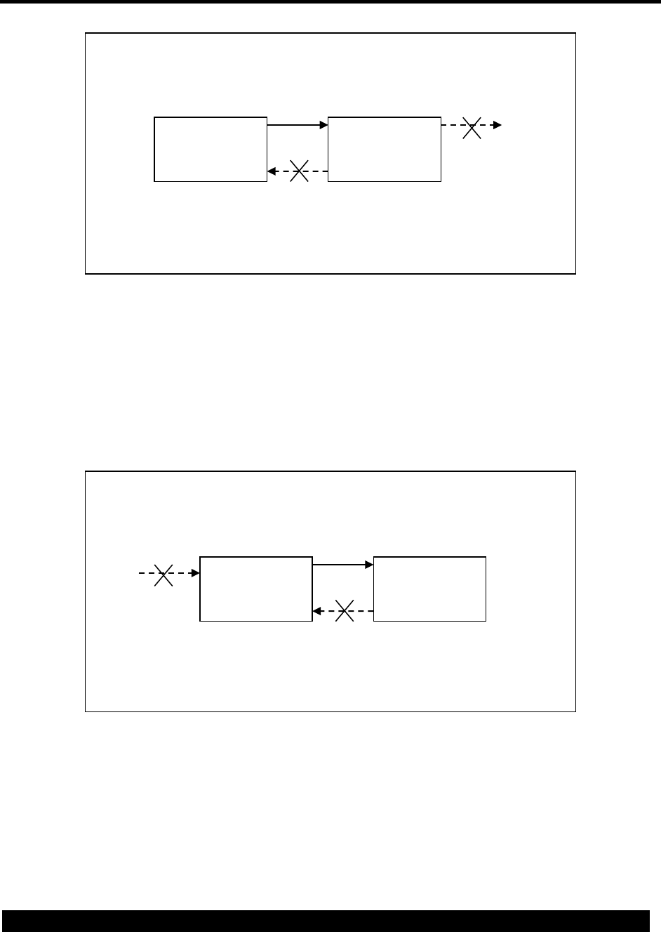
168
Tag-Write Endpoint Figure 5.
Tag-Read endpoints can only read data from a tag and then send data to downstream
endpoints. Tag-Read endpoints are source endpoints, which means they do not receive
information from an upstream endpoint and do not accept data from the downstream
endpoint. Tag-Read endpoints begin an endpoint chain.
Tag-Read Endpoint Figure 6.
Tag Endpoint Events 24.4.1
These events are generated by Tag Endpoints. The EventType is 117 for Tag Write
endpoints, and 122 for Tag Read endpoints. The ObjectId for the event is the tag id,
when available. See section 5 for more about events.
Name
EventType
EventId
Description
Tag-Read
Endpoint
Downstrea
mEndpoint
Upstream
Endpoint
Tag-Write
Endpoint

169
Tag Write Buf Empty
117
1
Tag Write endpoint buffer is empty.
Tag Write Error
117
2
Tag write error
Tag Read Start
122
1
Tag read started.
Tag Read Done
122
2
All tag data has been read.
AT$ENDPOINT 24.4.2
The AT command used to create a Tag endpoint is part of the general endpoint facility.
The syntax and parameters that are unique to Tag endpoints are shown in the following
sections. Endpoint settings can be set or read.
When a Tag endpoint is created it results in the Tag ID also being created in flash. If the
ID already exists then creating the tag endpoint will fail. Only one Tag endpoint can be
opened at a time. When the endpoint is deleted, this results in the Tag being closed. At
this point AT$TAGREAD may be used to read back the Tag.
Action'Command'
The following shows the command (in bold) to configure settings for a Tag Endpoint.
For Tag-Write:
AT$ENDPOINT=<endpointId>,<protocol=14>,<tagId>[,<bufferSize>[,<fwdTimeout>
[,<fwdDataSize>[,<fwdCtrlChar>]]]]
$ENDPOINT: ”<deviceId>”,<status>
(OK | ERROR)
For Tag-Read:
AT$ENDPOINT=<endpointId>,<protocol=15>,<tagId>[,<delete>[,<bufferSize>
[,<fwdTimeout>[,<fwdDataSize>[,<fwdCtrlChar>]]]]]
$ENDPOINT: ”<deviceId>”,<status>
(OK | ERROR)
For Deletion:
Specifying only the Endpoint ID deletes the endpoint.
AT$ENDPOINT=<endpointId>
$ENDPOINT: ”<deviceId>”,<status>
(OK | ERROR)
Read'Command'
The following shows the command (in bold) to query the Endpoint settings. All defined
records are displayed.
AT$ENDPOINT?

170
Output for a Tag-Write endpoint:
$ENDPOINT: ”<deviceId>”,<status>,<endpointId>,<protocol=14>,<tagId>,<bufferSize>,
<fwdTimeout>,<fwdDataSize>,<fwdCtrlChar>
…<more records>…
(OK | ERROR)
Output for a Tag-Read endpoint:
$ENDPOINT: ”<deviceId>”,<status>,<endpointId>,<protocol=15>,<tagId>,<delete>,
<bufferSize>, <fwdTimeout>,<fwdDataSize>,<fwdCtrlChar>
…<more records>…
(OK | ERROR)
Parameters
Command Parameter
Description
<endpoint Id>
The Id of the endpoint (1-49).
<protocol>
The type of endpoint being created:
14 = Tag-Write
15 = Tag-Read
(See section 15 for full protocol ID table)
<tagId>
The tag index that you wish to operate on (1-499).
<delete>
Tag-Read only. Delete tag after successful transfer:
0 = Do not delete (default).
1 = Delete tag.
<bufferSize>
Size of the data buffer (10 – 100000 bytes). Default=7250
<fwdTimeout>
Time to wait before forwarding data (10 – 3600000 msec).
Default=250msec
<fwdDataSize>
Number of bytes to buffer before forwarding data (10 –
100000). Default=1450
<fwdCtrlChar>
A control character to cause data to be forwarded. Enter a
decimal value (0 – 31). For example, ETX = 3. (256+ =
disabled). Default=disabled
<deviceId>
The Id of the modem.
<status>
The status of the command.
<status>
Description
0
Success
1012
Error saving data to NVM
1050
Invalid Parameter Value
1090
Invalid Endpoint Id
1093
Invalid Protocol
1100
Invalid Tag or tag does not exist
1101
Tag write in progress

171
1102
Tag is closed
1103
Tag memory error
24.5 Tag Commands
The following Tag commands are supported:
• AT$TAGFORMAT – command to format the tag file system.
• AT$TAGRECOMPACT – command to recompact the tag file system.
• AT$TAGINSTALL – command to install a firmware file.
• AT$TAGWRITE – command to create and write a new tag file.
• AT$TAGCLOSE – command to close a firmware file.
• AT$TAGDELETE – command to delete a tag file.
• AT$TAGREAD – command to read a tag file.
• AT$TAGSYSINFO – command to retrieve statistics for the tag file system.
• AT$TAGLISTALL – command to retrieve information on all defined tags.
• AT$TAGCREATE – command to create an empty tag file for later writing.
• AT$TAGDOWNLOADFTP – command to setup and query FTP tag downloads.
• AT$TAGDOWNLOADHTTP – command to setup and query HTTP tag
downloads.
• AT$TAGUPLOADFTP – command to setup and query FTP tag uploads.
• AT$TAGUPLOADHTTP – command to setup and query HTTP tag uploads.
24.6 Tag Format
These commands allow the user to format the Tag file system. This will result in all tag
files in the system being permanently deleted. The operation can take a long time.
During this time no other Tag operations may take place.
AT$TAGFORMAT 24.6.1
Command to reformat the tag file system.
Action'Command'
The following shows the command (in bold) to start the format process. While the format
is running, intermediate responses will be output indicating percentage completion.
AT$TAGFORMAT
$TAGFORMAT: ”<deviceId>”,<status>,<percentage>
(OK | ERROR)
Parameter
Description
<deviceId>
The ID of the modem.

172
<status>
The status of the command.
<percentage>
Percentage completion
<status>
Description
0
Success
1052
Format is already in progress.
1103
At least one tag still exists, or Recompact is in progress.
24.7 Tag Recompact
In some systems the Tag file system is implemented as a flat file system. In this case,
deleting Tags can leave “holes” in the flash memory map. These commands allow the
user to recompact the valid Tag files to free up FLASH memory for new files. The
operation can take a long time. During this time no other Tag operations may take
place. All tags must be closed before the recompact can start.
A recompact can be set up to be performed during initialization by setting the system
variable “tagrecompact” flag to 1. This allows the application to control when it is
performed. For example, it may be based on how much free or deleted tag memory
there is. Several system variables are provided for this support (see section 24.2):
• tagmemtotal – Total number of bytes in the tag memory
• tagmemdel – Number of deleted bytes
• tagmemfree – Number of free bytes
• tagrecompact – If this flag is set to 1, then a recompact will be performed during the
next restart. This will automatically close all open tags, recompact tag memory, then
clear the flag after the recompact completes.
For example, the application can define VARIABLETHRESHOLDs for the memory. The
threshold event can be used to trigger a VARIABLESET to set the recompact flag and
cause a system reset. This will cause the recompact during the restart.
AT$TAGRECOMPACT 24.7.1
Command to recompact the tag file system.
Action'Command'
The following shows the command (in bold) to start the format process. While the
recompact is running, intermediate responses will be output telling the user what
percentage of the operation is complete.
AT$TAGRECOMPACT
$TAGRECOMPACT: ”<deviceId>”,<status>,<percentage>

173
(OK | ERROR)
Parameter
Description
<deviceId>
The ID of the modem.
<status>
The status of the command.
<percentage>
Percentage complete with the recompact operation.
<status>
Description
0
Success
1052
Recompact is already in progress.
1103
Format is in progress, or a tag with unspecified size is
open. It must be closed to allow Recompact.
24.8 Tag Install
After a file has been written to the Tag file system, it may be used to install an update of
the cellular modem firmware or update the running software application. The install can
be started immediately, or triggered later by any event. Only one tag install can be
active at a time.
The Tag Install event labels are saved to NVM and restored after power cycles, unless
there are none specified. If the command is entered to be executed immediately, then
nothing is saved to NVM.
AT$TAGINSTALL 24.8.1
Command to install a firmware update file.
Action'Command'
The following shows the command (in bold) to start the install process.
AT$TAGINSTALL=<tagId>[,<installType>[,<eventLabel>[…,<eventLabel>]]]
$TAGINSTALL: ”<deviceId>”,<status>
(OK | ERROR)
To delete the Install event labels for a tag, enter the command with the Tag Id as the
only parameter:
AT$TAGINSTALL=<tagId>
To install a tag immediately, enter the command with the Tag Id and <eventLabel> = 0:

174
AT$TAGINSTALL=<tagId>,<installType>,0
Read'Command'
The following shows the command (in bold) to query the Tag Install settings.
AT$TAGINSTALL?
$TAGINSTALL:
”<deviceId>”,<status>,<tagId>,<installType>,<eventLabel>…,<eventLabel>
(OK | ERROR)
!!!Parameters!
Parameter
Description
<deviceId>
The ID of the modem.
<status>
The status of the command.
<tagId>
The ID of the tag to install (1-499).
<installType>
The type of file to install:
0 = Modem firmware or software (*.dwl). Default.
1 = PIC firmware over UART2 (*.img).
<eventLabel>
EventLabel in hex. This defines the event(s) that trigger
the install. There may be from 0 to 10 values. A 0 value
specifies “immediate”, and can appear by itself or
anywhere in the list.
Use the AT$EVENTLABEL command to aid with encoding
this parameter.
<status>
Description
0
Success
1052
Record is already defined, or in use.
1100
Invalid tag
1101
Tag write in progress
1103
Tag memory error
Examples'
The following example installs tag 1 immediately. Tag 1 contains a dwl file for a new
software version.
AT$TAGINSTALL=1,0,0

175
The next example configures tag 15 to be installed upon receiving the event for when
tag 15 has been closed. Tag 15 contains a dwl file for a new software version. The
<eventLabel> for Tag 15 Closed is 000C0F07 (see section 24.1).
Event Type = 12 for Tags
Object Id = 15 for Tag 15
Event Id = 7 for Tag Closed
The AT$EVENTLABEL command can be used to assist with encoding the correct hex
value:
AT$EVENTLABEL=12,15,7
$EVENTLABEL: "327004000672",0,"000c0f07"
OK
AT$TAGINSTALL=15,0,000c0f07
24.9 Tag Write
These commands convert the serial interface to data mode so the user can write data to
a Tag, using either raw or X-Modem. If the Tag does not exist, it is created first with an
unspecified size. If the Tag already exists and is still open, new data is appended. If
the tag is closed, it must first be deleted using AT$TAGDELETE. Writing is terminated
when X-Modem signals the end of file or when the serial port exits data mode with
“+++’.
Files that are transferred with X-Modem may have file pad characters of 0x1A appended
on the end. This is a result of the X-Modem protocol not supporting exact files sizes,
and always sending complete block sizes. This is normally not a problem with
executable or binary files because the characters will be ignored. But for text files, the
application may wish to strip the characters.
Note: If a tag file is created with an unspecified size, then no other tag files may be
open for writing at the same time. The file must be closed to allow other tag files to be
written. A power cycle automatically closes all tags.
AT$TAGWRITE 24.9.1
Command to create and write a new tag.
Action'Command'
The following shows the command (in bold) to write to a tag.
AT$TAGWRITE=<tagId>,<xmodem>

176
$TAGWRITE: ”<deviceId>”,<status>
(OK | ERROR)
Parameter
Description
<deviceId>
The ID of the modem.
<status>
The status of the command.
<tagId>
The ID of the tag to write(1-499).
<xmodem>
0: No X-Modem. Just send the file direct.
1: Use X-Modem or X-Modem 1K to transfer the file.
<status>
Description
0
Success
1100
Invalid Tag
1102
Tag is closed (read-only).
Example'
The following example creates tag 3 with data from the serial port.
AT$TAGWRITE=3,0
// To end the raw data transfer, enter:
+++
// Close the tag:
AT$TAGCLOSE=3,0
24.10 Tag Close
After data has been written to a Tag file, it may be closed so that no more writes are
allowed to it. The close can be done immediately, or triggered later by any event. A
power cycle automatically closes all tags.
The Tag Close event labels are saved to NVM and restored after power cycles, unless
there are none specified. If the command is entered to be executed immediately, then
nothing is saved to NVM.
AT$TAGCLOSE 24.10.1
Command to close a tag file.
Action'Command'
The following shows the command (in bold) to define the Tag Close settings.
AT$TAGCLOSE=<tagId>[,<eventLabel>[…,<eventLabel>]]

177
$TAGCLOSE: ”<deviceId>”,<status>
(OK | ERROR)
To delete the Close event labels for a tag, enter the command with the Tag Id as the
only parameter:
AT$TAGCLOSE=<tagId>
To close a tag immediately, enter the command with the Tag Id and <eventLabel> = 0:
AT$TAGCLOSE=<tagId>,0
Read'Command'
The following shows the command (in bold) to query the Tag Close settings.
AT$TAGCLOSE?
$TAGCLOSE: ”<deviceId>”,<status>,<tagId>,<eventLabel>…,<eventLabel>
(OK | ERROR)
!!!Parameters!
Parameter
Description
<deviceId>
The ID of the modem.
<status>
The status of the command.
<tagId>
The ID of the tag to close (1-499).
<eventLabel>
EventLabel in hex. This defines the event(s) that trigger
the install. There may be from 0 to 10 values. A 0 value
specifies “immediate”, and can appear by itself or
anywhere in the list.
Use the AT$EVENTLABEL command to aid with encoding
this parameter.
<status>
Description
0
Success
1052
Record is already defined, or in use.
1100
Invalid tag

178
Examples'
The following example closes tag 1 immediately.
AT$TAGCLOSE=1,0
The next example configures tag 15 to be installed upon receiving the event for when
tag 15 has completed being downloaded. The <eventLabel> for Tag 15 Download
Complete is 000C0F0B (see section 24.1).
Event Type = 12 for Tags
Object Id = 15 for Tag 15
Event Id = 11 for Download Complete
The AT$EVENTLABEL command can be used to assist with encoding the correct hex
value:
AT$EVENTLABEL=12,15,11
$EVENTLABEL: "327004000672",0,"000c0f0b"
OK
AT$TAGCLOSE=15,000c0f0b
24.11 Tag Delete
These commands delete a Tag file. The delete can be done immediately, or triggered
later by any event.
The Tag Delete event labels are saved to NVM and restored after power cycles, unless
there are none specified. If the command is entered to be executed immediately, then
nothing is saved to NVM.
AT$TAGDELETE 24.11.1
Command to delete a tag file.
Action'Command'
The following shows the command (in bold) to define the tag delete settings.
AT$TAGDELETE=<tagId>[,<eventLabel>[…,<eventLabel>]]
$TAGDELETE: ”<deviceId>”,<status>
(OK | ERROR)

179
To remove the Delete event labels for a tag, enter the command with the Tag Id as the
only parameter. Note that this does not delete the tag file:
AT$TAGDELETE=<tagId>
To delete a tag file immediately, enter the command with the Tag Id and <eventLabel> =
0:
AT$TAGDELETE=<tagId>,0
Read'Command'
The following shows the command (in bold) to query the Tag Delete settings.
AT$TAGDELETE?
$TAGDELETE: ”<deviceId>”,<status>,<tagId>,<eventLabel>…,<eventLabel>
(OK | ERROR)
!!!Parameters!
Parameter
Description
<deviceId>
The ID of the modem.
<status>
The status of the command.
<tagId>
The ID of the tag to delete (1-499).
<eventLabel>
EventLabel in hex. This defines the event(s) that trigger
the delete. There may be from 0 to 10 values. A 0 value
specifies “immediate”, and can appear by itself or
anywhere in the list.
Use the AT$EVENTLABEL command to aid with encoding
this parameter.
<status>
Description
0
Success
1052
Record is already defined, or in use.
1100
Invalid Tag
Examples'
The following example deletes tag 3 immediately.
AT$TAGDELETE=3,0

180
The next example configures tag 5 to be deleted upon receiving the event after tag 5
has been uploaded to a server. The <eventLabel> for Tag 5 Upload Complete is
000C050B (see section 24.1).
Event Type = 12 for Tags
Object Id = 5 for Tag 5
Event Id = 15 for Upload Complete
The AT$EVENTLABEL command can be used to assist with encoding the correct hex
value:
AT$EVENTLABEL=12,5,15
$EVENTLABEL: "327004000672",0,"000c050f"
OK
AT$TAGDELETE=5,000c050f
24.12 Tag Read
These commands are used to read a tag that has been created and written. There are
two modes for the Tag Read command. The partial read will just return the file status
such as file size. The full read will also dump the contents of the Tag to the serial port
through a data mode session.
AT$TAGREAD 24.12.1
Command to read a tag.
Action'Command'
AT$TAGREAD=<tagId>,<fullRead>
$TAGREAD:
”<deviceId>”,<status>,<tagId>,<tagSize>,<spaceUsed>,<spaceRemaining>,<finalized>
(OK | ERROR)
Parameter
Description
<deviceId>
The ID of the modem.
<status>
The status of the command.
<tagId>
The ID of the tag to read (1-499).
<fullRead>
0: Partial Read. Return Stats only.
1: Full Read. Dump full contents.
<tagSize>
The maximum allowed size of the tag. If tag is finalized,
this is the same as <spaceUsed>.

181
<spaceUsed>
The amount of space currently in use.
<spaceRemaining>
The amount of space remaining in the tag. 0 if the tag is
finalized.
<finalized>
Whether the tag is finalized or not.
<status>
Description
0
Success
1100
Invalid Tag
24.13 Tag System Information
These commands allow the user to receive all of the statistics for the Tag system as a
whole.
AT$TAGSYSINFO 24.13.1
Command to retrieve the Tag System statistics.
Action'Command'
AT$TAGSYSINFO
$TAGSYSINFO: ”<deviceId>”,<status>,<totalMemory>,<freeMemory>,<usedMemory>,
<deletedMemory>,<numberUsedTags>,<numberDeletedTags>
(OK | ERROR)
Parameter
Description
<deviceId>
The ID of the modem.
<status>
The status of the command.
<totalMemory>
The total amount of FLASH memory available for tags
<freeMemory>
The amount of FLASH memory available for creating new
tags.
<usedMemory>
The amount of FLASH memory used by valid tags
<deletedMemory>
The amount of FLASH memory taken up by deleted tags.
<numberUsedTags>
The number of valid tags currently stored.
<numberDeletedTags>
The number of tags that have been deleted.
<status>
Description
0
Success
1100
Invalid Tag

182
24.14 Tag List All
These commands return information on all the tags stored in the system. This amounts
to calling a partial Tag Read on all valid tags in the system.
AT$TAGLISTALL 24.14.1
Command to retrieve a summary of all tags.
Action'Command'
AT$TAGLISTALL
$TAGLISTALL:
”<deviceId>”,<status>,<tagId>,<tagSize>,<spaceUsed>,<spaceRemaining>, <finalized>
$TAGLISTALL:
”<deviceId>”,<status>,<tagId>,<tagSize>,<spaceUsed>,<spaceRemaining>, <finalized>
…
(OK | ERROR)
Parameter
Description
<deviceId>
The ID of the modem.
<status>
The status of the command.
<tagId>
The ID of the tag to read.
<tagSize>
The maximum allowed size of the tag. If tag is finalized,
this is the same as <spaceUsed>.
<spaceUsed>
The amount of space currently in use.
<finalized>
Whether the tag is finalized or not.
<status>
Description
0
Success
1100
Invalid Tag
24.15 Tag Create
These commands create an empty tag file of a specified size for later writing. The
creation can be done immediately, or triggered later by any event. A maximum file size
can be specified so that multiple tag files may be open for writing at the same time. The
size can also be unspecified, in which case only one tag file may be open for writing at a
time. A file of unspecified size must be closed to allow other tag files to be written. A
power cycle automatically closes all tags.

183
The Tag Create event labels are saved to NVM and restored after power cycles, unless
there are none specified. If the command is entered to be executed immediately, then
nothing is saved to NVM.
AT$TAGCREATE 24.15.1
Command to create an empty tag file of a specified size for later writing.
Action'Command'
The following shows the command (in bold) to define the Tag Create settings.
AT$TAGCREATE=<tagId>[,<fileSize>[,<eventLabel>[…,<eventLabel>]]]
$TAGCREATE: ”<deviceId>”,<status>
(OK | ERROR)
To remove the Tag Create settings for a tag, enter the command with the Tag Id as the
only parameter. Note that this does not delete the tag file if it has already been created:
AT$TAGCREATE=<tagId>
To create a tag file immediately, enter the command with the <eventLabel> = 0:
AT$TAGCREATE=<tagId>,<fileSize>,0
Read'Command'
The following shows the command (in bold) to query the Tag Create settings.
AT$TAGCREATE?
$TAGCREATE: ”<deviceId>”,<status>,<tagId>,<fileSize>,<eventLabel>…,<eventLabel>
(OK | ERROR)
!!!Parameters!
Parameter
Description
<deviceId>
The ID of the modem.
<status>
The status of the command.
<tagId>
The ID of the tag to create (1-499).
<fileSize>
Maximum file size.
If null or 0, then no other tag files may be written until this

184
one is closed.
<eventLabel>
EventLabel in hex. This defines the event(s) that trigger
the create. There may be from 0 to 10 values. A 0 value
specifies “immediate”, and can appear by itself or
anywhere in the list.
Use the AT$EVENTLABEL command to aid with encoding
this parameter.
<status>
Description
0
Success
1052
Record is already defined, or in use.
1100
Invalid Tag
1103
Tag memory error
Examples'
The following example creates tag 3 immediately.
AT$TAGCREATE=3,0
The next example configures tag 5 to be created upon receiving the event after tag 5
has been deleted, such as after an upload. The <eventLabel> for Tag 5 deleted is
000C0508 (see section 24.1).
Event Type = 12 for Tags
Object Id = 5 for Tag 5
Event Id = 8 for Tag Deleted
The AT$EVENTLABEL command can be used to assist with encoding the correct hex
value:
AT$EVENTLABEL=12,5,8
$EVENTLABEL: "327004000672",0,"000c0508"
OK
AT$TAGCREATE=5,000c0508
24.16 Tag Download
These commands initiate the download of data from an FTP or HTTP server to a newly
created tag file. The download can be started immediately, or triggered by any event.
Other optional parameters allow the file to be unzipped before writing to the tag file.

185
The Tag Download parameters are saved to NVM and restored after power cycles,
unless there are no events specified. If the command is entered to be executed
immediately, then nothing is saved to NVM.
AT$TAGDOWNLOADFTP and 24.16.1
AT$TAGDOWNLOADHTTP
These commands initiate a download of data from an FTP or HTTP server to a newly
created tag file. Both commands are identical, except for the type of server that is
connected:
• AT$TAGDOWNLOADFTP – Connects to an FTP server.
• AT$TAGDOWNLOADHTTP – Connects to an HTTP server.
In the following sections, the command is shown as AT$TAGDOWNLOADxxx, where
the “xxx” can be either “FTP” or “HTTP”.
Action'Command'
The following shows the commands (in bold) to initiate a Tag Download session.
AT$TAGDOWNLOADxxx=<tagDownloadId>,<eServerId>,”<filename>”,<tagId>
[,<decompress>[,<eventLabel>[…,<eventLabel>]]]
$TAGDOWNLOADxxx: ”<deviceId>”,<status>
OK | ERROR
The above command response indicates the status of the command and its parameters.
If successful, then when triggered by an <eventLabel>, a connection will be established
with the server, and the file transfer will begin. Unsolicited messages will be output to
indicate the progress:
$TAGDOWNLOADxxx: ”<deviceId>”,<status>,<tagDownloadId>,<downloadStatus>
[,<detail>]
To delete a Tag Download Id, enter the command with the Tag Download Id as the only
parameter:
AT$TAGDOWNLOADxxx=<tagDownloadId>
To abort an active download session, enter the command with <eServerId> = 0:
AT$TAGDOWNLOADxxx=<tagDownloadId>,0

186
Read'Command'
The following shows the command (in bold) to query the Tag Download settings.
AT$TAGDOWNLOADxxx?
$TAGDOWNLOADxxx:
”<deviceId>”,<status>,<tagDownloadId>,<eServerId>,”<filename>”,
<tagId>,<decompress>,<eventLabel>…,<eventLabel>
(OK | ERROR)
Parameter
Description
<deviceId>
The ID of the modem.
<status>
The status of the command.
<tagDownloadId>
Tag Download identifier (1-20).
<eServerId>
Endpoint Server Id. The Eserver contains the server’s IP
address, and optional port, username, and password.
If <eServerId> = 0, it is a special case used to abort an
download process already in progress.
<filename>
File path and name.
<tagId>
Tag file to be downloaded.
<decompress>
Not currently supported.
Type of decompression performed on the tag file before
writing to the tag file:
0 = None (default)
1 = zlib
2 = bzip
<eventLabel>
EventLabel in hex. This defines the event(s) that trigger
the starting of the download. There may be from 0 to 10
values. A null or 0 value specifies “immediate” (default).
Use the AT$EVENTLABEL command to aid with encoding
this parameter.
<downloadStatus>
Status of the download process:
1 = Connected to server and transfer is starting.
2 = Done. Tag file written.
3 = Login error.
4 = File not found.
5 = Server connection error.
6 = Startup error.
7 = Transfer aborted.
<detail>
Extra detail for <downloadStatus>:
If <downloadStatus> = 1, 2, or 6 then <detail> = Tag Id.

187
<status>
Description
0
Success
1017
Invalid Filename
1052
Download session is active
1055
Invalid EServer Id
1100
Invalid Tag Id
1101
Tag write in progress
1102
Tag is closed
1103
Tag memory error
Examples'
The following example creates TagDownload 1 that reads a file from the FTP server
referenced by EServer 5 and writes it to Tag 3. Since no <eventLabel> is specified, the
transfer begins immediately.
AT$ESERVER=5,ftp.example.com,,”myid”,”mypwd”
AT$TAGDOWNLOADFTP=1,5,"destfile.dat",3
The next example is the same as above, except that it does not begin the transfer until
timer 1 expires. The <eventLabel> for Timer 1 expiration is 00020103 (see section
10.5.1).
Event Type = 2 for Timers
Object Id = 1 for Timer 1
Event Id = 3 for Timer Expiration
The AT$EVENTLABEL command can be used to assist with encoding the correct hex
value:
AT$EVENTLABEL=2,1,3
$EVENTLABEL: "327004000672",0,"00020103"
OK
AT$TAGDOWNLOADFTP=1,5,"destfile.dat",3,0,00020103
This command creates Timer 1 with a duration of 30 seconds:
AT$TIMERSTART=1,300

188
Firmware Upgrade (FOTA) 24.16.2
A special case for using the Tag Download and Install commands is to upgrade the
device firmware over the air (FOTA). The AT Tag Download command can be used to
setup the download session to be performed immediately or later when a system event
occurs. The firmware file will be downloaded from the server and stored in a tag file.
Then, to have the new firmware activated, the AT Tag Install command is used to load
the tag file into execution memory and restart the device.
The device uses unsolicited REPORT messages to provide the status of the firmware
upgrade process. Once the device starts the upgrade, it sends a REPORT message
with an event indicating “FOTA download started”. After the upgrade is complete and
the device has rebooted, it will send a REPORT message with an event indicating
“FOTA upgrade complete”. See section 11.7 for details of the REPORT message.
Example'
The following example creates TagDownload 1 that reads a firmware file from the FTP
server referenced by EServer 5 and writes it to Tag 3. Since no <eventLabel> is
specified, the transfer begins immediately.
AT$ESERVER=5,ftp.example.com,,”myid”,”mypwd”
AT$TAGDOWNLOADFTP=1,5,"newfirmware.dwl",3
After the download has completed, the new firmware file is installed and activated by the
following command:
AT$TAGINSTALL=3,0,0
24.17 Tag Upload
These commands initiate the upload of data from a tag file to an FTP or HTTP server, or
to a remote server using the binary protocol. The upload can be started immediately, or
triggered by any event. Other optional parameters allow the file to be compressed
before sending to the server, and to delete the tag after successful upload. The tag file
must be closed before uploading it.
The uploads are performed on a remote server that is configured with the EServer
commands. Currently, for FTP only, a server connection must be opened with
AT$FTPOPEN before the upload can start. When finished, other FTP operations (such
as AT$FTPREN) may be performed, or the connection can be closed.
The Tag Upload parameters are saved to NVM and restored after power cycles, unless
there are no events specified. If the command is entered to be executed immediately,
then nothing is saved to NVM.

189
AT$TAGUPLOADFTP and AT$TAGUPLOADHTTP 24.17.1
These AT commands initiate the upload of data from an existing tag file to an FTP or
HTTP server. Both commands are identical, except for the type of server that is
connected:
• AT$TAGUPLOADFTP – Connects to an FTP server.
• AT$TAGUPLOADHTTP – Connects to an HTTP server.
In the following sections, the command is shown as AT$TAGUPLOADxxx, where the
“xxx” can be either “FTP” or “HTTP”.
Action'Command'
The following shows the commands (in bold) to initiate a Tag Upload session.
AT$TAGUPLOADxxx=<tagUploadId>,<eServerId>,”<filename>”,<tagId>[,<compre
ss> [,<delete>[,<eventLabel>[…,<eventLabel>]]]]
$TAGUPLOADxxx: ”<deviceId>”,<status>
OK | ERROR
The above command response indicates the status of the command and its parameters.
If successful, then when triggered by an <eventLabel>, a connection will be established
with the server, and the file transfer will begin. Unsolicited messages will be output to
indicate the progress:
$TAGUPLOADxxx: ”<deviceId>”,<status>,<tagUploadId>,<uploadStatus>[,<detail>]
To delete a Tag Upload Id, enter the command with the Tag Upload Id as the only
parameter:
AT$TAGUPLOADxxx=<tagUploadId>
To abort an active upload session, enter the command with <eServerId> = 0:
AT$TAGUPLOADxxx=<tagUploadId>,0
Read'Command'
The following shows the command (in bold) to query the Tag Upload settings.
AT$TAGUPLOADxxx?

190
$TAGUPLOADxxx:
”<deviceId>”,<status>,<tagUploadId>,<eServerId>,”<filename>”,<tagId>,
<compress>,<delete>,<eventLabel>…,<eventLabel>
(OK | ERROR)
Parameter
Description
<deviceId>
The ID of the modem.
<status>
The status of the command.
<tagUploadId>
Tag Upload identifier (1-20).
<eServerId>
Endpoint Server Id. The Eserver contains the server’s IP
address, and optional port, username, and password.
If <eServerId> = 0, it is a special case used to abort an
upload process already in progress.
<filename>
File path and name.
<tagId>
Tag file to be uploaded.
<compress>
Not currently supported.
Type of compression performed on the tag file before
uploading to the server:
0 = None (default)
1 = zlib
2 = bzip
<delete>
Delete the tag after successful transfer:
0 = Do not delete (default).
1 = Delete tag.
<eventLabel>
EventLabel in hex. This defines the event(s) that trigger
the starting of the upload. There may be from 0 to 10
values. A null or 0 value specifies “immediate” (default).
Use the AT$EVENTLABEL command to aid with encoding
this parameter.
<uploadStatus>
Status of the upload process:
1 = Connected to server and transfer is starting.
2 = Done. Tag file written to server.
3 = Login error.
4 = File not found.
5 = Server connection error.
6 = Startup error.
7 = Transfer aborted.
<detail>
Extra detail for <uploadStatus>:
If <uploadStatus> = 1, 2, or 6 then <detail> = Tag Id.
<status>
Description

191
0
Success
1017
Invalid Filename
1052
Upload session is active
1055
Invalid EServer Id
1100
Invalid Tag Id
1101
Tag is still open for writing. Must be closed before upload.
1103
Tag memory error
Examples'
The following example creates TagUpload 1 that reads data from Tag 3 and sends it to
an FTP server referenced by EServer 5. Since no <eventLabel> is specified, the transfer
begins immediately.
AT$ESERVER=5,ftp.example.com,,”myid”,”mypwd”
AT$FTPOPEN=5,0
AT$TAGUPLOADFTP=1,5,"destfile.dat",3
The next example is the same as above, except that it does not begin the transfer until
timer 1 expires. The <eventLabel> for Timer 1 expiration is 00020103 (see section
10.5.1).
Event Type = 2 for Timers
Object Id = 1 for Timer 1
Event Id = 3 for Timer Expiration
The AT$EVENTLABEL command can be used to assist with encoding the correct hex
value:
AT$EVENTLABEL=2,1,3
$EVENTLABEL: "327004000672",0,"00020103"
OK
AT$TAGUPLOADFTP=1,5,"destfile.dat",3,0,0,00020103
This command creates Timer 1 with a duration of 30 seconds:
AT$TIMERSTART=1,300
25 GPIO
These commands are used to manipulate GPIOs.

192
• AT$GPIOCONFIG
• AT$GPIOREAD
• AT$GPIOWRITE
• AT$GPIOACTION
• AT$GPIOACTIONMULTI
25.1 Events
The GPIO subsystem generates events that may be used to trigger actions in other
subsystems. These are the GPIO events available:
Event ID
Event Name
Description
1
Input Low
This Event is triggered when a GPIO input
changes from High to Low.
2
Input High
This Event is triggered when a GPIO input
changes from Low to High.
3
Output Low
This event is triggered when a GPIO output is
changed to low
4
Output Hi
This event is triggered when a GPIO output is
changed to high
25.2 String Tokens
This subsystem defines the following dynamic string tokens:
Name
Description
Prefix #
Postfix #
gpio
Status of GPIO pin
–
pin
25.3 AT$GPIOCONFIG
The $GPIOCONFIG command allocates and configures system GPIOs. It has five
modes, mode 0 deallocates a GPIO, mode 1 allocates and configures a GPIO, modes 2
and 3 show status and capabilities, and modes 4 and 5 save and delete the current
GPIO configuration to and from flash.
Action Command 25.3.1
Mode = 0: Deallocate the GPIO
AT$GPIOCONFIG=<mode>[,<gpiold>]

193
(OK | ERROR)
Mode=1: Allocate and set the GPIO configuration
AT$GPIOCONFIG=<mode>,<gpiold>,<gpioDir>[,<gpioVal>]
(OK | ERROR)
Mode=2: List the current GPIO status for all GPIO (allocated or not)
AT$GPIOCONFIG=<mode>
$GPIOCONFIG: “<deviceId>”,<status>,<gpiold>,<gpioStatus>
[$GPIOCONFIG: <gpiold>,<gpioStatus>[…]]
(OK | ERROR)
Mode=3: List the GPIO capabilities for all GPIO (allocated or not)
AT$GPIOCONFIG=<mode>
$GPIOCONFIG: “<deviceId>”,<status>,<gpiold>,<gpioAccess>
[$GPIOCONFIG: <gpiold>,<gpioAccess>[…]]
(OK | ERROR)
Mode=4: Save the current GPIO configurations to NVM
Mode=5: Delete the current GPIO configuration from NVM
AT$GPIOCONFIG=<mode>
(OK | ERROR)
Read Command 25.3.2
AT$GPIOCONFIG?
$GPIOCONFIG: “<deviceId>”,<status>,<gpiold>,<gpioVal>
(OK | ERROR)
!!!Parameters!
Parameter
Description
<mode>
0 = Delete GPIO configuration
1 = Configure GPIO
2 = List current status for all GPIOs (allocated or not)
3 = List the GPIO capabilities for all GPIO (allocated or
not)
4 = Save the current gpio configurations to NVM
5 = Delete the current gpio configuration from NVM
<gpioId>
GPIO name. See product specification for supported
GPIOs.
<status>
The status of the command.
<gpioDir>
0 = Input

194
1 = Output
<gpioVal>
0 = Low
1 = High
<gpioStatus>
0 = Input
1 = Output
3 = Not available
4 = Available
<gpioAccess>
Bit 1 Output is readable
Bit 2 Input is writable
<deviceId>
The ID of the modem.
<status>
Description
0
Success
25.4 AT$GPIOREAD
The $GPIOREAD command is used to read the level of one or more allocated GPIOs.
Action Command 25.4.1
AT$GPIOREAD=<gpioId>[,...<gpioIdN>]
$GPIOREAD:“<deviceId>”,<status>,<gpiold>,<gpioVal>
[$GPIOREAD:“<deviceId>”,<status>,<gpiold>,<gpioVal>]
(OK | ERROR)
Read Command 25.4.2
None
See AT$GPIOCONFIG for definition of parameters.
25.5 AT$GPIOWRITE
The $GPIOWRITE command is used to set the value for one or more allocated GPIO
outputs.
Action Command 25.5.1
AT$GPIOWRITE=<level>,<gpioId>[,...<gpioIdN>]
$GPIOWRITE:“<deviceId>”,<status>,<Gpiold>,<level>

195
[$GPIOWRITE:“<deviceId>”,<status>,<Gpiold>,<level>]
(OK | ERROR)
Read Command 25.5.2
None
See AT$GPIOCONFIG for definition of parameters
25.6 AT$GPIOACTION
This command allows you to define the read or write actions on a single GPIO based on
one or more events. If no events are defined the action is taken immediately. This
command requires that the GPIOs first be configured by the $GPIOCONFIG or
SETGPIOCONFIG command.
AT$GPIOACTION=<ID>[,<action>,<gpioID1>,<eventLabel1>,[,...<eventLabelN>]
$GPIOACTION: “<deviceId>”,<status>,<gpioActionId>,<action>,
<gpioId>,<eventLabel1>[,...<eventLabelN>]]
(OK | ERROR)
Parameter
Description
<ID>
User designated value for this GPIO action
<action>
Operation to be performed by GPIO:
0 - Write output level LOW
1 - Write output level HIGH
2 - Toggle output level
3 - READ
<eventLabel>
Event to trigger the GPIO action.
See AT$GPIOCONFIG for more definition of parameters.
25.7 AT$GPIOACTIONMULTI
This command allows you to define the read or write actions on multiple GPIOs based
on one event. This command requires that the GPIOs first be configured by the
$GPIOCONFIG or SETGPIOCONFIG command.
Command:
AT$GPIOACTIONMULTI=<ID>,<action>,<eventLabel>,<gpioId1>[,...<gpioId
N>]
Response:
AT$GPIOACTIONMULTI=“<deviceId>”,<status>,<gpioActionId>,<action>,<ev
entLabel>,<gpioId1>[,...<gpioIdN>]]
(OK | ERROR)

196
Unsolicited
response
(read
action)!
$GPIORDEVT:“<deviceId>”,<status>,<ID>,<gpioId>,<gpioVal>
See AT$GPIOACTION and AT$GPIOCONFIG for definition of parameters.
25.8 Examples
This example defines GPIO 29 to go high when an incoming call event is detected. It
also reads the GPIO and stores the configuration.
AT$GPIOCONFIG=1,29,1,0 //Configure GPIO29 as an output with
OK //value 0
AT$GPIOACTION=1,1,29,00070004 //Configure GPIO29 to go high when an
//incoming call is detected
$GPIOACTION: "327004006981",0,1,1,29,"00070004"
OK
AT$GPIOREAD=29 //Read GPIO 29
$GPIOREAD: "327004006981",0,"GPIO29",0
OK
AT$GPIOCONFIG=4 //Save the current GPIO configuration
OK

197
26 Voice Call System
26.1 Overview
The Voice Call system provides commands to originate, answer, and hang up voice
calls. It also offers a subscription to unsolicited voice call events, such as incoming
calls.
The software event system used together with the Voice Call commands, enables a
user to configure simple or complex scenarios such as:
• Make a voice call when a specified sequence of GPIO state changes have
occurred
• Answer a call if the call comes from a list of specified phone numbers
To use the Voice Call commands, the Voice Call system must first be enabled with the
command AT$VOICECALL. This command also enables and disables unsolicited Voice
Call event responses.
This is a list of the Voice call system’s AT commands:
• AT$VOICECALL
• AT$CALLSTART
• AT$CALLANSWER
• AT$CALLHANGUP
26.2 Event Ids
Below is a list of all the events that are generated by the Voice Call system.
Event Id
Event Name
1
Call dialing (originated OK)
2
Call origination failed
3
Call alerting (ringing at the other end)
4
Incoming call
5
Call ended (any reason)
6
Call is in active state
7
Audio path opened

198
26.3 AT$VOICECALL
This command has two purposes; Enables or disable the Voice call system which
activates the Voice Call commands, and enables or disables unsolicited Voice Call
events and responses.
This command has two purposes; Enable or disable the Voice call system which
activates the Voice Call commands, and enable or disable unsolicited Voice Call events
and responses.
After the Voice call system is activated, it is not recommended to use the “standard”
voice call commands, such as ATD, ATA, etc.
Action Command/Response 26.3.1
Sets the current settings.
Command:
AT$VOICECALL=<mode>[,<monitor>]
Response:
$ VOICECALL: “<deviceId>”,<status>
OK
Read Command/Response 26.3.2
Returns the current settings.
Test Command/Response 26.3.3
Returns the allowed parameters
Command:
AT$VOICECALL=?
Response:
$ VOICECALL: “<deviceId>”, (0-1),(0-1) .
OK
Unsolicited response 26.3.4
When <monitor> is enabled, the following unsolicited response will be sent when a
Voice Call event occurs:
$VOICECALLIND: “<deviceId>”,<status>,<event>
Command:
AT$VOICECALL?
Response:
$ VOICECALL: “<deviceId>”, <mode>,<monitor> .
OK

199
!!!Parameters!!
Parameter
Value
Description
<mode>
0
Disable Voice Call system
1
Enable Voice Call system
<monitor>
0
Disable Voice Call unsolicited responses
1
Enable Voice Call unsolicited responses
<event>
1-7
Voice Call event Id. See table in chapter 26.2
<deviceId>
string
The ID of the modem
<status>
0 = Success
1 = Failed to start the Voice call system
1012 = Failed to save configuration to
memory
1050 = Invalid parameter value
26.4 AT$CALLSTART
This command is a request to originate a call. The <objectId> is used for identifying the
call.
It is possible to associate with an <eventLabel> (see AT$EVENTLABEL) to allow the
command to be executed only if a certain event occurs. If the <eventLabel> is omitted,
the command will execute immediately.
To delete the association, issue the command with <objectId> as the only parameter.
Action Command/Response 26.4.1
Command:
AT$CALLSTART=<objectId>,<phonenumber>[,<eventLabel>[,<eve
ntLabel> ..]]
Response:
$CALLSTART: “<deviceId>”,<status>
OK
Read Command/Response 26.4.2
If one or more <eventLabels> are associated with the command, the Read command
will display these commands.
Command:
AT$CALLSTART?
Response:
$ CALLSTART:
“<deviceId>”,<status>,<objectId>[,<phonenumber>[,<eventLabel>[,<eventLabel>]]]]

200
“<deviceId>”,<status>,<objectId>[,<phonenumber>[,<eventLabel>[,<eventLabel>]]]]
..
OK
26.4.3
!!!Parameters!!!!!!!!
Parameter
Value
Description
<objectId>
1-255
Identification for the Call Start instance
<phonenumber>
0-9, *, #
String with max 20 digits
<eventLabel>
00000000 -
FFFFFFFF
See AT$EVENTLABEL for more details.
Several <eventLabel>s can be associated
with a command.
“<deviceId>”
String
<status>
0 = Success
1012 = Failed to save configuration to
memory
1050 = Invalid parameter value
1052 = Could not store request
1066 = Error occurred while handling the
event
26.5 AT$CALLANSWER
This command can be used to answer an incoming call with or without checking and
matching the phone number. If a <phonenumber> is specified, the call will be answered
only if the <phonenumber> matches the incoming phone number. To immediately
answer the call, an <objectId> of 0 can be used, or the <objectId> can be omitted.
The command can be associated with one or several <eventLabel>s which allows a
user to configure events that have to happen in order for the command to be executed.
A non-zero <objectId> is required. For example:
• Answer when there is an incoming voice call with a specific phone number
• Answer when there is an incoming call and a specified GPIO is set to High
If it is desired to have more than one phone number, several instances of this command
can be configured. Just use different <objectId>s. If all voice calls are to be answered,
omitting the <phonenumber> parameter will answer any call.
The <objectId> is used to identify this configuration. To delete the configuration, issue
the command with just the <objectId> as parameter.

201
Wildcards (*, #) are allowed in the <phonenumber> parameter. The * means any
numbers of digits, and # means one digit. Examples:
919123* means any phone number starting with 919123.
919123#567 means 9191231567, 9191232567, or 9191233567 ..etc.
Action Command/Response 26.5.1
Answer an incoming call, or configure the device to answer a call at a later time using
the <eventLabel> parameter.
Command:
AT$CALLANSWER[=<objectId>[,<phonenumber>[,<eventLabel>[,<
eventLabel> ..]]]]
Response:
$CALLANSWER: “<deviceId>”,<status>
OK
Read Command/Response 26.5.2
If one or more <eventLabels> are associated with the command, the Read command
will display these commands.
Comman
d:
AT$CALLANSWER?
Response
:
$ CALLANSWER:
“<deviceId>”,<status>,<objectId>,<phonenumber>,<eventLabel>[,<event
Label> ..]
OK
26.5.3
!!!Parameters!!!!!!!!
Parameter
Value
Description
<objectId>
0-255
Call answer configuration identifier
<phonenumber>
0-9, *, #
String with max 20 digits
<eventLabel>
00000000 -
FFFFFFFF
See AT$EVENTLABEL for more details.
Several <eventLabel>s can be associated
with a command.
“<deviceId>”
String
<status>
0 = Success
1 = Failed to answer the call
1012 = Failed to save configuration to
memory
1050 = Invalid parameter value

202
1052 = Could not store request
1066 = Error occurred while handling the
event
26.6 AT$CALLHANGUP
This command ends a call. If the command is issued when there is an active call in
progress, the call in progress will be ended.
It is possible to associate this command with an eventLabel (see AT$EVENTLABEL) to
allow the command to be executed only if a certain event occurs. If the <eventLabel> is
omitted or if <objectId>=0 or omitted, the command will execute immediately.
If the command is used with an <eventlabel>, scenarios like the following can be
configured:
• Hang-up any call in progress when GPIO 5 goes high
• Hang-up any incoming calls
The <objectId> is used for identifying an instance of a saved AT$CALLHANGUP
configuration. To delete a configuration, issue the command with <objectId> as the only
parameter.
Action Command/Response 26.6.1
Command:
AT$CALLHANGUP[=<objectId>[,<eventLabel>[,<eventLabel> ..]]]
Response:
$CALLHANGUP: “<deviceId>”,<status>
OK
Read Command/Response 26.6.2
If one or more <eventLabel>s are associated with the command, the Read command
will display these commands.
Command:
AT$CALLHANGUP?
Response:
$ CALLHANGUP: “<deviceId>”,
<objectId>,<eventLabel>[,<eventLabel>]]] .
OK
26.6.3
!!!Parameters!

203
Parameter
Value
Description
<objectId>
0-255
Call answer configuration identifier
<eventLabel>
00000000 -
FFFFFFFF
See AT$EVENTLABEL for more details.
Several <eventLabel>s can be associated
with a command.
“<deviceId>”
String
<status>
0 = Success
1 = Failed to answer the call
1012 = Failed to save configuration to
memory
1050 = Invalid parameter value
1052 = Could not store request
1066 = Error occurred while handling the
event
26.7 Voice Call Examples
This example illustrates how to originate a voice call immediately, and also how to
configure the device to answer any incoming calls automatically.
In these examples, the device id is 327004006981.
AT$VOICECALL=1,1 //Enable Voice Call system
$VOICECALL: "327004006981",0
OK
AT$CALLSTART=0,”1234567” //Originate call
$CALLSTART: "327004006981",0
OK
$VOICECALLIND: "327004006981",0,7,0 //Audio path opened
$VOICECALLIND: "327004006981",0,3,0 //Alerting
$VOICECALLIND: "327004006981",0,1,0 //Voice originated successfully
AT$CALLHANGUP //Hang up call
$CALLHANGUP: "327004006981",0
OK
AT$CALLANSWER=1,1,00070004 //Configure device to answer any
$CALLANSWER: "327004006981",0 //incoming call
OK
$VOICECALLIND: "327004006981",0,4,0 //Incoming call event
RING //RING indication
$VOICECALLIND: "327004006981",0,7,0 //Audio path opened
$VOICECALLIND: "327004006981",0,6,0 //Call is in active state
AT$CALLHANGUP //Hang up call
$CALLHANGUP: "327004006981",0

204
OK
$VOICECALLIND: "327004006981",0,5,0 //Call ended

205
27 DTMF Tone System
27.1 Overview
The DTMF system provides the ability to play and detect DTMF tones on the
speaker/microphone or over the network during an active voice call.
The DTMF commands can be executed immediately, or they can be combined with the
Event system. The Event system allows a user to configure the commands to be
executed when one or more events occurs. For example:
• Play a DTMF tone when a voice call is active and a specified GPIO goes high
• Cause an action when a specific DTMF tone has been detected
The following commands are supported:
• AT$DTMFPLAY – Action and Read commands
• AT$DTMFDETECT – Action and Read commands
27.2 DTMF Event Ids
The DTMF system will generate the events in the table below.
Note! When a tone starts playing, there will be a DTMF Play Start event generated, but
there will not be a DTMF Play Tone Stop event, unless the user explicitly issues the
DTMF Detect command with mode set to Stop.
Event Id
Event Name
0
DTMF tone ‘0’ detected
1
DTMF tone ‘1’ detected
2
DTMF tone ‘2’ detected
3
DTMF tone ‘3’ detected
4
DTMF tone ‘4’ detected
5
DTMF tone ‘5’ detected
6
DTMF tone ‘6’ detected
7
DTMF tone ‘7’ detected
8
DTMF tone ‘8’ detected
9
DTMF tone ‘9’ detected
10
DTMF tone ‘A’ detected
11
DTMF tone ‘B’ detected
12
DTMF tone ‘C’ detected
13
DTMF tone ‘D’ detected
16
DTMF tone ‘*’ detected

206
17
DTMF tone ‘#’ detected
20
DTMF play tone stop
21
DTMF play tone start
23
DTMF Detection mode disabled
24
DTMF Detection mode enabled
27.3 AT$DTMFPLAY
This command will play a DTMF tone on the speaker or send the tone over the network
The DTMF Play tone event will be generated when the mode parameter is set to start
playing, and a DTMF Play Stop event will be generated if the command is issued with
mode set to Stop playing. There will not be an unsolicited DTMF Stop Play event
generated when the tone has finished playing.
Action Command/Response 27.3.1
Command:
AT$DTMFPLAY=<objectId>[,<mode>,<path>,[,<tone>[,<gain>[,<dur
ation>[,<eventLabel>[,<eventLabel>]]]]]]]
Response:
$DTMFPLAY: “<deviceId>”,<status>
OK
If the eventLabel is omitted, and <objectId> is set to 0, the command will be executed
immediately.
If one or more <eventLabel>s are provided and <objectId> is not 0, the command will
execute when one of the events, specified in the <eventLabel>, has occurred. The
command will remain associated with the event, and execute the next time any of the
events occur.
To delete an association, issue the command with just the <objectId>,
AT$DTMFPLAY=<objectId>
Read Command/Response 27.3.2
The read command will display all DTMFPLAY requests that are associated with an
eventLabel.
Command:
AT$DTMFPLAY?
Response:
$DTMFPLAY:
“<deviceId>”,<status>,<objectId>,<mode>,<path>,<tone>,<gain>,<durat
ion>,<eventLabel>
[,<eventLabel> …]

207
….
OK
!!!Parameters!!!!!!!!
Parameter
Value
Description
<objectId>
0-20
0 = Execute command immediately
1 - 20 = Associate the command with an
<eventLabel>
<mode>
0,1
0 = Stop playing tone
1 = Start playing tone
<path>
0,1
Output path
0 = Speaker
1 = Sent over the network. This option is only
valid if a voice call is active.
<tone>
0-9, *,#,A,B,C,D
DTMF tones
<duration>
1-65353
Number of 20 ms units
<gain>
Tone gain (dB) for the speaker.
<eventLabel>
See AT$EVENTLABEL for more details.
<devideId>
String
The ID of the modem
<status>
0 = Success
1012 = Failed saving to permanent memory
1050 = Invalid parameter value
1066 = The <eventLabel> format incorrect
1071 = Failed to initialize the Audio system
1072 = Failed to Play tone
27.4 AT$DTMFDETECT
This command will put the device into DTMF listening mode.
If the <tone> parameter is included, the device will only be listening for that <tone>. If all
tones are to be detected, specify X as the tone parameter. All tones are also the default
value, if this parameter is omitted.
If the <eventLabel> is omitted, and <objectId> is set to 0, the command will be executed
immediately.
If one or more <eventLabel>s are provided and <objectId> is not 0, the command will
execute when one of the events has occurred. The command will remain associated
with the event(s), and execute the next time any of the events occur.

208
To delete an association, issue the command with just the <objectId>,
AT$DTMFDETECT=<objectId>
If DTMF detection is started, and a power cycle occurs, the device will not remain in
listening mode. The DTMF detection has to be requested again.
Action Command/Response 27.4.1
Command:
AT$DTMFDETECT=<objectId>[,<mode>,<path>[,<tone>[,<blank>[,<un
solRsp>[,<eventLabel>
[,<eventLabel>]]]]]]
Response:
$DTMFDETECT: “<deviceId>”,<status>
OK
Read Command/Response 27.4.2
The read command will return the current <mode>, and it will also list any commands
that are waiting for trigger events to execute.
Command:
AT$DTMFDETECT?
Response:
$DTMFDETECT:
“<deviceId>”,<status>,<objectId>,<mode>,<unsolRsp>
“<deviceId>”,<status>,<objectId>,<mode>,<path>,<tone>,<blank>,<unsolRsp>,<eventLabel>[,<eventLabel>]]]]
OK
Unsolicited Response 27.4.3
When the <unsolRsp> parameter is set to 1, an unsolicited AT response will be sent
when a DTMF tone is detected. The format of the response is:
$DTMFDETECT: “<deviceId>”,<status>,<tone>
!!!Parameters!
Parameter
Value
Description
<objectId>
0-20
0 = Execute immediately
<mode>
0-1
0 = DTMF detection not active
1 = DTMF detection active
<path>
0,1
0 = Microphone
1 = Network (A voice call has to be active)
<tone>
0-9,A-D,*,#,X
DTMF tone to detect. X means All tones.
If parameter is omitted, all tones will be

209
detected.
<blank>
TBD
<unsolRsp>
0,1
0 = Unsolicited AT response will not be sent
when a tone is detected
1 = Unsolicited AT response will be sent when
a tone is detected
If parameter is omitted, no response will be
sent.
<deviceId>
string
Device id of the modem
<status>
0 = Success
1012 = Failed saving to permanent memory
1050 = Invalid parameter value
1066 = The <eventLabel> format incorrect
1071 = Failed to initialize the Audio system
27.5 DTMF Tone examples
This example first configures the device to play tone 5 when it detects an incoming call.
The device is configured to listen for all DTMF tones on the network path
AT$DTMFPLAY=1,1,0,1,,, 00070004 //Play tone “1” on the speaker when
$DTMFPLAY: "327004006981",0 //an incoming call is detected
OK
AT$DTMFPLAY=2,1,0,0,,, 00070004 //Play tone “0” on the speaker when
$DTMFPLAY: "327004006981",0 //a call ends
OK
AT$DTMFDETECT=0,1,1,X,100,1 //Start DTMF detection on the network
$DTMDETECT: "327004006981",0
OK
RING //RING indication
$VOICECALLIND: "327004006981",0,7,0 //Audio path opened
$VOICECALLIND: "327004006981",0,6,0 //Call is in active state
$DTMFDETECT: "327004006981",0,5 //DTMF tone 5 detected
$DTMFDETECT: "327004006981",0,1 //DTMF tone 1 detected
$DTMFDETECT: "327004006981",0,2 //DTMF tone 2 detected
$VOICECALLIND: "327004006981",0,5,1 //Voice call ended

210
28 GPS Tracking
28.1 Overview
The software provides several useful GPS related features. When configured, the
device can be used to provide the following functionality:
• To monitor and report the current location of the device via periodic location
updates
• To monitor and report when the device enters or leaves a specified area
(GEOFENCE)
• To monitor and report when the device goes above a specified speed
• To report the current location in response to a set of chosen events
28.2 GPS Events
These events are generated by the GPS general subsystem. The EventType is 200.
The ObjectId for the event is not used and will always be 0. See section 5 for more
about events.
Name
EventId
Description
Start
3
Starting GPS
Start Successful
6
GPS startup completed successfully
Start Failed
7
GPS startup failed
Stop
8
Begin process to stop GPS
Stop Successful
10
GPS stopped successfully
Fix found
14
Got a GPS fix
Fix lost
15
Lost the GPS fix
Update Speed
16
Speed has changed
Update Location
17
Location has changed
Update Time
18
Time has changed
Update Altitude
19
Altitude has changed
Update Heading
20
Heading has changed
Update satellites
21
Number of satellites has changed
28.3 System Variables
This subsystem defines the following system variables:
Identifier
(hex)
Name
Description
nonVolatile
autoUpdt
00C801
longitude
Longitude (deg*1000000)
yes
00C802
latitude
Latitude (deg*1000000)
yes

211
Identifier
(hex)
Name
Description
nonVolatile
autoUpdt
00C803
heading
Heading (deg*10)
yes
00C804
speed
Current speed (mph*10)
yes
00C805
altitude
Altitude (feet*10)
yes
00C806
numsat
Number of GPS satellites
yes
00C807
accuracy
Accuracy (miles*1000000)
yes
00C808
mileage
Miles between updates (*1000)
yes
00C809
odometer
Accumulated miles * 1000
yes
yes
00C80A
fixtime
Fix time, secs since 1/1/1970
(unsigned)
yes
Example 28.3.1
This example shows how the odometer can be manually reset:
AT$VARIABLESET=1,C809,1,0
28.4 String Tokens
This subsystem defines the following dynamic string tokens:
Name
Description
Prefix #
Postfix #
longitudeF
GPS longitude, Float format
Min width
Decimal
places
latitudeF
GPS latitude, Float format
Min width
Decimal
places
speedF
GPS speed, Float format
Min width
Decimal
places
headingF
GPS heading, Float format
Min width
Decimal
places
altitudeF
GPS altitude, Float format
Min width
Decimal
places
accuracyF
GPS accuracy, Float format
Min width
Decimal
places
mileageF
GPS miles between updates, Float format
Min width
Decimal
places
latitude
Latitude (deg*1000000)
–
–
longitude
Longitude (deg*1000000)
–
–
heading
Heading (deg*10)
–
–
speed
Current speed (mph*10)
–
–
altitude
Altitude (feet*10)
–
–
numsat
Number of GPS satellites
–
–
accuracy
Accuracy (miles*1000000)
–
–
mileage
Miles between updates (*1000)
–
–

212
Name
Description
Prefix #
Postfix #
odometer
Accumulated miles *1000
–
–
fixtime
Fix time, secs since 1/1/1970
–
–
28.5 GPS Configuration
This section describes the commands used to setup and provision the GPS subsystem.
The following command is supported:
• AT$GPS – Action and Read commands
AT$GPS 28.5.1
This command is used to set which GPS protocol to use and which port to use. By
default, the GPS is disabled by setting the port and protocol to zero.
A modem restart is required for changes to take effect.
Action'Command'
The following shows the command (in bold) to configure the GPS mode.
Command:
AT$GPS=<Port>,<Protocol>[,<Baud>]
Response:
$GPS: ”<deviceId>”,<status>
(OK | ERROR)
Read'Command'
The following shows the command (in bold) to query the GPS mode.
Command:
AT$GPS?
Response:
$GPS: ”<deviceId>”,<status>,<port>,<protocol>,<baud>
(OK | ERROR)
Parameters!
Parameter
Description
<deviceId>
The ID of the modem.
<port>
0 = None. No serial port is used. (default).
1 = UART1
2 = UART2
3 = USB

213
<protocol>
0 = GPS is disabled (default).
1 = NMEA
9 = Location Plugin for GpsOne
<baud>
Baud rate for <port>:
0 = Do not change (default)
<status>
Description
0
Success
1
Error
1012
NV save error.
1050
Invalid parameter value
28.6 Location Monitoring
The device location (GPS location) can be queried at any time. The device can also be
configured to periodically report its GPS location to the server.
The GPS location is reported as a set of latitude and longitude coordinates. The
reported longitude and latitude values are each 4 bytes and each represents the 32 bit
integer equivalent to a floating point number (type Float). The “direction” (East/West for
longitude, North/South for latitude) can also be derived from the same value. The value
will be positive for northern latitudes and negative for southern latitudes. The value will
be positive for eastern longitudes and negative for western longitudes.
The following command is supported:
• AT$LOCATE – Action commands
AT$LOCATE 28.6.1
AT command used to configure or query the location settings. The device location
information can be set or read.
Action'Command'
The following shows the command (in bold) to set the reporting time period (in
seconds). A <timer> value of 0 will disable automatic $LOCATE response generation.
Command:
AT$LOCATE=<timer>
Response:
$LOCATE:”<deviceId>”,<status>

214
OK
Read'Command'
The following shows the command (in bold) to query the location report time and current
location. The “longitude” and “latitude” values are signed. The “direction” (East/West for
longitude, North/South for latitude) can also be derived from the “longitude” and
“latitude” values. The value will be positive for northern latitudes and negative for
southern latitudes. The value will be positive for eastern longitudes and negative for
western longitudes. “Heading” is in degrees. “Speed” is in Miles per Hour. “Altitude” is
defined as feet above sea level. Accuracy is in miles.
Command:
AT$LOCATE?
Response:
$LOCATE:”<deviceId>”,<status>,<timer>,longitude>,<latitude>,<headin
g>,<speed>,<altitude>,<numSatellites>,<accuracy>,<mileage>,<date>,
<time>
OK
Unsolicited'Response'
The device location data can be generated and sent automatically (unsolicited) based
on the value set in the AT$LOCATE command. When a time value has been set, an
unsolicited $LOCATE response is generated periodically based on the defined time
period. The following shows the unsolicited response:
$LOCATE:“<deviceId>”,<status>,<timer>,<longitude>,<latitude>,<heading>,<speed>,<al
titude>,<numSatellites>,<accuracy>,<mileage>,<date>,<time>
!!!Parameters!
Parameter
Description
<timer>
The number of seconds which to send a $LOCATE report. If
set to 0 then periodic reporting is turned off.
<deviceId>
The ID of the modem.
<status>
The status of the server profile.
<longitude>
Longitude
<latitude>
Latitude
<heading>
Heading in degrees (0-360, 0 = North, 90 = East)
<speed>
Speed in miles/hour
<altitude>
Altitude in feet above sea level
<numSatellites>
Number of satellites
<accuracy>
Accuracy in miles
<mileage>
Not supported
<date>
Date given as ddmmyy (dd=day, mm=month, yy=year)

215
<time>
Time given as hhmmss (hh=hour, mm=minute, ss=seconds)
Status
Description
0
Success
1024
GPS is not locked
28.7 Extended Location Monitoring
The device can be configured to monitor and report location data when the device is
triggered by a specified event. Any events that are included in the event filter will cause
the data location to be sent. Multiple event filters can be utilized by assigning each to a
unique LocateExt object ID.
The location data sent by the LocateExt system contains additional fields to indicate
which event and LocateExt object ID is responsible for the message. These fields
replace the <timer> field in the $LOCATE response message.
AT$LOCATEEXT 28.7.1
AT command used to configure or query the extended location settings. The assigned
event filter information can be set or read.
Action'Command'
The following shows the command (in bold) to set the currently assigned event filter for
a specific extended location object ID. The action command with only the object ID will
remove the event filter and stop sending extended location messages for the selected
object ID.
Command:
AT$LOCATEEXT=<object ID>[,<event filter ID>]
Response:
$LOCATEEXT:”<deviceId>”,<status>
OK
Read'Command'
The following shows the command (in bold) to query the extended location filter
assignments. Extended location object IDs and event filters IDs will be displayed.
Command:
AT$LOCATEEXT?
Response:
$LOCATEEXT:”<deviceId>”,<status>,<object ID>,<event filter ID>
OK
!!Parameters!
Parameter
Description

216
<object ID>
The selected extended location object ID
<event filter ID>
The selected event filter ID
28.8 NMEA Output
AT$NMEA 28.8.1
Enable or disable raw NMEA output strings to a selected port. The type of strings can
be filtered using a bit mask to represent which messages will be output.
Action'Command'
The following shows the command (in bold) to change the raw NMEA output settings.
The action command takes the port and mask.
Command:
AT$NMEA=<port>,<mask>
Response:
$NMEA:”<deviceId>”,<status>
OK
Read'Command'
The following shows the command (in bold) to query the current port setting and mask
value.
AT$NMEA?
$NMEA:”<deviceId>”,<status>,<port>,<mask>
OK
Parameters!
Parameter
Description
<port>
0 = NMEA output is disabled
1 = UART1
2 = UART2
3 = USB

217
<mask>
Hex bitmask value of GPS NMEA strings to enable. 0
Disables all messages and FFFF enables all messages.
GPS_NMEA_GGA_EN = (1 << 0),
GPS_NMEA_GSA_EN = (1 << 1),
GPS_NMEA_RMC_EN = (1 << 2),
GPS_NMEA_VTG_EN = (1 << 3),
GPS_NMEA_GLL_EN = (1 << 4),
GPS_NMEA_GST_EN = (1 << 5),
GPS_NMEA_GSV_EN = (1 << 6),
GPS_NMEA_ZDA_EN = (1 << 7),
GPS_NMEA_PROP_EN = (1 << 15),
GPS_NMEA_ALL_EN = 0xFFFF
28.9 GEOFENCE Control
The device can be configured to monitor and report when the device enters or exits a
specified area. This area is called a “geofence”. The “geofence” boundary is defined by
an upper left corner and lower right corner of a rectangle. The corners are defined by a
set of latitude and longitude coordinates.
A “geofence” notification (an unsolicited GEOFENCE message) can be triggered when
the device enters and/or exits the boundary. The notification can be sent as a Binary
message to a server or as an AT response.
Multiple “geofence” entries can be active on the device at one time.
AT$GEOFENCE 28.9.1
AT command used to configure or query the “geofence” settings. The settings can be
set or read.
Action'Command'
The following shows the command (in bold) to configure the “geofence” settings. If only
the <geofenceId> parameter is specified, that Id is cleared and disabled. The following
shows the command (in bold) to configure the “geofence” settings:
AT$GEOFENCE=<geofenceId>[,<type>,<topLeftX>,<topLeftY>,<bottomRightX>,<b
ottomRightY>]
$GEOFENCE:”<deviceId>”,<status>
OK

218
Read'Command'
The following shows the command (in bold) to query the “geofence” settings:
AT$GEOFENCE?
$GEOFENCE:”<deviceId>”,<status>,<geofenceId>[,<type>,<topLeftX>,<topLeftY>,<bott
omRightX>,<bottomRightY>]
OK
Unsolicited'Response'
The “geofence” status can be generated and sent automatically (unsolicited) based on
the value set in the AT$GEOFENCE command. The following shows the unsolicited
response:
$GEOFENCE: ”<deviceId>”,<status>,<GeofenceId>, <condition>
!!!Parameters!
Parameter
Description
28.10 SPEED Monitoring
The device can be configured to monitor and report when the device exceeds a
configured speed (in MPH).
<geofenceId>
Id of Geofence reported or configured
<type>
0 – Disabled
1 – Enter Geofence
2 – Leave Geofence
3 – Both
<deviceId>
The ID of the modem.
<status>
0 = Success
1012 = NV save error
1027 = Invalid Geofence
<condition>
Geofence status.
1025 = Enter Geofence
1026 = Exit Geofence
<topLeftX>
Upper Left corner - Longitude
<topLeftY>
Upper Left corner - Latitude
<bottomRightX>
Lower Left corner - Longitude
<bottomRightY>
Lower Left corner - Latitude

219
An unsolicited message is generated by the device when the device exceeds the
configured value.
Note: Speed monitoring is not available in the current version
AT$SPEED 28.10.1
AT command used to configure and query the “Speed” threshold setting.
Action'Command'
The following shows the command (in bold) to configure the setting:
AT$SPEED=<threshold>
$SPEED:”<deviceId>”,<status>
OK
Read'Command'
The following shows the command (in bold) to query the setting:
AT$SPEED?
$SPEED:”<deviceId>”,<status>,<threshold>
OK
!!!Parameters!
Parameter
Description
<threshold>
Speed Threshold in MPH
<deviceId>
The ID of the modem.
<status>
The status of the server profile.
0 = Success
1012 = NV save error

220
29 Configuration System
29.1 Overview
The configuration system presents a simple to use way to view or modify values that
determine behavior in other parts of the software. System settings are saved in non-
volatile memory and stored across reboots. Values can be changed and stored by
system components or by the user directly.
Configuration parameters are arranged into systems, items, and values. All systems
and items can be referenced by string name from the ASCII command. Values are
stored as strings but can contain either numeric data or string data. Configuration
values all need a default setting. When no values are stored in non-volatile memory,
the default settings will be used. Clearing configuration settings will also erase the
stored values and return to the default setting.
29.2 AT$CONFIG
This command is used to view the configuration systems, items associated with each
system and their current values, and to change values of configuration items.
AT$CONFIG – Display a list of configuration system names
AT$CONFIG=”<system name>” – Display a list of items for the system and the current
values
AT$CONFIG=”<system name>”,”<item name>” – Display a specific item and value in a
system
AT$CONFIG=”<system name>”,”<item name>”,”<value>” – Saves a value to the system
item

221
30 Firmware and Software Updates
Modem firmware and application software can be downloaded using a local AT
command method. A terminal software capable of xmodem file transfers is required.
30.1 Downloading modem firmware
In addition to the firmware file, you will also need a bootloader file. Both files have a .dwl
file extension.
In your terminal window, do the following:
Set the device in download mode:
AT+WDWL
+WDWL: 0
---
1. Select Send/Transfer file in your Terminal program.
2. Browse to the file bootloader file (typically named dwl.dwl).
3. Select xmodem1k or xmodem.
4. When the file has completed downloading ...
5. Select Send/Transfer again, but this time select the firmware file (*.dwl).
6. Select xmodem1k or xmodem
AT+CFUN=1 This will reset the device and also exit download mode
OK
30.2 Downloading application software
Application software is downloaded the same way as modem firmware.
Set the device in download mode:
AT+WDWL
+WDWL: 0
---
1. Select Send/Transfer file in your Terminal program.
2. Browse to the file (*.dwl).
3. Select xmodem1k or xmodem.
4. When the file has completed downloading ...
AT+CFUN=1 This will reset the device and also exit download mode
OK

222
31 Appendix A – Status Codes
31.1 <status> Parameter
This section defines the various values for the <status> parameter. This parameter is
used in instead of using CME errors. It is the intent that the <status> parameter will be
the same as the CME errors defined in 27.005, 27.007, in addition to errors that can
occur in setting up and maintaining the application.
<status>
Description
0
When used in a response to a command this value means
Success. In an unsolicited response this value means that all is
normal. Also, this value may mean the parameter is not used.
1
Unspecified error
21
Invalid Index. The PDP context number is out of range. (27.007
standard)
23
Memory (Flash) error
1001
Can’t delete server context since server communications is in
use.
1002
IP address is malformed
1003
<tcpUdp> type is invalid
1004
Access point name too long.
1005
Username too long
1006
Password too long
1007
Invalid time format
1008
Invalid port
1009
Invalid flag
1010
Invalid Period
1011
Invalid password for AT access
1012
Cannot save to NV
1013
Command not supported
1014
Invalid server ID
1015
Invalid username
1016
Invalid password
1017
Invalid filename
1018
FTP connection failed. GPRS not started or FTP not supported
1019
Invalid profile id
1021
Invalid Range
1022
Invalid sector
1023
LOCATE timer error – timer not set
1024
GPS is not locked
1025
Enter GEOFENCE
1026
Exit GEOFENCE

223
1027
Invalid GEOFENCE
1029
Invalid Bridge
1030
Invalid Bridge Direction
1035
Invalid SMS mode
1036
Invalid SMS pin code
1037
Invalid SMS number
1040
Invalid report settings
1041
Platform error
1050
Invalid parameter value
1051
Invalid Record
1052
Already In Use
1053
List Error
1054
Connect Error
1055
Invalid EServer Id
1056
Invalid Email Id
1057
Invalid Recipient
1060
GPIO Error
1061
GPIO Unallocated
1062
GPIO In Use
1063
GPIO Invalid Range
1065
Invalid Object
1066
Invalid Event
1070
Timeout
1071
Audio initialization failed
1072
Audio play failed
1080
Object Id out of range
1081
Feature unavailable
1082
Invalid number of parameters
1083
Object table full
1084
Duplicate entry
1085
Overflow
1090
Invalid Endpoint Id
1091
Endpoint Id out of range
1092
Id is unavailable
1093
Invalid Endpoint type
1100
Invalid Tag
1101
Tag write in progress
1102
Tag is closed
1103
Tag memory error
1110
NVM Error
1111
NVM memory full
1130
Server is blocked

224
31.2 Standard CME Errors
Error
Description
1
no connection to phone
2
phone-adaptor link reserved
3
operation not allowed
4
operation not supported
5
PH-SIM PIN required
6
PH-FSIM PIN required
7
PH-FSIM PUK required
10
SIM not inserted
11
SIM PIN required
12
SIM PUK required
13
SIM failure
14
SIM busy
15
SIM wrong
16
incorrect password
17
SIM PIN2 required
18
SIM PUK2 required
20
memory full
21
invalid index
22
not found
23
memory failure
24
text string too long
25
invalid characters in text string
26
dial string too long
27
invalid characters in dial string
30
no network service
31
network timeout
32
network not allowed - emergency calls only
40
network personalization PIN required
41
network personalization PUK required
42
network subset personalization PIN required
43
network subset personalization PUK required
44
service provider personalization PIN required
45
service provider personalization PUK required
46
corporate personalization PIN required
47
corporate personalization PUK required
48
hidden key required (NOTE: This key is required when accessing
hidden phonebook entries.)
100
unknown
