JBL AT Commands Interface Guide For Firmware 7.52 3500 Ig
AT Commands Interface Guide 3500-at-ig USR :: USR3500 M2M 3G Cellular Modem
User Manual: JBL AT Commands Interface Guide USR :: Product
Open the PDF directly: View PDF ![]() .
.
Page Count: 1031 [warning: Documents this large are best viewed by clicking the View PDF Link!]
- AT Commands Interface Guide for Firmware 7.52
- Contents
- Overview
- Volume 1
- Contents
- 1. Introduction
- 2. AT Commands Features
- 3. Basic Commands
- 4. Identifications Commands
- 4.1. Manufacturer Identification +CGMI
- 4.2. Request Model Identification +CGMM
- 4.3. Hardware Version +WHWV
- 4.4. Date of Production +WDOP
- 4.5. Write IMEI +WIMEI
- 4.6. Embedded Module Serial Number +WMSN
- 4.7. Product Serial Number +CGSN
- 4.8. Request Revision Identification +CGMR
- 4.9. Request Identification Information ATI
- 4.10. Write IMEI SVN +WSVN
- 4.11. Capabilities List +GCAP
- 5. Open AT Application Framework Commands
- 6. Global Configuration Commands
- 6.1. Report Mobile Equipment Errors +CMEE
- 6.2. Hardware Configuration +WHCNF
- 6.3. Embedded Module Behaviour Configuration +WBHV
- 6.4. Features Management +WFM
- 6.5. Commercial Feature Management +WCFM
- 6.6. Sierra Wireless SLEEP Mode +W32K
- 6.7. Power Off +CPOF
- 6.8. Set Phone Functionality +CFUN
- 6.9. Sierra Wireless Reset +WRST
- 6.10. Save Configuration &W
- 6.11. Restore Factory Settings &F
- 6.12. Default Configuration ATZ
- 6.13. Display Configuration &V
- 6.14. Sierra Wireless Custom Character Set +WCCS
- 6.15. Select TE Character Set +CSCS
- 6.16. Sierra Wireless Phonebook Character Set +WPCS
- 6.17. Set Language +CLAN
- 6.18. Language Event +CLAE
- 6.19. Select Type of Address +CSTA
- 6.20. Cellular Text Telephone Modem +WCTM
- 6.21. Sierra Wireless Debug Interface Management +WDEBUG
- 6.22. Remote Debugging Service +WRDS
- 6.23. Digital to Analog Converter +DAC
- 6.24. Automatic Boost Mode +WCPS
- 6.25. Auto Shutdown +WASR
- 6.26. IP Stack Settings +WIPS
- 6.27. Sierra Wireless Development Mode +WDM
- 7. Embedded Module Status Commands
- 7.1. General Indications +WIND
- 7.2. Phone Activity Status +CPAS
- 7.3. SIM Holder Status +WSHS
- 7.4. Indicator Control +CIND
- 7.5. Mobile Equipment Event Reporting +CMER
- 7.6. Mobile Equipment Control Mode +CMEC
- 7.7. Sierra Wireless Status Request +WSTR
- 7.8. Temperature Monitoring Report +WTMR
- 7.9. Temperature Command +WTEMP
- 7.10. Sierra Wireless Critical Error Report +WCER
- 7.11. Fatal Error Information +WLERR
- 8. Serial Port Commands
- 8.1. Echo ATE
- 8.2. Fixed DTE Rate +IPR
- 8.3. DTE-DCE Character Framing +ICF
- 8.4. DTE-DCE Local Flow Control +IFC
- 8.5. Result Code Suppression ATQ
- 8.6. DCE Response Format ATV
- 8.7. Set DCD Signal &C
- 8.8. Set DTR Signal &D
- 8.9. Set DSR Signal &S
- 8.10. Sierra Wireless Ring Indicator Mode +WRIM
- 8.11. Back to Online Mode ATO
- 8.12. Multi-Flow Management +WMFM
- 8.13. Multiplexing Mode +CMUX
- 8.14. Sierra Wireless USB Configuration +WUSB
- 9. Security Commands
- 10. Time Management Commands
- Index
- Volume 2
- Related Documents
- Contents
- Volume 2
- 11. GSM Network Commands
- 11.1. Signal Quality +CSQ
- 11.2. Network Registration +CREG
- 11.3. Cell environment description +CCED
- 11.4. Sierra Wireless Multi-band Selection Command +WMBS
- 11.5. Registration control +WREGC
- 11.6. Sierra Wireless Location +WLOC
- 11.7. Sierra Wireless Scan +WSCAN
- 11.8. Abort command +WAC
- 11.9. Band Services command +WUBS
- 11.10. Wireless Sevice Management +WWSM
- 11.11. Wireless Power Level +WPOW
- 11.12. Error code AT$ARMEE
- 12. Call Control Commands
- 12.1. Dial Command to a specific number D
- 12.2. Direct Dial Command with phonebook index D
- 12.3. Direct Dial Command using a phonebook entry name D
- 12.4. Redial Last Telephone Number DL
- 12.5. Answer a Call A
- 12.6. Hang-Up Command H
- 12.7. Sierra Wireless Hang-up +WATH
- 12.8. Remote disconnection
- 12.9. Extended Error Report +CEER
- 12.10. Automatic Dialing with DTR %Dn
- 12.11. Automatic Answer S0
- 12.12. Incoming Call Bearer +CICB
- 12.13. Single Numbering Scheme +CSNS
- 12.14. Service Reporting Control +CR
- 12.15. Cellular Result Codes +CRC
- 13. Data Commands
- 13.1. Using AT Commands during a data connection
- 13.2. Bearer Type Selection +CBST
- 13.3. DTE-DCE Local Rate Reporting +ILRR
- 13.4. Radio Link Protocol Parameters +CRLP
- 13.5. Other Radio Link Parameters +DOPT
- 13.6. Select Mode +FCLASS
- 13.7. Select Data Compression %C
- 13.8. V42 Bis Data Compression +DS
- 13.9. V42 Bis Data Compression Report +DR
- 13.10. Select Data Error Correcting Mode \N
- 14. GPRS Commands
- 14.1. GPRS Mobile Station Class +CGCLASS
- 14.2. GPRS parameters customization: +WGPRS
- 14.3. Define PDP Context +CGDCONT
- 14.4. GPRS Attach or Detach +CGATT
- 14.5. PDP Context Activate or Deactivate +CGACT
- 14.6. Request GPRS IP Service D
- 14.7. Enter Data State +CGDATA
- 14.8. GPRS Hang-Up Command GH
- 14.9. Network requested PDP context activation
- 14.10. Manual Response to a Network Request for PDP Manual Context Activation +CGANS
- 14.11. Automatic Response to a Network Request for PDP Context Activation +CGAUTO
- 14.12. Quality of Service Profile (Minimum acceptable) +CGQMIN
- 14.13. Quality of Service Profile (Requested) +CGQREQ
- 14.14. PDP Context Modify +CGCMOD
- 14.15. GPRS network registration status +CGREG
- 14.16. GPRS Event reporting +CGEREP
- 14.17. Select Service for MO SMS Messages +CGSMS
- 14.18. Show PDP Address +CGPADDR
- 14.19. GSM/GPRS Tx Burst Indication +WTBI
- 14.20. 3G Quality of Service Profile (Requested) +CGEQREQ
- 14.21. 3G Quality of Service Profile (Minimum acceptable) +CGEQMIN
- 14.22. 3G Quality of Service Profile (Negotiated) +CGEQNEG
- 14.23. Authentication Protocol AT+WPPP
- 15. PLMN Commands
- Index
- Volume 3
- Related Documents
- Contents
- Volume 3
- 16. Phonebooks Commands
- 16.1. Select Phonebook Memory Storage +CPBS
- 16.2. Contact Selector +WCOS
- 16.3. Write Phonebook Entry +CPBW
- 16.4. Read Phonebook Entries +CPBR
- 16.5. Find Phonebook Entries +CPBF
- 16.6. Phonebook Phone Search +CPBP
- 16.7. Move Action in Phonebook +CPBN
- 16.8. Create and Delete a Phonebook Group +WPGW
- 16.9. Read a Phonebook Group +WPGR
- 16.10. Settings of a Group +WPGS
- 16.11. Delete Calls Phonebook +WDCP
- 16.12. Subscriber Number +CNUM
- 16.13. Set Voice Mail Number +CSVM
- 16.14. Avoid Phonebook Init +WAIP
- 16.15. Specify Emergency Call Codes +WECC
- 17. Short message Commands
- 17.1. Select Message Service +CSMS
- 17.2. New Message Indication +CNMI
- 17.3. Set Text Mode Parameters +CSMP
- 17.4. Preferred Message Format +CMGF
- 17.5. Preferred Message Storage +CPMS
- 17.6. Service Center Address +CSCA
- 17.7. Show Text Mode Parameters +CSDH
- 17.8. More Messages to Send +CMMS
- 17.9. Send Message +CMGS
- 17.10. Write Message to Memory +CMGW
- 17.11. Send Message From Storage +CMSS
- 17.12. Read Message +CMGR
- 17.13. List Message +CMGL
- 17.14. Delete Message +CMGD
- 17.15. New Message Acknowledgement +CNMA
- 17.16. Message Status Modification +WMSC
- 17.17. Un-change SMS Status +WUSS
- 17.18. Message Overwriting +WMGO
- 17.19. Copy Messages +WMCP
- 17.20. Save Settings +CSAS
- 17.21. Restore Settings +CRES
- 17.22. Select Cell Broadcast Message Types +CSCB
- 17.23. Cell Broadcast Message Identifiers +WCBM
- 18. SIM Commands
- 19. SIM ToolKit Commands
- 20. Supplementary Services Commands
- 20.1. List Current Calls +CLCC
- 20.2. Call Related Supplementary Services +CHLD
- 20.3. Calling Line Identification Presentation +CLIP
- 20.4. Calling Line Identification Restriction +CLIR
- 20.5. Connected Line Identification Presentation +COLP
- 20.6. Supplementary Service Notifications +CSSN
- 20.7. Unstructured Supplementary Service Data +CUSD
- 20.8. Call Forwarding +CCFC
- 20.9. Call Waiting +CCWA
- 20.10. Keypad Control +CKPD
- 20.11. Advice Of Charge +CAOC
- 20.12. Accumulated Call Meter +CACM
- 20.13. Accumulated Call Meter Maximum +CAMM
- 20.14. Price per UNIT and Currency Table +CPUC
- 20.15. Closed User Group +CCUG
- Index
- Volume 4
- Related Documents
- Contents
- Volume 4
- 21. Audio Commands
- 21.1. Speaker & Microphone Selection +SPEAKER
- 21.2. Ringer Sound Level +CRSL
- 21.3. Microphone Mute Control +CMUT
- 21.4. Loudspeaker Volume Level +CLVL
- 21.5. Side Tone Modification +SIDET
- 21.6. Gain Control +VGR
- 21.7. Gain Control +VGT
- 21.8. Digital Gain Control +WDGR
- 21.9. Digital Gain Control +WDGT
- 21.10. Audio Filter Command +WADF
- 21.11. Echo Cancellation +ECHO
- 21.12. Sierra Wireless Voice Rate +WVR
- 21.13. DTMF Signals +VTD
- 21.14. DTMF Signals +VTS
- 21.15. Play tone +WTONE
- 21.16. Play DTMF tone + WDTMF
- 21.17. DTMF Detection Mode +WDDM
- 21.18. Set Standard Tone +WSST
- 21.19. Ring Melody Playback +CRMP
- 21.20. Sierra Wireless Change Default Melody +WCDM
- 21.21. Sierra Wireless Change Default Player +WCDP
- 21.22. Initialize Voice Parameters +VIP
- 21.23. Auto-tests &T
- 21.24. Audio Diagnostic Start +WADS
- 22. I/O Commands
- 23. Battery Commands
- 24. CPHS Commands
- 25. Fax Commands
- 26. Fax class 2 Commands
- 26.1. Transmit Data +FDT
- 26.2. Receive Data +FDR
- 26.3. Transmit Page Punctuation +FET
- 26.4. Page Transfer Status Parameters +FPTS
- 26.5. Terminate Session +FK
- 26.6. Page Transfer Bit Order +FBOR
- 26.7. Buffer Size Report +FBUF
- 26.8. Copy Quality Checking +FCQ
- 26.9. Capability to Receive +FCR
- 26.10. Current Session Parameters +FDIS
- 26.11. DCE Capabilities Parameters +FDCC
- 26.12. Local ID String +FLID
- 26.13. Page Transfer Timeout Parameter +FPHCTO
- 26.14. Additional Fax Class 2 indication messages
- 27. Remote Device Management Services Commands
- 27.1. Device Services Configuration +WDSC
- 27.2. Device Services Error +WDSE
- 27.3. Device Services Fallback +WDSF
- 27.4. Device Services General status +WDSG
- 27.5. Device Services Reply +WDSR
- 27.6. Device Services Session +WDSS
- 27.7. Device Services Management +WDSM
- 27.8. Device Services Indications +WDSI
- 27.9. Device Services Bootstrap +WDSB
- 27.10. Device Services Host +WDSH
- 27.11. Device Services Local Download +WDSD
- 27.12. Device Services Over-The-Air +WDSO
- Index
- Appendix
- Contents
- 1. Codes and Values
- 1.1. ME Error Result Code: +CME ERROR
- 1.2. Message Service Failure Result Code: +CMS ERROR
- 1.3. Specific Error Result Codes
- 1.4. Failure Cause from 3GPP TS 24.008 Recommendation (+CEER)
- 1.5. Specific Failure Cause for +CEER
- 1.6. GSM 04.11 Annex E-2: Mobile Originating SM-transfer
- 1.7. Result Codes
- 1.8. GSM Sequences List
- 1.9. Operator Names
- 1.10. CPHS Information Field
- 1.11. CSP Constants
- 1.11.1. Service Group: Call Offering
- 1.11.2. Service Group: Call Restriction
- 1.11.3. Service Group: Other Supplementary Services
- 1.11.4. Service Group: Group Completion
- 1.11.5. Service Group: Teleservices
- 1.11.6. Service Group: CPHS Teleservices
- 1.11.7. Service Group: CPHS Features
- 1.11.8. Service Group: Number Identification
- 1.11.9. Service Group: Phase 2+ Services
- 1.11.10. Service Group: Value Added Services
- 1.11.11. Service Group: Information Numbers
- 2. Examples
- 2.1. Examples with the PIN Required
- 2.2. Examples where a Voice Call is Originated
- 2.3. Example with Incoming Calls
- 2.4. Example of a Call Forwarding
- 2.5. Example of a Multiparty Call
- 2.6. Examples about Phonebooks
- 2.6.1. Example 1: The whole phonebook of the ME is read
- 2.6.2. Example 2: Erase or Write a Phonebook Entry
- 2.6.3. Example 3: Find Phonebook Entries
- 2.6.4. Example 4: Phonebook and Custom Character Set
- 2.6.5. Example 5: Use the Extended Phonebook
- 2.6.6. Example 6: Phonebook and Custom Character Set
- 2.6.7. Example 7: MT Phonebook (read only)
- 2.7. Examples about Short Messages
- 2.8. Examples about Fax Class 2
- 2.9. +CSIM and +CRSM Examples
- 2.10. + WBHV Examples
- 2.10.1. Restart the embedded module
- 2.10.2. Interrogate embedded module Configuration
- 2.10.3. Activate ENS Feature
- 2.10.4. Open a STK Session
- 2.10.5. Activate ENS Feature
- 2.10.6. Restart the embedded module and Interrogate ENS Feature Mode
- 2.10.7. Deactivate ENS Feature
- 2.10.8. Restart the Embedded module and Interrogate embedded module ENS Feature Mode
- 2.10.9. Activate and Deactivate the Feature
- 2.10.10. Restore Factory Settings
- 2.11. +WDSI Examples
- 2.11.1. No user agreement, no job on server, no error
- 2.11.2. No user agreement, bad authentication
- 2.11.3. No user agreement, bad server URL
- 2.11.4. No user agreement, server error during the session
- 2.11.5. No user agreement, package download, no DOTA pre-emption
- 2.11.6. No user agreement, download failure, no DOTA pre-emption
- 2.11.7. No user agreement, not enough space to store package
- 2.11.8. User agreement for connection, no job on server
- 2.11.9. User agreement for download, no DOTA pre-emption
- 2.11.10. User agreement for install, valid package
- 2.11.11. No user agreement, download and install, valid package, no DTOA pre-emption
- 2.11.12. User agreement for download and install, invalid package (bad signature), no DOTA pre-emption
- 2.11.13. No user agreement, download and install, invalid package (bad signature), no DOTA pre-emption
- 2.11.14. Recovery
- 2.11.15. No user agreement, package download, install, DOTA pre-emption, no reverse patch
- 2.11.16. No user agreement, package download, install, DOTA pre-emption, reverse patch
- 2.12. Full AT GPRS Commands Examples
- 2.13. Unit test cases for AT +WOPEN=7 mode
- 2.14. Unit test cases for AT + WOPEN=8 mode
- 3. Technical Appendixes
- 3.1. Working Modes
- 3.2. Multiplexing Mode
- 3.3. Support of SIM ToolKit by the M.E.
- 3.4. Structure of TERMINAL PROFILE
- 3.5. Command Type and Next Action Indicator.
- 3.6. Coding of Alpha Fields in the SIM for UCS2
- 3.7. Specifications of Power Down Control mechanism through serial Ports (physical RS232 ports or virtual CMUX ports)
- 3.8. Description of Multi-Flow Behavior
- 3.9. USB CDC feature
- 4. Interoperability
- 5. AirPrime Management Services

1.0
March 7, 2014
Interface Guide
AT Commands Interface Guide
for Firmware 7.52

Rev. 1.0 Volume 0 March 7, 2014 2
AT Commands Interface Guide for
Firmware 7.52
Important Notice
Due to the nature of wireless communications, transmission and reception of data can never be
guaranteed. Data may be delayed, corrupted (i.e., have errors) or be totally lost. Although significant
delays or losses of data are rare when wireless devices are used in a normal manner with a well-
constructed network, the modem should not be used in situations where failure to transmit or receive
data could result in damage of any kind to the user or any other party, including but not limited to
personal injury, death, or loss of property. Neither Sierra Wireless nor USRobotics accepts any
responsibility for damages of any kind resulting from delays or errors in data transmitted or received
using the modem, or for failure of the modem to transmit or receive such data.
Safety and Hazards
Do not operate the modem in areas where cellular modems are not advised without proper device
certifications. These areas include environments where cellular radio can interfere such as explosive
atmospheres, medical equipment, or any other equipment which may be susceptible to any form of
radio interference. The modem can transmit signals that could interfere with this equipment. Do not
operate the modem in any aircraft, whether the aircraft is on the ground or in flight. In aircraft, the
modem MUST BE POWERED OFF. When operating, the modem can transmit signals that could
interfere with various onboard systems.
Note: Some airlines may permit the use of cellular phones while the aircraft is on the ground and the door
is open. Modems may be used at this time.
The driver or operator of any vehicle should not operate the modem while in control of a vehicle.
Doing so will detract from the driver or operator’s control and operation of that vehicle. In some states
and provinces, operating such communications devices while in control of a vehicle may be an
offence.
Limitations of Liability
This manual is provided “as is”. Neither Sierra Wireless nor USRobotics makes any warranties of any
kind, either expressed or implied, including any implied warranties of merchantability, fitness for a
particular purpose, or noninfringement. The recipient of the manual shall endorse all risks arising from
its use.
The information in this manual is subject to change without notice and does not represent a
commitment on the part of Sierra Wireless or USRobotics. EACH OF SIERRA WIRELESS AND
USROBOTICS AND THEIR RESPECTIVE AFFILIATES SPECIFICALLY DISCLAIM LIABILITY FOR
ANY AND ALL DIRECT, INDIRECT, SPECIAL, GENERAL, INCIDENTAL, CONSEQUENTIAL,
PUNITIVE OR EXEMPLARY DAMAGES INCLUDING, BUT NOT LIMITED TO, LOSS OF PROFITS
OR REVENUE OR ANTICIPATED PROFITS OR REVENUE ARISING OUT OF THE USE OR
INABILITY TO USE ANY SIERRA WIRELESS PRODUCT, EVEN IF SIERRA WIRELESS AND/OR
USROBOTICS AND/OR THEIR RESPECTIVE AFFILIATES HAVE BEEN ADVISED OF THE
POSSIBILITY OF SUCH DAMAGES OR THEY ARE FORESEEABLE OR FOR CLAIMS BY ANY
THIRD PARTY.
Notwithstanding the foregoing, in no event shall Sierra Wireless or USRobotics and/or their respective
affiliates aggregate liability arising under or in connection with the Sierra Wireless/ USRobotic product,
regardless of the number of events, occurrences, or claims giving rise to liability, be in excess of the
price paid by the purchaser for the Sierra Wireless /USRobotics product.
Customer understands that neither Sierra Wireless nor USRobotics is providing cellular or GPS
(including A-GPS) services. These services are provided by a third party and should be purchased
directly by the Customer.

Rev. 1.0 Volume 0 March 7, 2014 3
AT Commands Interface Guide for
Firmware 7.52
SPECIFIC DISCLAIMERS OF LIABILITY: CUSTOMER RECOGNIZES AND ACKNOWLEDGES
SIERRA WIRELESS IS NOT RESPONSIBLE FOR AND SHALL NOT BE HELD LIABLE FOR ANY
DEFECT OR DEFICIENCY OF ANY KIND OF CELLULAR OR GPS (INCLUDING A-GPS)
SERVICES.
Patents
This product may contain technology developed by or for Sierra Wireless, Inc.
This product includes technology licensed from QUALCOMM®.
This product is manufactured or sold by Sierra Wireless, Inc. or its affiliates under one or more
patents licensed from InterDigital Group and MMP Portfolio Licensing.
Copyright
© 2014 USRobotics. All rights reserved.
Trademarks
USRobotics®, CourierTM and the USRobotics logo are registered trademarks of USRobotics.
Sierra Wireless®, AirPrime®, AirLink®, AirVantage® and the Sierra Wireless logo are registered
trademarks of Sierra Wireless.
Windows® is a registered trademark of Microsoft Corporation.
QUALCOMM® is a registered trademark of QUALCOMM Incorporated. Used under license.
Other trademarks are the property of their respective owners.
Contact Information
Technical Support:
http://www.usr.com/support/3500
Web:
http://www.usr.com/contact
Consult our website for up-to-date product descriptions, documentation, application notes, firmware
upgrades, and troubleshooting tips: http://www.usr.com/support/3500

Rev. 1.0 Volume 0 March 7, 2014 4
AT Commands Interface Guide for
Firmware 7.52
Document History
Revision
Date
History
001
January 6, 2012
New command
WSAPPI command
Updated commands
+CRSM +CPBS
Request Identification Information
+WMFM
+WDSO
+WDSH
+WDM
+CPOL
+CPLS
+WOPEN
+WUSB
+WMBN
+WALS
+CPHS
Q24 and Q26 removal: WGPRS, +SPEAKER, +CLVL, +SIDET,
+VGR, +VGT, +WDGR, +DAC + minor modifications on other
commands
Appendix Chapter 3.9.3 USB Restriction added
Removed commands
+WTMR
+WUBS
2.0
May 21, 2012
New commands
+WECC
Updated commands
+CREG
+CCED
+CGCLASS
+WGPRS
+COPS
+W32K
Removed commands
GPRS commands:
+WWSM
+CGEQREQ
+CGEQMIN
+CGEQNEG

Rev. 1.0 Volume 0 March 7, 2014 5
AT Commands Interface Guide for
Firmware 7.52
Revision
Date
History
3.0
November 16, 2012
Legal boilerplate updated
New commands:
AT+WLERR
Remote debug AT+WRDS
Services Management +WDSM
Updated commands:
+WOPEN
+CEER
+CGDCONT
+WECC
+WPGR
+WMGO
+VGT
+SPEAKER
+VGT
Appendix update:
ERROR 515
4.0
April 3, 2013
Modifications to include SL808xT, AirPrime, and Q2698
requirements
Legal boilerplate updated Trademarks modification
5.0
September 16, 2013
Legal boilerplate updated.
New commands:
+WTEMP
Updates
Abbreviations table (definitions added)
Section 1.6: AT Commands Applicability
The following commands:
+WHCNF
+WBHV
+CPOF
+CFUN
+WMFM
+CREG
+CCED
+WPOW
+CRSL
+VGR
+WDGR
+WDGT
+WADF
+ECHO
+WDTMF
+WSST
+CRMP
+WADS
Appendix sections 3.1.1.3 and 3.1.1.4

Rev. 1.0 Volume 0 March 7, 2014 6
AT Commands Interface Guide for
Firmware 7.52
Revision
Date
History
6.0
October 25, 2013
New commands:
Updated commands:
+UGD
+WIPS
+CPHS
+WRIM
+CLCK
+WCLCK
+GGSMS
+CHLD
+WIPC
+WCTM
+CSMP
+CMUX
+WMFM
+WBHV
+WDDM
+WRDS
SLEEP Mode +W32k
+COPS
+CMGR
+WDSM and +WDSS
+CEER
+CMER
+ECHO
Appendix update:
Specific Failure Causes for +CEER
ERROR codes added: 565, 566, 568
Applicability Table updated

Rev. 1.0 Volume 0 March 7, 2014 7
Overview
The aim of this document is to provide USRobotics customers with a full description of the AT
commands associated with the Firmware 7.52 software release.
Note: Though all features are documented in this manual, new features may still be in beta stage at
publication and therefore may not yet be validated. Please refer to the Customer Release Note for
complete and detailed information regarding beta and validated features at time of release.

Rev. 1.0 Volume 0 March 7, 2014 8
Contents
INTERFACE GUIDE
VOLUME 1
1. Introduction
2. AT Commands Features
3. Basic Commands
4. Identifications Commands
5. Open AT Application Framework Commands
6. Global Configuration Commands
7. Embedded Module Status Commands
8. Serial Port Commands
9. Security Commands
10. Time Management Commands
VOLUME 2
11. GSM Network Commands
12. Call Control Commands
13. Data Commands
14. GPRS Commands
15. PLMN Commands
VOLUME 3
16. Phonebooks Commands
17. Short message Commands
18. SIM Commands
19. SIM ToolKit Commands
20. Supplementary Services Commands
VOLUME 4
21. Audio Commands
22. I/O Commands
23. Battery Commands
24. CPHS Commands
25. Fax Commands
26. Fax class 2 Commands
27. Remote Device Management Services Commands
APPENDIX
1. Codes and Values
2. Examples
3. Technical Appendixes
4. Interoperability
5. AirPrime Management Services

1.0
March 7, 2014
Volume 1
AT Commands Interface Guide
for Firmware 7.52

Rev. 1.0 Volume 1 March 7, 2014 2
Contents
CONTENTS ............................................................................................................... 2
1. INTRODUCTION .................................................................................................. 5
1.1. Scope of this Document .................................................................................................... 5
1.2. Related Documents ........................................................................................................... 6
1.3. ETSI Secretariat ................................................................................................................ 8
1.4. Abbreviations and Definitions ............................................................................................ 9
1.5. AT Commands Presentation Rules ................................................................................. 14
1.6. AT Commands Applicability ............................................................................................ 15
2. AT COMMANDS FEATURES ............................................................................ 29
2.1. Sierra Wireless Line Settings .......................................................................................... 29
2.2. Command Line ................................................................................................................ 29
2.3. Information Responses and Result Codes ...................................................................... 29
2.4. Proprietary Commands ................................................................................................... 29
2.5. SIM Insertion and Removal ............................................................................................. 30
2.6. Background Initialization ................................................................................................. 30
2.7. Length of Phone Numbers .............................................................................................. 31
2.8. Bad Software Message ................................................................................................... 31
2.9. Commands Concatenation .............................................................................................. 32
3. BASIC COMMANDS .......................................................................................... 34
3.1. Attention Command AT ................................................................................................... 34
3.2. Repeat Last Command A/ ............................................................................................... 35
4. IDENTIFICATIONS COMMANDS ...................................................................... 37
4.1. Manufacturer Identification +CGMI ................................................................................. 37
4.2. Request Model Identification +CGMM ............................................................................ 39
4.3. Hardware Version +WHWV ............................................................................................. 41
4.4. Date of Production +WDOP ............................................................................................ 43
4.5. Write IMEI +WIMEI .......................................................................................................... 45
4.6. Embedded Module Serial Number +WMSN.................................................................... 47
4.7. Product Serial Number +CGSN ...................................................................................... 49
4.8. Request Revision Identification +CGMR ......................................................................... 51
4.9. Request Identification Information ATI ............................................................................ 53
4.10. Write IMEI SVN +WSVN ................................................................................................. 58
4.11. Capabilities List +GCAP .................................................................................................. 60
5. OPEN AT APPLICATION FRAMEWORK COMMANDS ................................... 62
5.1. Sierra Wireless Downloading +WDWL ............................................................................ 62
5.2. Sierra Wireless Open AT Control Command +WOPEN ................................................. 64
5.3. Tasks Resume Command +WOPENRES ....................................................................... 73

AT Commands Interface Guide for
Firmware 7.52
Rev. 1.0 Volume 1 March 7, 2014 3
6. GLOBAL CONFIGURATION COMMANDS ....................................................... 74
6.1. Report Mobile Equipment Errors +CMEE ....................................................................... 74
6.2. Hardware Configuration +WHCNF .................................................................................. 76
6.3. Embedded Module Behaviour Configuration +WBHV .................................................... 85
6.4. Features Management +WFM ........................................................................................ 94
6.5. Commercial Feature Management +WCFM ................................................................... 98
6.6. Sierra Wireless SLEEP Mode +W32K .......................................................................... 101
6.7. Power Off +CPOF ......................................................................................................... 104
6.8. Set Phone Functionality +CFUN ................................................................................... 106
6.9. Sierra Wireless Reset +WRST ...................................................................................... 109
6.10. Save Configuration &W ................................................................................................. 111
6.11. Restore Factory Settings &F ......................................................................................... 113
6.12. Default Configuration ATZ ............................................................................................. 115
6.13. Display Configuration &V .............................................................................................. 117
6.14. Sierra Wireless Custom Character Set +WCCS ........................................................... 119
6.15. Select TE Character Set +CSCS .................................................................................. 122
6.16. Sierra Wireless Phonebook Character Set +WPCS ..................................................... 124
6.17. Set Language +CLAN ................................................................................................... 126
6.18. Language Event +CLAE ................................................................................................ 129
6.19. Select Type of Address +CSTA .................................................................................... 132
6.20. Cellular Text Telephone Modem +WCTM ..................................................................... 134
6.21. Sierra Wireless Debug Interface Management +WDEBUG .......................................... 137
6.22. Remote Debugging Service +WRDS ............................................................................ 139
6.23. Digital to Analog Converter +DAC ................................................................................. 144
6.24. Automatic Boost Mode +WCPS .................................................................................... 147
6.25. Auto Shutdown +WASR ................................................................................................ 151
6.26. IP Stack Settings +WIPS ............................................................................................... 156
6.27. Sierra Wireless Development Mode +WDM.................................................................. 159
7. EMBEDDED MODULE STATUS COMMANDS ............................................... 162
7.1. General Indications +WIND ........................................................................................... 162
7.2. Phone Activity Status +CPAS ....................................................................................... 168
7.3. SIM Holder Status +WSHS ........................................................................................... 170
7.4. Indicator Control +CIND ................................................................................................ 172
7.5. Mobile Equipment Event Reporting +CMER ................................................................. 174
7.6. Mobile Equipment Control Mode +CMEC ..................................................................... 177
7.7. Sierra Wireless Status Request +WSTR ....................................................................... 179
7.8. Temperature Monitoring Report +WTMR ...................................................................... 181
7.9. Temperature Command +WTEMP ................................................................................ 185
7.10. Sierra Wireless Critical Error Report +WCER ............................................................... 186
7.11. Fatal Error Information +WLERR .................................................................................. 188
8. SERIAL PORT COMMANDS ........................................................................... 192

AT Commands Interface Guide for
Firmware 7.52
Rev. 1.0 Volume 1 March 7, 2014 4
8.1. Echo ATE ...................................................................................................................... 192
8.2. Fixed DTE Rate +IPR .................................................................................................... 194
8.3. DTE-DCE Character Framing +ICF .............................................................................. 197
8.4. DTE-DCE Local Flow Control +IFC ............................................................................... 200
8.5. Result Code Suppression ATQ ..................................................................................... 202
8.6. DCE Response Format ATV ......................................................................................... 204
8.7. Set DCD Signal &C ....................................................................................................... 206
8.8. Set DTR Signal &D ........................................................................................................ 208
8.9. Set DSR Signal &S ........................................................................................................ 210
8.10. Sierra Wireless Ring Indicator Mode +WRIM................................................................ 212
8.11. Back to Online Mode ATO ............................................................................................. 216
8.12. Multi-Flow Management +WMFM ................................................................................. 217
8.13. Multiplexing Mode +CMUX ............................................................................................ 222
8.14. Sierra Wireless USB Configuration +WUSB ................................................................. 225
9. SECURITY COMMANDS ................................................................................. 230
9.1. Enter PIN +CPIN ........................................................................................................... 230
9.2. Enter PIN2 +CPIN2 ....................................................................................................... 233
9.3. PIN Remaining Attempt Number +CPINC ..................................................................... 235
9.4. Change Password +CPWD ........................................................................................... 237
9.5. Facility Lock +CLCK ...................................................................................................... 240
9.6. Sierra Wireless LoCK +WLCK ...................................................................................... 243
10. TIME MANAGEMENT COMMANDS ................................................................ 246
10.1. Clock Management +CCLK ........................................................................................... 246
10.2. Alarm Management +CALA .......................................................................................... 248
INDEX .................................................................................................................... 249
Rev. 1.0 Volume 1 March 7, 2014 5
1. Introduction
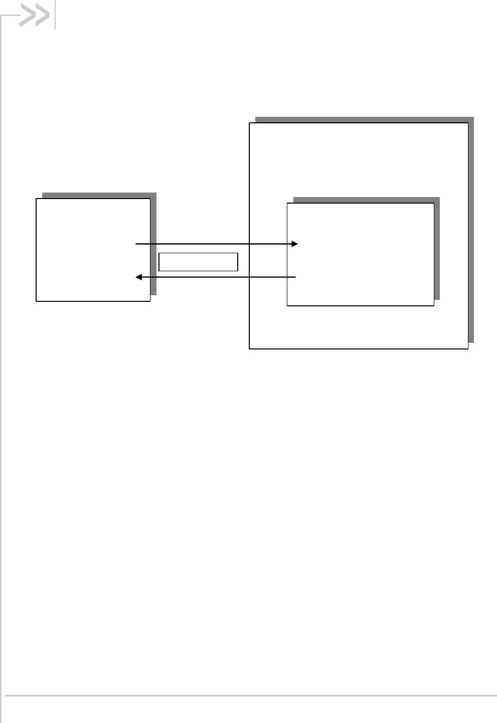
1.1. Scope of this Document
This document describes the AT-command based messages exchanged between an application and
Sierra Wireless products in order to manage GSM/GPRS related events or services.
Embedded module
AT
External
Application
Send AT command
Receive AT response
Serial Link

AT Commands Interface Guide for
Firmware 7.52
Rev. 1.0 Volume 1 March 7, 2014 6
1.2. Related Documents
This interface specification is based on the following recommendations:
[1] ETSI GSM 07.05: Digital cellular telecommunications system (Phase 2); Use of DTE-DCE
interface for Short Message Service (SMS) and Cell Broadcast Service (CBS)
[2] ETSI GSM 07.07: Digital cellular telecommunications system (Phase 2); AT command set for GSM
Mobile Equipment (ME)
[3] ITU-T Recommendation V.25 ter: Serial asynchronous automatic dialing and control
[4] ETSI GSM 03.40: Digital cellular telecommunications system (Phase 2); Technical implementation
of the Short Message Service (SMS) Point-to-Point (PP)
[5] ETSI GSM 03.38: Digital cellular telecommunications system (Phase 2); Alphabets and language-
specific information
[6] ETSI GSM 04.80: Digital cellular telecommunications system (Phase 2): Mobile radio interface
layer 3, Supplementary service specification, Formats and coding
[7] 3GPP 05.02: 3rd Generation Partnership Project; Technical Specification Group GSM/EDGE- Radio
Access Network; Multiplexing and multiple access on the radio path – 3GPP TS 05.02 V6.9.2
(2001-04)
[8] 3GPP 24.008: Mobile radio interface Layer 3 specification; Core network protocols; Stage 3
[9] 3GPP TS 11.11 Specification of the Subscriber Identity Module - Mobile Equipment (SIM-ME)
Interface
[10] 3GPP TS 05.08 Radio subsystem link control
[11] 3GPP TS 23.040 Technical realization of the Short Message Service (SMS);
[12] 3GPP TS 22.042 Network Identity and Time Zone (NITZ) service description; Stage 1
[13] 3GPP TS 51.011 Specification of the Subscriber Identity Module - Mobile Equipment (SIM-ME)
interface
[14] 3GPP TS 27-010 Terminal Equipment to User Equipment (TE-UE) multiplexer protocol
[15] 3GPP 23.014 Support of Dual Tone Multi Frequency (DTMF) signaling
[16] ISO 639 Langages Codes
[17] 3GPP 27 060 Packet domain; Mobile Station (MS) supporting Packet Switched services
[18] 3GPP TS 23.038 Alphabets and language-specific information
[19] 3GPP TS 27.005 Use of Data Terminal Equipment - Data Circuit terminating Equipment (DTE-
DCE) interface for Short Message Service (SMS) and Cell Broadcast Service (CBS)
[20] ETSI GSM 11.14 Digital cellular telecommunications system (Phase 2+); Specification of the SIM
Application Toolkit for the Subscriber Identity Module - Mobile Equipment (SIM - ME) interface
[21] 3GPP TS 23.003 Digital cellular telecommunications system (Phase 2+) (GSM); Numbering,
addressing and identification
[22] ETSI GSM 02.24 Digital cellular telecommunications system (Phase 2+) (GSM);Description of
Charge Advice Information (CAI)
[23] ETSI GSM 02.86 Digital cellular telecommunications system (Phase 2+) (GSM);Advice of Charge
(AoC) Supplementary Services - Stage 1
[24] ETSI GSM 02.90 Digital cellular telecommunications system (Phase 2+) (GSM);Unstructured
Supplementary Service Data (USSD) - Stage 1
[25] ETSI GSM 02.85 Digital cellular telecommunications system (Phase 2+) (GSM);Closed User
Group (CUG) Supplementary Services - Stage 1

AT Commands Interface Guide for
Firmware 7.52
Rev. 1.0 Volume 1 March 7, 2014 7
[26] 3GPP 27.007: Digital cellular telecommunications system (Phase 2+) (GSM); AT command set
for 3GPP User Equipment (UE) (Release 1999)
[27] 3GPP 23.107: Universal Mobile Telecommunications System (UMTS);QoS Concept and
Architecture (Release 1999)
[28] 3GPP 24.008: European digital cellular telecommunication system (Phase 2+). Mobile radio
interface layer 3 specification. (Release 1999)
[29] ETSI TS 102 221 "Smart Cards; UICC-Terminal interface; Physical and logical characteristics
(Release 1999)".

AT Commands Interface Guide for
Firmware 7.52
Rev. 1.0 Volume 1 March 7, 2014 8
1.3. ETSI Secretariat
The following addresses may be of use in obtaining the latest GSM/GPRS recommendations:
Postal address: F-06921 Sophia Antipolis CEDEX – France
Office address: 650 Route des Lucioles – Sophia Antipolis – Valbonne – France
Web address: http://www.etsi.org/
Tel: +33 4 92 94 42 00
Fax: +33 4 93 65 47 16

AT Commands Interface Guide for
Firmware 7.52
Rev. 1.0 Volume 1 March 7, 2014 9
1.4. Abbreviations and Definitions
1.4.1. Abbreviations
Abbreviation
Definition
ACM
Accumulated Call Meter
ADC
Analog Digital Converter
ADN
Abbreviated Dialing Number (Phonebook)
AMR
Adaptive Multi-Rate
AMR-FR
AMR Full Rate (full rate speech version 3)
AMR-HR
AMR Half Rate (half rate speech version 3)
AOC
Advice Of Charge
APN
Access Point Name
ARN
Address Resolution Protocol
ARFCN
Absolute Radio Frequency Channel Number
ASCII
American Standard Code for Information Interchange, Standard characters
table (1 byte coding)
AT
ATtention; Hayes Standard AT command Set
BCCH
Broadcast Channel
BER
Bit Err Rate
BM
Broadcoast Message Storage
CBM
Cell Broadcast Message
CB
Cell Broadcast
CCK
Corporate Control Key
CCM
Current Call Meter
CHV
Card Holder Verification
CHAP
Challenge handshake Authentication Protocol
CI
Cell Identifier
CLI
Client Line Identification
CLIP
Calling Line Identification Presentation
CLIR
Calling Line Identification Restriction
CNL
Cooperative Network List
CODEC
Coder Decoder
COLP
Connected Line Identification Presentation
CPHS
Common PCN Handset Specification
CPU
Central Processing Unit
CSD
Circuit Switched Data
CSP
Customer Service Profile
CTM
Cellular Text telephone Modem
CTS
Clear To Send signal
CUG
Closed User Group
DAC
Digital to Analog Converter

AT Commands Interface Guide for
Firmware 7.52
Rev. 1.0 Volume 1 March 7, 2014 10
Abbreviation
Definition
DTR
Data Terminal Ready
DCS
Digital Cellular System
DCE
Data Circuit Equipment
DCD
Data Carrier Detect
DLC
Data Link Connection
DLCI
Data Link Connection Identifier
DM
Device Management
DNS
Domain Name System
DSR
Data Set Ready
DTE
Date Terminal Equipment
DTMF
Dual Tone Multi-Frequency
DTR
Data Terminal Ready
ECC
Emergency Call Codes
ECM
Error Correction Mode
ECT
Explicit Call Transfer
EDGE
Enhanced Data rates for GSM Evolution
EEPROM
Electrically Erasable Programming Only Memory
EF
Elementary Files
EFR
Enhanced Full Rate (full rate speech version 2)
EGPRS
Enhanced GPRS
ENS
Enhanced Network Selection
E-ONS
Enhanced Operator Name Service
ERMES
European Radio Messaging System
ETSI
European Telecommunications Standards Institute
FD
FIFO depth
FDN
Fixed Dialing Number (Phonebook)
FR
Full Rate (full rate speech version 1)
GERAN
GSM EDGE Radio Access Network
GPIO
General Purpose Input Output
GPRS
General Packet Radio Service
GSM
Global System for Mobile communication
HDLC
High-level Data Link Control
HFR
High Frequency Regeneration
HLR
Home Location Register
HR
Half Rate (half rate speech version 1)
HSDPA
High Speed Downlink Packet Access
HSUPA
High Speed Uplink Packet Access
ID
IDentifier
IETF
Internet TEngineering Task ForceT
IMEI
International Mobile Equipment Identity
IMSI
International Mobile Subscriber Identity
IN/OUT/IN_OUT
In, out or In Out. see glossary
I/O
Input/Output

AT Commands Interface Guide for
Firmware 7.52
Rev. 1.0 Volume 1 March 7, 2014 11
Abbreviation
Definition
IP
Internet Protocol
LAC
Local Area Code
LED
Light Emitting Diode
LND
Last Number Dialed
LP
Language Preferred
LPI
Lines Per Inch
M
Mandatory
MCC
Mobile Country Code
ME
Mobile Equipment
MMI
Man Machine Interface
MNC
Mobile Network Code
MNP
Microcom Networking Protocol
MO
Mobile Originated
MOC
Mobile Originated Call (outgoing call)
MS
Mobile Station
MSB
Most Significant Bit
MSISDN
Mobile Station International ISDN Number
MT
Mobile Terminal
MTC
Mobile Terminated Call (incoming call)
N.A.
Not applicable
NCK
Network Control Key
NITZ
Network Information and Time Zone
NSCK
Network Subset Control Key
NTC
Negative Temperature Coefficient
N.U.
Not used
O
Optional
OA
Outgoing Access
OPL
Operator PLMN List
OS
Operating System
OTA
Over the Air
PAD
Portable Application Description
PAP
Password Authentication Protocol
PC
Personal Computer
PCCP
PC character set Code Page
PCK
Personalization Control Key
PCL
Power Control Level
PCM
Protection Circuit Module
PCN
Personal Communication Network
PCS 1900
Personal Communication Service (GSM system offering 148 full duplex voice
channels per cell)
PDP
Packet Data Protocol
PDU
Protocol Description Unit
PIN
Personal Identification Number
PLMN
Public Land Mobile Networks

AT Commands Interface Guide for
Firmware 7.52
Rev. 1.0 Volume 1 March 7, 2014 12
Abbreviation
Definition
PNN
PLMN Network Name
PPP
Point-to-Point Protocol
Peer to Peer
PSTN
Public Switched Telephone Network
PTS
Product Technical Specification
PUCT
Price per Unit and Currency Table
PUK
PIN Unlock Key
QoS
Quality of Service
RAM
Random Access Memory
RDMS
Remote Device Management Services
RI
Ring Indicator
RIL
Radio Interface Layer
RLP
Radio Link Protocol
RSSI
Received Signal Strength Indication
RTS
Ready To Send signal
RX
Reception
SAP
Service Access Point
SC
Service Center
SDU
Service Data Unit
SIM
Subscriber Information Module
SMSR
Short Message Status Report
SMS
Short Message Service
SS
Supplementary Services
SPCK
Service Provider Control Key
SPN
Service Provider Name
STK
Sim ToolKit
SVN
Software Version Number
TA
Terminal Adaptor
TBF
Temporary Block Flow
TE
Terminal Equipment
TTY
TeleTYpe
TON/NPI
Type Of Number/Numbering Plan Identification
TX
Transmission
UART
Universal Asynchronous Receiver Transmitter
UCS2
Universal Character Set 2 Character table (2-byte coding)
UDUB
User Determined User Busy
UIH
Unnumbered Information with Header check
UMTS
Universal Mobile Telecommunication System
USB
Universal Serial Bus
USSD
Unstructered Supplementary Service Data
UTRAN
Universal Terrestrial Radio Access Network
AT Commands Interface Guide for
Firmware 7.52
Rev. 1.0 Volume 1 March 7, 2014 13
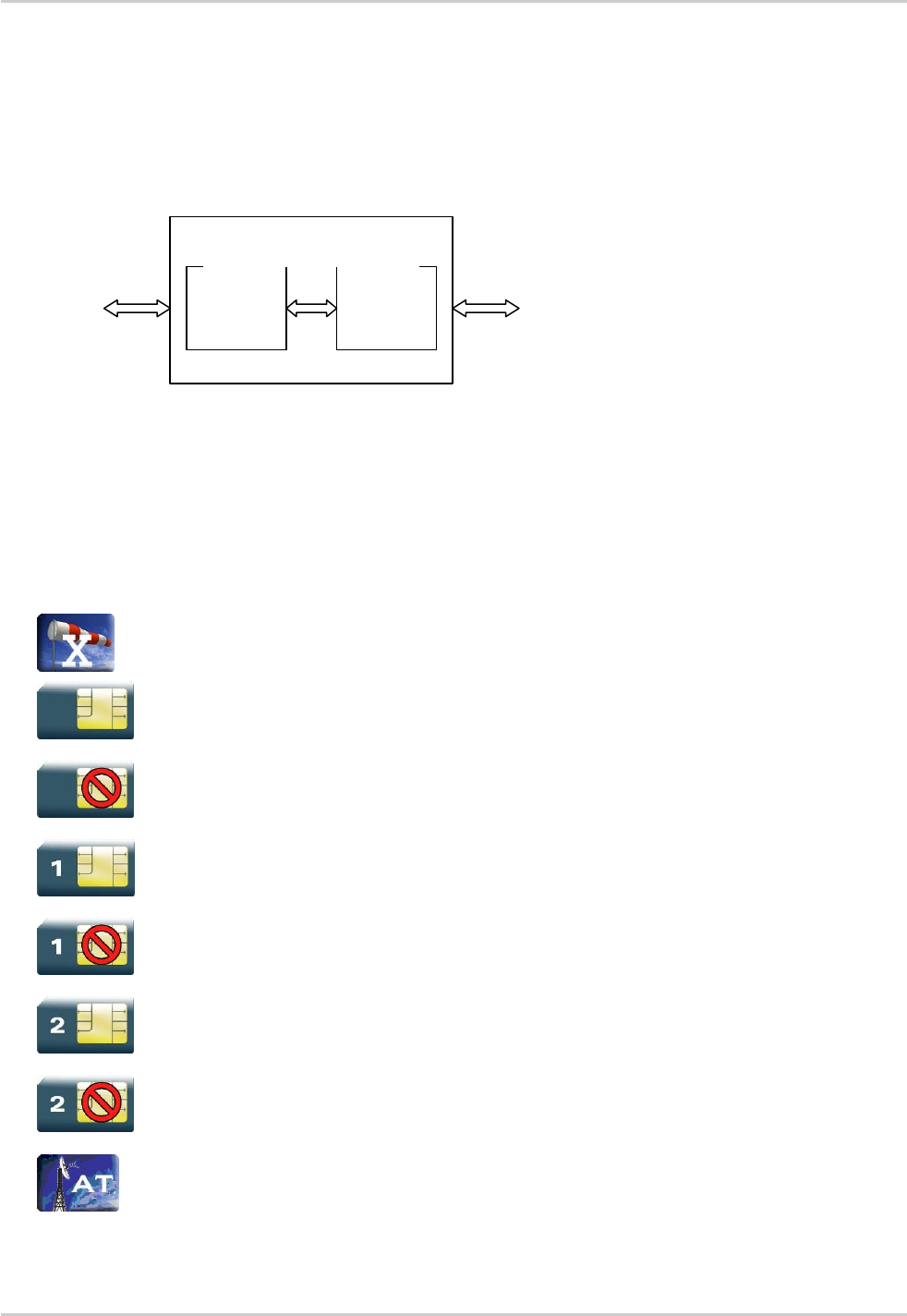
1.4.2. Definitions
The words "Mobile Station" (MS) or "Mobile Equipment" (ME) are used for mobile terminals
supporting GSM/GPRS services.
Terminal Equipment is the Man-Machine Interface of a GSM/GPRS device (modem or handset). A TE
can be a handset MMI or the AT command line interface.
User
GSM/GPRS network
ME
TE
Sierra Wireless product
A call from a GSM/GPRS mobile station to the PSTN is called a "mobile originated call" (MOC) or
"outgoing call", and a call from a fixed network to a GSM/GPRS mobile station is called a "mobile
terminated call" (MTC) or "incoming call"
In this document, the word "product" refers to any Sierra Wireless product supporting the AT
commands interface.
1.4.3. Logos
This picture indicates the +WIND indication from which the AT command is allowed. X values
can be: 1, 3, 4, 16.
This picture indicates that a SIM card must be inserted to support the AT command.
This picture indicates that an AT command is supported even if the SIM card is absent.
This picture indicates that the PIN 1 /CHV 1 code must be entered to support the AT command.
This picture indicates that an AT command is supported even if the PIN 1 /CHV 1 code is not
entered.
This picture indicates that the PIN 2 /CHV 2 code must be entered to support the AT command.
This picture indicates that an AT command is supported even if the PIN 2/CHV 2 code is not
entered.
This picture indicates that the AT command is available using the AirPrime Management
Services.

AT Commands Interface Guide for
Firmware 7.52
Rev. 1.0 Volume 1 March 7, 2014 14
1.5. AT Commands Presentation Rules
The AT commands are presented in the present documentation as follows:
A "Description" section provides general information on the AT command (or response)
behaviour.
A "Syntax" section describes the command and response syntaxes and all parameters
description.
A "Parameters and Defined Values" section describes all parameters and values.
A "Parameter Storage" presents the command used to store the parameter value and/or the
command used to restore the parameter default value.
An "Examples" section presents the real use of the described command.
A "Note" section can also be included indicating some remarks about the command use.
Figures are provided where necessary

AT Commands Interface Guide for
Firmware 7.52
Rev. 1.0 Volume 1 March 7, 2014 15
1.6. AT Commands Applicability
The following table presents all available AT Commands, and which are applicable to each product.
The table is marked with the indicators below.
-: Fully supported
-: Partially supported or with specific behavior – Please see the Notes section of the corresponding
AT command for complete information.
-: Not supported.
Description
Command
Q2686,
Q2687,
SL6087
AR6220,
WP6200
SL8080T,
SL8082T,
SL8084T
Q2698
Basic Commands
Attention Command
-
-
-
-
Available Repeat Last Command
A/
-
-
-
-
Identifications commands
Manufacturer Identification
+CGMI
-
-
-
-
Request Model Identification
+CGMM
-
-
-
-
Hardware Version
+WHWV
-
-
-
-
Date of Production
+WDOP
-
-
-
-
Write IMEI
+WIMEI
-
-
-
-
Embedded Serial Number
+WMSN
-
-
-
-
Product Serial Number
+CGSN
-
-
-
-
Request Revision Identification
+CGMR
-
-
-
-
Request identification
information
I
-
-
-
-
Write IMEI SVN
+WSVN
-
-
-
-
Capabilities List
+GCAP
-
-
-
-
Open-AT Framework Commands
Downloading
+WDWL
-
-
-
-
Open-AT control
+WOPEN
-
-
-
-

AT Commands Interface Guide for
Firmware 7.52
Rev. 1.0 Volume 1 March 7, 2014 16
Description
Command
Q2686,
Q2687,
SL6087
AR6220,
WP6200
SL8080T,
SL8082T,
SL8084T
Q2698
Tasks resume
+WOPENRES
-
-
-
-
Global Configuration Commands
Report Mobile Equipment Errors
+CMEE
-
-
-
-
Hardware Configuration
+WHCNF
-
-
-
-
Embedded Module Behaviour
Configuration
+WBHV
-
-
-
-
Features Management
+WFM
-
-
-
-
Commercial Feature
Management
+WCFM
-
-
-
-
Sierra Wireless SLEEP Mode
+W32K
-
-
-
-
Power Off
+CPOF
-
-
-
-
Set Phone Functionality
+CFUN
-
-
-
-
Sierra Wireless Reset
+WRST
-
-
-
-
Save Configuration
&W
-
-
-
-
Restore Factory Settings
&F
-
-
-
-
Default Configuration
ATZ
-
-
-
-
Display Configuration
&V
-
-
-
-
Sierra Wireless Custom
Character Set
+WCCS
-
-
-
-
Select TE Character Set
+CSCS
-
-
-
-
Sierra Wireless Phonebook
Character Set
+WPCS
-
-
-
-
Set Language
+CLAN
-
-
-
-
Lanaguage Event
+CLAE
-
-
-
-
Select Tyoe of Address
+CSTA
-
-
-
-
Cellular Text Telephone Modem
+WCTM
-
-
-
-
Sierra Wireless Debug Interface
Management
+WDEBUG
-
-
-
-

AT Commands Interface Guide for
Firmware 7.52
Rev. 1.0 Volume 1 March 7, 2014 17
Description
Command
Q2686,
Q2687,
SL6087
AR6220,
WP6200
SL8080T,
SL8082T,
SL8084T
Q2698
Digital to Analog Converter
+DAC
-
-
-
-
Automatic Boost Mode
+WCPS
-
-
-
-
Auto Shutdown
+WASR
-
-
-
-
IP Stack Settings
+WIPS
-
-
-
-
Sierra Wireless Development
Mode
+WDM
-
-
-
-
Embedded Module Status Commands
General Indications
+WIND
-
-
-
-
Phone Activity Status
+CPAS
-
-
-
-
SIM Holder Status
+WSHS
-
-
-
-
Indicator Control
+CIND
-
-
-
-
Mobile Equipment Event
Reporting
+CMER
-
-
-
-
Mobile Equipment Control Mode
+CMEC
-
-
-
-
Sierra Wireless Status Request
+WSTR
-
-
-
-
Temperature Monitoring Report
+WTMR
-
-
-
-
Temperature Command
+WTEMP
-
-
-
-
Sierra Wireless Critical Error
Report
+WCER
-
-
-
-
Serial Port Commands
Echo
ATE
-
-
-
-
Fixed DTE Rate
+IPR
-
-
-
-
DTE-DCE Character Framing
+ICF
-
-
-
-
DTE-DCE Local Flow Control
+IFC
-
-
-
-
Result Code Suppression
ATQ
-
-
-
-
DCE Response Format
ATV
-
-
-
-

AT Commands Interface Guide for
Firmware 7.52
Rev. 1.0 Volume 1 March 7, 2014 18
Description
Command
Q2686,
Q2687,
SL6087
AR6220,
WP6200
SL8080T,
SL8082T,
SL8084T
Q2698
Set DCD Signal
&C
-
-
-
-
Set DTR Signal
&D
-
-
-
-
Set DSR Signal
&S
-
-
-
-
Sierra Wireless Ring Indicator
Mode
+WRIM
-
-
-
-
Back to online mode
ATO
-
-
-
-
Multi-flow Management
+WMFM
-
-
-
-
Multiplexing Mode
+CMUX
-
-
-
-
Sierra Wireless USB
Configuration
+WUSB
-
-
-
-
Security Commands
Enter PIN
+CPIN
-
-
-
-
Enter PIN2
+CPIN2
-
-
-
-
PIN Remaining Attempt Number
+CPINC
-
-
-
-
Change Password
+CPWD
-
-
-
-
Facility Lock
+CLCK
-
-
-
-
Sierra Wireless LoCK
+WLCK
-
-
-
-
Time Management Commands
Clock Management
+CCLK
-
-
-
-
Alarm Management
+CALA
-
-
-
-
GSM Network Commands
Signal Quality
+CSQ
-
-
-
-
Network Registration
+CREG
-
-
-
-
Cell Environment description
+CCED
-
-
-
-
Sierra Wireless Multi-band
Selection Command
+WMBS
-
-
-
-

AT Commands Interface Guide for
Firmware 7.52
Rev. 1.0 Volume 1 March 7, 2014 19
Description
Command
Q2686,
Q2687,
SL6087
AR6220,
WP6200
SL8080T,
SL8082T,
SL8084T
Q2698
Registration Control
+WREGC
-
-
-
-
Sierra Wireless Location
+WLOC
-
-
-
-
Sierra Wireless Scan
+WSCAN
-
-
-
-
Abort Command
+WAC
-
-
-
-
Band Services command
+WUBS
-
-
-
-
Wireless Service Management
+WWSM
-
-
-
-
Wireless Power Level
+WPOW
-
-
-
-
Error Code
$ARMEE
-
-
-
-
Call Control Commands
Dial Command to a specific
number
D
-
-
-
-
Direct Dial Command using
phonebook index
D
-
-
-
-
Direct Dial Command using a
phonebook entry name
D
-
-
-
-
Redial Last Telephone Number
DL
-
-
-
-
Answer a Call
A
-
-
-
-
Hang-Up Command
H
-
-
-
-
Sierra Wireless Hang-up
+WATH
-
-
-
-
Remote disconnection
-
-
-
-
Extended Error Report
+CEER
-
-
-
-
Automatic Dialing with DTR
%Dn
-
-
-
-
Automatic Answer
S0
-
-
-
-
Incoming Call Bearer
+CICB
-
-
-
-
Single Numbering Scheme
+CSNS
-
-
-
-
Service Reporting Control
+CR
-
-
-
-

AT Commands Interface Guide for
Firmware 7.52
Rev. 1.0 Volume 1 March 7, 2014 20
Description
Command
Q2686,
Q2687,
SL6087
AR6220,
WP6200
SL8080T,
SL8082T,
SL8084T
Q2698
Cellular Result Codes
+CRC
-
-
-
-
Data Commands
Bearer Type Selection
+CBST
-
-
-
-
DTE-DCE Local Rate Reporting
+ILRR
-
-
-
-
Radio Link Protocol Parameters
+CRLP
-
-
-
-
Other Radio Link Parameters
+DOPT
-
-
-
-
Select Mode
+FCLASS
-
-
-
-
Select Data Compression
%C
-
-
-
-
V42 Bis Data Compression
+DS
-
-
-
-
V42 Bis Data Compression
Report
+DR
-
-
-
-
Select Data Error Correcting
Mode
\N
-
-
-
-
GPRS Commands
GPRS Mobile Station Class
+CGCLASS
-
-
-
-
GPRS parameters customization
+WGPRS
-
-
-
-
Define PDP Context
+CGDCONT
-
-
-
-
GPRS Attach or Detach
+CGATT
-
-
-
-
PDP Context Activate or
Deactivate
+CGACT
-
-
-
-
Request GPRS IP Service D
D
-
-
-
-
Enter Data State
+CGDATA
-
-
-
-
GPRS Hang-Up Command GH
GH
-
-
-
-
Network requested PDP context
activation
-
-
-
-
Manual Response to a Network
Request for PDP Manual
Context Activation
+CGANS
-
-
-
-

AT Commands Interface Guide for
Firmware 7.52
Rev. 1.0 Volume 1 March 7, 2014 21
Description
Command
Q2686,
Q2687,
SL6087
AR6220,
WP6200
SL8080T,
SL8082T,
SL8084T
Q2698
Automatic Response to a
Network Request for PDP
Context Activation
+CGAUTO
-
-
-
-
Quality of Service Profile
(Minimum acceptable)
+CGQMIN
-
-
-
-
Quality of Service Profile
(Requested)
+CRQREQ
-
-
-
-
PDP Context Modify
+CGCMOD
-
-
-
-
GPRS network registration
status
+CGREG
-
-
-
-
GPRS Event reporting
+CGEREP
-
-
-
-
Select Service for MO SMS
Messages
+CGSMS
-
-
-
-
Show PDP Address
+CGPADDR
-
-
-
-
GSM/GPRS Tx Burst Indication
+WTBI
-
-
-
-
3G Quality of Service Profile
(Requested)
+CGEQREQ
-
-
-
-
3G Quality of Service Profile
(Minimum acceptable)
+CGEQMIN
-
-
-
-
3G Quality of Service Profile
(Negotiated)
+CGEQNEG
-
-
-
-
Authentication Protocol
+WPPP
-
-
-
-
PLMN Commands
Selection of Preferred PLMN list
+CPLS
-
-
-
-
Operator Selection
+COPS
-
-
-
-
Preferred Operator List
+CPOL
-
-
-
-
Operator List Management
+WOLM
-
-
-
-
Read Operator Name
+WOPN
-
-
-
-
Read Operator Name
+COPN
-
-
-
-
Automatic Time Zone Update
+CTZU
-
-
-
-
AT&T Command
+PACSP
-
-
-
-

AT Commands Interface Guide for
Firmware 7.52
Rev. 1.0 Volume 1 March 7, 2014 22
Description
Command
Q2686,
Q2687,
SL6087
AR6220,
WP6200
SL8080T,
SL8082T,
SL8084T
Q2698
Phonebooks Commands
Select Phonebook Memory
Storage
+CPBS
-
-
-
-
Contact Selector
+WCOS
-
-
-
-
Write Phonebook Entry
+CPBW
-
-
-
-
Read Phonebook Entries
+CPBR
-
-
-
-
Find Phonebook Entries
+CPBF
-
-
-
-
Phonebook Phone Search
+CPBP
-
-
-
-
Move Action in Phonebook
+CPBN
-
-
-
-
Create and Delete a Phonebook
Group
+WPGW
-
-
-
-
Read a Phonebook Group
+WPGR
-
-
-
-
Settings of a Group
+WPGS
-
-
-
-
Delete Calls Phonebook
+WDCP
-
-
-
-
Subscriber Number
+CNUM
-
-
-
-
Set Voice Mail Number
+CSVM
-
-
-
-
Avoid Phonebook Init
+WAIP
-
-
-
-
Short Message Commands
Select Message Service
+CSMS
-
-
-
-
New Message Indication
+CNMI
-
-
-
-
Set Text Mode Parameters
+CSMP
-
-
-
-
Preferred Message Format
+CMGF
-
-
-
-
Preferred Message Storage
+CPMS
-
-
-
-
Service Center Address
+CSCA
-
-
-
-
Show Text Mode Parameters
+CSDH
-
-
-
-
More Messages to Send
+CMMS
-
-
-
-

AT Commands Interface Guide for
Firmware 7.52
Rev. 1.0 Volume 1 March 7, 2014 23
Description
Command
Q2686,
Q2687,
SL6087
AR6220,
WP6200
SL8080T,
SL8082T,
SL8084T
Q2698
Send Message
+CMGS
-
-
-
-
Write Message to Memory
+CMGW
-
-
-
-
Send Message From Storage
+CMSS
-
-
-
-
Read Message
+CMGR
-
-
-
-
List Message
+CMGL
-
-
-
-
Delete Message
+CMGD
-
-
-
-
New Message
Acknowledgement
+CNMA
-
-
-
-
Message Status Modification
+WMSC
-
-
-
-
Un-change SMS Status
+WUSS
-
-
-
-
Message Overwriting
+WMGO
-
-
-
-
Copy Messages
+WMCP
-
-
-
-
Save Settings
+CSAS
-
-
-
-
Restore Settings
+CRES
-
-
-
-
Select Cell Broadcast Message
Types
+CSCB
-
-
-
-
Cell Broadcast Message
Identifiers
+WCBM
-
-
-
-
SIM Commands
Card Identification
+CCID
-
-
-
-
Request IMSI
+CIMI
-
-
-
-
Generic SIM Access
+CSIM
-
-
-
-
Restricted SIM Access
+CRSM
-
-
-
-
Write Language Preference
+WLPW
-
-
-
-
Read Language Preference
+WLPR
-
-
-
-

AT Commands Interface Guide for
Firmware 7.52
Rev. 1.0 Volume 1 March 7, 2014 24
Description
Command
Q2686,
Q2687,
SL6087
AR6220,
WP6200
SL8080T,
SL8082T,
SL8084T
Q2698
SIM Toolkit Commands
SIM ToolKit Set Facilities
+STSF
-
-
-
-
SIM ToolKit Indication
+STIN
-
-
-
-
SIM ToolKit Get Information
+STGI
-
-
-
-
SIM ToolKit Give Response
+STGR
-
-
-
-
SIM ToolKit Control Response
+STCR
-
-
-
-
SIM ToolKit Indication
+STRIL
-
-
-
-
Supplementary Services Commands
List Current Calls
+CLCC
-
-
-
-
Call Related Supplementary
Services
+CHLD
-
-
-
-
Calling Line Identification
Presentation
+CLIP
-
-
-
-
Calling Line Identification
Restriction
+CLIR
-
-
-
-
Connected Line Identification
Presentation
+COLP
-
-
-
-
Supplementary Service
Notifications
+CSSN
-
-
-
-
Unstructured Supplementary
Service Data
+CUSD
-
-
-
-
Call Forwarding
+CCFC
-
-
-
-
Call Waiting
+CCWA
-
-
-
-
Keypad Control
+CKPD
-
-
-
-
Advice Of Charge
+CAOC
-
-
-
-
Accumulated Call Meter
+CACM
-
-
-
-
Accumulated Call Meter
Maximum
+CAMM
-
-
-
-
Price per UNIT and Currency
Table
+CPUC
-
-
-
-

AT Commands Interface Guide for
Firmware 7.52
Rev. 1.0 Volume 1 March 7, 2014 25
Description
Command
Q2686,
Q2687,
SL6087
AR6220,
WP6200
SL8080T,
SL8082T,
SL8084T
Q2698
Closed User Group
+CCUG
-
-
-
-
Audio Commands
Speaker and microphone
selection
+SPEAKER
-
-
-
-
Ringer Sound Level
+CRSL
-
-
-
-
Microphone Mute Control
+CMUT
-
-
-
-
Loudspeaker Volume Level
+CLVL
-
-
-
-
Side Tone Modification
+SIDET
-
-
-
-
Gain Control
+VGR
-
-
-
-
Gain Control
+VGT
-
-
-
-
Digital Gain Control
+WDGR
-
-
-
-
Digital Gain Control
+WDGT
-
-
-
-
Audio Filter Command
+WADF
-
-
-
-
Echo Cancellation
+ECHO
-
-
-
-
Sierra Wireless Voice Rate
+WVR
-
-
-
-
DTMF Signals
+VTD
-
-
-
-
DTMF Signals
+VTS
-
-
-
-
Play Tone
+WTONE
-
-
-
-
Play DTMF tone
+WDTMF
-
-
-
-
DTMF Detecttion Mode
+WDDM
-
-
-
-
Set Standard Tone
+WSST
-
-
-
-
Ring Melody Playback
+CRMP
-
-
-
-
Sierra Wireless Change Default
Melody
+WCDM
-
-
-
-
Sierra Wireless Change Default
Player
+WCDP
-
-
-
-

AT Commands Interface Guide for
Firmware 7.52
Rev. 1.0 Volume 1 March 7, 2014 26
Description
Command
Q2686,
Q2687,
SL6087
AR6220,
WP6200
SL8080T,
SL8082T,
SL8084T
Q2698
Initialize Voice Parameters
+VIP
-
-
-
-
Auto-tests
&T
-
-
-
-
Auto Diagnostic Start
+WADS
-
-
-
-
I/O Commands
Input/Output Management
+WIOM
-
-
-
-
Read GPIO value
+WIOR
-
-
-
-
Write GPIO value
+WIOW
-
-
-
-
Sierra Wireless Interrupt Pin
Configuration
+WIPC
-
-
-
-
Battery Commands
Analog Digital Converters
Measurements
+ADC
-
-
-
-
Sierra Wireless Battery Charge
Management
+WBCM
-
-
-
-
Sierra Wireless Autodiag
+WDIAG
-
-
-
-
CPHS Commands
CPHS command
+CPHS
-
-
-
-
Sierra Wireless CPHS Mail Box
Number
+WMBN
-
-
-
-
Sierra Wireless Alternate Line
Service
+WALS
-
-
-
-
Fax Commands
Transmit Speed
+FTM
-
-
-
-
Receive Speed
+FRM
-
-
-
-
HDLC Transmit Speed
+FTH
-
-
-
-
HDLC Receive Speed
+FRH
-
-
-
-
Stop Transmission and Wait
+FTS
-
-
-
-
Receive Silence
+FRS
-
-
-
-

AT Commands Interface Guide for
Firmware 7.52
Rev. 1.0 Volume 1 March 7, 2014 27
Description
Command
Q2686,
Q2687,
SL6087
AR6220,
WP6200
SL8080T,
SL8082T,
SL8084T
Q2698
Fax class 2 Commands
Transmit Data
+FTD
-
-
-
-
Receive Data
+FDR
-
-
-
-
Transmit Page Punctuation
+FET
-
-
-
-
Page Transfer Status
Parameters
+FTPS
-
-
-
-
Terminate Session
+FK
-
-
-
-
Page Transfer Bit Order
+FBOR
-
-
-
-
Buffer Size Report
+FBUF
-
-
-
-
Copy Quality Checking
+FCQ
-
-
-
-
Capability to Receive
+FCR
-
-
-
-
Current Session Parameters
+FDIS
-
-
-
-
DCE Capabilities Parameters
+FDCC
-
-
-
-
Local ID String
+FLID
-
-
-
-
Page Transfer Timeout
Parameter
+FPHCTO
-
-
-
-
Additional Fax Class 2 indication
messages
-
-
-
-
Remote Device Management Services
Commands
Device Services Configuration
+WDSC
-
-
-
-
Device Services Error
+WDSE
-
-
-
-
Device Services Fallback
+WDSF
-
-
-
-
Device Services General status
+WDSG
-
-
-
-
Device Services Reply
+WDSR
-
-
-
-
Device Services Session
+WDSS
-
-
-
-
Device Services Indications
+WDSI
-
-
-
-

AT Commands Interface Guide for
Firmware 7.52
Rev. 1.0 Volume 1 March 7, 2014 28
Description
Command
Q2686,
Q2687,
SL6087
AR6220,
WP6200
SL8080T,
SL8082T,
SL8084T
Q2698
Device Services Bootstrap
+WDSB
-
-
-
-
Device Services Host
+WDSH
-
-
-
-
Device Services Local Download
+WDSD
-
-
-
-
Device Services Over-The-Air
+WDSO
-
-
-
-

Rev. 1.0 Volume 1 March 7, 2014 29
2. AT Commands Features
2.1. Sierra Wireless Line Settings
A serial link handler is set with the following default values (factory settings):
speed according to customer choice at order time,
8 bits data,
1 stop bit,
no parity,
RTS/CTS flow control.
Please use the +IPR, +IFC and +ICF commands to change these settings.
2.2. Command Line
Commands always start with AT and finish with a <CR> character, excepted A/ command.
2.3. Information Responses and Result Codes
Responses start and end with <CR><LF>, except for the ATV0 DCE response format and the ATQ1
(result code suppression) commands.
If command syntax is incorrect, the "ERROR" string is returned.
If command syntax is correct but transmitted with wrong parameters, the "+CME ERROR:
<Err>" or "+CMS ERROR: <SmsErr>" strings is returned with adequate error codes if CMEE
was previously set to 1. By default, CMEE is set to 0, and the error message is only
"ERROR".
If the command line has been executed successfully, an "OK" string is returned.
In some cases, such as "AT+CPIN?" or (unsolicited) incoming events, the product does not return the
"OK" string as a response.
In the following examples <CR> and <CR><LF> are intentionally omitted.
Note: The command syntax accepts negative parameters. If the command parameter is negative and out of
the acceptable range, the "+CME ERROR: 3" string is returned if CMEE was previously set to 1.
2.4. Proprietary Commands
When a command is Sierra Wireless proprietary, the information is indicated in the command
description.

AT Commands Interface Guide for
Firmware 7.52
Rev. 1.0 Volume 1 March 7, 2014 30
2.5. SIM Insertion and Removal
Note: This function is not supported on AirPrime SL808xT embedded module.
SIM card insertion and removal procedures are supported. There are software functions relying on
positive reading of the hardware SIM detect pin. This pin state (open/closed) is permanently
monitored.
When the SIM detect pin indicates that a card is present in the SIM connector, the product tries to set
up a logical SIM session. The logical SIM session will be set up or not depending on whether the
detected card is a SIM card or not. The AT+CPIN? command delivers the following responses:
If the SIM detect pin indicates "absent", the response to AT+CPIN? is "+CME ERROR: 10"
(SIM not inserted).
If the SIM detect pin indicates "present", and the inserted card is a SIM card, the response to
AT+CPIN? is "+CPIN: xxx" depending on SIM PIN state.
If the SIM detect pin indicates "present", and the inserted card is not a SIM card, the response
to AT+CPIN? is "+CME ERROR: 10".
These last two states are not provided immediately due to background initialization. Between
the hardware SIM detect pin indicating "present" and the final results, the AT+CPIN? sends
"+CME ERROR: 515" (Please wait, init in progress).
When the SIM detect pin indicates card absence, and if a SIM card was previously inserted, an IMSI
detach procedure is performed, all user data is removed from the product (phonebooks, SMS etc.).
The product then switches to emergency mode.
2.6. Background Initialization
After entering the PIN 1/CHV 1, some SIM user data files are loaded into the product (phonebooks,
SMS status, etc.). Please be aware that it might take some time to read a large phonebook.
The AT+CPIN? command response occurs after PIN checking. After this response user data is
loaded in background. This means that some data may not be available just when PIN entry is
confirmed by "OK". The reading of phonebooks will then be refused by "+CME ERROR: 515" or
"+CMS ERROR: 515" meaning, "Please wait, service is not available yet, init in progress".
This type of answer may be sent by the product at several points:
when trying to execute another AT command before the previous one is completed (before
response),
when switching from ADN to FDN (or FDN to ADN) and trying to read the relevant phonebook
immediately,
when asking for +CPIN? status immediately after SIM insertion and before the product has
determined if the inserted card is a valid SIM card.

AT Commands Interface Guide for
Firmware 7.52
Rev. 1.0 Volume 1 March 7, 2014 31
2.7. Length of Phone Numbers
Phone numbers can be made of up to 80 digits. The 20 first digits are stored in SIM, in the phonebook
file (EFADN, EFFDN or EFLND) corresponding to the selected phonebook. The next digits are stored in
other extension SIM files (EFEXT1 or EFEXT2).
As an example:
Number of digits
Nb of records in EFADN
Nb of free records in EFEXT1
1 to 20
1
0
21 to 40
1
1
41 to 60
1
2
61 to 80
1
3
If there is no more free records in the EFEXT1, the behaviour is:
if user tries to store an entry of more than 20 digits: +CME ERROR: 20,
if user tries to dial a number of more than 20 digits: +CME ERROR: 20.
As the maximum length for the numbers (in ADN, FDN, LND) phonebooks is 80 digits:
if user tries to dial a number of more than 80 digits: +CME ERROR: 26.
Before performing a call, the number of free records in the EFEXT1 is checked, to be able to store the
dialed number.
if there are free records left, the call is setup
otherwise, +CME ERROR: 20 errors are returned (memory full).
Please refer to Recommendation 3GPP 11.11 [9] for more details.
2.8. Bad Software Message
The Sierra Wireless embedded module is designed to be downloaded with specific software. When
the user has to take in charge the software download, it is necessary to be sure that the compatible
software is downloaded. If the software downloaded is either corrupt or non-compatible, the message
BAD SOFTWARE is displayed. To remedy, reinstall the initial specific software version.
Note: If the embedded module is still displaying BAD SOFTWARE, only Sierra Wireless or a distributor can
recover it.

AT Commands Interface Guide for
Firmware 7.52
Rev. 1.0 Volume 1 March 7, 2014 32
2.9. Commands Concatenation
The Sierra Wireless embedded module supports basic AT commands and extended AT commands
concatenation.
2.9.1. Basic Syntax Commands
2.9.1.1. Basic Syntax Command Format
The format of Basic Syntax commands, except for the D and S commands, is as follows:
<command>[<number>]
where <command> is either a single character, or the "&" character (IA5 2/6) followed by a single
character. Characters used in <command> shall be taken from the set of alphabetic characters.
<number> may be a string of one or more characters from "0" through "9" representing a decimal
integer value. Commands that expect a <number> are noted in the description of the command (see
clause 6). If a command expects <number> and it is missing (<command> is immediately followed in
the command line by another <command> or the termination character), the value "0" is assumed. If a
command does not expect a <number> and a number is present, an ERROR is generated. All leading
"0"s in <number> are ignored by the DCE.
Additional commands may follow a command (and associated parameter, if any) on the same
command line without any character required for separation. The actions of some commands cause
the remainder of the command line to be ignored (e.g., A).
See the D command for details on the format of the information that follows it.
2.9.1.2. S-parameters
Commands that begin with the letter "S" constitute a special group of parameters known as "S-
parameters". These differ from other commands in important respects. The number following the "S"
indicates the "parameter number" being referenced. If the number is not recognized as a valid
parameter number, an ERROR result code is issued.
Immediately following this number, either a "?" or "=" character (IA5 3/15 or 3/13, respectively) shall
appear. "?" is used to read the value of the indicated S-parameter; "=" is used to set the S-parameter
to a new value.
S<parameter_number>?
S<parameter_number>= [<value>]
If the "=" is used, the new value to be stored in the S-parameter is specified in decimal following the
"=". If no value is given (i.e., the end of the command line occurs or the next command follows
immediately), the S-parameter specified may be set to 0, or an ERROR result code issued and the
stored value left unchanged. The ranges of acceptable values are given in the description of each S-
parameter.
If the "?" is used, the DCE transmits a single line of information text to the DTE. For S-parameters
defined in this Recommendation, the text portion of this information text consists of exactly three
characters, giving the value of the S-parameter in decimal, with leading zeroes included.

AT Commands Interface Guide for
Firmware 7.52
Rev. 1.0 Volume 1 March 7, 2014 33
2.9.1.3. Concatenating Commands after Extended Syntax
Commands
Additional commands may follow an extended syntax command on the same command line if a
semicolon (";", IA5 3/11) is inserted after the preceding extended command as a separator. The
semicolon is not necessary when the extended syntax command is the last command on the
command line.
2.9.1.4. Concatenating Commands after Basic Format
Commands
Extended syntax commands may appear on the same command line after a basic syntax command
without a separator, in the same manner as concatenation of basic syntax commands.

Rev. 1.0 Volume 1 March 7, 2014 34
3. Basic Commands
3.1. Attention Command AT
3.1.1. Description
This command always returns OK.
3.1.2. Syntax
Action command
AT
OK
Read command
None
Test command
None
3.1.3. Parameters and Defined Values
None
3.1.4. Parameter Storage
None
3.1.5. Examples
Command
Responses
AT
OK

AT Commands Interface Guide for
Firmware 7.52
Rev. 1.0 Volume 1 March 7, 2014 35
3.2. Repeat Last Command A/
3.2.1. Description
This command repeats the last command of the open session. Only the A/ command itself cannot be
repeated.
If this command is the first one of the open session, the response is OK without any treatment.
3.2.2. Syntax
Action command
A/
Note: The response depends on the previous command
Read command
None
Test command
None
3.2.3. Parameters and Defined Values
None.
3.2.4. Parameter Storage
None.

AT Commands Interface Guide for
Firmware 7.52
Rev. 1.0 Volume 1 March 7, 2014 36
3.2.5. Examples
Command
Responses
AT+CGMI
SIERRA WIRELESS EMBEDDED MODULE
OK
A/
Note: Repeat last command
SIERRA WIRELESS EMBEDDED MODULE
OK

Rev. 1.0 Volume 1 March 7, 2014 37
4. Identifications Commands
4.1. Manufacturer Identification +CGMI
4.1.1. Description
This command gives the manufacturer identification.
4.1.2. Syntax
Action command
AT+CGMI
Sierra Wireless
OK
Read command
None
Test command
None
4.1.3. Parameters and Defined Values
None.
4.1.4. Parameter Storage
None.

AT Commands Interface Guide for
Firmware 7.52
Rev. 1.0 Volume 1 March 7, 2014 38
4.1.5. Examples
Command
Responses
AT+CGMI
Sierra Wireless
OK

AT Commands Interface Guide for
Firmware 7.52
Rev. 1.0 Volume 1 March 7, 2014 39
4.2. Request Model Identification +CGMM
4.2.1. Description
This command is used to get the model identification text.
4.2.2. Syntax
Action command
AT+CGMM
<model>
OK
Read command
None
Test command
None
4.2.3. Parameters and Defined Values
<model>:
model identification text
The total number of characters, including line terminators, in the
information text shall not exceed 2048 characters.
4.2.4. Parameter Storage
None.

AT Commands Interface Guide for
Firmware 7.52
Rev. 1.0 Volume 1 March 7, 2014 40
4.2.5. Examples
Command
Responses
AT+CGMM
WMP100 Product
OK

AT Commands Interface Guide for
Firmware 7.52
Rev. 1.0 Volume 1 March 7, 2014 41
4.3. Hardware Version +WHWV
4.3.1. Description
This Sierra Wireless proprietary command gets the hardware version.
4.3.2. Syntax
Action command
AT+WHWV
Hardware Version <version>
OK
Read command
None
Test command
AT+WHWV=?
OK
4.3.3. Parameters and Defined Values
<version>:
embedded module hardware version
string type
4.3.4. Parameter Storage
None.

AT Commands Interface Guide for
Firmware 7.52
Rev. 1.0 Volume 1 March 7, 2014 42
4.3.5. Examples
Command
Responses
AT+WHWV
Note: Requests hardware version
Hardware Version 4.14
OK

AT Commands Interface Guide for
Firmware 7.52
Rev. 1.0 Volume 1 March 7, 2014 43
4.4. Date of Production +WDOP
4.4.1. Description
This Sierra Wireless proprietary command gets the date of production.
4.4.2. Syntax
Action command
AT+WDOP
Production Date (W/Y): <date>
OK
Read command
None
Test command
AT+WDOP=?
OK
4.4.3. Parameters and Defined Values
<date>:
production date
string format for date is: ww/y where ww is the week number (range: 01-53)
and y the year.
4.4.4. Parameter Storage
None.

AT Commands Interface Guide for
Firmware 7.52
Rev. 1.0 Volume 1 March 7, 2014 44
4.4.5. Examples
Command
Responses
AT+WDOP
Note: Requests date of production
Production Date (W/Y): 01/6
OK
Note: Date of production is WEEK: 01/YEAR: 6 (1st week of year 6)

AT Commands Interface Guide for
Firmware 7.52
Rev. 1.0 Volume 1 March 7, 2014 45
4.5. Write IMEI +WIMEI
4.5.1. Description
This Sierra Wireless proprietary command downloads the IMEI. This operation is possible only if the
embedded module contains the default IMEI.
The IMEI can only be downloaded once.
No password is needed. If the download is not correct, only Sierra Wireless can reset the IMEI.
4.5.2. Syntax
Action command
AT+WIMEI=<IMEI>
OK
Read command
AT+WIMEI?
+WIMEI: <IMEI>
OK
Test command
AT+WIMEI=?
OK

AT Commands Interface Guide for
Firmware 7.52
Rev. 1.0 Volume 1 March 7, 2014 46
4.5.3. Parameters and Defined Values
<IMEI>:
IMEI
14 or 15 digits as defined in GSM 23.003 [21]
default value: 012345678901234
When a 14 digits IMEI is written, the 15th digit is automatically added using Luhn
algorithm.
4.5.4. Parameter Storage
None.
4.5.5. Examples
Command
Responses
AT+WIMEI?
Note: Request IMEI
+WIMEI: 012345678901234
OK
AT+WIMEI=123456789099998
Note: First dowload on 15 digits
OK
AT+CGSN
Note: Get stored IMEI
123456789099998
OK
AT+WIMEI=35282000000005
Note: First dowload on 14 digits
OK
AT+CGSN
Note: Get stored IMEI
352820000000054
OK
AT+WIMEI?
Note: Request IMEI
+WIMEI: 352820000000054
OK

AT Commands Interface Guide for
Firmware 7.52
Rev. 1.0 Volume 1 March 7, 2014 47
4.6. Embedded Module Serial Number +WMSN
4.6.1. Description
This Sierra Wireless proprietary command returns the serial number of the embedded module.
4.6.2. Syntax
Action command
AT+WMSN
Serial Number <serial number>
OK
Read command
None
Test command
AT+WMSN=?
OK
4.6.3. Parameters and Defined Values
<serial number>:
Embedded module serial number
integer type on 15 digits or 16 digits following module
4.6.4. Parameter Storage
None.

AT Commands Interface Guide for
Firmware 7.52
Rev. 1.0 Volume 1 March 7, 2014 48
4.6.5. Examples
Command
Responses
AT+WMSN
Serial Number 123456789012345
OK

AT Commands Interface Guide for
Firmware 7.52
Rev. 1.0 Volume 1 March 7, 2014 49
4.7. Product Serial Number +CGSN
4.7.1. Description
This command allows the user application to get the IMEI of the product.
4.7.2. Syntax
Action command
AT+CGSN
<IMEI>
OK
Read command
None
Test command
None
4.7.3. Parameters and Defined Values
<IMEI>:
Embedded module IMEI (15 digits number)
4.7.4. Parameter Storage
None.

AT Commands Interface Guide for
Firmware 7.52
Rev. 1.0 Volume 1 March 7, 2014 50
4.7.5. Examples
Command
Responses
AT+CGSN
Note: Get the IMEI
012345678901234
OK
Note: IMEI read from EEPROM

AT Commands Interface Guide for
Firmware 7.52
Rev. 1.0 Volume 1 March 7, 2014 51
4.8. Request Revision Identification +CGMR
4.8.1. Description
This command is used to get the revised software version.
4.8.2. Syntax
Action command
AT+CGMR
<SW release>.<WCPU> <size> <date> <time>
OK
Read command
None
Test command
None
4.8.3. Parameters and Defined Values
<SW release>:
software release
<WCPU>
type of embedded module
<size>
software size
<date>
date (mmddyy) of software generation
<time>
hour (hh:mm) of software generation
4.8.4. Parameter Storage
None.

AT Commands Interface Guide for
Firmware 7.52
Rev. 1.0 Volume 1 March 7, 2014 52
4.8.5. Examples
Command
Responses
AT+CGMR
R7.43.0.201003261552.WMP50 2139952 032610
15:52
OK
Note : Software release v7.42, generated on January 28, 2010.

AT Commands Interface Guide for
Firmware 7.52
Rev. 1.0 Volume 1 March 7, 2014 53
4.9. Request Identification Information ATI
4.9.1. Description
This command causes the product to transmit one or more lines of specific information text.
4.9.2. Syntax
Action command
ATI<n>
Depending on <n>
OK
Read command
None
Test command
None
4.9.3. Parameters and Defined Values
<n>:
information display control parameter
0
display manufacturer followed by model identification (equivalent to +CGMI and +CGMM, refer
to these commands for more precisions)
3
display revision identification (equivalent to +CGMR)
4
display embedded module configuration in RAM (equivalent to &V0)
5
display embedded module configuration in EEPROM (equivalent to &V1)
6
display embedded module data features. Lists the supported data rates, data modes and fax
classes.
7
display embedded module voice features

AT Commands Interface Guide for
Firmware 7.52
Rev. 1.0 Volume 1 March 7, 2014 54
8
embedded module with dual binary:
display Modem SW version
<Component>,<Version>[,<Name>,<Company>,<Size>,<TimeStamp>,<Checksum>,<Offset>]
"OK"
See <n>=9 description for the definition of the fields.
9
display component details: Downloader, Firmware, embedded Open AT application
(Developer Studio version used to build it, Integrated Library version), memory
the response is divided in 4 groups:
<Component>,<Version>[,<Name>,<Company>,<Size>, <TimeStamp>,<Checksum>,<Offset>
[-<SubComponent>,<SubComponentVersion>]
<MemoryType>,<MemorySize>
[<InfoTage>,<InfoValue>]
<Component>:
ascii string
embedded software component type
possible values: "DWL","FW","OAT","MODEM"
<Version>:
ascii string
version of the software component
<Name>:
ascii string
component name
<Company>:
ascii string
component company
<Size>:
integer
component size in bytes
<TimeStamp>:
ascii string
component timestamp
<Checksum>:
ascii string
component checksum
<Offset>:
ascii string
offset address of the component
Note: For the Application, <Version>, <Name> and
<Company> fields are filled in the application source
code. Please refer to ADL User Guide for more
information.
<SubComponent>:
ascii string
subcomponent name
this field is filled by Developer Studio (supported from version
1.1)

AT Commands Interface Guide for
Firmware 7.52
Rev. 1.0 Volume 1 March 7, 2014 55
<SubComponent Version>:
ascii string
subcomponent version
this field is filled by Developer Studio (supported from 1.1
version)
<MemoryType>:
"ROM" or "RAM"
<MemorySize>:
size of the <MemoryType> in bytes, in hexadecimal, set at the
upper roundish value ( 100000 = 8 Mb, 200000 = 16 Mb,
400000 = 32 Mb, 800000 = 64 Mb, …)
<InfoTag>:
Information Tag, the value is the following parameter.
Current supported value: "DWLNAME"
<InfoValue>:
Information value.
For "DWLNAME" information Tag: Type of the correct DWL file
type to be downloaded in the embedded module, based on the
product name. ASCII string
other
"OK" string is sent back
4.9.4. Parameter Storage
None.
4.9.5. Examples
Command
Responses
ATI0
Note: Manufacturer and model
identification
SIERRA WIRELESS
WMP100 Product
OK
Note: See +CGMI and +CGMM commands
ATI0
Note: Manufacturer identification (if the
embedded module has the 2nd core)
SIERRA WIRELESS
OK
Note: Response of embedded module with 2nd core inside.
ATI3
Note: Revision identification
R7.42.0.201001280843.WMP100 2131488 012810 08:43
OK
Note : Software release v7.42, generated on January 28, 2010.
ATI6
DATA RATES:
AUTOBAUD,300,1200,1200/75,2400,4800,9600,14400
DATA MODES: T/TN,ASYNCHRONOUS
FAX CLASS 1,2
OK

AT Commands Interface Guide for
Firmware 7.52
Rev. 1.0 Volume 1 March 7, 2014 56
Command
Responses
Note: embedded module data features
ATI7
Note: embedded module voice
features
SPEECH CODINGS: FR,EFR,HR,AMR
OK
ATI8
"MODEM","1.1.17"," 201108111653.WMP100","Sierra
Wireless",1641956,"081111 16:53","a2a3c1d4","00020000"
OK
ATI9
"DWL","V08b0i","","Sierra Wireless",54752,"011410
16:55","d7ba6c55","00010000"
"FW","FW_750_10.WMP100H","R7.46.0.201 72510:7
.WMP100","Sierra Wireless",594976,"072511
10:17","1a37402f","001c0000"
"MODEM","1.1.17","R7.46.0.201 72510:7 .WMP100","Sierra
Wireless",1640524,"072511 10:17","61ce0bd7","00020000"
"OAT","1.0.0","My Test Application","Sierra
Wireless",226748,"012210 10:05","5e796578","00260000"
-"Developer Studio","1.1.1.200911160856-R3160"
-"Open AT OS Package","6.32.0.01"
-"Firmware Package","7.4.2"
-"WIP Library Package","5.30"
"ROM","400000"
"RAM","100000"
"DWLNAME","WMP100SM3"
OK
Note: Component details with an embedded Application.
"DWL","V08b0i","","Sierra Wireless",54752,"011410
16:55","d7ba6c55","00010000"
"FW","FW_750_10.WMP100H","R7.46.0.201 72510:7
.WMP100","Sierra Wireless",594976,"072511
10:17","1a37402f","001c0000"
"MODEM","1.1.17","R7.46.0.201 72510:7 .WMP100","Sierra
Wireless",1640524,"072511 10:17","61ce0bd7","00020000"
"ROM","400000"
"RAM","100000"
"DWLNAME","WMP100SM3"
OK
Note: Component details without an embedded Application.
"DWL","V08b0i","","Sierra Wireless",54752,"011410
16:55","d7ba6c55","00010000"
"FW","FW_750_10.WMP100H","R7.46.0.201 72510:7
.WMP100","Sierra Wireless",594976,"072511

AT Commands Interface Guide for
Firmware 7.52
Rev. 1.0 Volume 1 March 7, 2014 57
Command
Responses
10:17","1a37402f","001c0000"
"MODEM","1.1.17","R7.46.0.201 72510:7 .WMP100","Sierra
Wireless",1640524,"072511 10:17","61ce0bd7","00020000"
"OAT","1.0.0","My Test Application","Sierra
Wireless",226748,"012210 10:05","5e796578","00260000"
"ROM","400000"
"RAM","100000"
"DWLNAME","WMP100SM3"
OK
Note: Component details with an embedded Application which was not built using
Developer Studio and with DWL file information.
"DWL","V08b0i","","Sierra Wireless",54752,"011410
16:55","d7ba6c55","00010000"
"FW","FW750_10.WMP100H","R7.46.0.201 72510:7
.WMP100","Sierra Wireless",594976,"072511
10:17","1a37402f","001c0000"
"MODEM","1.1.17","R7.46.0.201 72510:7 .WMP100","Sierra
Wireless",1640524,"072511 10:17","61ce0bd7","00020000"
"OAT","","","",226748,"012210
10:05","5e796578","00260000"
-"Developer Studio","1.1.1.200911160856-R3160"
-"Open AT OS Package","6.32.0.01"
-"Firmware Package","7.4.2"
-"WIP Library Package","5.30"
"ROM","400000"
"RAM","100000"
OK
Note: Component details with an embedded Application on which fields are not filled.

AT Commands Interface Guide for
Firmware 7.52
Rev. 1.0 Volume 1 March 7, 2014 58
4.10. Write IMEI SVN +WSVN
4.10.1. Description
This Sierra Wireless proprietary command updates the IMEI SVN.
4.10.2. Syntax
Action command
AT+WSVN=<IMEI SVN>
OK
Read command
AT+WSVN?
+WSVN: <IMEI SVN>
OK
Test command
AT+WSVN=?
+WSVN: (list of supported <IMEI SVN>s)
OK
4.10.3. Parameters and Defined Values
<IMEI SVN>:
IMEI SVN
BCD type
range: 0-98

AT Commands Interface Guide for
Firmware 7.52
Rev. 1.0 Volume 1 March 7, 2014 59
4.10.4. Parameter Storage
None.
4.10.5. Examples
Command
Responses
AT+WSVN=?
+WSVN: (0-98)
OK
AT+WSVN?
Note: Request IMEI SVN
+WSVN: 10
OK
AT+WSVN=11
Note: Update the IMEI SVN
OK

AT Commands Interface Guide for
Firmware 7.52
Rev. 1.0 Volume 1 March 7, 2014 60
4.11. Capabilities List +GCAP
4.11.1. Description
This command returns the complete list of capabilities.
4.11.2. Syntax
Action command
AT+GCAP
+GCAP: (list of supported <name>s)
OK
Read command
None
Test command
None
4.11.3. Parameters and Defined Values
<name>:
supported capability
+CGSM
CGSM command supported
+FCLASS
fax command supported
4.11.4. Parameter Storage
None.

AT Commands Interface Guide for
Firmware 7.52
Rev. 1.0 Volume 1 March 7, 2014 61
4.11.5. Examples
Command
Responses
AT+GCAP
Note: Get capabilities list
+GCAP: +CGSM,+FCLASS
OK
Note: Supports GSM and FAX commands

Rev. 1.0 Volume 1 March 7, 2014 62
5. Open AT Application Framework
Commands
5.1. Sierra Wireless Downloading +WDWL
5.1.1. Description
This Sierra Wireless proprietary command switches the product to download mode.
After downloading, the embedded module should be reset using AT+CFUN=1.
5.1.2. Syntax
Action command
AT+WDWL
+WDWL: 0
Note: Downloading in progress. NACK character is sent every second by the embedded module.
Read command
AT+WDWL?
+WDWL: <version>
OK
Test command
None
5.1.3. Parameters and Defined Values
<version>:
XModem downloader version
string type
5.1.4. Parameter Storage
None

AT Commands Interface Guide for
Firmware 7.52
Rev. 1.0 Volume 1 March 7, 2014 63
5.1.5. Examples
Command
Responses
AT+WDWL?
Note: Get downloader version.
+WDWL: V02.12
OK
AT+WDWL
+WDWL: 0
Note: Download mode started. File can be sent using the terminal
application
AT+CFUN=1
OK
5.1.6. Notes
+WDWL command allows launching the download process only on UART1, UART 2 and USB ports
(and not on multiplexed port (see +CMUX command)).
Because a reset is made when the AT+WDWL command is sent to the embedded module, the host
application should support the reset on USB port if this command is sent on this port (USB
disconnection and reconnection in USB CDC mode).
Downloading is performed using the Xmodem protocol or 1K-Xmodem (checksum only, CRC is not
supported) protocol.
The flow control of the hyperterminal has to be set to "Hardware".
Caution: Software damages may occur if power is lost or if a hardware reset occurs during the downloading
phase. If it occurs, send again AT + WDWL command to the embedded module and download again
the file.

AT Commands Interface Guide for
Firmware 7.52
Rev. 1.0 Volume 1 March 7, 2014 64
5.2. Sierra Wireless Open AT Control Command
+WOPEN
5.2.1. Description
This Sierra Wireless proprietary command performs the start, stop, delete, and get information about
the current embedded application.
This command also erases the flash objects storage place, and configures the Application & Data
(A&D) storage place size (including AirPrime Management Services storage place). Please refer to
the Open AT Application Framework Development Guides for more information.
This command permits to configure the Safe Boot. This service prevents the application from starting
when defined keys of the keyboard are pressed.
5.2.2. Syntax
If <Mode>=0,1,3,4 or 5
Action command
AT+WOPEN=<Mode>
OK
If <Mode>=2
Action command
AT+WOPEN=<Mode>
+WOPEN: <Mode>,<IntVersion>[,<ExtVersion>]
OK
If <Mode>=6
Action command
AT+WOPEN=<Mode>[,<A&Dsize>]
+WOPEN: <Mode>,<A&DSize>,<OatSize>
OK

AT Commands Interface Guide for
Firmware 7.52
Rev. 1.0 Volume 1 March 7, 2014 65
If <Mode>=7
Action command
AT+WOPEN=<Mode>
+WOPEN: <Mode>,<OatState>
OK
If <Mode>=8
Action command
AT+WOPEN=<Mode>[,<SafeBootState>[,<Key1>[,<Key2>]]]
+WOPEN: <Mode>[,<SafeBootState>[,<Key1>[,<Key2>]]]
OK
If <Mode>=9
Action command
AT+WOPEN=<Mode>[,<FSsize>]
+WOPEN: <Mode>,<FSSize>,<OatSize>
OK
Read command
AT+WOPEN?
+WOPEN: <Mode>
OK
Test command
AT+WOPEN=?
+WOPEN: (list of supported <Mode>s),(list of supported <A&DSize>s),(list of
supported <Key1>s),(list of supported <Key2>s)
OK
5.2.3. Parameters and Defined Values
<Mode>:
operating mode
0
stop the embedded application
If the application is running, the embedded module resets.
1
start the embedded application
If the application is stopped, the embedded module resets.
2
get the library versions

AT Commands Interface Guide for
Firmware 7.52
Rev. 1.0 Volume 1 March 7, 2014 66
3
erase the embedded application flash objects
4
erase the embedded application
5
suspend (in Sierra Wireless OS) the embedded application tasks
6
If the <A&Dsize> parameter is used: configure the Application & Data storage size.
If the <A&Dsize> parameter is not used: display the current A&D storage place size and
application space size.
7
Application current state
8
Configure the Safe Boot: please refer to the <SafeBootState>, <Key1> & <Key2>
parameters description for more information
Note: Keypad feature is not supported for AirPrime SL808xT, SL3010T and Q2698
embedded modules
9
If the <FSsize> parameter is used: configure the File System area size.
If the <FSsize> parameter is not used: display the current File System place size and the
application space size.
<IntVersion>:
ASCII string giving the internal library version
<ExtVersion>:
ASCII string giving the external library version
If no embedded application is loaded, the <ExtVersion> parameter is not returned.
<A&DSize>:
This parameter includes A&D volume and AirPrime Management Services volume.
Kbytes size allocated for the Application & Data storage place (default value for 64Mbits and
128Mbits flashs:: 768 Kbytes)
usable only with <Mode> = 6
MinSize is different according to AirPrime Management Services features activation state
(see chapter Device Services General status +WDSG command).
When the Device services are in prohibited state (see chapter Device Services General
status +WDSG), MinSize=0.
When the Device services are not in prohibited state (see chapter Device Services General
status +WDSG), Minsize value differs according to the flash memory size:
64 for 32Mbits Flash size, 256 for 64Mbits flash size, and 256 for 128Mbits flash size.
MaxSize value differs according to the flash memory size:
768 for 32Mbits Flash size, 4608 for 64Mbits flash size and 12800 for 128Mbits flash size.
Provided parameter value will be rounded up to the next flash sector sub-division (64
Kbytes). For example, if a 100 Kbytes size is required, a 128 Kbytes size will effectively be
set.
Note: On AirPrime SL808xT & Q2698 embedded modules, as the A&D service is
emulated above the file system, this A&D volume is not statically configurable.
All A&D data is stored in the file system.

AT Commands Interface Guide for
Firmware 7.52
Rev. 1.0 Volume 1 March 7, 2014 67
<FSSize>:
Kbytes size allocated for the File System area (default value: 0 Kbytes)
usable only with <Mode> = 9
MinSize is 4 sectors of 64kBytes.
MaxSize value differs according to the flash memory size:
0 for 32Mbits flash size, 4096 for 64Mbits flash size and 12288 for 128Mbits flash size.
Provided parameter value will be rounded up to the next flash sector sub-division (64
Kbytes). For example, if a 100 Kbytes size is required, a 128 Kbytes size will effectively be
set.
<OatSize>:
Application reserved size (in Kbytes)
returned with <Mode> = 6 and <Mode>=9
This size is calculated from the <A&DSize> and <FSSize> ones, since the whole available
size for Application, File System, A&D and AirPrime Management Services storage places is
fixed according to flash memory size.
1024 Kbytes (<OatSize> + <A&DSize> = 1024) for 32Mbits flash size,
4864 Kbytes (<OatSize>+<A&DSize>+ <FSSize> = 4864) for 64Mbits flash size
and
13056 Kbytes (<OatSize>+<A&DSize>+ <FSSize> = 13056) for 128Mbits flash size.
<OatState>:
Application current state
returned with <Mode> = 7
This state will be greater than 0 only if the current +WOPEN command state is 1 (except
when OatState = 13, which can occur even if the application is not started on the target).
0
application is not started (current mode is AT+WOPEN=0)
1
no downloaded application in the embedded module
2
bad checksum
The application binary seems to be corrupted.
3
bad header
The downloaded file seems not to be an Open AT application.
4
version mismatch
The application binary was built with an SDK version which is not compatible with the
current OS.
5
too many tasks
The number of declared tasks in the application exceeds the maximum allowed one.
6
bad binary init function
The application binary seems to be corrupted.
7
bad task entry point
The application binary seems to be corrupted.
8
link issue
The application global variables area initialization is impossible.

AT Commands Interface Guide for
Firmware 7.52
Rev. 1.0 Volume 1 March 7, 2014 68
9
bad memory configuration
The RAM size required by the application exceeds the maximum allowed one.
10
application is not started; starting was cancelled by the Safe Boot. When reset with this
command, the safe boot buttons must be held down until the reception of +wind3.
11
application is not started; starting was cancelled due to OS internal tests (depending on
the OS version linked vs the downloaded application. Please refer to the ADL User guide
for more information).
12
application started in target mode
The application is now running on the target (the application adl_main function or task
entry points have been called).
13
Reserved
14
Reserved
15
application initialization pending in Target mode;
System error during flash or RAM initialisation.
16
no tasks declared;
The application tasks table is empty, no task is declared
17
bad priority value;
At least one task priority value is incorrect (not unique or too high value w.r.t.,the number
of tasks)
18
Reserved
19
Reserved.
The application has declared call stacks for High Level Handler interrupt execution
context but not the Low Level Handler interrupt execution context.
20
Reserved
21
The application has defined some interrupt priority change, but the interrupt priority array
not valid.
<SafeBootState>:
usable with <Mode> = 8
0
stop the Safe Boot.
1
start the Safe Boot.
(default value: 1)
<Key1>:
usable with <Mode> = 8
[0 – 24]
first key used for Safe Boot.
(default value: 19)
<Key2>:
usable with <Mode> = 8
[0 – 24]
second key used for Safe Boot. This key has to be either on the same row or the
same column of the keyboard that Key1.
(default value: 24)

AT Commands Interface Guide for
Firmware 7.52
Rev. 1.0 Volume 1 March 7, 2014 69
5.2.4. Parameter storage
The <Mode>, <A&DSize>, <FSsize>, <Key1> and <Key2> parameters are stored in EEPROM without
using the AT&W command. The default value can be restored using AT&F.
5.2.5. Examples
Command
Responses
AT+WOPEN=?
+WOPEN: (0-9),(256-4608),(0-24),(0-24)
OK
AT+WOPEN?
+WOPEN: 0
OK
AT+WOPEN=2
Note: Get the library versions
+WOPEN: 2,"AT v06.40","AT v06.40"
OK
Note: version 6.40 application downloaded.
AT+WOPEN=7
+WOPEN: 7,0
OK
Note: Application not started
AT+WOPEN=1
+CME ERROR: 541
Note: since main versions do not match, the application can not be started.
AT+WOPEN=2
Note: Get the library versions
+WOPEN: 2,"AT v06.40","AT v06.40"
OK
Note: v6.40 library version. An embedded application has been downloaded on
this product.
AT+WOPEN=3
OK
Note: The flash objects are erased
AT+WOPEN=1
Note: Start the embedded application.
OK
+WIND: 3
Note: Product resets in order to start the embedded application.
AT+WOPEN=7
+WOPEN: 7,12
OK
Note: Application started on the target.
AT+WOPEN=8
+WOPEN: 8,1,19,24
OK
Note: Safe Boot is active and uses the keys 19 and 24
AT+WOPEN=8,1,10,12
OK
Note: Safe Boot is active and uses the keys 10 and 12.

AT Commands Interface Guide for
Firmware 7.52
Rev. 1.0 Volume 1 March 7, 2014 70
Command
Responses
AT+WOPEN=8,1,10,10
+CME ERROR: 3
Note: Two different keys have to be supplied
AT+WOPEN=8,1,10,16
+CME ERROR: 3
Note: The two supplied keys have to be on the same row or on the same column.
AT+WOPEN=3
+CME ERROR: 532
Note: The embedded application is activated so the flash objects are not erased.
AT+WOPEN=4
+CME ERROR: 532
Note: the embedded application is activated so it cannot be erased
AT+WOPEN=0
Note: Stop the embedded application.
OK
+WIND: 3
Note: Product reset in order to stop the embedded application.
AT+WOPEN=3
OK
Note: The flash objects are erased
AT+WOPEN=4
OK
Note: The embedded application is erased
AT+WOPEN=6
+WOPEN: 6,1024,3840
OK
Note: 1024 Kbytes are reserved for the A&D storage place, and 3840 Kbytes for
the application
AT+WOPEN=6,xxxx
+CME ERROR: 550
Note: The current application size is too big to allow this new A&D storage place
size.
AT+WOPEN=6,1024
+WOPEN: 6,1024,3840
OK
Note: No product reset (same size used)
AT+WOPEN=6,900
+WOPEN: 6,960,3904
OK
+WIND: 3
Note: Size updated according to the next flash sector sub-division. Product reset in
order to set the new A&D storage place size.
AT+WOPEN=6
+WOPEN: 6,960,3904
OK
Note: 960 Kbytes are reserved for the A&D storage place, and 3904 Kbytes for the
application
AT+WOPEN=5
Note: Suspend tasks
+CME ERROR: 3
Note: The application is not running

AT Commands Interface Guide for
Firmware 7.52
Rev. 1.0 Volume 1 March 7, 2014 71
Command
Responses
AT+WOPEN=1
Note: Start the embedded application
OK
+WIND: 3
Note: Product reset in order to start the embedded application
AT+WOPEN=5
Note: Suspend tasks
OK
AT+WOPEN?
+WOPEN:5
OK
Note: Application suspended by giving AT+WOPEN=5 command can be resumed
by AT+WOPENRES command
AT+WOPEN=9
+WOPEN: 9,704,3200
OK
Note: 704 Kbytes are reserved for the File System area, and 3200 Kbytes for the
application
AT+WOPEN=6,1422
+CME ERROR: 551
Note: The File System area size is not null. To resize A&D it must be set to 0 (with
AT+WOPEN=9,0) before A&D resizing”
AT+WOPEN=9,xxxx
+CME ERROR: 568
Note: Not enough space for File System because of the application.
5.2.6. Notes
For mode = 1: if the main version numbers returned by the AT+WOPEN=2 command do not match,
the command will reply "+CME ERROR: 541"
<Mode> = 3 and <Mode> = 4 are only available if the embedded application is stopped
(AT+WOPEN=0).
Embedded applications can be suspended by Mode = 5 (AT+WOPEN=5) and resumed with
AT+WOPENRES command.
The command returns an error when trying to use a key not available for Safe Boot.
The external library version is not returned in the "AT+WOPEN=2" response when an application is
corrupted. This happens when the application download was incomplete, and when the CRC is
corrupted, then the application decompression is impossible.
Caution: With <Mode> = 6, any A&D size change will lead to the area format process (this process will take
some seconds on start-up, before the "+WIND: 3" indication display (up to 1.5 second per 64 Kbytes
flash sector size can be considered as a maximum); all A&D cells data will be erased.
If the File System area size is not null, any resizing of the A&D area is impossible. So the File System
area size must be set to 0 (with AT+WOPEN=9,0 command) before resizing A&D.

AT Commands Interface Guide for
Firmware 7.52
Rev. 1.0 Volume 1 March 7, 2014 72
USB restrictions:
Starting or stopping an application resets the Sierra Wireless embedded module. When these AT
commands (AT+WOPEN=1 or AT+WOPEN=0) are sent to the Sierra Wireless embedded module by
using the USB serial port, the user must:
1. Close the USB serial port as soon as the command is sent to the Sierra Wireless embedded
module. This means that the OK response cannot be received by the user application.
2. Wait sufficient time to allow the Sierra Wireless embedded module to reset. Usually, the user must
wait 1 second before reopening the USB serial port.

AT Commands Interface Guide for
Firmware 7.52
Rev. 1.0 Volume 1 March 7, 2014 73
5.3. Tasks Resume Command +WOPENRES
5.3.1. Description
This Sierra Wireless proprietary command allows to resume the suspended embedded application.
5.3.2. Syntax
Action command
AT+WOPENRES
OK
Read command
None
Test command
AT+WOPENRES=?
OK
5.3.3. Parameters and Defined Values
None.
5.3.4. Parameter Storage
None
5.3.5. Examples
None.

Rev. 1.0 Volume 1 March 7, 2014 74
6. Global Configuration Commands
6.1. Report Mobile Equipment Errors +CMEE
6.1.1. Description
This command defines the method for returning error messages. The simple ERROR message can
be replaced by the verbose method to include the results codes +CME ERROR: <err>. (See section
"ME error result code: +CME ERROR" in the "Appendixes" of the present document for "+CME
ERROR" result codes description. See section "Message service failure result code: +CMS ERROR"
in the "Appendixes" of the present document for "+CMS ERROR" result codes).
6.1.2. Syntax
Action command
AT+CMEE=<n>
OK
Read command
AT+CMEE?
+CMEE: <n>
OK
Test command
AT+CMEE=?
+CMEE: (list of supported <n>s)
OK
6.1.3. Parameters and Defined Values
<n>:
error reporting method
0
disable ME error reports, use only "ERROR" (default value)
1
enable "+CME ERROR: <err>" or "+CMS ERROR: <err>"

AT Commands Interface Guide for
Firmware 7.52
Rev. 1.0 Volume 1 March 7, 2014 75
6.1.4. Parameter Storage
The <n> parameter is stored in EEPROM using AT&W command. The default value can be restored
using AT&F.
6.1.5. Examples
Command
Responses
AT+CMEE=?
+CMEE: (0,1)
OK
AT+CMEE=0
Note: Disable ME error reports, use only "ERROR"
OK
AT+CMEE=1
Note: Enable "+CME ERROR: <err>" or "+CMS ERROR:
<err>"
OK
AT+CMEE?
+CMEE: 1
OK

AT Commands Interface Guide for
Firmware 7.52
Rev. 1.0 Volume 1 March 7, 2014 76
6.2. Hardware Configuration +WHCNF
6.2.1. Description
This Sierra Wireless proprietary command allows to:
activate or deactivate the keypad functionality in the embedded module when available. When
the keypad is deactivated, ten more I/0 pins will be free to be used (see PTS documentation
for more information).
The new setting to activate or deactive the keypad will be in effect after the next module
restart. With the keypad activation, ten GPIO pins are subsequently used by the keypad and
cannot be used by other applications.
activate or deactivate the flash LED (activity status indication)
The new setting will be taken into account after a restart.
If the software downloaded is either corrupted or non-compatible, the flash LED is in "very
quick flash" mode even if the flash LED is deactivated.
activate or deactivate the 32 kHz clock to output on a pin of the embedded module. When the
32 kHz feature is deactivated, one more I/0 pin will be free to be used (see PTS
documentation for more information).
The new setting will be taken into account immediately after the 32 kHz feature activation or
deactivation. With the 32 kHz feature activation, one I/O pin is immediately used to output the
clock and this pin is no more usable as an I/O pin (until the 32 kHz feature will be
deactivated).
This command allows the users to activate or deactivate the management of Voltage
Indication pin used by an External SIM Switch to know the power supply level to use as SIM
Vcc. User can choose the I/O pin which will be allocated for the feature among available I/O
(see +WIOM AT command). If user does not use the command, a default I/O is defined (see
PTS documentation for more information).
The new setting will be taken into account after a restart. The I/O pin is allocated after the
restart during the embedded module initialization.
This command allows the users to select the InSIM switch mode. User without adding an
external SIM card will be able to make some usage of the network (SMS, GPRS). They can
also insert an external SIM card which can have precedence over the embedded SIM. Three
modes which are provided are:
External SIM privileged (default) – External SIM selected if detected, otherwise internal
SIM is selected if feature is activated
External SIM only – External SIM selected, whatever the state of the external SIM
Internal SIM only – Internal SIM selected, whatever the state of the external SIM
This command allows the users to set the FD of UART. The new setting will be taken into
account immediately. UARTs have dedicated memory in the form of a FIFO structure for each
receive and transmit operations. The purpose of the FIFO structures is to hold data either
received from the serial port or to be written to the serial port.

AT Commands Interface Guide for
Firmware 7.52
Rev. 1.0 Volume 1 March 7, 2014 77
6.2.2. Syntax
For <type> = 0, 2 and 6
Action command
AT+WHCNF=<type>,<mode>
[+WHCNF: <type>,<status>]
OK
For <type> = 1, 4 and 5
Action command
AT+WHCNF=<type>,<mode>
[+WHCNF: <type>,<status>,<resetFlag>]
OK
For <type> = 3
Action command
AT+WHCNF=<type>,<mode>[,<GpioId>[,<Polarity>]]
[+WHCNF: <type>,<status>,<resetFlag>[,< GpioId>,<Polarity>]]
OK
Read command
AT+WHCNF?
+WHCNF: <type>,<status>[,<resetFlag>[,<GpioId>,<Polarity>]]
[+WHCNF: <type>,<status>[,<resetFlag>[,<GpioId>,<Polarity>]][…]]
OK
Test command
AT+WHCNF=?
+WHCNF: <type>,(list of supported <mode>s)[,(list of supported <GpioId>s,(list of
supported <Polarity>s]
[+WHCNF: <type>,(list of supported <mode>s)[,(list of supported <GpioId>s,(list of
supported <Polarity>s][…]]
OK

AT Commands Interface Guide for
Firmware 7.52
Rev. 1.0 Volume 1 March 7, 2014 78
6.2.3. Parameters and Defined Values
<type>:
hardware functionality
0
keypad (not supported for AirPrime SL6087 module)
1
flash LED
2
32 kHz clock (not supported for AirPrime SL808xT and Q2698 embedded
modules)
3
voltage indication IO supplier (not supported for AirPrime SL808xT and
Q2698 embedded modules)
4
InSIM Switch functionality (not supported for AirPrime SL808xT and Q2698
embedded modules)
5
Diversity Antenna Test
6
FD functionality
<mode>:
requested operation
For <type> = 0
0
deactivate the keypad (default value for AirPrime AR6220 and WP6200)
1
activate the keypad (default value for AirPrime Q268x and WMP)
2
get the keypad status
Note: Keypad is not supported for AirPrime SL6087, SL808xT and
Q2698 modules
For <type> = 1
0
deactivate the flash LED
1
activate the flash LED (default value)
2
get the flash LED status
For <type> = 2
0
deactivate the 32 kHz clock. The I/O pin is available (default value).
1
activate the 32 kHz clock. The I/O pin is used to output the clock.
2
interrogate the 32 kHz clock management status
Note: 32 kHz clock is not supported for AirPrime SL808xT and Q2698
embedded modules.
For <type> = 3
0
deactivate the voltage indication IO supplier feature (default value)
1
activate the voltage indication IO supplier feature

AT Commands Interface Guide for
Firmware 7.52
Rev. 1.0 Volume 1 March 7, 2014 79
2
reserved for future use
3
get the voltage indication IO supplier feature status
For <type> = 4
0
external SIM privileged (default)
1
external SIM only
2
internal SIM only
3
get the inSIM switch selected mode
For <type> = 5
0
deactivate the diversity antenna test (default value)
Tx RF path uses the main antenna path; Rx RF path uses the main path and
the diversity path if the diversity antenna is connected
1
activate the diversity antenna test
Tx RF path remains to the main antenna; Rx RF path uses only the diversity
antenna path
2
get the diversity antenna test status
For <type> = 6
1
set the UART FD to 16 bytes
2
set the UART FD to 32 bytes
3
set the UART FD to 56 bytes (default value).
<status>:
current functionality status
For <type> = 0
0
the keypad is deactivated
1
the keypad is activated
For <type> = 1
0
the flash LED is deactivated
1
the flash LED is activated
For <type> = 2
0
the 32 kHz clock management is deactivated
1
the 32 kHz clock management is activated
For <type> = 3
0
the voltage indication IO supplier feature is deactivated
1
the voltage indication IO supplier feature is activated

AT Commands Interface Guide for
Firmware 7.52
Rev. 1.0 Volume 1 March 7, 2014 80
For <type> = 4
0
external SIM selected if detected, otherwise internal SIM is selected
1
external SIM always selected
2
internal SIM always selected
For <type> = 5
0
the diversity antenna test is deactivated
1
the diversity antenna test is activated
For <type> = 6
1
UART FD is 16 bytes
2
UART FD is 32 bytes
3
UART FD is 56 bytes
<resetFlag>:
indicate if the embedded module must be reset to take into account the
functionality state change
Note: Only for <type> = 1, <type> = 3, <type> = 4 and <type> = 5.
0
the functionality has not been modified since the last boot of the product.
1
the functionality has been modified since the last boot of the product: It has
to be reset in order to take the modification into account.
<GpioId>:
Gpio name (as mentioned in the embedded module Product Technical
Specification and Customer Design Guideline) to use for voltage indication
IO supplier feature.
This parameter is optional. GPIO24 is the default value for AirPrime
WMP100, q64001, q2686, q2687, q2687cl, fsu01 and fsu02 embedded
modules.
Note: Only for <type> = 3
<Polarity>:
Gpio polarity selection. Optional parameter. 1 is the default value for
AirPrime WMP100, q64001, q2686, q2687, q2687cl, fsu01 and fsu02
embedded modules
0
inverted polarity:
- High level is applied on Gpio if lower voltage must be used as SIM Vcc
- Low level for higher voltage
1
direct polarity:
- High level is applied on Gpio if higher voltage must be used as SIM Vcc
- Low level for lower voltage

AT Commands Interface Guide for
Firmware 7.52
Rev. 1.0 Volume 1 March 7, 2014 81
6.2.4. Parameter Storage
For each kind of <type> parameter, the <mode> parameter is stored in EEPROM without using
AT&W. Default values can be restored using AT&F.
For <type>=3, <GpioId> and <Polarity> parameters value are stored in EEPROM without using
AT&W. Default values cannot be restored using AT&F.
For <Type>=6, <Mode> parameter value is stored in the EEPROM with using AT&W. Default value
cannot be restored using AT&F.
6.2.5. Examples
Command
Responses
AT+WHCNF=?
+WHCNF: 0,(0-2)
+WHCNF: 1,(0-2)
+WHCNF: 2,(0-2)
+WHCNF: 3,(0-3),("GPIO0"-"GPIO48"),(0-1)
+WHCNF: 4,(0-3)
+WHCNF: 5,(0-2)
+WHCNF: 6,(1-3)
OK
Note: The InSIM syntax is only given for embedded module that
embeds an InSIM.
AT+WHCNF?
+WHCNF: 0,1
+WHCNF: 1,1,0
+WHCNF: 2,0
+WHCNF: 3,0,0
+WHCNF: 4,0,0
+WHCNF: 5,0,0
+WHCNF: 6,3
OK
Note: The InSIM state is only given for embedded module that
embeds an InSIM
AT+WHCNF=0,2
+WHCNF: 0,1
OK
Note: Keypad is activated
AT+CMER=,1
Note: Ask key press event report
OK
+CKEV: 12,1
+CKEV: 12,0
Note: Key 12 has been pressed and released
AT+WHCNF=0,0
Note: The keypad is deactivated
OK

AT Commands Interface Guide for
Firmware 7.52
Rev. 1.0 Volume 1 March 7, 2014 82
Command
Responses
AT+WHCNF=1,0
Note: The flash LED is deactivated
OK
AT+WHCNF=2,0
Note: The 32 kHz output clock is deactivated
OK
AT+WHCNF=3,1
Note: The voltage indication IO supplier is activated
OK
AT+WHCNF=3,3
Note: Get the voltage indication IO supplier status
+WHCNF: 3,1,1,"GPIO24",1
OK
Note: The third parameter <1> indicates a embedded module reset is
needed
AT+WHCNF=6,2
Note: Set UART FD to 32 bytes
OK
AT+CFUN=1
Note: Reset the embedded module
OK
AT+WHCNF=3,3
Note: Get the voltage indication IO supplier status
+WHCNF: 3,1,0,"GPIO24",1
OK
Note: The third parameter <0> indicates that the voltage indication IO
supplier feature is taken into account
AT+WHCNF=3,1,"GPIO2",1
Note: The voltage indication IO supplier is activated
OK
AT+WHCNF=3,3
+WHCNF: 3,1,1,"GPIO2",1
OK
AT+CFUN=1
Note: Reset the embedded module
OK
AT+WHCNF?
+WHCNF: 0,1
+WHCNF: 1,1,0
+WHCNF: 2,0
+WHCNF: 3,1,0,"GPIO2",1
+WHCNF: 4,0,0
+WHCNF: 5,0,0
+WHCNF: 6,3
OK
AT+WHCNF=3,0
Note: The voltage indication IO supplier is deactivated
OK
AT+WHCNF=3,3
+WHCNF: 3,0,1
OK

AT Commands Interface Guide for
Firmware 7.52
Rev. 1.0 Volume 1 March 7, 2014 83
Command
Responses
AT+WHCNF=4,2
Note: The internal SIM always selected
OK
AT+WHCNF=4,3
Note: Get the inSIM switch mode
+WHCNF: 4,2,1
OK
Note: The third parameter <1> indicates that the internal SIM always
selected feature is not taken into account
AT+CFUN=1
Note: Reset the embedded module
OK
AT+WHCNF?
+WHCNF: 0,1
+WHCNF: 1,1,0
+WHCNF: 2,0
+WHCNF: 3,0,0
+WHCNF: 4,2,0
+WHCNF: 5,0,0
+WHCNF: 6,3
OK
AT+WHCNF=0,2
Note: Interrogate the keypad status.
+WHCNF: 0,0
OK
AT+CMER?
+CMER: 3,1,0,0,0
OK
Note: After the keypad is deactivated, no unsolicited result is sent
when a key is pressed or released.
AT&F
Note: Restore factory settings
OK
AT+WHCNF=0,2
+WHCNF: 0,1
OK
AT+WHCNF=1,2
+WHCNF: 1,1,1
OK
Note: The third parameter <1> indicates a embedded module reset is
needed
AT+WHCNF=2,2
+WHCNF: 2,0
OK
AT+WHCNF=0,1
Note: Activate the keypad
OK
AT+WHCNF=5,1
Note: Activate the Diversity Antenna Test
OK

AT Commands Interface Guide for
Firmware 7.52
Rev. 1.0 Volume 1 March 7, 2014 84
Command
Responses
AT+WHCNF=5,2
+WHCNF: 5,1,1
OK
Note: The third parameter <1> indicates a embedded module reset is
needed
AT+WHCNF=6,1
Note: Set UART FD to 16 bytes
OK
AT+CFUN=1
Note: Reset the embedded module
OK
AT+WHCNF?
+WHCNF: 0,1
+WHCNF: 1,1,0
+WHCNF: 2,0
+WHCNF: 3,0,0
+WHCNF: 4,0,0
+WHCNF: 5,1,0
+WHCNF: 6,3
OK
6.2.6. Notes
To activate the voltage indication IO supplier feature with this command, you must select a
single voltage (i.e. 3v only or 1v8 only) with the Sierra Wireless feature command (AT+WFM).
It’s this voltage that will be used by the electrical SIM interface of the embedded module. This
selection with AT+WFM must be the current settings (i.e. the reset flag must be equal to 0).
The mode 4 allows choosing the InSIM mode for the embedded module start is only available
on the embedded module that embeds an InSIM. For other embedded modules, the +CME
ERROR: 3 will be returned.
Keypad is not supported for AirPrime SL6087, SL808xT and Q2698 embedded modules;
parameter <type>=0 is therefore unavailable for the SL6087, SL808xT and Q2698.
The <type>=6 for setting UART FD will not be supported for USB. "+CME ERROR: 3" will be
returned if "AT+WHCNF=6,x" (where x can be 1, 2 or 3) is passed on USB port.

AT Commands Interface Guide for
Firmware 7.52
Rev. 1.0 Volume 1 March 7, 2014 85
6.3. Embedded Module Behaviour Configuration
+WBHV
6.3.1. Description
This Sierra Wireless proprietary command allows the user to configure the behaviour of the
embedded module.
6.3.2. Syntax
Action command
AT+WBHV=<parameter1>[,[<parameter2>][,<parameter3>]]
For <parameter1>=6
[+WBHV: <parameter1>,<parameter2>,<parameter3>]
Else
[+WBHV: <parameter1>,<parameter2>[,<resetFlag>]]
OK
Read command
AT+WBHV?
+WBHV: <parameter1>,<parameter2>[,<resetFlag>]
Except for <parameter1>=6:
+WBHV: <parameter1>,<parameter2>,<parameter3>
[+WBHV: <parameter1>,<parameter2>[,<resetFlag>][…]]
OK
Test command
AT+WBHV=?
+WBHV: <parameter1>,(list of supported <parameter2>s) [,<resetFlag>]
Except for <parameter1>=6
+WBHV: <parameter1>,(list of supported <parameter2>s),(list of supported
<parameter3>s)
[+WBHV: <parameter1>,(list of supported <parameter2>s) [,<resetFlag>][…]]
OK

AT Commands Interface Guide for
Firmware 7.52
Rev. 1.0 Volume 1 March 7, 2014 86
6.3.3. Parameters and Defined Values
<parameter1>:
configuration mode
0
configure embedded module response on outgoing voice calls
1
configure embedded module working mode
2
configure the response delay for a call
3
active/deactive ENS feature
4
configure Mix Tone with voice feature
Note: Mix Tone with voice feature is not supported for
AirPrime SL808xT embedded modules.
5
configure Network registration denied indication
6
configure DTMF blank duration for DTMF decoder
8
configure Gain expression (index or dB unit)
9
active/deactive Enhanced Network Selection for Fixed
Application feature
<parameter2>
configuration value
<parameter1>
<parameter2>
0
0
embedded module response is sent on call establishment
(default value)
0
1
embedded module response is sent when audio path is
opened
0
-
interrogate embedded module respond mode
1
0
fast idle mode is normal (default value)
1
1
fast standby mode
1
2
slow standby mode
1
-
get modem init mode state
2
0
response when the remote part hangs up (default value)
2
1
OK will be displayed immediately after the ATD command and
+WIND: 5,x indication.
2
-
interrogate modem call respond mode
3
0
deactivate ENS feature
3
1
activate ENS feature (default value)
3
-
get ENS feature mode state

AT Commands Interface Guide for
Firmware 7.52
Rev. 1.0 Volume 1 March 7, 2014 87
4
0
deactivate Mix tone with voice feature (default value)
4
1
activate Mix tone with voice feature
4
-
get Mix tone with voice feature mode state
5
0
deactivate Network registration denied indication feature
(default value)
5
1
activate Network registration denied indication feature
5
-
get Network registration denied indication feature mode state
6
BlankDuration
also expressed by <parameter3>
only for <parameter1>=6.
configures the silence duration used to separate 2 DTMFs.
It can be expressed by step (with <parameter2>) or by ms
(with <parameter3>).
If user sets blank duration with <parameter2> and
<parameter3>, an error is returned.
If user sets blank duration in ms with a <parameter3> which it
is not a step multiple, a round up is done (cf example).
The step depends on the embedded module used:
Module
Step
<parameter2>
<parameter3>
WMP,
Q268x
10ms
[1-255]
Default: 20
[10-2550]
Default: 200ms
AR6220,
WP6200
26ms
[1-255]
Default: 7
[26-6630]
Default: 182ms
Note: If SLEEP or ACTIVE mode is activated
(+WBHV:1,1 or +WBHV:1,2 and a reset has been
done for the activation of the consumption mode),
blank duration value is null, because DTMF
decoding feature is not avalaibleand therefore
<parameter2> and <parameter3> = 0.
6
-
get the current silent duration use to separate DTMF decoding
8
0
set gain expression in dB unit (default value)
8
1
set gain expression in index
8
-
get gain expression mode state
9
0
deactivate Enhanced Network Selection for Fixed Application
feature (default value)
9
1
activate Enhanced Network Selection for Fixed Application
feature
9
-
get Enhanced Network Selection for Fixed Application feature
mode state

AT Commands Interface Guide for
Firmware 7.52
Rev. 1.0 Volume 1 March 7, 2014 88
6.3.4. Parameter Storage
<parameter1>, <parameter2> and <parameter3> are stored without using AT&W command. The
default values can be restored using AT&F.
6.3.5. Examples
Command
Responses
AT+WBHV=?
+WBHV: 0,(0-1)
+WBHV: 1,(0-2)
+WBHV: 2,(0-1)
+WBHV: 3,(0-1),(0-1)
+WBHV: 4,(0-1)
+WBHV: 5,(0-1)
+WBHV: 6,(1-255),(10-2550)
+WBHV: 8,(0-1)
+WBHV: 9,(0-1)
OK
Note: Response on AirPrime WMP50, AirPrime WMP100
+WBHV: 6,(1-255),(26-6630)
Note: Specific response on AirPrime AR6220 and WP6200
AT+WBHV=0,1
Note: Set modem response when audio path is
opened
OK
Note: Modem response is sent on audio path opened
AT+WBHV=0
Note: Interrogate modem respond mode
+WBHV: 0,1
OK
AT+WBHV=1,1
Note: Modem powerless mode
OK
AT+WBHV=1
Note: Interrogate modem init mode
+WBHV: 1,2
OK
AT+WBHV=2,1
Note: Modem response mode on a call: OK just after
+WIND: 5,x indication
OK
AT+WBHV=2
Note: Interrogate modem call respond mode
+WBHV: 2,1
OK
AT+WBHV=3,0
Note: Deactivate ENS feature. The feature will be
deactivated after reset
OK

AT Commands Interface Guide for
Firmware 7.52
Rev. 1.0 Volume 1 March 7, 2014 89
Command
Responses
AT+WBHV=3,1
Note: Activate ENS feature. The feature will be
activated after reset
OK
Note: OK if STK session is already opened, else +CME ERROR: 3
AT+WBHV=3
Note: Interrogate ENS feature mode
+WBHV: 3,1,1
OK
Note: Third parameter <1> indicates that a embedded module reset is
needed
AT+WBHV?
+WBHV: 0,1
+WBHV: 1,1
+WBHV: 2,1
+WBHV: 3,1,1
+WBHV: 4,0
+WBHV: 5,0
+WBHV: 6,20,200
+WBHV: 8,0
+WBHV: 9,0,0
OK
Note: Third parameter <1> indicates that a embedded module reset is
needed)
Note: Response on AirPrime WMP100
+WBHV: 6,7,182
Note: Specific response on AirPrime AR6220 and WP6200.
AT+CFUN=1
OK
AT+WBHV=3
+WBHV: 3,1,0
OK
Note: Third parameter <0> indicates that a embedded module reset is
not needed
AT+WBHV?
+WBHV: 0,1
+WBHV: 1,1
+WBHV: 2,1
+WBHV: 3,1,0
+WBHV: 4,0
+WBHV: 5,0
+WBHV: 6,20,200
+WBHV: 8,0
+WBHV: 9,0,0
OK
Note1: Third parameter <0> indicates that a embedded module reset
is not needed
Note2: Response on AirPrime WMP100.

AT Commands Interface Guide for
Firmware 7.52
Rev. 1.0 Volume 1 March 7, 2014 90
Command
Responses
AT&F
Note: Restore factory settings
OK
AT+WBHV=3
+WBHV: 3,0,1
OK
Note: Third parameter <1> indicates that a embedded module reset is
needed since ENS feature before AT&F was 1
AT+WBHV=8,1
Note: Enable gain expression in index
OK
AT+WBHV=8
Note: Get gain expression state
+WBHV: 8,1
OK
AT+WBHV=4,1
Note: Enable mix tone with voice
OK
AT+WBHV=4
Note: Get mix tone with voice feature state
+WBHV: 4,1
OK
AT+WBHV=5,1
Note: Enable network registration denied indication
OK
AT+WBHV=5
Note: Get network registration denied indication
feature state
+WBHV: 5,1
OK
AT+WBHV=6
Note: Get DTMF silent duration use to separate DTMF
during a DTMF decoding
+WBHV: 6,20,200
OK
Note: Response on AirPrime WMP100, AirPrime WMP50.
+WBHV: 6,7,182
OK
Note: Specific response on AirPrime AR6220 and WP6200.
AT+WBHV=6,30
Note: Set the duration used to separate DTMF during
a DTMF decoding to:
- 300 ms for AirPrime WMP100 andWMP50
- 780 ms for AirPrime AR6220 and WP6200
OK

AT Commands Interface Guide for
Firmware 7.52
Rev. 1.0 Volume 1 March 7, 2014 91
Command
Responses
AT+WBHV=6
Note: Get DTMF silent duration use to separate DTMF
during a DTMF decoding
+WBHV: 6,30,300
OK
Note: Response on AirPrime WMP100, AirPrime WMP50.
+WBHV: 6,30,780
OK
Note: Specific response on AirPrime AR6220 and WP6200.
AT+WBHV=6,10,100
+CME ERROR:3
Note: parameter2 and parameter3 are not used.
AT+WBHV=6,,250
Note: Set the duration used to separate DTMF during
a DTMF decoding to 250 ms
OK
AT+WBHV=6
+WBHV: 6,25,250
OK
Note: Response on AirPrime WMP100, AirPrime WMP50.
+WBHV: 6,10,260
OK
Note: Specific response on Air Prime AR6220 and WP6200 as a
round up is done.
AT+WBHV=6,,251
OK
Note: A round up is done. The duration used to separate DTMF
during a DTMF decoding is:
260 ms for a AirPrime WMP100, AirPrime WMP50,…
AT+WBHV=6
Note: Get DTMF silent duration use to separate DTMF
during a DTMF decoding
+WBHV: 6,26,260
OK
Note: Specific response on AirPrime WMP100, AirPrime WMP50,
AirPrime AR6220 and WP6200 after a round up has been done
AT+WBHV=9,0
Note: Deactivate Enhanced Network Selection
feature. The feature will be deactivated after reset
OK
AT+WBHV=9,1
Note: Activate Enhanced Network Selection feature.
The feature will be activated after reset
OK
AT+WBHV=9
Note: Interrogate Enhanced Network Selection feature
mode
+WBHV: 9,1,1
OK
Note: Third parameter <1> indicates that a embedded module reset is
needed

AT Commands Interface Guide for
Firmware 7.52
Rev. 1.0 Volume 1 March 7, 2014 92
Command
Responses
AT+WBHV?
+WBHV: 0,0
+WBHV: 1,0
+WBHV: 2,0
+WBHV: 3,0,1
+WBHV: 4,1
+WBHV: 5,1
+WBHV: 6,26,260
+WBHV: 8,1
+WBHV: 9,1,1
OK
Note: Third parameter <1> indicates that a embedded module reset is
needed).
Note: Response on AirPrime WMP100.
+WBHV: 6,10,260
Note: Specific response on AirPrime AR6220 and WP6200.
AT+CFUN=1
OK
AT+WBHV?
+WBHV: 0,0
+WBHV: 1,0
+WBHV: 2,0
+WBHV: 3,0,0
+WBHV: 4,1
+WBHV: 5,1
+WBHV: 6,26,260
+WBHV: 8,1
+WBHV: 9,1,0
OK
Note: Third parameter <0> indicates that a embedded module reset is
not needed
Note: Response on AirPrime WMP100.
+WBHV: 6,10,260
Note: Specific response on AirPrime AR6220 and WP6200.
AT&F
Note: Restore factory settings
OK
AT+WBHV=9
+WBHV: 9,0,1
OK
Note: Third parameter <1> indicates that a embedded module reset
is needed since the feature before AT&F was 1

AT Commands Interface Guide for
Firmware 7.52
Rev. 1.0 Volume 1 March 7, 2014 93
6.3.6. Notes
If <parameter1> value is 0, the command is used to configure when the embedded module sends the
response of an outgoing voice call.
If <parameter1> value is 1, the command is used to configure the embedded module power
consumption mode.
If <parameter1> value is 2, the command is used to configure when the embedded module sends the
response for a call.
If <parameter1> value is 3, the command is used to activate/deactivate ENS feature.
If <parameter1> value is 3, new setting will be taken into account only after a embedded module
reset. To be able to activate ENS Feature, a STK session must be opened (AT+STSF=1), otherwise
+CME ERROR: 3 occurs.
The mix tone with voice feature (<parameter1>= 4) does not allow cutting the voice when the
embedded module plays a tone during a voice communication.
The network registration denied indication feature (<parameter1>= 5) is used to change the +CREG
indication response to return the cause of the network registration reject.
The DTMF blank duration feature (<parameter1>= 6) is used to configure the threshold in ms used to
separate 2 DTMF when we use the DTMF decoding feature.
The gain expression mode (<parameter1>= 8) allows to choose how to express gain for audio
command (ex:+WTONE). The gain can be expressed in dB unit or in index (see table in the
corresponding AT command paragraph).
The Enhanced Network Selection for Fixed Application feature (<parameter>=9) is used to speed up
the embedded module registration to the network at switch on and when it stays in a fixed location.
This feature also enhances the embedded module power consumption.
If <parameter1> value is 9, new setting will be taken into account only after a embedded module reset
or GSM stack restart (AT+CFUN=1,0).
Note: Enhanced Network Selection for Fixed Application feature is not supported for AirPrime SL808xT and
Q2698 embedded modules.

AT Commands Interface Guide for
Firmware 7.52
Rev. 1.0 Volume 1 March 7, 2014 94
6.4. Features Management +WFM
6.4.1. Description
This Sierra Wireless proprietary command enables or disables specific selected features.
Once a feature is successfully enabled or disabled, the product needs to be reset to take the
modification into account.
6.4.2. Syntax
Action command
AT+WFM=<mode>[,<FtrID>]
[+WFM: <FtrID>,<status>,<resetFlag>
[+WFM: <FtrID>,<status>,<resetFlag>[…]]]
OK
Read command
None
Test command
None
6.4.3. Parameters and Defined Values
<mode>:
requested operation
0
disable feature <FtrID>
1
enable feature <FtrID>
2
get the feature <ftrID> state
If the <FtrID> parameter is not used, the status of all the features are listed (with
several +WFM responses).

AT Commands Interface Guide for
Firmware 7.52
Rev. 1.0 Volume 1 March 7, 2014 95
<FtrID>:
feature identification
The +WFM response only uses alphabetical values for the <FtrID> parameter.
For <FtrID> values with two digits (like 1x, 6x or 8x), the <mode> 0 value is not
"allowed". When a "xa" feature is enabled, enabling another "xb" feature will
automatically disable the "xa" feature.
numerical
alphabetical
11
"MONO900"
mono-band mode 900 MHz (default: 0)
12
"MONO1800"
mono-band mode 1800 MHz (default:0)
13
"MONO1900"
mono-band mode 1900 MHz (default:0)
14
"BI9001800"
dual-band mode 900/1800 MHz (default: 0)
15
"BI9001900"
dual-band mode 900/1900 MHz (default: 0)
16
"MONO850"
mono-band mode 850 MHz (default: 0)
17
"BI8501900"
dual-band mode 850/1900 MHz (default: 0)
18
"QUADBAND"
quad-band mode 850/900/1800/1900 MHz (default: 1)
2
"EFR"
enhanced full rate feature (default: 1)
3
"HR"
half rate feature (default: 1)
4
"DTXDATA"
data with DTX feature (default: 1)
5
"DATA144"
data 14.4 kbits/s feature (default: 1)
61
"SIM3VONLY"
3V SIM voltage mode (default: 0)
62
"SIM1V8ONLY"
1,8V SIM voltage mode (default: 0)
63
"SIM1V8AND3V"
1,8V and 3V SIM voltage mode (default: 1)
7
"SIMREMOVE"
SIM removal feature (default: 1)
8
"OFFWHENUNPLUG"
off when unplug mode (default: 0)
9
"SWITCHATT"
switch attenuation feature (default: 1)
A
"CPHS"
CPHS feature (default: 1)
B
"SIMSPEEDENH"
SIM speed enhancement feature (default:1)
C
"LOCA"
location feature (default: 0)
D
"AMR"
AMR feature (default: 1)
E
"NT_6K"
NIRR bit management for network (default: 1)

AT Commands Interface Guide for
Firmware 7.52
Rev. 1.0 Volume 1 March 7, 2014 96
<status>:
feature <FtrID> status
0
disabled
1
enabled
<resetFlag>:
indicate if the embedded module must be reset to take into account the feature
<ftrID> state change.
0
The feature has not been modified since the last boot of the product.
1
The feature has been modified since the last boot of the product; a reset must be
performed to take the modifications into account.
6.4.4. Parameter Storage
The <status> parameter is stored in EEPROM without using AT&W.
6.4.5. Examples
Command
Responses
AT+WFM=2,"BI9001800"
+WFM: "BI9001800",1,0
OK
Note: Dual-band mode 900/1800 is enabled
AT+WFM=0,"EFR"
OK
Note: Disable the Enhanced full rate feature

AT Commands Interface Guide for
Firmware 7.52
Rev. 1.0 Volume 1 March 7, 2014 97
Command
Responses
AT+WFM=2
+WFM: "MONO900",0,0
+WFM: "MONO1800",0,0
+WFM: "MONO1900",0,0
+WFM: "BI9001800",1,0
+WFM: "BI9001900",0,0
+WFM: "MONO850",0,0
+WFM: "BI8501900",0,0
+WFM: "QUADBAND",0,0
+WFM: "EFR",0,1
+WFM: "HR",1,0
+WFM: "DTXDATA",1,0
+WFM: "DATA144",1,0
+WFM: "SIM3VONLY",0,0
+WFM: "SIM1V8ONLY",0,0
+WFM: "SIM1V8AND3V",1,0
+WFM: "SIMREMOVE",1,0
+WFM: "OFFWHENUNPLUG",0,0
+WFM: "SWITCHATT",1,0
+WFM: "CPHS",1,0
+WFM: "SIMSPEEDENH",0,0
+WFM: "LOCA",0,0
+WFM: "AMR",0,0
+WFM: "NT_6K",1,0
OK
Note : Get all <FtrID> status
Note: The modified features have their <resetFlag> parameter
set to 1.
6.4.6. Notes
"MONO900", "MONO850", "MONO1800", "MONO1900", "BI9001900", "BI9001800",
"BI8501900" and "QUADBAND" features are read-only. In order to change the band
selection, use the +WMBS command.
The "SIMREMOVE" feature and AT+WIND=1 enable "+WIND: 1" and "+WIND: 2" unsolicited
responses for SIM insertion and extraction.
When the "OFFWHENUNPLUG" feature is activated, if the pin interrupt is set, an AT+CPOF
is executed.
When the "SWITCHATT" feature is activated, the switch attenuation algorithm is available to
the +ECHO command.
"AMR" feature can only be activated for AMR product. If the AMR function is not available, its
activation or deactivation has neither effect nor error response.
"SIMREMOVE" feature cannot be changed for product using the InSIM v1 (i.e. product that
used only the internal SIM without any way to connect an external SIM).

AT Commands Interface Guide for
Firmware 7.52
Rev. 1.0 Volume 1 March 7, 2014 98
6.5. Commercial Feature Management +WCFM
6.5.1. Description
This Sierra Wireless proprietary command enables or disables Sierra Wireless specific features.
Disabling a feature can be done with no restriction, but a password is required to enable features.
This command is used only on request of Sierra Wireless
Once a feature is successfully enabled or disabled, the product needs to be reset to take the
modification into account.
6.5.2. Syntax
Action command
AT+WCFM=<mode>[,<FtrMask>[,<PassWord>]]
[+WCFM: <FtrMask>,<resetFlag>]
OK
Read command
None
Test command
None
6.5.3. Parameters and Defined Values
<mode>:
requested operation
0
disable some features of <FtrMask>
1
enable some features of <FtrMask>
2
display the features state
3
Obsolete mode (disabled some extended commercial features of
<FtrMask>). This mode does not impact the embedded module even if the
returned response is OK.

AT Commands Interface Guide for
Firmware 7.52
Rev. 1.0 Volume 1 March 7, 2014 99
4
Obsolete mode (enabled some extended commercial features of
<FtrMask>). This mode does not impact the embedded module even if the
returned response is OK.
5
Obsolete mode (displayed the extended commercial features state. These
extended commercial features are not locked anymore. The returned value
should not be taken into account. This mode is kept for compatibility).
<FtrMask>:
features mask
16 bits hexadecimal string
commercial features ( <mode>=0, <mode>=1 or <mode>=2) :
02
"Reserved for future use" (old obsolete GPRS Class 2 feature. Now, this
feature is always activated)
04
"Reserved for future use" (old obsolete embedded module Highest GPRS
CLASS feature. Now, this feature is always activated)
08
"Reserved for future use" (old obsolete WAP feature)
10
"Reserved for future use"(old obsolete Open AT Bluetooth Library)
20
Echo Cancellation Algorithm
40
EDGE (EGPRS)
80
Sierra Wireless debug feature
100
"Reserved for future use" (old obsolete AT Parser Lock feature)
200
DOTA 3
400
AirPrime Management Services Third Server
800
"Reserved for future use"
<PassWord>:
password for feature unlocking
256 bits hexadecimal string
<resetFlag>:
reset flag
0
The feature has not been modified since the last boot of the product.
1
The feature has been modified since the last boot of the product; a reset
must be performed to take the modifications into account.
6.5.4. Parameter Storage
The <FtrMask> parameter is stored in EEPROM without using AT&W.

AT Commands Interface Guide for
Firmware 7.52
Rev. 1.0 Volume 1 March 7, 2014 100
6.5.5. Examples
Command
Responses
AT+WCFM=2
Note: Display the feature status
+WCFM: "AAAA",0
OK
AT+WCFM=0,"0A00"
Note: Disable some features
OK
AT+WCFM=2
+WCFM: "0A00",1
OK
Note: Display the feature status
Note: <resetFlag> parameter indicates if a reset is
necessary
A reset must be performed to take the modifications into
account.
AT+WCFM=1,"0003","1234567890ABCDEF1234567
890ABCDEF1234567890ABCDEF1234567890ABCDEF
"
OK
Note : Enable features
Note: The features are enabled (the password is correct)

AT Commands Interface Guide for
Firmware 7.52
Rev. 1.0 Volume 1 March 7, 2014 101
6.6. Sierra Wireless SLEEP Mode +W32K
6.6.1. Description
This Sierra Wireless proprietary command allows the SLEEP mode to be enabled or disabled. This
command also enables to user to ignore or not the DTR signal for the SLEEP mode.
With this command, a specific procedure on RS232 serial link is requested to activate or deactivate
SLEEP mode.
6.6.2. Syntax
Action command
AT+W32K=<mode>[,<DTRSignalUsed>]
OK
Read command
AT+W32K?
+W32K: <mode>[,<DTRSignalUsed>]
OK
Test command
None
6.6.3. Parameters and Defined Values
<mode>:
SLEEP mode
0
disable
1
enable
<DTRSignalUsed>
indicate if the DTR signal is used to enter/leave the SLEEP mode
0
The DTR signal is ignored to enter the SLEEP mode. When using this setting, the
SLEEP cannot be left by using the DTR.
1
The DTR signal is used to enter or leave the SLEEP mode (default)

AT Commands Interface Guide for
Firmware 7.52
Rev. 1.0 Volume 1 March 7, 2014 102
6.6.4. Parameter Storage
None.
6.6.5. Examples
Command
Responses
AT+W32K=1
Note: Enable SLEEP mode
OK
Note: 32kHz SLEEP mode is enabled and the DTR signal is used to
enter/leave SLEEP mode.
AT+W32K=0
Note: Disable SLEEP mode
OK
Note: 3 SLEEP mode is disabled.
AT+W32K=1,0
Note: Enable 32kHz SLEEP mode without using the
DTR signal
OK
Note: 32kHz SLEEP mode is enabled and the DTR signal is ignored
to enter/leave the SLEEP mode.
AT+W32K=0
Note: Disable 32kHz SLEEP mode
OK
Note: 32kHz SLEEP mode is disabled
6.6.6. Notes
When power down mode is entered, the product uses a 32kHz internal clock during inactivity
stages (despite of its nominal internal clock).
When enabled, power down mode is active after 1 to 15 seconds. The mode is not stored in
EEPROM: the command has to be repeated after a reset.
When enabled with "the DTR signal ignored", DTR signal is not taken into account to enter or
leave the SLEEP mode. The customer application needs to focus particularly on all sleep and
wake-up conditions without using the UART.
The optional parameter <DTRSignalUsed> only applies to UART1 (and not UART2, CMUX
virtual ports).
For additional information
about power down mode, see Application Note on Power Down Control via RS232,
about embedded module’s working modes, please refer to the Appendixes of the AT
Commands Interface Guide,
about RS232 serial link procedure to activate or deactivate the SLEEP mode, please refer
to the Appendixes of the AT Commands Interface Guide.
When enabled with "the DTR signal ignored" the embedded module exits slow idle mode on
keypress from the DTE side and re-enters slow idle mode after all Open AT treatments.

AT Commands Interface Guide for
Firmware 7.52
Rev. 1.0 Volume 1 March 7, 2014 103
In case of AT+w32k=1.0, the CTS signal of the DTE would remain logic high. This is in
contrast with the behavior in AT+W32k=1 where the CTS signal follows the DTR (CTS goes
to logical low when DTR is dropped from the DTE side). In case of AT+32k=1.0, the CTS
signal retains the logical high state so that the DTE can wake up the module by sending a
character (and that the flow control on the PC side does not prevent it from sending data
when in tlow idle mode).
By entering into 32kHz mode, the watchdog functionality of the unit will be turned OFF i.e. if a
problem occurs within the application, the unit will not power cycle to recover the unit. To
ensure full system recovery in this situation, an external watchdog needs to be implemented.

AT Commands Interface Guide for
Firmware 7.52
Rev. 1.0 Volume 1 March 7, 2014 104
6.7. Power Off +CPOF
6.7.1. Description
This Sierra Wireless proprietary command allows configuring the embedded module in one of the two
low power modes: Off or Alarm (as described in the Technical appendix: Working mode), after
executing or not an IMSI DETACH procedure.
Note: In autobaud mode, after a +CPOF unsolicited information waking up the embedded module is sent at
9600 bps until an AT command is sent. When an AT command is sent, the embedded module will
synchronize to the sender speed. (See CAUTION in section 8.2 Fixed DTE rate +IPR in Serial Ports
Commands section).
6.7.2. Syntax
Action command
AT+CPOF[=<Mode>[,<Low Power Mode>]]
OK
Read command
None
Test command
AT+CPOF=?
OK
6.7.3. Parameters and Defined Values
<mode>:
Mode :
Indicates if the product executes an IMSI DETACH procedure before going to low
power mode.
0
An IMSI DETACH procedure will be launched [default mode if omitted]
1
No IMSI DETACH procedure will be launched
Note: The module goes quicker to the low power mode
<low power mode>:
Low power mode
Indicates the type of power mode

AT Commands Interface Guide for
Firmware 7.52
Rev. 1.0 Volume 1 March 7, 2014 105
0
OFF Mode [Default mode if omitted]
1
Alarm Mode
Note: This parameter is only available to the AirPrime AR6220 and WP6200
embedded modules.
Note: This command is sensitive to the ON/OFF signal. The product reaches the different low power modes:
Off or Alarm (or the active mode with RADIO or SIM off) depending how the ON/OFF signal is
configured. This configuration is to be found in the Product Technical Specification document.
6.7.4. Parameter Storage
None.
6.7.5. Examples
Command
Responses
AT+CPOF
Note: Stops the GSM stack and put the module in low power
mode.
OK
AT+CPOF=0
Note : Identical to AT+CPOF
OK
AT+CPOF=0,0
Note : Identical to AT+CPOF
OK
AT+CPOF=0,1
Note: Stops the GSM stack and put the module in ALARM
mode. (Only available on the AirPrime AR6220 and WP6200
embedded modules.)
OK
AT+CPOF=1
Note: Put the module in low power mode without stopping GSM
stack first
OK
AT+CPOF=1,0
Note: As AT+CPOF=1
OK
AT+CPOF=1,1
Note: Put the module in ALARM mode without stopping GSM
stack first. (Only available on the AirPrime AR6220 and
WP6200 embedded modules.)
OK
AT+CPOF=0,1
Note: Error on modules other than AirPrime AR6220 and
WP6200 embedded modules
ERROR
AT+CPOF=1,1
Note: Error on modules other than AirPrime AR6220 and
WP6200 embedded modules
ERROR

AT Commands Interface Guide for
Firmware 7.52
Rev. 1.0 Volume 1 March 7, 2014 106
6.8. Set Phone Functionality +CFUN
6.8.1. Description
This command selects the functionality level for the mobile station.
When the application wants to force the product to execute an IMSI DETACH procedure, then it must
send:
AT+CFUN=0 This command executes an IMSI DETACH and makes a backup copy of some internal
parameters in SIM and in EEPROM. The SIM card cannot be accessed.
If the mobile equipment is not powered off by the application after this command has been sent, a re-
start command (AT+CFUN=1 or AT+CFUN=1,1) will have to be issued to restart the GSM registration
process.
If the mobile equipment is turned off after this command is issued, a power on will restart the GSM
registration process.
The AT+CFUN=1 (or AT+CFUN=1,1) command restarts the entire GSM stack and GSM functionality:
a complete software reset is performed. All parameters are reset to their previous values if AT&W was
not used.
The AT+CFUN=1,0 command set the MT full functionality without reset. The command can be used
after a AT+CFUN=0, AT+CPOF or AT+CFUN=4, else a +CME ERROR: 3 is returned. The RF and
SIM are accessible.
The AT+CFUN=4 command stops the RF (performs an IMSI DETACH if the Wireless CPU® is
registered) and keep access to the SIM. All AT commands related to SIM access are allowed.
After performing a POWER OFF using +CPOF or after performing AT+CFUN=0 command, the
AT+CFUN=4 command returns +CME ERROR: 3.
If entries are written in the phonebook (+CPBW) and if the product is reset directly before +CPBW
response (AT+CFUN=1 or AT+CFUN=1,1, with no previous AT+CFUN=0 command), some entries
may be lost (the SIM task does not have enough time to write entries in the SIM card).
In addition, the OK response will be sent at the last saved (AT&W) baud rate defined by the +IPR
command. With the autobauding mode, the response can be sent at a different baud rate, it is
therefore preferable to save the defined baud rate with AT&W before sending the AT+CFUN=1 (or
AT+CFUN=1,1) command.
Normally, when using UART1 or UART2 to manage the embedded module, the OK response is sent
to the application after the embedded module reset.
Caution: When using the emulated serial port, the OK response is not provided. In addition, the embedded
module reset will cause the USB stack to stop. From the host’s point of view, it is similar to a USB
cable disconnection. As a consequence, the host will uninstall the Sierra Wireless USB driver and the
application will reference a non valid driver.

AT Commands Interface Guide for
Firmware 7.52
Rev. 1.0 Volume 1 March 7, 2014 107
6.8.2. Syntax
Action command
AT+CFUN=<fun>[,<rst>]
OK
Read command
AT+CFUN?
+CFUN: <fun>
OK
Test command
AT+CFUN=?
+CFUN: (list of supported <fun>s),(list of supported <rst>s)
OK
6.8.3. Parameters and Defined Values
<fun>:
functionality level
0
set minimum functionality, IMSI detach procedure and SIM stop
1
set the full functionality mode with a complete software reset
4
only stop the RF (IMSI detach procedure) and keep access to the SIM
<rst>:
reset (only for <fun> equals 1)
0
do not reset the MT before setting it to full functionality power level
1
reset the MT before setting it to full functionality power level (default value)
6.8.4. Parameter Storage
None.

AT Commands Interface Guide for
Firmware 7.52
Rev. 1.0 Volume 1 March 7, 2014 108
6.8.5. Examples
Command
Responses
AT+CFUN=?
+CFUN: (0,1,4),(0,1)
OK
AT+CFUN?
Note: Ask for current functionality level
+CFUN: 1
OK
Note: Full functionality
AT+CFUN=0
Note: Set minimum functionality, IMSI detach procedure
OK
AT+CFUN=1,0
Note: Set the full functionality mode without a complete software
reset
OK
AT+CFUN=1,0
+CME ERROR: 3
Note: No Power Off done before (CFUN=0, CFUN=4 or
CPOF)
AT+CFUN=4
Note: Stop the RF and keep SIM access
OK
AT+CFUN=1
Note: Set the full functionality mode with a complete software
reset
OK

AT Commands Interface Guide for
Firmware 7.52
Rev. 1.0 Volume 1 March 7, 2014 109
6.9. Sierra Wireless Reset +WRST
6.9.1. Description
This Sierra Wireless proprietary command resets the embedded module after a programmed delay.
The embedded module will reset cyclically until this mode is disabled.
6.9.2. Syntax
Action command
AT+WRST=<Mode>[,<Delay>]
OK
Read command
AT+WRST?
+WRST: <Mode>[,<Delay>,<RemainTime>]
OK
Test command
AT+WRST=?
OK
6.9.3. Parameters and Defined Values
<Mode>:
timer reset mode
0
disabled
1
enabled
<Delay>:
time set to reset the embedded module
range: "000:01"- "168:59" (format hhh:mm)
<RemainTime>:
time before next reset
range: "000:01"- "168:59" (format hhh:mm)

AT Commands Interface Guide for
Firmware 7.52
Rev. 1.0 Volume 1 March 7, 2014 110
6.9.4. Parameter Storage
The <Mode> and <Delay> parameters are stored in EEPROM without using AT&W.
6.9.5. Examples
Command
Responses
AT+WRST=0
Note: Disable timer
OK
AT+WRST=1,"001:03"
Note: Enable timer and set delay at 1 hour 3 minutes
OK
AT+WRST?
+WRST: 1,"001:03","001:01"
OK
Note: Timer activated to reset after 1hour and 3 minutes., next reset
is set for 1 hour and 1 minute.
6.9.6. Notes
Caution: The +WRST command is strictly forbidden when the user application communicates with the Sierra
Wireless embedded module by using the USB serial port.

AT Commands Interface Guide for
Firmware 7.52
Rev. 1.0 Volume 1 March 7, 2014 111
6.10. Save Configuration &W
6.10.1. Description
This command writes the active configuration into a non-volatile memory (EEPROM).
6.10.2. Syntax
Action command
AT&W
OK
Read command
None
Test command
None
6.10.3. Parameters and Defined Values
None.
6.10.4. Parameter Storage
None.

AT Commands Interface Guide for
Firmware 7.52
Rev. 1.0 Volume 1 March 7, 2014 112
6.10.5. Examples
Command
Responses
AT+IPR=9600
Note: Change data rate in memory only
OK
AT&W
OK
AT+CFUN=1
OK
AT+IPR?
+IPR: 9600
OK

AT Commands Interface Guide for
Firmware 7.52
Rev. 1.0 Volume 1 March 7, 2014 113
6.11. Restore Factory Settings &F
6.11.1. Description
This command is used to restore factory settings from EEPROM.
6.11.2. Syntax
Action command
AT&F[<n>]
OK
Read command
None
Test command
None
6.11.3. Parameters and Defined Values
<n>:
setting restore parameter
If <n> is not omitted and with a value different from 0, the response is OK without any
treatment.
0
restore factory settings
6.11.4. Parameter Storage
None.

AT Commands Interface Guide for
Firmware 7.52
Rev. 1.0 Volume 1 March 7, 2014 114
6.11.5. Examples
Command
Responses
AT&F
Note: Asks for restoring the factory settings
OK
Note: Done
AT&F0
Note: Idem
OK
Note: Done
6.11.6. Notes
For each parameter, the section "Parameter Storage" specifies which default values can be restored
using AT&F. The parameters are restored in RAM and in E2P, overwriting the profile set with AT&W.
This command does not update the +IPR command.

AT Commands Interface Guide for
Firmware 7.52
Rev. 1.0 Volume 1 March 7, 2014 115
6.12. Default Configuration ATZ
6.12.1. Description
This command restores the configuration profile from non-volatile memory (EEPROM).
6.12.2. Syntax
Action command
ATZ
OK
Read command
None
Test command
None
6.12.3. Parameters and Defined Values
None.
6.12.4. Parameter Storage
None

AT Commands Interface Guide for
Firmware 7.52
Rev. 1.0 Volume 1 March 7, 2014 116
6.12.5. Examples
Command
Responses
AT+IPR?
+IPR: 115200
OK
Note: Default value is in EEPROM
AT+IPR=9600
Note: Change data rate in memory only
OK
AT+IPR?
+IPR: 9600
OK
ATZ
OK
AT+IPR?
+IPR: 115200
OK
Note: Default value set back from EEPROM

AT Commands Interface Guide for
Firmware 7.52
Rev. 1.0 Volume 1 March 7, 2014 117
6.13. Display Configuration &V
6.13.1. Description
This command is used to display the embedded module configuration.
6.13.2. Syntax
Action command
AT&V[<n>]
Q:<val1> V:<val2> S0:<val3> S2:<val4> S3:<val5> S4:<val6> S5:<val7>
+CR:<val8> +CRC:<val9> +CMEE:<val10> +CBST:<val11>
+SPEAKER:<val12> +ECHO:<val13> &C:<val14> &D:<val15> %C:<val16>
[+IPR:<val17>] +ICF:<val18> +IFC:<val19>
OK
Note: For each <valx> parameter, please refer to the corresponding command.
Read command
None
Test command
None
6.13.3. Parameters and Defined Values
<n>:
display control parameter
0
display the embedded module configuration in RAM (default value if no parameter
provided)
1
display the embedded module configuration in EEPROM
2
display the embedded module factory configuration

AT Commands Interface Guide for
Firmware 7.52
Rev. 1.0 Volume 1 March 7, 2014 118
6.13.4. Parameter Storage
None.
6.13.5. Examples
Command
Responses
AT&V
Note: Display active parameters in RAM
Q:0 V:1 S0:000 S2:043 S3:013 S4:010 S5:008
+CR:0 +CRC:0 +CMEE:0 +CBST:0,0,1
+SPEAKER:0 +ECHO:1,4 &C:1 &D:2 %C:0
+IPR:9600 +ICF:3,4 +IFC:2,2
OK
Note: Done for Echo, the first parameter indicates the echo cancellation activation
and the second parameter indicates the chosen algorithm. If no echo cancellation
is activated, the response is "+ECHO: 0".
6.13.6. Notes
The parameters displayed are the following:
For <n> = 0 or 1
Q:val1, V:val2, S0:val3, S2:val4, S3:val5, S4:val6, S5:val7,
+CR:val8, +CRC:val9, +CMEE:val10, +CBST:val11,
+SPEAKER:val12, +ECHO:val13, &C:val14, &D:val15, %C:val16
+IPR:val17, +ICF:val18, +IFC:val19
For <n> = 2
Q:val1, V:val2, S0:val3, S2:val4, S3:val5, S4:val6, S5:val7,
+CR:val8, +CRC:val9, +CMEE:val10, +CBST:val11,
+SPEAKER:val12, +ECHO:val13, &C:val14, &D:val15, %C:val16
+ICF:val18, +IFC:val19
The +IPR value is not returned for <n>=2.

AT Commands Interface Guide for
Firmware 7.52
Rev. 1.0 Volume 1 March 7, 2014 119
6.14. Sierra Wireless Custom Character Set +WCCS
6.14.1. Description
This Sierra Wireless proprietary command allows to edit and display the custom character set tables.
These tables are used by the "CUSTOM" mode of the +CSCS and the +WPCS commands. In this
"CUSTOM" mode, when the user enters a string, it is converted into GSM alphabet using the custom
to GSM table. In a similar way, when the user requests a string display, the string is converted from
GSM alphabet using the custom alphabet and the custom alphabet extension tables.
6.14.2. Syntax
If <mode>=0
Action command
AT+WCCS=<mode>,<table>,<character_range>[,<character_range>]
+WCCS: <character_number>,<characters>
OK
If <mode>=1
Action command
AT+WCCS=<mode>,<table>,<character_range>[,<character_range>]
>
<characters><ctrl-Z>
OK
Read command
AT+WCCS=?
+WCCS: <mode>,<table>,<character_range>[,<character_range>]
OK
Test command
None

AT Commands Interface Guide for
Firmware 7.52
Rev. 1.0 Volume 1 March 7, 2014 120
6.14.3. Parameters and Defined Values
<mode>:
requested operation
0
display the table
1
edit the table
<table>:
character table selection
0
custom to GSM conversion table (default table is PCCP437 to GSM table)
1
custom alphabet table (default table is GSM 7 bit default alphabet)
2
custom alphabet extension table (default table is GSM 7 bit default alphabet
extended)
<character_range>:
range of character codes in <table>
0-127
for table index 1 and index 2
0-255
for table index 0
<character_number>:
number of displayed characters
0-127
for table index 1 and index 2
0-255
for table index 0
<characters>:
sequence of ASCII characters
hexastring type
6.14.4. Parameter Storage
The <characters> parameter is stored in EEPROM without using AT&W.

AT Commands Interface Guide for
Firmware 7.52
Rev. 1.0 Volume 1 March 7, 2014 121
6.14.5. Examples
Command
Responses
AT+WCCS=?
+WCCS: (0-1),(0-2),(0-255),(0-255)
OK
AT+WCCS=0,0,120,130
Note: Display from character 120 to character 130 of
the custom to GSM conversion table
+WCCS: 11, 78797A2020202020097E05
OK
Note: 11 characters displayed
AT+WCCS=1,0,115
>
20<ctrl-Z>
Note: Edit character 115 of the custom to GSM
conversion table
OK
Note: Edition successful
AT+WCCS=1,1,0,4
>
40A324A5E8<ctrl-Z>
Note: Edit the 5 first characters of the custom
alphabet table
OK
Note: Edition successful
AT+WCCS=0,1,1
Note: Display character 1 of the custom alphabet table
+WCCS: 1,A3
OK
6.14.6. Notes
In edition mode, the session is terminated by <ctrl-Z>, or aborted by <ESC>. Only hexadecimal
characters ("0"…"9", "A"…"F") can be used. The number of characters entered must be equal to the
edition range requested, otherwise the command will return "+CME ERROR: 24".
The default custom alphabet extension table contains the following extended characters:
|
^
€
{
}
[
]
~
\

AT Commands Interface Guide for
Firmware 7.52
Rev. 1.0 Volume 1 March 7, 2014 122
6.15. Select TE Character Set +CSCS
6.15.1. Description
This command informs the ME which character set is used by the TE. The ME can convert each
character of entered or displayed strings. This is used to send, read or write short messages.
6.15.2. Syntax
Action command
AT+CSCS=<Character Set>
OK
Read command
AT+CSCS?
+CSCS: <Character Set>
OK
Test command
AT+CSCS=?
+CSCS: (list of supported <Character Set>s)
OK
6.15.3. Parameters and Defined Values
<Character Set>:
character table set (ASCII string)
"GSM"
GSM default alphabet.
"PCCP437"
PC character set code page 437 (default value)
"CUSTOM"
user defined character set
"HEX"
hexadecimal mode. No character set used; the user can read or write
hexadecimal values
"IRA"
International reference alphabet (see ITU-T Recommendation T50)

AT Commands Interface Guide for
Firmware 7.52
Rev. 1.0 Volume 1 March 7, 2014 123
6.15.4. Parameter Storage
The <Character Set> parameter is stored in EEPROM using AT&W command. The default value can
be restored using AT&F.
6.15.5. Examples
Command
Responses
AT+CSCS=?
Note: Get possible values
+CSCS: ("GSM","PCCP437","CUSTOM","HEX")
OK
AT+CSCS="GSM"
Note: GSM default alphabet
OK
AT+CSCS?
Note: Get current value
+CSCS: "GSM"
OK
Note: GSM default alphabet

AT Commands Interface Guide for
Firmware 7.52
Rev. 1.0 Volume 1 March 7, 2014 124
6.16. Sierra Wireless Phonebook Character Set
+WPCS
6.16.1. Description
This Sierra Wireless proprietary command informs the ME which character set is used by the TE for
the phonebooks. The ME can convert each character of entered or displayed strings. This is used to
read or write phonebook entries (parameters <text>, <address> and <mail>).
6.16.2. Syntax
Action command
AT+WPCS=<Character Set>
OK
Read command
AT+WPCS?
+WPCS: <Character Set>
OK
Test command
AT+WPCS=?
+WPCS: (list of supported <Character Set>s)
OK

AT Commands Interface Guide for
Firmware 7.52
Rev. 1.0 Volume 1 March 7, 2014 125
6.16.3. Parameters and Defined Values
<Character Set>:
character table set (ASCII string)
"TRANSPARENT"
transparent mode
The strings are displayed and entered as they are stored in SIM or in ME.
(default value)
"CUSTOM"
user defined character set
"HEX"
hexadecimal mode
No character set used; the user can read or write hexadecimal values.
6.16.4. Parameter Storage
The <Character Set> parameter is stored in EEPROM using AT&W command. The default value can
be restored using AT&F.
6.16.5. Examples
Command
Responses
AT+WPCS=?
Note: Get possible values
+WPCS: ("TRANSPARENT","HEX","CUSTOM")
OK
Note: Possible values
AT+WPCS="CUSTOM"
Note: Custom character set
OK
AT+WPCS?
+WPCS: "CUSTOM"
Note: Get current value
OK

AT Commands Interface Guide for
Firmware 7.52
Rev. 1.0 Volume 1 March 7, 2014 126
6.17. Set Language +CLAN
6.17.1. Description
This command sets the language in the MT.
6.17.2. Syntax
Action command
AT+CLAN=<code>
OK
Read command
AT+CLAN?
+CLAN: <code>
OK
Test command
AT+CLAN=?
+CLAN: (list of supported <code>s)
OK

AT Commands Interface Guide for
Firmware 7.52
Rev. 1.0 Volume 1 March 7, 2014 127
6.17.3. Parameters and Defined Values
<code>:
2 character code for the language
The number indicated after the name refers to numeric value for the language in ISO
639 [16].
"AUTO"
Selects the first language from EF-LP in the SIM card.
"AUTO" is not returned by the read command.
default value
"de"
German (0)
"en"
English (1)
"it"
Italian (2)
"fr"
French (3)
"es"
Spanish (4)
"nl"
Dutch (5)
"sv"
Swedish (6)
"da"
Danish (7)
"pt"
Portuguese (8)
"fi"
Finnish (9)
"no"
Norwegian (10)
"el"
Greek (11)
"tr"
Turkish (12)
"hu"
Hungarian (13)
"pl"
Polish (14)
"cs"
Czech (32)
"he"
Hebrew (33)
"ar"
Arabic (34)
"ru"
Russian (35)
"is"
Icelandic (36)
6.17.4. Parameter Storage
None.

AT Commands Interface Guide for
Firmware 7.52
Rev. 1.0 Volume 1 March 7, 2014 128
6.17.5. Examples
Command
Responses
AT+CLAN="fr"
OK
AT+CLAN=?
+CLAN:
("AUTO","de","en","it","fr","es","nl","s
v","da","pt","fi","no","el","tr","hu","p
l","cs","he","ar","ru","is")
OK
AT+CLAN?
+CLAN: "fr"
OK
6.17.6. Notes
After reset, the embedded module starts in "AUTO" mode.
The read command returns a NULL string when in "AUTO" mode and the first entry in EF-LP is
undefined.
The read command returns an error message when in "AUTO" mode and the first entry in EF-LP SIM
file is invalid.
The read command returns an error message when EF-LP SIM file is invalidated.

AT Commands Interface Guide for
Firmware 7.52
Rev. 1.0 Volume 1 March 7, 2014 129
6.18. Language Event +CLAE
6.18.1. Description
This command is used to enable/disable +CLAV unsolicited result code, returned when the language
in the MT is changed.
6.18.2. Syntax
Action command
AT+CLAE=<mode>
OK
Read command
AT+CLAE?
+CLAE: <mode>
OK
Test command
AT+CLAE=?
+CLAE: (list of supported <mode>s)
OK
Unsolicited response
+CLAV: <code>

AT Commands Interface Guide for
Firmware 7.52
Rev. 1.0 Volume 1 March 7, 2014 130
6.18.3. Parameters and Defined Values
<mode>:
language event mode
0
disable unsolicited result code +CLAV (default value)
1
enable unsolicited result code +CLAV
<code>:
2 character code for the language
The number indicated after the name refers to numeric value for the language in ISO
639 [16].
"de"
German (0)
"en"
English (1)
"it"
Italian (2)
"fr"
French (3)
"es"
Spanish (4)
"nl"
Dutch (5)
"sv"
Swedish (6)
"da"
Danish (7)
"pt"
Portuguese (8)
"fi"
Finnish (9)
"no"
Norwegian (10)
"el"
Greek (11)
"tr"
Turkish (12)
"hu"
Hungarian (13)
"pl"
Polish (14)
"cs"
Czech (32)
"he"
Hebrew (33)
"ar"
Arabic (34)
"ru"
Russian (35)
"is"
Icelandic (36)

AT Commands Interface Guide for
Firmware 7.52
Rev. 1.0 Volume 1 March 7, 2014 131
6.18.4. Parameter Storage
The <mode> parameter is stored in EEPROM using the AT&W command. The default value can be
restored using AT&F.
6.18.5. Examples
Command
Responses
AT+CLAE=?
+CLAE: (0-1)
OK
AT+CLAE=1
OK
+CLAV: "fr"
Note: Current language is French.
AT+CLAE?
+CLAE: 1
OK
6.18.6. Notes
The +CLAV unsolicited response is returned by the embedded module when the "AT+CLAE=1"
command is sent to the embedded module and when the previous setting of <mode> was 0.

AT Commands Interface Guide for
Firmware 7.52
Rev. 1.0 Volume 1 March 7, 2014 132
6.19. Select Type of Address +CSTA
6.19.1. Description
This command selects the type of number for further dialing commands (D) according to GSM
specifications.
6.19.2. Syntax
Action command
AT+CSTA=<type>
OK
Read command
AT+CSTA?
+CSTA: <type>
OK
Test command
AT+CSTA=?
+CSTA: (list of supported <type>s)
OK
6.19.3. Parameters and Defined Values
< type>:
type of address octet (refer to 3GPP TS 24.008 subclause 10.5.4.7) ; default 145
when dialling string includes international access code character "+", otherwise 129
integer type
129
ISDN / telephony numbering plan, national / international unknown
145
ISDN / telephony numbering plan, international number

AT Commands Interface Guide for
Firmware 7.52
Rev. 1.0 Volume 1 March 7, 2014 133
6.19.4. Parameter Storage
The <type> parameter is stored in EEPROM using the AT&W command. The default value can be
restored using AT&F.
6.19.5. Examples
Command
Responses
AT+CSTA=?
+CSTA: (129,145)
OK
AT+CSTA=145
OK
ATD33146290800;
Note: International access code character "+"will be
automatically added to each outgoing call
OK
AT+CSTA=129
OK
ATD+33146290800;
Note: International access code character "+" has to be
added for international calls, national calls otherwise.
OK
AT+CSTA?
+CSTA: 129
OK

AT Commands Interface Guide for
Firmware 7.52
Rev. 1.0 Volume 1 March 7, 2014 134
6.20. Cellular Text Telephone Modem +WCTM
6.20.1. Description
This Sierra Wireless proprietary command allows the user to activate and deactivate the Cellular Text
Telephone Modem capability for outgoing voice call as specified in 3GPP 24.008 [8].
CTM mode is used to send audio signals from an external text terminal (ex: a TTY typewriter) within a
voice call made by the ME. The text terminal must have a special mobile phone input/output to work
correctly.
When the ME indicates that CTM text telephony for an outgoing voice call is supported, the network
selects a speech CODEC and additionally CTM text telephony detection and conversion functions.
To guarantee optimal audio management of CTM signals, it is mandatory to deactivate Acoustic Echo
Cancellation (see +ECHO command) and Side Tone (see +SIDET command).
Voice gain of transmitter and receiver (see +VGR, +VGT commands) have to be calibrated according
to the external text terminal audio characteristics.
6.20.2. Syntax
Action command
AT+WCTM=<mode>
OK
Read command
AT+WCTM?
+WCTM: <mode>
OK
Test command
AT+WLERR=?
+WCTM: (list of supported <mode>s)
OK
6.20.3. Parameters and Defined Values
For AirPrime WMP 100

AT Commands Interface Guide for
Firmware 7.52
Rev. 1.0 Volume 1 March 7, 2014 135
<mode>:
CTM mode
0
disable (default value)
All incoming CTM calls will be rejected. Caller will receive a "no carrier"
indication.
1
enable
For AirPrime SL808x
<mode>:
CTM mode
0
disable (default value)
All incoming CTM calls will be rejected. Caller will receive a "no carrier"
indication.
1
enable full TTY
Note: Functional only if Ext PCM with 2Mhz clock is being set
2
enable VCO TTY
Note: Functional only if Ext PCM with 2Mhz clock is being set
3
enable HCO TTY
Note: Functional only if Ext PCM with 2Mhz clock is being set
6.20.4. Parameter Storage
The <mode> parameter is stored using AT&W command.

AT Commands Interface Guide for
Firmware 7.52
Rev. 1.0 Volume 1 March 7, 2014 136
6.20.5. Examples
Command
Responses
AT+WCTM=?
+WCTM: (0-3)
OK
AT+WCTM=1
OK
AT+WCTM?
+WCTM: 1
OK
AT+WCTM=3
ERROR
Note: Response on AirPrime WMP100
OK
Note: Response on AirPrime SL808x
AT+WCTM?
+WCTM: 3
OK
Note: Response on AirPrime SL808x

AT Commands Interface Guide for
Firmware 7.52
Rev. 1.0 Volume 1 March 7, 2014 137
6.21. Sierra Wireless Debug Interface Management
+WDEBUG
6.21.1. Description
This Sierra Wireless proprietary command enables or disables the Sierra Wireless debug interface.
Once the interface state is modified, the product needs to be reset to take the modification into
account.
6.21.2. Syntax
Action command
AT+WDEBUG=<state>
OK
Read command
AT+WDEBUG?
+WDEBUG: <state>,<resetFlag>
OK
Test command
AT+WDEBUG=?
+WDEBUG: (list of supported <state>s)
OK

AT Commands Interface Guide for
Firmware 7.52
Rev. 1.0 Volume 1 March 7, 2014 138
6.21.3. Parameters and Defined Values
<state>:
state of the interface
0
disable (default value)
1
enable
<resetFlag>:
reset flag
0
The state has not been modified since the last boot of the product.
1
The state has been modified since the last boot of the product; a reset must
be performed to take the modification into account.
6.21.4. Parameter storage
The <state> parameter is stored in EEPROM without using AT&W.
6.21.5. Examples
Command
Responses
AT+WDEBUG=?
+WDEBUG: (0,1)
OK
AT+WDEBUG=1
OK
AT+WDEBUG?
+WDEBUG: 1,1
OK
AT+CFUN=1
OK
AT+WDEBUG?
+WDEBUG: 1,0
OK
6.21.6. Notes
This command is allowed only if the Sierra Wireless debug interface commercial feature is activated.

AT Commands Interface Guide for
Firmware 7.52
Rev. 1.0 Volume 1 March 7, 2014 139
6.22. Remote Debugging Service +WRDS
6.22.1. Description
This Sierra Wireless proprietary command allows a user to configure the Remote Debugging.
This command is available when the Wireless CPU has finished its initialization (+WIND: 3).
No PIN code required, no SIM card required.
6.22.2. Syntax
Action command
AT+WDRS=<Mode>,<State>
OK
Read command
AT+WDRS?
+WRDS: <Mode>,<State>
[+WRDS: <Mode>,<State>
[...]]OK
Test command
AT+WDRS=?
+WDRS: (list of supported <Mode>s),(list of supported <State>s)
OK
Unsolicited response
+WDRS: <Event>[,<Reason>]

AT Commands Interface Guide for
Firmware 7.52
Rev. 1.0 Volume 1 March 7, 2014 140
6.22.3. Parameters and Defined Values
<Mode>:
Mode
0
Remote Debugging functionality activation state
When this mode is activated, the Remote Debugging functionality is
available for the customer using Developer Studio.
When this mode is deactivated, the Remote Debugging functionality is not
available for the customer using Developer Studio and it’s not possible to
launch it locally using the +WRDS command (see <Mode>=1).
If a trace collecting session is launched when a request is sent to the
module to deactivate the Remote Debugging functionality, a specific error
is returned (+CME ERROR: 661)
Default mode state: activated
1
Remote Debugging trace collecting session state
When this mode is activated, traces are collected in a log file. This trace
collecting session can be activated only if the Remote Debugging
functionality is activated (see <Mode>=0)
Default mode state: deactivated
2
Remote Debugging unsolicited response activation mode
When this mode is activated, the +WRDS unsolicited responses are
activated and can be returned by the module.
<State>:
Mode state
0
Deactivated
1
Activated
<Event>:
Event
An event is returned by the module only if the Remote Debugging
functionality is enabled.
0
The Remote Debugging is stopped
1
The Remote Debugging is started
<Reason>:
Start and stop reason
This parameter is returned in the unsolicited event <Event>=0 <Event>=1
and indicates the reason of the Remote Debugging start or stop
0
The start/stop was requested by the customer using Developer Studio
10
The Remote Debugging was started/stopped because of a voluntary reset
(+CFUN, +WOPEN, …)
11
The Remote Debugging was stopped because of an exception reset (only
for <Event>=0)
12
The Remote Debugging was stopped because of a hard reset(only for
<Event>=0)

AT Commands Interface Guide for
Firmware 7.52
Rev. 1.0 Volume 1 March 7, 2014 141
20
The Remote Debugging was started/stopped because the start/stop date
expired.
30
The Remote Debugging was started/stopped because the +WRDS
command was sent to the module to start/stop it.
40
The Remote Debugging was started/stopped because the Open AT
application request to start/stop it.
50
The Remote Debugging was stopped because the maximum log file size
was reached (only for <Event>=0)
60
The Remote Debugging was stopped because the module is full (only for
<Event>=0)
6.22.4. Parameter storage
The <state> parameter is stored in non-volatile memory without sending &W command. &F command
has no impact on these values.
6.22.5. Examples
Command
Responses
AT+WRDS=?
+WRDS: (0-2),(0-1)
OK
AT+WRDS?
+WRDS: 0,1
+WRDS: 1,0
+WRDS: 2,0
OK
Note: Default states
AT+WRDS=2,1
OK
Note: Unsolicited responses for Remote Debugging are activated
AT+WRDS?
+WRDS: 0,1
+WRDS: 1,0
+WRDS: 2,1
OK
AT+WRDS=1,1
Note: Activate the trace collecting session
OK

AT Commands Interface Guide for
Firmware 7.52
Rev. 1.0 Volume 1 March 7, 2014 142
Command
Responses
AT+WRDS?
+WRDS: 0,1
+WRDS: 1,1
+WRDS: 2,1
OK
+WDRS: 0,0
Note: The Remote Debugging was deactivated according to the
Developer Studio request
6.22.6. Results
This command returns OK when the command is proceed correctly.
Possible returned errors and explanation:
AT+WRDS=0,<State>
ERROR Responses
Definition
+CME ERROR: 3
parameter is out of range
+CME ERROR: 661
Not possible to disable the Remote Debugging functionality because a trace
collecting session is launched.
AT+WRDS=1,<State>
ERROR Responses
Definition
+CME ERROR: 655
AMS services are in PROHIBITED state
+CME ERROR: 654
AMS services are in DEACTIVATED state
+CME ERROR: 656
AMS services are in TO BE PROVISIONED state
+CME ERROR: 660
The Remote Debugging is disabled
+CME ERROR: 658
An error occurs with the File System
+CME ERROR: 657
No configuration files in the module.
This configuration file is sent by Developer Studio.
+CME ERROR: 659
The trace collecting session is already started
+CME ERROR: 662
A trace collecting session was already launched and stopped. A new one
can not be launched until a new configuration is sent to the module.
+CME ERROR: 3
parameter is out of range
AT+WRDS=2,<State>
ERROR Responses
Definition
+CME ERROR: 3
parameter is out of range

AT Commands Interface Guide for
Firmware 7.52
Rev. 1.0 Volume 1 March 7, 2014 143
6.22.7. New results
None

AT Commands Interface Guide for
Firmware 7.52
Rev. 1.0 Volume 1 March 7, 2014 144
6.23. Digital to Analog Converter +DAC
6.23.1. Description
This Sierra Wireless proprietary command sets various DACs present on embedded module to a
defined value.
6.23.2. Syntax
Action command
AT+DAC=<mode>,<DACIdx>[,<DACUnit>,<DACValue>]
OK
Read command
AT+DAC?
+DAC: <DAC0Value>[,<DAC1Value>[,<DAC2Value>] […]]
OK
Test command
AT+DAC=?
+DAC: <DACIdx>,<AnalogMinVolt>,<AnalogMaxVolt>,<Resolution>
[+DAC: <DACIdx>,<AnalogMinVolt>,<AnalogMaxVolt>,<Resolution> […]]
OK

AT Commands Interface Guide for
Firmware 7.52
Rev. 1.0 Volume 1 March 7, 2014 145
6.23.3. Parameters and defined values
<mode>:
mode
0
DAC de-allocation
1
DAC allocation
<DACIdx>:
DAC index
<DACUnit>:
write unit
0
write DAC in analog value
1
write DAC in digital value
<DACValue>:
DAC value (in analog or digital unit)
Range example: 0-2300 (mV). It depends on embedded module (Please refer to
the embedded module Product Technical Specification).
For the read command, DAC value is returned in analog unit.
<AnalogMinVolt>:
minimal analog output signal deliverable by DAC (in mV)
It depends on embedded module (Please refer to the embedded module Product
Technical Specification)
<AnalogMaxVolt>:
maximal analog output signal deliverable by DAC (in mV).
It depends on embedded module. (Please refer to the embedded module
Product Technical Specification)
<Resolution>:
digital register number of bit
It depends on embedded module (Please refer to the embedded module Product
Technical Specification)
6.23.4. Parameters storage
No parameter is stored in EEPROM.

AT Commands Interface Guide for
Firmware 7.52
Rev. 1.0 Volume 1 March 7, 2014 146
6.23.5. Examples
Command
Responses
AT+DAC=?
+DAC: 0,0,2200,8
OK
AT+DAC?
+CME ERROR: 505
Note: Response on Q268x,AirPrime WMP100. DAC has not been
allocated
AT+DAC=0,0
+CME ERROR: 505
Note: Response on Q268x,AirPrime WMP100. DAC has not been
allocated
AT+DAC=1,0,0,1600
OK
Note: DAC0 set to 1600mv
AT+DAC?
+DAC: 1600
OK
Note: Response on Q268x,AirPrime WMP100
AT+DAC=1,0,0,2400
+CME ERROR: 3
Note: 4th parameter value exceeded. Previous DAC value is kept.if it
has been already set.
AT+DAC=1,0,1,45
OK
Note: DAC0 set to 45 (digital value)
AT+DAC=1,0,1,45
+CME ERROR: 558
Note: DAC0 already reserved by another client.
AT+DAC=0,0
OK
Note: DAC0 deallocate.
6.23.6. Notes
Deallocation command (AT+DAC=0,x) and read command (AT+DAC?) return an error (+CME
ERROR: 505) if DAC has not been previously allocated.
If an analog DAC value with a range 0 to 2200 is set, the converted digital value in the range of 0-255
is stored in the DAC register. As a result of the digital conversion, the requested value will differ from
the original analog value entered.
The AT+DAC command is not supported in the AirPrime SL6087 module; an error will be returned if
used with the SL6087.

AT Commands Interface Guide for
Firmware 7.52
Rev. 1.0 Volume 1 March 7, 2014 147
6.24. Automatic Boost Mode +WCPS
6.24.1. Description
This Sierra Wireless proprietary command allows to activate or deactivate the automatic boost mode
functionality in the embedded module. When this feature is enabled, the firmware can change the
embedded module clock dynamically according to features used by the service user (like an EGPRS
transfer).
The new setting will be taken into account immediately after the automatic boost mode feature
activation or deactivation. When this feature is disabled and if the service user hasn’t enabled the Vari
Speed feature (with a Sierra Wireless application), the firmware changes the embedded module clock
to the lowest frequencies.
Set the AHB bus clock. Only two values are possible, which corresponds to the minimal clock value
and the maximal clock value. This new setting will take into account only after resetting the embedded
module.
AHB bus is the internal bus between the ARM core and the peripherals. By increasing the bus speed,
it will optimise the RAM time access and at the same time, it will also increase the power
consumption, because the minimal ARM clock is equal to the AHB bus clock.
6.24.2. Syntax
Action command
AT+WCPS=<type>,<mode>
[+WCPS: <type>,<status>]
OK
Read command
AT+WCPS?
+WCPS: <type>,<status>
[+WCPS: <type>,<status>[…]]
OK
Test command
AT+WCPS=?
+WCPS: <type>,(list of supported <mode>s)
[+WCPS: <type>,(list of supported <mode>s)[…]]
OK

AT Commands Interface Guide for
Firmware 7.52
Rev. 1.0 Volume 1 March 7, 2014 148
6.24.3. Parameters and defined values
<type>:
embedded module functionality
0
automatic boost mode
1
AHB bus clock settings
<mode>:
requested operation
For <type> = 0
0
deactivate the automatic boost mode
1
activate the automatic boost mode (default value)
2
get the automatic boost mode state
For <type> = 1
0
AHB bus clock set to its minimal value
1
AHB bus clock set to its maximal value
2
get the AHB bus clock state
<status>:
current functionality status
For <type> = 0
0
automatic boost mode deactivated
1
automatic boost mode activated
For <type> = 1
0
AHB bus clock is set to minimal value
1
AHB bus clock is set to maximal value
6.24.4. Parameters storage
The <mode> parameter value is stored in EEPROM without using AT&W.

AT Commands Interface Guide for
Firmware 7.52
Rev. 1.0 Volume 1 March 7, 2014 149
6.24.5. Examples
Command
Responses
AT+WCPS=?
+WCPS: (0-1),(0-2)
OK
AT+WCPS?
+WCPS: 0,1
+WCPS: 1,0
OK
AT+WCPS=0,2
+WCPS: 0,1
OK
Note: Automatic boost mode is enabled.
AT+WCPS=1,2
+WCPS: 1,0
OK
Note: AHB bus clock set to its minimal value.
AT+WCPS=0,0
Note: Disable the automatic boost mode.
OK
AT+WCPS=1,1
OK
Note: AHB bus clock set to its maximal value.
AT+WCPS?
+WCPS: 0,0
+WCPS: 1,1
OK
Note: Automatic boost mode is disabled and AHB bus clock set to its
maximal value.
AT+CFUN=1
Note: Reset the embedded module.
OK
AT+WCPS?
+WCPS: 0,0
+WCPS: 1,1
OK
Note: Automatic boost mode is disabled and AHB bus clock set to its
maximal value.
AT+WCPS=0,0
Note: Disable the automatic boost mode when it’s
already enabled.
OK
AT&F
Note: Restore factory settings.
OK
Note: No effect on Automatic Boost Mode & AHB bus clock.

AT Commands Interface Guide for
Firmware 7.52
Rev. 1.0 Volume 1 March 7, 2014 150
Command
Responses
AT+WCPS?
+WCPS: 0,0
+WCPS: 1,1
OK
Note: Automatic boost mode is disabled and AHB bus clock is set to
its maximal value. There is no effect of the AT&F command on the
Automatic Boost Mode status.

AT Commands Interface Guide for
Firmware 7.52
Rev. 1.0 Volume 1 March 7, 2014 151
6.25. Auto Shutdown +WASR
6.25.1. Description
This Sierra Wireless proprietary command allows the user to enable or disable the auto shutdown
feature on the specified UART port. The auto shutdown feature provides the ability to shut down or
power up an external RS232 transceiver by toggling a specific I/O in the embedded module. After the
feature is enabled in the embedded module, the user can activate or deactivate the auto shutdown
mode on that UART by toggling the DTR signal.
The auto shutdown feature is only available on UARTs with DTR signal. By default, all UART ports will
have the auto shutdown feature disabled.
The user can enable the auto shutdown feature on <uart> only when that port is not used by another
library application such as Location Library or C-BT.
The user can enable the auto shutdown feature using <GpioId> only when that I/O is not used by
another feature.
The new settings will be taken into account immediately after the auto shutdown feature has been
enabled or disabled. When the auto shutdown feature is enabled, a specific I/O pin will be dedicated
to the feature and cannot be used from other applications.
6.25.2. Syntax
<mode=0>
Action command
AT+WASR=<mode>[,<uart>]
OK
<mode=1>
Action command
AT+WASR=<mode>[,<uart>[,<GpioId>[,<timing>]]]
OK
<mode=2>
Action command
AT+WASR=<mode>[,<uart>]
[+WASR: <status>,<uart>,<GpioId>,<timing>]
[+WASR: <status>,<uart>,<GpioId>,<timing>[…]]
OK

AT Commands Interface Guide for
Firmware 7.52
Rev. 1.0 Volume 1 March 7, 2014 152
Read command
AT+WASR?
+WASR: <status>,<uart>,<GpioId>,<timing>
[+WASR: <status>,<uart>,<GpioId>,<timing>[…]]
OK
Test command
AT+WASR=?
+WASR: (list of supported <mode>s),(list of supported <uart>s),(list of supported
<GpioId>s),(list of supported <timing>s)
[+WASR: list of supported <mode>s],(list of supported <uart>s), (list of supported
<GpioId>s),(list of supported <timing>s)[…]]
OK
6.25.3. Parameters and defined values
<mode>:
requested operations
0
disable the auto shutdown feature on <uart>
If <uart> is missing, all the available ports status will be disabled.
1
enable the auto shutdown feature on <uart> using the GPIO <GpioId> and the wake-up
time <timing>.
If <uart>, <GpioId> and/or <timing> are missing, the current values (the previous
values set) will be used.
2
get the auto shutdown feature status on <uart>.
If <uart> is missing, all the available ports status will be listed.
<uart>:
UART port identifier
1
UART1
Note: Currently only UART1 supports the auto shutdown Feature
<Gpiold>:
I/O name
I/O name (as mentioned in the embedded module Product Technical Specification and
Customer Design Guideline) string type
range: list of available I/O (For AirPrime WMP100, default value: GPIO24).
If this parameter is missing, the current setting will be used

AT Commands Interface Guide for
Firmware 7.52
Rev. 1.0 Volume 1 March 7, 2014 153
<timing>
wake-up time of the external transceiver
t1
time delay to wake up the UART transceiver before displaying the unsolicited response in
30 micro second (μs) steps
range: 1-15 (default value: 6 (180μs))
If this parameter is missing, the current setting will be used.
<status>
current functionality status
0
auto shutdown feature disabled on <uart>(default value)
1
auto shutdown feature enabled on <uart>
6.25.4. Parameter Storage
The <mode>, <uart>, <GpioId> and <timing> parameters are stored in EEPROM without using AT&W
command. The default values can be restored using AT&F.
6.25.5. Examples
Command
Responses
AT+WASR=?
+WASR: (0-2),1,("GPIO0-GPIO44"),(1-15)
OK
Note: The range of GPIO depends on the type of embedded module.
Please refer to embedded module Product Technical Specification
and Customer Design Guideline for more information.
AT+WASR=?
+WASR: (0-2),1,("GPIO0-GPIO44,GPO0-GPO5"),(1-
15)
OK
Note: This format is only for product supporting both GPIO and
GPO. See embedded module Product Technical Specification and
Customer Design Guideline.
AT+WASR=1,1,"GPIO20",10
Note: The auto shutdown feature is activated on
UART1 using GPIO20 and the wake-up time is set to
300μs
OK
AT+WASR=2,1
Note: Get the auto shutdown feature status of UART1
+WASR:1,1,"GPIO20",10
OK
AT+WASR=0,1
Note: The auto shutdown feature is deactivated on
UART1
OK
AT+WASR=1
Note: Enable the auto shutdown feature with current
UART, GPIO, and timing
OK

AT Commands Interface Guide for
Firmware 7.52
Rev. 1.0 Volume 1 March 7, 2014 154
Command
Responses
AT+CFUN=1
Note: Reset the embedded module
OK
AT+WASR=2
Note: Get the auto shutdown feature status of all UART
ports
+WASR:1,1,"GPIO20",10
OK
AT&F
Note: Restore factory settings
OK
AT+WASR=2
Note: Get the auto shutdown feature status of all UART
ports
+WASR:0,1,"GPIO24",6
OK
Note: There is only one UART port listed because currently only
UART1 supported the auto shutdown feature.
AT+WASR=1,1
Note: The auto shutdown feature is activated on
UART1 using default GPIO and t1
OK
AT+WASR=2,1
Note: Get the auto shutdown feature status of UART1
AT+WASR=1
+WASR:1,1,"GPIO24",6
OK
+CME ERROR: 560
Note: Auto shutdown feature already enabled
AT+WASR=0
Note: The auto shutdown feature is deactivated on all
UART ports
AT+WASR=0
OK
+CME ERROR: 560
Note: Auto shutdown feature already disabled
AT+WASR=1,2
+CME ERROR: 3
Note: <uart> out of range.
AT+WHCNF=0,2
AT+WHCNF=0,0
Note: Deactivate keypad
AT+CFUN=1
Note: A embedded module reset is needed to be able
to use an IO for another purpose
+WHCNF: 0,1
Note: Keypad is activated by default
OK
OK
AT+WASR=1,1,"GPIO4",10
Note: The auto shutdown feature is activated on
UART1 using GPIO4 and the wake-up time is set to
300μs
OK
AT+WASR=2,1
Note: Get the auto shutdown feature status of UART1
+WASR:1,1,"GPIO4",10
OK

AT Commands Interface Guide for
Firmware 7.52
Rev. 1.0 Volume 1 March 7, 2014 155
Command
Responses
AT+WASR=0,1
Note: The auto shutdown feature is deactivated on
UART1
AT+CFUN=1
Note: A embedded module reset is needed to be able
to use an IO for another purpose
OK
AT+WHCNF=0,1
Note: Activate keypad
AT+WASR=1
Note: Enable auto shutdown feature with current
parameters setting.
OK
+CME ERROR: 501
Note: GPIO allocation error because keypad and auto shutdown
feature share the same GPIO.
6.25.6. Notes
After the auto shutdown feature is enabled, the user is not allowed to alter the GPIO, which is
allocated for the auto shutdown feature status, using AT commands (such as +WIOM, +WIOR,
+WIOW) or IO APIs in any circumstance. If the user tries to change the status (value or direction) of
the dedicated GPIO, an error will be returned.
Once the auto shutdown mode is activated on the specified UART (e.g. UART1), no AT command will
be received by the embedded module (as DTR is set to low) through that UART port. When the auto
shutdown feature is disabled with AT+WASR command, the dedicated GPIO pin (e.g. GPIO24 for
Fastrack Supreme 10/20) is free to be used.
Due to the limitation of the maximum value in <timing>, the user must use a transceiver with the
wake-up time within the allowable range of <timing> (30μs - 450μs).
Currently, only UART1 can support the auto shutdown feature.

AT Commands Interface Guide for
Firmware 7.52
Rev. 1.0 Volume 1 March 7, 2014 156
6.26. IP Stack Settings +WIPS
6.26.1. Description
This Sierra Wireless proprietary command configures the IP stack.
6.26.2. Syntax
Action command
AT+WIPS=[<param1>][,[<param2>][,[<param3>][,[<param4>][,[<param5>]
[,[<param6>][,[<param7>][,[<param8>][,[<param9>][,[<param10>]
[,[<param11>]]]]]]]]]]]
OK
Read command
AT+WIPS?
+WIPS: <param1>,<param2>,<param3>,<param4>,<param5>,<param6>,
<param7>,<param8>,<param9>,<param10>,<param11>
OK
Test command
AT+WIPS=?
+WIPS: (list of supported <param1>s),
(list of supported <param2>s),(list of supported <param3>s),
(list of supported <param4>s),(list of supported <param5>s),
(list of supported <param6>s),(list of supported <param7>s),
(list of supported <param8>s),(list of supported <param9>s),
(list of supported <param10>s),(list of supported <param11>s)
OK

AT Commands Interface Guide for
Firmware 7.52
Rev. 1.0 Volume 1 March 7, 2014 157
6.26.3. Parameters and Defined Values
<param>:
description
range
(default values)
<param1>
Maximum number of sockets
[8-32]
16
<param2>
Maximum number of network buffers
[24-255]
48
AirPrime SL808xT,
Q2698 embedded
modules: 128
<param3>
Maximum number of multicast group
entries
[0-255]
8
<param4>
Maximum number of route entries
[0-255]
8
<param5>
Maximum number of DNS resolver
queries
[0-8]
4
<param6>
DNS resolver cache size
[0-255]
8
<param7>
ARP cache size
[0-255]
8
<param8>
Number of PPP interfaces
[0-10]
5
<param9>
Number of GPRS interfaces
[0-10]
6
<param10>
Number of Ethernet interfaces
[0-4]
1
<param11>
Number of IP tunnel interfaces
[0-10]
0
6.26.4. Parameter Storage
The parameters are stored in EEPROM without using the AT&W command. The default values can be
restored using AT&F.

AT Commands Interface Guide for
Firmware 7.52
Rev. 1.0 Volume 1 March 7, 2014 158
6.26.5. Examples
Command
Responses
AT+WIPS=?
Note: Possible values
+WIPS: (8-32),(24-255),(0-255),(0-255),(0-
8),(0-255),(0-255),(0-10),(0-10),(0-
10),(0-10)
OK
AT+WIPS?
Note : Read parameters values for IP stack
+WIPS: 16,48,8,8,4,8,8,5,6,1,0
OK
AT+WIPS=16,48,0,1,2,3,4,5,6,7,8
Note: Configure IP stack with params
(16,48,0,1,2,3,4,5,6,7,8)
OK
AT+WIPS?
Note: Ask for the current params values
+WIPS: 16,48,0,1,2,3,4,5,6,7,8
OK
AT+WIPS=,,14
Note: Change only the 3rd parameter
OK
AT+WIPS?
Note : Ask for the current params values.
+WIPS: 16,48,14,1,2,3,4,5,6,8
OK
6.26.6. Notes
IP stack is configured during the embedded module initialisation. Hence, if the user uses this
command or AT&F command, a reset is mandatory to take into account new parameters.

AT Commands Interface Guide for
Firmware 7.52
Rev. 1.0 Volume 1 March 7, 2014 159
6.27. Sierra Wireless Development Mode +WDM
6.27.1. Description
This Sierra Wireless proprietary command enables a user to lock a port into the development mode.
This mode is used by Developer Studio to get traces from the device for debug (please refer to
Developer Studio documentation for more details). It is persistent to the resets.
6.27.2. Syntax
Action command
For <Mode>=0
AT+WDM=<Mode>
OK
For <Mode> = 1
AT+WDM=<Mode>[,<Port>]
OK
For <Mode> = 2
AT+WDM=<Mode>
+WDM: <CurrentPort>
OK
Read command
AT+WDM?
+WDM: 1,<DevPort>
OK
Test command
AT+WDM=?
+WDM: (0-2),(list of supported<Port>s)
OK

AT Commands Interface Guide for
Firmware 7.52
Rev. 1.0 Volume 1 March 7, 2014 160
6.27.3. Parameters and Defined Values
<Mode>:
Mode indicator
0
Delete the development mode configuration
1
Lock the <Port> into the development mode
2
Get the current port
<Port>:
Port used by Developer Studio for the development mode
Default: current port
<CurrentPort>:
+WDM command executed port
<DevPort>:
Development mode port (see Notes section for more information)
0
Development mode not active
[Other value]
Port used for development mode
6.27.4. Parameter Storage
None. The <Port> parameter is stored without using AT&W command
6.27.5. Examples
Command
Responses
AT+WDM=?
+WDM: (0-2),(1,2,3,5)
OK
Note: UART1, UART2 , USB CDC and UART3 are opened
AT+WDM?
+WDM: 1,0
OK
Note: Development mode not activated
AT+WDM=1
Note: configure the development mode on current port
OK
AT+WDM?
+WDM: 1,1
OK
Note: the +WDM command was executed on UART1
AT+WDM=0
OK
Note: delete the development mode configuration

AT Commands Interface Guide for
Firmware 7.52
Rev. 1.0 Volume 1 March 7, 2014 161
6.27.6. Notes
When the development mode is configured, only Developer Studio can use the selected port. The
development mode configuration has to be deleted before using the port with a different tool.
The UART3 information is displayed only if this port is available on the module hardware.

Rev. 1.0 Volume 1 March 7, 2014 162
7. Embedded Module Status
Commands
7.1. General Indications +WIND
7.1.1. Description
This Sierra Wireless proprietary command allows controlling a general mechanism to send unsolicited
indications to the application.
7.1.2. Syntax
Action command
AT+WIND=<IndLevel>
OK
Read command
AT+WIND?
+WIND: <IndLevel>
OK
Test command
AT+WIND=?
+WIND: (list of supported <IndLevel>s)
OK
For <event>=0,1,2,3,4,7,8,9,13,14,16:
Unsolicited response
+WIND: <event>

AT Commands Interface Guide for
Firmware 7.52
Rev. 1.0 Volume 1 March 7, 2014 163
For <event>=5 and 6:
Unsolicited response
+WIND: <event>,<idx>
For <event>=10:
Unsolicited response
+WIND:
<event>,<phonebook>,<status>[,<phonebook>,<status>[,<phonebook>,<status>[,<phoneboo
k>,<status>[,<phonebook>,<status>]]]]
For <event>=11:
Unsolicited response
+WIND: <event>,[<checksum>],[<checksum>],[<checksum>],[<checksum>]
,[<checksum>],[<checksum>]
For <event>=12:
Unsolicited response
+WIND: <event>,<ext_it_name>[,<EdgeState>]
For <event>=15:
Unsolicited response
+WIND: <event>[,1,"<Full name>"][,2,"<Short name>"][,3,"<Local time
zone>"][,4,"<Universal time and local time zone>"][,5,"<LSA
Identity>"][,6,"<Daylight Saving time>"]

AT Commands Interface Guide for
Firmware 7.52
Rev. 1.0 Volume 1 March 7, 2014 164
7.1.3. Parameters and Defined Values
<IndLevel>:
indication levels
bit field (default value: 0)
bit set to 0: indication deactivated
bit set to 1: indication activated
0
no unsolicited "+WIND: <event>" will occur
1 (bit 0)
activate hardware SIM insert / remove indications or SIM presence after
software reset
2 (bit 1)
activate calling party alert indication
4 (bit 2)
activate idle state indication
8 (bit 3)
activate end of embedded module initialization (after PIN 1/CHV 1 code
entered) indication
16 (bit 4)
activate new call identifier indication
32 (bit 5)
activate call release indication
64 (bit 6)
activate network service available indication
128 (bit 7)
activate network lost indication
256 (bit 8)
activate audio ON indication
512 (bit 9)
activate SIM phonebooks reload status
1024 (bit 10)
activate SIM phonebooks checksum indication
2048 (bit 11)
activate interruption indication
4096 (bit12)
activate hardware Rack Open/Closed Indication
8192 (bit13)
activate NITZ indication
16384 (bit 14)
activate SMS service ready indication
<event>:
event identifier
0
the SIM presence pin has detected a "SIM removed"
1
the SIM presence pin has detected a "SIM inserted"
2
the calling party is alerting
3
the product is ready to process AT commands (except phonebooks, AOC, SMS),
at init or after AT+CFUN=1
4
the product is ready to process all AT commands, end of phonebook init or swap
(FDN to ADN)
5
a call <idx> has been created (after ATD or +CCWA…)

AT Commands Interface Guide for
Firmware 7.52
Rev. 1.0 Volume 1 March 7, 2014 165
6
a call <idx> has been released, after a NO CARRIER, a "+CSSU: 5" indication, or
after the release of a call waiting
7
the network service is available for an emergency call
8
the network is lost
9
the audio channel is opened
10
reload status of each SIM phonebook after init phase (after power on or SIM
insertion)
11
checksum of SIM phonebooks after initialization
12
an interruption has occurred
13
the rack has been detected as closed
14
the rack has been detected as opened
15
the embedded module has received a NITZ information message from the
network
16
SMS and SMS CB services are initialized
<idx>:
call identifier
integer value
<phonebook>:
phonebook memory storage
"SM"
ADN
"FD"
FDN
"ON"
MSISDN
"SN"
Service Number
"EN"
Emergency Number
<status>:
phonebook status after initialization
0
not reloaded from SIM (no change since last init or SIM removal)
1
reloaded from SIM to internal memory (at least one entry has changed)
<checksum>:
128-bit "fingerprint" of the phonebook
The checksums are presented in the following order: SM, FD, ON, SN, EN, LD. If the
phonebook is not present in the SIM, the checksum is empty.
<ext_it_name>:
interruption identifier (as mentioned in the embedded module Product Technical
Specification and Customer Design Guideline)
string type
<EdgeState>:
state of the edge in case of both edge (the interruption happens with a high to low
and low to high edge) (please refer to +WIPC command description)
0
interruption happens with high to low edge

AT Commands Interface Guide for
Firmware 7.52
Rev. 1.0 Volume 1 March 7, 2014 166
1
interruption happens with low to high edge
<Full name>:
long alphanumerical format name received from the NITZ message
string type
<Short name>:
short alphanumerical format name received from the NITZ message
string type
<Local time zone>:
difference, expressed in quarters of an hour, between the local time and GMT.
signed integer
<Universal time and
local time zone>:
indicates date, time and time zone expressed in quarters of an hour, in format
Year/Month/Day,Hour:Min:Seconds±TimeZone
string ("yy/MM/dd,hh:mm:ss±zz")
<LSA Identity>:
localized Service Area identity of the current cell in hexa format (3 bytes)
hexa string
<Daylight Saving
Time>:
when the local time zone is compensated for DST (Day Saving time, or summertime),
the serving PLMN shall provide a DST parameter to indicate it. The adjustment for
DST can be +1h or +2h.
range: 0-2
7.1.4. Parameter Storage
The <IndLevel> parameter is stored in EEPROM without using AT&W command. The default value
can be restored using AT&F.
7.1.5. Examples
Command
Responses
AT+WIND?
+WIND: 0
OK
AT+WIND=255
OK
Note: The SIM has been removed
+WIND: 0
Note: The SIM presence pin has been detected as "SIM removed"
Note: The SIM has been inserted
+WIND: 1
Note: The SIM presence pin has been detected as "SIM inserted"
Note: The network service is available for an
emergency call
+WIND: 7
Note: The initialization has been completed
+WIND: 4

AT Commands Interface Guide for
Firmware 7.52
Rev. 1.0 Volume 1 March 7, 2014 167
Command
Responses
Note: The embedded module received a
NITZ information message
+WIND: 15,1,"Cingular
Extend",2,"Cingular",3,"+08",4,"03/14/27,1
6:59:48+08",5,"123456",6,"2"
AT+WIND=2048
OK
Note: Activate the +WIND indications for interruption
+WIND: 12,"INT0"
Note: An interruption occurred on INT0
7.1.6. Notes
Note: Hardware SIM insert/remove indications are not supported for AirPrime SL808xT embedded modules
The following table indicates the correspondances between <IndLevel> values and "+WIND:
<event>[…]" indications that are activated.
<IndLevel> value
Corresponding <event>
1
0 and 1
2
2
4
3
8
4
16
5
32
6
64
7
128
8
256
9
512
10
1024
11
2048
12
4096
13 and 14
8192
15
16384
16

AT Commands Interface Guide for
Firmware 7.52
Rev. 1.0 Volume 1 March 7, 2014 168
7.2. Phone Activity Status +CPAS
7.2.1. Description
This command returns the activity status of the mobile station.
7.2.2. Syntax
Action command
AT+CPAS
+CPAS: <pas>
OK
Read command
None
Test command
AT+CPAS=?
+CPAS: (list of supported <pas>s)
OK
7.2.3. Parameters and Defined Values
<pas>:
phone activity status
0
ready (allow commands from TA/TE)
1
unavailable (does not allow commands)
2
unknown
3
ringing (ringer is active)
4
call in progress
5
asleep (low functionality)

AT Commands Interface Guide for
Firmware 7.52
Rev. 1.0 Volume 1 March 7, 2014 169
7.2.4. Parameter Storage
None.
7.2.5. Examples
Command
Responses
AT+CPAS
+CPAS: 0
Note: Current activity status
OK
AT+CPAS=?
+CPAS: (0-5)
OK

AT Commands Interface Guide for
Firmware 7.52
Rev. 1.0 Volume 1 March 7, 2014 170
7.3. SIM Holder Status +WSHS
7.3.1. Description
This Sierra Wireless proprietary command allows to check at any time the status of the SIM card
holder.
7.3.2. Syntax
Action command
AT+WSHS
+WSHS: <status>
OK
Read command
None
Test command
AT+WSHS=?
+WSHS: (list of supported <status>s)
OK
7.3.3. Parameters and Defined Values
<status>:
SIM holder status
0
open
1
closed
7.3.4. Parameter Storage
None.

AT Commands Interface Guide for
Firmware 7.52
Rev. 1.0 Volume 1 March 7, 2014 171
7.3.5. Examples
Command
Responses
AT+WSHS=?
+WSHS: (0,1)
OK
AT+WSHS
+WSHS: 0
OK
Note: Request the current SIM holder state
Note: The SIM holder is open

AT Commands Interface Guide for
Firmware 7.52
Rev. 1.0 Volume 1 March 7, 2014 172
7.4. Indicator Control +CIND
7.4.1. Description
This command is used to read or set the values of ME indicators. If ME does not allow setting of
indicators or ME is not currently reachable, "+CME ERROR: <err>" is returned.
7.4.2. Syntax
Action command
None
Read command
AT+CIND?
+CIND: <ind>,<ind>,<ind>,<ind>,<ind>,<ind>,<ind>
OK
Test command
AT+CIND=?
+CIND: (<descr>,(list of supported <ind>s))[,(<descr>,(list of supported
<ind>s))[,…]]
OK

AT Commands Interface Guide for
Firmware 7.52
Rev. 1.0 Volume 1 March 7, 2014 173
7.4.3. Parameters and Defined Values
<ind>:
ME indicator state for one <descr> parameter
integer type value, which shall be in range of corresponding <descr> parameter
0
indicator is OFF or in a state which can be identified as "OFF" state
1
indicator is ON or in a state that is more substantial than "OFF" state
2-5
2 is more substantial than 1, and so on.
<descr>:
ME indicator description
"battchg"
battery charge level (0-5)
"signal"
signal quality (0-5)
"service"
service availability (0-1)
"message"
message received (0-1)
"call"
call in progress (0-1)
"roam"
roaming indicator (0-1)
"smsfull"
SMS memory storage status in the MT (0-2)
0: memory locations are available
1: memory full
2: One SMS has been received in the SC but the SMS storage where this SMS is
to be stored is full.
7.4.4. Parameter Storage
None.
7.4.5. Examples
Command
Responses
AT+CIND?
+CIND: 1,2,1,1,0,0,0
OK
Note: battchg: 1, signal: 2, service: 1 - ME registered on the network,
message: 1 - a SMS has been received, call: 0 – no call in progress, roam:
0 - not roaming, smsfull: 0 -SIM card is not full of SMS.
AT+CIND=?
+CIND: ("battchg",(0-5)),("signal",
(0-5)),("service",(0-1)),("message",
(0-1)),("call",(0-1)),("roam",
(0-1)),("smsfull",(0-2))
Note: Read possible value for ME indicators
OK

AT Commands Interface Guide for
Firmware 7.52
Rev. 1.0 Volume 1 March 7, 2014 174
7.5. Mobile Equipment Event Reporting +CMER
7.5.1. Description
This Sierra Wireless proprietary command enables or disables sending of unsolicited result codes in
the case of a key press.
7.5.2. Syntax
Action command
AT+CMER=[<mode>][,[<keyp>][,[<disp>][,[<ind>][,[<bfr>]]]]]
OK
Read command
AT+CMER?
+CMER: <mode>,<keyp>,<disp>,<ind>,<bfr>
OK
Test command
None
Unsolicited response
+CKEV: <key>,<press> (key press event report)
+CIEV: <indresp>,<value> (indicator event report)

AT Commands Interface Guide for
Firmware 7.52
Rev. 1.0 Volume 1 March 7, 2014 175
7.5.3. Parameters and Defined Values
<mode>:
Processing of unsolicited result codes
2
Buffer unsolicited result codes in the TA when TA-TE link is reserved and flush them
to the TE after reservation (after +++ was entered). Otherwise forward them directly
to the TE. (default value)
3
Forward unsolicited result codes to the TE by using a specific inband technique:
while TA-TE link is reserved (i.e. TE is in online data mode by CSD or GPRS call)
unsolicited result codes are replaced by a break (100ms) and stored in a buffer. The
unsolicited result codes buffer is flushed to the TE after reservation (after +++ was
entered). Otherwise, (the TE is not in online data mode) forward them directly to the
TE.
<keyp>:
keypad event reporting mode
0
disabled (default value)
1
Keypad event reporting is routed using unsolicited code. Only the key pressings not
caused by +CKPD are indicated
2
Keypad event reporting is routed using unsolicited code. All key pressings are
indicated
<ind>:
indicator event reporting mode
0
disabled (default value)
1
Indicator event reporting using unsolicited result code. Only the indicator events not
caused by +CIND shall be indicated by the TA to TE
2
Indicator event reporting using unsolicited result code. All indicator events shall be
directed from TA to TE
<key>:
keyboard map is (5,5)
0
1
2
3
4
5
6
7
8
9
10
11
12
13
14
15
16
17
18
19
20
21
22
23
24
<press>:
key operation
1
key pressed
0
key released
<indresp>:
indicator order number (as specified for +CIND)
<value>:
new value of the indicator

AT Commands Interface Guide for
Firmware 7.52
Rev. 1.0 Volume 1 March 7, 2014 176
<bfr>:
TA buffer of unsolicited result codes mode
0
TA buffer defined within this command is flushed to the TE
default value
<disp>
display event reporting mode
0
disabled (default value)
7.5.4. Parameter Storage
The <keyp> and <ind> parameters are stored in EEPROM using AT&W command. The default values
can be restored using AT&F.
7.5.5. Examples
Command
Responses
AT+CMER=,1
Note: Asks for key press event report
OK
+CKEV: 12,1
+CKEV: 12,0
Note: Key 12 has been pressed and released
AT+CMER=,,,1
Note: Asks for indicator event report
OK
+CMTI: "SM",10
+CIEV: 7,1
Note: SMS memory storage is full
AT+CMER?
+CMER: 2,1,0,1,0
OK
7.5.6. Notes
As Sierra Wireless OS does not manage the emulation of key press, the values 1 and 2 of <keyp>
lead to the same results.
Note: Keypad feature is not supported for AirPrime SL808xT, SL3010T and Q2698 embedded modules

AT Commands Interface Guide for
Firmware 7.52
Rev. 1.0 Volume 1 March 7, 2014 177
7.6. Mobile Equipment Control Mode +CMEC
7.6.1. Description
This command selects the equipment which operates ME keypad, writes to ME display and sets ME
indicators. If operation mode is not allowed by the ME, "+CME ERROR: <err>" is returned.
7.6.2. Syntax
Action command
AT+CMEC=<keyp>[,<disp>[,<ind>]]
OK
Read command
AT+CMEC?
+CMEC: <keyp>,<disp>,<ind>
OK
Test command
AT+CMEC=?
+CMEC: (list of supported <keyp>s),(list of supported <disp>s),(list of supported
<ind>s)
OK

AT Commands Interface Guide for
Firmware 7.52
Rev. 1.0 Volume 1 March 7, 2014 178
7.6.3. Parameters and Defined Values
<keyp>:
ME keypad control mode
2
ME can be operated from both ME keypad and TE
<disp>:
ME display control mode
0
only ME can write to its display (+CDIS command can only be used to read the
display)
<ind>:
ME indicators control mode
0
only ME can set the status of its indicators (+CIND command can only be used to
read the indicators)
7.6.4. Parameter Storage
None.
7.6.5. Examples
Command
Responses
AT+CMEC=?
+CMEC: (2),(0),(0)
OK
AT+CMEC=2,0,0
OK
AT+CMEC?
+CMEC: 2,0,0
OK

AT Commands Interface Guide for
Firmware 7.52
Rev. 1.0 Volume 1 March 7, 2014 179
7.7. Sierra Wireless Status Request +WSTR
7.7.1. Description
This Sierra Wireless proprietary command returns some operation status. It can be used to check the
state of the initialization sequence and the network status.
7.7.2. Syntax
Action command
AT+WSTR=<req status>
+WSTR: <req status>,<value>
OK
Read command
None
Test command
AT+WSTR=?
+WSTR: (list of supported <req status>s)
OK

AT Commands Interface Guide for
Firmware 7.52
Rev. 1.0 Volume 1 March 7, 2014 180
7.7.3. Parameters and Defined Values
<req status>:
requested status
1
initialization sequence status
2
network status
<value>:
current status
For <req status>=1
For<req status>=2
0
not started
no network
1
ongoing
network available
2
finished
7.7.4. Parameter Storage
None.
7.7.5. Examples
Command
Responses
AT+WSTR=?
Note: Asks for the list of possible values
+WSTR: (1-2)
OK
Note: possible values are 1 and 2
AT+WSTR=1
Note: Selects the status 1 (INIT SEQUENCE)
+WSTR: 1,2
OK
Note: Initialization finished
AT+WSTR=2
Note: Selects the status 2 (NETWORK STATUS)
+WSTR: 2,1
OK
Note: The network is available
AT Commands Interface Guide for
Firmware 7.52
Rev. 1.0 Volume 1 March 7, 2014 181
7.8. Temperature Monitoring Report +WTMR
7.8.1. Description
This Sierra Wireless proprietary command allows users to enable or disable the unsolicited report of
the protocol stack status. The protocol stack is switched off or on automatically as a result of
protection on the embedded module and its components against overheating. This protection is based
on the Sierra Wireless embedded module temperature monitoring mechanism.
An unsolicited response with <state>=0 is sent to indicate the protocol stack is being switched
off when the CPU temperature is increasing and reaches the threshold T2_H.
An unsolicited response with <state>=1 is sent to indicate the protocol stack is being switched
on when the CPU temperature is decreasing to the threshold T2_L (while the protocol stack
was switched off previously). In this state, the embedded module allows emergency calls
only.
An unsolicited response with <state>=2 is sent to indicate the protocol stack can provide only
limited services when the CPU temperature is increasing and reaches the threshold T1_H
(while full service was provided previously). All activated PDP contexts and ongoing CS calsl
are deactivated but on-going emergency CS calls are kept. In this state, the embedded
module allows emergency calls only.
An unsolicited response with <state>=3 is sent to indicate the protocol stack is providing full
services when the CPU temperature is decreasing to the threshold T1_L or below.
7.8.1.1. Embedded Module Temperature Monitoring Mechanism
Four pre-defined threshold temperatures – T1_L, T1_H, T2_L and T2_H – are used in this mechanism
as illustrated below.
T2_H
T2_L
T1_H
T1_L
Temperature
1
0
2
1
0
2
2
3
3

AT Commands Interface Guide for
Firmware 7.52
Rev. 1.0 Volume 1 March 7, 2014 182
Element
Definition
Unsolicited report to indicate the protocol stack states
0, 1, 2, 3
Protocol stack states
Normally, the embedded module works with full services below T1_L. When the embedded module
temperature reaches the threshold T1_H or above, all activated PDP contexts and ongoing CS calls
are deactivated, except emergency calls. Then, only emergency calls are accepted.
In order to prevent damage to the embedded module and its components, the protocol stack is
automatically switched off when the temperature T2_H is reached. The stack is switched on again
when the temperature is down to T2_L. But before this point, only emergency calls can be issued. Full
services of the embedded module are resumed once the temperature is at or below T1_L.
7.8.2. Syntax
Action command
AT+WTMR=<mode>
[+WTMR: <mode>,<state>]
OK
Read command
AT+WTMR?
+WTMR: <mode>
OK
Test command
AT+WTMR=?
+WTMR: (list of supported <mode>)
OK
Unsolicited Response
+WTMR: <state>

AT Commands Interface Guide for
Firmware 7.52
Rev. 1.0 Volume 1 March 7, 2014 183
7.8.3. Parameters and Defined Values
<mode>:
definition
0
unsolicited report off
1
unsolicited report on (default)
2
read current embedded module state
<state>:
Embedded module protocol stack status
0
protocol stack is switched off
1
Emergency calls only. The protocol stack is switched on from the state which is
switched off previously.
2
Emergency calls only. All currently activated packets calls have been hanged-up and
ongoing CS call terminated except emergency CS calls.
3
Embedded module is in full services
7.8.4. Parameter Storage
The <mode> parameter is stored in EEPROM without using the AT&W command.

AT Commands Interface Guide for
Firmware 7.52
Rev. 1.0 Volume 1 March 7, 2014 184
7.8.5. Examples
Command
Responses
AT+WTMR=?
Note : Get possible value
+WTMR: (0-2)
OK
Note : Three modes (0,1,2) are available
AT+WTMR?
Note : Get current value
+WTMR: 1
OK
Note : Unsolicited report is enabled
+WTMR: 2
Note : Unsolicited report (threshold temperature T1_H reached,
protocol stack with limited services)
AT+CGACT=1,1
+CME ERROR: 567
Note : Operation denied due to CPU overheating
AT+WTMR=2
+WTMR: 2,2
OK
Note: Read current <state>.
AT+WTMR=0
OK
Note: Unsolicited report is disabled.
AT+WTMR=3
+CME ERROR: 3
Note: Incorrect <mode>.

AT Commands Interface Guide for
Firmware 7.52
Rev. 1.0 Volume 1 March 7, 2014 185
7.9. Temperature Command +WTEMP
7.9.1. Description
This Sierra Wireless proprietary command is used to return the board temperature for the AirPrime
AR6220, WP6200, and SL808xT. On others products, this command returns ERROR in all cases.
7.9.2. Syntax
Action command
AT+WTEMP
+WTEMP: <temperature>
OK
Read command
None
Test command
None
7.9.3. Defined values
<temperature>:
Board temperature in Celsius degrees
Range: [-45;120]
7.9.4. Parameter Storage
None
7.9.5. Examples
Command
Responses
AT+WTEMP
Note: Request board temperature
+WTEMP: 34
OK
Note: Board temperature in Celsius degrees.

AT Commands Interface Guide for
Firmware 7.52
Rev. 1.0 Volume 1 March 7, 2014 186
7.10. Sierra Wireless Critical Error Report +WCER
7.10.1. Description
This command is used to enable/disable +WCER unsolicited result code, returned when a critical
hardware error occurs on the embedded module.
7.10.2. Syntax
Action command
AT+WCER=<mode>
OK
Read command
AT+WCER?
+WCER: <mode>
OK
Test command
AT+WCER=?
+WCER: (0-1)
OK
Unsolicited response
+WCER: <errorCause>,<extendedValue>

AT Commands Interface Guide for
Firmware 7.52
Rev. 1.0 Volume 1 March 7, 2014 187
7.10.3. Parameters and Defined Values
<mode>:
request operation
0
disable Critical Error Report result code +WCER (default value)
1
enable Critical Error Report unsolicited result code +WCER
<errorCause>:
hardware error code
string type; two bytes error cause in hexadecimal format (e.g. "00C3" equals
195 in decimal);
range: "0000"-"1004"
<extendedValue>:
extended hardware error code (additional information related to <errorCause>)
string type; two bytes extended error cause in hexadecimal format;
range: "0000"-"FFFF"
7.10.4. Parameter Storage
The <mode> parameter is stored in EEPROM without using the AT&W command.
7.10.5. Examples
Command
Responses
AT+WCER=0
OK
AT+WCER=1
OK
Note: Enable Critical Error Report unsolicited indication
+WCER: "1000","0000"
Note: Critical error occurred on embedded module; main error code is 0x1000, additional error code
is 0x0000.
AT+WCER?
+WCER: 1
OK
AT+WCER=?
+WCER: (0-1)
OK

AT Commands Interface Guide for
Firmware 7.52
Rev. 1.0 Volume 1 March 7, 2014 188
7.11. Fatal Error Information +WLERR
7.11.1. Description
This Sierra Wireless proprietary command gives information about the last 4 fatal errors, the cause of
the last reset and the free remaining memory space allocated for the backtrace storage in flash. It also
permits to reset the backtrace storage in flash.
7.11.2. Syntax
For <Mode>=0
Action command
AT+WLERR=<Mode>
OK
For <Mode>=1
Action command
AT+WLERR=<Mode>
+WLERR: 0,<FatalIndex>[,<FatalString>]
[+WLERR: 0,<FatalIndex>,<FatalString> […]]
+WLERR: 1,<LastResetCause>
+WLERR: 2,<FreeMemory>,<TotalMemory>,<TotalTraces>
OK
Test command
AT+WLERR=?
+WLERR: (list of supported <Mode>s)
OK

AT Commands Interface Guide for
Firmware 7.52
Rev. 1.0 Volume 1 March 7, 2014 189
7.11.3. Parameters and Defined Values
<Mode>:
Mode
0
Reset the backtrace storage in flash
1
Gives the following information :
last fatal errors, (Up to last 4)
the cause of the last reset
the free remaining memory space allocated for the backtraces storage
in flash
< FatalIndex>:
index of the fatal string
0 -4
0 if there are no backtraces stored
< FatalString>:
The Fatal string and its parameters
String type (Up to 50 characters)
< LastResetCause >:
The reason of the last reset
0
Normal reset (no error)
1
Watchdog reset caused by OpenAt application
2
Watchdog reset caused by the Firmware
3
OpenAt software Watchdog reset
4
Xmodem error
5
Firmware Fatal error
6
OpenAt application Fatal error
7
Firmware system error
8
Unknown error
<FreeMemory>:
The free remaining memory space allocated for the backtrace storage in flash (in
bytes)
0
Integer decimal type
< TotalMemory>:
index of the fatal string
0 -4
0 if there are no backtraces stored
<TotalTraces>:
The total number of stored backtrace in flash
…0
Integer decimal type

AT Commands Interface Guide for
Firmware 7.52
Rev. 1.0 Volume 1 March 7, 2014 190
7.11.4. Parameter Storage
7.11.5. Examples
Command
Responses
AT+WLERR=?
+WLERR: (0-1)
OK
AT+WLERR=0
OK
AT+WLERR=1
+WLERR: 0,0
+WLERR: 1,0
+WLERR: 2,32744,32760,0
OK
Note: No backtrace stored, last reset was normal, 32744
bytes left in flash for backtraces
AT+WLERR=1
+WLERR: 0,1,”Except RTX: task IDLE, bad
memory access by 0x176098”
+WLERR: 1,5
+WLERR: 2,32132,32760,1
OK
Note: One backtrace stored, last reset was firmware fatal
error,, 32132 bytes left in flash for backtraces
AT+WLERR=1
+WLERR: 0,1,”Except RTX: task IDLE, bad
memory access by 0x176098”
+WLERR: 0,2,”Except RTX: task IDLE, bad
memory access by 0x176098”
+WLERR: 0,3,”Except RTX: task IDLE, bad
memory access by 0x176098”
+WLERR: 1,5
+WLERR: 2,30908,32760,3
OK
Note 1: Tree backtraces stored, last reset was firmware fatal
error,, 30908 bytes left in flash for backtraces
Note 2: The last backtrace error is the one listed 0,3, the
oldest one is the one listed 0,1

AT Commands Interface Guide for
Firmware 7.52
Rev. 1.0 Volume 1 March 7, 2014 191
7.11.6. Command behavior
7.11.6.1. Command availability
This command is available after the +WIND: 3 unsolicited message
7.11.6.2. Results
This command returns OK when the command is proceed correctly.
This command returns +CME ERROR: 3 when:
the parameter is out of range :
ERROR Responses
Definition
+CME ERROR: 3
Parameter is out of range
+CME ERROR: 670
Flash backtrace storage Not available
+CME ERROR: 671
Flash backtrace storage error

Rev. 1.0 Volume 1 March 7, 2014 192
8. Serial Port Commands
8.1. Echo ATE
8.1.1. Description
This command is used to determine whether the embedded module echoes characters received by an
external application (DTE) or not.
8.1.2. Syntax
Action command
ATE[<n>]
OK
Read command
None
Test command
None
8.1.3. Parameters and Defined Values
<n>:
echo activation parameter
0
Characters are not echoed (default value if <n> omitted)
1
Characters are echoed.
8.1.4. Parameter Storage
The <n> parameter is stored in EEPROM using AT&W command.

AT Commands Interface Guide for
Firmware 7.52
Rev. 1.0 Volume 1 March 7, 2014 193
8.1.5. Examples
Command
Responses
ATE0
Note: Characters are not echoed
OK
Note: Done
ATE1
Note: Characters are echoed
OK
Note: Done

AT Commands Interface Guide for
Firmware 7.52
Rev. 1.0 Volume 1 March 7, 2014 194
8.2. Fixed DTE Rate +IPR
8.2.1. Description
This command specifies the data rate at which the DCE will accept commands.
8.2.2. Syntax
Action command
AT+IPR=<rate>
OK
Read command
AT+IPR?
+IPR: <rate>
OK
Test command
AT+IPR=?
+IPR: (list of auto-detectable <rate>s),(list of supported <rate>s)
OK
8.2.3. Parameters and Defined Values
<rate>:
baud rates that can be used by the DCE
0
enables autobauding
300
600
1200
2400
4800

AT Commands Interface Guide for
Firmware 7.52
Rev. 1.0 Volume 1 March 7, 2014 195
9600
19200
38400
57600
115200
default value
230400
460800
921600
8.2.4. Parameter Storage
The <rate> parameter is stored in EEPROM using AT&W command.
8.2.5. Examples
Command
Responses
AT+IPR?
+IPR: 9600
OK
Note: Current rate is 9600 bps
AT+IPR=?
+IPR:
(1200,2400,4800,9600,19200,38400,57600,115200,230400,460800,921600),
(0,300,600,1200,2400,4800,9600,19200,38400,57600,115200,230400,
460800,921600)
OK
Note: Possible values, according to V25 ter recommendation: the first set of values indicates the range
of auto-detectable baud rates .The second set of values indicates the baud rates supported by the
DCE.
AT+IPR=38400
OK
Note: Disables autobauding and sets rate to 38400 bps
AT+IPR=0
OK
Note: Enables autobauding

AT Commands Interface Guide for
Firmware 7.52
Rev. 1.0 Volume 1 March 7, 2014 196
8.2.6. Notes
The serial autobauding feature is supported, and covers the following serial speeds (only):
1200, 2400, 4800, 9600, 19200, 38400, 57600, 115200, 230400, 460800, 921600 bps.
Beyond those serial speeds, correct operation of the embedded module is not guaranteed.
Any AT command issued by the DTE must start with both capital ‘A’ and ‘T’ (or ‘/’) or both
lower case ‘a’ and ‘t’ (or ‘/’), otherwise the DCE may return some garbage characters and
become desynchronized. Should this happen, the DTE simply issues ‘AT\r’ (at 2400 or 4800
bauds) once or twice or just ‘AT’ (at 9600 bauds) to resynchronize the embedded module.
The DTE waits for 1ms after receiving the last character of the AT response (which is always
‘\n’ or 0x0A) to send a new AT command at either the same rate or a new rate. Should this
delay be ignored, the DCE can become desynchronized. Once again, sending ’AT\r’ once or
twice or just ‘AT’ causes the DCE to recover.
Caution: When starting up, if autobauding is enabled and no AT command has yet been received, the product
sends all unsolicited responses (like RING) at 9600 bauds.
Note: UART2 is not available for the AirPrime SL808xT embedded modules.

AT Commands Interface Guide for
Firmware 7.52
Rev. 1.0 Volume 1 March 7, 2014 197
8.3. DTE-DCE Character Framing +ICF
8.3.1. Description
This command is used to determine the local serial port start-stop (asynchronous) character framing
used by the DCE.
8.3.2. Syntax
Action command
AT+ICF=<format>[,<parity>]
OK
Read command
AT+ICF?
+ICF: <format>,<parity>
OK
Test command
AT+ICF=?
+ICF: (list of supported <format>s),(list of supported <parity>s)
OK
8.3.3. Parameters and Defined Values
<format>:
character framing format
1
8 data 2 stop
<parity> parameter is ignored.
2
8 data 1 parity 1 stop
if no <parity> provided, 3 is used by default as <parity> value.
3
8 data 1 stop
<parity> parameter is ignored.
default value

AT Commands Interface Guide for
Firmware 7.52
Rev. 1.0 Volume 1 March 7, 2014 198
4
7 data 2 stop
<parity> parameter is ignored.
5
7 data 1 parity 1 stop
if no <parity> provided, 3 is used by default as <parity> value.
6
7 data 1 stop
<parity> parameter is ignored.
<parity>:
character framing parity
0
odd
1
even
2
mark
3
space
4
none (default value)
8.3.4. Parameter Storage
The <format> and <parity> parameters are stored in EEPROM using AT&W command. The default value can be
restored using AT&F.
8.3.5. Examples
Command
Responses
AT+ICF=?
+ICF: (1-6),(0-4)
OK
Note: Possible values
AT+ICF=2,0
OK
Note: New values
AT+ICF?
+ICF: 2,0
OK
Note: Current values

AT Commands Interface Guide for
Firmware 7.52
Rev. 1.0 Volume 1 March 7, 2014 199
8.3.6. Notes
All framing settings of the serial interface (i.e 801, 8E1, 8S1, 8N1, 7N1, 7O1, 7E1, 7S1 and 7N2) are
supported for autobaud mode.
If USB port is used:
the action command is supported for compatibility reasons (but without effect),
the response to the action command and the read command behaviour is the same as if sent
on UART1 or UART2. See the section Managing the USB feature of the "Appendixes to AT
Commands Interface Guide" for the supported USB emulated serial port settings.

AT Commands Interface Guide for
Firmware 7.52
Rev. 1.0 Volume 1 March 7, 2014 200
8.4. DTE-DCE Local Flow Control +IFC
8.4.1. Description
This command is used to control the operation of local flow control between the DTE and DCE.
8.4.2. Syntax
Action command
AT+IFC=<DCE_by_DTE>,<DTE_by_DCE>
OK
Read command
AT+IFC?
+IFC: <DCE_by_DTE>,<DTE_by_DCE>
OK
Test command
AT+IFC=?
+IFC: (list of supported <DCE_by_DTE>s),(list of supported <DTE_by_DCE>s)
OK
8.4.3. Parameters and Defined Values
<DCE_by_DTE>:
local flow control parameter
0
none
2
RTS (default value)
<DTE_by_DCE>:
local flow control parameter
0
none
2
CTS (default value)

AT Commands Interface Guide for
Firmware 7.52
Rev. 1.0 Volume 1 March 7, 2014 201
8.4.4. Parameter Storage
The <DCE_by_DTE> and <DTE_by_DCE> parameters are stored in EEPROM using AT&W command.
8.4.5. Examples
Command
Responses
AT+IFC=?
+IFC: (0,2),(0,2)
OK
Note: Possible values
AT+IFC=0,0
OK
Note: New values
AT+IFC?
+IFC: 0,0
OK
8.4.6. Notes
If USB port is used:
the action command is supported for compatibility reasons (but without effect),
the response to the action command is the same as if sent on UART1 or UART2 and the
value of the both parameters is always 2.
When the <DTE_by_DCE> parameter is set to 0 (none), the CTS is kept high all the time.
The valid pairs of values for 'AT+IFC' action command are '0,0' and '2,2' as only 'Auto RTS CTS -
Hardware' flow control or Flow control as none values are supported.

AT Commands Interface Guide for
Firmware 7.52
Rev. 1.0 Volume 1 March 7, 2014 202
8.5. Result Code Suppression ATQ
8.5.1. Description
This command determines whether the mobile equipment sends result codes or not.
8.5.2. Syntax
Action command
ATQ[<n>]
[OK]
Read command
None
Test command
None
8.5.3. Parameters and Defined Values
<n>:
result code transmission parameter
0
DCE transmits result codes.
1
result codes suppressed and not transmitted (default value).
8.5.4. Parameter Storage
The <n> parameter is stored in EEPROM using AT&W command. The default value can be restored
using AT&F.

AT Commands Interface Guide for
Firmware 7.52
Rev. 1.0 Volume 1 March 7, 2014 203
8.5.5. Examples
Command
Responses
ATQ0
Note: DCE transmits result codes
OK
Note: Command valid
ATQ1
Note: Result codes are suppressed and not
transmitted
Note: No response

AT Commands Interface Guide for
Firmware 7.52
Rev. 1.0 Volume 1 March 7, 2014 204
8.6. DCE Response Format ATV
8.6.1. Description
This command determines whether the DCE response format uses or not the header characters
<CR><LF>, and whether the result codes are provided as numeric or verbose.
8.6.2. Syntax
Action command
ATV<n>
OK
Read command
None
Test command
None
8.6.3. Parameters and Defined Values
<n>:
format control parameter
information responses
result code
0
<text><CR><LF>
<numeric code><CR>
1 (default
value)
<CR><LF>
<text><CR><LF>
<CR><LF>
<verbose code><CR><LF>.

AT Commands Interface Guide for
Firmware 7.52
Rev. 1.0 Volume 1 March 7, 2014 205
8.6.4. Parameter Storage
The <n> parameter is stored in EEPROM using AT&W command. The default value can be restored
using AT&F.
8.6.5. Examples
Command
Responses
ATV0
Note: DCE transmits limited headers and trailers and
numeric result codes
0
Note: Command is valid (0 means OK)
ATV1
Note: DCE transmits full headers and trailers and
verbose response text
OK
Note: Command valid

AT Commands Interface Guide for
Firmware 7.52
Rev. 1.0 Volume 1 March 7, 2014 206
8.7. Set DCD Signal &C
8.7.1. Description
This command controls the Data Carrier Detect (DCD) signal.
8.7.2. Syntax
Action command
AT&C[<n>]
OK
Read command
None
Test command
None
8.7.3. Parameters and Defined Values
<n>:
DCD signal control parameter
0
DCD always on
1
DCD matches the state of the remote embedded module’s data carrier (default
value).
8.7.4. Parameter Storage
The <n> parameter is stored in EEPROM using AT&W command. The default value can be restored using AT&F.

AT Commands Interface Guide for
Firmware 7.52
Rev. 1.0 Volume 1 March 7, 2014 207
8.7.5. Examples
Command
Responses
AT&C0
Note: DCD always on
OK
Note: Command valid
AT&C1
Note: DCD matches state of the remote embedded
module’s data carrier
OK
Note: Command valid
8.7.6. Notes
Sierra Wireless products slightly differ from V25ter Recommendation. DCD signal ("Circuit 109") is
turned ON at the same time the CONNECT message is sent, whereas the specification states that the
DCD should be turned ON after the CONNECT message was received.

AT Commands Interface Guide for
Firmware 7.52
Rev. 1.0 Volume 1 March 7, 2014 208
8.8. Set DTR Signal &D
8.8.1. Description
This command controls the Data Terminal Ready (DTR) signal.
8.8.2. Syntax
Action command
AT&D[<n>]
OK
Read command
None
Test command
None
8.8.3. Parameters and Defined Values
<n>:
DTR signal control parameter
0
DTR signal is ignored.
1
Embedded module switches from data to command mode when DTR switches from
ON to OFF.
2
Upon DTR switch from ON to OFF, the call is released (default value).
8.8.4. Parameter Storage
The <n> parameter is stored in EEPROM using AT&W command. The default value can be restored using AT&F.

AT Commands Interface Guide for
Firmware 7.52
Rev. 1.0 Volume 1 March 7, 2014 209
8.8.5. Examples
Command
Responses
AT&D0
Note: The DTR signal is ignored
OK
Note: Command valid
AT&D1
Note: Embedded module switches from data to
command mode when DTR switches from ON to OFF
OK
Note: Command valid
AT&D2
Note: Upon DTR switch from ON to OFF, the call is
released
OK
Note: Command valid
8.8.6. Notes
DTR detection can be done over UART or USB interface.

AT Commands Interface Guide for
Firmware 7.52
Rev. 1.0 Volume 1 March 7, 2014 210
8.9. Set DSR Signal &S
8.9.1. Description
This command controls the Data Set Ready (DSR) signal.
8.9.2. Syntax
Action command
AT&S[<n>]
OK
Read command
AT&S?
&S: <n>
OK
Test command
AT&S=?
ERROR
8.9.3. Parameters and Defined Values
<n>:
DSR signal control parameter
0
DSR always ON
1
DSR OFF in command mode, DSR ON in data mode (default value)
8.9.4. Parameter Storage
The <n> parameter is stored in EEPROM using AT&W command. The default value can be restored
using AT&F.

AT Commands Interface Guide for
Firmware 7.52
Rev. 1.0 Volume 1 March 7, 2014 211
8.9.5. Examples
Command
Responses
AT&S0
Note: DSR always valid
OK
AT&S1
Note: DSR always valid
OK

AT Commands Interface Guide for
Firmware 7.52
Rev. 1.0 Volume 1 March 7, 2014 212
8.10. Sierra Wireless Ring Indicator Mode +WRIM
8.10.1. Description
This Sierra Wireless proprietary command sets the state of the Ring Indicator Mode.
8.10.2. Syntax
Action command
AT+WRIM=<mode>[,<events_bit_field>[,<pulse_width>]]
OK
Read command
AT+WRIM?
+WRIM: <mode>[,<events_bit_field>[,<pulse_width>]]
OK
Test command
AT+WRIM=?
+WRIM: <mode>[,<events_bit_field>[,<pulse_width>]]
[+WRIM: <mode>[,<events_bit_field>[,<pulse_width>]][…]]
OK

AT Commands Interface Guide for
Firmware 7.52
Rev. 1.0 Volume 1 March 7, 2014 213
8.10.3. Parameters and Defined Values
<mode>:
RI mode
0
up-down RI mode: no pulses are sent before unsolicited AT response. Up-down
signals are sent when receiving an incoming call (default value).
1
pulse RI mode: an electrical pulse is sent on the Ring Indicator signal ONLY for
selected event and/or unsolicited AT responses as specified in
<events_bit_field>, in order to lose no AT responses when client tasks are in
sleep state.
When receiving incoming calls, electrical pulses are sent on the RI signal. For
incoming IP packet event, the electrical pulse is sent just before sending a
downloaded data packet (GPRS or CSD) if the remote client tasks has dropped
down his RTS signal.
For unsolicited AT response, the electrical pulse is sent just before sending an
unsolicited AT response.
<events_bit_field>:
events for ring indication
mandatory in pulse RI mode (<mode> = 1)
bit set to 0: message disabled
bit set to 1: message enabled
bit 0
incoming IP packet
bit 1
RING, +CRING, +CCWA, +CLIP
bit 2
+CMT, +CMTI, +CDS, +CDSI
bit 3
+CBM, +CBMI
bit 4
+CME ERROR: 13, +CCED
The unsolicited response "+CME ERROR: 13" is sent out only when there is a
SIM card problem.
bit 5
+CREG, +CIEV
bit 6
+WDCI
bit 7
+CCCM
bit 8
+CKEV
bit 9
+CSQ
bit 10
NO CARRIER
bit 11
+STCR, +STRIL, +STIN
bit 12
+WIND
bit 13
+CALA
bit 14
+WDIAGI, +WBCI
bit 15
+WLOC

AT Commands Interface Guide for
Firmware 7.52
Rev. 1.0 Volume 1 March 7, 2014 214
bit 16
for Applications
If this bit is set, RI pulse will be sent when the unsolicited response initiated by
an application is sent.
bit 17
+CGREG
bit 18
+CGEV
bit 19
+CSSU
bit 20
+CUSD
bit 21
+WBTUM, +WBTSM
bit 22
+CLAV
<pulse_width>:
RI pulse width in ms unit
used only in pulse RI mode (<mode>=1).
If <pulse_width> parameter is omitted, the last entered value will be used.
Default value is 0
0-18
Pulse duration is some µs and may be increased up to 3ms, due to overhead
interrupt processes.
19-5000
Pulse duration granularity is 18.46 ms. Then effective pulse duration will be
rounded to the lowest multiple of 18.46.
Example:
<pulse_width>=19 --> pulse duration is 18.46ms
<pulse_width>= 100 --> pulse duration is 92.3ms
8.10.4. Parameter Storage
The parameters are stored in EEPROM without using AT&W command. The default value can be
restored using AT&F.

AT Commands Interface Guide for
Firmware 7.52
Rev. 1.0 Volume 1 March 7, 2014 215
8.10.5. Examples
Command
Responses
AT+WRIM=?
Note : Ask for the list of possible values
+WRIM: 0
+WRIM: 1,(0-8388607),(0-5000)
OK
Note : Possible mode values 0, 1
AT+WRIM=0
Note : Select up-down RI mode
OK
Note : Up-down RI mode selected
AT+WRIM=1,71
Note: bit field (0…0)1000111 (0x47 or decimal 71) to
enable IP packets, RING, +CRING, +CCWA, +CLIP,
+CMT, +CMTI, +CDS, +CDSI, +WBCI, +WDCI
OK
AT+WRIM?
Note : Ask for the current value
+WRIM: 1,71,0
OK
Note : Current mode is pulse RI
8.10.6. Notes
Note: AT+WRIM is not available for the AirPrime SL808xT embedded modules.

AT Commands Interface Guide for
Firmware 7.52
Rev. 1.0 Volume 1 March 7, 2014 216
8.11. Back to Online Mode ATO
8.11.1. Description
This command allows to return to online data mode if a connection has been established and the ME
is in command mode.
8.11.2. Syntax
Action command
ATO
OK
Read command
None
Test command
None
8.11.3. Parameters and Defined Values
None.
8.11.4. Parameter Storage
None.
8.11.5. Examples
None.

AT Commands Interface Guide for
Firmware 7.52
Rev. 1.0 Volume 1 March 7, 2014 217
8.12. Multi-Flow Management +WMFM
8.12.1. Description
This Sierra Wireless proprietary command manages Multi-Flows:
opening or closing ports
associating (or attaching, redirecting) incoming data to ports.
By default, only UART1 is opened, and GSM and GPRS (if applicable) data direction is dynamic.
8.12.2. Syntax
for <type_of_action>=0
Action command
AT+WMFM=<type_of_action>,<mode>[,<port_id>]
[+WMFM: <type_of_action>,<mode>,<port_id>,<state>[…]]
OK
for <type_of_action>=1
Action command
AT+WMFM=<type_of_action>,<mode>[,<port_id>[,<data>]]
[+WMFM: <type_of_action>,<mode>,<port_id>,<data>[…]]
OK
Read command
AT+WMFM?
+WMFM: <type_of_action>,<mode>,<port_id>,<state>
[+WMFM: <type_of_action>,<mode>,<port_id>,<state>[…]]
+WMFM: <type_of_action>,<mode>,<port_id>,<data>
[+WMFM: <type_of_action>,<mode>,<port_id>,<data>[…]]
OK

AT Commands Interface Guide for
Firmware 7.52
Rev. 1.0 Volume 1 March 7, 2014 218
8.12.3. Parameters and Defined Values
<type_of_action>:
managing mode
0
manage active physical ports
1
manage incoming data
<mode>:
requested operation according to <type_of_action>:
0
close physical port
or
set dynamic mode for incoming data (data direction is set on ATD / ATA
commands for GSM, or ATD / +CGDATA commands for GPRS)
1
open physical port
or
attach incoming data to <port_id>
2
read state
<port_id>:
port identifier
1
UART1
1x
DLC x on UART 1 (x : from 1 to 4)
2
UART2
2x
DLC x on UART 2 (x : from 1 to 4)
3
USB
3x
DLC x on USB (x: from 1 to 4)
4
dynamic port (only in read mode, default value with <type_of_action>=1)
5
UART 3
5x
DLC x on UART 3 (x : from 1 to 4)
80
Open AT® Application
Test command
AT+WMFM=?
+WMFM: <type_of_action>,(list of supported <mode>s),(list of supported
<port_id>s)[,(list of supported <data>s)]
[+WMFM: <type_of_action>,(list of supported <mode>s),(list of supported
<port_id>s)[,(list of supported <data>s)][…]]
OK

AT Commands Interface Guide for
Firmware 7.52
Rev. 1.0 Volume 1 March 7, 2014 219
<data>:
data type
0
GSM data
1
GPRS data
<state>:
physical port state
0
deactivated
1
activated
8.12.4. Parameter Storage
The <state> and <port_id> parameters are stored in EEPROM without using AT&W.
8.12.5. Examples
Command
Responses
AT+WMFM=?
+WMFM: 0,(0-2),(1,2,3,5,80)
+WMFM: 1,(0-2),(1),(0,1)
OK
Note: To manage incoming data, only UART 1 is available
AT+WMFM=0,2
+WMFM: 0,2,1,1
+WMFM: 0,2,2,0
+WMFM: 0,2,3,0
+WMFM: 0,2,5,0
OK
Note: Read state of all ports
Note: UART1 is opened
AT+WMFM=0,1,2
Note: Open UART2
OK
AT+WMFM=0,2,2
Note: Read UART2 state
+WMFM: 0,2,2,1
OK
AT+WMFM=1,2
+WMFM: 1,2,4,0
+WMFM: 1,2,4,1
OK
Note: Read attachments of ports to which data are
redirected
Note: GSM and GPRS data are dynamic
AT+WMFM=1,1,1,0
Note: Attach GSM data to UART1
OK
Note: GSM data are redirected to UART1

AT Commands Interface Guide for
Firmware 7.52
Rev. 1.0 Volume 1 March 7, 2014 220
Command
Responses
AT+WMFM=1,1,1,1
Note: Attach GPRS data to UART1
OK
Note: GPRS data are redirected to UART1
AT+WMFM=1,2,1
+WMFM: 1,2,1,0
+WMFM: 1,2,1,1
OK
Note: Read attachments of UART1
Note: GSM and GPRS data are redirected to UART1
AT+WMFM=1,0,,0
Note: Set GSM data dynamic mode
OK
Note: GSM data are directed dynamically on call setup
AT+WMFM=1,0,,1
Note: Set GPRS data dynamic mode
OK
Note: GPRS data are directed dynamically on session setup
AT+WMFM?
+WMFM: 0,2,1,1
+WMFM: 0,2,2,1
+WMFM: 0,2,3,0
+WMFM: 0,2,5,0
+WMFM: 1,2,4,0
+WMFM: 1,2,4,1
OK
AT+CMUX=0
Note: Launch 27.010 protocol on UART 2 and open 4
DLCs
OK
AT+WMFM=?
+WMFM: 0,(0-2),(1-3,5)
+WMFM: 1,(0-2),(1,21,22,23,24),(0,1)
OK
Note: To manage incoming data, UART1, and DLC 1, 2, 3, 4 on
UART2 are available.
AT+WMFM=1,1,21,0
Note: Attach GSM data to DLC 1 on UART2
OK

AT Commands Interface Guide for
Firmware 7.52
Rev. 1.0 Volume 1 March 7, 2014 221
8.12.6. Notes
Since the UART2 port does not provide all the serial signals (only RX/TX/RTS/CTS), it is not
recommended to use this port for GSM or GPRS data mode.
The response to AT+WMFM=? is dynamic according to the different UART states for
<type_of_action>=1 (depending on which port number is opened when the command is sent
to the embedded module).
Only the remote UART can be opened or closed (it is impossible to close UART1 sending
WMFM command trough UART1)
When <port Id> attached to a data flow allocated for incoming data is closed, the
management returns to dynamic mode.
In the "mode" parameter, 3 value is not allowed. It is reserved for internal use.
The reading "Port: 80" state with +WMFM command always returns +CME ERROR: 3
The UART2 port is not available when the Bluetooth stack is started
When the redirection of the GPRS flow is activated and two GPRS communications are
established, the first GPRS flow is attached to the port specified by +WMFM command and
the second one is not redirected
The UART3 information is displayed only if this port is available on the module hardware.
Unplugging the USB cable or closing USB using the AT+WHCNF closes any active session
present on the USB port.
Note: UART2 is not available for the AirPrime SL808xT embedded modules.

AT Commands Interface Guide for
Firmware 7.52
Rev. 1.0 Volume 1 March 7, 2014 222
8.13. Multiplexing Mode +CMUX
8.13.1. Description
This command is used to manage (enable or disable) the 3GPP TS 27.010 [14] multiplexing protocol
control channel.
This command allows the multiplexing of 4 logical channels on each UART and USB CDC/ACM.
Multiplexing can be applied simultaneously to all UART and USB. The client application may handle,
by this means, up to 12 channels (4 logical multiplexed channels on each UART and USB).
When a CMUX session is enabled on a specific port, the Sierra Wireless embedded module allows to
open 4 DLCs on this port. These DLCs can be in the range of 1 to 4. This excludes DLC0 which is for
the control channel.
The AT+CMUX? command returns a +CMUX response only on a DLC port. On a physical port, only
OK response is returned.
The AT+CMUX? command returns the 27.010 MUX protocol configuration on the port on which this
command is sent.
8.13.2. Syntax
Action command
AT+CMUX=<mode>[,<subset>[,<port_speed>[,<N1>[,<T1>[,<N2>[,<T2>[,<T3>]]]]]]]
OK
Read command
AT+CMUX?
[+CMUX: <mode>,<subset>,<port_speed>,<N1>,<T1>,<N2>,<T2>,<T3>]
OK
Test command
AT+CMUX=?
+CMUX: (list of supported <mode>s),(list of supported <subset>s),(list of supported
<port_speed>s),(list of supported <N1>s),(list of supported <T1>s),(list of
supported <N2>s),(list of supported <T2>s),(list of supported <T3>s)
OK

AT Commands Interface Guide for
Firmware 7.52
Rev. 1.0 Volume 1 March 7, 2014 223
8.13.3. Parameters and Defined Values
<mode>:
multiplexer transparency mechanism
0
basic option
<subset>:
multiplexer control channel set up
A virtual channel may subsequently be set up differently but if there is no settings
negotiation, the virtual channel will be set up according to the control channel
<subset> setting.
0
UIH frames used only
<port_speed>:
transmission rate
1
9600 bit/s
2
19200 bit/s
3
38400 bit/s
4
57600 bit/s
5
115200 bit/s
6
230400 bit/s
7
460800 bit/s
8
921600 bit/s
<N1>:
maximum frame size
1-255
default value: 31
<T1>:
acknowledgement timer in units of 20 ms.
1-128
default value: 5 (100 ms)
<N2>:
maximum number of retransmission
0-255
default value: 3
<T2>:
response timer for the multiplexer control channel in units of 20 ms.
<T2> must be longer than <T1>
1-128
default value: 15 (300 ms)
<T3>:
wake up response timer in units of 2 seconds
1-128
default value: 5 (10 s)

AT Commands Interface Guide for
Firmware 7.52
Rev. 1.0 Volume 1 March 7, 2014 224
8.13.4. Parameter Storage
None.
8.13.5. Examples
Command
Responses
AT+CMUX=?
+CMUX: (0),(0),(1-5),(1-255),
(1-128),(0-255),(1-128),(1-128)
Note: Get supported values
OK
AT+CMUX=0,0,5,31,5,3,15,5
OK
Note: Enter multiplex mode
AT+CMUX?
+CMUX: 0,0,5,31,5,3,15,5
Note: Get current values
OK
8.13.6. Notes
Note: Unplugging the USB cable or closing USB using AT+WHCNF closes any active CMUX session present
over USB port.

AT Commands Interface Guide for
Firmware 7.52
Rev. 1.0 Volume 1 March 7, 2014 225
8.14. Sierra Wireless USB Configuration +WUSB
8.14.1. Description
The AT command described into this document allows the customer to configure the USB interface.
This Sierra Wireless proprietary command allows a user to:
Update the device and configuration customization
Set the USB classes to be used
8.14.2. Syntax
Depending on the context, several responses to the command are possible:
For <Mode>=0
Action command
AT+WUSB=<Mode>
OK
For <Mode>=1
Action command
AT+WUSB=<Mode>[,[<idVendor>][,[<iManufacturer>][,<iSerialNumber>]]]
OK
For <Mode>=2
Action command
AT+WUSB=<Mode>,<StackId>[,[<idProduct>][,[<iProduct>][,[<bmAttributes>]
[,<bMaxPower>]]]]
OK
For <Mode>=3
Action command
AT+WUSB=<Mode>,<Selection>[,<Function>]
OK
For <Mode>=4
Action command
AT+WUSB=<Mode>,<USBAlloc>
OK

AT Commands Interface Guide for
Firmware 7.52
Rev. 1.0 Volume 1 March 7, 2014 226
Read command
AT+WUSB?
+WUSB: 1,<idVendor>,<iManufacturer>,<iSerialNumber>
+WUSB: 2,<StackId>,<idProduct>,<iProduct>,<bmAttributes>,<bMaxPower>
+WUSB: 3,<Selection>,<Function>
+WUSB: 4,<USBAlloc>
OK
Test command
AT+WUSB=?
+WUSB: 0
+WUSB: 1,<idVLen>,<iMLen>,<iSNLen>
+WUSB: 2,(list of supported <StackId>s),<idPLen>,<iPLen>,(list of supported
<bmAttributes>s),(list of supported <bMaxPower>s)
+WUSB: 3,(list of supported <Selection>s),(list of supported <Function>s)
+WUSB: 4,(list of supported <USBAlloc>s)
OK
8.14.3. Parameters and Defined Values
<Mode>:
Mode
0
Set the default values
1
Device customization
2
Configuration customization
3
USB firmware classes activation
4
USB resource allocation when the device starts (firmware or OS)
<idVendor>:
Vendor Id (assigned by the USB-IF)
When this parameter is not defined, the value taken into account by the
device is: 0x114F. This value is a 16 bits value.
<iManufacturer>:
Index of string descriptor describing manufacturer
When this parameter is not defined, the value taken into account by the
device is: “SIERRA WIRELESS”. Maximum length = 126 characters
<iSerialNumber>:
USB serial number
When this parameter is not defined, the value taken into account by the
device is the device Serial number (see +WMSN command). Maximum
length= 126 characters
<StackId>:
USB Stack identifier
Currently only 0 (meaning UDEV0) is supported
<idProduct>:
Product ID (assigned by the manufacturer)
When this parameter is not defined, the value taken into account by the
device is 0x1000. This value is a 16 bits value.
<iProduct>:
Index of string descriptor describing product
When this parameter is not defined, the value taken into account by the
device is USB SERIAL PORT. Maximum length = 126 characters

AT Commands Interface Guide for
Firmware 7.52
Rev. 1.0 Volume 1 March 7, 2014 227
<bmAttributes>:
Configuration characteristics
This parameter is taken into account at the next USB enumeration. Note that
no values other than those listed below are accepted.
128
bus powered device and no remote wakeup
160
bus powered device and remote wakeup
192
self powered device and no remote wakeup
224
self powered device and remote wakeup
<bMaxPower>:
Maximum power consumption of the USB device from the bus in this specific
configuration when the device is fully operational.
Expressed in 2 mA units (i.e., 50 = 100 mA).Range: [0-255] in mA.
<Selection>:
<Function> selection state
A functional layer needs to be selected on the USB port before using the USB
layer.
0
Deselected
1
Selected
<Function>:
The function in question.
UFLCDC
USB Function Layer Communications Device Class (default value)
<idVLen>:
<idVendor> parameter max length
<iMLen>:
<iManufactuerer> parameter max length
<iSNLen>:
<iSerialNumber> parameter max length.
<idPLen>:
<idProduct> parameter max length
<iPLen>:
<iProduct> parameter max length
<USBAlloc>:
USB resource allocation at boot.
0
USB binding allowed by the firmware at boot (default value)
1
USB binding not allowed by the firmware at boot (used when an application
defines its own USB class)
8.14.4. Parameter Storage
All parameters are stored in non-volatile memory without sending &W command. &F command has no
impact on these values.
8.14.5. Examples
Command
Possible responses
AT+WUSB=?
+WUSB: 1,4,126,126
+WUSB: 2,(0),4,126,(128,160,192,224),(0-255)
+WUSB: 3,(0-1),("UFLCDC")
+WUSB: 4,(0-1)
OK

AT Commands Interface Guide for
Firmware 7.52
Rev. 1.0 Volume 1 March 7, 2014 228
Command
Possible responses
AT+WUSB?
+WUSB: 1,"114F","SIERRA
WIRELESS","A41010000101501"
+WUSB: 2,0,"1000","USB SERIAL PORT",192,20
+WUSB: 3,"UFLCDC"
+WUSB: 4,0
OK
Note: Default customization
AT+WUSB=2,0,"5000","MyProduct"
OK
Note: Device customization
AT+WUSB?
+WUSB: 1,"114F","SIERRA
WIRELESS","A41010000101501"
+WUSB: 2,0,"5000","MyProduct",192,20
+WUSB: 3,"UFLCDC"
+WUSB: 4,0
OK
AT+WUSB=1,”FFFF”,”MyCompanyName
”
OK
Note: Device customization
AT+WUSB?
+WUSB: 1,"FFFF","MyCompanyName","A41010000101501"
+WUSB: 2,0,"5000","MyProduct",192,20
+WUSB: 3,"UFLCDC"
+WUSB: 4,0
OK
AT+WUSB=0
OK
Note: Set the default values
AT+WUSB?
+WUSB: 1,"114F","SIERRA
WIRELESS","A41010000101501"
+WUSB: 2,0,"1000","USB SERIAL PORT",192,20
+WUSB: 3,"UFLCDC"
+WUSB: 4,0
OK
Note: Default customization
AT+WUSB=2,0, "1234”,”USB MODEM”
OK
Note: Configuration customization
AT+WUSB?
+WUSB: 1,”114F”,”SIERRA
WIRELESS”,”A41010000101501”
+WUSB: 2,0,”1234”,”USB MODEM”,192,20
+WUSB: 3,”UFLCDC”
+WUSB: 4,0
OK
Note: Configuration usable with Sierra Wireless Windows USB Modem
driver

AT Commands Interface Guide for
Firmware 7.52
Rev. 1.0 Volume 1 March 7, 2014 229
8.14.6. Notes
To activate the class UFLCDC, see +WMFM command
Deselect UFLCDC deactivates the class, meaning that the associate port will be closed.
To delete the device customization, AT+WUSB=1 command should be sent to the device.
To delete the configuration customization, AT+WUSB=2,0 command should be sent to the
device
Caution: If the <idVendor> or <idProduct> are modified, the Sierra Wireless Windows driver is not usable. A
new driver corresponding to the customized parameters is mandatory to use the CDC.
Note: Only the read command is supported for the AirPrime SL808xT and Q2698 embedded modules

Rev. 1.0 Volume 1 March 7, 2014 230
9. Security Commands
9.1. Enter PIN +CPIN
9.1.1. Description
This command is used to enter the ME passwords (PIN 1/CHV 1, PIN 2/CHV 2, PUK1, PUK2, etc.),
that are required before any ME functionality can be used.
PIN 1/CHV 1 and PIN 2/CHV 2 are between 4 and 8 digits long, PUK1 and PUK2 are only 8 digits
long.
After three unsuccessful attempts to enter the PIN, the PUK will be required. PUK validation forces
the user to enter a new PIN code as a second parameter and this will be the new PIN code if PUK
validation succeeds. PIN 1/CHV 1 is then enabled if PUK1 is correct.
The application is responsible for checking the PIN after each reset or power on if the PIN was
enabled.
9.1.2. Syntax
Action command
AT+CPIN=<pin>[,<NewPin>]
OK
Read command
AT+CPIN?
+CPIN: <code>
Note: No OK
Test command
None

AT Commands Interface Guide for
Firmware 7.52
Rev. 1.0 Volume 1 March 7, 2014 231
9.1.3. Parameters and Defined Values
<NewPin>:
Personal Identification Number
This parameter is required if the PIN state is SIM PUK.
four to eight digits number
<pin>:
Personal Identification Number
normally PIN 1/CHV 1
According to AT+CPIN?, the <pin> parameter can be PUK 1, PH-SIM
PIN, PH-NET PIN, PH-NETSUB PIN, PH-SERVPROV PIN, PH-
CORPORATE PIN
four to eight digits number
<code>:
SIM code status
READY
ME is not writing for any password
SIM PIN
PIN 1/CHV 1 is required
SIM PUK
PUK1 is required
SIM PIN2
PIN 2/CHV 2 is required
SIM PUK2
PUK2 is required
PH-SIM PIN
SIM lock (phone-to-SIM) is required
PH-NET PIN
network personalization is required
PH-NETSUB PIN
network subset is required
PH- SERVPROV PIN
service provider is required
PH- CORPORATE PIN
corporate is required
9.1.4. Parameter Storage
None.
9.1.5. Examples
Command
Responses
AT+CPIN=1234
Note: Enter PIN
OK
Note: PIN code is correct
AT+CPIN=5678
Note: Enter PIN
+CME ERROR: 3
Note: Operation not allowed, PIN previously entered

AT Commands Interface Guide for
Firmware 7.52
Rev. 1.0 Volume 1 March 7, 2014 232
Command
Responses
AT+CPIN=00000000,1234
Note: Enter PUK and new PIN
+CME ERROR: 16
Note: Incorrect PUK
AT+CPIN=12345678,1234
Note: Enter PUK and new PIN, 2nd attempt
OK
Note: PUK correct, new PIN stored
The response "+CME ERROR: 13" (SIM failure) is returned after 10 unsuccessful PUK attempts. The
SIM card is then out of order and must be replaced.
If the user tries to do something which requires PIN 2/CHV 2, the product will refuse the action with a
"+CME ERROR: 17" (SIM PIN2 required). The product then waits for SIM PIN 2/CHV 2 to be given.
If PIN 2/CHV 2 is blocked, SIM PUK2 is required instead of SIM PIN 2/CHV 2.
For example, the product needs PIN 2/CHV 2 to write in the fixed dialing phonebook (FDN) , so if SIM
PIN 2/CHV 2 authentication has not been performed during the current session, SIM PIN 2/CHV 2 is
required
Command
Responses
AT+CPBS="FD"
Note: Choose FDN
OK
AT+CPBW=5,"01290917",129,"Jacky"
Note: Write in FDN at location 5
+CME ERROR: 17
Note: SIM PIN2 is required
AT+CPIN?
+CPIN: SIM PIN2
Note: SIM PIN2 is required
AT+CPIN=5678
Note: Enter SIM PIN2
OK
AT+CPBW=2,"01290917",129,"Jacky"
Note: Write in FDN at location 5
OK
Note: Writing in FDN is allowed
9.1.6. Notes
+CME ERROR: 553 is returned when the PIN 1/CHV 1 code is tried to be changed using burned PUK
1 code.
+CME ERROR: 554 is returned when the PIN 1/CHV 1 and PUK1 codes try to be entered when
theses codes are burned.

AT Commands Interface Guide for
Firmware 7.52
Rev. 1.0 Volume 1 March 7, 2014 233
9.2. Enter PIN2 +CPIN2
9.2.1. Description
This Sierra Wireless proprietary command is used to validate the PIN 2/CHV 2 code or to validate the
PUK2 code (UNBLOCK CHV2) and to define a new PIN 2/CHV 2 code.
This command is only used when the last command executed resulted in PIN 2/CHV 2 authentication
failure.
PIN 2/CHV 2 length is between 4 and 8 digits, PUK2 length is 8 digits only.
After three unsuccessful attempts, PUK2 will be required. PUK2 validation forces the user to enter a
new PIN 2/CHV 2 code as a second parameter and this will be the new PIN 2/CHV 2 code if PUK1
validation succeeds.
9.2.2. Syntax
Action command
AT+CPIN2=<pin2>[,<NewPin2>]
OK
Read command
AT+CPIN2?
+CPIN2: <code>
Note: No OK
Test command
None

AT Commands Interface Guide for
Firmware 7.52
Rev. 1.0 Volume 1 March 7, 2014 234
9.2.3. Parameters and Defined Values
<pin2>:
Personal Identification Number 2
four to eight digits number
<oper>:
Personal Unblocking Key 2 needed to change the PIN2.
<Newpin2>
New Personal Identification Number 2
four to eight digits number
<code>:
SIM code status
READY
no PIN2 is needed
SIM PIN2
PIN2 is required
SIM PUK2
PUK2 is required
9.2.4. Parameter Storage
None.
9.2.5. Examples
Command
Responses
AT+CPIN2=1234
OK
Note: Enter PIN2
Note: PIN2 code is correct
AT+CPIN2=5678
+CME ERROR: 3
Note: Enter PIN2
Note: Operation not allowed, PIN2 previously entered
AT+CPIN2=00000000,1234
Note: Enter PUK2 and new PIN2
+CME ERROR: 16
Note: Incorrect Password (PUK2)
AT+CPIN2=12345678,1234
Note: Enter PUK2 and new PIN2, 2nd attempt
OK
Note: PUK2 correct, new PIN2 stored
AT+CPIN2=1234
OK

AT Commands Interface Guide for
Firmware 7.52
Rev. 1.0 Volume 1 March 7, 2014 235
9.3. PIN Remaining Attempt Number +CPINC
9.3.1. Description
This Sierra Wireless proprietary command is used to get the number of valid attempts for
PIN 1/CHV 1, PIN 2/CHV 2, PUK1 and PUK2 identifiers.
9.3.2. Syntax
Action command
AT+CPINC
+CPINC: <n1>,<n2>,<k1>,<k2>
OK
Read command
AT+CPINC?
+CPINC: <n1>,<n2>,<k1>,<k2>
OK
Test command
AT+CPINC=?
OK

AT Commands Interface Guide for
Firmware 7.52
Rev. 1.0 Volume 1 March 7, 2014 236
9.3.3. Parameters and Defined Values
<n1>:
attempts left for PIN 1/CHV 1
range: 0-3
(0 = blocked, 3 = max)
<n2>:
attempts left for PIN 2/CHV 2
range: 0-3
(0 = blocked, 3 = max)
<k1>:
attempts left for PUK1
range: 0-10
(0 = blocked, 10 = max)
<k2>:
attempts left for PUK2
range: 0-10
(0 = blocked, 10 = max)
9.3.4. Parameter Storage
None.
9.3.5. Examples
Command
Responses
AT+CPINC
+CPINC: 2,3,10,10
Note: Get the number of attempts left
OK
Note: First PIN 1/CHV 1 attempt was a failure
AT+CPINC?
+CPINC: 2,3,10,10
OK
Note: Get current values
Note: First PIN 1/CHV 1 attempt was a failure

AT Commands Interface Guide for
Firmware 7.52
Rev. 1.0 Volume 1 March 7, 2014 237
9.4. Change Password +CPWD
9.4.1. Description
This command is used by the application to change a password (PIN, call barring, NCK, etc.). The
facility values are the same as for the +CLCK command with a "P2" facility to manage "SIM PIN
2/CHV 2".
For the network lock ("PN"), unlocking is forbidden after 10 failed attempts to disable (unlock) the
network lock with an incorrect password.
9.4.2. Syntax
Action command
AT+CPWD=<fac>,<oldpwd>,<newpwd>
OK
Read command
None
Test command
AT+CPWD=?
+CPWD: list of supported (<fac>,<pwdlength>)s
OK

AT Commands Interface Guide for
Firmware 7.52
Rev. 1.0 Volume 1 March 7, 2014 238
9.4.3. Parameters and Defined Values
<fac>:
facility P2 SIM P2
"PS"
SIM lock facility with a 8 digits password
"SC"
password change (user indicates old and new password)
"AO"
BAOC (Barr All Outgoing Calls)
"OI"
BOIC (Barr Outgoing International Calls)
"OX"
BOIC-exHC (Barr Outgoing International Calls except to Home Country)
"AI"
BAIC (Barr All Incoming Calls)
"IR"
BIC-Roam (Barr Inc. When Roaming outside Home Country)
"AB"
All Barring services
"AG"
All out Going barring services
"AC"
All inComing barring services
"P2"
PIN code 2/CHV2
"FD"
SIM Fixed Dialing Numbers (FDN) memory feature (PIN2 is
required as <password>)
"PN"
Network lock with a 8 digits password (NCK)
"PU"
Network Subset lock with a 8 digits password (NSCK)
"PP"
Service Provider lock with a 8 digits password (SPCK).
"PC"
Corporate lock with a 8 digits password (CCK)
<oldpwd>:
on 4 or up to 8 or 16 digits according to the facility
<newpwd>:
new password specified for the facility
string type [….]
<pwdlength>:
maximum length of the password for the facility
range: 4-16
9.4.4. Parameter Storage
None.

AT Commands Interface Guide for
Firmware 7.52
Rev. 1.0 Volume 1 March 7, 2014 239
9.4.5. Examples
Command
Responses
AT+CPWD=?
+CPWD: ("PS",8),("SC",8),("AO",4),
("OI",4),("OX",4),("AI",4),
("IR",4),("AB",4),("AG",4),
("AC",4),("P2",8),("FD",8),
("PN",8),("PU",8),("PP",8),
("PC",8)
OK
Note: Possible values
Note: PIN 1/ CHV 1, PIN 2/CHV 2 must be on 8 digits
maximum (4 minimum). For call barring, on 4 digits
maximum.
AT+CPWD="SC",1234,5555
Note: Change PIN
OK
Note: PIN was correct
AT+CPWD="SC",1234,5555
Note: Change PIN
+CME ERROR: 16
Note: PIN was wrong
AT+CPIN=5555
Note: Enter PIN
OK
Note: PIN was correct
AT+CPWD="PN",12345678,00000000
Note: Change NCK
OK
Note: NCK changed for network lock

AT Commands Interface Guide for
Firmware 7.52
Rev. 1.0 Volume 1 March 7, 2014 240
9.5. Facility Lock +CLCK
9.5.1. Description
This command is used by the application to lock, unlock or ask for an ME or network facility.
9.5.2. Syntax
Action command
AT+CLCK=<fac>,<mode>[,<password>[,<class>]]
[+CLCK: <status>,<class>[…]]
OK
Read command
TAT+CLCK?
+CLCK: (<fac>,<status>),[…]
OK
Test command
AT+CLCK=?
+CLCK: (list of supported <fac>s)
OK
9.5.3. Parameters and Defined Values
<fac>:
facility
"PS"
SIM lock facility with a 8 digits password
Note:”PS” is not supported for AirPrime SL808xT, SL3010T and Q2698
embedded modules
"SC"
PIN enabled (<mode>=1) / disabled (<mode>=0)
"AO"
BAOC (Barr All Outgoing Calls)
"OI"
BOIC (Barr Outgoing International Calls)

AT Commands Interface Guide for
Firmware 7.52
Rev. 1.0 Volume 1 March 7, 2014 241
"OX"
BOIC-exHC (Barr Outgoing International Calls except to Home Country)
"AI"
BAIC (Barr All Incoming Calls)
"IR"
BIC-Roam (Barr Incoming When Roaming outside Home Country)
"AB"
All Barring services
"AG"
All out Going barring services
"AC"
All inComing barring services
"FD"
SIM Fixed Dialing Numbers (FDN) memory feature (PIN 2/CHV 2 is required as
<password>)
"PN"
Network lock with a 8 digits password (NCK)
"PU"
Network Subset lock with a 8 digits password (NSCK)
"PP"
Service Provider lock with a 8 digits password (SPCK).
"PC"
Corporate lock with a 8 digits password (CCK)
Note:”PC” is not supported for AirPrime SL808xT, SL3010T and Q2698
embedded modules
<mode>:
requested operation
0
unlocks the facility
1
locks the facility
2
query status
<password>:
password code
string type, 4 to 8 digits depending on <fac>
<class>:
call class
The combination of different classes is not supported, it will only result in the
activation/deactivation/status request of all classes (7).
1
voice
2
data
4
fax
7
voice, data and fax (default value if omitted)
8
short messages
<status>:
facility lock status
0
not active
1
active

AT Commands Interface Guide for
Firmware 7.52
Rev. 1.0 Volume 1 March 7, 2014 242
9.5.4. Parameter Storage
The <mode> and <password> parameters are stored in EEPROM and SIM (depending on <fac>)
without using the AT&W command.
9.5.5. Examples
Command
Responses
AT+CLCK=?
+CLCK:
("PS","SC","AO","OI","OX","AI","IR","AB","A
G","AC","FD","PN","PU","PP","PC")
OK
AT+CLCK="SC",1,1234
Note: activate PIN locking, 1234 is PIN 1/CHV 1
OK
AT+CLCK="SC",2
+CLCK: 1
OK
AT+CLCK?
+CLCK: ("PS",0),("SC",1),("FD",0),("PN",0)
,("PU",0),("PP",0),("PC",0)
OK
9.5.6. Notes
FDN locking is only available after receiving the +WIND: 4 indication.

AT Commands Interface Guide for
Firmware 7.52
Rev. 1.0 Volume 1 March 7, 2014 243
9.6. Sierra Wireless LoCK +WLCK
All cases except auto CNL
For auto CNL
9.6.1. Description
This Sierra Wireless proprietary command allows the ME to be locked on a specific network operator.
9.6.2. Syntax
Action command
AT+WLCK=<fac>,<passwd>,<NetId>[,<GID1>[,GID2]][,<CnlType>[,<CnlData>]]
OK
Read command
None
Test command
None

AT Commands Interface Guide for
Firmware 7.52
Rev. 1.0 Volume 1 March 7, 2014 244
9.6.3. Parameters and Defined Values
<fac>:
facility to be locked
"PS"
SIM lock facility with a 8 digits password (PCK) Software damages may occur if
power is lost or if a hardware reset occurs during the downloading phase. If it
occurs, send again AT + WDWL command to the embedded module and
download again the file.
Note:”PS” is not supported for AirPrime SL808xT, SL3010T and Q2698
embedded modules
"PN"
network lock with a 8 digits password (NCK)
"PU"
network subset lock with a 8 digits password (NSCK)
"PP"
service provider lock with a 8 digits password (SPCK)
"PC"
corporate lock with a 8 digits password (CCK)
Note:”PC” is not supported for AirPrime SL808xT, SL3010T and Q2698
embedded modules
<CnlType>:
type of lock for cooperative network list (CNL)
0
automatic (cooperative network list retrieved from EF-CNL SIM file)
EF-CNL file must be present in SIM to use automatic mode.
1
manual (cooperative network list is given in the <CnlData> parameter)
<CnlData>:
cooperative network list
same format as in EF-CNL SIM file (please refer to [8] or [9]) used only if
<CnlType> = 1
hexastring type
<passwd>:
password code
string type, 8 digits
<NetId>:
IMSI for SIM lock (<fac>="PS")
operator in numeric format (MCC and MNC) for other locks (other <fac> values)
<GID1>:
Group IDentifier level 1
mandatory for service provider lock (<fac>="PP") and for corporate lock
(<fac>="PC")
<GID2>:
Group IDentifier level 2
mandatory for corporate lock (<fac>="PC")
9.6.4. Parameter Storage
The lock action is stored in EEPROM without using AT&W.

AT Commands Interface Guide for
Firmware 7.52
Rev. 1.0 Volume 1 March 7, 2014 245
9.6.5. Examples
Command
Responses
AT+WLCK="PN",12345678,20810
OK
Note: Activate network lock on SFR (208,10)
Note: Network lock activated
AT+WLCK="PS",12345678,208105923568974
OK
Note: Activate SIM lock
Note: SIM lock activated
AT+WLCK="PU",12345678,2081035
OK
Note: Activate Network Subset lock on SFR (208, 10, 35)
Note: Network Subset lock activated
AT+WLCK="PP",12345678,20810,"E5"
OK
Note: Activate Service Provider lock on SFR (208, 10) and GID1 (0xE5).
Note: Service Provider lock activated
AT+WLCK="PC",12345678,20810,"E5","10"
OK
Note: Activate Corporate lock on SFR (208, 10), GID1 (0xE5) and GID2
(0x10)
Note: Corporate lock activated
AT+WLCK="PN",12345678,20810,0
OK
Note: Activate Network lock on SFR (208, 10) using cooperative
network list from SIM file EF-CNL (must be present in SIM)
Note: Network lock activated on SFR and co-
operative network list present in SIM
AT+WLCK="PN",12345678,20801,1,"02F802FFFFFF02F8
01FFFFFF"
OK
Note: Activate Network lock on F ORANGE (208, 01) with manual co-
operative network list including SFR (208, 10) and Bouygtel (208, 20)
Note: Network lock activated on F ORANGE
(primary network), SFR and Bouygtel (cooperative
networks)
9.6.6. Notes
Test SIM cards (with MCC=001 & MNC=01) do not check these locks

Rev. 1.0 Volume 1 March 7, 2014 246
10. Time Management Commands
10.1. Clock Management +CCLK
10.1.1. Description
This command is used to set or get the current date and time of the ME real time clock.
10.1.2. Syntax
Action command
AT+CCLK=<date and time string>
OK
Read command
AT+CCLK?
+CCLK: <date and time string>
OK
Test command
None
10.1.3. Parameters and Defined Values
<date and time string>:
string format for date/time is: "yy/MM/dd,hh:mm:ss"
Valid years are 00 (for 2000) to 99 (for 2099). The seconds field is not
mandatory. Default date/time is "00/01/01,00:00:00" (January 1st, 2000
/midnight).

AT Commands Interface Guide for
Firmware 7.52
Rev. 1.0 Volume 1 March 7, 2014 247
10.1.4. Parameter Storage
The <date and time string> parameter is stored without using AT&W command. If no back-up power
supply is connected to the RTC pin, the date and time will be restored to the last value set with
+CCLK when the embedded module is power cycled.
Caution: For AirPrime SL808xT & Q2698 embedded modules the RTC is reset at each module power on.
10.1.5. Examples
Command
Responses
AT+CCLK="00/06/09,17:33:00"
Note: Set date to June 9th, 2000, and time to 5:33 pm
OK
Note: Date/Time stored
AT+CCLK="00/13/13,12:00:00"
Note: Incorrect month entered
+CME ERROR: 3
AT+CCLK?
Note: Get current date and time
+CCLK: "00/06/09,17:34:23"
OK
Note: Current date is June 9th, 2000 current time is
5:34:23 pm

AT Commands Interface Guide for
Firmware 7.52
Rev. 1.0 Volume 1 March 7, 2014 248
10.2. Alarm Management +CALA
10.2.1. Description
This command is used to set date/time alarms in the ME. The maximum number of alarms is 16.
Note: The current date/time should be already set with +CCLK command before using +CALA.
10.2.2. Syntax
Action command
AT+CALA=[<date and time string>][,<index>]
OK
Read command
AT+CALA?
+CALA: <date and time string>,<index>
[+CALA: <date and time string>,<index>[…]]
OK
Test command
None
Unsolicited response
+CALA: <date and time string>,<index>

AT Commands Interface Guide for
Firmware 7.52
Rev. 1.0 Volume 1 March 7, 2014 249
10.2.3. Parameters and Defined Values
<date and time string>:
string format for date/time is: "yy/MM/dd,hh:mm:ss"
Valid years are 00 (for 2000) to 99 (for 2099). The seconds field is not
mandatory. Default date/time is "00/01/01,00:00:00" (January 1st, 2000
/midnight).
<index>:
offset in the alarm list,
range: 1-16.
10.2.4. Parameter Storage
None.
10.2.5. Examples
Command
Responses
AT+CALA="00/06/08,15:25"
Note: Set an alarm for June 8th, 2000 at 3:25 pm
OK
AT+CALA="00/06/09,07:30"
Note: Set an alarm for June 9th, 2000 at 7:30 am
OK
AT+CALA?
Note: List all alarms
+CALA: "00/06/08,15:25:00",1
+CALA: "00/06/09,07:30:00",2
OK
Note: Two alarms are set (index 1, 2)
+CALA: "00/06/08,15:25:00",1
Note: An alarm occurs (index 1)
AT+CALA="",2
Note: Delete alarm index 2
OK
Note: Alarm index 2 deleted
AT+CALA?
Note: List all alarms
OK
Note: No alarm
Index

Rev. 1.0 Volume 1 March 7, 2014 250
&C, 207
&D, 209
&F, 114
&S, 211
&V, 118
&W, 112
A/, 35
AT, 34
ATE, 193
ATI, 53
ATO, 217
ATQ, 203
ATV, 205
ATZ, 116
CALA, 249
CCLK, 247
CFUN, 107
CGMI, 37
CGMM, 39
CGMR, 51
CGSN, 49
CIND, 173
CLAE, 130
CLAN, 127
CLCK, 241
CMEC, 178
CMEE, 74
CMER, 175
CMUX, 223
CPAS, 169
CPIN, 231
CPIN2, 234
CPINC, 236
CPOF, 105
CPWD, 238
CSCS, 123
CSTA, 133
DAC, 145
GCAP, 60
ICF, 198
IFC, 201
IPR, 195
W32K, 102
WASR, 152
WBHV, 85
WCCS, 120
WCER, 187
WCFM, 99
WCPS, 148
WCTM, 135
WDEBUG, 138
WDM, 160
WDOP, 43
WDWL, 62
WFM, 95
WHCNF, 76
WHWV, 41
WIMEI, 45
WIND, 163
WIPS, 157
WLCK, 244
WLERR, 189
WMFM, 218
WMSN, 47
WOPEN, 64
WOPENRES, 73
WPCS, 125
WRDS, 140
WRIM, 213
WRST, 110
WSHS, 171
WSTR, 180
WSVN, 58
WTEMP, 186
WTMR, 182
WUSB, 226

1.0
March 7, 2014
Volume 2
AT Commands Interface Guide
for Firmware 7.52

Rev. 1.0 Volume 2 March 7, 2014 2
Related Documents
This interface specification is based on the following recommendations:
[1] ETSI GSM 07.05: Digital cellular telecommunications system (Phase 2); Use of DTE-DCE
interface for Short Message Service (SMS) and Cell Broadcast Service (CBS)
[2] ETSI GSM 07.07: Digital cellular telecommunications system (Phase 2); AT command set for GSM
Mobile Equipment (ME)
[3] ITU-T Recommendation V.25 ter: Serial asynchronous automatic dialing and control
[4] ETSI GSM 03.40: Digital cellular telecommunications system (Phase 2); Technical implementation
of the Short Message Service (SMS) Point-to-Point (PP)
[5] ETSI GSM 03.38: Digital cellular telecommunications system (Phase 2); Alphabets and language-
specific information
[6] ETSI GSM 04.80: Digital cellular telecommunications system (Phase 2): Mobile radio interface
layer 3, Supplementary service specification, Formats and coding
[7] 3GPP 05.02: 3rd Generation Partnership Project; Technical Specification Group GSM/EDGE- Radio
Access Network; Multiplexing and multiple access on the radio path – 3GPP TS 05.02 V6.9.2
(2001-04)
[8] 3GPP 24.008: Mobile radio interface Layer 3 specification; Core network protocols; Stage 3
[9] 3GPP TS 11.11 Specification of the Subscriber Identity Module - Mobile Equipment (SIM-ME)
Interface
[10] 3GPP TS 05.08 Radio subsystem link control
[11] 3GPP TS 23.040 Technical realization of the Short Message Service (SMS);
[12] 3GPP TS 22.042 Network Identity and Time Zone (NITZ) service description; Stage 1
[13] 3GPP TS 51.011 Specification of the Subscriber Identity Module - Mobile Equipment (SIM-ME)
interface
[14] 3GPP TS 27-010 Terminal Equipment to User Equipment (TE-UE) multiplexer protocol
[15] 3GPP 23.014 Support of Dual Tone Multi Frequency (DTMF) signaling
[16] ISO 639 Langages Codes
[17] 3GPP 27 060 Packet domain; Mobile Station (MS) supporting Packet Switched services
[18] 3GPP TS 23.038 Alphabets and language-specific information
[19] 3GPP TS 27.005 Use of Data Terminal Equipment - Data Circuit terminating Equipment (DTE-
DCE) interface for Short Message Service (SMS) and Cell Broadcast Service (CBS)
[20] ETSI GSM 11.14 Digital cellular telecommunications system (Phase 2+); Specification of the SIM
Application Toolkit for the Subscriber Identity Module - Mobile Equipment (SIM - ME) interface
[21] 3GPP TS 23.003 Digital cellular telecommunications system (Phase 2+) (GSM); Numbering,
addressing and identification
[22] ETSI GSM 02.24 Digital cellular telecommunications system (Phase 2+) (GSM);Description of
Charge Advice Information (CAI)
[23] ETSI GSM 02.86 Digital cellular telecommunications system (Phase 2+) (GSM);Advice of Charge
(AoC) Supplementary Services - Stage 1
[24] ETSI GSM 02.90 Digital cellular telecommunications system (Phase 2+) (GSM);Unstructured
Supplementary Service Data (USSD) - Stage 1
[25] ETSI GSM 02.85 Digital cellular telecommunications system (Phase 2+) (GSM);Closed User
Group (CUG) Supplementary Services - Stage 1

Rev. 1.0 Volume 2 March 7, 2014 3
AT Commands Interface Guide for
Firmware 7.52
[26] 3GPP 27.007:Digital cellular telecommunications system (Phase 2+) (GSM); AT command set for
3GPP User Equipment (UE) (Release 1999)
[27] 3GPP 23.107:Universal Mobile Telecommunications System (UMTS);QoS Concept and
Architecture (Release 1999)
[28] 3GPP 24.008: European digital cellular telecommunication system (Phase 2+). Mobile radio
interface layer 3 specification. (Release 1999)
[29] ETSI TS 102 221 "Smart Cards; UICC-Terminal interface; Physical and logical characteristics
(Release 1999)".

Rev. 1.0 Volume 2 March 7, 2014 4
Contents
Volume 2
RELATED DOCUMENTS .......................................................................................... 2
CONTENTS ............................................................................................................... 4
VOLUME 2 ................................................................................................................. 4
11. GSM NETWORK COMMANDS ............................................................................ 7
11.1. Signal Quality +CSQ ......................................................................................................... 7
11.2. Network Registration +CREG ........................................................................................... 9
11.3. Cell environment description +CCED .............................................................................. 13
11.4. Sierra Wireless Multi-band Selection Command +WMBS .............................................. 28
11.5. Registration control +WREGC ........................................................................................ 31
11.6. Sierra Wireless Location +WLOC ................................................................................... 36
11.7. Sierra Wireless Scan +WSCAN ...................................................................................... 40
11.8. Abort command +WAC.................................................................................................... 42
11.9. Band Services command +WUBS .................................................................................. 44
11.10. Wireless Sevice Management +WWSM ......................................................................... 47
11.11. Wireless Power Level +WPOW ....................................................................................... 50
11.12. Error code AT$ARMEE ................................................................................................... 54
12. CALL CONTROL COMMANDS ......................................................................... 60
12.1. Dial Command to a specific number D ............................................................................ 60
12.2. Direct Dial Command with phonebook index D ............................................................... 65
12.3. Direct Dial Command using a phonebook entry name D ................................................ 68
12.4. Redial Last Telephone Number DL ................................................................................. 71
12.5. Answer a Call A ............................................................................................................... 73
12.6. Hang-Up Command H ..................................................................................................... 75
12.7. Sierra Wireless Hang-up +WATH ................................................................................... 77
12.8. Remote disconnection ..................................................................................................... 79
12.9. Extended Error Report +CEER ....................................................................................... 80
12.10. Automatic Dialing with DTR %Dn .................................................................................... 82
12.11. Automatic Answer S0 ...................................................................................................... 85
12.12. Incoming Call Bearer +CICB ........................................................................................... 87
12.13. Single Numbering Scheme +CSNS ................................................................................ 89
12.14. Service Reporting Control +CR ....................................................................................... 91
12.15. Cellular Result Codes +CRC ........................................................................................... 93
13. DATA COMMANDS ........................................................................................... 96
13.1. Using AT Commands during a data connection .............................................................. 96

Rev. 1.0 Volume 2 March 7, 2014 5
AT Commands Interface Guide for
Firmware 7.52
13.2. Bearer Type Selection +CBST ........................................................................................ 97
13.3. DTE-DCE Local Rate Reporting +ILRR ........................................................................ 100
13.4. Radio Link Protocol Parameters +CRLP ....................................................................... 103
13.5. Other Radio Link Parameters +DOPT ........................................................................... 105
13.6. Select Mode +FCLASS ................................................................................................. 107
13.7. Select Data Compression %C ....................................................................................... 109
13.8. V42 Bis Data Compression +DS ................................................................................... 111
13.9. V42 Bis Data Compression Report +DR ....................................................................... 113
13.10. Select Data Error Correcting Mode \N........................................................................... 115
14. GPRS COMMANDS ......................................................................................... 117
14.1. GPRS Mobile Station Class +CGCLASS ...................................................................... 117
14.2. GPRS parameters customization: +WGPRS ................................................................ 119
14.3. Define PDP Context +CGDCONT ................................................................................. 129
14.4. GPRS Attach or Detach +CGATT ................................................................................. 132
14.5. PDP Context Activate or Deactivate +CGACT .............................................................. 134
14.6. Request GPRS IP Service D ......................................................................................... 137
14.7. Enter Data State +CGDATA .......................................................................................... 140
14.8. GPRS Hang-Up Command GH ..................................................................................... 142
14.9. Network requested PDP context activation ................................................................... 143
14.10. Manual Response to a Network Request for PDP Manual Context Activation
+CGANS ....................................................................................................................... 144
14.11. Automatic Response to a Network Request for PDP Context Activation
+CGAUTO..................................................................................................................... 147
14.12. Quality of Service Profile (Minimum acceptable) +CGQMIN ........................................ 150
14.13. Quality of Service Profile (Requested) +CGQREQ ....................................................... 155
14.14. PDP Context Modify +CGCMOD .................................................................................. 160
14.15. GPRS network registration status +CGREG ................................................................. 162
14.16. GPRS Event reporting +CGEREP ................................................................................ 165
14.17. Select Service for MO SMS Messages +CGSMS ......................................................... 168
14.18. Show PDP Address +CGPADDR .................................................................................. 170
14.19. GSM/GPRS Tx Burst Indication +WTBI ........................................................................ 172
14.20. 3G Quality of Service Profile (Requested) +CGEQREQ ............................................... 176
14.21. 3G Quality of Service Profile (Minimum acceptable) +CGEQMIN ................................ 185
14.22. 3G Quality of Service Profile (Negotiated) +CGEQNEG ............................................... 193
14.23. Authentication Protocol AT+WPPP ............................................................................... 199
15. PLMN COMMANDS ......................................................................................... 201
15.1. Selection of Preferred PLMN list +CPLS....................................................................... 201
15.2. Operator Selection +COPS ........................................................................................... 204
15.3. Preferred Operator List +CPOL ..................................................................................... 209
15.4. Operator List Management +WOLM ............................................................................. 213
15.5. Read Operator Name +WOPN ...................................................................................... 216
15.6. Read Operator Name +COPN ...................................................................................... 220

Rev. 1.0 Volume 2 March 7, 2014 6
AT Commands Interface Guide for
Firmware 7.52
15.7. Automatic Time Zone Update +CTZU ........................................................................... 222
15.8. AT&T Command +PACSP ............................................................................................ 224
INDEX .................................................................................................................... 226

Rev. 1.0 Volume 2 March 7, 2014 7
11. GSM Network Commands
11.1. Signal Quality +CSQ
11.1.1. Description
This command is used to read the received signal strength indication and the channel bit error rate
with or without a SIM card inserted.
11.1.2. Syntax
Action command
AT+CSQ
+CSQ: <rssi>,<ber>
OK
Read command
None
Test command
None
11.1.3. Parameters and Defined Values
<rssi>:
received signal strength
0
-113 dBm or less
1
-111 dBm
2 to 30
-109 to –53 dBm
31
-51dBm or greater
99
not known or not detectable

AT Commands Interface Guide for
Firmware 7.52
Error! Use the Home tab to apply Titre 1 to the text that you want to
appear here.
Error! Use the Home tab to apply Titre 2 to the text that you want to
appear here.
Rev. 1.0 Volume 2 March 7, 2014 8
<ber>:
channel bit error rate
0…7
as RXQUAL values in the table GSM 05.08 [10]
99
not known or not detectable
11.1.4. Parameter Storage
None.
11.1.5. Examples
Command
Responses
AT+CSQ
+CSQ: 17,1
OK

AT Commands Interface Guide for
Firmware 7.52
Error! Use the Home tab to apply Titre 1 to the text that you want to
appear here.
Error! Use the Home tab to apply Titre 2 to the text that you want to
appear here.
Rev. 1.0 Volume 2 March 7, 2014 9
11.2. Network Registration +CREG
11.2.1. Description
This command is used by the application to check the registration status of the product.
11.2.2. Syntax
Action command
AT+CREG=<mode>
OK
<stat does not equal 3> : Nominal case
Read command
AT+CREG?
+CREG: <mode>,<stat>[,<lac>,<cid> [,<AcT>]]
OK
<stat does not equal 3> : Nominal case
Unsolicited response
AT+CREG?
+CREG: <stat>[,<lac>,<cid> [,<AcT>]]
OK
<stat=3>: Specific case
Read command
AT+CREG?
+CREG: <mode>,<stat>[,<rejectCause>]
OK
Test command
AT+CREG=?
+CREG: (list of supported <mode>s)

AT Commands Interface Guide for
Firmware 7.52
Error! Use the Home tab to apply Titre 1 to the text that you want to
appear here.
Error! Use the Home tab to apply Titre 2 to the text that you want to
appear here.
Rev. 1.0 Volume 2 March 7, 2014 10
OK
<stat≠3>: Nominal case
Unsolicited response
+CREG: <stat>[,<lac>,<cid>]
<stat=3> Specific case
Unsolicited response
+CREG: <stat>[,<rejectCause>]
11.2.3. Parameters and Defined Values
<mode>:
request operation
0
disable network registration unsolicited result code (default value)
1
enable network registration code result code +CREG: <stat>
2
enable network registration and location information unsolicited result code
+CREG: <stat>,<lac>,<ci>,<AcT> if there is a change of network cell
<stat>:
network registration state
For <stat> = 1 or 5 (i.e the embedded module is registered on a network) the next
parameter couple is returned if <mode> = 2
For <stat> = 3 (i.e. the network registration is denied) and if the customer application
has enabled, the denied network registration cause with the +WBHV command, only
the <rejectCause> parameter is returned with the meaning as explained in
<rejectCause> mode
0
not registered, ME is not currently searching for a new operator
1
registered, home network
2
not registered, ME currently searching for a new operator
3
registration denied
4
unknown
5
registered, roaming
<lac>:
location area code
string type; two byte location area code in hexadecimal format (e.g. "00C3" equals
195 in decimal)

AT Commands Interface Guide for
Firmware 7.52
Error! Use the Home tab to apply Titre 1 to the text that you want to
appear here.
Error! Use the Home tab to apply Titre 2 to the text that you want to
appear here.
Rev. 1.0 Volume 2 March 7, 2014 11
<ci>:
cell ID
string type ; four byte UTRAN/GERAN cell ID in hexadecimal format
<AcT>
access technology of the registered network
0
GSM
2
UTRAN
<rejectCause>
network registration denied cause
0
Illegal MS
1
Illegal ME
2
IMSI Unknown
3
Bad network authentication
11.2.4. Parameter Storage
The <mode> parameter is stored in EEPROM using AT&W command. Examples
Command
Responses
AT+CREG?
+CREG: <mode>,<stat>
OK
AT+CREG=0
Note: Disable network registration unsolicited result code
OK
Note: Command valid
AT+CREG=1
Note: Enable network registration
OK
Note: Command valid
AT+CREG=2
Note: Enable network registration unsolicited result code
registration
OK
Note: Command valid
AT+CREG=?
+CREG: (0-2)
OK
Note: 0,1,2 <mode> values are supported
AT+CREG?
Note: Get the CREG status
+CREG: 2,1,"0006","00007D9A",0
OK
Note: The embedded module is registered on the home
network with the lac=0006 and the cell ID = 7D9A
+CREG: 3,1
Note: The network indicates that the registration is denied
for an Illegal ME reason.

AT Commands Interface Guide for
Firmware 7.52
Error! Use the Home tab to apply Titre 1 to the text that you want to
appear here.
Error! Use the Home tab to apply Titre 2 to the text that you want to
appear here.
Rev. 1.0 Volume 2 March 7, 2014 12
Command
Responses
AT+WBHV=5,1
Note: Activate the mode to have the cause of the network reject
OK
AT+CREG?
Note: Get the CREG status
+CREG: 2,1,"0006","00007D9A",0
OK
Note: The embedded module is registered on the home
network with the lac=0006 and the cell ID = 7D9A
+CREG: 3,1
Note: The network indicates that the registration is denied
for an Illegal ME reason.
11.2.5. Notes
When the network registration denied cause indication is enabled with the +WBHV command, the
<rejectCause> parameter is used to return the network reject cause when the <stat> parameter is
equal to 3. If the enhanced mode is not enabled (with the +WBHV command), the <stat> parameter
contains 3 to indicate that the network registration is denied but without <rejectCause> parameter. For
other <stat> values, the nominal syntax is used.

AT Commands Interface Guide for
Firmware 7.52
Error! Use the Home tab to apply Titre 1 to the text that you want to
appear here.
Error! Use the Home tab to apply Titre 2 to the text that you want to
appear here.
Rev. 1.0 Volume 2 March 7, 2014 13
11.3. Cell environment description +CCED
11.3.1. Description
This Sierra Wireless proprietary command retrieves the parameters of the main cell and of up to six
neighboring cells for GSM.
There are two possible methods to provide these cell parameters:
On request by the application or
Automatically by the product every 5 seconds.
Automatic mode is not supported during registration.
11.3.2. Syntax
Action command
AT+CCED=<mode>[,<requested dump>[,<CsqStep>]][,<Extend>]
[+CSQ: <rssi>,<ber>]
[+CCED: [<AcT>][[,]<Main Cell dump>][,<GSM Neighbor 1 dump>[,<GSM Neighbor 2
dump>[,<GSM Neighbor 3 dump>[,<GSM Neighbor 4 dump>[,<GSM Neighbor 5 dump>[,<GSM
Neighbor 6 dump>]]]]]][[,]<Main Cell TA>][[,]<Neighbor 1 TA>][[,]<Neighbor 2
TA>][[,]<Neighbor 3 TA>][[,]<Neighbor 4 TA>][[,]<Neighbor 5 TA>][[,]<Neighbor 6
TA>]][,<UTRAN Neighbor 1 dump>[,<UTRAN Neighbor 2 dump>[,<UTRAN Neighbor 3
dump>[,<UTRAN Neighbor 4 dump>[,<UTRAN Neighbor 5 dump>[,<UTRAN Neighbor 6
dump>[,…]]]]]]][,<Active Set 1 dump>[,<Active Set 2 dump>[,<Active Set 3
dump>[,<Active Set 4 dump>[,<Active Set 5 dump>[,<Active Set 6
dump>]]]]]]][,<MeasActiv bitmap>]
OK
Read command
None
Test command
None

AT Commands Interface Guide for
Firmware 7.52
Error! Use the Home tab to apply Titre 1 to the text that you want to
appear here.
Error! Use the Home tab to apply Titre 2 to the text that you want to
appear here.
Rev. 1.0 Volume 2 March 7, 2014 14
Unsolicited response
[+CSQ: <rssi>,<ber>]
[+CCED: [<AcT>][[,]<Main Cell dump>][,<GSM Neighbor 1 dump>[,<GSM Neighbor 2
dump>[,<GSM Neighbor 3 dump>[,<GSM Neighbor 4 dump>[,<GSM Neighbor 5 dump>[,<GSM
Neighbor 6 dump>]]]]]][[,]<Main Cell TA>]][,<UTRAN Neighbor 1 dump>[,<UTRAN
Neighbor 2 dump>[,<UTRAN Neighbor 3 dump>[,<UTRAN Neighbor 4 dump>[,<UTRAN Neighbor
5 dump>[,<UTRAN Neighbor 6 dump>[,…]]]]]]][,<Active Set 1 dump>[,<Active Set 2
dump>[,<Active Set 3 dump>[,<Active Set 4 dump>[,<Active Set 5 dump>[,<Active Set 6
dump>]]]]]]][,<MeasActiv bitmap>]
11.3.3. Parameters and Defined Values
<mode>:
requested operation
0
one shot requested
the requested dump is returned as intermediate response
1
automatic shots requested
the requested dump is returned by the embedded module as unsolicited response
2
stop automatic shots
<requested dump>:
requested cell parameter
If omitted, the last value used for a CCED request is used, or 239 (if the command has
not been previously used)
1
Main Cell only
2G products:
+CCED: <Main Cell dump>
3G products:
+CCED: <AcT>,<Main Cell dump>
2
GSM Neighbors 1 to 6
2G products
+CCED: <GSM Neighbor 1 dump>[,<GSM Neighbor 2 dump>[,<GSM Neighbor 3
dump>[,<GSM Neighbor 4 dump>[,<GSM Neighbor 5 dump>[,<GSM Neighbor 6
dump>]]]]]
3G products
+CCED: <AcT>,<GSM Neighbor 1 dump>[,<GSM Neighbor 2 dump>[,<GSM
Neighbor 3 dump>[,<GSM Neighbor 4 dump>[,<GSM Neighbor 5 dump>[,<GSM
Neighbor 6 dump>]]]]]

AT Commands Interface Guide for
Firmware 7.52
Error! Use the Home tab to apply Titre 1 to the text that you want to
appear here.
Error! Use the Home tab to apply Titre 2 to the text that you want to
appear here.
Rev. 1.0 Volume 2 March 7, 2014 15
3
Main Cell then GSM Neighbors 1 to 6
2G products:
+CCED: <Main Cell dump>,<GSM Neighbor 1 dump>[,<GSM Neighbor 2
dump>[,<GSM Neighbor 3 dump>[,<GSM Neighbor 4 dump>[,<GSM Neighbor 5
dump>[,<Neighbor 6 dump>]]]]]
3G products:
+CCED: <AcT>,<Main Cell dump>,<GSM Neighbor 1 dump>[,<GSM Neighbor 2
dump>[,<GSM Neighbor 3 dump>[,<GSM Neighbor 4 dump>[,<GSM Neighbor 5
dump>[,<Neighbor 6 dump>]]]]]
4
Main Cell Timing Advance
2G products:
+CCED: <Main Cell TA>
3G products:
+CCED: <AcT>[,<Main Cell TA>]
5
Main Cell, then Timing Advance
2G products:
+CCED: <Main Cell dump>[,<Main Cell TA>]
3G products:
+CCED: <AcT>,<Main Cell dump>[,<Main Cell TA>]
6
GSM Neighbors 1 to 6, then Timing Advance
2G products:
+CCED: <GSM Neighbor 1 dump>[,<GSM Neighbor 2 dump>[,<GSM Neighbor 3
dump>[,<GSM Neighbor 4 dump>[,<GSM Neighbor 5 dump>[,<GSM Neighbor 6
dump>]]]]][,<Main Cell TA>]
3G products:
+CCED: <AcT>,<GSM Neighbor 1 dump>[,<GSM Neighbor 2 dump>[,<GSM
Neighbor 3 dump>[,<GSM Neighbor 4 dump>[,<GSM Neighbor 5 dump>[,<GSM
Neighbor 6 dump>]]]]][,<Main Cell TA>]
7
+CCED response: Main Cell, then GSM Neighbors 1 to 6, then Timing Advance
2G products:
+CCED: [<Main Cell dump>][[,]<GSM Neighbor 1 dump>[,<GSM Neighbor 2
dump>[,<GSM Neighbor 3 dump>[,<GSM Neighbor 4 dump>[,<GSM Neighbor 5
dump>[,<GSM Neighbor 6 dump>]]]]]][,<Main Cell TA>]
3G products:
+CCED: <AcT>, [<Main Cell dump>][,<GSM Neighbor 1 dump>[,<GSM Neighbor 2
dump>[,<GSM Neighbor 3 dump>[,<GSM Neighbor 4 dump>[,<GSM Neighbor 5
dump>[,<GSM Neighbor 6 dump>]]]]]][,<Main Cell TA>]

AT Commands Interface Guide for
Firmware 7.52
Error! Use the Home tab to apply Titre 1 to the text that you want to
appear here.
Error! Use the Home tab to apply Titre 2 to the text that you want to
appear here.
Rev. 1.0 Volume 2 March 7, 2014 16
8
Main Cell RSSI indications
+CSQ: <rssi>,<ber>
9
Main Cell only
2G products:
+CSQ: <rssi>,<ber>
+CCED: <Main Cell dump>
3G products:
+CSQ: <rssi>,<ber>
+CCED: <AcT>,<Main Cell dump>
10
GSM Neighbors 1 to 6
2G products:
+CSQ: <rssi>,<ber>
+CCED: <GSM Neighbor 1 dump>[,<GSM Neighbor 2 dump>[,<GSM Neighbor 3
dump>[,<GSM Neighbor 4 dump>[,<GSM Neighbor 5 dump>[,<GSM Neighbor 6
dump>]]]]]
3G products:
+CSQ: <rssi>,<ber>
+CCED: <AcT>,<GSM Neighbor 1 dump>[,<GSM Neighbor 2 dump>[,<GSM
Neighbor 3 dump>[,<GSM Neighbor 4 dump>[,<GSM Neighbor 5 dump>[,<GSM
Neighbor 6 dump>]]]]]
11
Main Cell, then Neighbors 1 to 6
2G products:
+CSQ: <rssi>,<ber>
+CCED: [<Main Cell dump>][[,]<GSM Neighbor 1 dump>[,<GSM Neighbor 2
dump>[,<GSM Neighbor 3 dump>[,<GSM Neighbor 4 dump>[,<GSM Neighbor 5
dump>[,<GSM Neighbor 6 dump>]]]]]]
3G products:
+CSQ: <rssi>,<ber>
+CCED: <AcT>,[<Main Cell dump>][,<GSM Neighbor 1 dump>[,<GSM Neighbor 2
dump>[,<GSM Neighbor 3 dump>[,<GSM Neighbor 4 dump>[,<GSM Neighbor 5
dump>[,<GSM Neighbor 6 dump>]]]]]]

AT Commands Interface Guide for
Firmware 7.52
Error! Use the Home tab to apply Titre 1 to the text that you want to
appear here.
Error! Use the Home tab to apply Titre 2 to the text that you want to
appear here.
Rev. 1.0 Volume 2 March 7, 2014 17
12
Timing Advance only
2G products:
+CSQ: <rssi>,<ber>
+CCED: <Main Cell TA>
3G products:
+CSQ: <rssi>,<ber>
+CCED: <AcT>,<Main Cell TA>
13
Main Cell, then Timing Advance
2G products:
+CSQ: <rssi>,<ber>
+CCED: <Main Cell dump>[,<Main Cell TA>]
3G products:
+CSQ: <rssi>,<ber>
+CCED: <AcT>,<Main Cell dump>[,<Main Cell TA>]
14
GSM Neighbors 1 to 6, then Timing Advance
2G products:
+CSQ: <rssi>,<ber>
+CCED: <GSM Neighbor 1 dump>[,<GSM Neighbor 2 dump>[,<GSM Neighbor 3
dump>[,<GSM Neighbor 4 dump>],<GSM Neighbor 5 dump>[,<GSM Neighbor 6
dump>]]]]][,<Main Cell TA>]
3G products:
+CSQ: <rssi>,<ber>
+CCED: <AcT>,<GSM Neighbor 1 dump>[,<GSM Neighbor 2 dump>[,<GSM
Neighbor 3 dump>[,<GSM Neighbor 4 dump>],<GSM Neighbor 5 dump>[,<GSM
Neighbor 6 dump>]]]]][,<Main Cell TA>]
15
Main Cell, then Neighbors 1 to 6, then Timing Advance
2G products:
+CSQ: <rssi>,<ber>
+CCED: [<Main Cell dump>][[,]<GSM Neighbor 1 dump>[,<GSM Neighbor 2
dump>[,<GSM Neighbor 3 dump>[,<GSM Neighbor 4 dump>[,<GSM Neighbor 5
dump>[,<GSM Neighbor 6 dump>]]]]]][,<Main Cell TA>]

AT Commands Interface Guide for
Firmware 7.52
Error! Use the Home tab to apply Titre 1 to the text that you want to
appear here.
Error! Use the Home tab to apply Titre 2 to the text that you want to
appear here.
Rev. 1.0 Volume 2 March 7, 2014 18
16
<requested dump> 1 + <requested dump> 2 + <requested dump> 4 + Neighbor1 to
Neighbor6 Timing Advance (only available for mode= 0)
Neighbor1 to Neighbor6 Timing Advance are only available in IDLE mode.
2G products:
+CCED: [<Main Cell dump>][[,]<GSM Neighbor 1 dump>[,<GSM Neighbor 2
dump>[,<GSM Neighbor 3 dump>[,<GSM Neighbor 4 dump>[,<GSM Neighbor 5
dump>[,<GSM Neighbor 6 dump>]]]]]][,<Main Cell TA>][,<Neighbor 1
TA>][,<Neighbor 2TA>][,<Neighbor 3 TA>][,<Neighbor 4 TA>][,<Neighbor 5
TA>][,<Neighbor 6 TA>]
AirPrime SL808xT and Q2698 modules: This <requested dump> is not
supported.
32
UTRAN Neighbor 1 to x (3G products only)
+CCED: <AcT>,<UTRAN Neighbor 1 dump>[,<UTRAN Neighbor 2
dump>[,<UTRAN Neighbor 3 dump>[,<UTRAN Neighbor 4 dump>[,<UTRAN
Neighbor 5 dump>[,<UTRAN Neighbor 6 dump>[,…]]]]]]
33
Main Cell then UTRAN Neighbor 1 to x (3G products only)
+CCED: <AcT>,<Main Cell dump>,<UTRAN Neighbor 1 dump>[,<UTRAN Neighbor
2 dump>[,<UTRAN Neighbor 3 dump>[,<UTRAN Neighbor 4 dump>[,<UTRAN
Neighbor 5 dump>[,<UTRAN Neighbor 6 dump>[,…]]]]]]
34
GSM Neighbors 1 to 6 then UTRAN Neighbor 1 to x (3G products only)
+CCED: <AcT>,<GSM Neighbor 1 dump>[,<GSM Neighbor 2 dump>[,<GSM
Neighbor 3 dump>[,<GSM Neighbor 4 dump>[,<GSM Neighbor 5 dump>[,<GSM
Neighbor 6 dump>]]]]],<UTRAN Neighbor 1 dump>[,<UTRAN Neighbor 2
dump>[,<UTRAN Neighbor 3 dump>[,<UTRAN Neighbor 4 dump>[,<UTRAN
Neighbor 5 dump>[,<UTRAN Neighbor 6 dump>[,…]]]]]]
35
Main Cell then GSM Neighbors 1 to 6 then UTRAN Neighbor 1 to x (3G products
only)
+CCED: <AcT>,<Main Cell dump>,<GSM Neighbor 1 dump>[,<GSM Neighbor 2
dump>[,<GSM Neighbor 3 dump>[,<GSM Neighbor 4 dump>[,<GSM Neighbor 5
dump>[,<GSM Neighbor 6 dump>]]]]],<UTRAN Neighbor 1 dump>[,<UTRAN
Neighbor 2 dump>[,<UTRAN Neighbor 3 dump>[,<UTRAN Neighbor 4
dump>[,<UTRAN Neighbor 5 dump>[,<UTRAN Neighbor 6 dump>[,…]]]]]]
64
Active Set 1 to 6 (3G products only)
+CCED: <AcT>,<Active Set 1 dump> [,<Active Set 2 dump>[,<Active Set 3
dump>[,<Active Set 4 dump>[,<Active Set 5 dump>[,<Active Set 6 dump>]]]]]
65
Main Cell then Active Set 1 to 6 (3G products only)
+CCED: <AcT>,<Main Cell dump>,<Active Set 1 dump>[,<Active Set 2
dump>[,<Active Set 3 dump>[,<Active Set 4 dump>[,<Active Set 5 dump>[,<Active
Set 6 dump>]]]]]

AT Commands Interface Guide for
Firmware 7.52
Error! Use the Home tab to apply Titre 1 to the text that you want to
appear here.
Error! Use the Home tab to apply Titre 2 to the text that you want to
appear here.
Rev. 1.0 Volume 2 March 7, 2014 19
97
Main Cell then UTRAN Neighbors 1 to x then Active Set 1 to 6 (3G products only)
+CCED: <AcT>,<Main Cell dump>,<UTRAN Neighbor 1 dump>[,<UTRAN Neighbor
2 dump>[,<UTRAN Neighbor 3 dump>[,<UTRAN Neighbor 4 dump>[,<UTRAN
Neighbor 5 dump>[,<UTRAN Neighbor 6 dump>[,…]]]]]],<Active Set 1
dump>[,<Active Set 2 dump>[,<Active Set 3 dump>[,<Active Set 4 dump>[,<Active
Set 5 dump>[,<Active Set 6 dump>]]]]]
99
Main Cell then GSM Neighbors 1 to 6 then UTRAN Neighbors 1 to x then Active Set
1 to 6 (3G products only)
+CCED: <AcT>,<Main Cell dump>,<GSM Neighbor 1 dump>[,<GSM Neighbor 2
dump>[,<GSM Neighbor 3 dump>[,<GSM Neighbor 4 dump>[,<GSM Neighbor 5
dump>[,<GSM Neighbor 6 dump>]]]]],<UTRAN Neighbor 1 dump>[,<UTRAN
Neighbor 2 dump>[,<UTRAN Neighbor 3 dump>[,<UTRAN Neighbor 4
dump>[,<UTRAN Neighbor 5 dump>[,<UTRAN Neighbor 6 dump>[,…]]]]]],<Active
Set 1 dump>[,<Active Set 2 dump>[,<Active Set 3 dump>[,<Active Set 4
dump>[,<Active Set 5 dump>[,<Active Set 6 dump>]]]]]
128
Measurement Activities (3G products only)
+CCED: <AcT>,<MeasActiv bitmap>
129
Main Cell then Measurement Activities
+CCED: <AcT>,<Main Cell dump>,<MeasActiv bitmap>
161
Main Cell then UTRAN Neighbors 1 to x then Measurement Activities (3G products
only)
+CCED: <AcT>,<UTRAN Neighbor 1 dump>[,<UTRAN Neighbor 2
dump>[,<UTRAN Neighbor 3 dump>[,<UTRAN Neighbor 4 dump>[,<UTRAN
Neighbor 5 dump>[,<UTRAN Neighbor 6 dump>[,…]]]]]],<Main Cell
dump>,<MeasActiv bitmap>
193
Main Cell then Active Set 1 to 6 then Measurement Activities (3G products only)
+CCED: <AcT>,<Main Cell dump>,<Active Set 1 dump>[,<Active Set 2
dump>[,<Active Set 3 dump>[,<Active Set 4 dump>[,<Active Set 5 dump>[,<Active
Set 6 dump>]]]]],<MeasActiv bitmap>
225
Main Cell then UTRAN Neighbors 1 to x then Active Set 1 to 6 then Measurement
Activities (3G products only)
+CCED: <AcT>,<Main Cell dump>,<UTRAN Neighbor 1 dump>[,<UTRAN Neighbor
2 dump>[,<UTRAN Neighbor 3 dump>[,<UTRAN Neighbor 4 dump>[,<UTRAN
Neighbor 5 dump>[,<UTRAN Neighbor 6 dump>[,…]]]]]],<Active Set 1
dump>[,<Active Set 2 dump>[,<Active Set 3 dump>[,<Active Set 4 dump>[,<Active
Set 5 dump>[,<Active Set 6 dump>]]]]],<MeasActiv bitmap>
239
Main Cell then GSM Neighbor 1 to 6 then Timing Advance then UTRAN Neighbors
1 to x then Active Set 1 to 6 then Measurement Activities (3G products only)
+CSQ: <rssi>,<ber>
+CCED: <AcT>,<Main Cell dump>,<GSM Neighbor 1 dump>[,<GSM Neighbor 2
dump>[,<GSM Neighbor 3 dump>[,<GSM Neighbor 4 dump>[,<GSM Neighbor 5
dump>[,<GSM Neighbor 6 dump>]]]]],[<Main Cell TA>],<UTRAN Neighbor 1
dump>[,<UTRAN Neighbor 2 dump>[,<UTRAN Neighbor 3 dump>[,<UTRAN
Neighbor 4 dump>[,<UTRAN Neighbor 5 dump>[,<UTRAN Neighbor 6
dump>[,…]]]]]],<Active Set 1 dump>[,<Active Set 2 dump>[,<Active Set 3
dump>[,<Active Set 4 dump>[,<Active Set 5 dump>[,<Active Set 6
dump>]]]]],<MeasActiv bitmap>

AT Commands Interface Guide for
Firmware 7.52
Error! Use the Home tab to apply Titre 1 to the text that you want to
appear here.
Error! Use the Home tab to apply Titre 2 to the text that you want to
appear here.
Rev. 1.0 Volume 2 March 7, 2014 20
<CsqStep>:
step required for the RSSI indications between two +CSQ unsolicited responses
range: 1-5 (default value: 1)
If not indicated, the previous value is taken into account
<Extend>
This parameter (not mandatory) specify if the requested dump must be extended or not
0
dump not extended (default value)
1
dump extended
Note: This parameter will be ignored when <AcT> = 2
<AcT>:
access technology of the registered network
0
GSM
2
UTRAN
<Main Cell dump>:
This parameter gathers the following parameters for the Main Cell parameters.
For <AcT>=0
Not extended dump (<Extend> equals 0):
[<MCC>],[<MNC>],[<LAC>][,<CI>],[<BSIC>],[<BCCH Freq>],[<RxLev>],[<RxLev
Full>],[<RxLev Sub>],[<RxQual>],[<RxQual Full>],[<RxQual Sub>],[<Idle TS>]
Extended dump (<Extend> equals 1):
[<MCC>],[<MNC>],[<LAC>][,<CI>],[<BSIC>],[<BCCH Freq>],[<RxLev>],[<RxLev
Full>],[<RxLev Sub>],[<RxQual>],[<RxQual Full>],[<RxQual Sub>],[<Idle
TS>],[<C1>],[<C2>],[<MsTxPwrMaxCcch>]
AirPrime SL808xT and Q2698 modules: [<RxLevFull>],[<RxLev
Sub>],[<RxQual>],[<RxQual Full>],[<RxQual Sub>],[<Idle TS>],[MsTxPwrMaxCcch>] are
not available.
For <AcT>=2
[<MCC>],[<MNC>],[<LAC>][,<CI>],[<RSCP>],[<EcNo>], [<Scrambling
Code>],[<UARFCN>],[<R>],[<R2>],[<H>], [<Squal>],[<Srxlev>]
AirPrime SL808xT and Q2698 modules: [<R>],[<R2>],[<H>],[<Squal>],[<Srxlev>] are
not available.

AT Commands Interface Guide for
Firmware 7.52
Error! Use the Home tab to apply Titre 1 to the text that you want to
appear here.
Error! Use the Home tab to apply Titre 2 to the text that you want to
appear here.
Rev. 1.0 Volume 2 March 7, 2014 21
<GSM Neighbor x
dump>:
This parameter gathers the following parameters for the Neighbor Cells
parameters.
Not extended dump (<Extend> equals 0):
[<MCC>],[<MNC>],[<LAC>][,<CI>],[<BSIC>],[<BCCH
Freq>],[<RxLev>],[<R>],[<R2>],[<H>], [<Squal>],[<Srxlev>]
Extended dump (<Extend> equals 1):
[<MCC>],[<MNC>],[<LAC>][,<CI>],[<BSIC>],[<BCCH
Freq>],[<RxLev>],[<C1>],[<C2>],[<MsTxPwrMaxCcch>],[<R>],[<R2>], [<H>],
[<Squal>],[<Srxlev>]
x is between 1 and 6
AirPrime SL808xT and Q2698 modules:
[<R>],[<R2>],[<H>],[<Squal>],[<Srxlev>],[<LAC>] are not available.
<Neighbor x TA>:
This parameter gathers the following parameters for the UTRAN Neighbor Cells
parameters.
[<MCC>],[<MNC>],[<RSCP>],[<EcNo>],[<Scrambling
Code>],[<UARFCN>],[<R>],[<R2>],[<H>][<Squal>], [<Srxlev>]
X is a set of candidate cells for cell reselection (between 1 to 64)
AirPrime SL808xT and Q2698 modules:
[<R>],[<R2>],[<H>],[<Squal>],[<Srxlev>],[<LAC>] are not available.
<Neighbor x TA>:
Neighbor cell Timing Advance ( for 2G products only)
neighbors timing Advance are not available in dedicated mode.
x is between 1 and 6
AirPrime SL808xT and Q2698 modules: Neigbor cell timing advance is not available.
<MCC>:
Mobile Country Code
3 digits
<MNC>:
Mobile Network Code
2 or 3 digits
<LAC>:
Location Area Code
string type; two byte location area code in hexadecimal format (e.g. “00C3“ equals 195
in decimal)
<CI> :
Cell Id
string type
Two bytes in hexadecimal forma
If the Cell Id is not available, this parameter is omitted.
<BSIC>:
Base Station Identity Code

AT Commands Interface Guide for
Firmware 7.52
Error! Use the Home tab to apply Titre 1 to the text that you want to
appear here.
Error! Use the Home tab to apply Titre 2 to the text that you want to
appear here.
Rev. 1.0 Volume 2 March 7, 2014 22
<BCCH Freq>:
Broadcast Control CHannel Freq absolute
The range depends of the selected band:
P900 range: 1-124
E900 range: 1-124, 975-1023 and 0 for 1024
850 range: 128-251
DCS1800 range: 512-885
PCS1900 range:
512-810 for embedded modules that are not configured in autoquadband (see the
+WMBS command description)
1536-1834 for embedded modules that are configured in autoquadband (see +WMBS
command description). This is made to distinguish DCS and PCS absolute frequency
in autoquadband.
<RxLev>:
RSSI level on BCCH channel, in idle mode. This parameter is empty in dedicated
mode.
0
-110 dBm or less
1
-110 dBm to -109 dBm
2
-109 dBm to -108 dBm
3-63
-108 dBm to -49 dBm
62
-49 dBm to -48 dBm
63
-48 dBm and greater
<RxLev Full>:
RSSI level on all TCH channel, in dedicated mode
<RxLev Sub>:
RSSI level on a subset of TCH channel, in dedicated mode
<RxQual>:
signal quality on BCCH channel, in idle mode
<RxQual Full>:
signal quality on all TCH channel, in dedicated mode
<RxQual Sub>:
signal quality on a subset of TCH channel, in dedicated mode
<Idle TS>:
Time Slot
<C1>:
Cell selection criteria. Only available in IDLE mode.
<C2>:
GSM cell reselection criteria. Only available in IDLE mode.
MsTxPwrMaxCcch
Power control level. The maximum TX power level, an MS may use when accessing on
a Control Channel CCH. Range: 0 to 31
Only available in IDLE mode.
<RSCP>:
Received Signal Code Power
The power level in one chip

AT Commands Interface Guide for
Firmware 7.52
Error! Use the Home tab to apply Titre 1 to the text that you want to
appear here.
Error! Use the Home tab to apply Titre 2 to the text that you want to
appear here.
Rev. 1.0 Volume 2 March 7, 2014 23
<EcNo>:
Ratio of energy per modulating bit to the noise spectral density
This is the cell quality and is equal to RSCP/RSSI
<Scrambling code>:
The downlink scrambling code of the serving cell for 3G network only
0-511
Scrambling code of the serving cell
Integer type
<UARFCN>:
UTRA absolute radio Frequency channel number
<R>:
ranking criteria for all types of cells (UTRA or GSM, based on RSCP (3G cells) or RSSI
(2G cells))
only significant when <AcT> = 2
<R2>:
ranking criteria for UTRA cells only (based on EcNo)
only significant when <AcT> = 2
<H>:
ranking criteria when HCS is used.
only significant when <AcT> = 2
<Squal>:
S criteria - Cell selection quality value (dB)
only significant when <AcT> = 2
<Srxlev>:
S criteria – Cell selection RX level value (dB)
only significant when <AcT> = 2
<Active Set x dump>:
In dedicated mode, the set of radio links assigned to the UE such that there will be no
more breaks of radio link when the UE is moving from cell to cell (soft handover). This
parameter gathers the following parameters for the Active Set parameters:
<Scrambling Code>,<Rscp>
x is between 1 and 6
AirPrime SL808xT and Q2698 modules: Active set dump is not available
<MeasActiv bitmap>:
This parameter gathers the Intra frequencies, Inter frequencies, and GSM
measurement activities (bitwise)
Bit 0
0
GSM measurement inactive (OFF)
1
GSM measurement active (ON)
Bit 1
0
UTRAN Intra frequencies measurement inactive (OFF)
1
UTRAN Intra frequencies measurement active (ON)
Bit 2
0
UTRAN Inter frequencies measurement inactive (OFF)
1
UTRAN Inter frequencies measurement active (ON)

AT Commands Interface Guide for
Firmware 7.52
Error! Use the Home tab to apply Titre 1 to the text that you want to
appear here.
Error! Use the Home tab to apply Titre 2 to the text that you want to
appear here.
Rev. 1.0 Volume 2 March 7, 2014 24
<Main Cell TA>:
Main Cell Timing Advance (significant only when <AcT>=0)
AirPrime SL808xT and Q2698 modules: Main Cell TA is not available
<rssi>:
received signal strength
0
-113 dBm or less
1
-111 dBm
2 to 30
-109 to –53 dBm
31
-51dBm or greater
99
not known or not detectable
<ber>:
channel bit error rate
This parameter is not evaluated using +CCED command.
99
not known or not detectable
Note: For more details about parameters, please refer to 3GPP 05.02 Radio Transmission and Reception
[7].
11.3.4. Parameter Storage
None
11.3.5. Examples
Command
Responses
AT+CCED=0,3
Note: Request main cell and neighbors 1 to 6
For 2G products
+CCED:
454,06,008c,6704,10,62,48,,,0,,,0,454,06,008c,,4,93,15
,454,06,008c,,3,670,11,454,06,008c,,2,691,8,454,06,008
c,7e1b,34,665,6,454,06,008c,,8,700,9,454,06,008c,62cd,
13,90,8
OK
For 3G products
+CCED: 2,454,06,20d0,00048329,-95,-
10,211,10737,0,0,0,0,0,454,06,0000,,5,26112,0,454,06,0
000,,10,15872,0,454,06,0000,,8,48130,0,454,06,0000,,8,
27392,0,454,06,0000,,2,28160,0,454,06,0000,,1,29696,0,
454,06,0000,,2,42498,0
OK

AT Commands Interface Guide for
Firmware 7.52
Error! Use the Home tab to apply Titre 1 to the text that you want to
appear here.
Error! Use the Home tab to apply Titre 2 to the text that you want to
appear here.
Rev. 1.0 Volume 2 March 7, 2014 25
Command
Responses
AT+CCED=0
Note: Repeat last request
For 2G products
at+cced=0,3
+CCED:
454,06,008c,6704,10,62,48,,,0,,,0,454,06,008c,,4,93,15
,454,06,008c,,3,670,11,454,06,008c,,2,691,8,454,06,008
c,7e1b,34,665,6,454,06,008c,,8,700,9,454,06,008c,62cd,
13,90,8
OK
For 3G products
+CCED: 2,454,06,20d0,00048329,-95,-
10,211,10737,0,0,0,0,0,454,06,0000,,5,26112,0,454,06,0
000,,10,15872,0,454,06,0000,,8,48130,0,454,06,0000,,8,
27392,0,454,06,0000,,2,28160,0,454,06,0000,,1,29696,0,
454,06,0000,,2,42498,0
OK
AT+CCED=0,1
Note: Only main cell request
For 2G products
+CCED: 454,06,008c,6704,10,62,46,,,0,,,0
OK
For 3G products
+CCED: 2,454,06,20d0,00048329,-96,-
6,211,10737,0,0,0,0,0
OK
AT+CCED=0,1,,1
Note: Only main cell request
For 2G products
+CCED: 454,06,008c,6704,10,62,45,,,0,,,0,45,45,5
OK
For 3G products
+CCED: 2,454,06,20d0,00048329,-97,-
10,211,10737,0,0,0,0,0
OK
AT+CCED=0,1
Note: Call in progress:RXLev and RXQual are
empty, RxLewFull, RxLevSub, RxQualFull and
RxQualSub have data.
For 2G products
+CCED: 454,06,008c,6704,10,62,,41,42,,0,0,
OK
For 3G products
+CCED: 2,000,000,0000,0,0,0,0,0,0,0,0,0
OK
Note: For 3G products, the response of +CCED on main cell is invalid in dedicated
mode

AT Commands Interface Guide for
Firmware 7.52
Error! Use the Home tab to apply Titre 1 to the text that you want to
appear here.
Error! Use the Home tab to apply Titre 2 to the text that you want to
appear here.
Rev. 1.0 Volume 2 March 7, 2014 26
Command
Responses
AT+CCED=1,8,1
Note: Request +CSQ response when the
<rssi> is changed (step = 1)
For 2G products
OK
+CSQ: 25,99
+CSQ: 26,99
+CSQ: 25,99
+CSQ: 26,99
+CSQ: 25,99
For 3G products
OK
+CSQ: 8,99
+CSQ: 6,99
+CSQ: 8,99
+CSQ: 6,99
+CSQ: 8,99
AT+CCED=0,16
Note: idle mode
For 2G products
+CCED:
454,06,008c,6704,10,62,,,,255,,,0,454,06,008c,65eb,4,9
3,15,454,06,008c,,3,670,11,454,06,008c,8503,2,691,9,45
4,06,008c,8504,8,700,9,2,2,2,2,2
OK
AT+CCED=0,16
Note: Dedicated mode
For 2G products
+CCED:
454,06,008c,6704,10,62,,40,39,,0,0,,,,,,4,93,15,,,,,8,
700,10,,,,,3,670,11,,,,,2,691,8,1,,,,
OK
AT+CCED=0,129
Note: Request Main Cell then Measurement
Activities
For 2G products
+CME ERROR: 3
For 3G products
+CCED: 2,454,06,20d0,00048329,-97,-
11,211,10737,0,0,0,0,0,0
OK

AT Commands Interface Guide for
Firmware 7.52
Error! Use the Home tab to apply Titre 1 to the text that you want to
appear here.
Error! Use the Home tab to apply Titre 2 to the text that you want to
appear here.
Rev. 1.0 Volume 2 March 7, 2014 27
Command
Responses
AT+CCED=0,3
For 2G products
+CCED:
454,06,008c,6704,10,62,48,,,0,,,0,454,06,008c,,4,93,15
,454,06,008c,,3,670,11,454,06,008c,,2,691,8,454,06,008
c,7e1b,34,665,6,454,06,008c,,8,700,9,454,06,008c,62cd,
13,90,8
OK
For 3G products
+CCED:
0,454,06,008c,00006704,0,15872,48,,,0,,,0,454,06,0000,
,0,23808,22,454,06,008c,,8,48130,18,454,06,008c,,2,458
26,15,454,06,008c,,0,23040,15,454,06,0000,,0,23552,13,
454,06,008c,,3,40450,7
OK
Note: <Act>=0, the 3G product is registering to GSM (2G) network,
AT+CCED=0,32
For 2G products
+CME ERROR: 3
For 3G products
+CME ERROR: 30
Note: The 3G product is registering to GSM (2G) network, UTRAN parameters are
not available.
Note: Whenever the commands 'AT+CCED=0,15' or 'AT+CCED=0,16' are issued, '+CME ERROR: 30' is
observed.
11.3.6. Notes
When automatic shots are selected, +CSQ responses are sent whenever the <rssi> difference
measured by the product is equal to or greater than the <CsqStep> value. So, the <rssi> level
between successive +CSQ responses are equal to or greater than <CsqStep>.
Automatic shots are supported in idle mode and during communication.
Values of MCC/MNC are set to 0 in the case of "No service".
Note: Mode 16 is not supported for AirPrime SL808xT and Q2698 embedded modules.

AT Commands Interface Guide for
Firmware 7.52
Error! Use the Home tab to apply Titre 1 to the text that you want to
appear here.
Error! Use the Home tab to apply Titre 2 to the text that you want to
appear here.
Rev. 1.0 Volume 2 March 7, 2014 28
11.4. Sierra Wireless Multi-band Selection
Command +WMBS
11.4.1. Description
This Sierra Wireless proprietary command selects the GSM bands on which the embedded module
has to operate. This command is allowed only if the selected bands are supported (please refer to
+WFM command). The user can choose if the change is immediate or not:
either the embedded module has to be reset to take this change into account (this is the
default case)
or the GSM stack restarts immediately on the specified band(s). In this mode, the command
+WMBS is forbidden during the initialization phase of the embedded module and during calls.
11.4.2. Syntax
Action command
AT+WMBS=<Band>[,<Param>]
OK
Read command
AT+WMBS?
+WMBS: <Band>,<ResetFlag>
OK
Test command
AT+WMBS=?
+WMBS: (list of supported <Band>s),(list of supported <Param>s)
OK

AT Commands Interface Guide for
Firmware 7.52
Error! Use the Home tab to apply Titre 1 to the text that you want to
appear here.
Error! Use the Home tab to apply Titre 2 to the text that you want to
appear here.
Rev. 1.0 Volume 2 March 7, 2014 29
11.4.3. Parameters and Defined Values
<Band>:
band frequency configuration
0
mono-band mode 850 MHz
1
mono-band mode 900 extended MHz (900E)
2
mono-band mode 1800 MHz
3
mono-band mode 1900 MHz
4
dual-band mode 850/1900 MHz
5
dual-band mode 900E (extended) / 1800 MHz
6
dual-band mode 900E (extended) / 1900 MHz
7
quad-band mode 850/900E (extended)/1800/1900 MHz
<Param>:
type of change
0
the embedded module will have to be reset to start on specified band(s)
<ResetFlag> is set to 1
default value if omitted
1
the change is effective immediately: the GSM stack is restarted with
specified band(s)
<ResetFlag> is set to 0
this mode is forbidden while in communication and during embedded module
initialization
<ResetFlag>:
reset flag
0
the feature was not modified since the last boot of the product
1
the feature has been modified since the last boot of the product: it has to be
reset in order to take the modification into account
11.4.4. Parameter Storage
The <Band> parameter is stored without using AT&W command.

AT Commands Interface Guide for
Firmware 7.52
Error! Use the Home tab to apply Titre 1 to the text that you want to
appear here.
Error! Use the Home tab to apply Titre 2 to the text that you want to
appear here.
Rev. 1.0 Volume 2 March 7, 2014 30
11.4.5. Examples
Command
Responses
AT+WMBS=?
+WMBS: (0,1,2,3,4,5,6,7),(0-1)
OK
Note: All bands are available
AT+WMBS=0
OK
AT+WMBS?
+WMBS: 0,1
OK
Note: Embedded module has to be reset for change to be effective.
AT+WMBS=1,1
OK
AT+WMBS?
+WMBS: 1,0
OK
Note: Embedded module does not have to be reset for change to be
effective.
AT+WMBS=5,1
OK
Note: Embedded module does not have to be reset for change to be
effective.
AT+WMBS=7,1
OK
Note: Launch the autoquadband.
AT+WMBS?
+WMBS: 7,0
OK
Note: Embedded module does not have to be reset for change to be
effective
11.4.6. Notes
To deactivate the autoquadband, AT+WMBS=<Band>,<ResetFlag> with <Band> other than 7 should
be sent to the embedded module.

AT Commands Interface Guide for
Firmware 7.52
Error! Use the Home tab to apply Titre 1 to the text that you want to
appear here.
Error! Use the Home tab to apply Titre 2 to the text that you want to
appear here.
Rev. 1.0 Volume 2 March 7, 2014 31
11.5. Registration control +WREGC
11.5.1. Description
This Sierra Wireless proprietary command is used by the application to disable GSM and GPRS
registration and deregistration procedures on the network If the registration/deregistration procedure
is disabled, the embedded module does not perform the procedure but considers itself as
attached/detached on the network. The command +WREGC therefore has no impact on the response
to AT+CREG?.
After the +WREGC mode is set to 1 (AT+WREGC=1), the embedded module enters the Spy Mode
immediately. During the Spy Mode, MS is in IMSI detached state, for both GSM and GPRS, but keeps
monitoring serving cell and all surrounding cells; only emergency call is allowed. Nevertheless,
network registration can be achieved manually in a very short time (less than 1 second in most of the
cases) once the Spy Mode is deactivated by the command AT+WREGC=0.
11.5.2. Syntax
Action command
AT+WREGC=<mode>
OK
Read command
AT+WREGC?
+WREGC: <mode>
OK
Test command
AT+WREGC=?
+WREGC: (list of supported <mode>s)
OK

AT Commands Interface Guide for
Firmware 7.52
Error! Use the Home tab to apply Titre 1 to the text that you want to
appear here.
Error! Use the Home tab to apply Titre 2 to the text that you want to
appear here.
Rev. 1.0 Volume 2 March 7, 2014 32
11.5.3. Parameters and Defined Values
<mode>:
registration control mode
0
all registrations enabled (default value); Spy Mode is deactivated
1
The Spy mode is activated (GSM/GPRS registration disabled)
2
power down deregistration disabled
3
power up registration and power down deregistration disabled
11.5.4. Parameter Storage
The <mode> parameter is stored in EEPROM without using the AT&W command. The default value
can be restored using AT&F.
11.5.5. Examples
Command
Responses
AT+WREGC=?
+WREGC: (0-3)
OK
AT+WREGC=0
Note: All registrations enabled
OK
AT+WREGC?
+WREGC: 0
OK
Note: All registrations enabled (Spy Mode deactivated)
AT+WREGC=1
OK
AT+CREG?
+CREG: 2
+CREG: 1,2
OK
Note: Spy Mode is entered immediately (emergency calls only)
AT+COPS=0
OK
AT+CREG?
+CREG: 1,2
OK
Note: Embedded module is not registered as Spy Mode is in
active
AT+WREGC=0
OK

AT Commands Interface Guide for
Firmware 7.52
Error! Use the Home tab to apply Titre 1 to the text that you want to
appear here.
Error! Use the Home tab to apply Titre 2 to the text that you want to
appear here.
Rev. 1.0 Volume 2 March 7, 2014 33
Command
Responses
AT+CREG?
+CREG: 1
+CREG: 1,1
OK
Note: Spy Mode is deactivated immediately (full services are
available)
AT+WREGC=1
OK
+CREG: 2
AT+WGPRS=0,0
OK
AT+CFUN=1
OK
+WIND: 3
+WIND: 1
+CREG: 2
+WIND: 7
+CGREG: 2
+WIND: 4
Note: Setting GPRS auto attachment is allowed even if Spy
Mode is activated. But GPRS auto attachment will not be
performed after restart.
AT+WREGC=0
OK
+CREG: 1
+CGREG: 1
AT+CFUN=1
OK
+WIND: 3
+WIND: 1
+CREG: 2
+WIND: 7
+CREG: 1
+CGREG: 1
+WIND: 4
Note: When Spy Mode is deactivated, GPRS/GPRS
registration will be performed immediately.
AT+WREGC=0
OK
AT+CGATT=1
OK
+CGREG: 1
AT+WREGC=1
OK

AT Commands Interface Guide for
Firmware 7.52
Error! Use the Home tab to apply Titre 1 to the text that you want to
appear here.
Error! Use the Home tab to apply Titre 2 to the text that you want to
appear here.
Rev. 1.0 Volume 2 March 7, 2014 34
Command
Responses
AT+CGATT=1
+CGREG: 0
+CREG: 2
+CME ERROR: 148
+CGREG: 2
Note: When Spy Mode is activated, GPRS attach failed.
AT+CGCLASS?
+CGCLASS: “B"
OK
AT+WREGC=0
OK
+CREG: 1
+CGREG: 1
AT+CGCLASS="CG"
OK
+WIND: 8
+CREG: 0
AT+CGCLASS?
+CGCLASS: "CG"
OK
AT+WREGC=1
OK
+CGREG: 0
AT+CGCLASS="B"
OK
+WIND: 7
+CREG: 2
Note: When Spy Mode is activated, CGCLASS can still be set
but the embedded module will not perform network registration
according to the selected CGCLASS.
AT+WREGC=0
OK
+CREG: 1
+CGREG: 1
Note: Once the Spy Mode is deactivated, CGCLASS change is
performed, the embedded module, registered in the network
according to the CGCLASS is selected.
AT+WREGC?
+WREGC: 0
OK
AT+WREGC=2
OK
AT+WREGC=1
+CME ERROR: 3
Note: Spy Mode cannot be activated when the current <mode>
is 2 or 3
AT+WREGC=0
OK

AT Commands Interface Guide for
Firmware 7.52
Error! Use the Home tab to apply Titre 1 to the text that you want to
appear here.
Error! Use the Home tab to apply Titre 2 to the text that you want to
appear here.
Rev. 1.0 Volume 2 March 7, 2014 35
Command
Responses
AT+WREGC=1
OK
+CREG: 2
Note: Spy Mode is activated.
AT+WREGC=3
+CME ERROR: 3
Note: <mode> cannot be set to 3 while Spy Mode is activated.
AT+WREGC=0
OK
+CREG: 1
+CGREG: 1
Note: Spy Mode is deactivated.
AT+WREGC=3
OK
11.5.6. Notes
Spy Mode has precedence over other AT commands. When Spy Mode is activated, the AT
commands +WGPRS, +COPS, +CGATT, and +CGCLASS will not be executed; an error will be
returned from the embedded module if the operation cannot be performed. To activate the Spy Mode,
<mode> must undergo the transition from ‘0’ to ‘1’. Similarly, to deactivate the Spy Mode, <mode>
must undergo the transition from ‘1’ to ‘0’.
<mode> transitions
Result
0 1, 2, 3
1 0
2 0, 3
3 0, 2
Allowed
1 2, 3
2 1
3 1
Not allowed
When Spy Mode is activated and AT+WGPRS=0,0 is sent to enable the automatic GPRS attachment,
the latter will not be performed at the next CPU restart. It will be performed at the next CPU restart
once the Spy Mode is deactivated (AT+WREGC=0).
When Spy Mode is activated and AT command +COPS is sent to change the operator (PLMN)
selection mode, the embedded module will try to find the home operator or the specified operator
depending on the selected mode (automatic or manual) and performs GSM registration if found. Since
Spy Mode is activated, the registration is unable to perform and an error will be returned. However,
the operator selection will be performed once the Spy Mode is deactivated.
When Spy Mode is activated, sending AT+CGATT=1 for GPRS attachment will not work unless the
Spy Mode is deactivated.
When Spy Mode is activated and AT command +CGCLASS is sent to set the GPRS mobile station
class, the operation will not be performed successfully. However, the new class will be taken into
account once the Spy Mode is deactivated.

AT Commands Interface Guide for
Firmware 7.52
Error! Use the Home tab to apply Titre 1 to the text that you want to
appear here.
Error! Use the Home tab to apply Titre 2 to the text that you want to
appear here.
Rev. 1.0 Volume 2 March 7, 2014 36
11.6. Sierra Wireless Location +WLOC
11.6.1. Description
This Sierra Wireless proprietary command can be used by the application to retrieve the following
local information: MCC-MNC, LAC, CI, Network measurement, BCCH channel list, Timing Advance,
date and time.
Two methods exist for the external application to get these information:
on request of the application,
periodically by the embedded module.
The location feature has to be activated to get information (see +WFM command).
11.6.2. Syntax
<mode>=0
Action command
AT+WLOC=<mode>
OK
<mode>=1
Action command
AT+WLOC=<mode>
+WLOC: [<MCC-MNC>,][<LAC>,][<CI>,][<NetMeas>,][<BCCHlist>,][<TA>,][<Date and Time>]
OK
<mode>=2
Action command
AT+WLOC=<mode>[,<time period>]
OK
<mode>=3
Action command
AT+WLOC=<mode>[,<requested dump>]
OK

AT Commands Interface Guide for
Firmware 7.52
Error! Use the Home tab to apply Titre 1 to the text that you want to
appear here.
Error! Use the Home tab to apply Titre 2 to the text that you want to
appear here.
Rev. 1.0 Volume 2 March 7, 2014 37
Read command
AT+WLOC?
+WLOC: <status>,<time period>,<requested dump>
OK
Test command
AT+WLOC=?
OK
Unsollicited response
+WLOC: [<MCC-MNC>,][<LAC>,][<CI>,][<NetMeas>,][<BCCHlist>,][<TA>,][<Date and Time>]
11.6.3. Parameters and Defined Values
<mode>:
requested operation
0
stop automatic shots
1
one shot requested
2
automatic shots requested (every x seconds)
3
configuration of the <dump> value
<time period>:
time period for automatic shots
range: 5-255 (multiple of 5, default value 5)
If omitted, the value will be set to 5.
<requested dump>:
requested measurements
bitfield: 1-255 (default value:255)
If omitted, the value will be set to 255.
1
date and time will be returned in the response
2
TA will be returned in the response
4
BCCH will be returned in the response
8
network measurements will be returned in the response
16
CI will be returned in the response

AT Commands Interface Guide for
Firmware 7.52
Error! Use the Home tab to apply Titre 1 to the text that you want to
appear here.
Error! Use the Home tab to apply Titre 2 to the text that you want to
appear here.
Rev. 1.0 Volume 2 March 7, 2014 38
32
LAC will be returned in the response
64
MNC-MCC will be returned in the response
<MCC-MNC>:
MCC and MNC codes
3 bytes in hexadecimal format (network coding)
<LAC>:
Location Area Code
string type; two byte location area code in hexadecimal format (e.g. "00C3" equals
195 in decimal)
<CI>:
Cell Id
string type; two bytes in hexadecimal format
If the Cell Id is not available, this parameter is omitted.
<NetMeas>:
network measurements
16 bytes in hexadecimal format
<BCCHlist>:
BCCH channel list
maximum 48 bytes (if version V0 of GSM Rec 11.14 [20] )
129 bytes (if version V1 of GSM Rec 11.14 [20] )
The version number is indicated in TERMINAL PROFILE information in EEPROM.
It is not usercustomizable. It is configured at production-time.
<TA>:
timing advance
1 byte in hexadecimal format
<Date and Time>:
date and time
7 bytes: date, time and time zone in SIM ToolKit format
<status>:
automatic shot status
0
disabled
1
enabled
11.6.4. Parameter Storage
The <mode>, <time period> and <requested dump> parameters are stored without using AT&W
command. The default value of <mode> only can be restored using AT&F.

AT Commands Interface Guide for
Firmware 7.52
Error! Use the Home tab to apply Titre 1 to the text that you want to
appear here.
Error! Use the Home tab to apply Titre 2 to the text that you want to
appear here.
Rev. 1.0 Volume 2 March 7, 2014 39
11.6.5. Examples
Command
Responses
AT+WLOC=3,255
Note: Set the information to display (255 -> complete
information)
OK
AT+WLOC=1
Note: Displays the local information once
+WLOC:
02f802,0006,7772,f13101b04cf51278
91138e95a846d160,8b49d08d0797c419e
272e10889a000009302170399020403c1
020a03c5020a03,00,010121111349ff
OK
AT+WLOC=2,10
Note: Displays OK then the current local information
immediately for the first time and then every 10
seconds.
OK
+WLOC:
02f802,0006,7772,ed3001af4cf492780
b040889c74acc23,8b49d08d0797c419e2
72e1
0889a000009302160399020503c1020a0
3c5020a03,00,010121111354ff
+WLOC:
02f802,0006,7772,f02d01ae4cf41278
4b03c889c846dba5,8b49d08d0797c
419e272e10889a0000093021703990
20403c1020a03c5020903,00,010121
111404ff
AT+WLOC?
+WLOC: 1,10,255
OK
Note: The location is in automatic mode, the period value is set to 10
seconds, the configuration value is set to 255.
AT+WLOC=0
Note: Stops the display of local information
OK
11.6.6. Notes
If the data are not valid at the requested time, the network measurement, BCCH list and Timing
Advance cannot be displayed (",," is displayed instead).
Note: [<NetMeas>,][<BCCHlist>,][<TA>,] are not available for AirPrime SL808xT and Q2698 embedded
modules..

AT Commands Interface Guide for
Firmware 7.52
Error! Use the Home tab to apply Titre 1 to the text that you want to
appear here.
Error! Use the Home tab to apply Titre 2 to the text that you want to
appear here.
Rev. 1.0 Volume 2 March 7, 2014 40
11.7. Sierra Wireless Scan +WSCAN
11.7.1. Description
This Sierra Wireless proprietary command displays the received signal strength indication for a
specified frequency (in absolute format).
This command is not allowed during communication.
Be sure that the <freq> parameter corresponds to the selected bands (see +WMBS command
description)
11.7.2. Syntax
Action command
AT+WSCAN=<freq>
+WSCAN: <rssi>
OK
Read command
None
Test command
None

AT Commands Interface Guide for
Firmware 7.52
Error! Use the Home tab to apply Titre 1 to the text that you want to
appear here.
Error! Use the Home tab to apply Titre 2 to the text that you want to
appear here.
Rev. 1.0 Volume 2 March 7, 2014 41
11.7.3. Parameters and Defined Values
<freq>:
absolute frequency
The range depends of the selected band:
P900 range: 1-124
E900 range: 1-124, 975-1023 and 0 for 1024
850 range: 128-251
DCS1800 range: 512-885
PCS1900 range:
Embedded module and
configuration
<freq> range for PCS
1900
Not in autoquadband
512-810
In autoquadband
1536-1834
This is made to distinguish DCS and PCS absolute frequency in
autoquadband for embedded module.
<rssi>:
received signal strength indication
0
-113 dBm or less
1
-111 dBm
2-30
-109 to -53 dBm
31
-51dBm or more
99
not known or not detectable
11.7.4. Parameter Storage
None.
11.7.5. Examples
Command
Responses
AT+WSCAN=50
Note: Request <rssi> of absolute frequency 50
+WSCAN: 23
OK
Note: <rssi> is 23

AT Commands Interface Guide for
Firmware 7.52
Error! Use the Home tab to apply Titre 1 to the text that you want to
appear here.
Error! Use the Home tab to apply Titre 2 to the text that you want to
appear here.
Rev. 1.0 Volume 2 March 7, 2014 42
11.8. Abort command +WAC
11.8.1. Description
This Sierra Wireless prorietary command allows SMS, SS and PLMN selection related commands to
be aborted.
11.8.2. Syntax
Action command
AT+WAC
OK
Read command
AT+WAC?
OK
Test command
AT+WAC=?
OK
11.8.3. Parameters and Defined Values
None
11.8.4. Parameter Storage
None.

AT Commands Interface Guide for
Firmware 7.52
Error! Use the Home tab to apply Titre 1 to the text that you want to
appear here.
Error! Use the Home tab to apply Titre 2 to the text that you want to
appear here.
Rev. 1.0 Volume 2 March 7, 2014 43
11.8.5. Examples
Command
Responses
AT+COPS=?
Note: Available PLMN
AT+WAC
Note: Aborts the request of PLMN list
OK
Note: PLMN list request aborted
AT+CCFC=0,2
Note: Interrogation of status of Call Forwarding
service.
AT+WAC
Note: Aborts the request of Interrogation of Call
Forwarding service
+CME ERROR: 551
Note: Interrogation of Call Forwarding service request abortion failure

AT Commands Interface Guide for
Firmware 7.52
Error! Use the Home tab to apply Titre 1 to the text that you want to
appear here.
Error! Use the Home tab to apply Titre 2 to the text that you want to
appear here.
Rev. 1.0 Volume 2 March 7, 2014 44
11.9. Band Services command +WUBS
11.9.1. Description
This Sierra Wireless proprietary command selects the UMTS-FDD bands on which the embedded
module has to operate. Multi-bands can be selected if the selected bands are supported by the
embedded module. The user can choose if the change is immediate or not:
either the embedded module has to be reset to take this change into account (this is the
default case), or
the 3G stack restarts immediately on the specified band(s). In this mode, the command
+WUBS is forbidden during the initialization phase of the embedded module and during calls.
Note: This command is available only on 3G supported embedded modules.
11.9.2. Syntax
Action command
AT+WUBS=<Band>[,<Param>]
OK
Read command
AT+WUBS?
+WUBS: <Band>,<ResetFlag>
OK
Test command
AT+WUBS=?
+WUBS: (list of supported <Band>s),(list of supported <Param>s)
OK

AT Commands Interface Guide for
Firmware 7.52
Error! Use the Home tab to apply Titre 1 to the text that you want to
appear here.
Error! Use the Home tab to apply Titre 2 to the text that you want to
appear here.
Rev. 1.0 Volume 2 March 7, 2014 45
11.9.3. Parameters and Defined Values
<Band>:
UMTS-FDD band frequency configuration (bit field)
bit set to 0: band not selected
bit set to 1: band selected
Multi-bands can be selected by setting the corresponding bits to 1.
range: 1 – 1FF
Default value: 1 (Band I, 2100 MHz, selected)
Bit 0
Band I (2100 MHz)
Bit 1
Band II (1900 MHz)
Bit 2
Band III (1800 MHz)
Bit 3
Band IV (1700 MHz)
Bit 4
Band V (850 MHz)
Bit 5
Band VI (800 MHz)
Bit 6
Band VII (2600 MHz)
Bit 7
Band VIII (900 MHz)
Bit 8
Band IX (1800 MHz)
<Param>:
type of change
0
The embedded module will have to be reset to start on specified band(s).
<ResetFlag> is set to 1.
default value if omitted
1
The change is effective immediately: the 3G stack is restarted with specified band(s).
<ResetFlag> is set to 0.
This mode is forbidden while in communication and during embedded module
initialization.
<ResetFlag>:
reset flag
0
The feature was not modified since the last boot of the product.
1
The feature has been modified since the last boot of the product: it has to be reset in
order to take the modification into account.
Note: To know the supported bands for individual embedded module, please refer to the corresponding
product technical specification (PTS).

AT Commands Interface Guide for
Firmware 7.52
Error! Use the Home tab to apply Titre 1 to the text that you want to
appear here.
Error! Use the Home tab to apply Titre 2 to the text that you want to
appear here.
Rev. 1.0 Volume 2 March 7, 2014 46
11.9.4. Parameter Storage
The <Band> parameter is stored without using AT&W command.
11.9.5. Examples
Command
Responses
AT+WUBS=?
+WUBS: (1-1FF),(0-1)
OK
Note: Only Band I, Band II and Band V are available
AT+WUBS="1"
OK
AT+WUBS?
+WUBS: "1",0
OK
Note: Embedded module does not have to be reset for change to
be effective.since default <Band> is Band I.
AT+WUBS="2",1
OK
Note: Embedded module stack restarts immediately on the
specified band(s)
AT+WUBS?
+WUBS: "2",0
OK
Note: Embedded module does not have to be reset for change to
be effective.
AT+WUBS="3"
OK
Note: Select operating Band I and Band II.
AT+WUBS?
+WUBS: "3",1
OK
Note: Embedded module has to be reset for change to be
effective.
AT+WUBS?
+WUBS: "3",0
OK
AT+CFUN=1
OK

AT Commands Interface Guide for
Firmware 7.52
Error! Use the Home tab to apply Titre 1 to the text that you want to
appear here.
Error! Use the Home tab to apply Titre 2 to the text that you want to
appear here.
Rev. 1.0 Volume 2 March 7, 2014 47
11.10. Wireless Sevice Management +WWSM
11.10.1. Description
This Sierra Wireless proprietary command is used by the application to select the cellular network
(Wireless Data Service; WDA) to operate with the MT/TA. This command may be used when MT/TA
is asked to indicate the networks in which it can operate.
Set command selects to WDS side stack <mode> to be used by the TA. Read command shows
current setting and test command displays side stacks available in the TA.
The selected cellular network will be taken into account in the next embedded module reset.
Note: This command is available only on 3G supported embedded module.
11.10.2. Syntax
Action command
AT+WWSM=<mode>[,<prefer_nwk>]
OK
Read command
AT+WWSM?
+WWSM: <mode>[,<prefer_nwk>]
OK
Test command
AT+WWSM=?
+WWSM: (list of supported <mode>s),(list of supported <prefer_nwk>s)
OK

AT Commands Interface Guide for
Firmware 7.52
Error! Use the Home tab to apply Titre 1 to the text that you want to
appear here.
Error! Use the Home tab to apply Titre 2 to the text that you want to
appear here.
Rev. 1.0 Volume 2 March 7, 2014 48
11.10.3. Parameters and Defined Values
<mode>:
cellular network to operate
0
GSM Digital Cellular Systems (GERAN only)
1
UTRAN only
2
3GPP Systems (both GERAN and UTRAN) (default)
<prefer_nwk>:
preferred network (workable when <mode>=2)
If omitted, the default value '0' will be used.
0
automatic (default)
1
GERAN preferred
2
UTRAN preferred
11.10.4. Parameter Storage
The <mode> and <prefer_nwk> parameters are stored in EEPROM without using AT&W. The default
value can be restored using AT&F.
11.10.5. Examples
Command
Responses
AT+WWSM=?
+WWSM: (0,1,2),(0-2)
OK
Note: TA operation available in three mode: GERAN only, UTRAN
only and both GERAN+UTRAN
AT+WWSM?
Note: Get the network status
+WWSM: 2,0
OK
Note: Current mode = GERAN and UTRAN (UTRAN preferred)
AT+WWSM=2,1
Note: Select 3GPP system, GERAN preferred
OK
Note: Command valid
AT+WWSM=0
Note: Select GERAN system
OK
Note: Command valid
AT+WWSM=4
+CME ERROR: 3
Note: Invalid parameter.

AT Commands Interface Guide for
Firmware 7.52
Error! Use the Home tab to apply Titre 1 to the text that you want to
appear here.
Error! Use the Home tab to apply Titre 2 to the text that you want to
appear here.
Rev. 1.0 Volume 2 March 7, 2014 49

AT Commands Interface Guide for
Firmware 7.52
Error! Use the Home tab to apply Titre 1 to the text that you want to
appear here.
Error! Use the Home tab to apply Titre 2 to the text that you want to
appear here.
Rev. 1.0 Volume 2 March 7, 2014 50
11.11. Wireless Power Level +WPOW
11.11.1. Description
This Sierra Wireless proprietary command is used for production test purpose.
MS Transmitted power measurement:
A burst signal is repeatedly supplied from the embedded module with a constant power level on a
given channel.
The tester measures transmitted signal level.
MS Received signal power measurement:
The embedded module performs a single power measurement of the signal received in the given
channel. Measurement is performed with internal gain sets to the value corresponding to the given
input signal level.
Warning: +WPOW command is intended for non-signalling measurement purpose. Protocol stack must be
disabled (using +CPOF, +CFUN or +WBHV).
Warning: +WPOW is not compliant with nominal GSM-GPRS-EDGE protocol stack operations: no GSM
network registration or GSM call or GPRS- EDGE transfer can be carried on while using
+WPOW.
Warning: Embedded module system clock is no longer synchronized with any network. Therefore, GSM RF
frequency accuracy is very rough (< 30 ppm).
Warning: Be sure that the <Arfcn> parameter corresponds to the selected bands (see +WMBS command
description).
Warning: When used in transmission mode (<mode>=1), and when used during a long period of time or
used at high output power levels, this command could lead to an overheat of the the module and
could irreversibly damage the RF part of the module.
11.11.2. Syntax
For <mode> = 0: Received signal power measurement
Action command
AT+WPOW=<mode>,<Arfcn>[,<Gain>]
[+WPOW: <SignalLevel>]
OK
For <mode> = 1: Transmitted power measurement START
Action command
AT+WPOW=<mode>,<Arfcn>[,<Pcl>]

AT Commands Interface Guide for
Firmware 7.52
Error! Use the Home tab to apply Titre 1 to the text that you want to
appear here.
Error! Use the Home tab to apply Titre 2 to the text that you want to
appear here.
Rev. 1.0 Volume 2 March 7, 2014 51
OK
For <mode> = 2: Transmitted power measurement STOP
Action command
AT+WPOW=<mode>
OK
Read command
AT+WPOW?
OK
Test command
AT+WPOW=?
OK
11.11.3. Parameters and Defined Values
<mode>:
mode
0
received signal power measurement
1
transmitted power measurement START
2
transmitted power measurement STOP
<Arfcn>:
Absolute Radio Frequency Channel Number (GSM radio channel number)
(see GSM 05.05, “Radio transmission and reception”).
GSM 900 / E GSM:
range [1023 : 975] U [124 : 0]
GSM 850:
range [128 : 251]
DCS 1800:
range [512 : 885]

AT Commands Interface Guide for
Firmware 7.52
Error! Use the Home tab to apply Titre 1 to the text that you want to
appear here.
Error! Use the Home tab to apply Titre 2 to the text that you want to
appear here.
Rev. 1.0 Volume 2 March 7, 2014 52
PCS 1900:
Embedded module and
configuration
<freq> range for PCS 1900
Not in autoquadband
512-810
In autoquadband
1536-1834
In case of embedded modules configured in autoquadband, for PCS 1900
parameter <freq> range [1536-1834] corresponds to frequency range [512-
810]. This is made to distinguish DCS 1800 and PCS 1900 absolute
frequency in autoquadband for embedded module.
<Pcl>:
power control level
when <Mode> = 1, gives the GSM transmit Power Control Level.
(see GSM 05.05, “Radio transmission and reception”)
GSM:
range [5: 19], 5 is maximum power (33 dBm ± 2 dBm)
DCS – PCS:
range [0 : 15], 0 is maximum power (30 dBm ± 2 dBm)
Note: If <Pcl> is not specified, maximum power level is applied.
<Gain>:
when <Mode> = 0, gives the internal gain to be internally used to perform
received signal measurement. Its value expressed in terms of input signal
level.
Range is [38;110], corresponding to [-110;-38] dBm.
Note: If <Gain> parameter is not specified, an internal gain control
algorithm applies the best suited gain for the input signal.
<SignalLevel>:
the measured signal level
Range is [-105;-38] dBm
11.11.4. Parameter Storage
None.
11.11.5. Example
Command
Responses
AT+CFUN=0
Note: Stop the Protocol stack before doing
measurement.
OK

AT Commands Interface Guide for
Firmware 7.52
Error! Use the Home tab to apply Titre 1 to the text that you want to
appear here.
Error! Use the Home tab to apply Titre 2 to the text that you want to
appear here.
Rev. 1.0 Volume 2 March 7, 2014 53
Command
Responses
AT+WPOW=0,62
+WPOW: -85
OK
AT+WPOW=0,62,97
+WPOW: -100
OK

AT Commands Interface Guide for
Firmware 7.52
Error! Use the Home tab to apply Titre 1 to the text that you want to
appear here.
Error! Use the Home tab to apply Titre 2 to the text that you want to
appear here.
Rev. 1.0 Volume 2 March 7, 2014 54
11.12. Error code AT$ARMEE
11.12.1. Description
This command is used to enable/disable $ARME ERROR unsolicited result code, returned as an
indication of an error relating to the functionality of the UE. When enabled, error code $ARME
ERROR is returned if network sends reject code or ignores request from TE.
11.12.2. Syntax
Action command
AT$ARMEE=<mode>
OK
Read command
AT$ARMEE?
$ARMEE:<mode>
OK
Test command
AT$ARMEE=?
$ARMEE: (0-1)
OK
Unsolicited response
$ARME ERROR: <type> <err>

AT Commands Interface Guide for
Firmware 7.52
Error! Use the Home tab to apply Titre 1 to the text that you want to
appear here.
Error! Use the Home tab to apply Titre 2 to the text that you want to
appear here.
Rev. 1.0 Volume 2 March 7, 2014 55
11.12.3. Parameters and Defined Values
<mode>:
request operation
0
disable $ARME ERROR: <type> <err> result code (default value)
1
enable $ARME ERROR: <type> <err> result code and use numeric <type>
<err> values
<type>:
Error type
String type; 1 byte error type code in hexadecimal format. See table 1 for possible values.
<err>:
Reject error
String type; 1 byte error type code in hexadecimal format. See table 1 for possible values
depending on <type> value.
Table 1: <type> <err> parameter values
<type> Error Type (hexadecimal format)
<err> Reject Error
01
MM Reject code is received during an MM procedure
See Table 2
02
CM Reject code is received during a CM procedure
See Table 2
03
GMM Reject code is received during an uncombined
GMM procedure for GPRS services
See Table 3
04
SM Reject is received
See Table 4
05
GMM reject code is received during a combined GMM
procedure for non-GPRS services
See Table 2
06
GMM reject code is received during a combined GMM
procedure for GPRS and non-
GPRS services
See Table 2
XX
This is in the range 01-06
In the case of a combined GMM procedure, the 'Error
Type' is set to the value '06'.
'00' - Request from TE was ignored by the
networkfor the specific 'error type'.
Note: The three following tables were all extracted from document “3GPP 24.008: Mobile radio interface
Layer 3 specification; Core network protocols; Stage 3”
Table 2: Reject Cause Values (in hexadecimal format)
Value
Definition
02
IMSI unknown in HLR
03
Illegal MS
04
IMSI unknown in VLR
05
IMEI not accepted
06
Illegal ME
0B
PLMN not allowed

AT Commands Interface Guide for
Firmware 7.52
Error! Use the Home tab to apply Titre 1 to the text that you want to
appear here.
Error! Use the Home tab to apply Titre 2 to the text that you want to
appear here.
Rev. 1.0 Volume 2 March 7, 2014 56
Value
Definition
0C
Location Area not allowed
0D
Roaming not allowed in this location area
0F
No Suitable Cells In Location Area
11
Network failure
14
MAC failure
15
Synch failure
16
Congestion
17
GSM authentication unacceptable
20
Service option not supported
21
Requested service option not subscribed
22
Service option temporarily out of order
26
Call cannot be identified
30 to 3F
retry upon entry into a new cell
5F
Semantically incorrect message
60
Invalid mandatory information
61
Message type non-existent or not implemented
62
Message type not compatible with the protocol state
63
Information element non-existent or not implemented
64
Conditional IE error
65
Message not compatible with the protocol state
6F
Protocol error, unspecified
Note: Any other value received by the mobile station shall be treated as ‘22’, 'Service option temporarily
out of order'.
Table 3: GMM Cause Values (in hexadecimal value)
Value
Definition
02
IMSI unknown in HLR
03
Illegal MS
06
Illegal ME
07
GPRS services not allowed

AT Commands Interface Guide for
Firmware 7.52
Error! Use the Home tab to apply Titre 1 to the text that you want to
appear here.
Error! Use the Home tab to apply Titre 2 to the text that you want to
appear here.
Rev. 1.0 Volume 2 March 7, 2014 57
Value
Definition
08
GPRS services and non-GPRS services not allowed
09
MS identity cannot be derived by the network
0A
Implicitly detached
0B
PLMN not allowed
0C
Location Area not allowed
0D
Roaming not allowed in this location area
0E
GPRS services not allowed in this PLMN
0F
No Suitable Cells In Location Area
10
MSC temporarily not reachable
11
Network failure
14
MAC failure
15
Synch failure
16
Congestion
17
GSM authentication unacceptable
28
No PDP context activated
30 to 3F
retry upon entry into a new cell
5F
Semantically incorrect message
60
Invalid mandatory information
61
Message type non-existent or not implemented
62
Message type not compatible with the protocol state
63
Information element non-existent or not implemented
64
Conditional IE error
65
Message not compatible with the protocol state
6F
Protocol error, unspecified
Note: Any other value received by the mobile station shall be treated as ‘6F’, "Protocol error, unspecified".
Table 4: SM Cause Values (in hexadecimal format)
Value
Definition
8
Operator Determined Barring

AT Commands Interface Guide for
Firmware 7.52
Error! Use the Home tab to apply Titre 1 to the text that you want to
appear here.
Error! Use the Home tab to apply Titre 2 to the text that you want to
appear here.
Rev. 1.0 Volume 2 March 7, 2014 58
Value
Definition
19
LLC or SNDCP failure(GSM only)
1A
Insufficient resources
1B
Missing or unknown APN
1C
Unknown PDP address or PDP type
1D
User Aauthentication failed
1E
Activation rejected by GGSN
1F
Activation rejected, unspecified
20
Service option not supported
21
Requested service option not subscribed
22
Service option temporarily out of order
23
NSAPI already used (not sent)
24
Regular deactivation
25
QoS not accepted
26
Network failure
27
Reactivation required
28
Feature not supported
29
Semantic error in the TFT operation
2A
Syntactical error in the TFT operation
2B
Unknown PDP context
2E
PDP context without TFT already activated
2C
Semantic errors in packet filter(s)
2D
Syntactical errors in packet filter(s)
51
Invalid transaction identifier value
5F
Semantically incorrect message
60
Invalid mandatory information
61
Message type non-existent or not implemented
62
Message type not compatible with the protocol state
63
Information element non-existent or not implemented
64
Conditional IE error

AT Commands Interface Guide for
Firmware 7.52
Error! Use the Home tab to apply Titre 1 to the text that you want to
appear here.
Error! Use the Home tab to apply Titre 2 to the text that you want to
appear here.
Rev. 1.0 Volume 2 March 7, 2014 59
Value
Definition
65
Message not compatible with the protocol state
6F
Protocol error, unspecified
Note: Any other value received by the mobile station shall be treated as ‘22’, "Service option temporarily
out of order”.
11.12.4. Parameter Storage
None.
11.12.5. Examples
Command
Responses
AT$ARMEE=0
OK
AT$ARMEE=1
OK
Note: Enable $ARME ERROR unsolicited indication
$ARME ERROR: 04 26
Note: unsolicited indication indicating MS has received a SM message from network which
contains SM cause (ErrorType = 0x04) indicating Network failure (Reject Error = 0x26)
$ARME ERROR: 05 00
Note: unsolicited indication indicating network has ignored a MS’s request during a combined
GMM procedure for non-GPRS services
AT$ARMEE?
$ARMEE:1
OK
Note: $ARME ERROR unsolicited idication is currently enabled
AT$ARMEE=?
$ARMEE: (0-1)
OK
AT$ARMEE=2
ERROR
Note:<mode> is out of allowed range

Rev. 1.0 Volume 2 March 7, 2014 60
12. Call Control Commands
12.1. Dial Command to a specific number D
Emergency call
Normal call
12.1.1. Description
This Sierra Wireless proprietary command allows an application to specify new Emergency Call
Codes.
According to 3GPP specifications, only several numbers should be considered as emergency
numbers:
Without a SIM: 112, 911, 000, 08, 110, 999, 118 and 119
With a SIM: 112, 911 and numbers present in the EFECC SIM file
All others numbers will be considered as GSM numbers.
The ATD command is used to set a voice, data or fax call. As per GSM 02.30, the dial command also
controls supplementary services.
The following Emergency Numbers are available without a SIM card:
000, 08, 110, 112, 118, 119, 911 and 999.
The following Emergency Numbers are available with a SIM card:
when EFECC file is missing from SIM: 112 and 911
when SIM includes an EFECC file: 112, 911 and any Emergency Numbers available in the EFECC
file.
An optional field can be filled for an emergency call: the Service Category. See the “Notes”
paragraph.

AT Commands Interface Guide for
Firmware 7.52
Error! Use the Home tab to apply Titre 1 to the text that you want to
appear here.
Error! Use the Home tab to apply Titre 2 to the text that you want to
appear here.
Rev. 1.0 Volume 2 March 7, 2014 61
12.1.2. Syntax
Action command
ATD<nb>[<I>][<G>][;]
[Depending of GSM sequence]
OK / CONNECT <speed> / NO CARRIER / BUSY / NO ANSWER
Read command
None
Test command
None
12.1.3. Parameters and Defined Values
<nb>:
destination phone number (ASCII string) or GSM sequence
0-9,*,#,+,A,B,C,D,P
<I>:
CLIR supplementary service subscription
If present, the CLIR supplementary service subscription is overridden temporary for this
call only.
I
activate (disable presentation of own phone number to remote)
i
deactivate (enable presentation of own phone number to remote)
<G>:
CUG supplementary service information
If present, the CUG supplementary service information is overridden temporary for this
call only.
G
activate
g
deactivate
;
for voice call
If omitted, the call will be a data or a fax one.
<speed>:
data call connection speed in bps
300
1200
2400

AT Commands Interface Guide for
Firmware 7.52
Error! Use the Home tab to apply Titre 1 to the text that you want to
appear here.
Error! Use the Home tab to apply Titre 2 to the text that you want to
appear here.
Rev. 1.0 Volume 2 March 7, 2014 62
4800
9600
14400
12.1.4. Parameter storage
None
12.1.5. Examples
Command
Responses
ATD0123456789;
Note: Call the 0123456789 number, voice call
OK
Note: Call succeeds
ATD0123456789P123;
Note: Call the 0123456789 number, voice call with a pause and
DTMF sequence 123
OK
ATD0123456789
Note: Call the 0123456789 number, data call
CONNECT 9600
Note: Call succeeds
ATD*#21#
Note: Check any call forwarding status
+CCFC: 0,7
OK
Note: No call forwarding
ATD911#64;
Note: Initiate an emergency call with the Service Category field
set to “automatically initiated eCall” (see Notes)
OK
12.1.6. Notes
If a GPRS PPP session is already running, the setting of a CSD (GSM data call) is not
supported.
For an international number, the local international prefix does not need to be set (usually 00)
but must be replaced by the ‘+’ character.
Example: to set up a voice call to Sierra Wireless offices from another country, the AT
command is: "ATD+33146290800;"
Note that some countries may have specific numbering rules for their GSM handset
numbering.
When the FDN phonebook has been activated (see +CLCK command), only numbers
beginning with the digits of FDN phonebook entries can be called.
For example, if “014629" is entered in the FDN phonebook all the phone numbers beginning
with these 6 digits can be called.

AT Commands Interface Guide for
Firmware 7.52
Error! Use the Home tab to apply Titre 1 to the text that you want to
appear here.
Error! Use the Home tab to apply Titre 2 to the text that you want to
appear here.
Rev. 1.0 Volume 2 March 7, 2014 63
An outgoing call attempt can be refused if the AOC service is active and credit has expired
(NO CARRIER).

AT Commands Interface Guide for
Firmware 7.52
Error! Use the Home tab to apply Titre 1 to the text that you want to
appear here.
Error! Use the Home tab to apply Titre 2 to the text that you want to
appear here.
Rev. 1.0 Volume 2 March 7, 2014 64
As per GSM 02.30, GSM sequences may be controlled using dial commands. These
sequences can contain “*", “#", but “;" is forbidden in the sequence. For example, to invoke or
suppress CLIR service temporally, ATD*31#<nb>[;] and ATD#31#<nb>[;] can be used (with ‘;’
at the end, a voice call will be launched).
If the FDN phonebook is activated, the call forwarding sequences are allowed only if they are
present in the FDN.
See GSM Sequence List paragraph in the Appendixes to have the list of supported
sequences.
A category can be filled for an emergency call. To use this specificity, the following syntax
should be used:
ATD<nb>#<category>;
with <nb> is the emergency call
<category> is a bit field with the following explanation:
bit 1 Police
bit 2 Ambulance
bit 3 Fire Brigade
bit 4 Marine Guard
bit 5 Mountain Rescue
bit 6 manually initiated eCall
bit 7 automatically initiated eCall
bit 8 is spare and set to "0"
The <category> range is [1-127]. If an out of range value is filled and if the <nb> is an
emergency call, this field is not taken into account by the embedded module and the
emergency call is initiated (without this information).
If the <nb> number is not an emergency number, the <category> field is not takent into
account and a normal call is initiated by the embedded module.
If bit 6 and bit 7 are set to 1, the embedded module automatically set bit 6 to 0 and keep bit 7
to 1.

AT Commands Interface Guide for
Firmware 7.52
Error! Use the Home tab to apply Titre 1 to the text that you want to
appear here.
Error! Use the Home tab to apply Titre 2 to the text that you want to
appear here.
Rev. 1.0 Volume 2 March 7, 2014 65
12.2. Direct Dial Command with phonebook index D
12.2.1. Description
This command allows initiating an outgoing voice, data or fax call directly by indicating the index of a
specific or current phonebook entry.
12.2.2. Syntax
Action command
ATD>[<mem>]<index>[<I>][<G>][;]
OK / CONNECT <speed> / NO CARRIER / BUSY / NO ANSWER
Read command
None
Test command
None
12.2.3. Parameters and Defined Values
<mem>:
phonebook memory storage
If omitted, the currently selected phonebook is used.
SM
ADN Abbreviated Dialing Numbers (SIM phonebook)
FD
FDN Fixed Dialing Numbers (SIM restricted phonebook)
ON
MSISDN (SIM own numbers)
EN
ECC Emergency Call Codes (SIM or ME)
LD
LND Last Number Dialed
MC
Missed (unanswered received) Calls list
ME
ME (flash) phonebook

AT Commands Interface Guide for
Firmware 7.52
Error! Use the Home tab to apply Titre 1 to the text that you want to
appear here.
Error! Use the Home tab to apply Titre 2 to the text that you want to
appear here.
Rev. 1.0 Volume 2 March 7, 2014 66
MT
combined ME and SIM phonebook (ME+SM)
RC
Received Calls list
SN
SDN Service Dialing Numbers (SIM special service numbers)
<index>:
phonebook entry index
integer type
The range depends of the SIM capability (for ADN phonebook) and is (1-500) for flash
phonebook
<I>:
CLIR supplementary service subscription
If present, the CLIR supplementary service subscription is overridden temporary for this
call only
I
activate (disable presentation of own phone number to remote)
i
deactivate (enable presentation of own phone number to remote)
<G>:
CUG supplementary service information
If present, the CUG supplementary service information is overridden temporary for this
call only.
G
activate
g
deactivate
;
for voice call
If omitted, the call will be a data or a fax one
<speed>:
data call connection speed in bps
300
1200
2400
4800
9600
14400
12.2.4. Parameter Storage
None.

AT Commands Interface Guide for
Firmware 7.52
Error! Use the Home tab to apply Titre 1 to the text that you want to
appear here.
Error! Use the Home tab to apply Titre 2 to the text that you want to
appear here.
Rev. 1.0 Volume 2 March 7, 2014 67
12.2.5. Examples
Command
Responses
ATD>1;
Note: Call the 1st entry of current phonebook
OK
Note: Call succeeds
ATD>ME1;
Note: Call the 1st entry of flash phonebook
OK
Note: Call succeeds
12.2.6. Notes
When the FDN phonebook has been activated (see +CLCK command), only direct dialing from FDN
phonebook entries is available.
An outgoing call attempt can be refused if the AOC service is active and credit has expired (NO
CARRIER).

AT Commands Interface Guide for
Firmware 7.52
Error! Use the Home tab to apply Titre 1 to the text that you want to
appear here.
Error! Use the Home tab to apply Titre 2 to the text that you want to
appear here.
Rev. 1.0 Volume 2 March 7, 2014 68
12.3. Direct Dial Command using a phonebook
entry name D
12.3.1. Description
This command allows initiating an outgoing voice, data or fax call directly by indicating the entry name
of a specific phonebook.
12.3.2. Syntax
Action command
ATD>[<mem>]<name>[<I>][<G>][;]
OK / CONNECT <speed> / NO CARRIER / BUSY / NO ANSWER
Read command
None
Test command
None
12.3.3. Parameters and Defined Values
<mem>:
phonebook memory storage
If omitted, the currently selected phonebook is used.
SM
ADN Abbreviated Dialing Numbers (SIM phonebook)
FD
FDN Fixed Dialing Numbers (SIM restricted phonebook)
ON
MSISDN (SIM own numbers)
EN
ECC Emergency Call Codes (SIM or ME)
LD
LND Last Number Dialed

AT Commands Interface Guide for
Firmware 7.52
Error! Use the Home tab to apply Titre 1 to the text that you want to
appear here.
Error! Use the Home tab to apply Titre 2 to the text that you want to
appear here.
Rev. 1.0 Volume 2 March 7, 2014 69
MC
Missed (unanswered received) Calls list
ME
ME phonebook
MT
combined ME and SIM phonebook (ME+SM)
RC
Received Calls list
SN
SDN Service Dialing Numbers (SIM special service numbers)
<name>:
phonebook entry name
ASCII string (between "")
The maximum number of characters depends on SIM capability for all phonebooks
except ME (up to 30 characters).
<I>:
CLIR supplementary service subscription
If present, the CLIR supplementary service subscription is overridden temporary for this
call only.
I
activate (disable presentation of own phone number to remote)
i
deactivate (enable presentation of own phone number to remote)
<G>:
CUG supplementary service information
If present, the CUG supplementary service information is overridden temporary for this
call only.
G
activate
g
deactivate
;
for voice call
If omitted, the call will be a data or a fax one.
<speed>:
data call connection speed in bps
300
1200
2400
4800
9600
14400
12.3.4. Parameter storage
None

AT Commands Interface Guide for
Firmware 7.52
Error! Use the Home tab to apply Titre 1 to the text that you want to
appear here.
Error! Use the Home tab to apply Titre 2 to the text that you want to
appear here.
Rev. 1.0 Volume 2 March 7, 2014 70
12.3.5. Examples
Command
Responses
ATD>"John";
Note: Call the number of the current phonebook entry which
name is John
OK
Note: Call succeeds
ATD>ME"John";
Note: Call the number of the flash phonebook entry which
name is John
OK
Note: Call succeeds
12.3.6. Notes
When the FDN phonebook has been activated, only direct dialing from FDN phonebook entries is
available.
An outgoing call attempt can be refused if the AOC service is active and credit has expired (NO
CARRIER).

AT Commands Interface Guide for
Firmware 7.52
Error! Use the Home tab to apply Titre 1 to the text that you want to
appear here.
Error! Use the Home tab to apply Titre 2 to the text that you want to
appear here.
Rev. 1.0 Volume 2 March 7, 2014 71
12.4. Redial Last Telephone Number DL
12.4.1. Description
This command is used by the application to redial the last number used in the D command.
12.4.2. Syntax
Action command
ATDL
<last number>
OK
Read command
None
Test command
None
12.4.3. Parameters and Defined Values
<last number>:
last number dialed followed by ";" for voice calls only
string type
12.4.4. Parameter Storage
None.

AT Commands Interface Guide for
Firmware 7.52
Error! Use the Home tab to apply Titre 1 to the text that you want to
appear here.
Error! Use the Home tab to apply Titre 2 to the text that you want to
appear here.
Rev. 1.0 Volume 2 March 7, 2014 72
12.4.5. Examples
Command
Responses
ATDL
Note: Redial last number
0146290800;
OK
Note: Last call was a voice call.

AT Commands Interface Guide for
Firmware 7.52
Error! Use the Home tab to apply Titre 1 to the text that you want to
appear here.
Error! Use the Home tab to apply Titre 2 to the text that you want to
appear here.
Rev. 1.0 Volume 2 March 7, 2014 73
12.5. Answer a Call A
12.5.1. Description
When the product receives a call, it sets the Ring Indicator signal and sends the ASCII "RING" or
"+CRING: <type>" string to the application (+CRING if the cellular result code +CRC is enabled).
Then it waits for the application to accept the call with the ATA command.
12.5.2. Syntax
Action command
ATA
OK
Read command
None
Test command
None
12.5.3. Parameters and Defined Values
None.
12.5.4. Parameter Storage
None.

AT Commands Interface Guide for
Firmware 7.52
Error! Use the Home tab to apply Titre 1 to the text that you want to
appear here.
Error! Use the Home tab to apply Titre 2 to the text that you want to
appear here.
Rev. 1.0 Volume 2 March 7, 2014 74
12.5.5. Examples
Command
Responses
RING
Note: Incoming call
ATA
Note: Answer to this incoming call
OK
Note: Call accepted
ATH
Note: Disconnect call
OK
Note: Call disconnected

AT Commands Interface Guide for
Firmware 7.52
Error! Use the Home tab to apply Titre 1 to the text that you want to
appear here.
Error! Use the Home tab to apply Titre 2 to the text that you want to
appear here.
Rev. 1.0 Volume 2 March 7, 2014 75
12.6. Hang-Up Command H
12.6.1. Description
The ATH (or ATH0) command is used by the application to disconnect the remote user. In the case of
multiple calls, all calls are released (active, on-hold and waiting calls).
The Sierra Wireless proprietary ATH1 command has been added to disconnect the current outgoing
call, only in dialing or alerting state (i.e. ATH1 can be used only after the ATD command, and before
its terminal response (OK, NO CARRIER, …). It can be useful in the case of multiple calls.
12.6.2. Syntax
Action command
ATH[<n>]
OK
Read command
None
Test command
None
12.6.3. Parameters and Defined Values
<n>:
disconnection type
0
ask for disconnection
1
ask for outgoing call disconnection
12.6.4. Parameter Storage
None.

AT Commands Interface Guide for
Firmware 7.52
Error! Use the Home tab to apply Titre 1 to the text that you want to
appear here.
Error! Use the Home tab to apply Titre 2 to the text that you want to
appear here.
Rev. 1.0 Volume 2 March 7, 2014 76
12.6.5. Examples
Command
Responses
ATH
Note: Ask for call disconnection
OK
Note: Every call, if any, are released
ATH1
Note: Ask for outgoing call disconnection
OK
Note: Outgoing call, if any, is released

AT Commands Interface Guide for
Firmware 7.52
Error! Use the Home tab to apply Titre 1 to the text that you want to
appear here.
Error! Use the Home tab to apply Titre 2 to the text that you want to
appear here.
Rev. 1.0 Volume 2 March 7, 2014 77
12.7. Sierra Wireless Hang-up +WATH
12.7.1. Description
This Sierra Wireless proprietary command is used by the application to disconnect the remote user,
specifying a release cause and the location. In the case of multiple calls, all calls are released (active,
on-hold and waiting calls).
12.7.2. Syntax
Action command
AT+WATH=<RelCause>[,<location>]
OK
Read command
None
Test command
AT+WATH=?
+WATH= (list of supported <RelCause>s),(list of supported <location>s)
OK
12.7.3. Parameters and Defined Values
<RelCause>:
release cause
range: 1-127
integer value
Please refer to section "Failure Cause from 3GPP TS 24.008 recommendation"
in the Appendixes chapter of this guide.
<location>:
release location
Please refer to ETSI GSM 24.008 [8] for values.
0
user

AT Commands Interface Guide for
Firmware 7.52
Error! Use the Home tab to apply Titre 1 to the text that you want to
appear here.
Error! Use the Home tab to apply Titre 2 to the text that you want to
appear here.
Rev. 1.0 Volume 2 March 7, 2014 78
1
private network serving the local user
2
transit network
3
transit network
4
public network serving the remote user
5
private network serving the remote user
7
international network
10
network beyond inter-working point
12.7.4. Parameter Storage
None.
12.7.5. Examples
Command
Responses
AT+WATH=?
+WATH: (1-127),(0-5,7,10)
OK
AT+WATH=31
Note: Ask for disconnection with release
cause=normal and location=USER
OK
Note: All calls, if any, are released
AT+WATH=17,2
Note: Ask for disconnection with release cause=user
busy and location= public network serving the local
user
OK
Note: All calls, if any, are released

AT Commands Interface Guide for
Firmware 7.52
Error! Use the Home tab to apply Titre 1 to the text that you want to
appear here.
Error! Use the Home tab to apply Titre 2 to the text that you want to
appear here.
Rev. 1.0 Volume 2 March 7, 2014 79
12.8. Remote disconnection
This message is used by the product to inform the application that an active call has been released by
the remote user.
The product sends "NO CARRIER" to the application and sets the DCD signal.
In addition, for AOC, the product can release the call if credit has expired (release cause 68 with
+CEER command).

AT Commands Interface Guide for
Firmware 7.52
Error! Use the Home tab to apply Titre 1 to the text that you want to
appear here.
Error! Use the Home tab to apply Titre 2 to the text that you want to
appear here.
Rev. 1.0 Volume 2 March 7, 2014 80
12.9. Extended Error Report +CEER
12.9.1. Description
This command gives the cause of the last error event, which can be the:
failure in the last unsuccessful call setup (originating or answering) or in call modification
last call release
last unsuccessful GPRS attach or unsuccessful PDP context activation
last GPRS detach or PDP context deactivation
When AirPrime is attached to the GPRS Network after a detach then value of Extended Error Report
(CEER) will be reset to 0.
12.9.2. Syntax
Action command
AT+CEER
+CEER: <report>
OK
Read command
None
Test command
AT+CEER=?
OK
12.9.3. Parameters and Defined Values
<report>:
call release cause (please refer to section "failure cause from 3GPP TS 24.008
recommendation" in Appendix)

AT Commands Interface Guide for
Firmware 7.52
Error! Use the Home tab to apply Titre 1 to the text that you want to
appear here.
Error! Use the Home tab to apply Titre 2 to the text that you want to
appear here.
Rev. 1.0 Volume 2 March 7, 2014 81
12.9.4. Parameter Storage
None.
12.9.5. Examples
Command
Responses
ATD123456789;
Note: Outgoing voice call
BUSY
Note: User Busy
AT+CEER
Note: Ask for release cause
+CEER: Error 17
OK
Note: User Busy
AT+CGATT=0
Note: GPRS Detach
OK
AT+CEER
Note: Ask for release cause
+CEER: Error 224
OK
Note: MS requested detach

AT Commands Interface Guide for
Firmware 7.52
Error! Use the Home tab to apply Titre 1 to the text that you want to
appear here.
Error! Use the Home tab to apply Titre 2 to the text that you want to
appear here.
Rev. 1.0 Volume 2 March 7, 2014 82
12.10. Automatic Dialing with DTR %Dn
12.10.1. Description
This command enables and disables:
automatic dialing of the phone number stored in the first location of the ADN phonebook (or
FDN phonebook, if it is activated using +CLCK command),
automatic sending of the short message (SMS) stored in the first location of the SIM.
The number is dialed when DTR OFF switches to ON.
The short message is sent when DTR OFF switches to ON.
12.10.2. Syntax
Action command
AT%D<n>[;]
OK
Read command
AT%D?
%D: <n>
OK
Test command
None

AT Commands Interface Guide for
Firmware 7.52
Error! Use the Home tab to apply Titre 1 to the text that you want to
appear here.
Error! Use the Home tab to apply Titre 2 to the text that you want to
appear here.
Rev. 1.0 Volume 2 March 7, 2014 83
12.10.3. Parameters and Defined Values
<n>:
automatic dialing mode
0
disables automatic DTR number dialing/message transmission
1
enables automatic DTR dialing if DTR switches from OFF to ON
Dials the phone number in the first location of the ADN phonebook (or FDN
phonebook, if it is activated using +CLCK command).
voice call (with semi-colon)
data or Fax call (without semi-colon)
2
activates automatic DTR short message transmission if DTR switches from OFF
to ON
Sends the short message in the first location of the SIM (even if the current
selected SMS memory is not SM in +CPMS command).
;
for voice call
If omitted, the call will be a data or a fax one.
12.10.4. Parameter Storage
None.
12.10.5. Examples
Command
Responses
AT%D1;
Note: Activates DTR voice number dialing
OK
Note: Command has been executed
DTR is OFF
DTR switches ON
Note: The number in the first location of the ADN is dialed
automatically
DTR switches OFF
Note: The product goes on-hook
OK
AT%D2
Note: Activates DTR short message sending
OK
Note: Command has been executed
DTR is OFF
DTR switches ON
Note: The first short message is sent
+CMSS: 1

AT Commands Interface Guide for
Firmware 7.52
Error! Use the Home tab to apply Titre 1 to the text that you want to
appear here.
Error! Use the Home tab to apply Titre 2 to the text that you want to
appear here.
Rev. 1.0 Volume 2 March 7, 2014 84
12.10.6. Notes
If the first location is empty:
AT%D1 and AT%D2 commands will receive an OK response,
the DTR ON event will trigger a "+CME ERROR: 21" or a "+CMS ERROR: 321".

AT Commands Interface Guide for
Firmware 7.52
Error! Use the Home tab to apply Titre 1 to the text that you want to
appear here.
Error! Use the Home tab to apply Titre 2 to the text that you want to
appear here.
Rev. 1.0 Volume 2 March 7, 2014 85
12.11. Automatic Answer S0
12.11.1. Description
This command determines and controls the product automatic answering mode.
12.11.2. Syntax
Action command
ATS0=<value>
OK
Read command
ATS0?
<value>
OK
Test command
None
12.11.3. Parameters and Defined Values
<value>:
number of rings before automatic answer (3 characters padded with zeros)
Values range is 0 to 255 (default value: 000).
12.11.4. Parameter Storage
The <value> parameter is stored in EEPROM using AT&W command. The default value can be
restored using AT&F.

AT Commands Interface Guide for
Firmware 7.52
Error! Use the Home tab to apply Titre 1 to the text that you want to
appear here.
Error! Use the Home tab to apply Titre 2 to the text that you want to
appear here.
Rev. 1.0 Volume 2 March 7, 2014 86
12.11.5. Examples
Command
Responses
ATS0=2
Note: Automatic answer after 2 rings
OK
ATS0?
Note: Current value
002
OK
Note: 3 characters padded with zeros

AT Commands Interface Guide for
Firmware 7.52
Error! Use the Home tab to apply Titre 1 to the text that you want to
appear here.
Error! Use the Home tab to apply Titre 2 to the text that you want to
appear here.
Rev. 1.0 Volume 2 March 7, 2014 87
12.12. Incoming Call Bearer +CICB
12.12.1. Description
This Sierra Wireless proprietary command is used to set the type of incoming calls when no incoming
bearer is specified (see +CSNS).
Note: Setting the +CICB command affects the current value of +CSNS.
12.12.2. Syntax
Action command
AT+CICB=<mode>
OK
Read command
AT+CICB?
+CICB: <mode>
OK
Test command
AT+CICB=?
+CICB: (list of supported <mode>s)
OK
12.12.3. Parameters and Defined Values
<mode>:
default incoming call bearer
0
data
1
fax
2
speech (default value)

AT Commands Interface Guide for
Firmware 7.52
Error! Use the Home tab to apply Titre 1 to the text that you want to
appear here.
Error! Use the Home tab to apply Titre 2 to the text that you want to
appear here.
Rev. 1.0 Volume 2 March 7, 2014 88
12.12.4. Parameter Storage
The <mode> parameter is stored in EEPROM using AT&W command. The default value can be
restored using AT&F.
12.12.5. Examples
Command
Responses
AT+CICB=2
Note: If no incoming bearer, force a voice call
OK
AT+CICB?
Note: Get current value
+CICB: 2
OK
Note: Default incoming bearer: voice call
AT+CICB=?
Note: Test command
+CICB: (0-2)
OK

AT Commands Interface Guide for
Firmware 7.52
Error! Use the Home tab to apply Titre 1 to the text that you want to
appear here.
Error! Use the Home tab to apply Titre 2 to the text that you want to
appear here.
Rev. 1.0 Volume 2 March 7, 2014 89
12.13. Single Numbering Scheme +CSNS
12.13.1. Description
This command selects the bearer to be used when an MT single numbering scheme call is set up
(see +CICB).
Note: Setting the +CSNS command affects the current value of +CICB.
12.13.2. Syntax
Action command
AT+CSNS=<mode>
OK
Read command
AT+CSNS?
+CSNS: <mode>
OK
Test command
AT+CSNS=?
+CSNS: (list of supported <mode>s)
OK
12.13.3. Parameters and Defined Values
<mode>:
bearer to be used
0
voice (default value)
2
fax
4
data

AT Commands Interface Guide for
Firmware 7.52
Error! Use the Home tab to apply Titre 1 to the text that you want to
appear here.
Error! Use the Home tab to apply Titre 2 to the text that you want to
appear here.
Rev. 1.0 Volume 2 March 7, 2014 90
12.13.4. Parameter Storage
The <mode> parameter is stored in EEPROM using AT&W command. The default value can be
restored using AT&F.
12.13.5. Examples
Command
Responses
AT+CSNS=0
Note: Force a voice call
OK
AT+CSNS?
Note: Get current value
+CSNS: 0
OK
Note: Default incoming bearer: voice call
AT+CSNS=?
Note: Test command
+CSNS: (0,2,4)
OK

AT Commands Interface Guide for
Firmware 7.52
Error! Use the Home tab to apply Titre 1 to the text that you want to
appear here.
Error! Use the Home tab to apply Titre 2 to the text that you want to
appear here.
Rev. 1.0 Volume 2 March 7, 2014 91
12.14. Service Reporting Control +CR
12.14.1. Description
This command enables a detailed type of service reporting in case of incoming or outgoing data calls.
Before sending the CONNECT response to the application, the product will specify the type of data
connection which has been set up.
12.14.2. Syntax
Action command
AT+CR=<mode>
OK
Read command
AT+CR?
+CR: <mode>
OK
Test command
AT+CR=?
+CR: (list of supported <mode>s)
OK
Unsolicited response
+CR: <type>

AT Commands Interface Guide for
Firmware 7.52
Error! Use the Home tab to apply Titre 1 to the text that you want to
appear here.
Error! Use the Home tab to apply Titre 2 to the text that you want to
appear here.
Rev. 1.0 Volume 2 March 7, 2014 92
12.14.3. Parameters and Defined Values
<mode>:
extended reports activation
0
disable (default value)
1
enable
<type>:
type of call
ASYNC
asynchronous transparent
REL ASYNC
asynchronous non transparent
GPRS
GPRS
12.14.4. Parameter Storage
The <mode> parameter is stored in EEPROM using the AT&W command. The default value can be
restored using AT&F.
12.14.5. Examples
Command
Responses
AT+CR=?
+CR: (0,1)
OK
AT+CR=1
Note: Extended reports enabled
OK
Note: Command valid
AT+CR?
+CR: 1
OK
ATD0612345678
Note: CSD data call
+CR: ASYNC
CONNECT 9600

AT Commands Interface Guide for
Firmware 7.52
Error! Use the Home tab to apply Titre 1 to the text that you want to
appear here.
Error! Use the Home tab to apply Titre 2 to the text that you want to
appear here.
Rev. 1.0 Volume 2 March 7, 2014 93
12.15. Cellular Result Codes +CRC
12.15.1. Description
This command allows more detailed ring information for an incoming call (voice or data). Instead of
the string "RING", an extended string is used to indicate which type of call is ringing.
12.15.2. Syntax
Action command
AT+CRC=<mode>
OK
Read command
AT+CRC?
+CRC: <mode>
OK
Test command
AT+CRC=?
+CRC: (list of supported <mode>s)
OK
Unsolicited response
+CRING: <type>[,<PDP_type>[,<PDP_addr>]]

AT Commands Interface Guide for
Firmware 7.52
Error! Use the Home tab to apply Titre 1 to the text that you want to
appear here.
Error! Use the Home tab to apply Titre 2 to the text that you want to
appear here.
Rev. 1.0 Volume 2 March 7, 2014 94
12.15.3. Parameters and Defined Values
<mode>:
extended ring information mode
0
disable (default value)
1
enable
<type>:
detailed ring information
ASYNC
asynchronous transparent
REL ASYNC
asynchronous non transparent
VOICE
voice
FAX
fax
GPRS
GPRS network request for PDP context activation
<PDP_type>:
type of packet data protocol
"IP"
Internet Protocol (IETF STD 5)
"PPP"
Point to Point Protocol (IETF STD 51)
<PDP_addr>:
PDP address: identifies the MT in the address space applicable to the PDP
string type
12.15.4. Parameter Storage
The <mode> parameter is stored in EEPROM using the AT&W command. The default value can be
restored using AT&F.
12.15.5. Examples
Command
Responses
AT+CRC=?
+CRC: (0,1)
OK
AT+CRC=1
Note: Extended reports enabled
OK
Note: Command valid
AT+CRC?
+CRC: 1
OK

AT Commands Interface Guide for
Firmware 7.52
Error! Use the Home tab to apply Titre 1 to the text that you want to
appear here.
Error! Use the Home tab to apply Titre 2 to the text that you want to
appear here.
Rev. 1.0 Volume 2 March 7, 2014 95
Command
Responses
+CRING: VOICE
Note: Incoming voice call

Rev. 1.0 Volume 2 March 7, 2014 96
13. Data Commands
13.1. Using AT Commands during a data
connection
To use AT commands during a data connection (e.g. while the product is in online mode), it is
necessary to switch to offline mode.
Switch from online to offline mode
To switch from online mode to offline mode, the "+++" sequence must be sent. Following this, the
product gets back to offline mode with an "OK" response, and a AT command can be sent. This "+++"
sequence must be sent with a guard time of 1s before and after the sequence.
Note: The "+++" sequence will only work with the +ICF command using one of the following settings:
- 8 data bits, with no parity
- 7 data bits, with even parity
Switch from offline to online mode
Please refer to the "O" command description.

AT Commands Interface Guide for
Firmware 7.52
Error! Use the Home tab to apply Titre 1 to the text that you want to
appear here.
Error! Use the Home tab to apply Titre 2 to the text that you want to
appear here.
Rev. 1.0 Volume 2 March 7, 2014 97
13.2. Bearer Type Selection +CBST
13.2.1. Description
This command allows to select a bearer type for outgoing and incoming data calls.
13.2.2. Syntax
Action command
AT+CBST=[<speed>][,[<name>][,<ce>]]
OK
Read command
AT+CBST?
+CBST: <speed>,<name>,<ce>
OK
Test command
AT+CBST=?
+CBST: (list of supported <speed>s),(list of supported <name>s),(list of supported
<ce>s)
OK
13.2.3. Parameters and Defined Values
<speed>:
data call connection speed
used only for outgoing calls
0
autobauding, modem type: none (default value)
1
300 bps, modem type: V.21
2
1200 bps, modem type: V.22
3
1200/75 bps, modem type: V.23

AT Commands Interface Guide for
Firmware 7.52
Error! Use the Home tab to apply Titre 1 to the text that you want to
appear here.
Error! Use the Home tab to apply Titre 2 to the text that you want to
appear here.
Rev. 1.0 Volume 2 March 7, 2014 98
4
2400 bps, modem type: V.22bis
5
2400 bps, modem type: V.26ter
6
4800 bps, modem type: V.32
7
9600 bps, modem type: V.32
8
specific
12
9600 bps, modem type: V.34
14
14400 bps, modem type: V.34
65
300 bps, modem type: V.110
66
1200 bps, modem type: V.110
68
2400 bps, modem type: V.110
70
4800 bps, modem type: V.110
71
9600 bps, modem type: V.110
75
14400 bps, modem type: V.110
<name>:
operating mode
0
no data compression is provided and only asynchronous mode is supported
(default value)
<ce>:
connection element
0
transparent only
1
non transparent only (default value)
2
transparent preferred
3
non transparent preferred
13.2.4. Parameter Storage
All parameters are stored in EEPROM using the AT&W command. The default value can be restored
using AT&F.

AT Commands Interface Guide for
Firmware 7.52
Error! Use the Home tab to apply Titre 1 to the text that you want to
appear here.
Error! Use the Home tab to apply Titre 2 to the text that you want to
appear here.
Rev. 1.0 Volume 2 March 7, 2014 99
13.2.5. Examples
Command
Responses
AT+CBST=?
+CBST: (0-8,12,14,65,66,68,70,71,75),
(0),(0-3)
OK
AT+CBST=7,0,1
Note: No error correction
OK
AT+CBST?
Note: Current values
+CBST: 7,0,1
OK
13.2.6. Notes
For incoming calls, if <ce> is set to "Transparent only" and the network offers only "Non Transparent"
or vice versa, then the call is released.
<ce> parameter values 2 and 3 are equivalent to former values 100 and 101. These values are
managed for compatibility purposes, but they may not be used in new code (2 as former 100, and 3
as former 101).

AT Commands Interface Guide for
Firmware 7.52
Error! Use the Home tab to apply Titre 1 to the text that you want to
appear here.
Error! Use the Home tab to apply Titre 2 to the text that you want to
appear here.
Rev. 1.0 Volume 2 March 7, 2014 100
13.3. DTE-DCE Local Rate Reporting +ILRR
13.3.1. Description
This command controls whether a +ILRR unsolicited response is sent to the application with the
current (negotiated or renegotiated) DTE-DCE speed rate.
If enabled, the unsolicited result code is transmitted in an incoming or outgoing data call, after any
data compression report, and before any connection indication (CONNECT).
13.3.2. Syntax
Action command
AT+ILRR=<value>
OK
Read command
AT+ILRR?
+ILRR: <value>
OK
Test command
AT+ILRR=?
+ILRR: (list of supported <value>s)
OK
Unsolicited response
+ILRR: <rate>

AT Commands Interface Guide for
Firmware 7.52
Error! Use the Home tab to apply Titre 1 to the text that you want to
appear here.
Error! Use the Home tab to apply Titre 2 to the text that you want to
appear here.
Rev. 1.0 Volume 2 March 7, 2014 101
13.3.3. Parameters and Defined Values
<value>:
local port rate report
0
disable (default value)
1
enable
<rate>:
current (negotiated or renegotiated) DTE-DCE speed rate
values in bps
300
600
1200
2400
4800
9600
19200
38400
57600
115200
230400
460800
921600
13.3.4. Parameter Storage
The <value> parameter is stored in EEPROM using the AT&W command. The default value can be
restored using AT&F.

AT Commands Interface Guide for
Firmware 7.52
Error! Use the Home tab to apply Titre 1 to the text that you want to
appear here.
Error! Use the Home tab to apply Titre 2 to the text that you want to
appear here.
Rev. 1.0 Volume 2 March 7, 2014 102
13.3.5. Examples
Command
Responses
AT+ILRR=?
+ILRR: (0,1)
OK
AT+ILRR=0
Note: Local port rate report disabled
OK
Note: Command valid
AT+ILRR=1
Note: Local port rate report enabled
OK
Note: Command valid
AT+ILRR?
+ILRR: 1
OK
ATD0123456789
Note: CSD call
+ILRR: 9600
CONNECT 9600
Note: Data rate is 9600
13.3.6. Notes
The +ILLR indication is displayed on the data window.

AT Commands Interface Guide for
Firmware 7.52
Error! Use the Home tab to apply Titre 1 to the text that you want to
appear here.
Error! Use the Home tab to apply Titre 2 to the text that you want to
appear here.
Rev. 1.0 Volume 2 March 7, 2014 103
13.4. Radio Link Protocol Parameters +CRLP
13.4.1. Description
This command modifies the radio link protocol parameters used for non transparent data
transmission.
13.4.2. Syntax
Action command
AT+CRLP=[<iws>][,[<mws>][,[<T1>][,[<N2>][,[<ver>]]]]]
OK
Read command
AT+CRLP?
+CRLP: <iws>,<mws>,<T1>,<N2>,<ver>
OK
Test command
AT+CRLP=?
+CRLP: (list of supported <iws>s),(list of supported <mws>s),(list of supported
<T1>s),(list of supported <N2>s),(list of supported <ver>s)
OK

AT Commands Interface Guide for
Firmware 7.52
Error! Use the Home tab to apply Titre 1 to the text that you want to
appear here.
Error! Use the Home tab to apply Titre 2 to the text that you want to
appear here.
Rev. 1.0 Volume 2 March 7, 2014 104
13.4.3. Parameters and Defined Values
<iws>:
down window size
range: 0-61 (default value: 61)
<mws>:
up window size
range: 0-61 (default value: 61)
<T1>:
acknowledgement timer in units of 10 ms
range: 40-255 (default value: 48)
<N2>:
retransmission attempts
range: 1-255 (default value 6)
<ver>:
RLP version number
0
V42bis not supported
1
V42bis supported (default value)
13.4.4. Parameter Storage
Parameters are stored in EEPROM using the AT&W command. The default value can be restored
using AT&F.
13.4.5. Examples
Command
Responses
AT+CRLP=?
+CRLP: (0-61),(0-61),(40-255),(1-255),(0,1)
OK
AT+CRLP=61,61,48,6,0
OK
Note: Set new parameters
AT+CRLP?
+CRLP: 61,61,48,6,0
OK

AT Commands Interface Guide for
Firmware 7.52
Error! Use the Home tab to apply Titre 1 to the text that you want to
appear here.
Error! Use the Home tab to apply Titre 2 to the text that you want to
appear here.
Rev. 1.0 Volume 2 March 7, 2014 105
13.5. Other Radio Link Parameters +DOPT
13.5.1. Description
This Sierra Wireless proprietary command modifies additional radio link protocol parameters.
13.5.2. Syntax
Action command
AT+DOPT=[<reset_allowed>][,<dtx_allowed>]
OK
Read command
AT+DOPT?
<reset_allowed>,<dtx_allowed>
OK
Test command
AT+DOPT=?
(list of supported <reset_allowed>s),(list of supported <dtx_allowed>s)
OK
13.5.3. Parameters and Defined Values
<reset_allowed>:
behaviour in case of bad radio link
0
data communication is hung up in case of bad radio link
1
data communication is held, even if the radio link is bad; there is a possibility of
losing data (default value)
<dtx_allowed>:
power mode
0
normal mode
1
economic battery mode, not supported by all networks (default value)

AT Commands Interface Guide for
Firmware 7.52
Error! Use the Home tab to apply Titre 1 to the text that you want to
appear here.
Error! Use the Home tab to apply Titre 2 to the text that you want to
appear here.
Rev. 1.0 Volume 2 March 7, 2014 106
13.5.4. Parameter Storage
Parameters are stored in EEPROM using the AT&W command. The default value can be restored
using AT&F.
13.5.5. Examples
Command
Responses
AT+DOPT=?
(0,1),(0,1)
OK
AT+DOPT=1
OK
Note: Second parameter is omitted
AT+DOPT=1,1
OK
Note: Set new parameters
AT+DOPT?
1,1
OK
AT+DOPT=,0
Note: First parameter is omitted
OK

AT Commands Interface Guide for
Firmware 7.52
Error! Use the Home tab to apply Titre 1 to the text that you want to
appear here.
Error! Use the Home tab to apply Titre 2 to the text that you want to
appear here.
Rev. 1.0 Volume 2 March 7, 2014 107
13.6. Select Mode +FCLASS
13.6.1. Description
This command sets the product to a particular operating mode (data or fax).
13.6.2. Syntax
Action command
AT+FCLASS=<n>
OK
Read command
AT+FCLASS?
+FCLASS: <n>
OK
Test command
AT+FCLASS=?
+FCLASS: (list of supported <n>s)
OK
13.6.3. Parameters and Defined Values
<n>:
operating mode
0
data (default value)
1
fax class 1
2
fax class 2

AT Commands Interface Guide for
Firmware 7.52
Error! Use the Home tab to apply Titre 1 to the text that you want to
appear here.
Error! Use the Home tab to apply Titre 2 to the text that you want to
appear here.
Rev. 1.0 Volume 2 March 7, 2014 108
13.6.4. Parameter Storage
None.
13.6.5. Examples
Command
Responses
AT+FCLASS=?
+FCLASS: (0,1,2)
OK
Note: Test command
Note: All operating modes supported
AT+FCLASS=1
OK
Note: Fax class 1 mode requested
Note: Command valid
AT+FCLASS?
+FCLASS: 1
OK
Note: Current value
Note: Command valid

AT Commands Interface Guide for
Firmware 7.52
Error! Use the Home tab to apply Titre 1 to the text that you want to
appear here.
Error! Use the Home tab to apply Titre 2 to the text that you want to
appear here.
Rev. 1.0 Volume 2 March 7, 2014 109
13.7. Select Data Compression %C
13.7.1. Description
This command enables or disables data compression negotiation.
13.7.2. Syntax
Action command
AT%C[<n>]
OK
Read command
AT%C?
<n>
OK
Test command
None
13.7.3. Parameters and Defined Values
<n>:
compression mode
0
no compression (default value)
2
V42 compression if supported

AT Commands Interface Guide for
Firmware 7.52
Error! Use the Home tab to apply Titre 1 to the text that you want to
appear here.
Error! Use the Home tab to apply Titre 2 to the text that you want to
appear here.
Rev. 1.0 Volume 2 March 7, 2014 110
13.7.4. Parameter Storage
<n> is stored in EEPROM using the AT&W command. The default value can be restored using AT&F.
13.7.5. Examples
Command
Responses
AT%C2
OK
AT%C?
2
OK

AT Commands Interface Guide for
Firmware 7.52
Error! Use the Home tab to apply Titre 1 to the text that you want to
appear here.
Error! Use the Home tab to apply Titre 2 to the text that you want to
appear here.
Rev. 1.0 Volume 2 March 7, 2014 111
13.8. V42 Bis Data Compression +DS
13.8.1. Description
This command enables or disables V42bis data compression. Note that the product only allows the
MNP2 protocol.
13.8.2. Syntax
Action command
AT+DS=[<dir>][,[<neg>][,[<P1>][,[<P2>]]]]
OK
Read command
AT+DS?
+DS: <dir>,<neg>,<P1>,<P2>
OK
Test command
AT+DS=?
+DS: (list of supported <dir>s),(list of supported <neg>s),(list of supported
<P1>s),(list of supported <P2>s)
OK
13.8.3. Parameters and Defined Values
<dir>:
desired direction(s) of operation for the data compression feature, from the DTE point of
view
0
negotiated
1
transmit only
2
receive only
3
both directions, accept any direction (default value)

AT Commands Interface Guide for
Firmware 7.52
Error! Use the Home tab to apply Titre 1 to the text that you want to
appear here.
Error! Use the Home tab to apply Titre 2 to the text that you want to
appear here.
Rev. 1.0 Volume 2 March 7, 2014 112
<neg>:
specifies whether the DCE may continue to operate or not if the desired result is not
obtained
0
do not disconnect if V42bis is not negotiated by the remote DCE as specified in <dir>
(default value)
1
disconnect if V42bis is not negotiated by the remote DCE as specified in <dir>
<P1>:
maximum number of dictionary entries that may be negotiated
range: 512-2048 (default value: 2048)
<P2>:
maximum string length to be negotiated
range: 6-250 (default value: 20)
13.8.4. Parameter Storage
All parameters are stored in EEPROM using the AT&W command. The default value can be restored
using AT&F.
13.8.5. Examples
Command
Responses
AT+DS=?
+DS: (0-3),(0,1),(512-2048),(6-250)
OK
AT+DS=3,0,2048,250
OK
Note: Set new parameters
AT+DS?
+DS: 3,0,2048,250
OK

AT Commands Interface Guide for
Firmware 7.52
Error! Use the Home tab to apply Titre 1 to the text that you want to
appear here.
Error! Use the Home tab to apply Titre 2 to the text that you want to
appear here.
Rev. 1.0 Volume 2 March 7, 2014 113
13.9. V42 Bis Data Compression Report +DR
13.9.1. Description
This command enables/disables the +DR intermediate result code that represents the current DCE-
DCE data compression type. This intermediate result code, if enabled, is issued before the final result
code, after the service report control +CR and before the +ILRR intermediate report.
13.9.2. Syntax
Action command
AT+DR=<status>
OK
Read command
AT+DR?
+DR: <status>
OK
Test command
AT+DR=?
+DR: (list of supported <status>s)
OK
Intermediate response
+DR: <direction>

AT Commands Interface Guide for
Firmware 7.52
Error! Use the Home tab to apply Titre 1 to the text that you want to
appear here.
Error! Use the Home tab to apply Titre 2 to the text that you want to
appear here.
Rev. 1.0 Volume 2 March 7, 2014 114
13.9.3. Parameters and Defined Values
<status>:
status fo the V42bis use
0
disabled (default value)
1
Enabled
<direction>:
DCE-DCE data compression type
NONE
data compression is not in use
V42B
V42bis is in use in both directions
V42B RD
V42bis is in use in receive direction only
V42B TD
V42bis is in use in transmit direction only
13.9.4. Parameter Storage
The <status> parameter is stored in EEPROM using the AT&W command. The default value can be
restored using AT&F.
13.9.5. Examples
Command
Responses
AT+DR=?
+DR: (0,1)
OK
AT+DR=1
OK
Note: Reporting enabled
AT+DR?
+DR: 1
OK
ATD0123456789
Note: outgoing data call
+DR: V42B
CONNECT 9600

AT Commands Interface Guide for
Firmware 7.52
Error! Use the Home tab to apply Titre 1 to the text that you want to
appear here.
Error! Use the Home tab to apply Titre 2 to the text that you want to
appear here.
Rev. 1.0 Volume 2 March 7, 2014 115
13.10. Select Data Error Correcting Mode \N
13.10.1. Description
This command controls the preferred error correcting mode for a data connection. It can only be used
for transparent data transmission.
13.10.2. Syntax
Action command
AT\N[<n>]
OK
Read command
AT\N?
<n>
OK
Test command
None
13.10.3. Parameters and Defined Values
<n>:
error correction mode
0
disables error correcting mode (default value)
5
selects MNP error correcting mode

AT Commands Interface Guide for
Firmware 7.52
Error! Use the Home tab to apply Titre 1 to the text that you want to
appear here.
Error! Use the Home tab to apply Titre 2 to the text that you want to
appear here.
Rev. 1.0 Volume 2 March 7, 2014 116
13.10.4. Parameter Storage
The <n> parameter is stored in EEPROM using the AT&W command. The default value can be
restored using AT&F.
13.10.5. Examples
Command
Responses
AT\N0
Note: No error correction
OK
AT\N?
0
OK
13.10.6. Notes
+E prefixed V25ter commands are not used.

Rev. 1.0 Volume 2 March 7, 2014 117
14. GPRS Commands
14.1. GPRS Mobile Station Class +CGCLASS
14.1.1. Description
This command is used to set the MT to operate according to the specified GPRS mobile class.
Note: Class A is only for 3G product.
14.1.2. Syntax
Action command
AT+CGCLASS=<class>
OK
Read command
AT+CGCLASS?
+CGCLASS: <class>
OK
Test command
AT+CGCLASS=?
+CGCLASS: (list of supported <class>s)
OK

AT Commands Interface Guide for
Firmware 7.52
Error! Use the Home tab to apply Titre 1 to the text that you want to
appear here.
Error! Use the Home tab to apply Titre 2 to the text that you want to
appear here.
Rev. 1.0 Volume 2 March 7, 2014 118
14.1.3. Parameters and Defined Values
<class>:
GPRS mobile class (in descending order of functionality)
“A”
class A in 3G only mode
"B"
class B
"CG"
class C in GPRS only mode
"CC"
class C in circuit switched only mode (lowest)
14.1.4. Parameter Storage
The parameters are stored in EEPROM without using the AT&W command.
14.1.5. Examples
Command
Responses
AT+CGCLASS=?
+CGCLASS: ("CG","CC","B")
OK
AT+CGCLASS="CC"
Note: Enter GSM mode
OK
AT+CGCLASS?
+CGCLASS: "CC"
OK
14.1.6. Notes
If the MT is GPRS attached, when the action command is issued with a <class>="CC" specified, a
GPRS detach request is sent to the network.
If the MT is GSM attached, when the action command is issued with a <class>="CG" specified, a
GSM detach request is sent to the network.
During switch-On in CG class, the MS always performs an automatic GPRS attach (the ATTACH-
STATUS parameter of +WGPRS is ignored).
If the MS is not already GPRS attached, when switching from B/CC class to CG class then no
automatic GPRS attach is performed.
Note: Only class A is supported on AirPrime SL808xT and Q2698 embedded modules.

AT Commands Interface Guide for
Firmware 7.52
Error! Use the Home tab to apply Titre 1 to the text that you want to
appear here.
Error! Use the Home tab to apply Titre 2 to the text that you want to
appear here.
Rev. 1.0 Volume 2 March 7, 2014 119
14.2. GPRS parameters customization: +WGPRS
14.2.1. Description
This Sierra Wireless proprietary command modifies some Sierra Wireless GPRS parameters:
the ATTACH-STATUS (the ME does or not perform automatically a GPRS attachment after
initialization),
the PDP-INIT-STATUS (activates automatically or not some defined PDP contexts after
initialization),
the user-defined multislot class. This parameter represents the GPRS or EGPRS class
chosen by the user to perform power saving (by reducing TX /uplink time slots).
In addition, this command allows to:
set automatically "ACTIVABLE" some defined PDP contexts after initialization,
set some parameters for PALM® OS software: PPP Silent Mode,
return network technology capabilities, such as GPRS/EGPRS for GERAN or HSDPA/HSUPA
for UTRAN, on the registered network.
(PPP waits for PPP Client to start the dialog) and Slow CONNECT (due to the delay of the processing
of PALM® OS, the CONNECT is sent one second after the dialing command request)
The Sierra Wireless embedded module must be rebooted to activate the new setup except for
<mode> 3, 5, 6 and 7 (please refer to section 14.2.3, "Defined Values" paragraph).
When the GPRS/EGPRS/HSDPA/HSUPA network technology capability and (modulation &) coding
scheme indication is enabled (with + WGPRS AT command), under the following conditions, an
unsolicited response +WGPRSIND will be returned by the embedded module:
each time GPRS or EGPRS technologies availability is detected on the used network, even if
the Sierra Wireless embedded modules is only GPRS capable
each time HSDPA or HSUPA technology availability is detected on the used network due to
intra PLMN handover (UMTS<->GSM) or inter system handover (for 3G supported embedded
module only
the (modulation &) coding scheme used at the beginning of each transfer (for GPRS/EGPRS
technology only)
each time the (modulation &) coding scheme are modified during the transfer (for
GPRS/EGPRS technology only)

AT Commands Interface Guide for
Firmware 7.52
Error! Use the Home tab to apply Titre 1 to the text that you want to
appear here.
Error! Use the Home tab to apply Titre 2 to the text that you want to
appear here.
Rev. 1.0 Volume 2 March 7, 2014 120
14.2.2. Syntax
For <mode>=9, <parameter>=1:
Action command
AT+WGPRS=<mode>[,[<parameter>][,<parameter2>]]
OK
For <mode>=9, <parameter>=2:
Action command
AT+WGPRS=<mode>[,[<parameter>][,<parameter2>]]
+WGPRSIND: <techno>[,[<up_cs_ts0>],[<up_cs_ts1>],[<up_cs_ts2>],
[<up_cs_ts3>],[<up_cs_ts4>],[<up_cs_ts5>],[<up_cs_ts6>],
[<up_cs_ts7>],[<down_cs_ts0>],[<down_cs_ts1>],[<down_cs_ts2>],
[<down_cs_ts3>],[<down_cs_ts4>],[<down_cs_ts5>],[<down_cs_ts6>],
[<down_cs_ts7>]]
OK
For all other cases:
Action command
AT+WGPRS=<mode>[,[<parameter>][,[<cid>],[<class>]]]
OK
Read command
AT+WGPRS?
+WGPRS: <mode>[,<response>[,<cid>]]
[+WGPRS: <mode>[,<response>[,<cid>]] […]]
OK
Test command
AT+WGPRS=?
+WGPRS: (list of supported <mode>s),(list of supported <parameter>s),(list of
supported <cid>s),(list of supported <class>s)
OK

AT Commands Interface Guide for
Firmware 7.52
Error! Use the Home tab to apply Titre 1 to the text that you want to
appear here.
Error! Use the Home tab to apply Titre 2 to the text that you want to
appear here.
Rev. 1.0 Volume 2 March 7, 2014 121
Unsolicited response
+WGPRSIND: <techno>[,[<up_cs_ts0>],[<up_cs_ts1>],[<up_cs_ts2>],
[<up_cs_ts3>],[<up_cs_ts4>],[<up_cs_ts5>],[<up_cs_ts6>],
[<up_cs_ts7>],[<down_cs_ts0>],[<down_cs_ts1>],[<down_cs_ts2>],
[<down_cs_ts3>],[<down_cs_ts4>],[<down_cs_ts5>],[<down_cs_ts6>],
[<down_cs_ts7>]]
14.2.3. Parameters and Defined Values
<mode>:
Sierra Wireless GPRS parameter
0
ATTACH-STATUS (the ME DOES NOT perform automatically a GPRS
attachment after initialization)
only <parameter> is used
1
PDP-INIT-STATUS (declares some PDP contexts liable to be activated
automatically after initialization by <mode>=2)
only <parameter> is used
2
sets ACTIVABLE automatically after init a define PDP context
only <parameter> and <cid> are used
3
PPP silent mode (PPP waits for PPP Client to start the dialog)
only <parameter> is used
4
definition of the GPRS multislot class. This parameter represents the GPRS or
EGPRS class chosen by the user to perform power saving (by reducing TX
/uplink time slots).
only <class> is used
5
Slow CONNECT for PALM® OS (due to the delay of the processing of PALM®
OS, the CONNECT is sent one second after the dialing command request)
only <parameter> is used
6
PPP Filtering
only <parameter> is used
7
Automatic GPRS roaming inter-operator (ME automatically reattaches itself to the
network and reactivates its PDP context by changing of operator when reaching
border areas)
only <parameter> is used
8
Definition of the EGPRS multislot class (available for EGPRS compatible Sierra
Wireless embedded modules)
only <class> is used

AT Commands Interface Guide for
Firmware 7.52
Error! Use the Home tab to apply Titre 1 to the text that you want to
appear here.
Error! Use the Home tab to apply Titre 2 to the text that you want to
appear here.
Rev. 1.0 Volume 2 March 7, 2014 122
9
GPRS/EGPRS/HSDPA/HSUPA network technology capability indication or
together with (modulation &) coding scheme indication
<parameter>:
requested operation for <mode> (except for <mode>=4 and 8)
0
disabled
1
enabled
2
for <mode>=9 only
read GPRS/EGPRS network technology capability or together with (modulation
&) coding scheme
UTRAN: read HSDPA/HSUPA network technology capability
<parameter2>:
requested kind of information for <mode>=9 and <parameter>=1 or 2
If omitted, the value will be set to 0
0
enable only GPRS/EGPRS/HSDPA/HSUPA network capability indication
1
enable GPRS/EGPRS network capability and (modulation &) coding scheme
indication
2
read GPRS/EGPRS network technology capability or together with (modulation
&) coding scheme
<cid>:
PDP context identifier
range: 1-4
integer type
<class>:
GPRS or EGPRS multislot class number. Please refer to [6] and table in "Notes"
section for more information
0
deactivate EGPRS mode (in order to establish GPRS TBF)
only available for EGPRS enabled embedded modules and <mode>=8
2
multislot class 2
8
multislot class 8
10
multislot class 10
<response>:
This parameter is returned in "AT+WGPRS?" response.
for <mode>=0,1,2,3,5,6 and 7: <response>=<parameter>
for <mode>=4 and 8: <response>=<class>
<techno>:
technologies available on the used network

AT Commands Interface Guide for
Firmware 7.52
Error! Use the Home tab to apply Titre 1 to the text that you want to
appear here.
Error! Use the Home tab to apply Titre 2 to the text that you want to
appear here.
Rev. 1.0 Volume 2 March 7, 2014 123
0
neither GPRS nor EGPRS features supported
1
only GPRS feature supported
2
EGPRS feature supported
3
3G Release 99 supported
4
HSDPA supported
5
HSUPA supported
6
HSUPA and HSDPA supported
<up_cs_tsX>:
coding scheme (CS) or modulation & coding scheme (MCS) used in uplink for each
timeslot. Applicable to GPRS and EGPRS only
0
CS1 (GPRS)
1
CS2 (GPRS)
2
CS3 (GPRS)
3
CS4 (GPRS)
4
MCS1 (EGPRS)
5
MCS2 (EGPRS)
6
MCS3 (EGPRS)
7
MCS4 (EGPRS)
8
MCS5 (EGPRS)
9
MCS6 (EGPRS)
10
MCS7 (EGPRS)
11
MCS8 (EGPRS)
12
MCS9 (EGPRS)

AT Commands Interface Guide for
Firmware 7.52
Error! Use the Home tab to apply Titre 1 to the text that you want to
appear here.
Error! Use the Home tab to apply Titre 2 to the text that you want to
appear here.
Rev. 1.0 Volume 2 March 7, 2014 124
<down_cs_tsX>:
coding scheme (CS) or modulation & coding scheme (MCS) used in downlink for
each timeslot. Applicable to GPRS and EGPRS only
0
CS1 (GPRS)
1
CS2 (GPRS)
2
CS3 (GPRS)
3
CS4 (GPRS)
4
MCS1 (EGPRS)
5
MCS2 (EGPRS)
6
MCS3 (EGPRS)
7
MCS4 (EGPRS)
8
MCS5 (EGPRS)
9
MCS6 (EGPRS)
10
MCS7 (EGPRS)
11
MCS8 (EGPRS)
12
MCS9 (EGPRS)
14.2.4. Parameter Storage
The <cid> and <class> parameters are stored in EEPROM without using the AT&W command.
The unsolicited network availability and (modulation &) coding scheme indication configuration is not
stored in EEPROM, even when using AT&W command.

AT Commands Interface Guide for
Firmware 7.52
Error! Use the Home tab to apply Titre 1 to the text that you want to
appear here.
Error! Use the Home tab to apply Titre 2 to the text that you want to
appear here.
Rev. 1.0 Volume 2 March 7, 2014 125
14.2.5. Examples
Command
Responses
AT+WGPRS=?
Note: Request ranges of values for a GPRS compatible
Sierra Wireless embedded module
+WGPRS: (0-7,9),(0-2),(0-4),(2,8,10)
OK
AT+WGPRS=?
Note: Request ranges of values for an EGPRS compatible
Sierra Wireless embedded module
+WGPRS: (0-9),(0-2),(0-4),(0,2,8,10)
OK
AT+WGPRS=2,1,3
Note: Set <cid>=3 to be automatically activated after
initialization
OK
AT+WGPRS=7,1
Note: Set automatic re-attachment to the network and
reactivation of PDP context in case of change of operator for
MCC/MNC
OK
AT+WGPRS=4,,,8
Note: Choose GPRS multislot class 8
OK
AT+WGPRS=8,,,10
Note: Choose EGPRS multislot class 10 for an EGPRS
compatible Sierra Wireless embedded module
OK
AT+WGPRS=9,2
Note: Read the GPRS/EGPRS/HSDPA/HSUPAnetwork
technology capability indication
+WGPRSIND: 0
OK
Note: Neither GPRS nor EGPRS features supported
AT+WGPRS=9,2
Note: Read the GPRS/EGPRS/HSDPA/HSUPA network
technology capability indication
+WGPRSIND: 3
OK
Note: Neither HSDPA nor HSUPA supported (3G R99 only)
AT+WGPRS=9,1
Note : Activate GPRS/EGPRS/HSDPA/HSUPAnetwork
technology capability indication
OK
+WGPRSIND: 1
Note: Immediate unsolicited response after activation
+WGPRSIND: 2
Note: Immediate unsolicited response after the network
technology capability changed
AT+WGPRS=9,1,1
Note : Activate GPRS/EGPRS network technology capability
and (modulation &) coding schemes indication
OK

AT Commands Interface Guide for
Firmware 7.52
Error! Use the Home tab to apply Titre 1 to the text that you want to
appear here.
Error! Use the Home tab to apply Titre 2 to the text that you want to
appear here.
Rev. 1.0 Volume 2 March 7, 2014 126
Command
Responses
Note: EGPRS capabilities detected and changed
+WGPRSIND: 1,,,,,,,,,,,,,,,,
+WGPRSIND: 2,,,,,,,,,,,,,,,,
Note: Immediate unsolicited response after the network
technology capability changed
AT+CGDCONT=1,"IP","internet"
ATD*99***1#
Note: Request the GPRS IP service
OK
+WGPRSIND: 2,,,,,,,,,,,,,,,7,0
+WGPRSIND: 2,,,,,,,0,,,,,,,,7,0
+WGPRSIND: 2,,,,,,,0,,,,,,,,4,0
…
+WGPRSIND: 2,,,,,,,7,,,,,,9,10,9,0
+WGPRSIND: 2,,,,,,,7,,,,,,0,0,0,10
+WGPRSIND: 2,,,,,,,0,,,,,,0,0,0,10
+WGPRSIND: 2,,,,,,,0,,,,,,9,9,9,9
…
+WGPRSIND: 2,,,,0,,,,,,0,0,4,4,,,
+WGPRSIND: 2,,,,,,,,7,,0,0,4,4,,,
+WGPRSIND: 2,,,,,,,,0,,0,0,4,4,,,
Note: Immediate unsolicited response after each time the
(modulation &) coding scheme are modified during the transfer
AT+WGPRS=9,2
Note : Read GPRS/EGPRS network capability indication
+WGPRSIND: 2
OK
AT+WGPRS=9,2,1
Note : Read the current GPRS/EGPRS network capability
and (modulation &) coding schemes
+WGPRSIND: 2,,,,,,,,0,,0,0,4,4,,,
OK
AT+WGPRS?
Note: Read values for non EGPRS compatible embedded
module
+WGPRS: 0,1
+WGPRS: 1,0
+WGPRS: 2,0,1
+WGPRS: 2,1,3
+WGPRS: 3,0
+WGPRS: 4,8
+WGPRS: 5,0
+WGPRS: 6,0
+WGPRS: 7,1
+WGPRS: 9,1,1
OK

AT Commands Interface Guide for
Firmware 7.52
Error! Use the Home tab to apply Titre 1 to the text that you want to
appear here.
Error! Use the Home tab to apply Titre 2 to the text that you want to
appear here.
Rev. 1.0 Volume 2 March 7, 2014 127
Command
Responses
AT+WGPRS?
Note: Read values for EGPRS compatible embedded
module. EGPRS class is 10.
+WGPRS: 0,1
+WGPRS: 1,0
+WGPRS: 2,0,1
+WGPRS: 2,1,3
+WGPRS: 3,0
+WGPRS: 4,8
+WGPRS: 5,0
+WGPRS: 6,0
+WGPRS: 7,1
+WGPRS: 8,10
Note: CPU.EGPRS class is 10.
+WGPRS: 9,1,1
Note: GPRS/EGPRS service indication activated.
OK
14.2.6. Notes
Additional information for <class>:
Multislot class
Maximum number of slots
Minimum number of slots
Type of MS
Rx
Tx
Sum
Tta
Ttb
Tra
Trb
2
2
1
3
3
2
3
1
1
8
4
1
5
3
1
2
1
1
10
4
2
5
3
1
2
1
1
12
4
4
5
2
1
2
1
1

AT Commands Interface Guide for
Firmware 7.52
Error! Use the Home tab to apply Titre 1 to the text that you want to
appear here.
Error! Use the Home tab to apply Titre 2 to the text that you want to
appear here.
Rev. 1.0 Volume 2 March 7, 2014 128
Type 1 MS are not required to transmit and receive at the same time.
When the embedded module is set in the "CG" class, the ME always automatically performs a GPRS
attachment after init, so AT+WGPRS? always gives +WGPRS: 0,0 for the parameter 0.
Additional information for <mode>= 9:
When the user enables the GPRS/EGPRS/HSDPA/HSUPA network availability and
(modulation &) coding scheme indication, the embedded module returns OK response, and it
sends immediately an unsolicited response.
The unsolicited responses are sent to all ports.
When the GPRS/EGPRS/HSDPA/HSUPA network technology capability and (modulation &)
coding scheme indication is enabled (with + WGPRS AT command), under the following
conditions, an unsolicited response +WGPRSIND will be returned by the embedded module:
each time GPRS or EGPRS technologies availability are detected on the used network,
even if the Sierra Wireless embedded modules is only GPRS capable
each time HSDPA or HSUPA technology availability is detected on the used network due
to intra PLMN handover (UMTS<->GSM) or inter system handover (for 3G supported
embedded module only
the (modulation &) coding scheme used at the beginning of each transfer (for
GPRS/EGPRS technology only)
each time the (modulation &) coding scheme are modified during the transfer (for
GPRS/EGPRS technology only)

AT Commands Interface Guide for
Firmware 7.52
Error! Use the Home tab to apply Titre 1 to the text that you want to
appear here.
Error! Use the Home tab to apply Titre 2 to the text that you want to
appear here.
Rev. 1.0 Volume 2 March 7, 2014 129
14.3. Define PDP Context +CGDCONT
14.3.1. Description
This command specifies PDP context parameter values for a PDP context identified by the local
context identification parameter.
Four PDP contexts can be defined through Open AT Application Framework OS.
14.3.2. Syntax
Action command
AT+CGDCONT=<cid>[,<PDP_type>[,<APN>[,<PDP_addr>[,<d_comp>[,<h_comp>]]]]]
OK
Read command
AT+CGDCONT?
+CGDCONT: <cid>,<PDP_type>,<APN>,<PDP_addr>,<d_comp>,<h_comp>
[+CGDCONT: <cid>,<PDP_type>,<APN>,<PDP_addr>,<d_comp>,<h_comp>
[…]]
OK
Test command
AT+CGDCONT=?
+CGDCONT: (list of supported <cid>s),<PDP_type>,,,(list of supported
<d_comp>s),(list of supported <h_comp>s)
[+CGDCONT: (list of supported <cid>s),<PDP_type>,,,(list of supported
<d_comp>s),(list of supported <h_comp>s)[…]]
OK

AT Commands Interface Guide for
Firmware 7.52
Error! Use the Home tab to apply Titre 1 to the text that you want to
appear here.
Error! Use the Home tab to apply Titre 2 to the text that you want to
appear here.
Rev. 1.0 Volume 2 March 7, 2014 130
14.3.3. Parameters and Defined Values
<cid>:
PDP context identifier
range: 1-4
integer type
<PDP_type>:
type of packet data protocol
"IP"
Internet Protocol (IETF STD 5)
"PPP"
Point to Point Protocol (IETF STD 51)
<APN>:
access point name: logical name that is used to select the GGSN or the external
packet data network.
string type (maximum 100 bytes)
If the value is null or omitted, then the subscription value will be
requested
<PDP_addr>:
PDP address: identifies the MT in the address space applicable to the PDP
If the value is null or omitted, then a value may be provided by the TE during the PDP
startup procedure or a dynamic address will be requested.
The read form of the command will return the null string even if an address has been
allocated during the PDP startup procedure. The allocated address may be read
using the +CGPADDR command.
string type
<d_comp>:
PDP data compression mode
0
OFF (default value)
1
ON
<h_comp>:
PDP header compression mode
0
OFF (default value)
1
ON
14.3.4. Parameter Storage
The parameters are stored in EEPROM without using the AT&W command.

AT Commands Interface Guide for
Firmware 7.52
Error! Use the Home tab to apply Titre 1 to the text that you want to
appear here.
Error! Use the Home tab to apply Titre 2 to the text that you want to
appear here.
Rev. 1.0 Volume 2 March 7, 2014 131
14.3.5. Examples
Command
Responses
AT+CGDCONT=?
+CGDCONT: (1-4),"IP",,,(0-1),(0-1)
+CGDCONT: (1-4),"PPP",,,0,0
OK
AT+CGDCONT=1,"IP","internet"
OK
AT+CGDCONT?
+CGDCONT: 1, "IP", "internet",,0,0
OK
AT+CGDCONT=1
Note: Delete <cid>=1
OK
AT+CGDCONT?
OK
14.3.6. Notes
No data compression is supported by SNDCP.
Due to Sierra Wireless choice, 4 PDP contexts can be specified with two activated at the same time.
A special form of the set command, AT+CGDCONT=<cid> causes the values for context number
<cid> to become undefined.
The embedded module supports only the PAP protocol for legacy products.

AT Commands Interface Guide for
Firmware 7.52
Error! Use the Home tab to apply Titre 1 to the text that you want to
appear here.
Error! Use the Home tab to apply Titre 2 to the text that you want to
appear here.
Rev. 1.0 Volume 2 March 7, 2014 132
14.4. GPRS Attach or Detach +CGATT
14.4.1. Description
This command is used to attach the MT to, or detach the MT from the GPRS service. After the
command has completed, the MT remains in V.25 ter command state [3]. If the MT is already in the
requested state, the command is ignored and the OK response is returned.
Any active PDP contexts will be automatically deactivated when the attachment state changes to
detached.
14.4.2. Syntax
Action command
AT+CGATT=<state>
OK
Read command
AT+CGATT?
+CGATT: <state>
OK
Test command
AT+CGATT=?
+CGATT: (list of supported <state>s)
OK
14.4.3. Parameters and Defined Values
<state>:
state of GPRS attachment
0
detached
1
attached

AT Commands Interface Guide for
Firmware 7.52
Error! Use the Home tab to apply Titre 1 to the text that you want to
appear here.
Error! Use the Home tab to apply Titre 2 to the text that you want to
appear here.
Rev. 1.0 Volume 2 March 7, 2014 133
2
combined detach (GPRS and GSM detach in the same network request)
Note: Note: combined detach is not supported on AirPrime SL808xT and
Q2698 embedded modules
14.4.4. Parameter Storage
None.
14.4.5. Examples
Command
Responses
AT+CGATT=1
OK
AT+CGATT?
+CGATT: 1
OK
AT+CGATT=?
+CGATT: (0-2)
OK

AT Commands Interface Guide for
Firmware 7.52
Error! Use the Home tab to apply Titre 1 to the text that you want to
appear here.
Error! Use the Home tab to apply Titre 2 to the text that you want to
appear here.
Rev. 1.0 Volume 2 March 7, 2014 134
14.5. PDP Context Activate or Deactivate +CGACT
14.5.1. Description
This command is used to activate or deactivate the specified PDP context(s). After the command has
completed, the MT remains in V.25ter command state. If any PDP context is already in the requested
state, the state for that context remains unchanged.
14.5.2. Syntax
Action command
AT+CGACT=<state>[,<cid>[,<cid>[,…]]]
OK
Read command
AT+CGACT?
+CGACT: <cid>,<state>
[+CGACT: <cid>,<state>[…]]
OK
Test command
AT+CGACT=?
+CGACT: (list of supported <state>s)
OK
14.5.3. Parameters and Defined Values
<state>:
state of PDP context activation
0
Deactivated
1
Activated

AT Commands Interface Guide for
Firmware 7.52
Error! Use the Home tab to apply Titre 1 to the text that you want to
appear here.
Error! Use the Home tab to apply Titre 2 to the text that you want to
appear here.
Rev. 1.0 Volume 2 March 7, 2014 135
<cid>:
PDP context identifier
range: 1-4
integer type
14.5.4. Parameter Storage
None.
14.5.5. Examples
Command
Responses
AT+CGDCONT=1,"IP","APN"
OK
AT+CGACT=1,1
OK
AT+CGACT?
+CGACT: 1,1
OK
AT+CGACT=?
+CGACT: (0-1)
OK
AT+CGACT=0
Note: deactivate all contexts
OK
AT+CGACT=1
Note: activate first possible context
OK
14.5.6. Notes
Before the activation of the context, the MT has to attach itself to the GPRS network, if
necessary.
If a GPRS PPP session is already running, the setting of a CSD (GSM data call) is not
supported.
If the MT is not GPRS attached when the activation form of the command is executed, the MT
first performs a GPRS attach and then attempts to activate the specified contexts. If the
attach fails, then the MT responds with ERROR. Or if extended error responses are enabled,
with the appropriate failure-to-attach error message.
If no <cid>s are specified, the activation form of the command activates the first possible
within the defined contexts. If no <cid>s are specified, the deactivation form of the command
deactivates all active contexts.
One PDP context can be activated through Open AT Application Framework OS at the same
time.

AT Commands Interface Guide for
Firmware 7.52
Error! Use the Home tab to apply Titre 1 to the text that you want to
appear here.
Error! Use the Home tab to apply Titre 2 to the text that you want to
appear here.
Rev. 1.0 Volume 2 March 7, 2014 136
When "AT+CGACT?" is sent, only the status of defined and valid PDP contexts are listed.
The line "+CGACT: 0,0", which appears in the previous software version, is not returned from
OS 6.61.
•When "AT+CGACT” is used for multiple context activation with a single command, then this
command is successful only when all specified CIDs are valid. If not +CME ERROR: 3 is
returned.
Maximum numbers of contexts that can be started at a time are 2

AT Commands Interface Guide for
Firmware 7.52
Error! Use the Home tab to apply Titre 1 to the text that you want to
appear here.
Error! Use the Home tab to apply Titre 2 to the text that you want to
appear here.
Rev. 1.0 Volume 2 March 7, 2014 137
14.6. Request GPRS IP Service D
14.6.1. Description
This command causes the MT to perform whatever actions are necessary to establish communication
between the TE and the external PDN.
The V.25ter "D" (Dial) command causes the MT to enter the V.25ter online data state and, with the
TE, to start the specified layer 2 protocol. The MT returns CONNECT to confirm acceptance of the
command prior to entering the V.25ter online data state. No further commands may follow on the AT
command line.
The detailed behavior after the online data state has been entered is described briefly in clause 9, for
IP, of GSM 07.60.[17] GPRS attachment and PDP context activation procedures may take place prior
to or during the PDP startup if they have not already been performed using the +CGATT and
+CGACT commands.
14.6.2. Syntax
Action command
ATD*<GPRS_SC_IP>[***<cid>]#
CONNECT
Read command
None
Test command
None
14.6.3. Parameters and Defined Values
<GPRS_SC_IP>:
GPRS Service Code for IP
digit string (value 99), which identifies a request to use the GPRS with IP (PDP types
IP and PPP)

AT Commands Interface Guide for
Firmware 7.52
Error! Use the Home tab to apply Titre 1 to the text that you want to
appear here.
Error! Use the Home tab to apply Titre 2 to the text that you want to
appear here.
Rev. 1.0 Volume 2 March 7, 2014 138
<cid>:
PDP context identifier
range: 1-4
integer type

AT Commands Interface Guide for
Firmware 7.52
Error! Use the Home tab to apply Titre 1 to the text that you want to
appear here.
Error! Use the Home tab to apply Titre 2 to the text that you want to
appear here.
Rev. 1.0 Volume 2 March 7, 2014 139
14.6.4. Parameter Storage
None.
14.6.5. Examples
Command
Responses
ATD*99***1#
CONNECT
14.6.6. Notes
If <cid> is supported, its usage is the same as in the +CGDATA command. The +CGDCONT,
+CGQREQ, etc. commands may then be used in the embedded module initialization AT command
string to set values for PDP type, APN, QoS etc…
If <cid> is not supported or is supported but omitted, the MT attempts to activate the context using the
'Empty PDP type' (3GPP TS 24.008, refer to [8]). No PDP address or APN is sent in this case and
only one PDP context subscription record is present in the HLR for this subscriber.
If a GPRS PPP session is already running, the setting of a CSD (GSM data call) is not supported.

AT Commands Interface Guide for
Firmware 7.52
Error! Use the Home tab to apply Titre 1 to the text that you want to
appear here.
Error! Use the Home tab to apply Titre 2 to the text that you want to
appear here.
Rev. 1.0 Volume 2 March 7, 2014 140
14.7. Enter Data State +CGDATA
14.7.1. Description
This command causes the MT to perform the necessary actions to set up communication between the
TE and the network. This may include performing a GPRS attach and one PDP context activation.
GPRS attachment and PDP context activation procedures may take place prior to or during the PDP
startup if they have not already been performed using the +CGATT and +CGACT commands.
If the activation is successful, data transfer may proceed.
After data transfer and layer 2 protocol termination procedure completion, the V.25ter command state
is re-entered and the MT returns the final result code OK.
14.7.2. Syntax
Action command
AT+CGDATA[=<cid>]
CONNECT
Read command
None
Test command
AT+CGDATA=?
+CGDATA:
OK
14.7.3. Parameters and Defined Values
<cid>:
PDP context identifier
range: 1-4
integer type

AT Commands Interface Guide for
Firmware 7.52
Error! Use the Home tab to apply Titre 1 to the text that you want to
appear here.
Error! Use the Home tab to apply Titre 2 to the text that you want to
appear here.
Rev. 1.0 Volume 2 March 7, 2014 141
14.7.4. Parameter Storage
None.
14.7.5. Examples
Command
Responses
AT+CGDATA=?
+CGDATA: "PPP"
OK
AT+CGDATA=1
CONNECT
14.7.6. Notes
If no <cid> is given, the MT attempts to activate the context with available information. The other
context parameters are set to their default values (no APN, default QoS parameters, dynamic IP
address requested).
In case of abnormal termination or start up, the V.25ter command state is reentered and the MT
returns the final result code NO CARRIER or, if enabled, "+CME ERROR". Attach, activate and other
errors may be reported.
This command has the same effects as ATD*99***.
If a GPRS PPP session is already running, the setting of a CSD (GSM data call) is not supported.
This command may be used in both normal and embedded module compatibility modes.

AT Commands Interface Guide for
Firmware 7.52
Error! Use the Home tab to apply Titre 1 to the text that you want to
appear here.
Error! Use the Home tab to apply Titre 2 to the text that you want to
appear here.
Rev. 1.0 Volume 2 March 7, 2014 142
14.8. GPRS Hang-Up Command GH
14.8.1. Description
This Sierra Wireless proprietary command is used by the application to release current GPRS
resources (Uplink and/or Downlink Temporary Block Flow).
The command does not affect an active voice call but interrupts any GPRS uplink or downlink transfer
without deactivating the used PDP context.
14.8.2. Syntax
Action command
ATGH
OK
Read command
None
Test command
None
14.8.3. Parameters and Defined Values
None.
14.8.4. Parameter Storage
None.
14.8.5. Examples
None.

AT Commands Interface Guide for
Firmware 7.52
Error! Use the Home tab to apply Titre 1 to the text that you want to
appear here.
Error! Use the Home tab to apply Titre 2 to the text that you want to
appear here.
Rev. 1.0 Volume 2 March 7, 2014 143
14.9. Network requested PDP context activation
In this mode of operation, the MT behaves like an answering modem and accepts the normal V.25ter
commands associated with answering a call. If GPRS-specific configuration commands are required,
they may be sent to the MT as part of the modem initialization commands.
The +CGAUTO command is used to select modem compatibility mode.
14.9.1. Automatic response to a network request for PDP context
activation 'S0'
The V.25ter "S0" (Automatic answer) command may be used to turn off and on the automatic
response to a network request for a PDP context activation.
When the "ATS0=n" (n>0) command is received, the MT attempts to perform a GPRS attach if it is not
already attached. Failure will result in ERROR being returned to the TE. Subsequently, the MT will
announce a network request for PDP context activation by issuing the unsolicited result code RING to
the TE, followed by the intermediate result code CONNECT. The MT then enters V.25ter online data
state and follows the same procedure as it would after having received a "AT+CGANS=1" with no
<cid> value specified.
Note: The "ATS0=n" (n=0) command does not perform an automatic GPRS detach.
14.9.2. Manual acceptance of a network request for PDP context
activation 'A'
The V.25ter "A" (Answer) command may be used to accept a network request for a PDP context
activation announced by the unsolicited result code RING. The MT responds with CONNECT, enters
V.25ter online data state and follows the same procedure as it would after having received a
"AT+CGANS=1" with no <cid> value specified. It is an error to issue the "A" command when there is
no outstanding network request.
14.9.3. Manual rejection of a network request for PDP context
activation 'H'
The V.25ter "H" or "H0" (On-hook) command may be used to reject a network request for PDP
context activation announced by the unsolicited result code RING. The MT responds with OK.

AT Commands Interface Guide for
Firmware 7.52
Error! Use the Home tab to apply Titre 1 to the text that you want to
appear here.
Error! Use the Home tab to apply Titre 2 to the text that you want to
appear here.
Rev. 1.0 Volume 2 March 7, 2014 144
14.10. Manual Response to a Network Request for
PDP Manual Context Activation +CGANS
14.10.1. Description
This command requests the MT to respond to a network request for GPRS PDP context activation
which has been signaled to the TE by the RING or +CRING unsolicited result code.
PDP context activation procedures take place prior to or during the PDP startup.
14.10.2. Syntax
Action command
AT+CGANS[=<response>[,<cid>]]
OK
Read command
None
Test command
AT+CGANS=?
+CGANS: (list of supported <response>s)
OK

AT Commands Interface Guide for
Firmware 7.52
Error! Use the Home tab to apply Titre 1 to the text that you want to
appear here.
Error! Use the Home tab to apply Titre 2 to the text that you want to
appear here.
Rev. 1.0 Volume 2 March 7, 2014 145
14.10.3. Parameters and Defined Values
<response>:
response to the request
integer type
0
reject the request
If <response> is omitted it is assumed to be 0.
1
accept and request that the PDP context be activated
<cid>:
PDP context identifier
range: 1-4
integer type
14.10.4. Parameter Storage
None.
14.10.5. Examples
Command
Responses
RING
AT+CGANS=1,1
OK
AT+CGANS=?
+CGANS: (0,1)
OK

AT Commands Interface Guide for
Firmware 7.52
Error! Use the Home tab to apply Titre 1 to the text that you want to
appear here.
Error! Use the Home tab to apply Titre 2 to the text that you want to
appear here.
Rev. 1.0 Volume 2 March 7, 2014 146
14.10.6. Notes
One <cid> may be specified in order to provide the values needed for the context activation request.
During the PDP startup procedure the MT has the PDP type and the PDP address provided by the
network in the Request PDP Context Activation message.
If a <cid> is given, its information must match with the PDP type and PDP address in the network
request as follows:
The PDP type must match exactly.
The PDP addresses are considered to match if they are identical or if the address in the
context definition is unspecified.
If any of this information is in conflict, the command will fail.
The context is activated using the values for PDP type and PDP address provided by the network,
together with the other information found in the PDP context definition.
After data transfer is complete, and the layer 2 protocol termination procedure has completed
successfully, the V.25ter command state is re-entered and the MT returns the final result code OK.
In the event of an erroneous termination or a failure to startup, the V.25ter command state is re-
entered and the MT returns the final result code NO CARRIER or, if enabled, +CME ERROR. Attach,
activate and other errors may be reported. It is also an error to issue the +CGANS command when
there is no outstanding network request.
This command may be used in both normal and embedded module compatibility modes.

AT Commands Interface Guide for
Firmware 7.52
Error! Use the Home tab to apply Titre 1 to the text that you want to
appear here.
Error! Use the Home tab to apply Titre 2 to the text that you want to
appear here.
Rev. 1.0 Volume 2 March 7, 2014 147
14.11. Automatic Response to a Network Request for
PDP Context Activation +CGAUTO
14.11.1. Description
This command disables or enables an automatic positive response (auto answer) to the receipt of a
"Request PDP Context Activation" message from the network. It also provides control over the use of
the V.25ter basic commands "S0", "A" and "H" for handling network requests for PDP context
activation. The setting does not affect the issuing of the unsolicited result code RING or +CRING.
14.11.2. Syntax
Action command
AT+CGAUTO=<n>
OK
Read command
AT+CGAUTO?
+CGAUTO: <n>
OK
Test command
AT+CGAUTO=?
+CGAUTO: (list of supported <n>s)
OK

AT Commands Interface Guide for
Firmware 7.52
Error! Use the Home tab to apply Titre 1 to the text that you want to
appear here.
Error! Use the Home tab to apply Titre 2 to the text that you want to
appear here.
Rev. 1.0 Volume 2 March 7, 2014 148
14.11.3. Parameters and Defined Values
<n>:
automatic response mode
0
turn off automatic response for GPRS only
GPRS network requests are manually accepted or rejected by the +CGANS
command.
1
turn on automatic response for GPRS only
GPRS network requests are automatically accepted.
2
embedded module compatibility mode, GPRS only
Automatic acceptance of GPRS network requests is controlled by the "S0"
command. Manual control uses the "A" and "H" commands, respectively, to
accept and reject GPRS requests (+CGANS may also be used). Incoming circuit
switched calls can be neither manually nor automatically answered.
3
embedded module compatibility mode, GPRS and circuit switched calls (default
value)
Automatic acceptance of both GPRS network requests and incoming circuit
switched calls is controlled by the "S0" command. Manual control uses the "A"
and "H" commands, respectively, to accept and reject GPRS requests (+CGANS
may also be used).
14.11.4. Parameter Storage
The <n> parameter is stored in EEPROM using the AT&W command. The default value can be
restored using AT&F.
14.11.5. Examples
Command
Responses
AT+CGAUTO=?
+CGAUTO: (0-3)
OK
AT+CGAUTO=2
OK
AT+CGAUTO?
+CGAUTO: 2
OK

AT Commands Interface Guide for
Firmware 7.52
Error! Use the Home tab to apply Titre 1 to the text that you want to
appear here.
Error! Use the Home tab to apply Titre 2 to the text that you want to
appear here.
Rev. 1.0 Volume 2 March 7, 2014 149
14.11.6. Notes
In class C GPRS the embedded module cannot simultaneously receive GPRS and GSM incoming
calls.
When the AT+CGAUTO=0 command is received, the MT will not perform a GPRS detach if it is
attached. Subsequently, when the MT announces a network request for PDP context activation by
issuing the unsolicited result code RING or +CRING, the TE may manually accept or reject the
request by issuing the +CGANS command or may simply ignore the network request.
When the AT+CGAUTO=1 command is received, the MT will attempt to perform a GPRS attach if it is
not already attached. Failure will result in ERROR or, if enabled, "+CME ERROR: <err>" being
returned to the TE. Subsequently, when the MT announces a network request for PDP context
activation by issuing the unsolicited result code RING or +CRING to the TE, this is followed by the
intermediate result code CONNECT. The MT then enters V.25ter online data state and follows the
same procedure as it would after having received an AT+CGANS=1 with <cid> values specified.

AT Commands Interface Guide for
Firmware 7.52
Error! Use the Home tab to apply Titre 1 to the text that you want to
appear here.
Error! Use the Home tab to apply Titre 2 to the text that you want to
appear here.
Rev. 1.0 Volume 2 March 7, 2014 150
14.12. Quality of Service Profile (Minimum
acceptable) +CGQMIN
14.12.1. Description
This command allows the TE to specify a minimum acceptable profile which is checked by the MT
against the negotiated profile returned in the "Activate PDP Context Accept" message.
14.12.2. Syntax
Action command
AT+CGQMIN=<cid>[,<precedence>[,<delay>[,<reliability>[,<peak>[,<mean>]]]]]
OK
Read command
AT+CGQMIN?
+CGQMIN: <cid>,<precedence>,<delay>,<reliability>,<peak>,<mean>
[+CGQMIN: <cid>,<precedence>,<delay>,<reliability>,<peak>,<mean>
[…]]
OK
Test command
AT+CGQMIN=?
+CGQMIN: <PDP_type>,(list of supported <precedence>s),(list of supported
<delay>s),(list of supported <reliability>s),(list of supported <peak>s),(list of
supported <mean>s)
[+CGQMIN: <PDP_type>,(list of supported <precedence>s),(list of supported
<delay>s),(list of supported <reliability>s),(list of supported <peak>s),(list of
supported <mean>s)[…]]
OK

AT Commands Interface Guide for
Firmware 7.52
Error! Use the Home tab to apply Titre 1 to the text that you want to
appear here.
Error! Use the Home tab to apply Titre 2 to the text that you want to
appear here.
Rev. 1.0 Volume 2 March 7, 2014 151
14.12.3. Parameters and Defined Values
<cid>:
PDP context identifier
range: 1-4
integer type
<precedence>:
precedence class
integer type
0
subscribed precedence (subscribed by the Network by default if value is omitted)
1
high priority (service commitments shall be maintained ahead of precedence
classes 2 and 3)
2
normal priority (service commitments shall be maintained ahead of precedence
class 3.)
3
low priority (service commitments shall be maintained after precedence classes 1
and 2)
<delay>:
delay class (see <delay> table below)
0
subscribed
1
delay class 1
2
delay class 2
3
delay class 3
4
delay class 4
<reliability>:
reliability class (octet 3) (see <reliability> table below)
0
subscribed reliability class
1
unused. If received, it shall be interpreted as '010'
2
unacknowledged GTP; acknowledged LLC and RLC, protected data
3
unacknowledged GTP and LLC; acknowledged RLC, protected data
4
unacknowledged GTP, LLC, and RLC, protected data
5
unacknowledged GTP, LLC, and RLC, unprotected data
<peak>:
peak throughput class
integer type
0
subscribed
1
up to 1 000 (8 kbits/s)

AT Commands Interface Guide for
Firmware 7.52
Error! Use the Home tab to apply Titre 1 to the text that you want to
appear here.
Error! Use the Home tab to apply Titre 2 to the text that you want to
appear here.
Rev. 1.0 Volume 2 March 7, 2014 152
2
up to 2 000 (16 kbits/s)
3
up to 4 000 (32 kbits/s)
4
up to 8 000 (64 kbits/s)
5
up to 16 000 (128 kbits/s)
6
up to 32 000 (256 kbits/s)
7
up to 64 000 (512 kbits/s)
8
up to 128 000 (1 024 kbits/s)
9
up to 256 000 (2 048 kbits/s)
<mean>:
mean throughput class
range: 0-31
integer type
14.12.4. Parameter Storage
The parameters are stored in EEPROM without using the AT&W command.
14.12.5. Examples
Command
Responses
AT+CGQMIN=?
+CGQMIN:"IP",(0-3),(0-4),(0-5),(0-9),(0-31)
+CGQMIN:"PPP",(0-3),(0-4),(0-5),(0-9),(0-31)
OK
AT+CGDCONT=1,"IP","APN"
OK
AT+CGQMIN=1,1,4,5,2,31
OK
AT+CGQMIN?
+CGQMIN: 1,1,4,5,2,31
OK

AT Commands Interface Guide for
Firmware 7.52
Error! Use the Home tab to apply Titre 1 to the text that you want to
appear here.
Error! Use the Home tab to apply Titre 2 to the text that you want to
appear here.
Rev. 1.0 Volume 2 March 7, 2014 153
14.12.6. Notes
A special form of the set command, AT+CGQMIN=<cid> causes the minimum acceptable profile for
context number <cid> to become undefined. In this case no check is made against the negotiated
profile.
Detailed information regarding the parameters:
<delay>
Delay Class
delay (maximum values)
SDU size: 128 bytes
SDU size: 1024 bytes
mean transfert
delay (sec)
95 percentile
delay
mean transfert
delay (sec)
95 percentile
delay
0
subscribes
subscribed by the Nwk / default if value
is omitted
1 (Predictive)
< 0.5
< 1.5
< 2
< 7
2 (Predictive)
< 5
< 25
< 15
< 75
3 (Predictive)
< 50
< 250
< 75
< 375
4 (Best effort)
unspecified

AT Commands Interface Guide for
Firmware 7.52
Error! Use the Home tab to apply Titre 1 to the text that you want to
appear here.
Error! Use the Home tab to apply Titre 2 to the text that you want to
appear here.
Rev. 1.0 Volume 2 March 7, 2014 154
<reliability>
Reliability
Class
GTP Mode
LLC Frame
Mode
LLC Data
Protection
RLC Block
Mode
Traffic Type
0
subscribed
subscribed by the Nwk / default if value is omitted
1
unacknowledged
acknowledged
protected
acknowledged
non real-time
traffic, error-
sensitive
application that
can cope with
infrequent data
loss.
2
unacknowledged
acknowledged
protected
acknowledged
non real-time
traffic, error-
sensitive
application that
can cope with
infrequent data
loss.
3
unacknowledged
unacknowledged
protected
acknowledged
non real-time
traffic, error-
sensitive
application that
can cope with
data
loss,GMM/SM,and
SMS.
4
unacknowledged
unacknowledged
protected
unacknowledged
real-time traffic,
error sensitive
application that
can cope with
data loss.
5
unacknowledged
unacknowledged
unprotected
unacknowledged
real-time traffic,
error non sensitive
application that
can cope with
data loss.
For real-time traffic, the QoS profile also requires appropriate settings for delay and throughput.

AT Commands Interface Guide for
Firmware 7.52
Error! Use the Home tab to apply Titre 1 to the text that you want to
appear here.
Error! Use the Home tab to apply Titre 2 to the text that you want to
appear here.
Rev. 1.0 Volume 2 March 7, 2014 155
14.13. Quality of Service Profile (Requested)
+CGQREQ
14.13.1. Description
This command allows the TE to specify a Quality of Service Profile that is used when the MT sends
an Activate PDP Context Request message to the network.
14.13.2. Syntax
Action command
AT+CGQREQ=[<cid>[,<precedence>[,<delay>[,<reliability>[,<peak>[,<mean>]]]]]]
OK
Read command
AT+CGQREQ?
+CGQREQ: <cid>,<precedence>,<delay>,<reliability>,<peak>,<mean>
[+CGQREQ: <cid>,<precedence>,<delay>,<reliability>,<peak>,<mean>[…]]
OK
Test command
AT+CGQREQ=?
+CGQREQ: <PDP_type>,(list of supported <precedence>s),(list of supported
<delay>s),(list of supported <reliability>s),(list of supported <peak>s),(list of
supported <mean>s)
[+CGQREQ: <PDP_type>,(list of supported <precedence>s),(list of supported
<delay>s),(list of supported <reliability>s),(list of supported <peak>s),(list of
supported <mean>s)[…]]
OK

AT Commands Interface Guide for
Firmware 7.52
Error! Use the Home tab to apply Titre 1 to the text that you want to
appear here.
Error! Use the Home tab to apply Titre 2 to the text that you want to
appear here.
Rev. 1.0 Volume 2 March 7, 2014 156
14.13.3. Parameters and Defined Values
<cid>:
PDP context identifier
range: 1-4
integer type
<precedence>:
precedence class
integer type
0
subscribed precedence (subscribed by the Network by default if value is omitted)
1
high priority (service commitments shall be maintained ahead of precedence classes 2
and 3)
2
normal priority (service commitments shall be maintained ahead of precedence class 3.)
3
low priority (service commitments shall be maintained after precedence classes 1 and 2)
<delay>:
delay class (see <delay> table below)
0
subscribed
1
delay class 1
2
delay class 2
3
delay class 3
4
delay class 4
<reliability>:
reliability class (octet 3) (see <reliability> table below)
0
subscribed reliability class
1
unused. If received, it shall be interpreted as '010'
2
unacknowledged GTP; acknowledged LLC and RLC, protected data
3
unacknowledged GTP and LLC; acknowledged RLC, protected data
4
unacknowledged GTP, LLC, and RLC, protected data
5
unacknowledged GTP, LLC, and RLC, unprotected data
<peak>:
peak throughput class
integer type
0
subscribed
1
up to 1 000 (8 kbits/s)
2
up to 2 000 (16 kbits/s)
3
up to 4 000 (32 kbits/s)

AT Commands Interface Guide for
Firmware 7.52
Error! Use the Home tab to apply Titre 1 to the text that you want to
appear here.
Error! Use the Home tab to apply Titre 2 to the text that you want to
appear here.
Rev. 1.0 Volume 2 March 7, 2014 157
4
up to 8 000 (64 kbits/s)
5
up to 16 000 (128 kbits/s)
6
up to 32 000 (256 kbits/s)
7
up to 64 000 (512 kbits/s)
8
up to 128 000 (1 024 kbits/s)
9
up to 256 000 (2 048 kbits/s)
<mean>:
mean throughput class
integer type
0
subscribed by the Nwk / default if value is omitted
1
100 (~0.22 bit/s)
2
200 (~0.44 bit/s)
3
500 (~1.11 bit/s)
4
1 000 (~2.2 bit/s)
5
2 000 (~4.4 bit/s)
6
5 000 (~11.1 bit/s)
7
10 000 (~22 bit/s)
8
20 000 (~44 bit/s)
9
50 000 (~111 bit/s)
10
100 000 (~0.22 kbits/s)
11
200 000 (~0.44 kbits/s)
12
500 000 (~1.11 kbits/s)
13
1 000 000 (~2.2 kbits/s)
14
2 000 000 (~4.4 kbits/s)
15
5 000 000 (~11.1 kbits/s)
16
10 000 000 (~22 kbits/s)
17
20 000 000 (~44 kbits/s)
18
50 000 000 (~111 kbits/s)
31
Best effort

AT Commands Interface Guide for
Firmware 7.52
Error! Use the Home tab to apply Titre 1 to the text that you want to
appear here.
Error! Use the Home tab to apply Titre 2 to the text that you want to
appear here.
Rev. 1.0 Volume 2 March 7, 2014 158
14.13.4. Parameter Storage
None.
14.13.5. Examples
Command
Responses
AT+CGQREQ=?
+CGQREQ:"IP",(0-3),(0-4),(0-5),(0-9),(0-31)
+CGQREQ:"PPP",(0-3),(0-4),(0-5),(0-9),(0-31)
OK
AT+CGDCONT=1,"IP","APN"
OK
AT+CGQREQ=1,1,4,5,2,31
OK
AT+CGQREQ?
+CGQREQ: 1,1,4,5,2,31
OK
14.13.6. Notes
A special form of the set command, AT+CGQREQ=<cid> causes the requested profile for context
number <cid> to become undefined.
Detailed information regarding the parameters:
<delay>
Delay Class
delay (maximum values)
SDU size: 128 bytes
SDU size: 1024 bytes
mean transfert
delay (sec)
95 percentile
delay
mean transfert
delay (sec)
95 percentile
delay
0
subscribes
subscribed by the Nwk / default if value is omitted
1 (Predictive)
< 0.5
< 1.5
< 2
< 7
2 (Predictive)
< 5
< 25
< 15
< 75
3 (Predictive)
< 50
< 250
< 75
< 375
4 (Best effort)
unspecified

AT Commands Interface Guide for
Firmware 7.52
Error! Use the Home tab to apply Titre 1 to the text that you want to
appear here.
Error! Use the Home tab to apply Titre 2 to the text that you want to
appear here.
Rev. 1.0 Volume 2 March 7, 2014 159
<reliability>
Reliability
Class
GTP Mode
LLC Frame
Mode
LLC Data
Protection
RLC Block
Mode
Traffic Type
0
subscribed
subscribed by the Nwk / default if value is omitted
1
unacknowledged
acknowledged
protected
acknowledged
non real-time
traffic, error-
sensitive
application that
can cope with
infrequent data
loss.
2
unacknowledged
acknowledged
protected
acknowledged
non real-time
traffic, error-
sensitive
application that
can cope with
infrequent data
loss.
3
unacknowledged
unacknowledged
protected
acknowledged
non real-time
traffic, error-
sensitive
application that
can cope with
data
loss,GMM/SM,and
SMS.
4
unacknowledged
unacknowledged
protected
unacknowledged
real-time traffic,
error sensitive
application that
can cope with
data loss.
5
unacknowledged
unacknowledged
unprotected
unacknowledged
real-time traffic,
error non sensitive
application that
can cope with
data loss.
For real-time traffic, the QoS profile also requires appropriate settings for delay and throughput.

AT Commands Interface Guide for
Firmware 7.52
Error! Use the Home tab to apply Titre 1 to the text that you want to
appear here.
Error! Use the Home tab to apply Titre 2 to the text that you want to
appear here.
Rev. 1.0 Volume 2 March 7, 2014 160
14.14. PDP Context Modify +CGCMOD
14.14.1. Description
This command is used to modify the specified PDP context with respects to QoS profiles. After the
command has completed, the MT returns to V.25ter online data state.
14.14.2. Syntax
Action command
AT+CGCMOD[=<cid>[,<cid>[,…]]]
OK
Read command
None
Test command
AT+CGCMOD=?
+CGCMOD: (list of <cid>s associated with active contexts)
OK
14.14.3. Parameters and Defined Values
<cid>:
PDP context identifier
range: 1-4
integer type
14.14.4. Parameter Storage
None.

AT Commands Interface Guide for
Firmware 7.52
Error! Use the Home tab to apply Titre 1 to the text that you want to
appear here.
Error! Use the Home tab to apply Titre 2 to the text that you want to
appear here.
Rev. 1.0 Volume 2 March 7, 2014 161
14.14.5. Examples
Command
Responses
AT+CGDCONT=1,"IP","APN"
OK
AT+CGACT=1,1
OK
AT+CGCMOD=1
OK
AT+CGCMOD=?
+CGCMOD: (1)
OK
AT+CGCMOD
Notes: Modify all the active contexts
OK
14.14.6. Notes
Once the PDP context is activated, this command can only be used to modify the QoS which is set by
the command +CGQREQ. It cannot be used to modify the minimum acceptable QoS (set by
+CGQMIN).
If no <cid>s are specified the activation form of the command modifies all active contexts.

AT Commands Interface Guide for
Firmware 7.52
Error! Use the Home tab to apply Titre 1 to the text that you want to
appear here.
Error! Use the Home tab to apply Titre 2 to the text that you want to
appear here.
Rev. 1.0 Volume 2 March 7, 2014 162
14.15. GPRS network registration status +CGREG
14.15.1. Description
This command controls the presentation of an unsolicited result code +CGREG when there is a
change in the MT's GPRS network registration status or when there is a change of the network cell.
14.15.2. Syntax
Action command
AT+CGREG=<n>
OK
Read command
AT+CGREG?
+CGREG: <n>,<stat>[,<lac>,<ci>]
OK
Test command
AT+CGREG=?
+CGREG: (list of supported <n>s)
OK
Unsolicited response
+CGREG: <stat>[,<lac>,<ci>]

AT Commands Interface Guide for
Firmware 7.52
Error! Use the Home tab to apply Titre 1 to the text that you want to
appear here.
Error! Use the Home tab to apply Titre 2 to the text that you want to
appear here.
Rev. 1.0 Volume 2 March 7, 2014 163
14.15.3. Parameters and Defined Values
<n>:
unsolicited result code activation mode
0
disable network registration unsolicited result code (default value)
1
enable network registration unsolicited result code +CGREG: <stat>
2
enable network registration and location information unsolicited result code
+CGREG: <stat>[,<lac>,<ci>]
<stat>:
network registration state
For <stat> = 1 or 5 (i.e. the embedded module is registered on a network), the next
parameter couple is returned if <mode> = 2
0
not registered, ME is not currently searching for a new operator to register to
1
registered, home network
2
not registered, but ME is currently searching for a new operator to register to
3
registration denied
4
unknown
5
registered, roaming
<lac>:
string type;
two byte location area code in hexadecimal format (e.g. "00C3" equals 195 in
decimal)
<ci>:
string type;
four byte GERAN cell ID in hexadecimal format
14.15.4. Parameter Storage
The <n> parameter is stored in EEPROM using the AT&W command. The default value can be
restored using AT&F.

AT Commands Interface Guide for
Firmware 7.52
Error! Use the Home tab to apply Titre 1 to the text that you want to
appear here.
Error! Use the Home tab to apply Titre 2 to the text that you want to
appear here.
Rev. 1.0 Volume 2 March 7, 2014 164
14.15.5. Examples
Command
Responses
AT+CGREG=0
Note: Disable network registration unsolicited result code
OK
Note: Command valid
AT+CGREG=1
Note:Enable network registration
OK
+CGREG: 0
Note: Command valid
AT+CGREG=2
Note: Enable network registration unsolicited result code
registration
OK
+CGREG: 0
Note: Command valid
AT+CGREG=?
+CGREG: (0-2)
OK
Note: 0,1,2 <n> values are supported
AT+CGATT=1
OK
+CGREG: 1,"20D0","00048329"
AT+CGREG?
Note: Get the CGREG status
+CGREG: 2,1,"20D0","00048329"
OK
Note: The embedded module is registered on the home
network with the lac=20D0 and the cell ID = 00048329

AT Commands Interface Guide for
Firmware 7.52
Error! Use the Home tab to apply Titre 1 to the text that you want to
appear here.
Error! Use the Home tab to apply Titre 2 to the text that you want to
appear here.
Rev. 1.0 Volume 2 March 7, 2014 165
14.16. GPRS Event reporting +CGEREP
14.16.1. Description
This command enables or disables sending of +CGEV unsolicited result codes from MT to TE in the
case of certain events occurring in the GPRS MT or the network.
14.16.2. Syntax
Action command
AT+CGEREP=<mode>[,<bfr>]
OK
Read command
AT+CGEREP?
+CGEREP: <mode>,<bfr>
OK
Test command
AT+CGEREP=?
+CGEREP: (list of supported <mode>s),(list of supported <bfr>s)
OK
If <event>=ME REJECT
Unsolicited response
+CGEV: <event> <PDP_type>, <PDP_addr>
If <event>= NW REACT or NW DEACT or ME DEACT
Unsolicited response
+CGEV: <event> <PDP_type>, <PDP_addr>[,<cid>]

AT Commands Interface Guide for
Firmware 7.52
Error! Use the Home tab to apply Titre 1 to the text that you want to
appear here.
Error! Use the Home tab to apply Titre 2 to the text that you want to
appear here.
Rev. 1.0 Volume 2 March 7, 2014 166
If <event>=NW DETACH or ME DETACH
Unsolicited response
+CGEV: <event>
If <event>= NW CLASS or ME CLASS
Unsolicited response
+CGEV: <event> <class>
14.16.3. Parameters and Defined Values
<mode>:
buffer unsolicited result mode
0
disable buffer unsolicited result codes (default value)
2
enable buffer unsolicited result codes
<bfr>:
handling method for buffered result codes
0
MT buffer of unsolicited result codes defined within this command is cleared
when <mode>=2 is entered.
<event>:
GPRS event
ME REJECT
A network request for PDP context activation occurred when the MT was
unable to report it to the TE with a +CRING unsolicited result code and was
automatically rejected.
NW REACT
The network has requested a context reactivation. The <cid> that was used to
reactivate the context is provided if known to the MT.
NW DEACT
The network has forced a context deactivation. The <cid> that was used to
activate the context is provided if known to the MT.
ME DEACT
The mobile equipment has forced a context deactivation. The <cid> that was
used to activate the context is provided if known to the MT.
NW DETACH
The network has forced a GPRS detach. This implies that all active contexts
have been deactivated. These are not reported separately.
ME DETACH
The mobile equipment has forced a GPRS detach. This implies that all active
contexts have been deactivated. These are not reported separately.
NW CLASS
The network has forced a change of MS class. The highest available class is
reported.
ME CLASS
The mobile equipment has forced a change of MS class. The highest available
class is reported.
<PDP_type>:
type of packet data protocol
"IP"
Internet Protocol (IETF STD 5)

AT Commands Interface Guide for
Firmware 7.52
Error! Use the Home tab to apply Titre 1 to the text that you want to
appear here.
Error! Use the Home tab to apply Titre 2 to the text that you want to
appear here.
Rev. 1.0 Volume 2 March 7, 2014 167
"PPP"
Point to Point Protocol (IETF STD 51)
<PDP_addr>:
PDP address
identifies the MT in the address space applicable to the PDP
string type
<cid>:
PDP context identifier
range: 1-4
integer type
14.16.4. Parameter Storage
The <mode> parameter is stored in EEPROM using the AT&W command. The default value can be
restored using AT&F.
14.16.5. Examples
Command
Responses
AT+CGEREP=?
+CGEREP: (0,2),(0)
OK
AT+CGEREP=2
OK
AT+CGEREP?
+CGEREP: 2,0
OK
+CGEV: ME DEACT "IP", "10.15.139.22",1
Note: PDP context deactivation

AT Commands Interface Guide for
Firmware 7.52
Error! Use the Home tab to apply Titre 1 to the text that you want to
appear here.
Error! Use the Home tab to apply Titre 2 to the text that you want to
appear here.
Rev. 1.0 Volume 2 March 7, 2014 168
14.17. Select Service for MO SMS Messages
+CGSMS
14.17.1. Description
This command is used to specify the service or service preference that the MT will use to send MO
SMS messages.
14.17.2. Syntax
Action command
AT+CGSMS=<service>
OK
Read command
AT+CGSMS?
+CGSMS: <service>
OK
Test command
AT+CGSMS=?
+CGSMS: (list of supported <service>s)
OK
14.17.3. Parameters and Defined Values
<service>:
service or service preference to be used
0
GPRS
1
circuit switched (default value)
2
GPRS preferred (use circuit switched if GPRS is not available)

AT Commands Interface Guide for
Firmware 7.52
Error! Use the Home tab to apply Titre 1 to the text that you want to
appear here.
Error! Use the Home tab to apply Titre 2 to the text that you want to
appear here.
Rev. 1.0 Volume 2 March 7, 2014 169
3
circuit switched preferred (use GPRS if circuit switched not available)
Note: Default value for AirPrime SL808x and Q2698 embedded modules
14.17.4. Parameter Storage
The parameters are stored in EEPROM without using the AT&W command.
14.17.5. Examples
Command
Responses
AT+CGSMS=?
+CGSMS: (0-3)
OK
AT+CGSMS=0
OK
AT+CGSMS?
+CGSMS: 0
OK

AT Commands Interface Guide for
Firmware 7.52
Error! Use the Home tab to apply Titre 1 to the text that you want to
appear here.
Error! Use the Home tab to apply Titre 2 to the text that you want to
appear here.
Rev. 1.0 Volume 2 March 7, 2014 170
14.18. Show PDP Address +CGPADDR
14.18.1. Description
This command returns a list of PDP addresses for the specified context identifiers.
14.18.2. Syntax
Action command
AT+CGPADDR[=<cid>[,<cid>[,…]]]
+CGPADDR: <cid>,<PDP_addr>
[+CGPADDR: <cid>,<PDP_addr>[…]]
OK
Read command
None
Test command
AT+CGPADDR=?
+CGPADDR: (list of defined <cid>s)
OK

AT Commands Interface Guide for
Firmware 7.52
Error! Use the Home tab to apply Titre 1 to the text that you want to
appear here.
Error! Use the Home tab to apply Titre 2 to the text that you want to
appear here.
Rev. 1.0 Volume 2 March 7, 2014 171
14.18.3. Parameters and Defined Values
<PDP_addr>:
PDP address: identifies the MT in the address space applicable to the PDP
string type
The address may be static or dynamic. For a static address, it will be the one set by
the +CGDCONT command when the context was defined.
For a dynamic address, it will be the one assigned during the last PDP context
activation that used the context definition referred to by <cid>. <PDP_addr> is
omitted if none is available.
<cid>:
PDP context identifier
range: 1-4
integer type
If no <cid> is specified, the addresses for all defined contexts are returned.
14.18.4. Parameter Storage
None.
14.18.5. Examples
Command
Responses
AT+CGPADDR=?
+CGAPDDR: (1,2,4)
OK
AT+CGPADDR=2
+CGPADDR=2,"10.3.73.151"
OK
AT+CGPADDR
+CGPADDR: 1,
+CGPADDR: 2,"10.3.73.151"
+CGPADDR: 4,
OK
Note: Context 2 is active
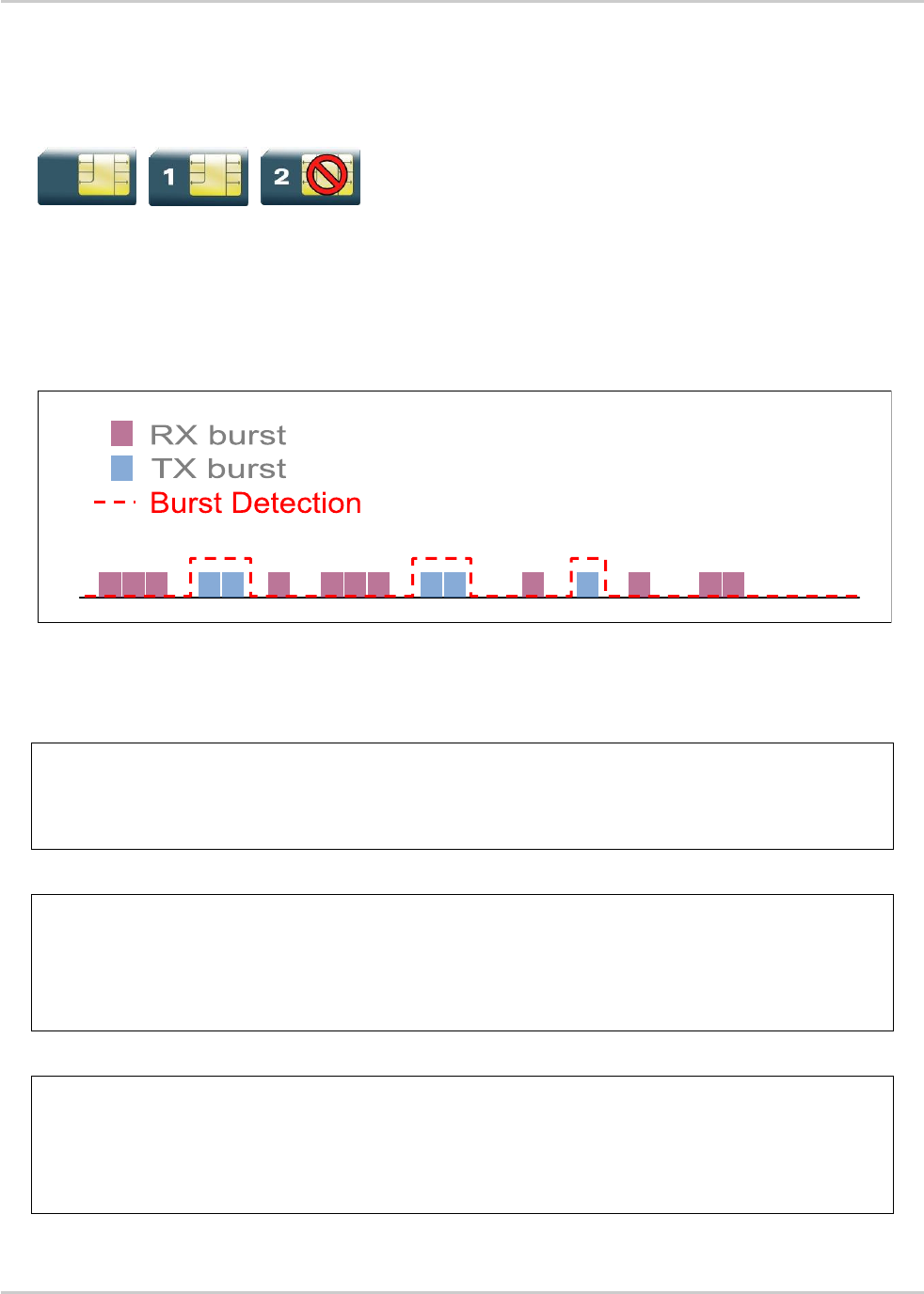
AT Commands Interface Guide for
Firmware 7.52
Error! Use the Home tab to apply Titre 1 to the text that you want to
appear here.
Error! Use the Home tab to apply Titre 2 to the text that you want to
appear here.
Rev. 1.0 Volume 2 March 7, 2014 172
14.19. GSM/GPRS Tx Burst Indication +WTBI
14.19.1. Description
This Sierra Wireless proprietary command allows enable/disable GSM/GPRS Tx Burst Indication. This
is to use a GPIO pin toggle to inform customer application of coming GPRS Tx burst.
14.19.2. Syntax
Action command
AT+WTBI=<mode>
OK
Read command
AT+WTBI?
+WTBI:<mode>
OK
Test command
AT+WTBI=?
+WTBI: (list of supported <mode>s)
OK

AT Commands Interface Guide for
Firmware 7.52
Error! Use the Home tab to apply Titre 1 to the text that you want to
appear here.
Error! Use the Home tab to apply Titre 2 to the text that you want to
appear here.
Rev. 1.0 Volume 2 March 7, 2014 173
14.19.3. Parameters and Defined Values
<mode>:
enable/disable the Tx burst indication.
0
disable
Note: A reset is needed to take into account the deactivation
1
enable
Note: A reset is not needed to take into account the activation
14.19.4. Parameter Storage
None.
14.19.5. Examples
Command
Responses
AT+WTBI=?
+WTBI: (0,1)
OK
AT+WTBI?
+WTBI: 0
OK
AT+WTBI=1
Note: Enable the Tx Burst indication
OK
AT+WTBI?
+WTBI: 1
OK
AT+WTBI=2
+CME ERROR: 3
Note: Index out of range
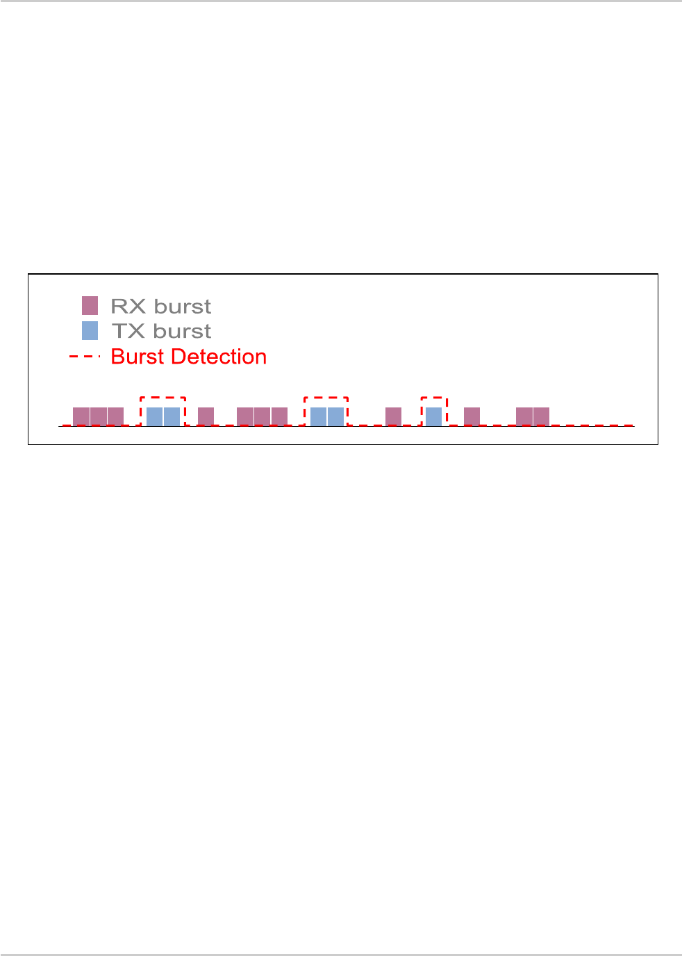
AT Commands Interface Guide for
Firmware 7.52
Error! Use the Home tab to apply Titre 1 to the text that you want to
appear here.
Error! Use the Home tab to apply Titre 2 to the text that you want to
appear here.
Rev. 1.0 Volume 2 March 7, 2014 174
14.19.6. Notes
14.19.6.1. Functional description
Burst Indication is provided by the mean of an output (GPIO) signal changing of state before and after
each GSM, GPRS or EDGE TX burst.
Before TX burst rising, a time anticipation is applied to Burst Indication GPIO state change. This
allows enough time for application to switch off peripherals properly.
After TX burst falling, a time delay is applied to Burst Indication GPIO state change. This ensures
current consumption peak required by GSM, GPRS or EDGE activity to be completely finished.
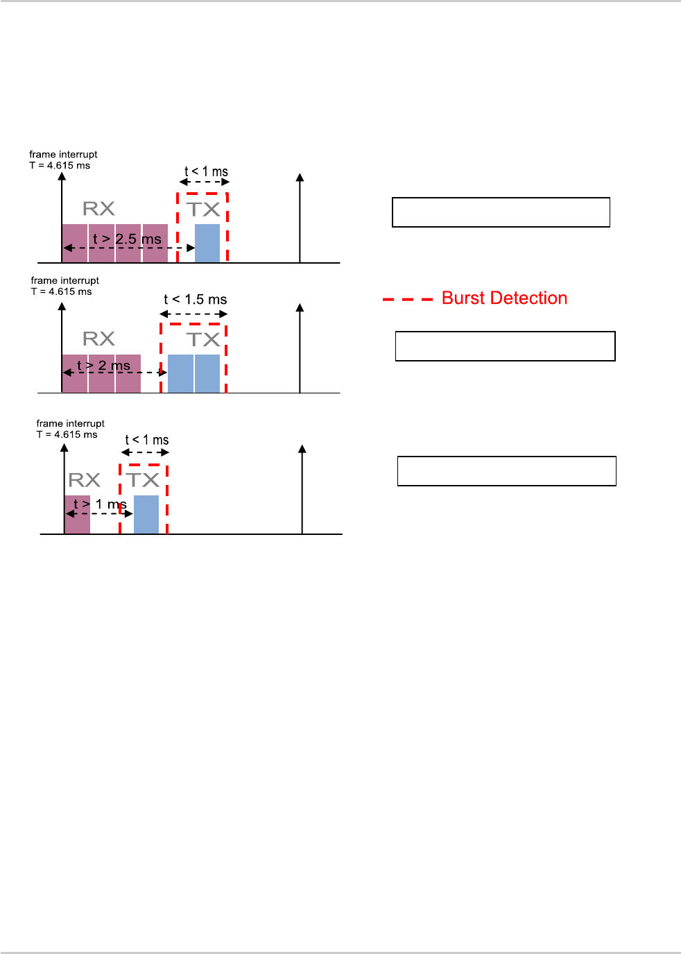
AT Commands Interface Guide for
Firmware 7.52
Error! Use the Home tab to apply Titre 1 to the text that you want to
appear here.
Error! Use the Home tab to apply Titre 2 to the text that you want to
appear here.
Rev. 1.0 Volume 2 March 7, 2014 175
14.19.6.2. Timing Overview
Time distribution of power supply between application peripherals and GSM, GPRS or EDGE
depends on network configuration and traffic. Typical cases and time ranges are derived from GSM
frame interrupt period (4.615 ms) and GPRS slot allocation, as shown hereafter.
GPRS class 8 (4RX/1TX)
GPRS class 6 (3RX/2TX)
(4RX/1TX)
GSM/ GPRS class 1(1RX/1TX)

AT Commands Interface Guide for
Firmware 7.52
Error! Use the Home tab to apply Titre 1 to the text that you want to
appear here.
Error! Use the Home tab to apply Titre 2 to the text that you want to
appear here.
Rev. 1.0 Volume 2 March 7, 2014 176
14.20. 3G Quality of Service Profile (Requested)
+CGEQREQ
14.20.1. Description
This command allows the TE to specify a UMTS Quality of Service Profile that is used when the MT
sends an Activate PDP Context Request message to the network.
The set command specifies a profile for the context identified by the (local) context identification
parameter, <cid>. The specified profile will be stored in the MT and sent to the network only at
activation or MS-initiated modification of the related context. Since this is the same parameter that is
used in the +CGDCONT and +CGDSCONT commands, the +CGEQREQ command is effectively an
extension to these commands. The QoS profile consists of a number of parameters, each of which
may be set to a separate value.
A special form of the set command, +CGEQREQ=<cid> causes the requested profile for context
number <cid> to become undefined.
The read command returns the current settings for each defined context.
The test command returns values supported as a compound value. If the MT supports several PDP
types, the parameter value ranges for each PDP type are returned on a separate line.
14.20.2. Syntax
Action command
AT+CGEQREQ=[<cid>[,<Traffic class>[,<Maximum bitrate UL>[,<Maximum bitrate
DL>[,<Guaranteed bitrate UL>[,<Guaranteed bitrate DL>[,<Delivery order>[,<Maximum
SDU size>[,<SDU error ratio>[,<Residual bit error ratio>[,<Delivery of erroneous
SDUs>[,<Transfer delay>[,<Traffic handling priority>[,<Source statistics
descriptor>[,<Signalling indication>]]]]]]]]]]]]]]]
OK

AT Commands Interface Guide for
Firmware 7.52
Error! Use the Home tab to apply Titre 1 to the text that you want to
appear here.
Error! Use the Home tab to apply Titre 2 to the text that you want to
appear here.
Rev. 1.0 Volume 2 March 7, 2014 177
Read command
AT+CGEQREQ?
+CGEQREQ: <cid>,<Traffic class>,<Maximum bitrate UL>,<Maximum bitrate
DL>,<Guaranteed bitrate UL>,<Guaranteed bitrate DL>,<Delivery order>,<Maximum SDU
size>,<SDU error ratio>,<Residual bit error ratio> ,<Delivery of erroneous
SDUs>,<Transfer delay>,<Traffic handling priority>,<Source statistics
descriptor>,<Signalling indication>
[<CR><LF>+CGEQREQ: <cid>,<Traffic class>,<Maximum bitrate UL>,<Maximum bitrate
DL>,<Guaranteed bitrate UL>,<Guaranteed bitrate DL>,<Delivery order>,<Maximum SDU
size>,<SDU error ratio>,<Residual bit error ratio>,<Delivery of erroneous
SDUs>,<Transfer delay>,<Traffic handling priority>,<Source statistics
descriptor>,<Signalling indication>[…]]
OK
Test command
AT+CGEQREQ=?
+CGEQREQ: <PDP_type>,(list of supported <Traffic class>s),(list of supported
<Maximum bitrate UL>s),(list of supported <Maximum bitrate DL>s),(list of supported
<Guaranteed bitrate UL>s),(list of supported <Guaranteed bitrate DL>s),(list of
supported <Delivery order>s),(list of supported <Maximum SDU size>s),(list of
supported <SDU error ratio>s) ,(list of supported <Residual bit error
ratio>s),(list of supported <Delivery of erroneous SDUs>s),(list of supported
<Transfer delay>s),(list of supported <Traffic handling priority>s) ,(list of
supported <Source statistics descriptor>s) ,(list of supported <Signalling
indication>s)
[<CR><LF>+CGEQREQ: <PDP_type>,(list of supported <Traffic class>s) ,(list of
supported <Maximum bitrate UL>s),(list of supported <Maximum bitrate DL>s),(list of
supported <Guaranteed bitrate UL>s),(list of supported <Guaranteed bitrate
DL>s),(list of supported <Delivery order>s),(list of supported <Maximum SDU
size>s),(list of supported <SDU error ratio>s),(list of supported <Residual bit
error ratio>s),(list of supported <Delivery of erroneous SDUs>s),(list of supported
<Transfer delay>s),(list of supported <Traffic handling priority>s) ,(list of
supported <Source statistics descriptor>s) ,(list of supported <Signalling
indication>s)[…]]
OK

AT Commands Interface Guide for
Firmware 7.52
Error! Use the Home tab to apply Titre 1 to the text that you want to
appear here.
Error! Use the Home tab to apply Titre 2 to the text that you want to
appear here.
Rev. 1.0 Volume 2 March 7, 2014 178
14.20.3. Parameters and Defined Values
<cid>:
a particular PDP context definition (see +CGDCONT and +CGDSCONT command)
integer type
<Traffic class>:
type of application for which the UMTS bearer service is optimised (please refer to Table
1: UMTS QoS classes)
integer type
0
conversational
1
streaming
2
interactive
3
background
4
subscribed value (default value)
<Maximum bitrate UL>:
maximum number of kbits/s delivered to UMTS (up-link traffic) at a SAP
integer type
if the parameter is set to "0", the subscribed value will be requested
this parameter should be provided if the Traffic class is specified as conversational or
streaming
0
subscribed maximum bit rate for uplink (default)
65535
0 kbps
1 – 63
in 1 kbps increment
64 – 568
in 8 kbps increments
576 - 8640
in 64 kbps increments
<Maximum bitrate DL>:
maximum number of kbits/s delivered by UMTS (down-link traffic) at a SAP
integer type
if the parameter is set to "0", the subscribed value will be requested
this parameter should be provided if the Traffic class is specified as conversational or
streaming
0
subscribed maximum bit rate for downlink (default value)
65535
0 kbps
1 – 63
in 1 kbps increment
64 – 568
in 8 kbps increments
576 - 8640
in 64 kbps increments

AT Commands Interface Guide for
Firmware 7.52
Error! Use the Home tab to apply Titre 1 to the text that you want to
appear here.
Error! Use the Home tab to apply Titre 2 to the text that you want to
appear here.
Rev. 1.0 Volume 2 March 7, 2014 179
8640 – 16000
in 100 kbps increments
<Guaranteed bitrate UL>:
guaranteed number of kbits/s delivered to UMTS (up-link traffic) at a SAP (provided that
there is data to deliver)
integer type
if the parameter is set to '"0", the subscribed value will be requested
this parameter should be provided if the Traffic class is specified as conversational or
streaming
Note: The Guaranteed bit rate for uplink value is ignored if the Traffic Class is
Interactive class or Background class, or Maximum bit rate for uplink is set to 0
kbps.
0
subscribed maximum bit rate for uplink (default value)
65535
0 kbps
1 – 63
in 1 kbps increment
64 – 568
in 8 kbps increments
576 - 8640
in 64 kbps increments
<Guaranteed bitrate DL>:
guaranteed number of kbits/s delivered by UMTS (down-link traffic) at a SAP (provided
that there is data to deliver)
integer type
if the parameter is set to "0", the subscribed value will be requested
this parameter should be provided if the Traffic class is specified as conversational or
streaming
Note: The Guaranteed bit rate for downlink value is ignored if the Traffic Class is
Interactive class or Background class, or Maximum bit rate for downlink is set
to 0 kbps.
0
subscribed maximum bit rate for downlink (default value)
65535
0 kbps
1 – 63
in 1 kbps increment
64 – 568
in 8 kbps increments
576 – 8640
in 64 kbps increments
8640 - 16000
in 100 kbps increments
<Delivery order>:
indicates whether the UMTS bearer shall provide in-sequence SDU delivery or not
integer type
0
no
1
yes
2
subscribed value (default value)

AT Commands Interface Guide for
Firmware 7.52
Error! Use the Home tab to apply Titre 1 to the text that you want to
appear here.
Error! Use the Home tab to apply Titre 2 to the text that you want to
appear here.
Rev. 1.0 Volume 2 March 7, 2014 180
<Maximum SDU size>:
maximum allowed SDU size in octets
integer type
if the parameter is set to "0", the subscribed value will be requested
0
subscribed maximum SDU size (default value)
10 – 1500
in 10 octets increments
1502
1510
1520
<SDU error ratio>:
target value for the fraction of SDUs lost or detected as erroneous. SDU error ratio is
defined only for conforming traffic. The value is specified as "mEe".
string type
Example: a target SDU error ratio of 1•10-3 would be specified as '1E3' (e.g.
AT+CGEQREQ=…,"1E3",…)
"0E0"
0, subscribed SDU error ratio (default value)
"1E2"
1•10-2
"7E3"
7•10-3
"1E3"
1•10-3
"1E4"
1•10-4
"1E5"
1•10-5
"1E6"
1•10-6
<Residual bit error ratio>:
target value for the undetected bit error ratio in the delivered SDUs. If no error detection is
requested, Residual bit error ratio indicates the bit error ratio in the delivered SDUs. The
value is specified as 'mEe'.
string type
Example: a target residual bit error ratio of 5•10-3 would be specified as '5E3' (e.g.
AT+CGEQREQ=…,"5E3",…)
"0E0"
0, subscribed residual BER (default value)
"5E2"
5•10-2
"1E2"
1•10-2
"5E3"
5•10-3
"4E3"
4•10-3
"1E3"
1•10-3
"1E4"
1•10-4

AT Commands Interface Guide for
Firmware 7.52
Error! Use the Home tab to apply Titre 1 to the text that you want to
appear here.
Error! Use the Home tab to apply Titre 2 to the text that you want to
appear here.
Rev. 1.0 Volume 2 March 7, 2014 181
"1E5"
1•10-5
"1E6"
1•10-6
"6E8"
6•10-8
<Delivery of erroneous
SDUs>:
indicates whether SDUs detected as erroneous shall be delivered or not
integer type
0
no
1
yes
2
no detect
3
subscribed value (default value)
<Transfer delay>:
targeted time between request to transfer an SDU at one SAP to its delivery at the other
SAP, in milliseconds
integer type
Note: The transfer delay value is ignored, if the Traffic Class is Interactive class or
Background class.
0
subscribed transfer delay (default value)
10 – 150
in 10 ms increments
200 – 950
in 50 kbps increments
1000 – 4000
in 100 ms increments
<Traffic handling
priority>:
relative importance for handling of all SDUs belonging to the UMTS bearer compared to
the SDUs of other bearers
integer type
Note: The transfer delay value is ignored if the Traffic Class is Conversation,
Streaming class or Background class.
0
subscribed transfer delay (default value)
1
priority level 1
2
priority level 2
3
priority level 3
<Source statistics
descriptor>:
characteristics of the source of the submitted SDUs for a PDP context
integer type
this parameter should be provided if the Traffic Class is specified as conversation or
streaming
this parameter is ignored if the Traffic Class is Interactive class or Background class
0
characteristics of SDUs is unknown (default value)

AT Commands Interface Guide for
Firmware 7.52
Error! Use the Home tab to apply Titre 1 to the text that you want to
appear here.
Error! Use the Home tab to apply Titre 2 to the text that you want to
appear here.
Rev. 1.0 Volume 2 March 7, 2014 182
1
characteristics of SDUs corresponds to a speech source
<Signalling Indication>:
signaling content of submitted SDUs for a PDP context
integer type
this parameter should be provided if the Traffic Class is specified as interactive
this parameter is ignored if the Traffic Class is Conversational class, Streaming class
or Background class
0
PDP context is not optimized for signalling (default value)
1
PDP context is optimized for signalling <PDP_type>: (see +CGDCONT command)
<PDP type>
(Packet Data Protocol type) a string parameter which specifies the type of packet data
protocol
"IP"
internet protocol
"PP"
point to point protocol
14.20.4. Parameter Storage
The parameters are stored in EEPROM without using AT&W command. Default values can be
restored using AT&F.
14.20.5. Examples
Command
Responses
AT+CGEQREQ=?
Note: Test command
+CGEQREQ: "IP",(0-4),(0-8640,65535),(0-
16000,65535),(0-8640,65535),(0-
16000,65535),(0-2),(0,10-
1500,1502,1510,1520),("0E0","1E1","1E2","7E3
","1E3","1E4","1E5","1E6"),("0E0","5E2","1E2
","5E3","4E3","1E3","1E4","1E5","1E6","6E8")
,(0-3),(0,10-4000),(0-3),(0-1),(0-1)
+CGEQREQ: "PPP",(0-4),(0-8640,65535),(0-
16000,65535),(0-8640,65535),(0-
16000,65535),(0-2),(0,10-
1500,1502,1510,1520),("0E0","1E1","1E2","7E3
","1E3","1E4","1E5","1E6"),("0E0","5E2","1E2
","5E3","4E3","1E3","1E4","1E5","1E6","6E8")
,(0-3),(0,10-4000),(0-3),(0-1),(0-1)
OK
AT+CGDCONT=1,"IP","internet";
+CGDCONT=2,"IP","abc.com"
OK

AT Commands Interface Guide for
Firmware 7.52
Error! Use the Home tab to apply Titre 1 to the text that you want to
appear here.
Error! Use the Home tab to apply Titre 2 to the text that you want to
appear here.
Rev. 1.0 Volume 2 March 7, 2014 183
Command
Responses
AT+CGEQREQ?
Note: Read command
+CGEQREQ:
1,4,0,0,0,0,2,0,"0E0","0E0",3,0,0,0,0
+CGEQREQ:
2,4,0,0,0,0,2,0,"0E0","0E0",3,0,0,0,0
OK
AT+CGEQREQ=1,3,0,128,0,0,2,1500,"0E0",
"0E0",3,0,0,0,0
Note: Specifies a 3G QoS profile for PDP context #1
OK
AT+CGEQREQ?
Note: Read command
+CGEQREQ:
1,3,0,128,0,0,2,1500,"0E0","0E0",3,0,0,0,0
+CGEQREQ:
2,4,0,0,0,0,2,0,"0E0","0E0",3,0,0,0,0
OK
AT+CGEQREQ=1
Note: Undefined 3G QoS profile for PDP context #1
OK
AT+CGEQREQ?
Note: Undefined 3G QoS profile for PDP context #1
+CGEQREQ:
1,4,0,0,0,0,2,0,"0E0","0E0",3,0,0,0,0
+CGEQREQ:
2,4,0,0,0,0,2,0,"0E0","0E0",3,0,0,0,0
OK
AT+CGEQREQ=3,3,32,0,0,0,2,0,"0E0","0E0
",3,0,0
Note: Specifies a 3G QoS profile for PDP context #3 which
is not defined yet
+CME ERROR: 3
14.20.6. Notes
Traffic class
Conversational
class
conversational
RT
Streaming class
streaming RT
Interactive class
Interactive best
effort
Background
Background best
effort
Fundamental
characteristics
Preserve time
relation (variation)
between information
entities of the
stream
Conversational
pattern (stringent
and low delay )
Preserve time
relation (variation)
between information
entities of the
stream
Request response
pattern
Preserve payload
content
Destination is not
expecting the data
within a certain time
Preserve payload
content

AT Commands Interface Guide for
Firmware 7.52
Error! Use the Home tab to apply Titre 1 to the text that you want to
appear here.
Error! Use the Home tab to apply Titre 2 to the text that you want to
appear here.
Rev. 1.0 Volume 2 March 7, 2014 184
Traffic class
Conversational
class
conversational
RT
Streaming class
streaming RT
Interactive class
Interactive best
effort
Background
Background best
effort
Example of the
application
voice
streaming video
Web browsing
background
download of emails
Table 5: UMTS QoS classes

AT Commands Interface Guide for
Firmware 7.52
Error! Use the Home tab to apply Titre 1 to the text that you want to
appear here.
Error! Use the Home tab to apply Titre 2 to the text that you want to
appear here.
Rev. 1.0 Volume 2 March 7, 2014 185
14.21. 3G Quality of Service Profile (Minimum
acceptable) +CGEQMIN
14.21.1. Description
This command allows the TE to specify a minimum acceptable profile, which is checked by the MT
against the negotiated profile returned in the Activate/Modify PDP Context Accept message.
The set command specifies a profile for the context identified by the (local) context identification
parameter, <cid>. The specified profile will be stored in the MT and checked against the negotiated
profile only at activation or MS-initiated modification of the related context. Since this is the same
parameter that is used in the +CGDCONT and +CGDSCONT commands, the +CGEQMIN command
is effectively an extension to these commands. The QoS profile consists of a number of parameters,
each of which may be set to a separate value.
A special form of the set command, +CGEQMIN= <cid> causes the minimum acceptable profile for
context number <cid> to become undefined. In this case, no check is made against the negotiated
profile.
The read command returns the current settings for each defined context.
The test command returns values supported as a compound value. If the MT supports several PDP
types, the parameter value ranges for each PDP type are returned on a separate line.
14.21.2. Syntax
Action command
AT+CGEQMIN=[<cid>[,<Traffic class>[,<Maximum bitrate UL>[,<Maximum bitrate
DL>[,<Guaranteed bitrate UL>[,<Guaranteed bitrate DL>[,<Delivery order>[,<Maximum
SDU size>[,<SDU error ratio>[,<Residual bit error ratio>[,<Delivery of erroneous
SDUs>[,<Transfer delay>[,<Traffic handling priority>[,<Source statistics
descriptor>[,<Signalling indication>]]]]]]]]]]]]]]]
OK

AT Commands Interface Guide for
Firmware 7.52
Error! Use the Home tab to apply Titre 1 to the text that you want to
appear here.
Error! Use the Home tab to apply Titre 2 to the text that you want to
appear here.
Rev. 1.0 Volume 2 March 7, 2014 186
Read command
AT+CGEQMIN?
+CGEQMIN: <cid>,<Traffic class>,<Maximum bitrate UL>,<Maximum bitrate
DL>,<Guaranteed bitrate UL>,<Guaranteed bitrate DL>,<Delivery order>,<Maximum SDU
size>,<SDU error ratio>,<Residual bit error ratio> ,<Delivery of erroneous
SDUs>,<Transfer delay>,<Traffic handling priority>,<Source statistics
descriptor>,<Signalling indication>
[<CR><LF>+CGEQMIN: <cid>,<Traffic class>,<Maximum bitrate UL>,<Maximum bitrate
DL>,<Guaranteed bitrate UL>,<Guaranteed bitrate DL>,<Delivery order>,<Maximum SDU
size>,<SDU error ratio>,<Residual bit error ratio>,<Delivery of erroneous
SDUs>,<Transfer delay>,<Traffic handling priority>,<Source statistics
descriptor>,<Signalling indication>[…]]
OK
Test command
AT+CGEQMIN=?
+CGEQMIN: <PDP_type>,(list of supported <Traffic class>s),(list of supported
<Maximum bitrate UL>s),(list of supported <Maximum bitrate DL>s),(list of supported
<Guaranteed bitrate UL>s),(list of supported <Guaranteed bitrate DL>s),(list of
supported <Delivery order>s),(list of supported <Maximum SDU size>s),(list of
supported <SDU error ratio>s) ,(list of supported <Residual bit error
ratio>s),(list of supported <Delivery of erroneous SDUs>s),(list of supported
<Transfer delay>s),(list of supported <Traffic handling priority>s) ,(list of
supported <Source statistics descriptor>s) ,(list of supported <Signalling
indication>s)
[<CR><LF>+CGEQMIN: <PDP_type>,(list of supported <Traffic class>s) ,(list of
supported <Maximum bitrate UL>s),(list of supported <Maximum bitrate DL>s),(list of
supported <Guaranteed bitrate UL>s),(list of supported <Guaranteed bitrate
DL>s),(list of supported <Delivery order>s),(list of supported <Maximum SDU
size>s),(list of supported <SDU error ratio>s),(list of supported <Residual bit
error ratio>s),(list of supported <Delivery of erroneous SDUs>s),(list of supported
<Transfer delay>s),(list of supported <Traffic handling priority>s) ,(list of
supported <Source statistics descriptor>s) ,(list of supported <Signalling
indication>s)[…]]
OK

AT Commands Interface Guide for
Firmware 7.52
Error! Use the Home tab to apply Titre 1 to the text that you want to
appear here.
Error! Use the Home tab to apply Titre 2 to the text that you want to
appear here.
Rev. 1.0 Volume 2 March 7, 2014 187
14.21.3. Parameters and Defined Values
<cid>:
a particular PDP context definition (see +CGDCONT and +CGDSCONT commands)
integer type
<Traffic class>:
type of application for which the UMTS bearer service is optimized. Please refer to Table 1:
UMTS QoS classes for more information on QoS classes
integer type
0
conversational
1
streaming
2
interactive
3
background
4
subscribed value (default value)
<Maximum bitrate
UL>:
maximum number of kbits/s delivered to UMTS (up-link traffic) at a SAP
integer type
if the parameter is set to "0", the subscribed value will be requested
this parameter should be provided if the Traffic class is specified as conversational or
streaming
0
subscribed maximum bit rate for uplink (default value)
65535
0 kbps
1 – 63
in 1 kbps increment
64 – 568
in 8 kbps increments
576 - 8640
in 64 kbps increments
<Maximum bitrate
DL>:
maximum number of kbits/s delivered by UMTS (down-link traffic) at a SAP
integer type
if the parameter is set to "0", the subscribed value will be requested
this parameter should be provided if the Traffic class is specified as conversational or
streaming
0
subscribed maximum bit rate for downlink (default value)
65535
0 kbps
1 – 63
in 1 kbps increment
64 – 568
in 8 kbps increments
576 - 8640
in 64 kbps increments

AT Commands Interface Guide for
Firmware 7.52
Error! Use the Home tab to apply Titre 1 to the text that you want to
appear here.
Error! Use the Home tab to apply Titre 2 to the text that you want to
appear here.
Rev. 1.0 Volume 2 March 7, 2014 188
8640 - 16000
in 100 kbps increments
<Guaranteed
bitrate UL>:
guaranteed number of kbits/s delivered to UMTS (up-link traffic) at a SAP (provided that
there is data to deliver)
integer type
if the parameter is set to '"0", the subscribed value will be requested
this parameter should be provided if the Traffic class is specified as conversational or
streaming.
Note: The Guaranteed bit rate for uplink value is ignored if the Traffic Class is
Interactive class or Background class, or Maximum bit rate for uplink is set to 0
kbps.
0
subscribed maximum bit rate for uplink (default value)
65535
0 kbps
1 – 63
in 1 kbps increment
64 – 568
in 8 kbps increments
576 - 8640
in 64 kbps increments
<Guaranteed
bitrate DL>:
guaranteed number of kbits/s delivered by UMTS (down-link traffic) at a SAP (provided that
there is data to deliver)
integer type
if the parameter is set to "0", the subscribed value will be requested
this parameter should be provided if the Traffic class is specified as conversational or
streaming.
Note: The Guaranteed bit rate for downlink value is ignored if the Traffic Class is
Interactive class or Background class, or Maximum bit rate for downlink is set to
0 kbps.
0
subscribed maximum bit rate for downlink (default value)
65535
0 kbps
1 – 63
in 1 kbps increment
64 – 568
in 8 kbps increments
576 – 8640
in 64 kbps increments
8640 - 16000
in 100 kbps increments
<Delivery order>:
indicates whether the UMTS bearer shall provide in-sequence SDU delivery or not
integer type
0
no
1
yes
2
subscribed value (default value)

AT Commands Interface Guide for
Firmware 7.52
Error! Use the Home tab to apply Titre 1 to the text that you want to
appear here.
Error! Use the Home tab to apply Titre 2 to the text that you want to
appear here.
Rev. 1.0 Volume 2 March 7, 2014 189
<Maximum SDU size>:
maximum allowed SDU size in octets
integer type
if the parameter is set to "0", the subscribed value will be requested
0
subscribed maximum SDU size (default value)
10 – 1500
in 10 octets increments
1502
1510
1520
<SDU error ratio>:
target value for the fraction of SDUs lost or detected as erroneous. SDU error ratio is
defined only for conforming traffic. The value is specified as "mEe".
string type
Example: a target SDU error ratio of 1•10-3 would be specified as "1E3" (e.g.
AT+CGEQMIN=…,"1E3",…). "0E0" means subscribed value.
"0E0"
0, subscribed SDU error ratio (default value)
"1E2"
1•10-2
"7E3"
7•10-3
"1E3"
1•10-3
"1E4"
1•10-4
"1E5"
1•10-5
"1E6"
1•10-6
<Residual bit error
ratio>:
target value for the undetected bit error ratio in the delivered SDUs. If no error
detection is requested, Residual bit error ratio indicates the bit error ratio in the
delivered SDUs. The value is specified as 'mEe'.
string type
Example: a target residual bit error ratio of 5•10-3 would be specified as "5E3" (e.g.
AT+CGEQMIN=…,"5E3",…)
"0E0"
0, subscribed residual BER (default value)
"5E2"
5•10-2
"1E2"
1•10-2
"5E3"
5•10-3
"4E3"
4•10-3
"1E3"
1•10-3
"1E4"
1•10-4

AT Commands Interface Guide for
Firmware 7.52
Error! Use the Home tab to apply Titre 1 to the text that you want to
appear here.
Error! Use the Home tab to apply Titre 2 to the text that you want to
appear here.
Rev. 1.0 Volume 2 March 7, 2014 190
"1E5"
1•10-5
"1E6"
1•10-6
"6E8"
6•10-8
<Delivery of erroneous
SDUs>:
indicates whether SDUs detected as erroneous shall be delivered or not
integer type
0
no
1
yes
2
no detect
3
subscribed value (default value)
<Transfer delay>:
targeted time between request to transfer an SDU at one SAP to its delivery at the
other SAP, in milliseconds
integer type
Note: The transfer delay value is ignored, if the Traffic Class is Interactive class
or Background class.
0
subscribed transfer delay (default value)
10 – 150
in 10 ms increments
200 – 950
in 50 ms increments
1000 – 4000
in 100 ms increments
<Traffic handling
priority>:
relative importance for handling of all SDUs belonging to the UMTS bearer
compared to the SDUs of other bearers
integer type
Note: The Traffic handling priority value is ignored, if the Traffic Class is
Conversation, Streaming class or Background class
0
subscribed traffic delay (default value)
1
priority level 1
2
priority level 2
3
priority level 3

AT Commands Interface Guide for
Firmware 7.52
Error! Use the Home tab to apply Titre 1 to the text that you want to
appear here.
Error! Use the Home tab to apply Titre 2 to the text that you want to
appear here.
Rev. 1.0 Volume 2 March 7, 2014 191
<Source statistics
descriptor>
characteristics of the source of the submitted SDUs for a PDP context
integer type
this parameter should be provided if the Traffic Class is specified as
conversation or streaming
this parameter is ignored if the Traffic Class is Interactive class or Background
class
0
characteristics of SDUs is unknown (default value)
1
characteristics of SDUs corresponds to a speech source
<Signalling indication>:
signaling content of submitted SDUs for a PDP context
integer type
this parameter should be provided if the Traffic Class is specified as interactive
this parameter is ignored if the Traffic Class is Conversational class, Streaming
class or Background class
0
PDP context is not optimized for signalling (default value)
1
PDP context is optimized for signalling <PDP_type>: (see +CGDCONT
command)
<PDP type>
(Packet Data Protocol type) a string parameter which specifies the type of
packet data protocol
"IP"
internet protocol
"PP"
point to point protocol
14.21.4. Parameter Storage
The parameters are stored in EEPROM without using AT&W command. Default values can be
restored using AT&F.

AT Commands Interface Guide for
Firmware 7.52
Error! Use the Home tab to apply Titre 1 to the text that you want to
appear here.
Error! Use the Home tab to apply Titre 2 to the text that you want to
appear here.
Rev. 1.0 Volume 2 March 7, 2014 192
14.21.5. Examples
Command
Responses
AT+CGEQMIN=?
Note: Test command
+CGEQMIN: "IP",(0-4),(0-8640,65535),(0-
16000,65535),(0-8640,65535),(0-16000,65535),(0-
2),(0,10-
1500,1502,1510,1520),("0E0","1E1","1E2","7E3","
1E3","1E4","1E5","1E6"),("0E0","5E2","1E2","5E3
","4E3","1E3","1E4","1E5","1E6","6E8"),(0-
3),(0,10-4000),(0-3),(0-1),(0-1)
+CGEQMIN: "PPP",(0-4),(0-8640,65535),(0-
16000,65535),(0-8640,65535),(0-16000,65535),(0-
2),(0,10-
1500,1502,1510,1520),("0E0","1E1","1E2","7E3","
1E3","1E4","1E5","1E6"),("0E0","5E2","1E2","5E3
","4E3","1E3","1E4","1E5","1E6","6E8"),(0-
3),(0,10-4000),(0-3),(0-1),(0-1)
OK
AT+CGDCONT=1,"IP","internet";+CGDCONT
=2,"IP","abc.com"
OK
AT+CGEQMIN?
Note: Read command
+CGEQMIN: 1,4,0,0,0,0,2,0,"0E0","0E0",3,0,0,0,0
+CGEQMIN: 2,4,0,0,0,0,2,0,"0E0","0E0",3,0,0,0,0
OK
AT+CGEQMIN=1,3,32,0,0,0,2,0,"0E0","0E
0",3,0,0,0,0
Note: Set the minimum 3G QoS for Cid=1, Traffic class =
background, Maximum bitrate UL = 32kbit/s, and all
other parameters set to subscribed value
OK
AT+CGEQMIN?
Note: Read command
+CGEQMIN:
1,3,32,0,0,0,2,0,"0E0","0E0",3,0,0,0,0
+CGEQMIN: 2,4,0,0,0,0,2,0,"0E0","0E0",3,0,0,0,0
OK
AT+CGEQMIN=1
Note: Undefined 3G QoS profile (minimum acceptable)
for PDP context #1
OK
AT+CGEQMIN?
Note: Read command
+CGEQMIN: 1,4,0,0,0,0,2,0,"0E0","0E0",3,0,0,0,0
+CGEQMIN: 2,4,0,0,0,0,2,0,"0E0","0E0",3,0,0,0,0
OK
AT+CGEQMIN=3,3,32,0,0,0,2,0,"0E0","0E
0",3,0,0,0,0
Note: Specifies a 3G QoS profile (minimum acceptable)
for PDP context #3 which is not defined yet
+CME ERROR: 3

AT Commands Interface Guide for
Firmware 7.52
Error! Use the Home tab to apply Titre 1 to the text that you want to
appear here.
Error! Use the Home tab to apply Titre 2 to the text that you want to
appear here.
Rev. 1.0 Volume 2 March 7, 2014 193
14.22. 3G Quality of Service Profile (Negotiated)
+CGEQNEG
14.22.1. Description
This command allows the TE to retrieve the negotiated QoS profiles returned in the Activate PDP
Context Accept message.
The execution command returns the negotiated QoS profile for the specified context identifiers,
<cid>s. The QoS profile consists of a number of parameters, each of which may have a separate
value.
The test command returns a list of <cid>s associated with active contexts.
14.22.2. Syntax
Action command
AT+CGEQNEG=[<cid>[,<cid>[,…]]]
+CGEQNEG: <cid>,<Traffic class>,<Maximum bitrate UL>,<Maximum bitrate
DL>,<Guaranteed bitrate UL>,<Guaranteed bitrate DL>,<Delivery order>,<Maximum SDU
size>,<SDU error ratio>,<Residual bit error ratio> ,<Delivery of erroneous
SDUs>,<Transfer delay>,<Traffic handling priority>
[<CR><LF>+CGEQNEG: <cid>,<Traffic class>,<Maximum bitrate UL>,<Maximum bitrate
DL>,<Guaranteed bitrate UL>,<Guaranteed bitrate DL>,<Delivery order>,<Maximum SDU
size>,<SDU error ratio>,<Residual bit error ratio>,<Delivery of erroneous
SDUs>,<Transfer delay>,<Traffic handling priority>[…]]
OK
Read command
None
Test command
AT+CGEQNEG=?
+CGEQNEG: (list of <cid>s associated with active contexts)
OK

AT Commands Interface Guide for
Firmware 7.52
Error! Use the Home tab to apply Titre 1 to the text that you want to
appear here.
Error! Use the Home tab to apply Titre 2 to the text that you want to
appear here.
Rev. 1.0 Volume 2 March 7, 2014 194
14.22.3. Parameters and Defined Values
<cid>:
a particular PDP context definition (see +CGDCONT and +CGDSCONT commands)
integer type
<Traffic class>:
type of application for which the UMTS bearer service is optimised. Please refer to Table 1:
UMTS QoS classes for more information on QoS classes
integer type
0
conversational
1
streaming
2
interactive
3
background
<Maximum bitrate
UL>:
maximum number of kbits/s delivered to UMTS (up-link traffic) at a SAP
integer type
range: 0 to 8640 kbps
<Maximum bitrate
DL>:
maximum number of kbits/s delivered by UMTS (down-link traffic) at a SAP
integer type
range: 0 to 16000 kbps
<Guaranteed
bitrate UL>:
guaranteed number of kbits/s delivered to UMTS (up-link traffic) at a SAP (provided that
there is data to deliver)
integer type
range: 0 to 8640 kbps
<Guaranteed
bitrate DL>:
guaranteed number of kbits/s delivered by UMTS (down-link traffic) at a SAP (provided that
there is data to deliver)
integer type
range: 0 to 16000 kbps
<Delivery order>:
parameter indicates whether the UMTS bearer shall provide in-sequence SDU delivery or
not
integer type
0
no
1
yes
<Maximum SDU size>:
maximum allowed SDU size in octets
integer type

AT Commands Interface Guide for
Firmware 7.52
Error! Use the Home tab to apply Titre 1 to the text that you want to
appear here.
Error! Use the Home tab to apply Titre 2 to the text that you want to
appear here.
Rev. 1.0 Volume 2 March 7, 2014 195
<SDU error ratio>:
target value for the fraction of SDUs lost or detected as erroneous. SDU error ratio is
defined only for conforming traffic. The value is specified as "mEe".
string type
Example: a target SDU error ratio of 1•10-3 would be specified as '1E3' (e.g.
AT+CGEQNEG=…,"1E3"…).
"0E0"
0, subscribed SDU error ratio (default value)
"1E2"
1•10-2
"7E3"
7•10-3
"1E3"
1•10-3
"1E4"
1•10-4
"1E5"
1•10-5
"1E6"
1•10-6
<Residual bit error
ratio>:
target value for the undetected bit error ratio in the delivered SDUs. If no error
detection is requested, Residual bit error ratio indicates the bit error ratio in the
delivered SDUs. The value is specified as 'mEe'.
string type
Example: a target residual bit error ratio of 5•10-3 would be specified as '5E3' (e.g.
AT+CGEQNEG=…,"5E3"…).
"0E0"
0, subscribed residual BER (default value)
"5E2"
5•10-2
"1E2"
1•10-2
"5E3"
5•10-3
"4E3"
4•10-3
"1E3"
1•10-3
"1E4"
1•10-4
"1E5"
1•10-5
"1E6"
1•10-6
"6E8"
6•10-8

AT Commands Interface Guide for
Firmware 7.52
Error! Use the Home tab to apply Titre 1 to the text that you want to
appear here.
Error! Use the Home tab to apply Titre 2 to the text that you want to
appear here.
Rev. 1.0 Volume 2 March 7, 2014 196
<Delivery of erroneous
SDUs>:
parameter indicates whether SDUs detected as erroneous shall be delivered or not
integer type
0
no
1
yes
2
no detect
<Transfer delay>:
targeted time between request to transfer an SDU at one SAP to its delivery at the
other SAP, in milliseconds
integer type
range: 10 – 4000 ms
<traffic handling
priority>:
relative importance for handling of all SDUs belonging to the UMTS bearer
compared to the SDUs of other bearers
integer type
1
priority level 1
2
priority level 2
3
priority level 3
14.22.4. Parameter Storage
None.

AT Commands Interface Guide for
Firmware 7.52
Error! Use the Home tab to apply Titre 1 to the text that you want to
appear here.
Error! Use the Home tab to apply Titre 2 to the text that you want to
appear here.
Rev. 1.0 Volume 2 March 7, 2014 197
14.22.5. Examples
Command
Responses
AT+CGEQNEG=?
Note: Test command
+CGEQNEG: "IP",(0-4),(0-8640,65535),(0-
16000,65535),(0-8640,65535),(0-
16000,65535),(0-2),(0,10-
1500,1502,1510,1520),("0E0","1E1","1E2","7E3",
"1E3","1E4","1E5","1E6"),("0E0","5E2","1E2","5
E3","4E3","1E3","1E4","1E5","1E6","6E8"),(0-
3),(0,10-4000),(0-3),(0-1),(0-1)
+CGEQMIN: "PPP",(0-4),(0-8640,65535),(0-
16000,65535),(0-8640,65535),(0-
16000,65535),(0-2),(0,10-
1500,1502,1510,1520),("0E0","1E1","1E2","7E3",
"1E3","1E4","1E5","1E6"),("0E0","5E2","1E2","5
E3","4E3","1E3","1E4","1E5","1E6","6E8"),(0-
3),(0,10-4000),(0-3),(0-1),(0-1)
OK
AT+CGDCONT=1,"IP","internet";
+CGDCONT=2,"IP","abc.com"
OK
AT+CGEQMIN?
Note: Read command
+CGEQMIN:
1,4,0,0,0,0,2,0,"0E0","0E0",3,0,0,0,0
+CGEQMIN:
2,4,0,0,0,0,2,0,"0E0","0E0",3,0,0,0,0
OK
AT+CGEQMIN=1,3,32,0,0,0,2,0,"0E0",
"0E0",3,0,0,0,0
Note: Set the minimum 3G QoS for Cid=1, Traffic
class = background, Maximum bitrate UL = 32kbit/s,
and all other parameters set to subscribed value
OK
AT+CGEQMIN?
Note: Read command
+CGEQMIN:
1,3,32,0,0,0,2,0,"0E0","0E0",3,0,0,0,0
+CGEQMIN:
2,4,0,0,0,0,2,0,"0E0","0E0",3,0,0,0,0
OK
AT+CGEQMIN=1
Note: Undefined 3G QoS profile (minimum
acceptable) for PDP context #1
OK

AT Commands Interface Guide for
Firmware 7.52
Error! Use the Home tab to apply Titre 1 to the text that you want to
appear here.
Error! Use the Home tab to apply Titre 2 to the text that you want to
appear here.
Rev. 1.0 Volume 2 March 7, 2014 198
Command
Responses
AT+CGEQMIN?
Note: Read command
+CGEQMIN:
1,4,0,0,0,0,2,0,"0E0","0E0",3,0,0,0,0
+CGEQMIN:
2,4,0,0,0,0,2,0,"0E0","0E0",3,0,0,0,0
OK
AT+CGEQMIN=3,3,32,0,0,0,2,0,"0E0",
"0E0",3,0,0,0,0
Note: Specifies a 3G QoS profile (minimum
acceptable) for PDP context #3 which is not defined
yet
+CME ERROR: 3

AT Commands Interface Guide for
Firmware 7.52
Error! Use the Home tab to apply Titre 1 to the text that you want to
appear here.
Error! Use the Home tab to apply Titre 2 to the text that you want to
appear here.
Rev. 1.0 Volume 2 March 7, 2014 199
14.23. Authentication Protocol AT+WPPP
14.23.1. Description
This command will set the authentication protocol. Three options are possible:
No protocol: No user name and password is used. The PPP connection is established
without authentication.
PAP Protocol: This is a simple authentication protocol used to authenticate a user before the
network access. The user name and password are sent in plain text for the authentication.
CHAP protocol: This protocol periodically verifies the identity of the client by using a three-
way handshake. This happens when the link is established, and may happen again at any
time. The verification is based on a shared secret (such as the client user's and password).
The shared password is encrypted before it is sent.
PAP is the default authentication protocol.
14.23.2. Syntax
Action command
AT+WPPP=<auth>,[<cid>],[<username],[<password>]
OK
Read command
AT+WPPP?
+WPPP: <auth>,[<cid>],[<username>],[<password>]
OK
Test command
AT+WPPP=?
+WPPP: <list of supported <auth>s>,[<list of supported <cid>s>]
OK

AT Commands Interface Guide for
Firmware 7.52
Error! Use the Home tab to apply Titre 1 to the text that you want to
appear here.
Error! Use the Home tab to apply Titre 2 to the text that you want to
appear here.
Rev. 1.0 Volume 2 March 7, 2014 200
14.23.3. Parameters and Defined Values
<auth>
types of authentication supported
0
none
1
PAP (default)
2
CHAP
<cid>:
PDP context identifier used in CGDCONT. If omitted, this configuration will be for all
PDP contexts.
range: 1-4
integer type
<username>:
username for CHAP or PAP
string type, maximum of 50 characters
If omitted, username will be retrieved either from PPP connection or the application.
<password>:
password for CHAP or PAP
string type, maximum of 50 characters
If omitted, password will be retrieved either from PPP connection or the application.
14.23.4. Parameter Storage
None.
14.23.5. Examples
Command
Responses
AT+WPPP=?
+WPPP: (0-2),(1-4)
OK
AT+WPPP=2
OK
AT+WPPP=2,1,"myusername","mypassword"
OK
Note: Configure PDP context Cid=1 with CHAP protocol and set
username and password.
AT+WPPP?
+WPPP: 2,1,"myusername","mypassword"
OK

Rev. 1.0 Volume 2 March 7, 2014 201
15. PLMN Commands
15.1. Selection of Preferred PLMN list +CPLS
15.1.1. Description
This command is used to select one PLMN selector with access technology listed in the SIM card or
active application in the UICC (GSM or USIM) that is used by +CPOL command.
15.1.2. Syntax
Action command
AT+CPLS=<list>
OK
Read command
AT+CPLS?
+CPLS: <list>
OK
Test command
AT+CPLS=?
+CPLS: (list of supported <list>s)
OK

AT Commands Interface Guide for
Firmware 7.52
Error! Use the Home tab to apply Titre 1 to the text that you want to
appear here.
Error! Use the Home tab to apply Titre 2 to the text that you want to
appear here.
Rev. 1.0 Volume 2 March 7, 2014 202
15.1.3. Parameters and Defined Values
<list>:
preferred PLMN list
0
user controlled PLMN selector with access technology EF_PLMNwAct
If this file is not found in the SIM/UICC, then PLMN preferred list EF_PLMNSel will
be selected. (this file is only available in SIM card or GSM apllication selected in
UICC).
1
operator controlled PLMN selector with access technology EF_OPLMNwAct
2
home PLMN selector with access technology EF_HPLMNwAct
15.1.4. Parameter Storage
None.
15.1.5. Examples
Command
Responses
AT+CPLS?
Note: Ask for selection of the SIM/UICC file
+CPLS: 1
OK
Note: EF_OPLMNwAct is selected
AT+CPLS=0
Note: Selection of EF_PLMNwAct
OK
Note: If EF_PLMNwAct is not present, EF_PLMNsel will be
selected
AT+CPLS=1
Note: Selection of EF_OPLMNwAct
+CME ERROR: 3
Note: EF_OPLMNwAct is not present
AT+CPLS=?
Note: Get possible values
+CPLS: (0,1,2)
OK
Note: The 3 files with Access technology are present and
can be selected
AT+CPLS=?
Note: Get possible values
+CPLS: (0)
OK
Note: Only EF_PLMNwAct or EF_PLMNsel can be selected

AT Commands Interface Guide for
Firmware 7.52
Error! Use the Home tab to apply Titre 1 to the text that you want to
appear here.
Error! Use the Home tab to apply Titre 2 to the text that you want to
appear here.
Rev. 1.0 Volume 2 March 7, 2014 203
15.1.6. Notes
PLMN Sel
PLMNwAct
OPLMNwAct
HPLMNwAct
<list> default
value
X
0
X
0
X
1
X
2
X
X
0
X
X
0
X
X
0
X
X
X
0
X
X
X
0
X
X
0
X
X
0
X
X
1
The <list> default value is linked to the SIM/UICC file allocation.
The priority is 0 > 1 > 2.

AT Commands Interface Guide for
Firmware 7.52
Error! Use the Home tab to apply Titre 1 to the text that you want to
appear here.
Error! Use the Home tab to apply Titre 2 to the text that you want to
appear here.
Rev. 1.0 Volume 2 March 7, 2014 204
15.2. Operator Selection +COPS
Or:
15.2.1. Description
There are three possible ways of selecting an operator (PLMN):
The product is in manual mode. It then tries to find the operator specified by the application
and if found, tries to register.
The product is in automatic mode. It then tries to find the home operator and if found, tries to
register. If not found, the product automatically searches for another network.
The product enters into manual/automatic mode. It tries to find an operator specified by the
application (as in manual mode). If this attempt fails it enters automatic mode. If this is
successful, the operator specified by the application is selected. The mobile equipment then
enters into automatic mode.
Note: The read command returns the current mode and the current selected operator. In manual mode, this
PLMN may not be the one set by the application (as it is in the search phase).
Note: The access technology selected paameter, <AcT>, should only be used in terminals capable of
registering to more than one access technology
Note: The access technology selected parameter, <AcT>, is not applicable in automatic mode (<mode>=0)
Note: These commands are not allowed during communication.
15.2.2. Syntax
Action command
AT+COPS=<mode>[,<format>[,<oper>[,<AcT>]]]
OK
Read command
AT+COPS?
+COPS: <mode>[,<format>,<oper>[,<AcT>]]
OK

AT Commands Interface Guide for
Firmware 7.52
Error! Use the Home tab to apply Titre 1 to the text that you want to
appear here.
Error! Use the Home tab to apply Titre 2 to the text that you want to
appear here.
Rev. 1.0 Volume 2 March 7, 2014 205
Test command
AT+COPS=?
+COPS: [list of supported (<stat>,long alphanumeric <oper>,short
alphanumeric <oper>,numeric <oper>[,<AcT>])s]
OK
15.2.3. Parameters and Defined Values
<mode>:
network registration mode
0
automatic (default value)
1
manual (<oper> shall be present and <AcT> field is optional)
2
deregistration; ME will be unregistered until <mode>=0 or 1 is selected
3
set only <format> (for read command AT+COPS?)
4
manual/automatic (<oper> shall be present), if manual selection fails, automatic
mode is entered.
127
Force to automatic mode at next power on (current mode stays unchanged until
power down)
<format>:
format of <oper> field
0
long alphanumeric format <oper>
1
short alphanumeric format <oper>
2
numeric <oper> (default value)
<stat>:
status of <oper> field
0
unknown
1
available
2
current
3
forbidden
<oper>:
operator identifier (MCC/MNC in numeric format only for operator selection)
The long alphanumeric format can be up to 16 characters long (for operator
names description see "Operator names" section in the present document
"Appendixes"; field is "Name"). The short alphanumeric format can be up to 10
characters long.
<AcT
access technology selected
0
GSM

AT Commands Interface Guide for
Firmware 7.52
Error! Use the Home tab to apply Titre 1 to the text that you want to
appear here.
Error! Use the Home tab to apply Titre 2 to the text that you want to
appear here.
Rev. 1.0 Volume 2 March 7, 2014 206
2
UTRAN
15.2.4. Parameter Storage
The <format> and <mode> parameters are stored in EEPROM using AT&W command. The default
values can be restored using AT&F.
Note: The AT+COPS parameter storage information is not applicable for mode 2.

AT Commands Interface Guide for
Firmware 7.52
Error! Use the Home tab to apply Titre 1 to the text that you want to
appear here.
Error! Use the Home tab to apply Titre 2 to the text that you want to
appear here.
Rev. 1.0 Volume 2 March 7, 2014 207
15.2.5. Examples
Command
Responses
AT+COPS?
Note: Ask for current PLMN
+COPS: 0,2,45400,2
OK
Note: Home PLMN is HK CSL with access technology UTRAN
AT+COPS=?
Note: Ask for PLMN list
+COPS: (3,"SmarToneVodafone","SMC-
Voda","45406",2), (0,"SUNDAY","SUNDAY",
"45419",2),(2,"HK CSL","CSL", "45400",2),(0,"3
HK","3","45403",2)
OK
Note: Home PLMN is CSL, SMC-Voda, Sunday and 3 networks have
been detected
AT+COPS=1,2,45400,2
Note: Ask for registration on HK CSL networks
+CME ERROR: 32
Note: Network not allowed – emergency calls only
AT+COPS=1,2,45406
Note: Ask for registration on SMC-Voda network
+CME ERROR: 529
Note: Selection failed – emergency calls only
AT+COPS=0
Note: Ask for registration in automatic mode
OK
Note: Successful
AT+COPS=3,0
Note: Set <format> to long alphanumeric
OK
Note: Successful
AT+COPS?
Note: Ask for current PLMN
+COPS: 0,0,"HK CSL",2
OK
Note: Home PLMN is HK CSL
AT+COPS=2
Note: Ask for deregistration from network
OK
Note: Successful
AT+COPS?
Note: Ask for current PLMN
+COPS: 2
OK
Note: ME is unregistered until <mode>=0 or 1 is selected

AT Commands Interface Guide for
Firmware 7.52
Error! Use the Home tab to apply Titre 1 to the text that you want to
appear here.
Error! Use the Home tab to apply Titre 2 to the text that you want to
appear here.
Rev. 1.0 Volume 2 March 7, 2014 208
15.2.6. Notes
If an incoming call occurs during a PLMN list request, the operation is aborted (+CME
ERROR: 520) and the unsolicited RING appears.
If SPN (Service Provider Name) is present in the SIM, it will be returned in both long and short
alphanumeric <oper> fields. The string in the "short" field will be the SPN truncated to the
appropriate number of characters (10).
The fact that the network supports emergency call (+CME ERROR: 547) does not imply that
emergency call without SIM is working. The only way to verify this state, is to do ATD112.
If the PLMN is unknown (meaning not present in the ROM table (see +COPN command), not
present in FLASH (see +WOLM command), and also not present in SIM (E-ONS, ONS...)),
the returned long name is formatted like "MCC XXX MNC YY(Y)" and the returned short
name is formatted like "XXX YY(Y)" where XXX is the MCC (3-digits) and YY(Y) is the MNC
(2-digits or 3-digits).

AT Commands Interface Guide for
Firmware 7.52
Error! Use the Home tab to apply Titre 1 to the text that you want to
appear here.
Error! Use the Home tab to apply Titre 2 to the text that you want to
appear here.
Rev. 1.0 Volume 2 March 7, 2014 209
15.3. Preferred Operator List +CPOL
15.3.1. Description
This command is used to edit (or update) the preferred list of networks located in SIM or active
application in the UICC (GSM or USIM).. This list is read in the SIM or active application in the UICC
(GSM or USIM) file selected by +CPLS command.
15.3.2. Syntax
Action command
AT+CPOL=[<index>][,<format>[,<oper>[,<GSM_AcT>,<GSMcomp_Act>,<Utran_Act>]]]
OK
Read command
AT+CPOL?
+CPOL: <index>,<format>,<oper>[,<GSM_AcT>,<GSMcomp_Act>,<Utran_Act>]
[+CPOL: <index>,<format>,<oper>[,<GSM_AcT>,<GSMcomp_Act>,<Utran_Act>][…]]
OK
Test command
AT+CPOL=?
+CPOL: (list of supported <index>s),(list of supported <format>s)
OK
15.3.3. Parameters and Defined Values
<format>:
format for <oper> parameter
0
long alphanumeric format for <oper>
1
short alphanumeric format for <oper>
2
numeric format for <oper>

AT Commands Interface Guide for
Firmware 7.52
Error! Use the Home tab to apply Titre 1 to the text that you want to
appear here.
Error! Use the Home tab to apply Titre 2 to the text that you want to
appear here.
Rev. 1.0 Volume 2 March 7, 2014 210
<oper>:
operator identifier
character string or integer (see <format>)
<GSM_AcT>:
GSM access technology
<GSMcomp_Act>:
GSM compact access technology
<Utran_Act>:
0
access technology not selected
1
access technology selected
15.3.4. Parameter Storage
None.
15.3.5. Examples
Command
Responses
AT+CPOL?
Note: Ask for preferred list of networks with only EF_PLMNsel
present
+CPOL: 1,2,26201
+CPOL: 6,2,20810
OK
Note: Preferred list of networks in numeric format (read in
EF_PLMNsel)
AT+CPOL?
Note: Ask for preferred list of networks with EF_PLMNwAct
selected and present
+CPOL: 1,2,26201,1,0,0
+CPOL: 6,2,20810,1,0,0
OK
Note: Preferred list of networks in numeric format (read in
EF_PLMNwAct)
GSM access technology selected
GSM compact access technology not selected
Utran access technology not selected
AT+CPOL=,0
Note: Select long alphanumeric format
OK
AT+CPOL?
Note: Ask for preferred list of networks with only EF_PLMNsel
present
+CPOL: 1,0,"D1-TELEKOM"
+CPOL: 6,0,"F SFR"
OK
Note: Preferred list of networks in long alphanumeric format

AT Commands Interface Guide for
Firmware 7.52
Error! Use the Home tab to apply Titre 1 to the text that you want to
appear here.
Error! Use the Home tab to apply Titre 2 to the text that you want to
appear here.
Rev. 1.0 Volume 2 March 7, 2014 211
Command
Responses
AT+CPOL=7,2,20801
Note: Add a network to the list
OK
AT+CPOL?
Note: Ask for preferred list of networks with only EF_PLMNsel
present
+CPOL: 1,0,"D1-TELEKOM"
+CPOL: 6,0,"F SFR"
+CPOL: 7,0,"Orange F"
OK
Note: Preferred list of networks in long alphanumeric format
AT+CPOL=7
Note: Delete 7th location
OK
AT+CPOL?
Note: Ask for preferred list of networks with only EF_PLMNsel
present
+CPOL: 1,0,"D1-TELEKOM"
+CPOL: 6,0,"F SFR"
OK
Note: Preferred list of networks in long alphanumeric format
AT+CPOL=8,2,77777
Note: Add a new network to the list with only EF_PLMNsel
present
OK
AT+CPOL=8,2,77777,0,0,1
Note: Add a new network to the list with EF_PLMNwact present
OK
Note: Access technology UTRAN is selected
AT+CPOL=8,2,77777
Note: Add a new network to the list with EF_PLMNwact present
OK
Note: Default access technology GSM is selected
AT+CPOL?
Note: Ask for preferred list of networks with only EF_PLMNsel
present
+CPOL: 1,0,"D1-TELEKOM"
+CPOL: 6,0,"F SFR"
+CPOL: 8,2,77777
OK
Note: Preferred list of networks in long alphanumeric format
but 8th entry is unknown so the product returns it in the
numeric format
AT+CPOL=9,0,"Orange F"
Note: Add a new network to the list (text format)
OK

AT Commands Interface Guide for
Firmware 7.52
Error! Use the Home tab to apply Titre 1 to the text that you want to
appear here.
Error! Use the Home tab to apply Titre 2 to the text that you want to
appear here.
Rev. 1.0 Volume 2 March 7, 2014 212
Command
Responses
AT+CPOL?
Note: Ask for preferred list of networks with only EF_PLMNsel
present
+CPOL: 1,0,"D1-TELEKOM"
+CPOL: 6,0,"F SFR"
+CPOL: 8,2,77777
+CPOL: 9,0,"Orange F"
OK
Note: Preferred list of networks in long.
AT+CPOL=?
+CPOL: (1-16),(0-2)
OK
Note: The EF can accept 16 records, and supported format
are 0,1 or 2.
15.3.6. Notes
The different possibilities are:
AT+CPOL=<index>, to delete an entry.
AT+CPOL=,<format>, to set the format used by the read command (AT+CPOL?).
AT+CPOL=,<format>,<oper>, to put <oper> in the next free location.
AT+CPOL=<index>,<format>,<oper>, to write <oper> in the <format> at the <index>.
AT+CPOL=<index>,<format>,<oper>,<GSM_AcT>,<GSMcp_Act>,<Utran_Act>, to write
<oper> in the <format> at the <index> giving the access technology (in the case of
EF_PLMNwact, EF_HPLMNwact or EF_OPLMNwact is present).
Note: If access technology parameters are not given, the GSM access technology will be chosen.
Note: The supported formats are those of the +COPS command. The length of this list is limited to 700
entries for EF_PLMNsel, EF_PLMNwAct, EF_OPLMNwAct and EF_HPLMNwAct.

AT Commands Interface Guide for
Firmware 7.52
Error! Use the Home tab to apply Titre 1 to the text that you want to
appear here.
Error! Use the Home tab to apply Titre 2 to the text that you want to
appear here.
Rev. 1.0 Volume 2 March 7, 2014 213
15.4. Operator List Management +WOLM
15.4.1. Description
This Sierra Wireless proprietary command allows a new or modified operator to be added to the
PLMN list. At most 10 PLMNs can be created and stored in the flash memory.
Note that if two entries with the same network (MCC+MNC), but having different names, are entered,
the first one will be taken into account to have the name.
15.4.2. Syntax
Action command
AT+WOLM=<mode>,<loc>[,<NumOper>,<short name>,<long name>]
OK
Read command
AT+WOLM?
+WOLM: <loc>,<NumOper>,<short name>,<long name>
[+WOLM: <loc>,<NumOper>,<short name>,<long name>[…]]
OK
Test command
AT+WOLM=?
OK
15.4.3. Parameters and Defined Values
<mode>:
request operation
0
delete
1
write
2
read

AT Commands Interface Guide for
Firmware 7.52
Error! Use the Home tab to apply Titre 1 to the text that you want to
appear here.
Error! Use the Home tab to apply Titre 2 to the text that you want to
appear here.
Rev. 1.0 Volume 2 March 7, 2014 214
<loc>:
location
If this parameter is not filled with <mode>=1, the location will be the first empty.
<NumOper>:
operator in numeric format: MCC and MNC
<short name>:
the short name of the PLMN
<long name>:
the long name of the PLMN
15.4.4. Parameter Storage
None.
15.4.5. Examples
Command
Responses
AT+WOLM=1,1,20812,"WM","WM PLMN"
Note: Add a new PLMN at location 1
OK
AT+WOLM=2,1
+WOLM: 1,20812,"WM","WM PLMN"
Note: Read the PLMN at location 1
OK
AT+WOLM=2,11
Note: Read the PLMN at location 11
+CME ERROR: 21
Note: Invalid index
AT+WOLM=1,1,20812,"WM1","WM1 PLMN"
Note: Modify an existing PLMN
OK
Note: Done
AT+WOLM=?
Note: Test command
OK
AT+WOLM?
Note: Interrogate current list
+WOLM: 1,20812,"WM1","WM1 PLMN"
OK
Note: List of the created PLMNs in flash
AT+WOLM=1,,20813,"PLMN2","PLMN2 LONG"
Note: Add a new PLMN at available location
OK
or
+CME ERROR: 20
Note: <Err> returns if no more PLMNs can be added
AT+WOLM=0,1
Note: Delete an entry at location 1
OK
AT+WOLM=0,11
Note: Delete an entry at location 11
+CME ERROR: 21
Note: Invalid index

AT Commands Interface Guide for
Firmware 7.52
Error! Use the Home tab to apply Titre 1 to the text that you want to
appear here.
Error! Use the Home tab to apply Titre 2 to the text that you want to
appear here.
Rev. 1.0 Volume 2 March 7, 2014 215

AT Commands Interface Guide for
Firmware 7.52
Error! Use the Home tab to apply Titre 1 to the text that you want to
appear here.
Error! Use the Home tab to apply Titre 2 to the text that you want to
appear here.
Rev. 1.0 Volume 2 March 7, 2014 216
15.5. Read Operator Name +WOPN
15.5.1. Description
This Sierra Wireless proprietary command allows to:
read the operator name in long alphanumeric format from the numeric format,
read the operator name in short alphanumeric format from the numeric format,
erase NITZ PLMN names stored in flash memory,
configure the method used for getting PLMN names.
15.5.2. Syntax
For <mode>=0 or 1:
Action command
AT+WOPN=<mode>,<NumOper>[,<lac>]
+WOPN=<mode>,<AlphaOper>
OK
For <mode>=3:
Action command
AT+WOPN=<mode>,0
OK
For <mode>=4:
Action command
AT+WOPN=<mode>[,<PlmnMethod>]
[+WOPN: <PlmnMethod>]
OK
Read command
None
Test command

AT Commands Interface Guide for
Firmware 7.52
Error! Use the Home tab to apply Titre 1 to the text that you want to
appear here.
Error! Use the Home tab to apply Titre 2 to the text that you want to
appear here.
Rev. 1.0 Volume 2 March 7, 2014 217
AT+WOPN=?
OK
15.5.3. Parameters and Defined Values
<mode>:
requested operation
0
print operator name using long alphanumeric format
1
print operator name using short alphanumeric format
2
reserved for later use
3
erase NITZ PLMN list if <NumOper>=0
4
read or write the method used for getting PLMN names
read access if <PlmnMethod> omitted.
write access if <PlmnMethod> provided.
<NumOper>:
operator identifier in numeric format (MCC/MNC)
integer type
<AlphaOper>:
operator identifier in long or short alphanumeric format (refer to section "Operator
names" of the Appendixes of the present document for operator names description)
string type
<lac>:
location Area Code
string type; two byte location area code in hexadecimal format (e.g. "00C3" equals
195 in decimal)
if it is not entered, current LAC will be used (0 if limited service)
<PlmnOns>:
method for getting PLMN name
bit field (default value: 31)
bit set to 0: method deactivated
bit set to 1: method activated
Bit 0
E-ONS
Bit 1
CPHS
Bit 2
SPN
Bit 3
NITZ
Bit 4
Flash

AT Commands Interface Guide for
Firmware 7.52
Error! Use the Home tab to apply Titre 1 to the text that you want to
appear here.
Error! Use the Home tab to apply Titre 2 to the text that you want to
appear here.
Rev. 1.0 Volume 2 March 7, 2014 218
15.5.4. Parameter Storage
The <PlmnMethod> parameter is stored in EEPROM without using AT&W command.
15.5.5. Examples
Command
Responses
AT+WOPN=0,20801
Note: Give an operator in numeric format
+WOPN: 0,"Orange F"
OK
Note: Alphanumeric answer
AT+WOPN=3,0
Note: Erase NITZ PLMN names stored in flash memory
OK
AT+WOPN=4
Note: Read from EEPROM which method will be used for
PLMN names.
+WOPN: 31
OK
AT+WOPN=4,0
Note: Write to EEPROM which method will be used for PLMN
names.
OK
15.5.6. Notes
With E-ONS (Enhanced Operator Name Service) feature, <lac> is an optional parameter to read
names from OPL/PNN SIM files.
When the embedded module receives a NITZ (Network Information and Time Zone) message with
Long Name and/or Short Name information, an entry with registered PLMN and names in message is
created in the flash memory. These names will then be used with +COPS, +COPN, +WOPN, +CPOL
commands with the priority order defined in 3GPP TS 22.101. The embedded module supports only
network names with the default GSM alphabet coding scheme.
The priority order is:
1 - E-ONS
First entry if on Home PLMN, or existing matching entry in OPL/PNN SIM files
2 - CPHS
if on Home PLMN, use SIM file CPHS ONS (0x6F14) for Long Name if present and
SIM file CPHS SONS (0x6F18) for short name if present (if not, reuse SIM file CPHS
ONS)
3 - SPN
If on Home PLMN, use SIM file SPN (0x6F46) if present
4 - NITZ
If there is a matching entry in the list of names received so far, use it.
5 - FLASH
If there is a matching entry in flash PLMN list (created by +WOLM), use it.
6 - ROM
PLMN names in ROM defined according to MoU SE.13 and NAPRD Operator Names
documents
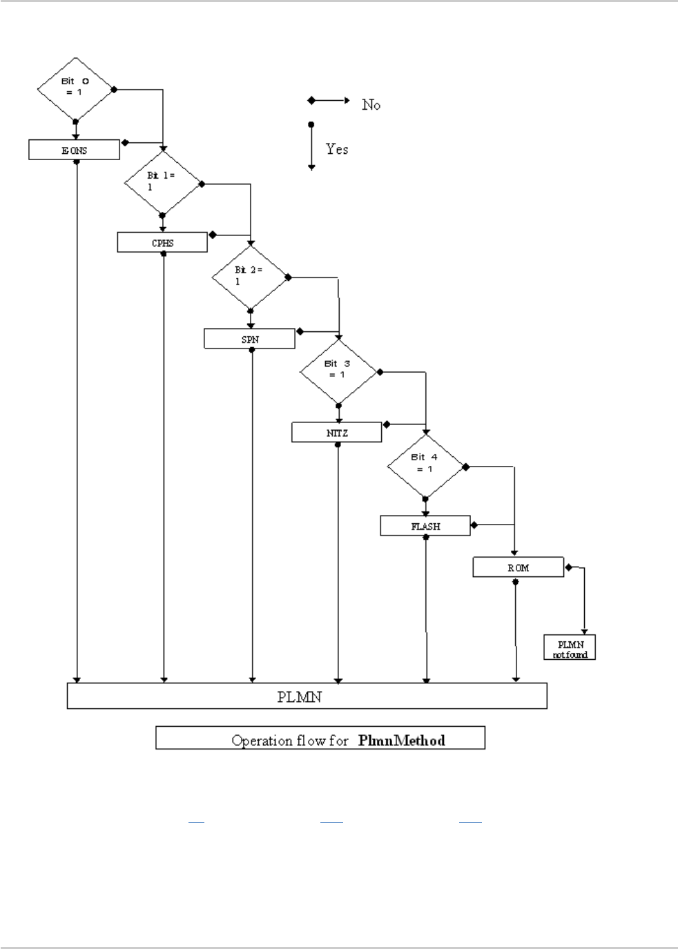
AT Commands Interface Guide for
Firmware 7.52
Error! Use the Home tab to apply Titre 1 to the text that you want to
appear here.
Error! Use the Home tab to apply Titre 2 to the text that you want to
appear here.
Rev. 1.0 Volume 2 March 7, 2014 219
For details, please refer to the following diagram:
Once a long name is found following this priority order, it is given as response to AT command.
Refer to 3GPP TS 24.008 [8], 3GPP TS 23.040 [11], 3GPP TS 22.042 [12] and COMMON PCN
HANDSET SPECIFICATION CPHS Phase 2 v4.2 for more information.

AT Commands Interface Guide for
Firmware 7.52
Error! Use the Home tab to apply Titre 1 to the text that you want to
appear here.
Error! Use the Home tab to apply Titre 2 to the text that you want to
appear here.
Rev. 1.0 Volume 2 March 7, 2014 220
15.6. Read Operator Name +COPN
15.6.1. Description
This command returns the list of all operator names (in numeric and alphanumeric format) stored in
the embedded module.
15.6.2. Syntax
Action command
AT+COPN
+COPN: <NumOper>,<AlphaOper>
[+COPN: <NumOper>,<AlphaOper>[…]]
OK
Read command
None
Test command
AT+COPN=?
OK
15.6.3. Parameters and Defined Values
<NumOper>:
operator in numeric format
<AlphaOper>:
operator in long alphanumeric format (see section "Operator names" of the
Appendixes for operator names description)
15.6.4. Parameter Storage
None.

AT Commands Interface Guide for
Firmware 7.52
Error! Use the Home tab to apply Titre 1 to the text that you want to
appear here.
Error! Use the Home tab to apply Titre 2 to the text that you want to
appear here.
Rev. 1.0 Volume 2 March 7, 2014 221
15.6.5. Examples
Command
Responses
AT+COPN
Note: Ask for list of all networks
+COPN: 20201"GR COSMOTE"
+COPN: 20205"vodafone GR"
+COPN: 20209"GR Q-TELECOM"
+COPN: 20210"TIM GR"
...
OK
AT+COPN=?
OK

AT Commands Interface Guide for
Firmware 7.52
Error! Use the Home tab to apply Titre 1 to the text that you want to
appear here.
Error! Use the Home tab to apply Titre 2 to the text that you want to
appear here.
Rev. 1.0 Volume 2 March 7, 2014 222
15.7. Automatic Time Zone Update +CTZU
15.7.1. Description
This command is used to enable or disable automatic time zone update via NITZ.
15.7.2. Syntax
Action command
AT+CTZU=<Mode>
OK
Read command
AT+CTZU?
+CTZU: <Mode>
OK
Test command
AT+CTZU=?
+CTZU: (list of supported <Mode>s)
OK
15.7.3. Parameters and Defined Values
<Mode>:
requested operation
0
disable automatic time zone update via NITZ (default value)
1
enable automatic time zone update via NITZ
15.7.4. Parameter Storage
The <Mode> parameter is stored in EEPROM without using AT&W command. The default value can
be restored using AT&F.

AT Commands Interface Guide for
Firmware 7.52
Error! Use the Home tab to apply Titre 1 to the text that you want to
appear here.
Error! Use the Home tab to apply Titre 2 to the text that you want to
appear here.
Rev. 1.0 Volume 2 March 7, 2014 223
15.7.5. Examples
Command
Responses
AT+CTZU=?
+CTZU: (0-1)
OK
AT+CTZU?
+CTZU: 0
OK
AT+CTZU=1
OK
Note: enable the automatic time zone update

AT Commands Interface Guide for
Firmware 7.52
Error! Use the Home tab to apply Titre 1 to the text that you want to
appear here.
Error! Use the Home tab to apply Titre 2 to the text that you want to
appear here.
Rev. 1.0 Volume 2 March 7, 2014 224
15.8. AT&T Command +PACSP
15.8.1. Description
This AT&T proprietary command indicates to the user the Network Selection Menu availability (ENS
support) (also called PLMN Mode bit in the AT&T specification).
This command is available when the ENS feature is activated (please refer to the +WBHV command
description) and when the AT&T EFTST (Terminal Support Table) SIM file is present in the SIM card.
15.8.2. Syntax
Action command
None
Read command
AT+PACSP?
[+PACSP<n>]
OK (or +CME ERROR: 515/+CME ERROR: 3/ERROR; see error explanations in the appendix)
Test command
None
Unsolicited response
+PACSP<n>

AT Commands Interface Guide for
Firmware 7.52
Error! Use the Home tab to apply Titre 1 to the text that you want to
appear here.
Error! Use the Home tab to apply Titre 2 to the text that you want to
appear here.
Rev. 1.0 Volume 2 March 7, 2014 225
15.8.3. Defined Values
<n>:
PLMN Mode bit value
0
PLMN bit 0
Reset the network selection mode to automatic and send the command
+PACSP0 to the client.
In this case, the client is the AT&T Connection Manager application.
The disabling of the network selection menu, if applicable, is performed
by the client.
1
PLMN bit 1
Set the mode to automatic and send the command +PACSP1 to the
client.
In this case, the client is the AT&T Connection Manager application.
The enabling of the network selection menu, if applicable, is performed
by the client.
This is only informational for the client, in order to display or not the network selection menu.
15.8.4. Parameter Storage
None
15.8.5. Examples
Command
Responses
+PACSP1
Note: At the embedded module initialization (pin code was
entered) the PLMN Mode bit is 1.
AT+PACSP?
Note: Ask for the PLMN Mode bit value
+PACSP1
OK

Rev. 1.0 Volume 2 March 7, 2014 226
Index
A, 70
ARMEE, 52
C, 105
CBST, 93
CCED, 13
CEER, 77
CGACT, 130
CGANS, 138
CGATT, 128
CGAUTO, 141
CGCLASS, 113
CGCMOD, 154
CGDATA, 134
CGDCONT, 125
CGEQMIN, 178
CGEQNEG, 186
CGEQREQ, 170
CGEREP, 159
CGPADDR, 164
CGQMIN, 144
CGQREQ, 149
CGREG, 156
CGSMS, 162
CICB, 84
COPN, 212
COPS, 197
CPLS, 194
CPOL, 202
CR, 88
CRC, 90
CREG, 9
CRLP, 99
CSNS, 86
CSQ, 7
CTZU, 214
D, 58
DL, 68
Dn, 79
DOPT, 101
DR, 109
DS, 107
FCLASS, 103
GH, 136
H, 72
ILRR, 96
N, 111
PACSP, 216
S0, 82, 137
WAC, 42
WATH, 74
WGPRS, 115
WLOC, 36
WMBS, 28
WOLM, 206
WOPN, 208
WPOW, 49
WPPP, 192
WREGC, 31
WSCAN, 40
WTBI, 166
WUBS, 44
WWSM, 47

1.0
March 7, 2014
Volume 3
AT Commands Interface Guide
for Firmware 7.52

Rev. 1.0 Volume 3 March 7, 2014 2
0BRelated Documents
This interface specification is based on the following recommendations:
[1] ETSI GSM 07.05: Digital cellular telecommunications system (Phase 2); Use of DTE-DCE
interface for Short Message Service (SMS) and Cell Broadcast Service (CBS)
[2] ETSI GSM 07.07: Digital cellular telecommunications system (Phase 2); AT command set for GSM
Mobile Equipment (ME)
[3] ITU-T Recommendation V.25 ter: Serial asynchronous automatic dialing and control
[4] ETSI GSM 03.40: Digital cellular telecommunications system (Phase 2); Technical implementation
of the Short Message Service (SMS) Point-to-Point (PP)
[5] ETSI GSM 03.38: Digital cellular telecommunications system (Phase 2); Alphabets and language-
specific information
[6] ETSI GSM 04.80: Digital cellular telecommunications system (Phase 2): Mobile radio interface
layer 3, Supplementary service specification, Formats and coding
[7] 3GPP 05.02: 3rd Generation Partnership Project; Technical Specification Group GSM/EDGE- Radio
Access Network; Multiplexing and multiple access on the radio path – 3GPP TS 05.02 V6.9.2
(2001-04)
[8] 3GPP 24.008: Mobile radio interface Layer 3 specification; Core network protocols; Stage 3
[9] 3GPP TS 11.11 Specification of the Subscriber Identity Module - Mobile Equipment (SIM-ME)
Interface
[10] 3GPP TS 05.08 Radio subsystem link control
[11] 3GPP TS 23.040 Technical realization of the Short Message Service (SMS);
[12] 3GPP TS 22.042 Network Identity and Time Zone (NITZ) service description; Stage 1
[13] 3GPP TS 51.011 Specification of the Subscriber Identity Module - Mobile Equipment (SIM-ME)
interface
[14] 3GPP TS 27-010 Terminal Equipment to User Equipment (TE-UE) multiplexer protocol
[15] 3GPP 23.014 Support of Dual Tone Multi Frequency (DTMF) signaling
[16] ISO 639 Langages Codes
[17] 3GPP 27 060 Packet domain; Mobile Station (MS) supporting Packet Switched services
[18] 3GPP TS 23.038 Alphabets and language-specific information
[19] 3GPP TS 27.005 Use of Data Terminal Equipment - Data Circuit terminating Equipment (DTE-
DCE) interface for Short Message Service (SMS) and Cell Broadcast Service (CBS)
[20] ETSI GSM 11.14 Digital cellular telecommunications system (Phase 2+); Specification of the SIM
Application Toolkit for the Subscriber Identity Module - Mobile Equipment (SIM - ME) interface
[21] 3GPP TS 23.003 Digital cellular telecommunications system (Phase 2+) (GSM); Universal Mobile
Telecommunications System (UMTS); Numbering, addressing and identification
[22] ETSI GSM 02.24 Digital cellular telecommunications system (Phase 2+) (GSM);Description of
Charge Advice Information (CAI)
[23] ETSI GSM 02.86 Digital cellular telecommunications system (Phase 2+) (GSM);Advice of Charge
(AoC) Supplementary Services - Stage 1
[24] ETSI GSM 02.90 Digital cellular telecommunications system (Phase 2+) (GSM);Unstructured
Supplementary Service Data (USSD) - Stage 1
[25] ETSI GSM 02.85 Digital cellular telecommunications system (Phase 2+) (GSM);Closed User
Group (CUG) Supplementary Services - Stage 1

AT Commands Interface Guide for
Firmware 7.52
Rev. 1.0 Volume 3 March 7, 2014 3
[26] 3GPP 27.007:Digital cellular telecommunications system (Phase 2+) (GSM); Universal Mobile
Telecommunications System (UMTS);AT command set for 3GPP User Equipment (UE) (Release
1999)
[27] 3GPP 23.107:Universal Mobile Telecommunications System (UMTS);QoS Concept and
Architecture (Release 1999)
[28] 3GPP 24.008: European digital cellular telecommunication system (Phase 2+). Mobile radio
interface layer 3 specification. (Release 1999)
[29] ETSI TS 102 221 "Smart Cards; UICC-Terminal interface; Physical and logical characteristics
(Release 1999)".

Rev. 1.0 Volume 3 March 7, 2014 4
1BContents
2BVolume 3
URELATED DOCUMENTSU .......................................................................................... 2
UCONTENTSU ............................................................................................................... 4
UVOLUME 3U ................................................................................................................. 4
U16.U UPHONEBOOKS COMMANDSU.............................................................................. 6
U16.1.U USelect Phonebook Memory Storage +CPBSU .................................................................... 6
U16.2.U UContact Selector +WCOSU.................................................................................................. 9
U16.3.U UWrite Phonebook Entry +CPBWU ..................................................................................... 11
U16.4.U URead Phonebook Entries +CPBRU ................................................................................... 17
U16.5.U UFind Phonebook Entries +CPBFU ..................................................................................... 22
U16.6.U UPhonebook Phone Search +CPBPU ................................................................................. 26
U16.7.U UMove Action in Phonebook +CPBNU ................................................................................ 30
U16.8.U UCreate and Delete a Phonebook Group +WPGWU ........................................................... 35
U16.9.U URead a Phonebook Group +WPGRU ................................................................................ 37
U16.10.U USettings of a Group +WPGSU ........................................................................................... 42
U16.11.U UDelete Calls Phonebook +WDCPU .................................................................................... 44
U16.12.U USubscriber Number +CNUMU............................................................................................ 46
U16.13.U USet Voice Mail Number +CSVMU ...................................................................................... 48
U16.14.U UAvoid Phonebook Init +WAIPU .......................................................................................... 50
U16.15.U USpecify Emergency Call Codes +WECCU ........................................................................ 52
U17.U USHORT MESSAGE COMMANDSU ...................................................................... 55
U17.1.U USelect Message Service +CSMSU .................................................................................... 55
U17.2.U UNew Message Indication +CNMIU ..................................................................................... 57
U17.3.U USet Text Mode Parameters +CSMPU ................................................................................ 64
U17.4.U UPreferred Message Format +CMGFU ................................................................................ 67
U17.5.U UPreferred Message Storage +CPMSU ............................................................................... 69
U17.6.U UService Center Address +CSCAU ..................................................................................... 73
U17.7.U UShow Text Mode Parameters +CSDHU ............................................................................ 75
U17.8.U UMore Messages to Send +CMMSU ................................................................................... 77
U17.9.U USend Message +CMGSU................................................................................................... 79
U17.10.U UWrite Message to Memory +CMGWU ............................................................................... 82
U17.11.U USend Message From Storage +CMSSU ............................................................................ 85
U17.12.U URead Message +CMGRU .................................................................................................. 87
U17.13.U UList Message +CMGLU ...................................................................................................... 92
U17.14.U UDelete Message +CMGDU ................................................................................................ 97
U17.15.U UNew Message Acknowledgement +CNMAU ................................................................... 100
U17.16.U UMessage Status Modification +WMSCU .......................................................................... 103

AT Commands Interface Guide for
Firmware 7.52
Rev. 1.0 Volume 3 March 7, 2014 5
U17.17.U UUn-change SMS Status +WUSSU ................................................................................... 105
U17.18.U UMessage Overwriting +WMGOU ..................................................................................... 108
U17.19.U UCopy Messages +WMCPU .............................................................................................. 110
U17.20.U USave Settings +CSASU ................................................................................................... 113
U17.21.U URestore Settings +CRESU ............................................................................................... 114
U17.22.U USelect Cell Broadcast Message Types +CSCBU ............................................................ 115
U17.23.U UCell Broadcast Message Identifiers +WCBMU ................................................................ 118
U18.U USIM COMMANDSU ............................................................................................. 120
U18.1.U UCard Identification +CCIDU.............................................................................................. 120
U18.2.U UActive Application Indication +WSAPPIU ........................................................................ 122
U18.3.U URequest IMSI +CIMIU ...................................................................................................... 124
U18.4.U UGeneric SIM Access +CSIMU .......................................................................................... 126
U18.5.U URestricted SIM Access +CRSMU .................................................................................... 129
U18.6.U UWrite Language Preference +WLPWU ............................................................................ 132
U18.7.U URead Language Preference +WLPRU ............................................................................. 134
U19.U USIM TOOLKIT COMMANDSU ............................................................................ 137
U19.1.U UOverview of SIM Application ToolKitU ............................................................................. 137
U19.2.U USIM ToolKit Set Facilities +STSFU .................................................................................. 140
U19.3.U USIM ToolKit Indication +STINU ........................................................................................ 143
U19.4.U USIM ToolKit Get Information +STGIU .............................................................................. 146
U19.5.U USIM ToolKit Give Response +STGRU ............................................................................. 155
U19.6.U USIM ToolKit Control Response +STCRU ......................................................................... 161
U19.7.U USIM ToolKit Indication +STRILU ...................................................................................... 163
U20.U USUPPLEMENTARY SERVICES COMMANDSU ................................................ 165
U20.1.U UList Current Calls +CLCCU .............................................................................................. 165
U20.2.U UCall Related Supplementary Services +CHLDU .............................................................. 169
U20.3.U UCalling Line Identification Presentation +CLIPU .............................................................. 172
U20.4.U UCalling Line Identification Restriction +CLIRU ................................................................. 175
U20.5.U UConnected Line Identification Presentation +COLPU ...................................................... 177
U20.6.U USupplementary Service Notifications +CSSNU ............................................................... 180
U20.7.U UUnstructured Supplementary Service Data +CUSDU ..................................................... 184
U20.8.U UCall Forwarding +CCFCU ................................................................................................ 187
U20.9.U UCall Waiting +CCWAU ..................................................................................................... 191
U20.10.U UKeypad Control +CKPDU................................................................................................. 194
U20.11.U UAdvice Of Charge +CAOCU............................................................................................. 196
U20.12.U UAccumulated Call Meter +CACMU .................................................................................. 198
U20.13.U UAccumulated Call Meter Maximum +CAMMU ................................................................. 200
U20.14.U UPrice per UNIT and Currency Table +CPUCU................................................................. 202
U20.15.U UClosed User Group +CCUGU .......................................................................................... 204
UINDEXU .................................................................................................................... 206

Rev. 1.0 Volume 3 March 7, 2014 6
16. Phonebooks Commands
16.1. Select Phonebook Memory Storage +CPBS
16.1.1. Description
This command selects phonebook memory storage.
Please refer to Recommendation 3GPP 11.11 U[9]U for more details.
16.1.2. Syntax
Action command
AT+CPBS=<storage>[,<pin2>]
OK
Read command
AT+CPBS?
+CPBS: <storage>,<used>,<total>
OK
Test command
AT+CPBS=?
+CPBS: (list of supported <storage>s)
OK

AT Commands Interface Guide for
Firmware 7.52
Error! Use the Home tab to apply Titre 1 to the text that you want
to appear here.
Error! Use the Home tab to apply Titre 2 to the text that you want
to appear here.
Rev. 1.0 Volume 3 March 7, 2014 7
16.1.3. Parameters and Defined Values
<storage>:
phonebook memory storage
"SM"
ADN Abbreviated Dialing Numbers (SIM phonebook)
"FD"
FDN Fixed Dialing Numbers (SIM restricted phonebook)
"ON"
MSISDN (SIM own numbers)
"EN"
ECC Emergency Call Codes (SIM or ME)
"LD"
LND Last Number Dialed
"MC"
ME missed (unanswered received) calls list
"ME"
ME phonebook
"MT"
combined ME and SIM phonebook (ME+SM)
"RC"
ME received calls list
"SN"
SDN Service Dialing Numbers (SIM special service numbers)
<pin2>:
Personal Identification Number 2.
<used>:
used locations in selected memory
integer type
<total> :
total number of locations in selected memory
integer type
16.1.4. Parameter Storage
None.

AT Commands Interface Guide for
Firmware 7.52
Error! Use the Home tab to apply Titre 1 to the text that you want
to appear here.
Error! Use the Home tab to apply Titre 2 to the text that you want
to appear here.
Rev. 1.0 Volume 3 March 7, 2014 8
16.1.5. Examples
Command
Responses
AT+CPBS="SM"
OK
Note: Select ADN phonebook
Note: ADN phonebook is selected
AT+CPBS=?
Note: Possible values
+CPBS:
("SM","LD","MC","ON","ME","RC","MT","SN","EN")
OK
AT+CPBS?
+CPBS: "SM",10,20
OK
Note: Get current phonebook memory storage
Note: ADN phonebook selected, 10 locations used, 20 locations
available
16.1.6. Notes
When a SIM is inserted, on ADN and FDN activation: when FDN has been activated with the +CLCK
command, the selection of ADN phonebook is possible only if ADN status bit3 is set to 1 (EF file
"readable and updatable when invalidated").
When a USIM is inserted: there is no such a restriction..
Selection of ADN phonebook when FDN is active is SIM dependent.
Selection of "FD" phonebook with <pin2>, when <pin2> is already verified, will give "+CME ERROR:
3".
The previously selected phonebook remains the same when the embedded module is switched on or
reset, even if a new SIM card is inserted. However, in the case when the replacement SIM card does
not contain any selected phonebook, the ADN phonebook is selected.
The maximum number of entries for ME phonebook is set to 500.
When the SIM is not present, the following emergency numbers are available: 000, 08, 112, 110, 118,
119, 911, 999.
When a SIM is present, the following emergency numbers are available: 112, 911, emergency
numbers from ECC SIM files (if existing).
The following emergency numbers are stored in EEPROM:
112
911
999
08
So, "EN" will be available even if ECC SIM file is not present.

AT Commands Interface Guide for
Firmware 7.52
Error! Use the Home tab to apply Titre 1 to the text that you want
to appear here.
Error! Use the Home tab to apply Titre 2 to the text that you want
to appear here.
Rev. 1.0 Volume 3 March 7, 2014 9
16.2. Contact Selector +WCOS
16.2.1. Description
This Sierra Wireless proprietary command allows extended contact display to be enabled\disabled.
16.2.2. Syntax
Action command
AT+WCOS=<mode>
OK
Read command
AT+WCOS?
+WCOS: <mode>
OK
Test command
AT+WCOS=?
+WCOS: (list of supported <mode>s)
OK
16.2.3. Parameters and Defined Values
<mode>:
extended contact mode

AT Commands Interface Guide for
Firmware 7.52
Error! Use the Home tab to apply Titre 1 to the text that you want
to appear here.
Error! Use the Home tab to apply Titre 2 to the text that you want
to appear here.
Rev. 1.0 Volume 3 March 7, 2014 10
0
select the SIM contacts (default mode)
1
select the extended contacts for phonebook entries
2
reserved
Customer application should not use this value.
16.2.4. Parameter Storage
The <mode> parameter is stored in EEPROM.
16.2.5. Examples
Command
Responses
AT+WCOS=?
Note: Possible values?
+WCOS: (0-2)
OK
Note: Possible responses
AT+WCOS=1
Note: Extended contact selected
OK
AT+WCOS?
Note: Test command
+WCOS: 1
OK
Note: Extended contact selected

AT Commands Interface Guide for
Firmware 7.52
Error! Use the Home tab to apply Titre 1 to the text that you want
to appear here.
Error! Use the Home tab to apply Titre 2 to the text that you want
to appear here.
Rev. 1.0 Volume 3 March 7, 2014 11
16.3. Write Phonebook Entry +CPBW
16.3.1. Description
This command writes a phonebook entry in an index location number of the current phonebook
memory storage.
16.3.2. Syntax
Depending on the context several possibilities:
The entry is stored in the ADN phonebook and AT+WCOS=0:
Action command
AT+CPBW=[<index>][,<number>[,<type>[,<text>]]]
OK
The entry is stored in the ADN phonebook and AT+WCOS=1:
Action command
AT+CPBW=<index>[,<number>[,<type>[,<text>[,<phb_group>]]]]
OK
The entry is stored in the ME phonebook and AT+WCOS=0:
Action command
AT+CPBW=<index>[,<number>[,<type>[,<text>]]]
OK
The entry is stored in the ME phonebook and AT+WCOS=1:
Action command
AT+CPBW=<index>[,<number>[,<type>[,<text>[,<contact>[,<phb_group>]]]]]
OK

AT Commands Interface Guide for
Firmware 7.52
Error! Use the Home tab to apply Titre 1 to the text that you want
to appear here.
Error! Use the Home tab to apply Titre 2 to the text that you want
to appear here.
Rev. 1.0 Volume 3 March 7, 2014 12
Read command
None
Test command
AT+CPBW=?
+CPBW: (list of supported <index>s),[<nlength>],(list of supported
<type>s),[<tlength>]
OK
16.3.3. Parameters and Defined Values
<index>:
location in memory storage
range of possible values depending on the capacity of the phonebook memory
integer type
<number>:
phone number in ASCII format
string type
<type>:
TON/NPI (type of address octet in integer format); default 145 when dialing string
includes international access code character “+”, otherwise 129
129
ISDN / telephony numbering plan, national / international unknown
145
ISDN / telephony numbering plan, international number
161
ISDN / telephony numbering plan, national number
128-255
other values (refer GSM 04.08 section 10.5.4.7 U[6]U)
<text>:
associated contact name
string type (see Note below)
SIM dependant for the ADN phonebook (use AT+CPBW=?)
<phb_group>:
phonebook group number in which the entry should be saved
range value (1-10)
<nlength>:
max length of field <number>
integer type

AT Commands Interface Guide for
Firmware 7.52
Error! Use the Home tab to apply Titre 1 to the text that you want
to appear here.
Error! Use the Home tab to apply Titre 2 to the text that you want
to appear here.
Rev. 1.0 Volume 3 March 7, 2014 13
<tlength>:
max length of field <text>
integer type
<contact>:
This parameter gathers the following parameters:
<num_Mobile>, <num_Work>, <num_Fax>, <num_Data>, <Email>, <Address>
<num_Mobile>:
phone number (dedicated for mobile phone number for example)
up to 20 digits
<num_Work>:
phone number (dedicated for work phone number for example)
up to 20 digits
<num_Fax>:
phone number (dedicated for fax phone number for example)
up to 20 digits
<num_Data>:
phone number (dedicated for data phone number for example)
up to 20 digits
<Email>:
e-mail address
string type
up to 56 characters
<Address>:
mail address
string type
up to 56 characters
Note: For the <text> parameter all strings starting with "80" , "81" or "81" are considered in UCS2 format.
The +CSCS (Select Character Set) command does not affect the format for phonebook entries.
16.3.4. Parameter Storage
None.
16.3.5. Examples
Command
Responses
AT+CPBS="SM"
Note: ADN phonebook
OK
AT+CPBS?
Note: Get current memory storage
+CPBS:"SM",1,10
OK
Note: ADN phonebook is selected, 1 location is used and 10
locations are available

AT Commands Interface Guide for
Firmware 7.52
Error! Use the Home tab to apply Titre 1 to the text that you want
to appear here.
Error! Use the Home tab to apply Titre 2 to the text that you want
to appear here.
Rev. 1.0 Volume 3 March 7, 2014 14
Command
Responses
AT+WCOS=0
Note: Phonebook not extended
OK
AT+CPBW=?
Note: Test command
+CPBW: (1-50),20,(128-255),10
OK
Note: 50 locations, phone number = 20 digits max, TON/NPI = 128-
255, text length = 10 character max
AT+CPBW=5,"112",129,"SOS"
Note: Write at location 5
OK
Note: Location 5 written
AT+CPBR=5
Note: Read the entry at location 5
+CPBR: 5,"112",129,"SOS"
OK
AT+CPBS?
Note: Get current memory storage
+CPBS: "SM",2,10
OK
Note: ADN phonebook is selected, 2 locations are used and 10
locations are available
AT+CPBW=5,"01290917",129,"Jacky"
Note: Overwrite location 5
OK
Note: Location 5 overwritten
AT+CPBW=6,"01292349",129,"8000410042"
OK
Note: Write location 6 (UCS2 format for the<text> field)
Note: Location 6 is written
AT+CPBW=8,"01292349",129,"80xyz"
Note: Write location
OK
Note: Location 8 is written. The string has a wrong UCS2 format, it
is therefore considered as an ASCII string.
AT+CPBW=5,"01290917",129,"Jacky",1
+CME ERROR: 3
Note: Write an extended entry
Note: Error because +WCOS: 0
AT+WCOS=1
Note: Phonebook extended
OK
AT+CPBW=5,""01290917"",129,"Jacky",1
Note: Write an extended entry
OK
AT+WCOS=0
Note: Phonebook not extended
OK
AT+CPBS="ME"
Note: ME phonebook
OK
AT+CPBS?
Note: How many entries are used ?
+CPBS: "ME",2,500
Note: in ME phonebook, 2 locations are used out of 500 available
locations

AT Commands Interface Guide for
Firmware 7.52
Error! Use the Home tab to apply Titre 1 to the text that you want
to appear here.
Error! Use the Home tab to apply Titre 2 to the text that you want
to appear here.
Rev. 1.0 Volume 3 March 7, 2014 15
Command
Responses
AT+CPBW=1,"0123456798",129,"first entry"
Note: Write an not extended entry
OK
AT+CPBR=1
Note: Read the first entry
+CPBR: 1,"0123456798",129,"first entry"
OK
AT+WCOS=1
Note: Phonebook extended
OK
AT+CPBW=1,"0123456798",129,"first entry"
Note: Write an entry not extended
OK
AT+CPBW=2,"9876543210",129,"secondentry"
,"6543210987",129
Note: Write an entry extended
OK
AT+CPBR=1,2
Note: Read entry 1 and 2
+CPBR: 1,"0123456798",129,"first
entry","",128,"",128,"",128,"",128,"","",0
+CPBR: 2,"9876543210",129,"second
entry","6543210987",129,"",128,"",128,"",128
,"","",0
OK
AT+CPBW=13,"+331290909",145,"Fred","0141
284549",129,"0600003210",129,"0141280000
",129,"019876543210",
129,"fred@mail_address.com", "Becker
Street London",1
Note: Write location with Contact and Phonebook Group n°1
OK
Note: Location 13 is written
AT+CPBW=,"+33145221100",145,"SOS"
Note: Write at the first location available
OK
Note: First location available is written
AT+CPBS="SM"
Note: ADN phonebook
OK
AT+WCOS?
+WCOS: 1
OK
Note: Extended phonebook
AT+CPBW=1
Note: Delete entry at first location
OK
AT+CPBW=1,"0123456",,"test",1
Note: Add an extended entry in SIM with group number (1)
OK
AT+CPBR=1
+CPBR:1,"0123456",129,"test",1
OK

AT Commands Interface Guide for
Firmware 7.52
Error! Use the Home tab to apply Titre 1 to the text that you want
to appear here.
Error! Use the Home tab to apply Titre 2 to the text that you want
to appear here.
Rev. 1.0 Volume 3 March 7, 2014 16
Command
Responses
AT+CPBW=1,””,,”No number”
Note : Write an empty number. The TON/NPI is omitted
OK
AT+CPBW=2,”7654321”,161,”test2”,1
OK
AT+CPBR=2
+CPBR:2,"7654321",161,"test2",1
OK
16.3.6. Notes
This command is not allowed when the fixed dialing phonebook (FDN) is locked. Moreover,
when the FDN is unlocked, PIN2 is required to write in the FDN phonebook. If PIN2
authentication has been performed during the current session, the +CPBW command with
FDN is allowed.
"RC" and "MC" phonebooks can only be erased by using +CPBW. Adding field and/or
modifying field is not allowed for these phonebooks.
This command is not allowed for "EN", "LD", "MC", "RC", "MT", "SN" phonebooks, which can
not be written.
If the AT+WCOS=1 command was used, the request would include the ‘Contact’ structure.
When an empty number is written, the <type> parameter should be omitted. When this entry
is read, the <type> in the response is equal to 128 (unknown) (see U+CPBRU command).

AT Commands Interface Guide for
Firmware 7.52
Error! Use the Home tab to apply Titre 1 to the text that you want
to appear here.
Error! Use the Home tab to apply Titre 2 to the text that you want
to appear here.
Rev. 1.0 Volume 3 March 7, 2014 17
16.4. Read Phonebook Entries +CPBR
16.4.1. Description
This command returns phonebook entries for a range of locations from the current phonebook
memory storage selected with +CPBS.
16.4.2. Syntax
Depending on the context several possibilities:
The entry is stored in the ADN phonebook and AT+WCOS=0:
Action command
AT+CPBR=<first_entry>[,<last_entry>]
+CPBR: <loc>,<num>,<type>,<name>
[+CPBR: <loc>,<num>,<type>,<name>[…]]
OK
The entry is stored in the ADN phonebook and AT+WCOS=1:
Action command
AT+CPBR=<first_entry>[,<last_entry>]
+CPBR: <loc>,<num>,<type>,<name>,<phb_group>
[+CPBR: <loc>,<num>,<type>,<name>,<phb_group>[…]]
OK
The entry is stored in the ME phonebook and AT+WCOS=0:
Action command
AT+CPBR=<first_entry>[,<last_entry>]
+CPBR: <loc>,<num>,<type>,<name>
[+CPBR: <loc>,<num>,<type>,<name>[…]]
OK
The entry is stored in the ME phonebook and AT+WCOS=1:

AT Commands Interface Guide for
Firmware 7.52
Error! Use the Home tab to apply Titre 1 to the text that you want
to appear here.
Error! Use the Home tab to apply Titre 2 to the text that you want
to appear here.
Rev. 1.0 Volume 3 March 7, 2014 18
Action command
AT+CPBR=<first_entry>[,<last_entry>]
+CPBR:<loc>,<num>,<type>,<name>,<contact>,<phb_group>
[+CPBR:<loc>,<num>,<type>,<name>,<contact>,<phb_group>[…]]
OK
Read command
None
Test command
AT+CPBR=?
+CPBR: (list of supported <loc>s),<nlength>,<tlength>
OK
16.4.3. Parameters and Defined Values
<first_entry>:
first location (or range of locations) where to read phonebook entry
<last_entry>:
last location (or range of locations) where to read phonebook entry
<type>:
TON/NPI Type of address octet (refer GSM 04.08 subclause 10.5.4.7 U[6]U)
integer type
129
ISDN / telephony numbering plan, national / international unknown
145
ISDN / telephony numbering plan, international number
161
ISDN / telephony numbering plan, national number
128-255
other values (refer GSM 04.08 section 10.5.4.7 U[6]U)
<nlength>:
value indicating the maximum length of field <num>
integer type
<tlength>:
value indicating the maximum length of field <name>
integer type
<loc>:
phonebook index
integer type
<phb_group>:
phonebook group
range value (1-10)

AT Commands Interface Guide for
Firmware 7.52
Error! Use the Home tab to apply Titre 1 to the text that you want
to appear here.
Error! Use the Home tab to apply Titre 2 to the text that you want
to appear here.
Rev. 1.0 Volume 3 March 7, 2014 19
<num>:
phone number
string type
<name>:
name associated with the phone number
up to 30 ASCII characters or 13 UCS2
<contact>:
this parameter gathers the following parameters:
<num_Mobile>, <num_Work>, <num_Fax>, <num_Data>,
<Email>,<Address>
<num_Mobile>:
phone number (dedicated for mobile phone number for example)
up to 20 digits
<num_Work>:
phone number (dedicated for work phone number for example)
up to 20 digits
<num_Fax>:
phone number (dedicated for fax phone number for example)
up to 20 digits
<num_Data>:
phone number (dedicated for data phone number for example)
up to 20 digits
<Email>:
e-mail address
string type
up to 56 characters
<Address>:
mail address
string type
up to 56 characters
16.4.4. Parameter Storage
None.
16.4.5. Examples
Command
Responses
AT+CPBR=?
+CPBR: (1-50),20,10
OK
Note: Test command
Note: 50 locations (from 1 to 50), max length for phone number is
20 digits, 10 characters max for name
AT+WCOS?
+WCOS: 0
OK

AT Commands Interface Guide for
Firmware 7.52
Error! Use the Home tab to apply Titre 1 to the text that you want
to appear here.
Error! Use the Home tab to apply Titre 2 to the text that you want
to appear here.
Rev. 1.0 Volume 3 March 7, 2014 20
Command
Responses
Note: Test command
Note: Contact not selected
AT+CPBR=12,14
+CPBR: 12,"112",129,"Emergency"
+CPBR: 13,"+331290909",145,"Fred"
+CPBR: 14,"0146290808",129,"Zazi"
OK
Note: Read entries from 12 to 14
Note: Display locations 12,13,14 with location, number, type
(TON/NPI), name
AT+CPBR=10
+CPBR: 10,"0146290921",129,"Rob"
OK
Note: Read entry 10
Note: Display location 10
AT+CPBR=11
+CPBR: 11,"0146290921",129,"8000010002FFFF"
OK
Note: Read entry 11 (UCS2 format)
Note: Display location 11
AT+CPBS="ME"
Note: Flash memory
OK
AT+WCOS=1
OK
Note: Contact selected
AT+CPBR=13
+CPBR:
13,"+331290909",145,"Fred","0141284549",129,
"0600003210",129
,"0141280000",129,"019876543210",129,"fred@m
ail_address.com","Becker Street London",1
OK
Note: Read entry
Note: Display location 13 with location, number, type (TON/NPI),
name and contact and phonebook group n°1
AT+CPBS="SM"
Note: ADN phonebook
OK
AT+CPBR=1
+CPBR=1,"0123456",129,"test"
OK
AT+WCOS=0
OK
AT+CPBW=1,””,,”No number”
OK
AT+CPBR=1
+CPBR: 1,””,128,”No number”
OK

AT Commands Interface Guide for
Firmware 7.52
Error! Use the Home tab to apply Titre 1 to the text that you want
to appear here.
Error! Use the Home tab to apply Titre 2 to the text that you want
to appear here.
Rev. 1.0 Volume 3 March 7, 2014 21
16.4.6. Notes
For all phonebook read commands (+CPBR, +CPBF, +CPBN, +CPBP, +CNUM), the
TON/NPI MSB of each number is set to 1 (ex: a TON/NPI stored as 17 is displayed as 145).
If the AT+WCOS=1 command was used, the response will include <Contact> structure.

AT Commands Interface Guide for
Firmware 7.52
Error! Use the Home tab to apply Titre 1 to the text that you want
to appear here.
Error! Use the Home tab to apply Titre 2 to the text that you want
to appear here.
Rev. 1.0 Volume 3 March 7, 2014 22
16.5. Find Phonebook Entries +CPBF
16.5.1. Description
This command returns phonebook entries with alphanumeric fields starting with a given pattern. The
AT+CPBF="" command can be used to display all phonebook entries sorted in alphabetical order.
This command is not allowed for "LD", "RC", "MC" phonebooks and for the "EN" phonebook, which
does not contain alphanumeric fields.
It is possible to use this command with UCS2 strings. If a wrong UCS2 format is entered, the string is
considered as an ASCII string.
16.5.2. Syntax
Depending on the context several responses to the command are possible:
The entry is stored in the ADN phonebook and AT+WCOS=0:
Action command
AT+CPBF=<string>
+CPBF: <loc>,<num>,<type>,<name>
OK
The entry is stored in the ADN phonebook and AT+WCOS=1
Action command
AT+CPBF=<string>
+CPBF: <loc>,<num>,<type>,<name>,<phb_group>
OK
The entry is stored in the ME phonebook and AT+WCOS=0
Action command
AT+CPBF=<string>
+CPBF: <loc>,<num>,<type>,<name>
OK

AT Commands Interface Guide for
Firmware 7.52
Error! Use the Home tab to apply Titre 1 to the text that you want
to appear here.
Error! Use the Home tab to apply Titre 2 to the text that you want
to appear here.
Rev. 1.0 Volume 3 March 7, 2014 23
The entry is stored in the ME phonebook and AT+WCOS=1
Action command
AT+CPBF=<string>
+CPBF: <loc>,<num>,<type>,<name>,<contact>,<phb_group>
OK
Read command
None
Test command
AT+CPBF=?
+CPBF: [<nlength>],[<tlength>],[<glength>],[<slength>],[<elength>]
OK
16.5.3. Parameters and Defined Values
<string>:
searched pattern string (depends on the format of data stored in the phonebooks)
<loc>:
location number (20 digits max)
<num>:
phone number (20 digits max)
<type>:
TON/NPI Type of address octet (refer GSM 04.08 subclause 10.5.4.7 U[6]U)
integer type
129
ISDN / telephony numbering plan, national / international unknown
145
ISDN / telephony numbering plan, international number
161
ISDN / telephony numbering plan, national number
128-255
other values (refer GSM 04.08 section 10.5.4.7 U[6]U)
<phb_group>:
phonebook group
range value (1-10)
<name>:
name associated with the phone number .
up to 30 ASCII characters or 13 UCS2
<contact>:
this parameter gathers the following parameters:
<num_Mobile>, <num_Work>, <num_Fax>, <num_Data>, <Email>,<Address>

AT Commands Interface Guide for
Firmware 7.52
Error! Use the Home tab to apply Titre 1 to the text that you want
to appear here.
Error! Use the Home tab to apply Titre 2 to the text that you want
to appear here.
Rev. 1.0 Volume 3 March 7, 2014 24
<num_Mobile>:
phone number (dedicated for mobile phone number for example)
up to 20 digits
<num_Work>:
phone number (dedicated for work phone number for example)
up to 20 digits
<num_Fax>:
phone number (dedicated for fax phone number for example)
up to 20 digits
<num_Data>:
phone number (dedicated for data phone number for example)
up to 20 digits
<Email>:
e-mail address
string type
up to 56 characters
<Address>:
mail address
string type
up to 56 characters
16.5.4. Parameter Storage
None.
16.5.5. Examples
Command
Responses
AT+CPBF=?
+CPBF: 20,14
OK
Note: Test command
Note: Max length for phone number is 20 digits, 14 characters for the text
AT+CPBF="E"
+CPBF: 12,"112",129,"Emergency"
+CPBF: 15,"+331290101",145,"Eric"
OK
Note: Read entries with "E"
Note: Display locations with text field starting with "E"
AT+CPBF="H"
Note: Read entries with "H"
+CME ERROR: 22
Note: No entry found
AT+CPBF="800001"
+CPBF: 11,"0146290921",129,"8000010002FFFF"
OK

AT Commands Interface Guide for
Firmware 7.52
Error! Use the Home tab to apply Titre 1 to the text that you want
to appear here.
Error! Use the Home tab to apply Titre 2 to the text that you want
to appear here.
Rev. 1.0 Volume 3 March 7, 2014 25
Command
Responses
Note: Read entries starting with 0001 UCS2
character
Note: Display locations with text field starting with 0001 UCS2 character
AT+CPBF="8045C"
Note: Read entries with "8045C" (ASCII format)
+CME ERROR: 22
Note: No entry found. The string has a wrong UCS2 format, it is therefore
considered as an ASCII string
AT+CPBS="SM"
Note: ADN phonebook
OK
AT+WCOS=0
Note: Phonebook not extended
OK
AT+CPBF="Test"
Note: Read entries with "Test"
+CPBF: 1,"0123456789",129,"Test ADN"
Note: Display locations with text field starting with "Test"
AT+WCOS=1
Note: Phonebook extended
OK
AT+CPBF="Test"
Note: Read entries with "Test"
+CPBF: 1,"0123456789",129,"Test ADN",0
Note: Display locations with text field starting with "Test" extended entry
AT+CPBS="ME"
Note: Flash phonebook
OK
AT+WCOS=0
Note: Phonebook not extended
OK
AT+CPBF="Test"
Note: Read entries with "Test"
+CPBF: 1,"0123456789",129,"Test ME"
Note: Display locations with text field starting with "Test"
AT+WCOS=1
Note: Phonebook extended
OK
AT+CPBF="Test"
+CPBF: 1,"0123456789",129,"Test
ME","9876543210",129,"",128,"",128,"",128,"e_mail@ma
il_address.com",
"post address",0
Note: Read entries with "Test"
Note: Display locations with text field starting with "Test", extended entry
AT+WCOS=0
OK
AT+CPBW=1,"",,"No number"
OK
AT+CPBF="No number"
+CPBF: 1,"",128,"No number"
OK

AT Commands Interface Guide for
Firmware 7.52
Error! Use the Home tab to apply Titre 1 to the text that you want
to appear here.
Error! Use the Home tab to apply Titre 2 to the text that you want
to appear here.
Rev. 1.0 Volume 3 March 7, 2014 26
16.6. Phonebook Phone Search +CPBP
16.6.1. Description
This Sierra Wireless proprietary command orders the product to search in the phonebook for an item
with the same phone number as provided in the parameter.
If two different entries of the selected phonebook have the same number, the entry returned by
+CPBP command is the first one written using +CPBW command..
16.6.2. Syntax
Depending on the context several responses to the command are possible:
The entry is stored in the ADN phonebook and AT+WCOS=0:
Action command
AT+CPBP=<number>
+CPBP: <index>,<number>,<type>,<text>
OK
The entry is stored in the ADN phonebook and AT+WCOS=1
Action command
AT+CPBP=<number>
+CPBP: <index>,<number>,<type>,<text>,<phb_group>
OK
The entry is stored in the ME phonebook and AT+WCOS=0
Action command
AT+CPBP=<number>
+CPBP: <index>,<number>,<type>,<text>
OK
The entry is stored in the ME phonebook and AT+WCOS=1

AT Commands Interface Guide for
Firmware 7.52
Error! Use the Home tab to apply Titre 1 to the text that you want
to appear here.
Error! Use the Home tab to apply Titre 2 to the text that you want
to appear here.
Rev. 1.0 Volume 3 March 7, 2014 27
Action command
AT+CPBP=<number>
+CPBP: <index>,<number>,<type>,<text>,<contact>,<phb_group>
OK
Read command
None
Test command
AT+CPBP=?
+CPBP: (list of supported <index>s),<nlength>,<tlength>
OK
16.6.3. Parameters and Defined Values
<index>:
location in memory storage
range of possible values depending on the capacity of the phonebook memory
integer type
<number>:
phone number in ASCII format
string type
<type>:
TON/NPI Type of address octet (refer GSM 04.08 subclause 10.5.4.7 U[6]U)
integer type
129
ISDN / telephony numbering plan, national / international unknown
145
ISDN / telephony numbering plan, international number
161
ISDN / telephony numbering plan, national number
128-255
other values (refer GSM 04.08 section 10.5.4.7 U[6]U)
<text>:
associated contact name
string type (see note below)
SIM dependant for the ADN phonebook (use AT+CPBW=?)
<phb_group>:
phonebook group number
range value (1-10)
<nlength>:
max length of field <number>
integer type

AT Commands Interface Guide for
Firmware 7.52
Error! Use the Home tab to apply Titre 1 to the text that you want
to appear here.
Error! Use the Home tab to apply Titre 2 to the text that you want
to appear here.
Rev. 1.0 Volume 3 March 7, 2014 28
<tlength>:
max length of field <text>
integer type
<contact>:
this parameter gathers the following parameters:
<num_Mobile>, <num_Work>, <num_Fax>, <num_Data>, <Email>,<Address>
<num_Mobile>:
phone number (dedicated for mobile phone number for example)
up to 20 digits
<num_Work>:
phone number (dedicated for work phone number for example)
up to 20 digits
<num_Fax>:
phone number (dedicated for fax phone number for example)
up to 20 digits
<num_Data>:
phone number (dedicated for data phone number for example)
up to 20 digits
<Email>:
e-mail address
string type
up to 56 characters
<Address>:
mail address
string type
up to 56 characters
16.6.4. Parameter Storage
None.
16.6.5. Examples
Command
Responses
AT+CPBP=?
Note: Test command
+CPBP: (1-50),20,10
OK
Note: 50 locations (from 1 to 50), max length for phone number is
20 digits, max length for text is 10 characters
AT+CPBP="+331290101"
+CPBP: 15,"+331290101",145,"Eric"
OK
Note: Search entries corresponding to this phone
number
Note: Display the entry corresponding to the specified phone
number

AT Commands Interface Guide for
Firmware 7.52
Error! Use the Home tab to apply Titre 1 to the text that you want
to appear here.
Error! Use the Home tab to apply Titre 2 to the text that you want
to appear here.
Rev. 1.0 Volume 3 March 7, 2014 29
Command
Responses
AT+CPBP="01290202"
Note: Search entries corresponding to this phone
number
+CPBP: 15,"+331290202",145,"David"
OK
Note: Display the entry corresponding to the specified phone
number
AT+CPBP="+331288575"
+CPBP: 15,"+331290101",145,"8045682344FFFF"
OK
Note: Search entries corresponding to this phone
number
Note: Display the entry corresponding to the specified phone
number (UCS2 format)
AT+CPBS="SM"
Note: ADN phonebook
OK
AT+WCOS=0
Note: Phonebook not extended
OK
AT+CPBP="0123456789"
Note: Search entries corresponding to this phone
number
+CPBP: 1,"0123456789",129,"Test ADN"
OK
Note: Display the entry corresponding to the specified phone
number
AT+WCOS=1
Note: Phonebook extended
OK
AT+CPBP="0123456789"
Note: Search entries corresponding to this phone
number
+CPBP: 1,"0123456789",129,"Test ADN",0
OK
AT+CPBS="ME"
Note: ME phonebook
OK
AT+WCOS=0
Note: Phonebook not extended
OK
AT+CPBP="0123456789"
Note: Search entries corresponding to this phone
number
+CPBP: 1,"0123456789",129,"Test ME"
OK
AT+WCOS=1
Note: Phonebook extended
OK
AT+CPBP="0123456789"
Note: Search entries corresponding to this phone
number
+CPBP: 1,"0123456789",129,"Test
ME","9876543210",129,"",128,"",128,"",128,"e
_mail@somewhere.com","postal address",0
OK

AT Commands Interface Guide for
Firmware 7.52
Error! Use the Home tab to apply Titre 1 to the text that you want
to appear here.
Error! Use the Home tab to apply Titre 2 to the text that you want
to appear here.
Rev. 1.0 Volume 3 March 7, 2014 30
16.7. Move Action in Phonebook +CPBN
16.7.1. Description
This Sierra Wireless proprietary command performs a forward or backward move in the phonebook (in
alphabetical order). It is not allowed for the "EN" phonebook which does not contain alphanumeric
fields.
16.7.2. Syntax
Depending on the context, several responses to the command are possible:
The entry is stored in the ADN phonebook and AT+WCOS=0:
Action command
AT+CPBN=<mode>
+CPBN: <index>,<number>,<type>,<name>
OK
The entry is stored in the ADN phonebook and AT+WCOS=1
Action command
AT+CPBN=<mode>
+CPBN: <index>,<number>,<type>,<name>,<phb_group>
OK
The entry is stored in the ME phonebook and AT+WCOS=0
Action command
AT+CPBN=<mode>
+CPBN: <index>,<number>,<type>,<name>
OK

AT Commands Interface Guide for
Firmware 7.52
Error! Use the Home tab to apply Titre 1 to the text that you want
to appear here.
Error! Use the Home tab to apply Titre 2 to the text that you want
to appear here.
Rev. 1.0 Volume 3 March 7, 2014 31
The entry is stored in the ME phonebook and AT+WCOS=1
Action command
AT+CPBN=<mode>
+CPBN: <index>,<number>,<type>,<name>,<contact>,<phb_group>
OK
Read command
None
Test command
AT+CPBN=?
+CPBN: (list of supported <mode>s)
OK
16.7.3. Parameters and Defined Values
<mode>:
requested entry to be displayed
0
first item
1
last item
2
next valid item in alphabetical order
3
previous valid item in alphabetical order
4
last item read (usable only if a read operation has been performed on the current
phonebook)
5
last item written (usable only if a write operation has been performed on the
current phonebook)
<index>:
location in memory storage
range of possible values depending on the capacity of the phonebook memory
integer type
<number>:
phone number in ASCII format
string type
<type>:
TON/NPI Type of address octet (refer GSM 04.08 subclause 10.5.4.7 U[6]U)
integer type
129
ISDN / telephony numbering plan, national / international unknown
145
ISDN / telephony numbering plan, international number

AT Commands Interface Guide for
Firmware 7.52
Error! Use the Home tab to apply Titre 1 to the text that you want
to appear here.
Error! Use the Home tab to apply Titre 2 to the text that you want
to appear here.
Rev. 1.0 Volume 3 March 7, 2014 32
161
ISDN / telephony numbering plan, national number
128-255
other values (refer GSM 04.08 section 10.5.4.7 U[6]U)
<phb_group>:
phonebook group number
range :1-10
<name>:
name of the group.
up to 30 ASCII characters or 13 UCS2
<contact>:
this parameter gathers the following parameters:
<num_Mobile>, <num_Work>, <num_Fax>, <num_Data>, <Email>,<Address>
<num_Mobile>:
phone number (dedicated for mobile phone number for example)
up to 20 digits
<num_Work>:
phone number (dedicated for work phone number for example)
up to 20 digits
<num_Fax>:
phone number (dedicated for fax phone number for example)
up to 20 digits
<num_Data>:
phone number (dedicated for data phone number for example)
up to 20 digits
<Email>:
e-mail address
string type
up to 56 characters
<Address>:
mail address
string type
up to 56 characters
16.7.4. Parameter Storage
None.
16.7.5. Examples
Command
Responses
AT+CPBN=?
+CPBN: (0-5)
OK
Note: Possible modes

AT Commands Interface Guide for
Firmware 7.52
Error! Use the Home tab to apply Titre 1 to the text that you want
to appear here.
Error! Use the Home tab to apply Titre 2 to the text that you want
to appear here.
Rev. 1.0 Volume 3 March 7, 2014 33
Command
Responses
AT+CPBS="SM"
Note: ADN phonebook
OK
AT+WCOS=0
Note: Phonebook not extended
OK
AT+CPBN=0
+CPBN: 15,"+331290101",145,"Eric"
OK
Note: Read the first location
Note: Display the first location
AT+WCOS=1
Note: Phonebook extended
OK
AT+CPBN=2
+CPBN: 5,"+33147658987",145,"Frank",0
OK
Note: Read the next location
Note: Display the second location, extended entry
AT+CPBN=2
Note: Read the next location
+CPBN: 6,"+331290302",145,"Marc",0
OK
Note: Display the third location, extended entry
AT+WCOS=0
Note: Phonebook not extended
OK
AT+CPBN=3
+CPBN: 5,"+33147658987",145,"Frank"
OK
Note: Read the previous location
Note: Display the second location
AT+CPBN=1
Note: Read the last location
+CPBN: 6,"+331290302",145,"Marc"
OK
Note: Display the last location
AT+CPBN=2
Note: Read the next location
+CPBN: 15,"+331290101",145,"Eric"
OK
Note: Display the first location
AT+CPBF="Er"
Note: Find "Er" in phonebook
+CPBF: 15,"+331290101",145,"Eric"
OK
Note: Display the location
AT+CPBN=2
Note: Read the next location
+CPBN: 5,"+33147658987",145,"Frank"
OK
Note: Display the following location

AT Commands Interface Guide for
Firmware 7.52
Error! Use the Home tab to apply Titre 1 to the text that you want
to appear here.
Error! Use the Home tab to apply Titre 2 to the text that you want
to appear here.
Rev. 1.0 Volume 3 March 7, 2014 34
Command
Responses
AT+CPBF="Er"
Note: Find "Er" in phonebook
+CPBF: 15,"+331290101",145,"Eric"
OK
Note: Display the location
AT+CPBN=4
Note: Get the last location read
+CPBN: 15,"+331290101",145,"Eric"
OK
Note: Display the last location read
AT+CPBW=,"0146290800",129,"WM"
Note: Write an item at the first location available
OK
Note: No information about this location
AT+CPBN=4
Note: Get the last location read
+CPBN: 15,"+331290101",145,"Eric"
OK
Note: Display the last location read
AT+CPBN=5
Note: Display the last item written with its
location
+CPBN: 38,"0146290800",129,"WM"
OK
Note: Display the last item written with its
location
AT+CPBN=4
Note: Get the last item read
+CPBN: 38,"0146290800,129,"WM"
OK
Note: Now the last item read is the last written item too
AT+CPBF="800041FFFF"
Note: Find"800041" in phonebook
+CPBF: 15,"+3312345",145,"8000414339FFFF"
OK
Note: Display this location
AT+CPBN=4
Note: Get the last location read
+CPBN: 15,"+3312345",145,"8000414339FFFF"
OK
Note: Display the last location read Please note that the
AT+CPBN=5 command is useful after an AT+CPBW command
used without a location.
16.7.6. Notes
The AT+CPBN=5 command is useful after an AT+CPBW command used without a location.

AT Commands Interface Guide for
Firmware 7.52
Error! Use the Home tab to apply Titre 1 to the text that you want
to appear here.
Error! Use the Home tab to apply Titre 2 to the text that you want
to appear here.
Rev. 1.0 Volume 3 March 7, 2014 35
16.8. Create and Delete a Phonebook Group
+WPGW
16.8.1. Description
This Sierra Wireless proprietary command creates or deletes a phonebook group.
16.8.2. Syntax
Action command
AT+WPGW=<phb_group>[,<name>]
OK
Read command
None
Test command
AT+WPGW=?
+WPGW: (list of supported <index>s),<tlength>
OK
16.8.3. Parameters and Defined Values
<phb_group>:
phonebook group number
range value (1-10)
<name>:
name of the group.
up to 30 ASCII characters or 13 UCS2
<tlength>:
value indicating the maximum length of field <name>
integer type

AT Commands Interface Guide for
Firmware 7.52
Error! Use the Home tab to apply Titre 1 to the text that you want
to appear here.
Error! Use the Home tab to apply Titre 2 to the text that you want
to appear here.
Rev. 1.0 Volume 3 March 7, 2014 36
16.8.4. Parameter Storage
None.
16.8.5. Examples
Command
Responses
AT+WPGW=?
Note: Test command
+WPGW: (1-10),30
OK
Note: 10 possible groups, group name can be 30 characters max
AT+WPGW=1,"group 1"
Note: Create group #1
OK
Note: Group 1 created
AT+WPGW=1,"phb group1"
Note: Rename group #1
OK
Note: Group 1 renamed
AT+WPGW=1
OK
Note: Erase group #1

AT Commands Interface Guide for
Firmware 7.52
Error! Use the Home tab to apply Titre 1 to the text that you want
to appear here.
Error! Use the Home tab to apply Titre 2 to the text that you want
to appear here.
Rev. 1.0 Volume 3 March 7, 2014 37
16.9. Read a Phonebook Group +WPGR
16.9.1. Description
This Sierra Wireless proprietary command reads the phonebook group entries, the phonebook group
name or the number of entries used in a group.
16.9.2. Syntax
Depending on the mode, several syntaxes are available for the action command:
<mode>= 1, 2
Action command
AT+WPGR=<mode>[,<group index>]
+WPGR: <group index>,<group name>
[+WPGR: <group index>,<group name>[…]]
OK
<mode>= 3
Action command
AT+WPGR=<mode>,<group index>
+WPGR: <loc>,<num>,<type>,<name>[,<contact>][,<phb_group>]
[+WPGR: <loc>,<num>,<type>,<name>[,<contact>][,<phb_group>][…]]
OK
Note: The response syntax is the same as +CPBR (refer to U+CPBRU command for more details.
<Contact> field is returned only if the entry is stored in ME phone book
<mode> = 4
Action command
AT+WPGR=<mode>,<index>
+WPGR: <used>/<total>
OK

AT Commands Interface Guide for
Firmware 7.52
Error! Use the Home tab to apply Titre 1 to the text that you want
to appear here.
Error! Use the Home tab to apply Titre 2 to the text that you want
to appear here.
Rev. 1.0 Volume 3 March 7, 2014 38
Read command
None
Test command
AT+WPGR=?
+WPGR: (list of supported <mode>s),(list of supported <group index>s)
OK
16.9.3. Parameters and Defined Values
<mode>:
phonebook group read mode
1
read the name of one phonebook group
2
read the names of all phonebook groups
3
list all entries of one phonebook group (in alphabetical order)
4
read the number of used entries in a phonebook group
<used>:
number of used entries in a phonebook group
integer type
<total>:
number of available entries in a phonebook group
integer type (the maximum number of entries is 100)
<group name>:
phonebook group name
string type
<group index>:
phonebook group index
integer type
range value (1-10)
<loc>:
phonebook index
integer type
<phb_group>:
phonebook group number
range value (1-10)
<num>:
phone number
string type
<name>:
name associated with the phone number .
up to 30 ASCII characters or 13 UCS2

AT Commands Interface Guide for
Firmware 7.52
Error! Use the Home tab to apply Titre 1 to the text that you want
to appear here.
Error! Use the Home tab to apply Titre 2 to the text that you want
to appear here.
Rev. 1.0 Volume 3 March 7, 2014 39
<type>:
TON/NPI Type of address octet (refer GSM 04.08 subclause 10.5.4.7 U[6]U)
integer type
129
ISDN / telephony numbering plan, national / international unknown
145
ISDN / telephony numbering plan, international number
<number> includes the international access code character "+"
161
ISDN / telephony numbering plan, national number
128-255
other values (refer GSM 04.08 section 10.5.4.7 U[6]U)
<contact>:
this parameter gathers the following parameters:
<num_Mobile>, <num_Work>, <num_Fax>, <num_Data>, <Email>,<Address>
<num_Mobile>:
phone number (dedicated for mobile phone number for example)
up to 20 digits
<num_Work>:
phone number (dedicated for work phone number for example)
up to 20 digits
<num_Fax>:
phone number (dedicated for fax phone number for example)
up to 20 digits
<num_Data>:
phone number (dedicated for data phone number for example)
up to 20 digits
<Email>:
e-mail address
string type
up to 56 characters
<Address>:
mail address
string type
up to 56 characters
16.9.4. Parameter Storage
None.
16.9.5. Examples
Command
Responses
AT+WPGR=?
Note: Test command
+WPGR: (1-4),(1-10)
OK
Note: 10 possible groups

AT Commands Interface Guide for
Firmware 7.52
Error! Use the Home tab to apply Titre 1 to the text that you want
to appear here.
Error! Use the Home tab to apply Titre 2 to the text that you want
to appear here.
Rev. 1.0 Volume 3 March 7, 2014 40
Command
Responses
AT+WPGR=1,1
+WPGR: 1,"group 1"
Note: Read the name of phonebook group 1
OK
AT+WPGR=2
+WPGR: 1,"group 1"
+WPGR: 2,"group 2"
Note: Read the names of all phonebook groups
OK
AT+WCOS=0
Note: Phonebook not extended
OK
AT+WPGR=3,1
+WPGR: 2,"+33567891234",145,"Elvis"
+WPGR: 31,"+331290909",145,"Fred"
+WPGR: 1,"+33123456789",145,"John"
+WPGR: 33,””,128,”No number”
+WPGR: 32,"0123456789",129,"Test"
OK
Note: Lists all entries of phonebook group 1
Note: SIM entries: index 1 and 2; Flash entries: index 31 and
32
(The SIM supports 30 entries in this example)
AT+WCOS=1
Note: Phonebook extended
OK
AT+WPGR=3,1
+WPGR: 2,"+33567891234",145,"Elvis",1
+WPGR:
31,"+331290909",145,"Fred","0141284549",1
29,"0600003210",129,"0141280000",
129,"019876543210",129,"fred@mail_address
.com","Becker Street London",1
+WPGR: 1,"+33123456789",145,"John",1
+WPGR: 33,””,128,”No number”,"",128,"",12
8,"",128,"",128,"","",1
+WPGR:
32,"0123456789",129,"Test","0141284549",1
29,"0600003210",129,
"0141280000",129,
"6549873210",129,"test@mail_address.com",
"",1
OK
Note: Lists all entries of phonebook group 1
The entries list displayed with AT+WPGR=3,1 contains
records from both ME and SIM phonebook (MT phonebook).
Note: SIM entries: index 1 and 2; Flash entries: index 31 and
32 (The SIM supports 30 entries in this example)
AT+WPGR=4,1
+WPGR: 5/100
OK

AT Commands Interface Guide for
Firmware 7.52
Error! Use the Home tab to apply Titre 1 to the text that you want
to appear here.
Error! Use the Home tab to apply Titre 2 to the text that you want
to appear here.
Rev. 1.0 Volume 3 March 7, 2014 41
Command
Responses
Note: Read the number of used entries in the phonebook
group 1
Note: 4 entries are used from the 100 possible entries

AT Commands Interface Guide for
Firmware 7.52
Error! Use the Home tab to apply Titre 1 to the text that you want
to appear here.
Error! Use the Home tab to apply Titre 2 to the text that you want
to appear here.
Rev. 1.0 Volume 3 March 7, 2014 42
16.10. Settings of a Group +WPGS
16.10.1. Description
This Sierra Wireless proprietary command sets the parameters for a group.
16.10.2. Syntax
Depending on the mode, several syntaxes are available for the action command:
<mode>= 0
Action command
AT+WPGS=<mode>,<group index>
+WPGS: <restrict call>
OK
<mode>= 1
Action command
AT+WPGS=<mode>,<group index>,<restrict call>
OK
Read command
None
Test command
AT+WPGS=?
+WPGS: (list of supported <mode>s),(list of supported <group index>s),(list of
supported <restrict call>s)
OK

AT Commands Interface Guide for
Firmware 7.52
Error! Use the Home tab to apply Titre 1 to the text that you want
to appear here.
Error! Use the Home tab to apply Titre 2 to the text that you want
to appear here.
Rev. 1.0 Volume 3 March 7, 2014 43
16.10.3. Parameters and Defined Values
<mode>:
requested operation
0
read group settings
1
write group settings
<group index>:
index of a group
<restrict call>:
call restriction mode
0
all refused - incoming call is forwarded to the voice mailbox or rejected like busy
line (depends on network operator)
1
all accepted - incoming call is received (RING message is displayed)
16.10.4. Parameter Storage
None.
16.10.5. Examples
Command
Responses
AT+WPGS=1,1,1
Note: Set restrict call to "All Accepted"
OK
AT+WPGS=0,1
+WPGS: 1
OK
Note: Command reads group 1 settings
Note: Group 1 all accepted
AT+WPGS=?
+WPGS: (0-1),(1-10),(0-1)
Note: Test command
OK

AT Commands Interface Guide for
Firmware 7.52
Error! Use the Home tab to apply Titre 1 to the text that you want
to appear here.
Error! Use the Home tab to apply Titre 2 to the text that you want
to appear here.
Rev. 1.0 Volume 3 March 7, 2014 44
16.11. Delete Calls Phonebook +WDCP
16.11.1. Description
This Sierra Wireless proprietary command allows to delete the calls listed in some phonebooks.
16.11.2. Syntax
Action command
AT+WDCP=<mem>
OK
Read command
None
Test command
AT+WDCP=?
+WDCP: (list of supported <mem>s)
OK
16.11.3. Parameters and Defined Values
<mem>:
type of phonebook
"LD"
SIM (ME extended) last dialing phonebook
"MC"
ME missed calls list phonebook
"RC"
ME received calls list phonebook
16.11.4. Parameter Storage
None.

AT Commands Interface Guide for
Firmware 7.52
Error! Use the Home tab to apply Titre 1 to the text that you want
to appear here.
Error! Use the Home tab to apply Titre 2 to the text that you want
to appear here.
Rev. 1.0 Volume 3 March 7, 2014 45
16.11.5. Examples
Command
Responses
AT+WDCP=?
+WDCP: ("LD","MC","RC")
OK
Note: Possible values?
Note: Identifiers of the phonebooks supporting a list of calls
AT+WDCP="LD"
Note: Delete all the content of Last Dialing phonebook.
OK
Note: Last Dialing phonebook is now empty.

AT Commands Interface Guide for
Firmware 7.52
Error! Use the Home tab to apply Titre 1 to the text that you want
to appear here.
Error! Use the Home tab to apply Titre 2 to the text that you want
to appear here.
Rev. 1.0 Volume 3 March 7, 2014 46
16.12. Subscriber Number +CNUM
16.12.1. Description
This command returns the subscriber MSISDN(s). If the subscriber has several MSISDNs for various
services, each MSISDN is returned in a separate line.
16.12.2. Syntax
Action command
AT+CNUM
+CNUM: <alpha1>,<number1>,<type1>
[+CNUM: <alpha2>,<number2>,<type2>[…]]
OK
Read command
None
Test command
AT+CNUM=?
OK
16.12.3. Parameters and Defined Values
<alphai>:
optional alphanumeric string associated with <numberi>
<numberi>:
phone number in ASCII format
string type

AT Commands Interface Guide for
Firmware 7.52
Error! Use the Home tab to apply Titre 1 to the text that you want
to appear here.
Error! Use the Home tab to apply Titre 2 to the text that you want
to appear here.
Rev. 1.0 Volume 3 March 7, 2014 47
<typei>:
TON/NPI Type of address octet (refer GSM 04.08 subclause 10.5.4.7 U[6]U)
integer type
129
ISDN / telephony numbering plan, national / international unknown
145
ISDN / telephony numbering plan, international number
161
ISDN / telephony numbering plan, national number
128-255
other values (refer GSM 04.08 section 10.5.4.7 U[6]U)
16.12.4. Parameter Storage
None.
16.12.5. Examples
Command
Responses
AT+CNUM
+CNUM: "Phone","0612345678",129
+CNUM: "Fax","0687654321",129
+CNUM: "80001002FFFF","+0183773",145
OK
Note: Get MSISDN(s)
Note: Last number is in UCS2 format
AT+CNUM=?
OK
AT+CPBS="ON"
OK
AT+CPBW=4,"0146278478",161,"Cell"
OK
AT+CNUM
+CNUM: "Phone","0612345678",129
+CNUM: "Fax","0687654321",129
+CNUM: "80001002FFFF","+0183773",145
+CNUM: "Cell","0146278478",161
OK

AT Commands Interface Guide for
Firmware 7.52
Error! Use the Home tab to apply Titre 1 to the text that you want
to appear here.
Error! Use the Home tab to apply Titre 2 to the text that you want
to appear here.
Rev. 1.0 Volume 3 March 7, 2014 48
16.13. Set Voice Mail Number +CSVM
16.13.1. Description
This command allows to set/get and enable/disable the voice mail number in memory.
Note: This command is used to specifically manage the ME Memory stored Voicemail Numbers. Any
actions related to the SIM stored Voicemail Numbers (from the CPHS SIM Storage) MUST be managed
through AT+CPHS=2,2.
16.13.2. Syntax
Action command
AT+CSVM=<mode>[,<number>[,<type>]]
OK
Read command
AT+CSVM?
+CSVM: <mode>,<number>,<type>
OK
Test command
AT+CSVM=?
+CSVM: (list of supported <mode>s),(list of supported <type>s)
OK

AT Commands Interface Guide for
Firmware 7.52
Error! Use the Home tab to apply Titre 1 to the text that you want
to appear here.
Error! Use the Home tab to apply Titre 2 to the text that you want
to appear here.
Rev. 1.0 Volume 3 March 7, 2014 49
16.13.3. Parameters and Defined Values
<mode>:
voice mail number mode
0
disable the voice mail number (default value)
1
enable the voice mail number
<number>:
phone number in ASCII format
string type
<type>:
TON/NPI for <number>; default 145 when dialing string includes international access
code character "+", otherwise 129
129
ISDN / telephony numbering plan, national / international unknown
145
ISDN / telephony numbering plan, international number
161
ISDN / telephony numbering plan, national number
128-255
other values (refer GSM 04.08 section 10.5.4.7 U[6]U)
16.13.4. Parameter Storage
All parameters are stored in EEPROM. The default value can be restored using AT&F.
16.13.5. Examples
Command
Responses
AT+CSVM=?
Note: Possible values?
+CSVM: (0-1),(128-255)
OK
Note: Activation/deactivation and format 128-255 are supported
AT+CSVM=0,"888",129
Note: Disable Voice Mail number and change value to
"888".
OK
AT+CSVM?
Note: Get mail number
+CSVM: 1,"888",129
OK
Note: Voice mail number "888" is activated

AT Commands Interface Guide for
Firmware 7.52
Error! Use the Home tab to apply Titre 1 to the text that you want
to appear here.
Error! Use the Home tab to apply Titre 2 to the text that you want
to appear here.
Rev. 1.0 Volume 3 March 7, 2014 50
16.14. Avoid Phonebook Init +WAIP
16.14.1. Description
This Sierra Wireless proprietary command allows the initialization of all phonebooks to be inhibited
during subsequent boots.
16.14.2. Syntax
Action command
AT+WAIP=<mode>
OK
Read command
AT+WAIP?
+WAIP: <mode>
OK
Test command
AT+WAIP=?
+WAIP: (list of supported <mode>s)
OK
16.14.3. Parameters and Defined Values
<mode>:
phonebook initialization mode

AT Commands Interface Guide for
Firmware 7.52
Error! Use the Home tab to apply Titre 1 to the text that you want
to appear here.
Error! Use the Home tab to apply Titre 2 to the text that you want
to appear here.
Rev. 1.0 Volume 3 March 7, 2014 51
0
normal initialization (default value)
1
no phonebook initialization
16.14.4. Parameter Storage
The <mode> parameter is stored in EEPROM using the AT&W command. The default value can be
restored using AT&F.
16.14.5. Examples
Command
Responses
AT+WAIP=?
+WAIP: (0,1)
OK
Note: Query possible values
Note: Disable / enable
AT+WAIP=1
Note: Inhibit initialization of phonebooks (next boot)
OK
Note: no answer
AT+WAIP?
Note: Get current value
+WAIP: 1
OK

AT Commands Interface Guide for
Firmware 7.52
Error! Use the Home tab to apply Titre 1 to the text that you want
to appear here.
Error! Use the Home tab to apply Titre 2 to the text that you want
to appear here.
Rev. 1.0 Volume 3 March 7, 2014 52
16.15. Specify Emergency Call Codes +WECC
16.15.1. Description
This Sierra Wireless proprietary command allows an application to specify new Emergency Call
Codes.
According to 3GPP specifications, only certain numbers should be considered as emergency
numbers:
Without a SIM: 112, 911, 000, 08, 110, 999,118 and 119
With a SIM: 112, 911 and numbers present in the EFECC SIM file.
All others numbers will be considered GSM numbers.
These numbers can be retrieved with the +CPBR AT command.
16.15.2. Syntax
Action command
AT+WECC=[<index>][,<nb>[,<category>]]
OK
Read command
AT+WECC?
[+WECC: <index>,<nb>[,<category>]
[+WECC: <indec>,<nb>[,<category>] […]]]
OK
Test command
AT+WECC=?
+WECC: (list of supported <index>s),<nlength>,(list of supported <category>s)
OK

AT Commands Interface Guide for
Firmware 7.52
Error! Use the Home tab to apply Titre 1 to the text that you want
to appear here.
Error! Use the Home tab to apply Titre 2 to the text that you want
to appear here.
Rev. 1.0 Volume 3 March 7, 2014 53
16.15.3. Defined values
<index>:
Location in memory storage. If this parameter is not filled, the <nb> number will be
stored in the first free location.
Range: [1-20]
<nb>:
phone number in ASCII format, up to 6 digits. When this parameter is filled,
the number stored at <index> location will be erased.
Allowed digits: {[0-9],*,#}.
<nlength>:
max length for a <nb>.
The value of this parameter is 6.
<category>:
Emergency Call category. Bit field:
bit 1
Police
bit 2
Ambulance
bit 3
Fire Brigade
bit 4
Marine Guard
bit 5
Mountain Rescue
bit 6
Manually initiated eCall
bit 7
Automatically initiated eCall
bit 8
Spare and set to “0”
16.15.4. Parameter Storage
The <nb> parameters are stored in flash (not in E2P)
16.15.5. Examples
Command
Responses
AT+WECC=?
+WECC: (1-20),6,(0-127)
OK
AT+WECC?
OK
Note: No number

AT Commands Interface Guide for
Firmware 7.52
Error! Use the Home tab to apply Titre 1 to the text that you want
to appear here.
Error! Use the Home tab to apply Titre 2 to the text that you want
to appear here.
Rev. 1.0 Volume 3 March 7, 2014 54
Command
Responses
AT+WECC=1,"15"
Note: Add “15” as an Emergency Call Code
OK
AT+WECC?
+WEEC: 1,"15"
OK
AT+WECC=,"18",4
Note: Add “18” as an Emergency Call Code in the first free
location, category = fire brigade
OK
AT+WECC?
Note: Add “18” as an Emergency Call Code in the first free
location
+WEEC: 1,"15"
+WECC: 2,"18",4
OK
AT+WECC=1
Note: Erase the first number
OK
AT+WECC?
+WECC: 2,"18",4
OK
16.15.6. Results
This command returns OK when the command is executed correctly.
This command returns ERROR when:
ERROR Responses
Definition
+CME ERROR: 3
A <nb> param exceeds 6 digits
Too many <nb> parameters
Invalid character in the <nb> parameter>
At least one parameter is out of range
+CME ERROR: 20
Memory is full. Happens when all locations are filled and AT+WECC=,<nb>
command is sent to the WCPU
16.15.7. Notes
This command does not add emergency numbers to those listed by +CPBR AT Command and “EN”
phonebook selected.
The command does not return an error if the user tries to erase an entry that has not been filled.

Rev. 1.0 Volume 3 March 7, 2014 55
17. Short message Commands
17.1. Select Message Service +CSMS
17.1.1. Description
This command defines the availability of the SMS services and the SMS AT commands version.
The supported services are originated (SMS-MO), terminated short message (SMS-MT) or Cell
Broadcast Message (SMS-CB) services.
17.1.2. Syntax
Action command
AT+CSMS=<service>
+CSMS: <mt>,<mo>,<bm>
OK
Read command
AT+CSMS?
+CSMS: <service>,<mt>,<mo>,<bm>
OK
Test command
AT+CSMS=?
+CSMS: (list of supported <service>s)
OK

AT Commands Interface Guide for
Firmware 7.52
Error! Use the Home tab to apply Titre 1 to the text that you want
to appear here.
Error! Use the Home tab to apply Titre 2 to the text that you want
to appear here.
Rev. 1.0 Volume 3 March 7, 2014 56
17.1.3. Parameters and Defined Values
<service>:
selected service
0
SMS AT commands are compatible with GSM 07.05 [1] phase 2 version 4.7.0.
(default value)
1
SMS AT commands are compatible with GSM 07.05 [1] phase 2+ version.
<mt>:
SMS-MT support
0
SMS-MT not supported
1
SMS-MT supported
<mo>:
SMS-MO support
0
SMS-MO not supported
1
SMS-MO supported
<bm>:
SMS-CB support
0
SMS-CB not supported
1
SMS-CB supported
17.1.4. Parameter Storage
The <service> parameter is stored in EEPROM using the AT&W command. The default value can be
restored using AT&F.
17.1.5. Examples
Command
Responses
AT+CSMS=0
Note: SMS AT command phase 2 version 4.7.0
+CSMS: 1,1,1
OK
Note: SMS-MO, SMS-MT and SMS-CB supported
AT+CSMS?
Note: Get current values
+CSMS: 0,1,1,1
OK
AT+CSMS=?
Note: Possible services
+CSMS: (0,1)
OK

AT Commands Interface Guide for
Firmware 7.52
Error! Use the Home tab to apply Titre 1 to the text that you want
to appear here.
Error! Use the Home tab to apply Titre 2 to the text that you want
to appear here.
Rev. 1.0 Volume 3 March 7, 2014 57
17.2. New Message Indication +CNMI
17.2.1. Description
This command selects the procedure for message reception from the network.
17.2.2. Syntax
Action command
AT+CNMI=<mode>,<mt>,<bm>,<ds>,<bfr>
OK
Read command
AT+CNMI?
+CNMI: <mode>,<mt>,<bm>,<ds>,<bfr>
OK
Test command
AT+CNMI=?
+CNMI: (list of supported <mode>s),(list of supported <mt>s),(list of supported
<bm>s),(list of supported <ds>s),(list of supported <bfr>s)
OK
For <mt>=1
Unsolicited response
+CMTI: <mem>,<index>
For <mt>=2 and PDU mode
Unsolicited response
+CMT: [<alpha>],<length><pdu>

AT Commands Interface Guide for
Firmware 7.52
Error! Use the Home tab to apply Titre 1 to the text that you want
to appear here.
Error! Use the Home tab to apply Titre 2 to the text that you want
to appear here.
Rev. 1.0 Volume 3 March 7, 2014 58
For <mt>=2 and text mode
Unsolicited response
+CMT: <oa>,[<alpha>],<scts>[,<tooa>,<fo>,<pid>,<dcs>,<sca>,<tosca>,<length>]
<data>
For <bm>=1
Unsolicited response
+CBMI: <mem>,<index>
For <bm>=2 and PDU mode
Unsolicited response
+CBM: <length>
<pdu>
For <bm>=2 and text mode
Unsolicited response
+CBM: <sn>,<mid>,<dcs>,<page>,<pages>
<data>
For <ds>=1 and PDU mode
Unsolicited response
+CDS: <length>
<pdu>
For <ds>=1 and text mode
Unsolicited response
+CDS: <fo>,<mr>,[<ra>],[<tora>],<scts>,<dt>,<st>
For <ds>=2
Unsolicited response
+CDSI: <mem>,<index>

AT Commands Interface Guide for
Firmware 7.52
Error! Use the Home tab to apply Titre 1 to the text that you want
to appear here.
Error! Use the Home tab to apply Titre 2 to the text that you want
to appear here.
Rev. 1.0 Volume 3 March 7, 2014 59
17.2.3. Parameters and Defined Values
<mode>:
processing of unsolicited result codes (see UNoteU below)
0
same processing as <mode>=2
1
same processing as <mode>=2
2
Buffer unsolicited result codes in the TA when TA-TE link is reserved and flush
them to the TE after reservation.
Otherwise forward them directly to the TE
3
Forward unsolicited result codes to the TE by using a specific inband technique:
while TA-TE link is reserved (i.e. TE is in online data mode by CSD or GPRS call)
unsolicited result codes are replaced by a break (100ms) and stored in a buffer.
The unsolicited result codes buffer is flushed to the TE after reservation (after +++
was entered). Otherwise, (the TE is not in online data mode) forward them directly
to the TE
<mt>:
result code indication routing for SMS-DELIVER indications
0
no SMS-DELIVER indications are routed
1
SMS-DELIVERs are routed using unsolicited code +CMTI (default value)
2
SMS-DELIVERs (except class 2 messages) are routed using unsolicited code
+CMT
3
Class 3 SMS-DELIVERS are routed directly using code in <mt>=2
Other classes messages result in indication <mt>=1
<bm>:
rules for storing the received CBMs (Cell Broadcast Message) types.
They also depend on the coding scheme (text or PDU) and the setting of Select CBM
Types (see U+CSCBU command).
0
no CBM indications are routed to the TE (default value).
The CBMs are stored.
1
The CBM is stored and an indication of the memory location is routed to the
customer application using unsolicited result code +CBMI.
2
New CBMs are routed directly to the TE using unsolicited result code +CBM.
3
Class 3 CBMs: as <bm>=2.
Other classes CBMs: as <bm>=1.
<ds>:
SMS-STATUS-REPORTs routing

AT Commands Interface Guide for
Firmware 7.52
Error! Use the Home tab to apply Titre 1 to the text that you want
to appear here.
Error! Use the Home tab to apply Titre 2 to the text that you want
to appear here.
Rev. 1.0 Volume 3 March 7, 2014 60
0
no SMS-STATUS-REPORTs are routed (default value)
1
SMS-STATUS-REPORTs are routed using unsolicited code +CDS.
2
SMS-STATUS-REPORTs are stored and routed using the unsolicited result code
+CDSI.
<bfr>:
TA buffer of unsolicited result codes mode
0
TA buffer defined within this command is flushed to the TE when <mode> = 1 to 3
is entered (OK response shall be given before flushing the codes).
Default value
1
TA buffer of unsolicited result codes defined within this command is cleared when
<mode> 1…3 is entered.
<mem>:
memory storage
"SM"
SMS message storage in SIM (default value)
"ME"
SMS message storage in Flash
"SR"
status report message storage (in SIM if the EF-SMR file exists, otherwise in the
ME non volatile memory)
"BM"
CBM message storage (in volatile memory)
<length>:
text mode (AT+CMGF=1): number of characters
PDU mode (AT+CMGF=0): length of the TP data unit in bytes
integer type
<alpha>:
associated phonebook name
string type
<scts>:
service center timestamp
string format: "yy/MM/dd,hh:mm:ss zz"
(Year/Month/Day,Hour:Min:Seconds TimeZone)
<oa>:
originator address
string type
<tooa>:
type of address of <oa>; when first character of <oa>is “+” default is 145, otherwise
default is 129 (refer GSM 04.08 subclause 10.5.4.7 U[6]U)
integer type

AT Commands Interface Guide for
Firmware 7.52
Error! Use the Home tab to apply Titre 1 to the text that you want
to appear here.
Error! Use the Home tab to apply Titre 2 to the text that you want
to appear here.
Rev. 1.0 Volume 3 March 7, 2014 61
129
ISDN / telephony numbering plan, national / international unknown
145
ISDN / telephony numbering plan, international number
161
ISDN / telephony numbering plan, national number
128-255
other values (refer GSM 04.08 section 10.5.4.7 U[6]U)
<fo>:
first byte of SMS-DELIVER or SMS-STATUS-REPORT, for further information refer to
document U[1]U
integer type
<pid>:
protocol identifier
integer type
<dcs>:
data coding scheme, coded like in document U[5]U
integer type
<sca>:
service center address
string type
<tosca>:
type of address of <sca>; when first character of <sca>is “+” default is 145, otherwise
default is 129 (refer GSM 04.08 subclause 10.5.4.7 U[6]U)
integer type
129
ISDN / telephony numbering plan, national / international unknown
145
ISDN / telephony numbering plan, international number
161
ISDN / telephony numbering plan, national number
128-255
other values (refer GSM 04.08 section 10.5.4.7 U[6]U)
<data>:
SMS user data in text mode
string type
<pdu>:
SMS user data in PDU mode
string type (hexadecimal format)
<index>:
place of storage in memory
integer type
<sn>:
CBM serial number
integer type
<mid>:
CBM message identifier
integer type
<page>:
CBM page parameter bits 4-7
integer type

AT Commands Interface Guide for
Firmware 7.52
Error! Use the Home tab to apply Titre 1 to the text that you want
to appear here.
Error! Use the Home tab to apply Titre 2 to the text that you want
to appear here.
Rev. 1.0 Volume 3 March 7, 2014 62
<pages>:
CBM page parameter bits 0-3
integer type
<mr>:
message reference
integer type
<ra>:
recipient address
string type
<tora>:
type of address of <ra>; when first character of <ra>is “+” default is 145, otherwise
default is 129 (refer GSM 04.08 subclause 10.5.4.7 U[6]U)
integer type
129
ISDN / telephony numbering plan, national / international unknown
145
ISDN / telephony numbering plan, international number
161
ISDN / telephony numbering plan, national number
128-255
other values (refer GSM 04.08 section 10.5.4.7 U[6]U)
<dt>:
discharge time
string format: "yy/MM/dd,hh:mm:ss zz"(Year [00-99], Month [01-12], Day [01-31],
Hour, Minute, Second and Time Zone [quarters of an hour])
<st>:
status of a SMS-STATUS-REPORT
integer type
Note: Please refer to document U[4]U (ETSI GSM 03.40: Digital cellular
telecommunications system (Phase 2); Technical implementation of the Short
Message Service (SMS) Point-to-Point (PP)) for detailed description and
possible values.
Note: Only <mode>=2 and 3 are supported.
Any other value for <mode> (0 or 1) is accepted (return code will be OK), but the processing of
unsolicited result codes will be the same as with <mode>=2.
17.2.4. Parameter Storage
The <mode>,<mt>,<bm>,<ds> and <bfr> parameters are stored in EEPROM using the AT+CSAS
command. The default values can be restored using AT&F.
17.2.5. Examples
Command
Responses
AT+CNMI=2,1,0,0,0
Note: <mt>=1
OK

AT Commands Interface Guide for
Firmware 7.52
Error! Use the Home tab to apply Titre 1 to the text that you want
to appear here.
Error! Use the Home tab to apply Titre 2 to the text that you want
to appear here.
Rev. 1.0 Volume 3 March 7, 2014 63
Command
Responses
+CMTI: "SM",1
Note: Message received
AT+CNMI=2,2,0,0,0
Note: <mt>=2
OK
+CMT:
"123456","98/10/01,12:3000+00",129,4,32,240,"15
379",129,5
Note: Message received
AT+CNMI=2,0,0,1,0
Note: <ds>=1
OK
AT+CMGS="+33146290800"<CR>
Happy Birthday !<ctrl-Z>
Note: Send a message in text mode
+CMGS: 7
OK
Note: Successful transmission
+CDS:
2,116,"+33146290800",145,"98/10/01,12:30:07+04"
,"98/10/0112:30:08+04",0
Note: Message was correctly delivered

AT Commands Interface Guide for
Firmware 7.52
Error! Use the Home tab to apply Titre 1 to the text that you want
to appear here.
Error! Use the Home tab to apply Titre 2 to the text that you want
to appear here.
Rev. 1.0 Volume 3 March 7, 2014 64
17.3. Set Text Mode Parameters +CSMP
17.3.1. Description
This command is used to select a value for <vp>, <pid>, and <dcs> and configure the text mode.
17.3.2. Syntax
Action command
AT+CSMP=[<fo>,<vp>,<pid>,<dcs>]]]]
OK
Read command
AT+CSMP?
+CSMP: <fo>,<vp>,<pid>,<dcs>
OK
Test command
AT+CSMP=?
OK
17.3.3. Parameters and Defined Values
<fo>:
The <fo> byte comprises 6 fields:
b7
b6
b5
b4
b3
b2
b1
b0
RP
UDHI
SRR
VPF
RD
Mit

AT Commands Interface Guide for
Firmware 7.52
Error! Use the Home tab to apply Titre 1 to the text that you want
to appear here.
Error! Use the Home tab to apply Titre 2 to the text that you want
to appear here.
Rev. 1.0 Volume 3 March 7, 2014 65
<vp>:
validity period
In text mode is only coded in "relative" format.
default value 167 (24 hours)
This means that one byte can describe different values.
0 to 143
(VP + 1) x 5 minutes (up to 12 hours)
144 to 167
12 hours + ( (VP – 143) x 30 minutes )
168 to 196
(VP – 166) x 1 day
197 to 255
(VP – 192) x 1 week
<pid>:
protocol Id (please refer to U[1]U)
string type
<dcs>:
data encoding scheme (please refer to U[1]U)
integer type
RP:
Reply Path, not used in text mode
UDHI:
User Data Header Information
b6=1 if the beginning of the User Data field contains a Header in addition to the short
message. This option is not supported in +CSMP command, but can be used in PDU
mode (+CMGS).
SRR:
Status Report Request.
b5=1 if a status report is requested. This mode is supported.
VPF:
Validity Period Format
b4=0 & b3=0 -> <vp> field is not present
b4=1 & b3=0 -> <vp> field is present in relative format
Others formats (absolute & enhanced) are not supported.
RD:
Reject Duplicates
b2=1 to instruct the SC to reject an SMS-SUBMIT for an SM still held in the SC which
has the same <mr> and the same <da> as the previously submitted SM from the
same <oa>.
MTI:
Message Type Indicator
b1=0 & b0=0 -> SMS-DELIVER (in the direction SC to MS)
b1=0 & b0=1 -> SMS-SUBMIT (in the direction MS to SC)
17.3.4. Parameter Storage
The <vp> parameter is stored in E2P using the AT+CSAS command. The default value can be
restored using AT&F.

AT Commands Interface Guide for
Firmware 7.52
Error! Use the Home tab to apply Titre 1 to the text that you want
to appear here.
Error! Use the Home tab to apply Titre 2 to the text that you want
to appear here.
Rev. 1.0 Volume 3 March 7, 2014 66
17.3.5. Examples
Command
Responses
AT+CSMP?
Note: Current values
+CSMP: 0,0,0,0
OK
Note: No validity period <dcs>= PCCP437 alphabet (8 bits � 7
bits)
AT+CSMP=17,23,64,244
Note:<vp> = 23 (2 hours, relative format)
<dcs> = GSM 8 bits alphabet. Remind to enter <fo> value
in decimal notation.
OK
AT+CSMP=,23,64,244
+CSMP ERROR: 302 is received

AT Commands Interface Guide for
Firmware 7.52
Error! Use the Home tab to apply Titre 1 to the text that you want
to appear here.
Error! Use the Home tab to apply Titre 2 to the text that you want
to appear here.
Rev. 1.0 Volume 3 March 7, 2014 67
17.4. Preferred Message Format +CMGF
17.4.1. Description
This command allows selecting the preferred message format. The message formats supported are
text mode and PDU mode.
17.4.2. Syntax
Action command
AT+CMGF=<mode>
OK
Read command
AT+CMGF?
+CMGF=<mode>
OK
Test command
AT+CMGF=?
+CMGF: (list of supported <mode>s)
OK
17.4.3. Parameters and Defined Values
<mode> :
PDU or text mode
0
PDU mode
1
text mode (default value)
17.4.4. Parameter Storage
The <mode> parameter is stored in EEPROM using AT&W.

AT Commands Interface Guide for
Firmware 7.52
Error! Use the Home tab to apply Titre 1 to the text that you want
to appear here.
Error! Use the Home tab to apply Titre 2 to the text that you want
to appear here.
Rev. 1.0 Volume 3 March 7, 2014 68
17.4.5. Examples
Command
Responses
AT+CMGF?
Note : Current message format
+CMGF:1
OK
Note: Text mode
AT+CMGF=?
Note: Possible message format
+CMGF: (0,1)
OK
Note: Text or PDU modes are available
AT+CMGF=0
Note: Set PDU mode
OK
Note: PDU mode valid

AT Commands Interface Guide for
Firmware 7.52
Error! Use the Home tab to apply Titre 1 to the text that you want
to appear here.
Error! Use the Home tab to apply Titre 2 to the text that you want
to appear here.
Rev. 1.0 Volume 3 March 7, 2014 69
17.5. Preferred Message Storage +CPMS
17.5.1. Description
This command allows the message storage area to be selected (for reading, writing).
17.5.2. Syntax
Action command
AT+CPMS=<mem1>[,<mem2>,[<mem3>]]
+CPMS: <used1>,<total1>,<used2>,<total2>,<used3>,<total3>
OK
Read command
AT+CPMS?
+CPMS: <used1>,<total1>,<used2>,<total2>,<used3>,<total3>
OK
Test command
AT+CPMS=?
+CPMS: (list of supported <mem1>s,list of supported <mem2>s,list of supported
<mem3>s)
OK

AT Commands Interface Guide for
Firmware 7.52
Error! Use the Home tab to apply Titre 1 to the text that you want
to appear here.
Error! Use the Home tab to apply Titre 2 to the text that you want
to appear here.
Rev. 1.0 Volume 3 March 7, 2014 70
17.5.3. Parameters and Defined Values
<mem1>:
memory used to list, read and delete messages.
"SM"
SMS message storage in SIM (default value)
"ME"
SMS message storage in Flash
"SR"
status report message storage (in SIM if the EF-SMR file exists, otherwise in the
ME non volatile memory)
"BM"
CBM message storage (in volatile memory)
<mem2>:
memory used to write and send messages
"SM"
SMS message storage in SIM (default value)
"ME"
SMS message storage in Flash
<mem3>:
memory to which received SMS are preferred to be stored
"SM"
SMS message storage in SIM (default value)
"ME"
SMS message storage in Flash
<used1>:
used capacity of <mem1>
<used2>:
used capacity of <mem2>
<used3>:
used capacity of <mem3>
<total1>:
total capacity of <mem1>
<total2>:
total capacity of <mem2>
<total3>:
total capacity of <mem3>
17.5.4. Parameter Storage
Parameters are stored in EEPROM using the AT&W command. Default values can be restored using
AT&F.

AT Commands Interface Guide for
Firmware 7.52
Error! Use the Home tab to apply Titre 1 to the text that you want
to appear here.
Error! Use the Home tab to apply Titre 2 to the text that you want
to appear here.
Rev. 1.0 Volume 3 March 7, 2014 71
17.5.5. Examples
Command
Responses
AT+CPMS=?
+CPMS:
(("SM","ME","BM","SR"),("SM","ME"),("SM","ME"))
OK
Note: Possible message storages
Note: Read, list, delete: SMS or SMS Status Report
Write, send: SMS
AT+CPMS?
+CPMS: "SM",3,10,"SM",3,10,"SM",3,10
OK
Note: Read
Note: Read, write, SMS from/to SIM. 3 SMS are stored in SIM. 10 is the
total number available in SIM
AT+CPMS="SM","ME","SM"
Note: Select SM for reading, ME for writing and SM
for storing
+CPMS: 3,10,3,99,3,10
OK
AT+CPMS?
+CPMS: "SM",3,10,"ME",3,99,"SM",3,10
OK
Note: Read
Note: Read, store, SMS from/to flash, write SMS to flash. 3 SMS are
stored in flash. 99 is the total number available in flash memory
+CMTI: "SM",4
Note: Receive an SMS stored at location 4 in SIM
AT+CPMS="ME","ME","ME"
Note: Select ME for reading, ME for writing and ME
for storing
+CPMS: 3,99,3,99,3,99
OK
AT+CPMS?
+CPMS: "ME",3,99,"ME",3,99,"ME",3,99
OK
Note: Read
Note: Read, write, store SMS from/to flash. 3 SMS are stored in flash.
99 is the total number available in flash memory
+CMTI: "ME",4
Note: Receive an SMS stored at location 4 in flash memory
AT+CPMS="AM"
Note: Select an incorrect message storage
+CMS ERROR: 302
AT+CPMS="SM"
Note: Select SM for reading, writing and storing
memory are not changed
+CPMS: 4,10,4,99,4,99
OK

AT Commands Interface Guide for
Firmware 7.52
Error! Use the Home tab to apply Titre 1 to the text that you want
to appear here.
Error! Use the Home tab to apply Titre 2 to the text that you want
to appear here.
Rev. 1.0 Volume 3 March 7, 2014 72
Command
Responses
AT+CPMS?
Note: Read
+CPMS: "SM",4,10,"ME",4,99,"ME",4,99
OK
Note: Read SMS from SIM; write, store SMS from/to flash
17.5.6. Notes
When <mem1> is selected, all the following +CMGL, +CMGR and +CMGD commands are related to
the type of SMS stored in this memory.
The maximum number of SMS in flash is 99.
When the embedded module is switched on, <mem1>, <mem2> and <mem3> are initialized to SM.

AT Commands Interface Guide for
Firmware 7.52
Error! Use the Home tab to apply Titre 1 to the text that you want
to appear here.
Error! Use the Home tab to apply Titre 2 to the text that you want
to appear here.
Rev. 1.0 Volume 3 March 7, 2014 73
17.6. Service Center Address +CSCA
17.6.1. Description
This command is used to indicate to which service center the message must be sent.
The product has no default value for this address. If the application tries to send a message without
having indicated the service center address, an error will be generated.
Therefore, the application must indicate the SC address when initializing the SMS. This address is
then permanently valid. The application may change it if necessary.
17.6.2. Syntax
Action command
AT+CSCA=<sca>[,<tosca>]
OK
Read command
AT+CSCA?
+CSCA: <sca>[,<tosca>]
OK
Test command
None
17.6.3. Parameters and Defined Values
<sca>:
service center address

AT Commands Interface Guide for
Firmware 7.52
Error! Use the Home tab to apply Titre 1 to the text that you want
to appear here.
Error! Use the Home tab to apply Titre 2 to the text that you want
to appear here.
Rev. 1.0 Volume 3 March 7, 2014 74
<tosca>:
type of address for <sca>; when the first character of the <sca> parameter is “+”, the
<tosca> value is set to 145, otherwise the default value is 129 (refer GSM 04.08
subclause 10.5.4.7 U[6]U)
129
ISDN / telephony numbering plan, national / international unknown
145
ISDN / telephony numbering plan, international number
161
ISDN / telephony numbering plan, national number
128-255
other values (refer GSM 04.08 section 10.5.4.7 U[6]U)
17.6.4. Parameter Storage
The <sca> parameter is stored in EEPROM using the CSAS command.
17.6.5. Examples
Command
Responses
AT+CSCA="0696741234"
Note: Service center initialization
OK
AT+CSCA?
+CSCA: "0696741234",129
OK
AT+CSCA="0696745678",161
OK
AT+CSCA?
+CSCA: "0696745678",161
OK

AT Commands Interface Guide for
Firmware 7.52
Error! Use the Home tab to apply Titre 1 to the text that you want
to appear here.
Error! Use the Home tab to apply Titre 2 to the text that you want
to appear here.
Rev. 1.0 Volume 3 March 7, 2014 75
17.7. Show Text Mode Parameters +CSDH
17.7.1. Description
This command gives additional information on text mode result codes. This information can be found
in the description of the +CMT, +CMGR, +CMGL commands and responses.
17.7.2. Syntax
Action command
AT+CSDH=<n>
OK
Read command
AT+CSDH?
+CSDH: <n>
OK
Test command
AT+CSDH=?
+CSDH: (list of supported <n>s)
OK
17.7.3. Parameters and Defined Values
<n>:
show text mode

AT Commands Interface Guide for
Firmware 7.52
Error! Use the Home tab to apply Titre 1 to the text that you want
to appear here.
Error! Use the Home tab to apply Titre 2 to the text that you want
to appear here.
Rev. 1.0 Volume 3 March 7, 2014 76
0
do not show header values (default value)
1
show the values in result codes
17.7.4. Parameter Storage
The <n> parameter is stored in EEPROM using the AT&W command. The default value can be
restored using AT&F.
17.7.5. Examples
Command
Responses
AT+CSDH=0
Note: Set value to "do not show"
OK
AT+CSDH?
Note: Current value
+CSDH: 0
OK
Note: Do not show header values
AT+CSDH=?
+CSDH: (0,1)
OK

AT Commands Interface Guide for
Firmware 7.52
Error! Use the Home tab to apply Titre 1 to the text that you want
to appear here.
Error! Use the Home tab to apply Titre 2 to the text that you want
to appear here.
Rev. 1.0 Volume 3 March 7, 2014 77
17.8. More Messages to Send +CMMS
17.8.1. Description
This command enables the user to keep the link opened while sending several short messages within
a short delay.
17.8.2. Syntax
Action command
AT+CMMS=<mode>
OK
Read command
AT+CMMS
+CMMS: <mode>
OK
Test command
AT+CMMS=?
+CMMS: (list of supported <mode>s)
OK

AT Commands Interface Guide for
Firmware 7.52
Error! Use the Home tab to apply Titre 1 to the text that you want
to appear here.
Error! Use the Home tab to apply Titre 2 to the text that you want
to appear here.
Rev. 1.0 Volume 3 March 7, 2014 78
17.8.3. Parameters and Defined Values
<mode>:
operating mode
0
disable feature
1
keeps link opened while messages are sent
If the delay between two messages exceeds 5 seconds, the link is closed and the
mode is reset to 0: the feature is disabled.
2
keeps link opened while messages are sent
If the delay between two messages exceeds 5 seconds, the link is closed but the
mode remains set to 2: the feature is still enabled.
17.8.4. Parameter Storage
None.
17.8.5. Examples
Command
Responses
AT+CMMS=?
+CMMS: (0-2)
OK
AT+CMMS=2
OK
Note: Feature is enabled, link is open
AT+CMMS?
+CMMS: 2
OK
17.8.6. Notes
The delay of 5 seconds complies with Recommandation 3GPP TS 27.005 [19].
Before sending the last SMS in the link, use AT+CMMS=0 command. This command will
indicate that the next SMS will be the last one.

AT Commands Interface Guide for
Firmware 7.52
Error! Use the Home tab to apply Titre 1 to the text that you want
to appear here.
Error! Use the Home tab to apply Titre 2 to the text that you want
to appear here.
Rev. 1.0 Volume 3 March 7, 2014 79
17.9. Send Message +CMGS
17.9.1. Description
This command allows the user application to send short messages to the network. The text can
contain all existing characters except <ctrl-Z> and <ESC> (ASCII 27).This command can be aborted
using the <ESC> character when entering text.
In PDU mode, only hexadecimal characters are used ("0"…"9","A"…"F").
17.9.2. Syntax
In text mode:
Action command
AT+CMGS=<da>[,<toda>]<CR>
> "text to be sent <Ctrl-Z>"
+CMGS: <mr>
OK
In PDU mode :
Action command
AT+CMGS=<length><CR>
> "PDU to be sent <Ctrl-Z>"
+CMGS: <mr>
OK
Read command
None
Test command
None

AT Commands Interface Guide for
Firmware 7.52
Error! Use the Home tab to apply Titre 1 to the text that you want
to appear here.
Error! Use the Home tab to apply Titre 2 to the text that you want
to appear here.
Rev. 1.0 Volume 3 March 7, 2014 80
17.9.3. Parameters and Defined Values
<da>:
destination address
string type
<toda>:
type of address for the da parameter
<length>:
text mode (AT+CMGF=1): number of characters
PDU mode (AT+CMGF=0): length of the TP data unit in bytes
integer type
<mr>:
message reference
integer type
17.9.4. Parameter Storage
None.
17.9.5. Examples
Command
Responses
AT+CMGS="+33146290800"<CR>
>
Please call me soon, Fred. <ctrl-Z>
Note: Send a message in text mode
+CMGS: <250>
OK
Note: Successful transmission
AT+CMGS=<length><CR>
Note: Send a message in PDU mode (1/3)
>
<pdu>
Note: Enter message in PDU mode (2/3)
<ctrl-Z>
Note: End the message (3/3)
+CMGS: <251>
OK
Note: Successful transmission

AT Commands Interface Guide for
Firmware 7.52
Error! Use the Home tab to apply Titre 1 to the text that you want
to appear here.
Error! Use the Home tab to apply Titre 2 to the text that you want
to appear here.
Rev. 1.0 Volume 3 March 7, 2014 81
17.9.6. Notes
The message reference, <mr>, which is returned to the application is allocated by the product. This
number begins with 0 and is incremented by one for each outgoing message (successful and failure
cases); it is cyclic on one byte (0 follows 255).
This number is not a storage number – outgoing messages are not stored.

AT Commands Interface Guide for
Firmware 7.52
Error! Use the Home tab to apply Titre 1 to the text that you want
to appear here.
Error! Use the Home tab to apply Titre 2 to the text that you want
to appear here.
Rev. 1.0 Volume 3 March 7, 2014 82
17.10. Write Message to Memory +CMGW
17.10.1. Description
This command stores a message in memory (either SMS-SUBMIT or SMS-DELIVERS). The memory
location <index> is returned (no choice possible as with phonebooks +CPBW).
The SMS can be entered in text mode or in PDU mode as described for the Send Message +CMGS
command.
17.10.2. Syntax
Depending on the mode, two syntax commands are available.
In text mode:
Action command
AT+CMGW=<oa/da>[,<tooa/toda>[,<stat>]]<CR>
> enter text <ctrl-Z / ESC>
OK
In PDU mode:
Action command
AT+CMGW=<length>[,<stat>]<CR>
> give PDU <ctrl-Z / ESC>
OK
Read command
None
Test command
None

AT Commands Interface Guide for
Firmware 7.52
Error! Use the Home tab to apply Titre 1 to the text that you want
to appear here.
Error! Use the Home tab to apply Titre 2 to the text that you want
to appear here.
Rev. 1.0 Volume 3 March 7, 2014 83
17.10.3. Parameters and Defined Values
<oa/da>:
originating or destination Address Value
string format.
<toda>:
type of destination address for the <da> parameter; when the first character of the
<da> parameter is “+” , the <toda> value is set to 145, otherwise the default value is
129 (refer GSM 04.08 subclause 10.5.4.7 U[6]U)
129
ISDN / telephony numbering plan, national / international unknown
145
ISDN / telephony numbering plan, international number
161
ISDN / telephony numbering plan, national number
128-255
other values (refer GSM 04.08 section 10.5.4.7 U[6]U)
<tooa>:
type of originating address for the <oa> parameter; when the first character of <oa> is
“+” , the <oa> value is set to 145, otherwise the default is 129 (refer GSM 04.08
subclause 10.5.4.7 U[6]U)
129
ISDN / telephony numbering plan, national / international unknown
145
ISDN / telephony numbering plan, international number
161
ISDN / telephony numbering plan, national number
128-255
other values (refer GSM 04.08 section 10.5.4.7 U[6]U)
<stat>:
status of messages in memory (PDU mode)
0
received unread messages
1
received read messages
2
stored unsent messages
3
stored sent messages
<stat>:
status of message in memory (text mode)
"REC
UNREAD"
received unread messages
"REC READ"
received read messages
"STO UNSENT"
stored unsent messages (default if omited)
"STO SENT"
stored sent messages
<length>:
length of the actual data unit in bytes
integer type

AT Commands Interface Guide for
Firmware 7.52
Error! Use the Home tab to apply Titre 1 to the text that you want
to appear here.
Error! Use the Home tab to apply Titre 2 to the text that you want
to appear here.
Rev. 1.0 Volume 3 March 7, 2014 84
17.10.4. Parameter Storage
None.
17.10.5. Examples
Command
Responses
AT+CMGW="+33146290800"<CR>
>
Hello how are you ?<ctrl-Z>
Note: Write a message in text mode
+CMGW: 4
OK
Note: Message stored in index 4
AT+CMGW=<length><CR>
Note: Write a message in PDU mode (1/3)
>
<pdu>
Note: Enter message in PDU mode (2/3)
<ctrl-Z>
Note: End the message (3/3)
+CMGW: <index>
OK
Note: Message stored in <index>

AT Commands Interface Guide for
Firmware 7.52
Error! Use the Home tab to apply Titre 1 to the text that you want
to appear here.
Error! Use the Home tab to apply Titre 2 to the text that you want
to appear here.
Rev. 1.0 Volume 3 March 7, 2014 85
17.11. Send Message From Storage +CMSS
17.11.1. Description
This command sends a message stored at a specific location from preferred message storage
<mem2> (defined by the +CPMS command) to the network.
17.11.2. Syntax
Action command
AT+CMSS=<index>[,<da>[,<toda>]]
+CMSS: <mr>
OK
Read command
None
Test command
None

AT Commands Interface Guide for
Firmware 7.52
Error! Use the Home tab to apply Titre 1 to the text that you want
to appear here.
Error! Use the Home tab to apply Titre 2 to the text that you want
to appear here.
Rev. 1.0 Volume 3 March 7, 2014 86
17.11.3. Parameters and Defined Values
<da>:
destination address, coded like GSM 03.40 [4]TP-DA
<index>:
place of storage in memory
<toda>:
type of address for the <da> parameter; when the first character of the <da>
parameter is “+” , the <toda> value is set to 145, otherwise the default value is 129
(refer GSM 04.08 subclause 10.5.4.7 U[6]U)
129
ISDN / telephony numbering plan, national / international unknown
145
ISDN / telephony numbering plan, international number
161
ISDN / telephony numbering plan, national number
128-255
other values (refer GSM 04.08 section 10.5.4.7 U[6]U)
<mr>:
message reference
integer type
17.11.4. Parameter Storage
None.
17.11.5. Examples
Command
Responses
AT+CMGW=0660123456
>
Today is my birthday <ctrl-Z>
+CMGW: 5
OK
Note: Message stored with index 5
AT+CMSS=5,0680654321
Note: Send the message 5 to a different destination
number
+CMSS: <157>
OK
Note: Successful transmission

AT Commands Interface Guide for
Firmware 7.52
Error! Use the Home tab to apply Titre 1 to the text that you want
to appear here.
Error! Use the Home tab to apply Titre 2 to the text that you want
to appear here.
Rev. 1.0 Volume 3 March 7, 2014 87
17.12. Read Message +CMGR
17.12.1. Description
This command allows the application to read stored messages. The messages are read from the
memory selected by the +CPMS command.
17.12.2. Syntax
Depending on the mode, several responses are possible.
For SMS-DELIVER and text mode:
Action command
AT+CMGR=<index>
+CMGR:
<stat>,<oa>,[<alpha>],<scts>[,<tooa>,<fo>,<pid>,<dcs>,<sca>,<tosca>,<length>]
<data>
OK
For SMS-SUBMIT and text mode:
Action command
AT+CMGR=<index>
+CMGR:
<stat>,<da>,[<alpha>][,<toda>,<fo>,<pid>,<dcs>,[<vp>],<sca>,<tosca>,<length>]
<data>
OK
For SMS-STATUS-REPORT and text mode:
Action command
AT+CMGR=<index>
+CMGR: <stat>,<fo>,<mr>,[<ra>],[<tora>],<scts>,<dt>,<st>
OK

AT Commands Interface Guide for
Firmware 7.52
Error! Use the Home tab to apply Titre 1 to the text that you want
to appear here.
Error! Use the Home tab to apply Titre 2 to the text that you want
to appear here.
Rev. 1.0 Volume 3 March 7, 2014 88
For PDU mode:
Action command
AT+CMGR=<index>
+CMGR: <stat>,[<alpha>],<length>
<pdu>
OK
Read command
None
Test command
AT+CMGR=?
OK
17.12.3. Parameters and Defined Values
<da>:
destination address
string type
<toda>:
type of address for the <da>.parameter
129
ISDN / telephony numbering plan, national / international unknown
145
ISDN / telephony numbering plan, international number
161
ISDN / telephony numbering plan, national number
128-255
other values (refer GSM 04.08 section 10.5.4.7 U[6]U)
<dcs>:
data coding scheme, coded like in document U[5]U
integer type
<dt>:
discharge time
string format: "yy/MM/dd,hh:mm:ss zz"(Year [00-99], Month [01-12], Day [01-31],
Hour, Minute, Second and Time Zone [quarters of an hour])
<oa>:
originator address
string type
<tooa>:
type of address for the <oa> parameter

AT Commands Interface Guide for
Firmware 7.52
Error! Use the Home tab to apply Titre 1 to the text that you want
to appear here.
Error! Use the Home tab to apply Titre 2 to the text that you want
to appear here.
Rev. 1.0 Volume 3 March 7, 2014 89
129
ISDN / telephony numbering plan, national / international unknown
145
ISDN / telephony numbering plan, international number
161
ISDN / telephony numbering plan, national number
128-255
other values (refer GSM 04.08 section 10.5.4.7 U[6]U)
<scts>:
service center timestamp
string format: "yy/MM/dd,hh:mm:ss zz"
(Year/Month/Day,Hour:Min:Seconds TimeZone)
<fo>:
first byte of SMS-DELIVER, SMS-SUBMIT or SMS-STATUS-REPORT, for further
information refer to document U[1]U
integer type
<pid>:
protocol identifier
integer type
<index>:
place of storage in memory
integer type
<length>:
text mode (AT+CMGF=1): number of characters
PDU mode (AT+CMGF=0): length of the TP data unit in bytes
integer type
<mr>:
message reference
integer type
<pdu>:
SMS user data in PDU mode
string type (hexadecimal format)
<ra>:
recipient address
string type
<sca>:
service center address
string type
<st>:
status of a SMS-STATUS-REPORT
integer type
<stat>:
status of message in memory (PDU mode)
0
received unread messages
1
received read messages
2
stored unsent messages
3
stored sent messages
<stat>:
status of message in memory (text mode)

AT Commands Interface Guide for
Firmware 7.52
Error! Use the Home tab to apply Titre 1 to the text that you want
to appear here.
Error! Use the Home tab to apply Titre 2 to the text that you want
to appear here.
Rev. 1.0 Volume 3 March 7, 2014 90
"REC
UNREAD"
received unread messages
"REC READ"
received read messages
"STO UNSENT"
stored unsent messages
"STO SENT"
stored sent messages
<tora>:
type of address for the <ra> parameter
129
ISDN / telephony numbering plan, national / international unknown
145
ISDN / telephony numbering plan, international number
161
ISDN / telephony numbering plan, national number
128-255
other values (refer GSM 04.08 section 10.5.4.7 U[6]U)
<tosca>:
type of address for the <sca> parameter
129
ISDN / telephony numbering plan, national / international unknown
145
ISDN / telephony numbering plan, international number
161
ISDN / telephony numbering plan, national number
128-255
other values (refer GSM 04.08 section 10.5.4.7 U[6]U)
<alpha>:
associated phonebook name
string type
<data>:
SMS user data in text mode
string type
<vp>:
validity period
In text mode, the validity period is only coded in "relative" format.
This means that one byte can describe different values.
0 to 143
(VP + 1) x 5 minutes (up to 12 hours)
144 to 167
12 hours + ( (VP – 143) x 30 minutes )
168 to 196
(VP – 166) x 1 day
197 to 255
(VP – 192) x 1 week
17.12.4. Parameter Storage
None.

AT Commands Interface Guide for
Firmware 7.52
Error! Use the Home tab to apply Titre 1 to the text that you want
to appear here.
Error! Use the Home tab to apply Titre 2 to the text that you want
to appear here.
Rev. 1.0 Volume 3 March 7, 2014 91
17.12.5. Examples
Command
Responses
+CMTI: "SM",1
Note: New message received
AT+CMGR=1
Note: Read the message
+CMGR: "REC
UNREAD","0146290800","98/10/01,18:22:11+00"
ABCdefGHI
OK
AT+CMGR=1
+CMGR: "REC
READ","0146290800",,"98/10/01,18:22:11+00"
ABCdefGHI
OK
Note: Read the message again
Note: Message is read now
AT+CMGR=2
OK
Note: Location empty
AT+CMGF=0;+CMGR=1
+CMGR: 2,,26
07913366003000F3040B913366920547F4001300119041
2530400741AA8E5A9C5201
OK
Note: In PDU mode
Note: Message is stored but unsent, no <alpha>field
AT+CMGF=1;+CPMS="SR";+CNMI=,,,2
Note: Reset to text mode, set read memory to "SR",
and allow storage of further SMS Status Report into
"SR" memory
OK
AT+CMSS=3
Note: Send an SMS previously stored
+CMSS: 160
OK
+CDSI: "SR",1
Note: New SMS Status Report stored in "SR" memory at index 1
AT+CMGR=1
+CMGR: "REC
UNREAD",6,160,"+33612345678",129,"01/05/31,15:
15:09+00","01/05/31,15:15:09+00",0
Note: Read the SMS Status Report
OK

AT Commands Interface Guide for
Firmware 7.52
Error! Use the Home tab to apply Titre 1 to the text that you want
to appear here.
Error! Use the Home tab to apply Titre 2 to the text that you want
to appear here.
Rev. 1.0 Volume 3 March 7, 2014 92
17.13. List Message +CMGL
17.13.1. Description
This command allows the application to read stored messages by indicating the type of the message
to be read. The messages are read from the memory selected by the +CPMS command.
17.13.2. Syntax
Depending on the mode, several responses are possible.
For SMS-DELIVER or SMS-SUBMIT and text mode
Action command
AT+CMGL=<stat>
+CMGL: <index>,<stat>,<da/oa>,[<alpha>],[<scts>,<tooa/toda>,<length>]
<data>
[+CMGL: <index>,<stat>,<da/oa>,[<alpha>],[<scts>,<tooa/toda>,<length>]
<data>[…]]
OK
For SMS-STATUS-REPORT and text mode
Action command
AT+CMGL=<stat>
+CMGL: <index>,<stat>,<fo>,<mr>,[<ra>],[<tora>],<scts>,<dt>,<st>
[+CMGL: <index>,<stat>,<fo>,<mr>,[<ra>],[<tora>],<scts>,<dt>,<st>[…]]
OK

AT Commands Interface Guide for
Firmware 7.52
Error! Use the Home tab to apply Titre 1 to the text that you want
to appear here.
Error! Use the Home tab to apply Titre 2 to the text that you want
to appear here.
Rev. 1.0 Volume 3 March 7, 2014 93
For PDU mode
Action command
AT+CMGL=<stat>
+CMGL: <index>,<stat>,[<alpha>],<length>
<pdu>
[+CMGL: <index>,<stat>,[<alpha>],<length>
<pdu>[…]]
OK
Read command
AT+CMGL?
ERROR
Test command
AT+CMGL=?
+CMGL: (""REC UNREAD"",""REC READ"",""STO UNSENT"",""STO SENT"",""ALL"")
OK
17.13.3. Parameters and Defined Values
<da>:
destination address
string type
<toda>:
type of address for the <da> parameter
129
ISDN / telephony numbering plan, national / international unknown
145
ISDN / telephony numbering plan, international number
161
ISDN / telephony numbering plan, national number
128-255
other values (refer GSM 04.08 section 10.5.4.7 U[6]U)
<dt>:
discharge time
string format: "yy/MM/dd,hh:mm:ss zz"(Year [00-99], Month [01-12], Day [01-31],
Hour, Minute, Second and Time Zone [quarters of an hour])
<oa>:
originator address
string type
<tooa>:
type of address for the <oa> parameter

AT Commands Interface Guide for
Firmware 7.52
Error! Use the Home tab to apply Titre 1 to the text that you want
to appear here.
Error! Use the Home tab to apply Titre 2 to the text that you want
to appear here.
Rev. 1.0 Volume 3 March 7, 2014 94
129
ISDN / telephony numbering plan, national / international unknown
145
ISDN / telephony numbering plan, international number
161
ISDN / telephony numbering plan, national number
128-255
other values (refer GSM 04.08 section 10.5.4.7 U[6]U)
<scts>:
service center timestamp
string format: "yy/MM/dd,hh:mm:ss zz"
(Year/Month/Day,Hour:Min:Seconds TimeZone)
<fo>:
first byte of SMS-DELIVER, SMS-SUBMIT or SMS-STATUS-REPORT, for further
information refer to document U[1]U
integer type
<pid>:
protocol identifier
integer type
<index>:
storage index in memory area
integer type
<length>:
text mode (AT+CMGF=1): number of characters
PDU mode (AT+CMGF=0): length of the TP data unit in bytes
integer type
<mr>:
message reference
integer type
<ra>:
recipient address
string type
<sca>:
service center address
string type
<st>:
status of a SMS-STATUS-REPORT
integer type
<stat>:
status of messages in memory (PDU mode)
0
received unread messages
1
received read messages
2
stored unsent messages
3
stored sent messages
<stat>:
status of messages in memory (text mode)

AT Commands Interface Guide for
Firmware 7.52
Error! Use the Home tab to apply Titre 1 to the text that you want
to appear here.
Error! Use the Home tab to apply Titre 2 to the text that you want
to appear here.
Rev. 1.0 Volume 3 March 7, 2014 95
"REC
UNREAD"
received unread messages
"REC READ"
received read messages
"STO UNSENT"
stored unsent messages
"STO SENT"
stored sent messages
<tora>:
type of address for the <ra> parameter
129
ISDN / telephony numbering plan, national / international unknown
145
ISDN / telephony numbering plan, international number
161
ISDN / telephony numbering plan, national number
128-255
other values (refer GSM 04.08 section 10.5.4.7 U[6]U)
<alpha>:
associated phonebook name
string type
17.13.4. Parameter Storage
None.
17.13.5. Examples
Command
Responses
AT+CMGL="REC UNREAD"
+CMGL: 1,"REC UNREAD","0146290800",,
I will be late
+CMGL: 3,"REC UNREAD","46290800",,
See you tonight !
OK
Note: List unread messages in text mode
Note: 2 messages are unread, these messages will then have their status
changed to "REC READ"
AT+CMGL="REC READ"
+CMGL: 1,"REC READ","0146290800",,
I will be late
+CMGL: 2,"REC READ","0146290800",,
Keep cool
+CMGL: 3,"REC READ","46290800",,
See you tonight!
Note: List read messages in text mode
OK

AT Commands Interface Guide for
Firmware 7.52
Error! Use the Home tab to apply Titre 1 to the text that you want
to appear here.
Error! Use the Home tab to apply Titre 2 to the text that you want
to appear here.
Rev. 1.0 Volume 3 March 7, 2014 96
Command
Responses
AT+CMGL="STO SENT"
Note: List stored and sent messages in text
mode
OK
Note: No message found
AT+CMGL=1
+CMGL: 1,1,,26
07913366003000F3040B913366920547F400130011904125
30400741AA8E5A9C5201
Note: List read messages in PDU mode
OK
17.13.6. Notes
For SMS status reports, only "ALL" / 4 and "READ" / 1 values of the <stat> parameter will list
messages; other values will only return OK.

AT Commands Interface Guide for
Firmware 7.52
Error! Use the Home tab to apply Titre 1 to the text that you want
to appear here.
Error! Use the Home tab to apply Titre 2 to the text that you want
to appear here.
Rev. 1.0 Volume 3 March 7, 2014 97
17.14. Delete Message +CMGD
17.14.1. Description
This command is used to delete one or several messages from preferred message storage ("BM"
SMS-CB "RAM storage", "SM" SMSPP storage "SIM storage" or "SR" SMS Status-Report storage).
Refer also to +CPMS command.
17.14.2. Syntax
Action command
AT+CMGD=<index>[,<DelFlag>]
OK
Read command
None
Test command
None
17.14.3. Parameters and Defined Values
<index>:
Index of the message to be deleted
(If <DelFlag> = 0)
1-20
if the preferred message storage is "BM"
If <DelFlag> is > 0, <index> is ignored.
SIM values
If the preferred message storage is "SM" or "SR".

AT Commands Interface Guide for
Firmware 7.52
Error! Use the Home tab to apply Titre 1 to the text that you want
to appear here.
Error! Use the Home tab to apply Titre 2 to the text that you want
to appear here.
Rev. 1.0 Volume 3 March 7, 2014 98
<DelFlag>:
message deletion mode
0
delete message at location <index> (default value )
If <DelFlag> is omitted, the default value is used.
a
1
delete all READ messages
2
delete all READ and SENT messages
3
delete all READ, SENT and UNSENT messages
4
delete all messages
17.14.4. Parameter Storage
None.
17.14.5. Examples
Command
Responses
+CMTI:"SM",3
Note: New message received
AT+CMGR=3
+CMGR: "REC
UNREAD","0146290800","98/10/01,18:19:20+00"<CR><LF>
Note: Message received!
Note: Read it
Note: Unread message received from 0146290800 on the 10/01/1998 at
18H19m 20s
AT+CMGD=3
Note: Delete it
OK
Note: Message deleted
AT+CMGD=1,0
OK
Note: The message from the preferred message storage at the location 1 is
deleted
AT+CMGD=1,1
OK
Note: All READ messages from the preferred message storage are deleted
AT+CMGD=1,2
OK
Note: All READ messages and SENT mobile originated messages are
deleted
AT+CMGD=1,3
OK
Note: All READ, SENT and UNSENT messages are deleted

AT Commands Interface Guide for
Firmware 7.52
Error! Use the Home tab to apply Titre 1 to the text that you want
to appear here.
Error! Use the Home tab to apply Titre 2 to the text that you want
to appear here.
Rev. 1.0 Volume 3 March 7, 2014 99
Command
Responses
AT+CMGD=1,4
OK
Note: All messages are deleted
17.14.6. Notes
When the preferred message storage is "SR", as SMS status reports are assumed to have a "READ"
status, if <DelFlag> is greater than 0, all SMS status reports will be deleted.

AT Commands Interface Guide for
Firmware 7.52
Error! Use the Home tab to apply Titre 1 to the text that you want
to appear here.
Error! Use the Home tab to apply Titre 2 to the text that you want
to appear here.
Rev. 1.0 Volume 3 March 7, 2014 100
17.15. New Message Acknowledgement +CNMA
17.15.1. Description
This command enables the acknowledgement of the reception of a new message routed directly to
the TE.
In TEXT mode, only positive acknowledgement to the network (RP-ACK) is possible.
In PDU mode, either positive (RP-ACK) or negative (RP-ERR) acknowledgement to the
network is possible.
Acknowledge with +CNMA is possible only if the +CSMS parameter is set to 1 (AT+CSMS=1) when a
+CMT or +CDS indication is shown (see U+CNMIU command).
If no acknowledgement is given within the network timeout, an RP-ERR is sent to the network, the
<mt> and <ds> parameters of the +CNMI command are then reset to zero (do not show new
message indication).
17.15.2. Syntax
Depending on the mode, two syntaxes are available:
text mode
Action command
AT+CNMA
OK
PDU mode
Action command
AT+CNMA[=<n>[,<length>[<CR> PDU is entered <ctrl-Z/ESC>]]]
OK
Read command
AT+CNMA?
OK
Test command
AT+CNMA=?
OK

AT Commands Interface Guide for
Firmware 7.52
Error! Use the Home tab to apply Titre 1 to the text that you want
to appear here.
Error! Use the Home tab to apply Titre 2 to the text that you want
to appear here.
Rev. 1.0 Volume 3 March 7, 2014 101
17.15.3. Parameters and Defined Values
<n>:
type of acknowledgement in PDU mode
0
send RP-ACK without PDU (same as TEXT mode)
1
send RP-ACK with optional PDU message
2
send RP-ERR with optional PDU message
<length>:
length of the PDU message
Please refer to GSM 03.40 Recommendation U[4]U for other PDU negative
acknowledgement codes.
17.15.4. Parameter Storage
None.
17.15.5. Examples
Example of acknowledgement of a new message in TEXT mode:
Command
Responses
AT+CSMS=1
Note: SMS AT commands compatible with GSM 07.05
Phase 2 + version [1]
OK
AT+CMGF=1
Note: Set TEXT mode
OK
Note: TEXT mode valid
AT+CNMI=2,2,0,0,0
Note: <mt>=2
OK
+CMT: "123456","98/10/01,12:30
00+00",129,4,32,240,"15379",129,5
Received message
Note: Message received
AT+CNMA
Note: Acknowledge the message received
OK
Note: Send positive acknowledgement to the network
AT+CNMA
Note: Try to acknowledge again
+CMS ERROR: 340
Note: No +CNMA acknowledgment expected
Example of acknowledgement of a new message in PDU mode:

AT Commands Interface Guide for
Firmware 7.52
Error! Use the Home tab to apply Titre 1 to the text that you want
to appear here.
Error! Use the Home tab to apply Titre 2 to the text that you want
to appear here.
Rev. 1.0 Volume 3 March 7, 2014 102
Command
Responses
AT+CSMS=1
Note: SMS AT commands compatible with GSM 07.05
Phase 2 + version
OK
AT+CMGF=0
Note: Set PDU mode
OK
Note: PDU mode valid
AT+CNMI=2,2,0,0,0
Note: <mt>=2
OK
+CMT:
,2907913366003000F1240B913366920547F300000
03003419404800B506215D42ECFE7E17319
Note: Message received
AT+CNMA=2,2<CR>>00D3 <Ctrl-Z>
Note: Negative ACK to the SMS. Reason is: memory
capacity exceeded
OK

AT Commands Interface Guide for
Firmware 7.52
Error! Use the Home tab to apply Titre 1 to the text that you want
to appear here.
Error! Use the Home tab to apply Titre 2 to the text that you want
to appear here.
Rev. 1.0 Volume 3 March 7, 2014 103
17.16. Message Status Modification +WMSC
17.16.1. Description
This Sierra Wireless proprietary command allows the manipulation of a message status. The
accepted status changes are from READ to NOT READ and vice versa, and from SENT to NOT
SENT and vice versa.
17.16.2. Syntax
Action command
AT+WMSC=<loc>,<status>
OK
Read command
None
Test command
None
17.16.3. Parameters and Defined Values
<loc>:
location number of the stored message
integer type
<stat>:
status of messages in memory (PDU mode)
0
received unread messages
1
received read messages
2
stored unsent messages
3
stored sent messages

AT Commands Interface Guide for
Firmware 7.52
Error! Use the Home tab to apply Titre 1 to the text that you want
to appear here.
Error! Use the Home tab to apply Titre 2 to the text that you want
to appear here.
Rev. 1.0 Volume 3 March 7, 2014 104
<stat>:
status of messages in memory (text mode)
"REC
UNREAD"
received unread messages
"REC READ"
received read messages
"STO UNSENT"
stored unsent messages (default if ommited)
"STO SENT"
stored sent messages
17.16.4. Parameter Storage
None.
17.16.5. Examples
Command
Responses
AT+CMGR=2
+CMGR: "REC
READ","+336290918",,"99/05/0114:19:44+04"
Hello All of you !
OK
AT+WMSC=2,"REC UNREAD"
OK
AT+CMGR=2
+CMGR: "REC
UNREAD","+336290918",,"99/05/01
14:19:44+04"
Hello All of you !
OK

AT Commands Interface Guide for
Firmware 7.52
Error! Use the Home tab to apply Titre 1 to the text that you want
to appear here.
Error! Use the Home tab to apply Titre 2 to the text that you want
to appear here.
Rev. 1.0 Volume 3 March 7, 2014 105
17.17. Un-change SMS Status +WUSS
17.17.1. Description
This Sierra Wireless proprietary command is used to keep the SMS Status to UNREAD after +CMGR
or +CMGL.
17.17.2. Syntax
Action command
AT+WUSS=<mode>
OK
Read command
AT+WUSS?
+WUSS: <mode>
OK
Test command
AT+WUSS=?
+WUSS: (list of supported <mode>s)
OK
17.17.3. Parameters and Defined Values
<mode>:
SMS status change mode
1
the SMS status will not change
0
the SMS status will change (default value)
17.17.4. Parameter Storage
The <mode> parameter is stored in EEPROM. The default value can be restored using AT&F.

AT Commands Interface Guide for
Firmware 7.52
Error! Use the Home tab to apply Titre 1 to the text that you want
to appear here.
Error! Use the Home tab to apply Titre 2 to the text that you want
to appear here.
Rev. 1.0 Volume 3 March 7, 2014 106
17.17.5. Examples
Command
Responses
AT+WUSS=?
+WUSS: (0-1)
OK
AT+WUSS=1
OK
+CMTI: "SM",10
Note: SMS has been received in index 10
AT+CMGR=10
+CMGR: "REC
UNREAD","+33660669023",,"03/02/13,18:36:35+00"
Do you want to change state ?
OK
AT+CMGR=10
+CMGR: "REC
UNREAD","+33660669023",,"03/02/13,18:36:35+00"<CR><LF>
Do you want to change state ?
OK
Note: The state hasn’t be updated
AT+WUSS=0
OK
+CMTI: "SM",11
Note: SMS has been received in index 11
AT+CMGR=11
+CMGR: "REC
UNREAD","+33660669023",,"03/02/13,18:56:55+00"
It is me again.
OK
AT+CMGR=11
+CMGR: "REC
UNREAD","+33660669023",,"03/02/13,18:56:55+00"<CR><LF>
It is me again.
OK
Note: The state has been updated
AT+WUSS?
+WUSS: 0
OK
AT+CMGR=10
+CMGR: "REC READ","+33660669023",,
"03/02/13,18:56:55+00"
AT+WUSS?
+WUSS: 0
OK

AT Commands Interface Guide for
Firmware 7.52
Error! Use the Home tab to apply Titre 1 to the text that you want
to appear here.
Error! Use the Home tab to apply Titre 2 to the text that you want
to appear here.
Rev. 1.0 Volume 3 March 7, 2014 107

AT Commands Interface Guide for
Firmware 7.52
Error! Use the Home tab to apply Titre 1 to the text that you want
to appear here.
Error! Use the Home tab to apply Titre 2 to the text that you want
to appear here.
Rev. 1.0 Volume 3 March 7, 2014 108
17.18. Message Overwriting +WMGO
17.18.1. Description
The Sierra Wireless proprietary +WMGO command is used to specify a location in the SIM or Flash
memory, where the next SMS will be stored using the +CMGW command. The defined location is
used only once: +WMGO has to be used again to perform another overwrite.
17.18.2. Syntax
Action command
AT+WMGO=<loc>
OK
Read command
AT+WMGO?
+WMGO: <loc>
OK
Test command
AT+WMGO=?
+WMGO: (list of supported <loc>s)
OK
17.18.3. Parameters and Defined Values
<loc>:
location number of the SMS to write or overwrite
Number depends of the SIM or Flash memory capacity.
17.18.4. Parameter Storage
None.

AT Commands Interface Guide for
Firmware 7.52
Error! Use the Home tab to apply Titre 1 to the text that you want
to appear here.
Error! Use the Home tab to apply Titre 2 to the text that you want
to appear here.
Rev. 1.0 Volume 3 March 7, 2014 109
17.18.5. Examples
Command
Responses
AT+CPMS?
Note: Check the storage area
+CPMS: "SM",3,10,"SM",3,10,"SM",3,10
OK
AT+CMGW="+33146290800"<CR>
Hello how are you ?<ctrl-Z>
Note: Write a message in text mode
+CMGW: 4
OK
Note: Message stored in index 4 in the SIM
AT+WMGO=?
+WMGO: (1-10)
OK
Note: Possible values for the SIM
AT+WMGW=4
OK
AT+CMGW="+33146290000"<CR>
You are overwritten
<ctrl-Z>
+CMGW: 4
OK
Note: New Message stored in index 4
17.18.6. Notes
If the external application specifies a free location, and an incoming message is received
before the +CMGW command occurs, the product may store the incoming message at the
specified available location. If the +CMGW command is used without changing the location
with another +WMGO, the received message will be overwritten.
The location number is not kept over a software reset.
If the storage area is changed with the +CPMS command, the value of WMGO will be reset
to 0.

AT Commands Interface Guide for
Firmware 7.52
Error! Use the Home tab to apply Titre 1 to the text that you want
to appear here.
Error! Use the Home tab to apply Titre 2 to the text that you want
to appear here.
Rev. 1.0 Volume 3 March 7, 2014 110
17.19. Copy Messages +WMCP
17.19.1. Description
This Sierra Wireless proprietary command copies the SMS from the SIM to the Flash or from the
Flash to the SIM.
17.19.2. Syntax
Action command
AT+WMCP=<mode>[,<loc>]
OK
Read command
AT+WMCP?
OK
Test command
AT+WMCP=?
+WMCP: (list of supported <mode>s),(list of supported <loc>s)
OK
17.19.3. Parameters and Defined Values
<mode>:
copy mode
0
from the SIM to the Flash
1
from the Flash to the SIM
<loc>:
location of the SMS to copy (mandatory for <mode>=1)
If this location is not defined, all the SMS will be copied.
The SMS copied will have the first free location.

AT Commands Interface Guide for
Firmware 7.52
Error! Use the Home tab to apply Titre 1 to the text that you want
to appear here.
Error! Use the Home tab to apply Titre 2 to the text that you want
to appear here.
Rev. 1.0 Volume 3 March 7, 2014 111
17.19.4. Parameter Storage
None.
17.19.5. Examples
Command
Responses
AT+WMCP=?
+WMCP: 0,(1-12)
+WMCP: 1,(1-99)
OK
Note: The location of the SMS which can be copied from the SIM
to the flash is 1 to 12 (maximum available in the SIM). The
location of the SMS which can be copied from the flash to the
SIM is 1 to 99 (the maximum available in the flash).
AT+CPMS?
Note: Read the SMS storage
+CPMS: "SM",3,10,"ME",0,99,"SM",3,10
OK
Note: Read, write…SMS from/to SIM. 3 SMS are stored in SIM.
10 is the total memory available in SIM. No SMS in Flash.
AT+CMGR=1
+CMGR: "REC UNREAD","0146290800",
"98/10/01,18:22:11+00",<CR><LF>
My test message: SMS in the SIM at
location 1
Note: Read the first SMS from the SIM
OK
AT+WMCP=0,1
Note: Copy the SMS at location 1 in the SIM to the Flash
OK
AT+CPMS?
Note: Read the SMS storage
+CPMS: "SM",3,10,"ME",1,99,"SM",3,10
OK
Note: Read, write…SMS from/to SIM. 3 SMS are stored in SIM.
10 is the total memory available in SIM. 1 SMS in Flash.
AT+CPMS="ME","ME","ME"
Note: Select ME for reading, ME for writing and ME for
storing
+CPMS: 1,99,1,99,1,99
OK
AT+CMGR=1
+CMGR: "REC READ","0146290800",
"98/10/01,18:22:11+00",<CR><LF>
My test message: SMS in the SIM at
location 1
Note: Read the first SMS from the Flash
OK

AT Commands Interface Guide for
Firmware 7.52
Error! Use the Home tab to apply Titre 1 to the text that you want
to appear here.
Error! Use the Home tab to apply Titre 2 to the text that you want
to appear here.
Rev. 1.0 Volume 3 March 7, 2014 112
Command
Responses
AT+CMGW="+33146290800"<CR>
Other test message: SMS in the Flash
at location 2<ctrl-Z>
+CMGW: 2
OK
Note: Write a message in text mode
Note: Message stored in index 2 in the flash
AT+CPMS?
+CPMS: "ME",2,99,"ME",2,99,"ME",2,99
OK
Note: Read the SMS storage
Note: Read, write…SMS from/to the flash. 2 SMS are stored in
the flash
AT+WMCP=1,2
Note: Copy the SMS at location 2 in the flash to the SIM
OK
AT+CPMS="SM","ME","SM"
Note: Select SM for reading, ME for writing and SM for
storing
+CPMS: 4,10,2,99,4,10
OK
AT+CMGR=4
+CMGR: "REC UNREAD","+33146290800",
"98/10/01,18:22:11+00",<CR><LF>
Other test message: SMS in the Flash at
location 2
Note: Read the first SMS from the SIM
OK
AT+CPMS="ME"
Note: Select ME for reading
+CPMS: 2,99,2,99,4,10
OK
AT+CMGD=0,4
Note: Erase all the SMS stored in the Flash
OK
AT+CPMS?
Note: Read the SMS storage
+CPMS: "ME",0,99,"ME",0,99,"SM",4,10
OK
Note: No SMS is stored in the flash.
AT+WMCP=0
Note: Copy all the SMS from the SIM to the Flash
OK
AT+CPMS?
Note: Read the SMS storage
+CPMS: "ME",4,99,"ME",4,99,"SM",4,10
OK
Note: 4 SMS are stored in the flash.

AT Commands Interface Guide for
Firmware 7.52
Error! Use the Home tab to apply Titre 1 to the text that you want
to appear here.
Error! Use the Home tab to apply Titre 2 to the text that you want
to appear here.
Rev. 1.0 Volume 3 March 7, 2014 113
17.20. Save Settings +CSAS
17.20.1. Description
All settings specified by the +CSCA, +CNMI and +CSMP commands are stored in EEPROM if the
SIM card is a Phase 1 card or in the SIM card if it is a Phase 2 SIM card.
17.20.2. Syntax
Action command
AT+CSAS
OK
Read command
None
Test command
None
17.20.3. Parameters and Defined Values
None.
17.20.4. Parameter Storage
None.
17.20.5. Examples
Command
Responses
AT+CSAS
Note: Store +CSCA and +CSMP parameters
OK
Note: Parameters saved

AT Commands Interface Guide for
Firmware 7.52
Error! Use the Home tab to apply Titre 1 to the text that you want
to appear here.
Error! Use the Home tab to apply Titre 2 to the text that you want
to appear here.
Rev. 1.0 Volume 3 March 7, 2014 114
17.21. Restore Settings +CRES
17.21.1. Description
All settings specified in the +CSCA and +CSMP commands are restored from EEPROM if the SIM
card is Phase 1 or from the SIM card if it is a Phase 2 one.
17.21.2. Syntax
Action command
AT+CRES
OK
Read command
None
Test command
None
17.21.3. Parameters and Defined Values
None.
17.21.4. Parameter Storage
None.
17.21.5. Examples
Command
Responses
AT+CRES
Note: Restore +CSCA and +CSMP parameters
OK
Note: Parameters restored

AT Commands Interface Guide for
Firmware 7.52
Error! Use the Home tab to apply Titre 1 to the text that you want
to appear here.
Error! Use the Home tab to apply Titre 2 to the text that you want
to appear here.
Rev. 1.0 Volume 3 March 7, 2014 115
17.22. Select Cell Broadcast Message Types +CSCB
17.22.1. Description
This command selects which types of CBMs are to be received by the ME. It is allowed in both PDU
and text modes.
17.22.2. Syntax
Action command
AT+CSCB=<mode>[,[<mids>,[,<dcs>]]]
OK
Read command
None
Test command
None
17.22.3. Parameters and Defined Values
<mode>:
please refer to U[1]U
0
activation of CBM reception
<mids>:
message Identifiers
Indicates to which type of message identifiers the ME should listen.

AT Commands Interface Guide for
Firmware 7.52
Error! Use the Home tab to apply Titre 1 to the text that you want
to appear here.
Error! Use the Home tab to apply Titre 2 to the text that you want
to appear here.
Rev. 1.0 Volume 3 March 7, 2014 116
<dcs>:
data coding schemes, please refer to U[1]U
string type
0
German
1
English Italian
2
French
3
Spanish Dutch
4
Swedish
5
Danish
6
Portuguese Finnish
7
Norwegian Greek
8
Turkish
9
Hungarian Polish
10
Czech
11
German
12
English Italian
13
French
14
Spanish Dutch
32
Swedish
Note: The <bm> parameter of +CNMI command controls the message indication. The activation of CBM
reception (<mode>=0) can select only specific Message Identifiers (list in <mids>) for specific Languages
(list in <dcss>), but the deactivation stops any reception of CBMs (only AT+CSCB=1 is allowed).
17.22.4. Parameter Storage
None.

AT Commands Interface Guide for
Firmware 7.52
Error! Use the Home tab to apply Titre 1 to the text that you want
to appear here.
Error! Use the Home tab to apply Titre 2 to the text that you want
to appear here.
Rev. 1.0 Volume 3 March 7, 2014 117
17.22.5. Examples
Command
Responses
AT+CSCB=0,"15-17,50,86",""
Note: Accept SMS-CB types, 15,16,17,50 and 86 in any
language
OK
Note: CBMs can be received
+CBM: 1000112233445566778899
Note: CBM length of a received Cell Broadcast message (SMS-
CB), CBM bytes in PDU mode)
AT+CSCB=1
Note: Deactivate the reception of CBMs
OK
Note: CBM reception is completely stopped

AT Commands Interface Guide for
Firmware 7.52
Error! Use the Home tab to apply Titre 1 to the text that you want
to appear here.
Error! Use the Home tab to apply Titre 2 to the text that you want
to appear here.
Rev. 1.0 Volume 3 March 7, 2014 118
17.23. Cell Broadcast Message Identifiers +WCBM
17.23.1. Description
This Sierra Wireless proprietary command is used to read the EF-CBMI SIM file. The EF-CBMI file is
not used with the +CSCB command.
The application should read this file (using AT+WCBM?) and combine the Message Identifiers with
those required by the application.
17.23.2. Syntax
Action command
AT+WCBM=<mids>
OK
Read command
AT+WCBM?
+WCBM: <mids>
OK
Test command
None
17.23.3. Parameters and Defined Values
<mids>:
message Identifiers
Indicates to which type of message identifiers the ME should listen.
17.23.4. Parameter Storage
None.

AT Commands Interface Guide for
Firmware 7.52
Error! Use the Home tab to apply Titre 1 to the text that you want
to appear here.
Error! Use the Home tab to apply Titre 2 to the text that you want
to appear here.
Rev. 1.0 Volume 3 March 7, 2014 119
17.23.5. Examples
Command
Responses
AT+WCBM="10,100,1000,10000"
Note: Write 4 messages identifiers in EF-CBMI
OK
Note: CBMIs are stored in EF-CBMI
AT+WCBM?
Note: Read the CBMIs in EF-CBMI
+WCBM: "10,100,1000,100000"
OK
Note: 4 CBMIs are stored in EF-CBMI

Rev. 1.0 Volume 3 March 7, 2014 120
18. SIM Commands
18.1. Card Identification +CCID
18.1.1. Description
This command orders the product to read the EF-CCID file on the SIM card.
18.1.2. Syntax
Action command
AT+CCID
+CCID: <CCID>
OK
Read command
AT+CCID?
+CCID: <CCID>
OK
Test command
AT+CCID=?
OK
18.1.3. Parameters and Defined Values
<CCID>:
identification number for the SIM (20 digit)
18.1.4. Parameter Storage
None.

AT Commands Interface Guide for
Firmware 7.52
Error! Use the Home tab to apply Titre 1 to the text that you want
to appear here.
Error! Use the Home tab to apply Titre 2 to the text that you want
to appear here.
Rev. 1.0 Volume 3 March 7, 2014 121
18.1.5. Examples
Command
Responses
AT+CCID
Note: Get card ID
+CCID: "123456789AB111213141"
OK
Note: EF-CCID is present, hexadecimal format
AT+CCID?
Note: Get current value
+CCID: "123456789AB111213141"
OK
Note: Same result as +CCID

AT Commands Interface Guide for
Firmware 7.52
Error! Use the Home tab to apply Titre 1 to the text that you want
to appear here.
Error! Use the Home tab to apply Titre 2 to the text that you want
to appear here.
Rev. 1.0 Volume 3 March 7, 2014 122
18.2. Active Application Indication +WSAPPI
18.2.1. Description
This Sierra Wireless proprietary command indicates the active application: SIM or USIM.
Note: AT+WSAPPI command is available only on embedded module with USIM supported.
18.2.2. Syntax
Action command
AT+WSAPPI
+WSAPPI: <type>[,<AID>]
OK
Read command
None
Test command
None
18.2.3. Parameters and Defined Values
<type>:
Type of inserted card
String type
None
no active SIM and no active USIM application
SIM
SIM card or UICC card with SIM application selected
USIM
UICC card with USIM application selected
<AID>
Application Id (for USIM only)
hexadecimal type

AT Commands Interface Guide for
Firmware 7.52
Error! Use the Home tab to apply Titre 1 to the text that you want
to appear here.
Error! Use the Home tab to apply Titre 2 to the text that you want
to appear here.
Rev. 1.0 Volume 3 March 7, 2014 123
18.2.4. Parameter Storage
None.
18.2.5. Examples
Command
Responses
AT+WSAPPI?
ERROR
AT+WSAPP=?
ERROR
AT+WSAPPI
+WSAPPI:
“USIM”,”A0000000871002FF33FF0189060500FF”
OK
Note: UICC card active USIM application, AID=
A0000000871002FF33FF0189060500FF
AT+WSAPPI
+WSAPPI: “SIM”
OK
Note: SIM card is inserted or UICC card with active SIM
application
AT+WSAPPI
+CME ERROR: 10
Note: SIM or UICC required

AT Commands Interface Guide for
Firmware 7.52
Error! Use the Home tab to apply Titre 1 to the text that you want
to appear here.
Error! Use the Home tab to apply Titre 2 to the text that you want
to appear here.
Rev. 1.0 Volume 3 March 7, 2014 124
18.3. Request IMSI +CIMI
18.3.1. Description
This command is used to read and identify the IMSI of the SIM card.
18.3.2. Syntax
Action command
AT+CIMI
<IMSI>
OK
Read command
None
Test command
None
18.3.3. Parameters and Defined Values
<IMSI>:
IMSI of the SIM card
15 digits number
18.3.4. Parameter Storage
None.

AT Commands Interface Guide for
Firmware 7.52
Error! Use the Home tab to apply Titre 1 to the text that you want
to appear here.
Error! Use the Home tab to apply Titre 2 to the text that you want
to appear here.
Rev. 1.0 Volume 3 March 7, 2014 125
18.3.5. Examples
Command
Responses
AT+CIMI
Note: Read the IMSI
208200120320598
OK
Note: IMSI value (15 digits), starting with MCC (3 digits) /
MNC (2 digits, 3 for PCS 1900)

AT Commands Interface Guide for
Firmware 7.52
Error! Use the Home tab to apply Titre 1 to the text that you want
to appear here.
Error! Use the Home tab to apply Titre 2 to the text that you want
to appear here.
Rev. 1.0 Volume 3 March 7, 2014 126
18.4. Generic SIM Access +CSIM
18.4.1. Description
This command allows direct control of the SIM by a distant application on the TE. The <command> is
sent without any modification to the SIM. In the same manner the SIM <response> is sent back by the
ME unchanged.
The user must then pay attention to processing SIM information within the frame specified by GSM as
specified in recommendation 3GPP 11.11 [9] (or 3GPP 51.011 [13]).
If operation mode is not allowed by the ME, a "+CME ERROR: <err>" is returned.
Between two successive +CSIM commands, there is no locking protection for the interface between
the SIM and the GSM application. In this situation some command types and parameters can modify
SIM files incorrectly, some of the following operations are not allowed for the CSIM command.
However, it is possible to process them with the CRSM command.
18.4.2. Syntax
Action command
AT+CSIM=<length>,<command>
+CSIM: <length>,<response>
OK
Read command
AT+CSIM?
OK
Test command
AT+CSIM=?
OK

AT Commands Interface Guide for
Firmware 7.52
Error! Use the Home tab to apply Titre 1 to the text that you want
to appear here.
Error! Use the Home tab to apply Titre 2 to the text that you want
to appear here.
Rev. 1.0 Volume 3 March 7, 2014 127
18.4.3. Parameters and Defined Values
<length>:
Length of the characters that are sent to TE in <command> or <response> (two
times the actual length of the command or response). For command sent to TE, this
value must be in the range [ 10 – 522 ], else a "+CME ERROR: 3" is returned.
integer type
<command>:
Command passed on by the MT to the SIM in the format as described in 3GPP 11.11
U[9]U (or 3GPP 51.011 U[13]U) (hexadecimal character format; see the +CSCS
command).
The supported commands are :
READ BINARY
READ RECORD
FETCH
STATUS
SELECT
SEEK
TERMINAL RESPONSE
ENVELOPE
TERMINAL RESPONSE
hexadecimal type
USecond Byte Value not supported:
Due to the absence of locking protection, some commands are not set to the SIM
and a "+CME ERROR: 3" is returned for the following instructions ( See UCRSMU
commands):
D6 : UPDATE BINARY
DC : UPDATE RECORD
32 : INCREASE
44 : REHABILITATE
04 : INVALIDATE
88 : RUN GSM ALGORITHM
20 : VERIFY CHV
24 : CHANGE CHV
26 : DISABLE CHV
28 : ENABLE CHV
2C : UNBLOCK CHV
FA : SLEEP
C0 : GET RESPONSE
USecond Byte Value warning:
Due to the absence of locking, the right response may not be returned for the
following instructions (See UCRSMU commands).
C2 : ENVELOPE
A2 : SEEK
A4 : SELECT
UFifth Byte Value Restriction:
For the following instructions (Second Byte):
A4 : SELECT

AT Commands Interface Guide for
Firmware 7.52
Error! Use the Home tab to apply Titre 1 to the text that you want
to appear here.
Error! Use the Home tab to apply Titre 2 to the text that you want
to appear here.
Rev. 1.0 Volume 3 March 7, 2014 128
10 : TERMINAL PROFILE
C2 : ENVELOPE
14 : TERMINAL RESPONSE
A2 : SEEK
the user must make sure that the value of the fifth Byte of the instruction corresponds
of the length of bytes (data starting from 6th byte) which follow it.
The value of the Fifth Byte must be equal of the value: <length>/2 – 5, else the
command is not send to the SIM and "CME ERROR: 3" is returned.
<response>:
Response to the command passed on by the SIM to the MT in the format as
described in 3GPP 11.11 U[9]U (or 3GPP 51.011 U[13]U) (hexadecimal character format;
refer to CSCS).
hexadecimal type
18.4.4. Parameter Storage
None.
18.4.5. Examples
Command
Responses
AT+CSIM=14,"A0A40000027F20"
Note: Select DF Telecom (7F20)
+CSIM: 4,"9F16"
OK
Note : Command correctly treated with length 16 for
response data
AT+CSIM?
OK
AT+CSIM=?
OK

AT Commands Interface Guide for
Firmware 7.52
Error! Use the Home tab to apply Titre 1 to the text that you want
to appear here.
Error! Use the Home tab to apply Titre 2 to the text that you want
to appear here.
Rev. 1.0 Volume 3 March 7, 2014 129
18.5. Restricted SIM Access +CRSM
18.5.1. Description
By using this command instead of Generic SIM Access +CSIM, the application has easier but more
limited access to the SIM database. This command transmits the SIM <command> and its required
parameters to the MT.
As response to the command, the MT sends the actual SIM information parameters and response
data. The MT error result code "+CME ERROR: <err>" may be returned when the command cannot
be passed to the SIM, but failure in the execution of the command in the SIM is reported in the
response parameters.
As with the +CSIM command, there is no locking between two successive commands. The user
should be aware of the precedence of the GSM application commands over the TE commands.
18.5.2. Syntax
Action command
AT+CRSM=<command>[,<fileid>[,<P1>,<P2>,<P3>[,<data>[,<pathid]]]]
+CRSM: <sw1>,<sw2>[,<response>]
OK
Read command
AT+CRSM?
OK
Test command
AT+CRSM=?
OK

AT Commands Interface Guide for
Firmware 7.52
Error! Use the Home tab to apply Titre 1 to the text that you want
to appear here.
Error! Use the Home tab to apply Titre 2 to the text that you want
to appear here.
Rev. 1.0 Volume 3 March 7, 2014 130
18.5.3. Parameters and Defined Values
<command>:
command passed on by the MT to the SIM (all other values are reserved); refer to
3GPP 11.11 U[9]U (or 3GPP 51.011 U[13]U).
integer type (see UNote 1U below)
176
READ BINARY
178
READ RECORD
192
GET RESPONSE
242
STATUS
<fileid>:
identifier of an elementary data file on SIM
mandatory for every command except STATUS
integer type (see UNote 2U below)
<P1>, <P2>, <P3>:
parameters passed on by the MT to the SIM
These parameters are mandatory for every command, except GET RESPONSE and
STATUS. The values are described in 3GPP 11.11 U[9]U (or 3GPP 51.011 U[13]U).
integer type
<data>:
information which is to be written to the SIM (hexadecimal character format; refer to
+CSCS)
hexadecimal type
<pathid>:
contains the path of an elementary file on the SIM/UICC in hexadecimal format as
defined in ETSI TS 102 221 [29] (e.g. "7F205F70" in SIM and UICC case). The
<pathid> shall only be used in the mode "select by path from MF" as defined in ETSI
TS 102 221 [29]
hexadecimal type (see Note: below)
<sw1>, <sw2>:
information from the SIM about the execution of the actual command
These parameters are delivered to the TE in both cases, on successful or failed
execution of the command.
integer type
<response>:
response to successful completion of the command previously issued (hexadecimal
character format; refer to +CSCS)
STATUS and GET RESPONSE return data, which gives information about the
current elementary data field. This information includes the file type and size (refer to
3GPP U[9]U 11.11 (or 3GPP 51.011 U[13]U). After the READ BINARY or READ RECORD
command, the requested data will be returned.
hexadecimal type
Note: 1. The MT internally executes all commands necessary for selecting the desired file, before
performing the actual command.
Note: 2. The range of valid file identifiers depends on the actual SIM and is defined in 3GPP 11.11 U[9]U (or
3GPP 51.011 U[13]U). Optional files may not be present at all. This value must be in the range [0 – 65535]
else a "+CME ERROR: 3" is returned.

AT Commands Interface Guide for
Firmware 7.52
Error! Use the Home tab to apply Titre 1 to the text that you want
to appear here.
Error! Use the Home tab to apply Titre 2 to the text that you want
to appear here.
Rev. 1.0 Volume 3 March 7, 2014 131
Note: 3. Since valid elementary file identifiers may not be unique over all valid dedicated file identifiers the
<pathid> indicates the targeted UICC/SIM directory path in case of ambiguous file identifiers. If <pathid> is
omitted, the result will depend on the type of SIM/UICC used. If SIM is used, <pathid> is not applicable. If
UICC is used, the ME will try to select the elementary file in the current directory. If the file does not exist,
error is returned.
18.5.4. Parameter Storage
None.
18.5.5. Examples
Command
Responses
AT+CRSM=178,28474,1,4,28
Note : READ RECORD on EF-ADN (1st entry) with length 28
+CRSM:
144,0,"74657374FFFFFFFFFFFFFFFFFFFF07811
032466587F9FFFFFFFFFFFF"
OK
Note : SIM response : 9000 with the data stored in SIM
AT+CRSM=178,28474,1,4,28
Note : READ RECORD on EF-ADN (1st entry) with length 28
from a USIM
+CRSM: 105,130
OK
Note : ‘6982’ – Security status not satisfied
AT+CRSM=176,12258,0,0,10,,”3F00”
Note : READ BINARY on EF-ICCID with length 10 from an
USIM
+CRSM:
144,0,"98581202090286188025"
OK
Note : SIM response : 9000 with the data stored in UICC
AT+CRSM=176,12258,0,0,10
Note : READ BINARY on EF-ICCID with length 10 from an
USIM without <pathId>
+CRSM: 106,130
OK
Note : ‘6A82’ - File not found
AT+CRSM?
OK
AT+CRSM=?
OK

AT Commands Interface Guide for
Firmware 7.52
Error! Use the Home tab to apply Titre 1 to the text that you want
to appear here.
Error! Use the Home tab to apply Titre 2 to the text that you want
to appear here.
Rev. 1.0 Volume 3 March 7, 2014 132
18.6. Write Language Preference +WLPW
18.6.1. Description
This Sierra Wireless proprietary command writes a Language Preference value in EF-LP.
18.6.2. Syntax
Action command
AT+WLPW=<index>,<value>
OK
Read command
None
Test command
None
18.6.3. Parameters and Defined Values
<index>:
offset in the available languages range (SIM dependent)
integer value
<value>:
example of values for languages (Please refer to U[18]U)
0
German
1
English
2
Italian
3
French
4
Spanish
5
Dutch

AT Commands Interface Guide for
Firmware 7.52
Error! Use the Home tab to apply Titre 1 to the text that you want
to appear here.
Error! Use the Home tab to apply Titre 2 to the text that you want
to appear here.
Rev. 1.0 Volume 3 March 7, 2014 133
6
Swedish
7
Danish
8
Portuguese
9
Finnish
10
Norwegian
11
Greek
12
Turkish
13
Hungarian
14
Polish
32
Czech
33
Hebrew
34
Arabic
35
Russian
18.6.4. Parameter Storage
None
18.6.5. Examples
Command
Responses
AT+WLPW=1,5
Note: Writes Language Preference equal to 5 with
index 1
OK
Note: EF-LP correctly updated

AT Commands Interface Guide for
Firmware 7.52
Error! Use the Home tab to apply Titre 1 to the text that you want
to appear here.
Error! Use the Home tab to apply Titre 2 to the text that you want
to appear here.
Rev. 1.0 Volume 3 March 7, 2014 134
18.7. Read Language Preference +WLPR
18.7.1. Description
This Sierra Wireless proprietary command reads a Language Preference value of EF-LP. The first
indices should have the highest priority.
18.7.2. Syntax
Action command
AT+WLPR=<index>
+WLPR: <value>
OK
Read command
AT+WLPR?
+WLPR: <nb>
OK
Test command
None

AT Commands Interface Guide for
Firmware 7.52
Error! Use the Home tab to apply Titre 1 to the text that you want
to appear here.
Error! Use the Home tab to apply Titre 2 to the text that you want
to appear here.
Rev. 1.0 Volume 3 March 7, 2014 135
18.7.3. Parameters and Defined Values
<index>:
offset in the available languages range (SIM dependent)
integer value
<nb>:
number of non empty Language Preferences in EF-LP (SIM dependent)
integer value
<value>:
example of values for languages, please refer to U[18]U for more information.
0
German
1
English
2
Italian
3
French
4
Spanish
5
Dutch
6
Swedish
7
Danish
8
Portuguese
9
Finnish
10
Norwegian
11
Greek
12
Turkish
13
Hungarian
14
Polish
32
Czech
33
Hebrew
34
Arabic
35
Russian
18.7.4. Parameter Storage
None

AT Commands Interface Guide for
Firmware 7.52
Error! Use the Home tab to apply Titre 1 to the text that you want
to appear here.
Error! Use the Home tab to apply Titre 2 to the text that you want
to appear here.
Rev. 1.0 Volume 3 March 7, 2014 136
18.7.5. Examples
Command
Responses
AT+WLPR?
+WLPR: 4
OK
Note: Four language preferences are available in EF-LP
AT+WLPR=1
Note: Read first EF-LP index value
+WLPR: 5
OK
Note: Language preference is 5

Rev. 1.0 Volume 3 March 7, 2014 137
19. SIM ToolKit Commands
19.1. Overview of SIM Application ToolKit
19.1.1. Summary
SIM ToolKit, also known as "SIM Application ToolKit" introduces functionalities, which open the way to
a broad range of value added services.
The principle is to allow service providers to develop new applications (e.g. for banking, travel, ticket
booking, etc.) for subscribers and to download them into the SIM.
This solution allows new services to be accessible to the user by adding new SIM-based applications
without modifying the embedded module.
19.1.2. Functionality
SIM ToolKit refers to the functionalities described in the GSM Technical specification 11.14 U[20]U.
It introduces twenty five commands for the SIM. Three classes of increasing ToolKit functionalities
have been defined, with class 1 offering a subset of commands and class 3 offering the full range of
commands (Please refer to section "Support of SIM ToolKit by the M.E." in the Appendixes).
The SIM Application ToolKit supports:
profile download,
proactive SIM,
data download into SIM,
menu selection,
call control by SIM.
19.1.3. Profile Download
The profile download instruction is sent by the customer application to the SIM as part of the
initialization. It is used to indicate which SIM Application ToolKit features are supported by the
customer application.
The AT command used for this operation is +STSF (SIM ToolKit Set Facilities).

AT Commands Interface Guide for
Firmware 7.52
Error! Use the Home tab to apply Titre 1 to the text that you want
to appear here.
Error! Use the Home tab to apply Titre 2 to the text that you want
to appear here.
Rev. 1.0 Volume 3 March 7, 2014 138
19.1.4. Proactive SIM
A proactive SIM provides a mechanism whereby the SIM can ask the customer application to perform
certain actions.
These actions include:
display menu,
display given text,
get user input,
send a short message,
play the requested tone,
set up a call,
provide location information.
This mechanism allows SIM applications to generate powerful menu-driven sequences on the
customer application and to use services available in the network.
The commands used for this operation are:
+STIN (SIM ToolKit Indication),
+STGI (SIM ToolKit Get Information),
+STGR (SIM ToolKit Give Response).
19.1.5. Data Download to SIM
Data downloading to the SIM (SMS, phonebook…) allows data or programs (Java applets) received
by SMS or by Cell Broadcast to be transferred directly to the SIM Application.
This feature does not need any AT command. It is transparent to the customer application.
19.1.6. Menu Selection
A set of menu items is supplied by the SIM Application ToolKit. The menu selection command can
then be used to signal to the SIM Application which menu item is selected.
The commands used for this operation are +STIN, +STGI and +STGR.
19.1.7. Call control by SIM
The call control mechanism allows the SIM to check all dialed numbers, supplementary service
control strings and USSD strings before connecting to the network. This gives the SIM the ability to
allow, bar or modify the string before the operation starts.
The commands used for this operation are:
+STCR (SIM ToolKit Control Response),
+STGR (SIM ToolKit Give Response).
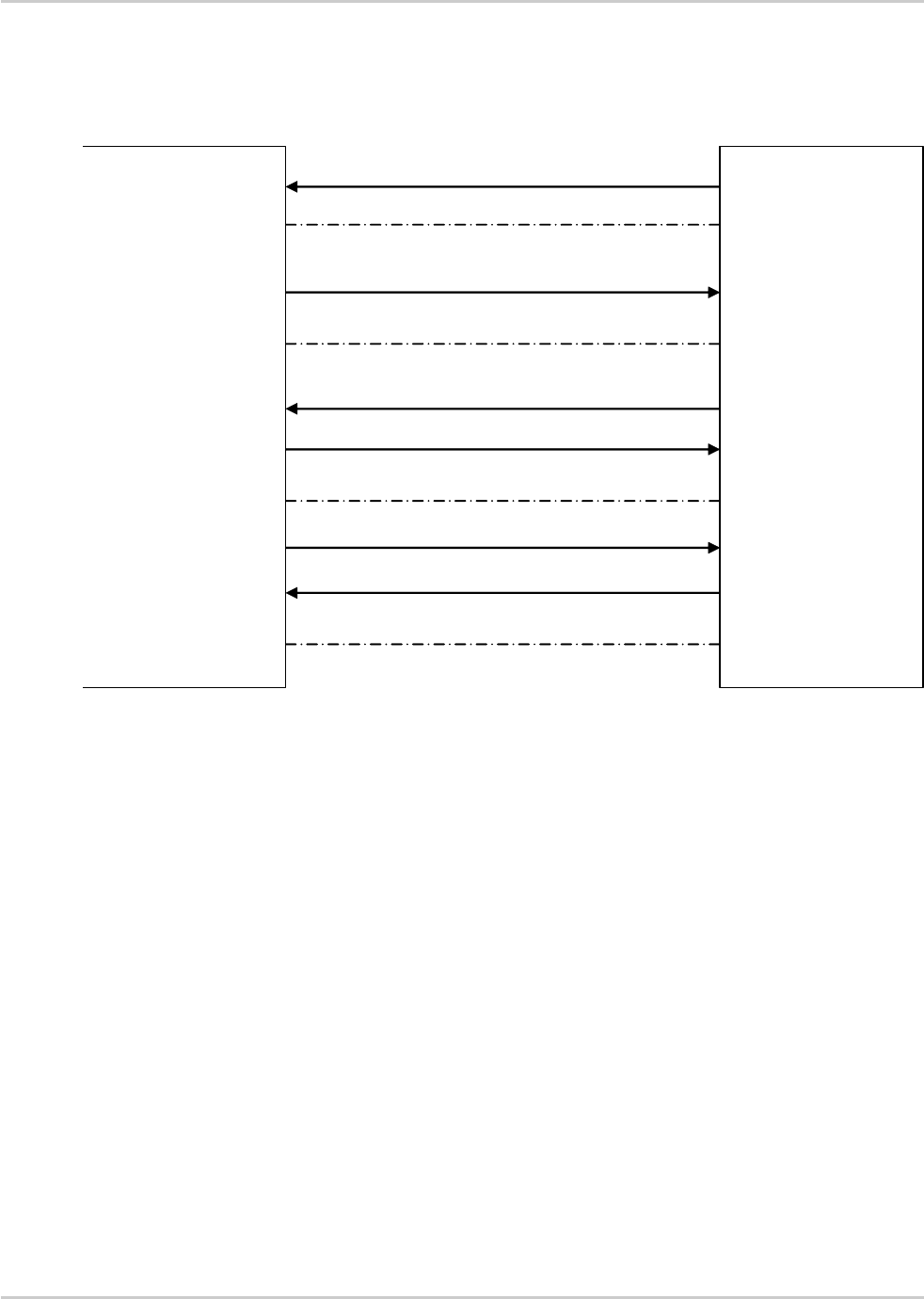
AT Commands Interface Guide for
Firmware 7.52
Error! Use the Home tab to apply Titre 1 to the text that you want
to appear here.
Error! Use the Home tab to apply Titre 2 to the text that you want
to appear here.
Rev. 1.0 Volume 3 March 7, 2014 139
19.1.8. Messages exchanged during a SIM ToolKit
operation
The following figure shows the SIM ToolKit commands and unsolicited results that are exchanged.
SIERRA WIRELESS
Embedded Module
Customer
Application
AT+STSF=X,XXXXXXXX
+STIN: X
AT+STGI=X
+STGI response
AT+STGR=X,XXXXXX
STEP 1: Configuration and Activation
STEP 2: SIM sends proactive
command
STEP 3: Customer application gets all the
information.
Step 4: User response is sent to the SIM.
+STCR: X
On the first step, the customer application informs the Sierra Wireless product which facilities are
supported. This operation is performed with the +STSF (SIM ToolKit Set Facilities) command, which
also allows to activate or deactivate the SIM ToolKit functionality.
On the second step, an unsolicited result +STIN (SIM ToolKit indication) is sent by the product,
indicating to the customer application which command type the SIM Application ToolKit is running on
the SIM card. The last SIM ToolKit indication can be requested by the AT+STIN? command.
On the third step, the customer application uses the +STGI (SIM ToolKit Get Information) command to
get all the information about the SIM ToolKit command, returned by a +STIN message.
On the fourth step, the customer application uses the +STGR (SIM ToolKit Give Response) to send
its response (if any) to the SIM ToolKit Application.
The +STCR (SIM ToolKit Control response) indication is an unsolicited result sent by the SIM when
Call control functionality is activated and before the customer application has performed any outgoing
call, SMS, SS, or USSD.

AT Commands Interface Guide for
Firmware 7.52
Error! Use the Home tab to apply Titre 1 to the text that you want
to appear here.
Error! Use the Home tab to apply Titre 2 to the text that you want
to appear here.
Rev. 1.0 Volume 3 March 7, 2014 140
19.2. SIM ToolKit Set Facilities +STSF
19.2.1. Description
This Sierra Wireless proprietary command allows SIM ToolKit facilities to be activated, deactivated or
configured.
The activation or deactivation of the SIM ToolKit functionalities requires the use of the +CFUN (Set
phone functionality) command to reset the product. This operation is not necessary if PIN is not
entered yet.
19.2.2. Syntax
Action command
AT+STSF=<mode>[,[<Config>][,[<Timeout>][,<AutoMode>]]]
OK
Read command
AT+STSF?
+STSF: <mode>,<Config>,<Timeout>,<AutoMode>
OK
Test command
AT+STSF=?
+STSF: (list of supported <mode>s),(list of supported <Config>s),
(list of supported <Timeout>s),(list of supported <AutoMode>s)
OK

AT Commands Interface Guide for
Firmware 7.52
Error! Use the Home tab to apply Titre 1 to the text that you want
to appear here.
Error! Use the Home tab to apply Titre 2 to the text that you want
to appear here.
Rev. 1.0 Volume 3 March 7, 2014 141
19.2.3. Parameters and Defined Values
<mode>:
SIM ToolKit functionalities activation mode
0
deactivates the SIM ToolKit functionalities.
1
activates the SIM ToolKit functionalities (default value)
2
configures the SIM ToolKit functionalities.
<Config>:
SIM ToolKit terminal profile
This parameter gives the list of the SIM Application ToolKit facilities that are
supported by the customer application.
Some bits of the first nine bytes are related to the product only and not to the
customer application. The product automatically sets these bits to either 0 or 1
whatever the user enters with the +STSF command.
Each facility is coded on 1 bit:
bit = 1: facility is supported by the customer application.
bit = 0: facility is not supported by the customer application.
Please refer to section "Structure of Terminal Profile" in the Appendixes for more
information.
range: 320060C01F0100471C-FFFFFFFF7F01005F3E
default value: 3F6BFFFF1F0100573E
<Timeout>:
timeout for user responses (in units of 10 seconds).
This parameter sets the maximum time for the user action (e.g. to select an item or to
input a text).
range: 1-255 (default value:1)
Note: AirPrime SL808xT and Q2698 modules: 12.
<AutoMode>:
automatic modes; auto response and silent mode
When autoresponse is activated, the +STIN indication for "Play Tone", "Display
Text", "Refresh", "Send SS", "Send SMS" or "Send USSD" is automatically followed
by the corresponding +STGI response.
When the silent mode is activated, the autoresponse mode is activated and no +STIN
and no +STGI indications are returned by the embedded module
0
no auto mode activated
1
auto response mode activated
2
silent mode activated (default value)
19.2.4. Parameter Storage
All parameters are stored in EEPROM without using AT&W.

AT Commands Interface Guide for
Firmware 7.52
Error! Use the Home tab to apply Titre 1 to the text that you want
to appear here.
Error! Use the Home tab to apply Titre 2 to the text that you want
to appear here.
Rev. 1.0 Volume 3 March 7, 2014 142
19.2.5. Examples
Command
Responses
AT+STSF=?
Note: Test command SIM ToolKit Set Facilities
+STSF: (0-2),(320060C01F0100471C-
FFFFFFFF7F01005F3E)),(1-255),(0-2)
OK
AT+STSF?
+STSF: 0," 1F6BFFFF1F0100573E ",3,2
Note: No activation of SIM ToolKit functionality
AT+STSF=2, "FFFFFFFF7F01005F3E",,0
Note: Set all SIM ToolKit facilities (class 3).
OK
AT+STSF=1
Note: Activation of SIM ToolKit functionality
OK
AT+CFUN=1
OK
Note: Reboot embedded module.
AT+STSF?
+STSF: 1,"FFFFFFFF7F01005F3E",3,0
OK
Note: SIM ToolKit functionality activated with all facilities
Notes
Note: For AirPrime SL808xT and Q2698 embedded modules, the new mode is taken into account with the
next reset.

AT Commands Interface Guide for
Firmware 7.52
Error! Use the Home tab to apply Titre 1 to the text that you want
to appear here.
Error! Use the Home tab to apply Titre 2 to the text that you want
to appear here.
Rev. 1.0 Volume 3 March 7, 2014 143
19.3. SIM ToolKit Indication +STIN
19.3.1. Description
This Sierra Wireless proprietary command allows the customer application to identify the proactive
command sent via a mechanism of unsolicited SIM ToolKit indications.
The last SIM ToolKit indication sent by the SIM can be requested by the AT+STIN? command. This
command is only usable between the sending of the STIN indication by the SIM (see UMessages
exchanged during a SIM ToolKit operationU step 2) and the response of the user with the +STGI
command.
19.3.2. Syntax
Action command
None
Read command
AT+STIN?
+STIN: <CmdType>
OK
Test command
AT+STIN=?
OK
Unsolicited response
+STIN: <CmdType>

AT Commands Interface Guide for
Firmware 7.52
Error! Use the Home tab to apply Titre 1 to the text that you want
to appear here.
Error! Use the Home tab to apply Titre 2 to the text that you want
to appear here.
Rev. 1.0 Volume 3 March 7, 2014 144
19.3.3. Parameters and Defined Values
<CmdType>:
type of proactive command or error sent by the SIM
0
"Setup Menu"
1
"Display Text"
2
"Get Inkey"
3
"Get Input"
4
"Setup Call"
5
"Play Tone" (*)
6
"Sel Item"
7
"Refresh" (*)
8
"Send SS" (*)
9
"Send SMS" (*)
10
"Send USSD" (*)
11
"SETUP EVENT LIST"
12
a "SET UP IDLE MODE TEXT"
13
a "SEND DTMF"
14
a "LANGUAGE NOTIFICATION"
93
"SMS-PP Data Download" failed due to SIM BUSY
94
"SMS-PP Data Download" failed due to SIM ERROR
98
timeout when no response from user
99
"End Session"
(*)if the automatic response parameter is activated, this indication is followed by the corresponding
+STGI response.
19.3.4. Parameter Storage
None.

AT Commands Interface Guide for
Firmware 7.52
Error! Use the Home tab to apply Titre 1 to the text that you want
to appear here.
Error! Use the Home tab to apply Titre 2 to the text that you want
to appear here.
Rev. 1.0 Volume 3 March 7, 2014 145
19.3.5. Examples
Command
Responses
+STIN: 0
Note: "Setup Menu" proactive command has been sent by the SIM.
AT+STIN?
Note: Ask for the last SIM ToolKit indication sent by
the SIM
+STIN: 0
OK
Note: The last SIM ToolKit indication was a "Setup Menu"
AT+STGI=0
+STGI: "Toolkit Menu"+STGI: 1,4,"Item 1",0
+STGI: 2,4,"Item 2",0
OK
+STGI: 99
Note: Display the SIM ToolKit application menu
AT+STIN?
Note: Ask for the last SIM ToolKit indication sent by
the SIM
+CME ERROR: 4
Note: Operation not supported, the +STGI command has been
already used

AT Commands Interface Guide for
Firmware 7.52
Error! Use the Home tab to apply Titre 1 to the text that you want
to appear here.
Error! Use the Home tab to apply Titre 2 to the text that you want
to appear here.
Rev. 1.0 Volume 3 March 7, 2014 146
19.4. SIM ToolKit Get Information +STGI
19.4.1. Description
This Sierra Wireless proprietary command allows to get the information (e.g. text to display, menu
information, priorities…) of a proactive command sent by the SIM.
The information is returned only after receiving a SIM ToolKit indication (+STIN).
19.4.2. Syntax
Depending on the value of the <CmdType> parameter several response syntaxes are available:
For <CmdType>=0: get information about "Setup Menu" (No action expected from SIM).
Action command
AT+STGI=<CmdType>
+STGI: <Alpha Identifier menu>
+STGI: <Id>,<NbItems>,<AlphaId Label>,<HelpInfo>[,<NextActionId>]
[+STGI: <Id>,<NbItems>,<AlphaId Label>,<HelpInfo>[,<NextActionId>]
[…]]
OK
For <CmdType>=1: get information about "Display Text" (No action expected from SIM).
Action command
AT+STGI=<CmdType>
+STGI: <Prior>,<Text>,<ClearMode>
OK
For <CmdType>=2: get information about "Get Inkey" (SIM expects key pressed sent using
+STGR)
Action command
AT+STGI=<CmdType>
+STGI: <InkeyFormat>,<HelpInfo>[,<TextInfo>]
OK

AT Commands Interface Guide for
Firmware 7.52
Error! Use the Home tab to apply Titre 1 to the text that you want
to appear here.
Error! Use the Home tab to apply Titre 2 to the text that you want
to appear here.
Rev. 1.0 Volume 3 March 7, 2014 147
For <CmdType>=3: get information about ‘"Get Input" (SIM expects key input sent using
+STGR)
Action command
AT+STGI=<CmdType>
+STGI:
<InputFormat>,<EchoMode>,<SizeMin>,<SizeMax>,<HelpInfo>[,<TextInfo>,
<DefaultText>]
OK
For <CmdType>=4: get information about "Setup Call" (If <Class> is omitted, call is
processed as a voice call)
Action command
AT+STGI=<CmdType>
+STGI: <Type>,<CalledNb>,<SubAddress>,<Class>,<AlphaId>,<AlphaId2>
OK
For <CmdType>=5: get information about "Play Tone" (No action)
Action command
AT+STGI=<CmdType>
+STGI: <ToneType>[,<TimeUnit>,<TimeInterval>,<TextInfo>]
OK
For <CmdType>=6: get information about "Sel Item" (SIM expects an item choice sent using
+STGR)
Action command
AT+STGI=<CmdType>
+STGI: <PresetStyle>,<PresetChoice>,<DefaultItem>, <Alpha Identifier menu>
+STGI: <Id>,<NbItems>,<AlphaId Label>,<HelpInfo>[,<NextActionId>]
[+STGI: <Id>,<NbItems>,<AlphaId Label>,<HelpInfo>[,<NextActionId>]
[…]]
OK
For <CmdType>=7: get information about "Refresh" (No action, "Refresh" done automatically
by product).
Action command
AT+STGI=<CmdType>
+STGI: <RefreshType>
OK

AT Commands Interface Guide for
Firmware 7.52
Error! Use the Home tab to apply Titre 1 to the text that you want
to appear here.
Error! Use the Home tab to apply Titre 2 to the text that you want
to appear here.
Rev. 1.0 Volume 3 March 7, 2014 148
For <CmdType>=8: get information about "Send SS" (No action, "Send SS" done
automatically by product).
Action command
AT+STGI=<CmdType>
+STGI: <TextInfo>
OK
For <CmdType>=9: get information about "Send SMS" (No action, "Send SMS" done
automatically by product).
Action command
AT+STGI=<CmdType>
+STGI: <TextInfo>
OK
For <CmdType>=10: get information about "Send USSD" proactive command. (No action,
"Send USSD" done automatically by product)
Action command
AT+STGI=<CmdType>
+STGI: <TextInfo>
OK
For <CmdType>=11: get information about "Setup Event List".
Action command
AT+STGI=<CmdType>
+STGI: <Evt>
OK
For <CmdType>=12: get information about "Setup Idle Mode Text".
Action command
AT+STGI=<CmdType>
+STGI: <Text>
OK
For <CmdType>=13: get information about "Send DTMF".
Action command
AT+STGI=<CmdType>
+STGI: <TextInfo>
OK

AT Commands Interface Guide for
Firmware 7.52
Error! Use the Home tab to apply Titre 1 to the text that you want
to appear here.
Error! Use the Home tab to apply Titre 2 to the text that you want
to appear here.
Rev. 1.0 Volume 3 March 7, 2014 149
For <CmdType>=14: get information about "Language Notification".
Action command
AT+STGI=<CmdType>
+STGI: <Specific>[,<Code>]
OK
Read command
None
Test command
AT+STGI=?
+STGI: (list of supported <CmdType>s)
OK
19.4.3. Parameters and Defined Values
<Alpha Identifier menu>:
alpha identifier of the main menu
string type
<Id>:
menu item Identifier
range: 1-255
<NbItems>:
number of items in the main menu
range: 1-255
<AlphaId Label>:
alpha identifier label of items
string type (ASCII format)
<HelpInfo>:
help information availability
0
not available
1
available
<NextActionId>:
next proactive command identifier
integer type
<Prior>:
display priority

AT Commands Interface Guide for
Firmware 7.52
Error! Use the Home tab to apply Titre 1 to the text that you want
to appear here.
Error! Use the Home tab to apply Titre 2 to the text that you want
to appear here.
Rev. 1.0 Volume 3 March 7, 2014 150
0
normal
1
high
<Text>:
text to display
string type (ASCII format)
<ClearMode>:
message clearing mode
0
clear message after a delay (3 seconds)
1
wait for user to clear message
<InkeyFormat>:
"Get Inkey" format
0
Digit (0-9, *, #,and +)
1
SMS alphabet default
2
UCS2
3
Yes/No (y and n)
<Textinfo>:
text information
string type (ASCII format)
<InputFormat>:
"Get Input" format
0
digit (0-9, *, #,and +)
1
SMS alphabet default
2
UCS2
3
unpacked format
4
packed format
<EchoMode>:
echo mode
0
off
1
on
<SizeMin>:
minimum length of input
range: 1-255
<SizeMax>:
maximum length of input
range: 1-255
<DefaultText>:
default input text
string type (ASCII format)
<Type>:
call behaviour

AT Commands Interface Guide for
Firmware 7.52
Error! Use the Home tab to apply Titre 1 to the text that you want
to appear here.
Error! Use the Home tab to apply Titre 2 to the text that you want
to appear here.
Rev. 1.0 Volume 3 March 7, 2014 151
0
set up call but only if not currently busy on another call
1
set up call, putting all other calls (if any) on hold
2
set up call, disconnecting all other calls (if any)
<CalledNb>:
called party number
string type (ASCII format)
<SubAdress>:
called party sub-address
string type (ASCII format)
<Class>:
call class
0
voice call
1
data call
2
fax call
<Alpha Id>:
text information for user confirmation phase
string type (ASCII format)
<Alpha Id2>:
text information for call set-up phase and calling phase
string type (ASCII format)
<ToneType>:
tone type
0
dial
1
busy
2
congestion
3
radio ack
4
dropped
5
error
6
call waiting
7
ringing
8
general beep
9
positive beep.
10
negative beep.
<TimeUnit>:
time unit for < TimeInterval>
0
minutes
1
seconds

AT Commands Interface Guide for
Firmware 7.52
Error! Use the Home tab to apply Titre 1 to the text that you want
to appear here.
Error! Use the Home tab to apply Titre 2 to the text that you want
to appear here.
Rev. 1.0 Volume 3 March 7, 2014 152
2
tenths of seconds
<TimeInterval>:
time required for tone playing expressed in <TimeUnit>
range: 1-255
<PresentStyle>:
presentation type
0
unspecified
1
specified in <PresentChoice>
<PresentChoice>:
presentation choice for <PresentStyle>=1
0
choice of data values
1
choice of navigation options
<DefaultItem>:
default item identifier
range: 1-255
<RefreshType>:
refresh type
0
SlM initialization and full file change notification
1
file change notification
2
SIM initialization and file change notification
3
SIM initialization
4
SIM reset
<Evt>:
setup event list
1
reporting asked for "Idle Screen"
2
reporting asked for "User Activity"
3
reporting asked for "Idle Screen" and "User Activity"
4
cancellation of reporting event
<Specific>:
language notification type
0
non specific
1
specific
<Code>:
2 character code for the language
The number indicated after the name refers to numeric value for the language in
ISO 639 U[16]U.
If non-specific, no <Code> will be defined.
See UNotesU for UCS2 format texts.
"de"
German (0)

AT Commands Interface Guide for
Firmware 7.52
Error! Use the Home tab to apply Titre 1 to the text that you want
to appear here.
Error! Use the Home tab to apply Titre 2 to the text that you want
to appear here.
Rev. 1.0 Volume 3 March 7, 2014 153
"en"
English (1)
"it"
Italian (2)
fr"
French (3)
"es"
Spanish (4)
"nl "
Dutch (5)
"sv"
Swedish (6)
"da"
Danish (7)
"pt"
Portuguese (8)
"fi"
Finnish (9)
"no"
Norwegian (10)
"el"
Greek (11)
"tr"
Turkish (12)
"hu"
Hungarian (13)
"pl"
Polish (14)
"cs"
Czech (32)
"he"
Hebrew (33)
"ar"
Arabic (34)
"ru"
Russian (35)
"is"
Icelandic (36)
19.4.4. Parameter Storage
None.
19.4.5. Examples
Command
Responses
+STIN: 0
Note: "Setup Menu" proactive command has been sent by the SIM.

AT Commands Interface Guide for
Firmware 7.52
Error! Use the Home tab to apply Titre 1 to the text that you want
to appear here.
Error! Use the Home tab to apply Titre 2 to the text that you want
to appear here.
Rev. 1.0 Volume 3 March 7, 2014 154
Command
Responses
AT+STGI=0
+STGI: "SIM TOOLKIT MAIN MENU"
+STGI: 1,3,"BANK",0
+STGI: 2,3,"QUIZ",0
+STGI: 3,3,"WEATHER",0
OK
Note:Get information about the main menu
Note: Main menu contains 3 items
19.4.6. Notes
For the UCS2 format, texts are displayed in Hexa ASCII format. Example: when the SIM sends a
TextString containing 0x00 0x41, the text displayed is "0041". (For details see section "3.6 Coding of
Alpha fields in the SIM for UCS2" of the Appendixes)

AT Commands Interface Guide for
Firmware 7.52
Error! Use the Home tab to apply Titre 1 to the text that you want
to appear here.
Error! Use the Home tab to apply Titre 2 to the text that you want
to appear here.
Rev. 1.0 Volume 3 March 7, 2014 155
19.5. SIM ToolKit Give Response +STGR
19.5.1. Description
This command allows the application/user to select an item in the main menu, or to answer the
following proactive commands:
GET INKEY
key pressed by the user
GET INPUT
message entered by the user
SELECT ITEM
selected item
SETUP CALL
user confirmation
DISPLAY TEXT
user confirmation to clear the message
SETUP EVENT LIST
reporting events
SETUP IDLE MODE TEXT
reporting events
It is also possible to terminate the current proactive command session by sending a Terminal
Response to the SIM, with the following parameters:
BACKWARD MOVE
process a backward move
BEYOND CAPABILITIES
command beyond ME capabilities
UNABLE TO PROCESS
ME is currently unable to process
NO RESPONSE
no response from the user
END SESSION
user abort
19.5.2. Syntax
Action command
AT+STGR=<CmdType>[,<Result>[,<Data>]]
[> <input text> <ctrl-Z/ESC>]
OK
Read command
None

AT Commands Interface Guide for
Firmware 7.52
Error! Use the Home tab to apply Titre 1 to the text that you want
to appear here.
Error! Use the Home tab to apply Titre 2 to the text that you want
to appear here.
Rev. 1.0 Volume 3 March 7, 2014 156
Test command
AT+STGR=?
OK
19.5.3. Parameters and Defined Values
<CmdType>:
command type
0
item selection in the main menu
1
user confirmation to clear a "DISP TEXT"
2
response for a "GET INKEY"
3
response for a "GET INPUT"
4
response for a "SETUP CALL"
6
response for a "SEL ITEM"
11
response for a "SETUP EVENT LIST"
12
response for a "SETUP IDLE MODE TEXT"
95
send "BACKWARD MOVE" to SIM
96
send "BEYOND CAPABILITIES" to SIM
97
send "UNABLE TO PROCESS" to SIM
98
send "NO RESPONSE" to SIM
99
send "END SESSION" to SIM
Values when <CmdType>=0 (Select an item from the main menu)
<Result>:
user action
1
item selected by the user
2
help information required by user
<Data>:
item identifier of the item selected by the user
integer type
Values when <CmdType>=1 (Select an item from the main menu)
None.

AT Commands Interface Guide for
Firmware 7.52
Error! Use the Home tab to apply Titre 1 to the text that you want
to appear here.
Error! Use the Home tab to apply Titre 2 to the text that you want
to appear here.
Rev. 1.0 Volume 3 March 7, 2014 157
Values when <CmdType>=2 (GET INKEY, see UNotesU)
<Result>:
user action
0
session ended by user
1
response given by the user
2
help information required by user
<Data>:
key pressed by the user
string type
Values when <CmdType>=3 (GET INPUT, see UNotesU)
<Result>:
user action
0
session ended by user
1
response given by the user
2
help information required by user
<input text>:
text sent by user
string type
Values when <CmdType>=4 (SETUP CALL)
<Result>:
user action
0
user refuses the call
1
user accepts call
2
user accepts call; call is started by applicative software
AirPrime SL808xT and Q2698 modules: This user action is not supported.
Values when <CmdType>=6 (SELECT ITEM)
<Result>:
user action

AT Commands Interface Guide for
Firmware 7.52
Error! Use the Home tab to apply Titre 1 to the text that you want
to appear here.
Error! Use the Home tab to apply Titre 2 to the text that you want
to appear here.
Rev. 1.0 Volume 3 March 7, 2014 158
0
session terminated by the user
1
Item selected by the user
2
help information required by the user
3
return to the back item
<Data>:
item identifier selected by the user
integer type
Values when <CmdType>=11 (SETUP EVENT LIST)
<Result>:
user action
1
user selects idle screen
2
user selects user activity
Values when <CmdType>=12 (SETUP IDLE MODE TEXT)
<Result>:
user action
0
user successfully integrates the idle mode text
1
user is not able to successfully integrate the idle mode text
For all other cases, no values are needed.
19.5.4. Parameter Storage
None.
19.5.5. Examples
Command
Responses
+STIN: 0
Note: The main menu has been sent from the SIM.
AT+STGI=0
+STGI: 1,3,"BANK",0
+STGI: 2,3,"QUIZ",0
+STGI: 3,3,"WEATHER",0
OK

AT Commands Interface Guide for
Firmware 7.52
Error! Use the Home tab to apply Titre 1 to the text that you want
to appear here.
Error! Use the Home tab to apply Titre 2 to the text that you want
to appear here.
Rev. 1.0 Volume 3 March 7, 2014 159
Command
Responses
Note: Get information about the main menu
Note:The main menu contains 3 items
AT+STGR=0,1,1
OK
+STIN: 6
Note: The item 2 of the main menu has been selected.
+STIN: 4
AT+STGI=4
+STGI: 0,"0146290800","",0
OK
AT+STGR=4,2
OK
ATD0146290800
OK
+STIN: 99
AT+STGI=6
Note: Get information about the BANK menu
+STGI: 1,"BANK"
+STGI: 1,2,"PERSONAL ACCOUNT ENQUIRY",1
+STGI: 2,2,"NEWS",0
OK
Note: The BANK menu contains two items.
AT+STGR=6,1,1
OK
Note: Select Item 1
+STIN: 99
Note: End of session
19.5.6. Notes
For a GET INKEY with format set to "Yes/No", the data shall contain:
the value "y" when the answer is "positive",
the value "n" when the answer is "negative".
For inputs in UCS2 format, the data are entered in ASCII format.
Example: For "8000410042FFFF" entered, the SIM receives 0x00 0x41 0x00 0x42 with UCS2
DCS. (about the different UCS2 syntaxes, please refer to section "Coding of Alpha fields in
the SIM for UCS2" of the Appendixes to AT Commands Interface Guide).
Comments upon Terminal Responses:
For the SETUP MENU Proactive Command, it is only possible to send a Terminal
Response after the "+STIN: 0" indication, not after a "AT+STGI=0" request. For the other
Proactive Commands, it is possible to send a Terminal Response after the "+STIN"
indication or after the "+STGI" command.
All of the Terminal Responses are not possible with all of the Proactive Commands.
Compatibility between available Terminal Responses and Proactive Commands is given

AT Commands Interface Guide for
Firmware 7.52
Error! Use the Home tab to apply Titre 1 to the text that you want
to appear here.
Error! Use the Home tab to apply Titre 2 to the text that you want
to appear here.
Rev. 1.0 Volume 3 March 7, 2014 160
in section "Support of SIM ToolKit by the M.E." of the Appendixes to AT Commands
Interface Guide. If a Terminal Response is attempted during a incompatible Proactive
Command session, a "+CME ERROR: 3" will be returned.
If AT+STGR=4,2 command is sent to confirm a STK Setup Call, the applicative software must
send the ATD command (using the call number given by AT+STGI=4 command) within a
timeout value to define (check existing internal STK timeouts).

AT Commands Interface Guide for
Firmware 7.52
Error! Use the Home tab to apply Titre 1 to the text that you want
to appear here.
Error! Use the Home tab to apply Titre 2 to the text that you want
to appear here.
Rev. 1.0 Volume 3 March 7, 2014 161
19.6. SIM ToolKit Control Response +STCR
19.6.1. Description
This Sierra Wireless proprietary unsolicited response allows the customer application to identify "Call
Control" and "SMS Control" responses when an outgoing call is initiated or an outgoing SMS is sent
and the call control facility is activated. This is also applicable to SS calls.
19.6.2. Syntax
Action command
None
Read command
None
Test command
None
Unsolicited response
+STCR: <Result>[,<Number>,<MODestAddr>,<TextInfo>]
19.6.3. Parameters and Defined Values
<Result>:
SIM response to the operation
0
control response not allowed
1
control response with modification
<Number>:
called number, Service Center Address or SS String
string type (ASCII format)
<MODestAddr>:
MO destination address
string type (ASCII format)

AT Commands Interface Guide for
Firmware 7.52
Error! Use the Home tab to apply Titre 1 to the text that you want
to appear here.
Error! Use the Home tab to apply Titre 2 to the text that you want
to appear here.
Rev. 1.0 Volume 3 March 7, 2014 162
<TextInfo>:
text information
string type (ASCII format)
19.6.4. Parameter Storage
None.
19.6.5. Examples
Command
Responses
+STIN: 9
Note: "Send SMS" proactive command has been sent by the SIM.
AT+STGI=9
Note: get information about "Send SMS”
+STGI: "Send SM"
+STCR: 1,"+112233445566779","+012345679"
OK
Note: The “Send SMS” was allowed with modifications. The SC
address was changed from +012345679 to +112233445566779
+STIN: 99
Note: End of session

AT Commands Interface Guide for
Firmware 7.52
Error! Use the Home tab to apply Titre 1 to the text that you want
to appear here.
Error! Use the Home tab to apply Titre 2 to the text that you want
to appear here.
Rev. 1.0 Volume 3 March 7, 2014 163
19.7. SIM ToolKit Indication +STRIL
19.7.1. Description
This Sierra Wireless proprietary command allows the customer application to exchange SIM ToolKit
messages directly with the SIM card, using the unsolicited indication +STRIL to get the full command
string.
19.7.2. Syntax
Action command
None
Read command
None
Test command
None
Unsolicited response
+STRIL: <CmdTreated>,<Command string>

AT Commands Interface Guide for
Firmware 7.52
Error! Use the Home tab to apply Titre 1 to the text that you want
to appear here.
Error! Use the Home tab to apply Titre 2 to the text that you want
to appear here.
Rev. 1.0 Volume 3 March 7, 2014 164
19.7.3. Parameters and Defined Values
<CmdTreated>:
0
the command must be treated by the application
1
the command is already treated by the embedded module
<Command string>:
SIM command string in hexadecimal format
string type
19.7.4. Parameter Storage
None.

Rev. 1.0 Volume 3 March 7, 2014 165
20. Supplementary Services
Commands
20.1. List Current Calls +CLCC
20.1.1. Description
This command is used to return the list of current calls.
20.1.2. Syntax
Action command
AT+CLCC
[+CLCC: <id>,<dir>,<stat>,<mode>,<mpty>[,<number>,<type>[,<alpha>]]][…]
OK
Read command
AT+CLCC?
OK
Test command
AT+CLCC=?
OK

AT Commands Interface Guide for
Firmware 7.52
Error! Use the Home tab to apply Titre 1 to the text that you want
to appear here.
Error! Use the Home tab to apply Titre 2 to the text that you want
to appear here.
Rev. 1.0 Volume 3 March 7, 2014 166
20.1.3. Parameters and Defined Values
<id>:
call identification
integer type
range: 1-7
<dir>:
call direction
0
mobile originated (MO) call
1
mobile terminated (MT) call
<stat>:
call state
0
active
1
held
2
dialing (MO call)
3
alerting (MO call)
4
incoming call (MT call)
5
waiting call (MT call)
<mode>:
teleservice
0
voice
1
data
2
fax
9
unknown
<mpty>:
multiparty
0
call is not one of multiparty (conference) call parties
1
call is one of multiparty (conference) call parties
<number>:
phone number in format specified by <type>
string type
<type>:
TON/NPI Type of address octet (refer GSM 04.08 subclause 10.5.4.7 U[6]U)
integer type

AT Commands Interface Guide for
Firmware 7.52
Error! Use the Home tab to apply Titre 1 to the text that you want
to appear here.
Error! Use the Home tab to apply Titre 2 to the text that you want
to appear here.
Rev. 1.0 Volume 3 March 7, 2014 167
129
ISDN / telephony numbering plan, national / international unknown
145
ISDN / telephony numbering plan, international number
161
ISDN / telephony numbering plan, national number
128-255
other values (refer GSM 04.08 section 10.5.4.7 U[6]U)
<alpha>:
phonebook number entry
optional alphanumeric representation of <number>, corresponding to the
entry found in phonebook. (for UCS2 format see commands examples
U+CLIPU, U+CCWAU or U+COLPU)
string type
20.1.4. Parameter Storage
None.
20.1.5. Examples
Command
Responses
RING
Note: Incoming call
AT+CLCC
+CLCC: 1,1,4,0,0,"0123456789",129
OK
ATA
OK
Note: Answering the call
AT+CLCC
+CLCC: 1,1,1,0,0,"0123456789",129
OK
ATH
Note: Releasing the call
OK
ATD0123456789;
Note: Outgoing call
AT+CLCC
+CLCC: 1,0,2,0,0,"0123456789",129
Note: Before the called party is ringing
OK
AT+CLCC
+CLCC: 1,0,3,0,0,"0123456789",129
Note: The called party is ringing
OK

AT Commands Interface Guide for
Firmware 7.52
Error! Use the Home tab to apply Titre 1 to the text that you want
to appear here.
Error! Use the Home tab to apply Titre 2 to the text that you want
to appear here.
Rev. 1.0 Volume 3 March 7, 2014 168
Command
Responses
OK
Note: Response to dial command
AT+CLCC
+CLCC: 1,0,0,0,0,"0123456789",129
Note: The call is being answered
OK

AT Commands Interface Guide for
Firmware 7.52
Error! Use the Home tab to apply Titre 1 to the text that you want
to appear here.
Error! Use the Home tab to apply Titre 2 to the text that you want
to appear here.
Rev. 1.0 Volume 3 March 7, 2014 169
20.2. Call Related Supplementary Services +CHLD
20.2.1. Description
This command is used to manage call hold and multiparty conversation (conference call). Calls can
be put on hold, recovered, released or added to a conversation.
Call hold and multiparty are only applicable to teleservice 11 (speech telephony).
20.2.2. Syntax
Action command
AT+CHLD=<n>
OK
Read command
AT+CHLD?
OK
Test command
AT+CHLD=?
+CHLD: (list of supported <n>s)
OK

AT Commands Interface Guide for
Firmware 7.52
Error! Use the Home tab to apply Titre 1 to the text that you want
to appear here.
Error! Use the Home tab to apply Titre 2 to the text that you want
to appear here.
Rev. 1.0 Volume 3 March 7, 2014 170
20.2.3. Parameters and Defined Values
<n>:
call related services
0
release all held calls or set User Determined User Busy (UDUB) for a waiting call.
1
release all active calls (if any exist) and accepts the other (held or waiting) call.
1X
release a specific call X (active, held or waiting).
2
place all active calls (if any exist) on hold and accepts the other (held or waiting)
call.
2X
place all active calls on hold except call X with which communication is
supported.
3
add a held call to the conversation.
4
connect the two calls and disconnect the subscriber from both calls (Explicit Call
Transfer).
20.2.4. Parameter Storage
None.
20.2.5. Examples
Command
Responses
AT+CHLD=?
+CHLD: (0-4,11-17,21-27)
OK
ATD0123456789;
OK
+WIND: 5,1
AT+CLCC
+CLCC: 1,0,0,0,0,"0123456789",129
OK
+WIND: 5,2
Note: incoming call in waiting state
AT+CLCC
Note: Com id 1 is active, com id 2 is in waiting state
+CLCC: 1,0,0,0,0,"0123456789",129
+CLCC: 2,1,5,0,0
OK
AT+CHLD=2
OK

AT Commands Interface Guide for
Firmware 7.52
Error! Use the Home tab to apply Titre 1 to the text that you want
to appear here.
Error! Use the Home tab to apply Titre 2 to the text that you want
to appear here.
Rev. 1.0 Volume 3 March 7, 2014 171
Command
Responses
AT+CLCC
+CLCC: 1,0,1,0,0,"0123456789",129
+CLCC: 2,1,0,0,0
OK
Note: Com id 1 is held, com id 2 is active
20.2.6. Notes
For AirPrime SL808xT: The command may answer “+CME ERROR: 3 if a waiting call is being
disconnected using the “AT+CHLD=1X” command.

AT Commands Interface Guide for
Firmware 7.52
Error! Use the Home tab to apply Titre 1 to the text that you want
to appear here.
Error! Use the Home tab to apply Titre 2 to the text that you want
to appear here.
Rev. 1.0 Volume 3 March 7, 2014 172
20.3. Calling Line Identification Presentation +CLIP
20.3.1. Description
This command enables the Calling Line Identification Presentation supplementary service. When
presentation of the CLI is enabled (and the calling subscriber allows the function), +CLIP unsolicited
response is returned after every RING (or +CRING) result code.
20.3.2. Syntax
Action command
AT+CLIP=<n>
OK
Read command
AT+CLIP?
+CLIP: <n>,<m>
OK
Test command
AT+CLIP=?
+CLIP: (list of supported <n>s)
OK
Unsolicited response
+CLIP: <number>,<type>[,<subaddr>,<satype>[,[<alpha>][,<CLI validity>]]]

AT Commands Interface Guide for
Firmware 7.52
Error! Use the Home tab to apply Titre 1 to the text that you want
to appear here.
Error! Use the Home tab to apply Titre 2 to the text that you want
to appear here.
Rev. 1.0 Volume 3 March 7, 2014 173
20.3.3. Parameters and Defined Values
<n>:
CLIP mode in the TA
0
disable (default value)
1
enable
<m>:
subscriber CLIP service status in the network
0
CLIP not provisioned
1
CLIP provisioned
2
unknown (no network…)
<number>:
phone number
string type
<type>:
TON/NPI type of address octet for <number>. (refer to GSM 04.08 subclause
10.5.4.7 U[6]U)
integer type
129
ISDN / telephony numbering plan, national / international unknown
<number> does not include the international access code character "+"
145
ISDN / telephony numbering plan, international number
<number> includes the international access code character "+"
161
ISDN / telephony numbering plan, national number
128-255
other values (refer GSM 04.08 section 10.5.4.7 U[6]U)
<subaddr>
not supported
<satype>:
not supported
<alpha>:
phonebook name associated with <number>
string type
<CLI validity>:
not supported
20.3.4. Parameter Storage
The <n> parameter is stored in EEPROM using AT&W command. The default value can be restored
using AT&F.

AT Commands Interface Guide for
Firmware 7.52
Error! Use the Home tab to apply Titre 1 to the text that you want
to appear here.
Error! Use the Home tab to apply Titre 2 to the text that you want
to appear here.
Rev. 1.0 Volume 3 March 7, 2014 174
20.3.5. Examples
Command
Responses
AT+CLIP=1
Note: Enable CLIP
OK
AT+CLIP?
Note: Ask for current functionality
+CLIP:1,1
OK
Note: CLIP is enabled and provisioned
RING
Note: Incoming call
+CLIP: "0146290800",129,1,,"FRED"
Note: Incoming call with number and name presentation
RING
Note: Incoming call
+CLIP: "0146290800",129,1,,"8000204212FFFF"
Note: Incoming call with number and name presentation (UCS2
format)
RING
Note: Incoming call
+CLIP: "0146290800",161
Note: Incoming call not found in any phonebook
AT+CLIP=?
+CLIP: (0-1)
OK

AT Commands Interface Guide for
Firmware 7.52
Error! Use the Home tab to apply Titre 1 to the text that you want
to appear here.
Error! Use the Home tab to apply Titre 2 to the text that you want
to appear here.
Rev. 1.0 Volume 3 March 7, 2014 175
20.4. Calling Line Identification Restriction +CLIR
20.4.1. Description
This command enables the Calling Line Identification Restriction supplementary service.
20.4.2. Syntax
Action command
AT+CLIR=<n>
OK
Read command
AT+CLIR?
+CLIR: <n>,<m>
OK
Test command
AT+CLIR=?
+CLIR: (list of supported <n>s)
OK
20.4.3. Parameters and Defined Values
<n>:
CLIR mode for outgoing calls
0
Presentation indicator is used according to the subscription of the CLIR service.
(default value)
1
CLIR invocation
2
CLIR suppression

AT Commands Interface Guide for
Firmware 7.52
Error! Use the Home tab to apply Titre 1 to the text that you want
to appear here.
Error! Use the Home tab to apply Titre 2 to the text that you want
to appear here.
Rev. 1.0 Volume 3 March 7, 2014 176
<m>:
subscriber CLIR status in the network
0
CLIR not provisioned
1
CLIR provisioned in permanent mode
2
unknown (no network…)
3
CLIR temporary mode presentation restricted
4
CLIR temporary mode presentation allowed
20.4.4. Parameter Storage
The <n> parameter is stored in EEPROM witghout using AT&W command.
20.4.5. Examples
Command
Responses
AT+CLIR=2
OK
AT+CLIR?
Note: Ask for current functionality
+CLIR: 2,4
OK
AT+CLIR=?
+CLIR: (0-2)
OK

AT Commands Interface Guide for
Firmware 7.52
Error! Use the Home tab to apply Titre 1 to the text that you want
to appear here.
Error! Use the Home tab to apply Titre 2 to the text that you want
to appear here.
Rev. 1.0 Volume 3 March 7, 2014 177
20.5. Connected Line Identification Presentation
+COLP
20.5.1. Description
This command enables the COnnected Line identification Presentation supplementary service. This
can be useful for call forwarding of the connected line. When presentation of the connected line
identification is enabled (and the calling subscriber allows the function), +COLP unsolicited response
is returned in response of an ATD command.
20.5.2. Syntax
Action command
AT+COLP=<n>
OK
Read command
AT+COLP?
+COLP: <n>,<m>
OK
Test command
AT+COLP=?
+COLP: (list of supported <n>s)
OK
Unsolicited response
+COLP: <number>,<type>[,<subaddr>,<satype>[,<alpha>]]

AT Commands Interface Guide for
Firmware 7.52
Error! Use the Home tab to apply Titre 1 to the text that you want
to appear here.
Error! Use the Home tab to apply Titre 2 to the text that you want
to appear here.
Rev. 1.0 Volume 3 March 7, 2014 178
20.5.3. Parameters and Defined Values
<n>:
parameter sets/shows the result code presentation status in the TA
0
disable (default value)
1
enable
<m>:
parameter shows the subscriber COLP service status in the network
0
COLP not provisioned
1
COLP provisioned
2
unknown (no network)
<number>:
phone number
string type
<type>:
TON/NPI Type of address octet for <number> (refer GSM 04.08 subclause 10.5.4.7
U[6]U)
integer type
129
ISDN / telephony numbering plan, national / international unknown
<number> does not include the international access code character "+"
145
ISDN / telephony numbering plan, international number
<number> includes the international access code character "+"
161
ISDN / telephony numbering plan, national number
128-255
other values (refer GSM 04.08 section 10.5.4.7 U[6]U)
<subaddr>
subaddress
string type
<satype>:
TON/NPI Type of address octet for <subaddr> (refer GSM 04.08 subclause 10.5.4.7
U[6]U)
integer type
129
ISDN / telephony numbering plan, national / international unknown
<subaddr> does not include the international access code character "+"
145
ISDN / telephony numbering plan, international number
<subaddr> includes the international access code character "+".
161
ISDN / telephony numbering plan, national number
128-255
other values (refer GSM 04.08 section 10.5.4.7 U[6]U)
<alpha>:
phonebook name associated with <number>
string type

AT Commands Interface Guide for
Firmware 7.52
Error! Use the Home tab to apply Titre 1 to the text that you want
to appear here.
Error! Use the Home tab to apply Titre 2 to the text that you want
to appear here.
Rev. 1.0 Volume 3 March 7, 2014 179
20.5.4. Parameter Storage
The <n> parameter is stored in EEPROM using the AT&W command. The default value can be
restored using AT&F.
20.5.5. Examples
Command
Responses
AT+COLP=1
Note: Activate COLP
OK
AT+COLP?
Note: Ask for current functionality
+COLP:1,1
OK
Note: COLP is enabled and provisioned
ATD146290800;
+COLP: "0146290800",129,,"SIERRA WIRELESS"
or
+COLP: "0146290800",129,1,,"8000204212FFFF"
OK
Note: Outgoing call
Note:
"8000204212FFFF": UCS2 format
Connected outgoing line number and name presentation
AT+COLP=?
+COLP: (0-1)
OK

AT Commands Interface Guide for
Firmware 7.52
Error! Use the Home tab to apply Titre 1 to the text that you want
to appear here.
Error! Use the Home tab to apply Titre 2 to the text that you want
to appear here.
Rev. 1.0 Volume 3 March 7, 2014 180
20.6. Supplementary Service Notifications +CSSN
20.6.1. Description
This command allows to configure the supplementary service related network initiated notifications.
20.6.2. Syntax
Action command
AT+CSSN=<n>,<m>
OK
Read command
AT+CSSN?
+CSSN: <n>,<m>
OK
Test command
AT+CSSN=?
+CSSN: (list of supported <n>s),(list of supported <m>s)
OK
Intermediate response
+CSSI: <code1>[,<index>]
Note: +CSSI becomes a unsolicited response in the case of +WBHV: 2,1.
Unsolicited response
+CSSU: <code2>[,<index>[,<number>,<type>]]

AT Commands Interface Guide for
Firmware 7.52
Error! Use the Home tab to apply Titre 1 to the text that you want
to appear here.
Error! Use the Home tab to apply Titre 2 to the text that you want
to appear here.
Rev. 1.0 Volume 3 March 7, 2014 181
20.6.3. Parameters and Defined Values
<n>:
MO supplementary service notification
0
disable (default value)
1
enable
When a supplementary service notification is received after a mobile
originated call setup, intermediate result code +CSSI is sent before any
other MO call setup result codes.
<m>:
MT supplementary service notification
0
disable (default value)
1
enable
When a supplementary service notification is received during a call,
unsolicited result code +CSSU is sent.
<code1>:
manufacturer specific service code
0
unconditional call forwarding is active
1
some of the conditional call forwarding are active
2
call has been forwarded
3
call is waiting
4
Closed User Group call, with CUG <index>
5
outgoing calls are barred
6
incoming calls are barred
7
CLIR suppression rejected
8
call has been deflected

AT Commands Interface Guide for
Firmware 7.52
Error! Use the Home tab to apply Titre 1 to the text that you want
to appear here.
Error! Use the Home tab to apply Titre 2 to the text that you want
to appear here.
Rev. 1.0 Volume 3 March 7, 2014 182
<code2>:
service code
0
forwarded call (MT call setup)
1
closed user Group call, with CUG <index>
2
call has been put on hold (during a voice call, <number> & <type> fields may
be present)
3
call has been retrieved (during a voice call, <number> & <type> fields may
be present)
4
multiparty call entered (during a voice call, <number> & <type> fields may
be present)
5
call on hold has been released (during a voice call)
7
call is being connected (alerting) with the remote party in alerting state in
Explicit Call Transfer operation (during a voice call)
8
call has been connected with the other remote party in Explicit Call Transfer
operation (during a voice call, <number> & <type> fields may be present)
9
this is a deflected call (MT call setup)
10
additional incoming call forwarded
<index>:
closed user group
string type
<number>:
phone number
string type
<type>:
TON/NPI Type of address octet of <number> (refer GSM 04.08 subclause
10.5.4.7 U[6]U)
integer type
129
ISDN / telephony numbering plan, national / international unknown
145
ISDN / telephony numbering plan, international number
161
ISDN / telephony numbering plan, national number
128-255
other values (refer GSM 04.08 section 10.5.4.7 U[6]U)
20.6.4. Parameter Storage
The <n> and <m> parameters are stored in EEPROM using AT&W command. The default value can
be restored using AT&F command.

AT Commands Interface Guide for
Firmware 7.52
Error! Use the Home tab to apply Titre 1 to the text that you want
to appear here.
Error! Use the Home tab to apply Titre 2 to the text that you want
to appear here.
Rev. 1.0 Volume 3 March 7, 2014 183
20.6.5. Examples
Command
Responses
AT+CSSN=?
+CSSN: (0-1),(0-1)
OK
AT+CSSN?
+CCSN: 0,0
OK
AT+CSSN=0,1
OK
ATD0123456789;
OK
+CCWA: "9876543210",128,1
Note: Call waiting
AT+CHLD=2
Note: Accept the waiting call and place the active one
on hold
OK
+CSSU: 5
Note: The held call was released (by the remote)

AT Commands Interface Guide for
Firmware 7.52
Error! Use the Home tab to apply Titre 1 to the text that you want
to appear here.
Error! Use the Home tab to apply Titre 2 to the text that you want
to appear here.
Rev. 1.0 Volume 3 March 7, 2014 184
20.7. Unstructured Supplementary Service Data
+CUSD
20.7.1. Description
This command is used to:
enable or disable the CUSD indication sent to the application by the product when an
incoming USSD is received
send and receive USSD strings
Note: The USSD supplementary service is described in GSM 02.90 [24]. It is based on sequences of digits
which may be entered by a mobile user with a handset. A sequence entered is sent to the network which
replies with an alphanumerical string, for display only, or for display plus request for the next sequence
20.7.2. Syntax
to enable disable
Action command
AT+CUSD=<n>[,<str>[<dcs>]]
OK
Read command
AT+CUSD?
+CUSD: <n>
OK
Test command
AT+CUSD=?
+CUSD: (list of supported<n>s)
OK
Unsolicited response
+CUSD: <m>[,<str>[,<dcs>]]

AT Commands Interface Guide for
Firmware 7.52
Error! Use the Home tab to apply Titre 1 to the text that you want
to appear here.
Error! Use the Home tab to apply Titre 2 to the text that you want
to appear here.
Rev. 1.0 Volume 3 March 7, 2014 185
20.7.3. Parameters and Defined Values
<n>:
requested operation
0
disable the result code presentation (default value)
1
enable the result code presentation
2
cancel session (not applicable to read command response)
<m>:
USSD status
0
no further user action required (network initiated USSD-Notify, or no further
information needed after mobile initiated operation)
1
further user action required (network initiated USSD-Request, or further
information needed after mobile initiated operation)
2
USSD terminated by network
3
other local client has responded
4
operation not supported
5
network timeout
<str>:
USSD string
converted in the selected character set (please refer to +CSCS)
string type
<dcs>:
data coding scheme
integer type
Refer to U[5]U for more information.
20.7.4. Parameter Storage
The <n> parameter is stored in EEPROM without using AT&W. The default value can be restored
using AT&F command.

AT Commands Interface Guide for
Firmware 7.52
Error! Use the Home tab to apply Titre 1 to the text that you want
to appear here.
Error! Use the Home tab to apply Titre 2 to the text that you want
to appear here.
Rev. 1.0 Volume 3 March 7, 2014 186
20.7.5. Examples
Command
Responses
AT+CUSD=?
+CUSD: (0-2)
OK
AT+CUSD=1,"#123#"
OK
+CUSD: 1,"02/08 report:0h04mn00S",15
Note: USSD reponse from network
AT+CUSD?
+CUSD: 1
OK

AT Commands Interface Guide for
Firmware 7.52
Error! Use the Home tab to apply Titre 1 to the text that you want
to appear here.
Error! Use the Home tab to apply Titre 2 to the text that you want
to appear here.
Rev. 1.0 Volume 3 March 7, 2014 187
20.8. Call Forwarding +CCFC
20.8.1. Description
This command allows control of the call forwarding supplementary service.
20.8.2. Syntax
Action command
AT+CCFC=<reason>,<mode>[,<number>[,<type>[,<class>[,<subaddr>
[,<satype>[,<time>]]]]]]
[+CCFC: <status>,<class>[,<number>,<type>[,<subaddr>,<satype>
[,<time>]]][…]]
OK
Read command
None
Test command
AT+CCFC=?
+CCFC: (list of supported <reason>s)
OK

AT Commands Interface Guide for
Firmware 7.52
Error! Use the Home tab to apply Titre 1 to the text that you want
to appear here.
Error! Use the Home tab to apply Titre 2 to the text that you want
to appear here.
Rev. 1.0 Volume 3 March 7, 2014 188
20.8.3. Parameters and Defined Values
<reason>:
call forwarding reason
0
unconditional
1
mobile busy
2
no reply
3
not reachable
4
all call forwarding
5
all conditional call forwarding
<mode>:
requested operation
0
disable
1
enable
2
interrogate
3
registration
4
erasure unconditional
<number>:
phone number
string type
<type>:
TON/NPI Type of address octet. (refer GSM 04.08 subclause 10.5.4.7 U[6]U); default
145 when dialing string includes international access code character “+”, otherwise
129
integer type
129
ISDN / telephony numbering plan, national / international unknown
<number> does not include the international access code character "+"
145
ISDN / telephony numbering plan, international number
<number> includes the international access code character "+"
161
ISDN / telephony numbering plan, national number
128-255
other values (refer GSM 04.08 section 10.5.4.7 U[6]U)

AT Commands Interface Guide for
Firmware 7.52
Error! Use the Home tab to apply Titre 1 to the text that you want
to appear here.
Error! Use the Home tab to apply Titre 2 to the text that you want
to appear here.
Rev. 1.0 Volume 3 March 7, 2014 189
<class>:
call class
The combination of different classes is not supported, it will only result in the
activation/deactivation/status request of all classes (7).
1
voice
2
data
4
fax
7
voice, data and fax (default value if omitted)
8
short messages
<subaddr>:
not supported
<satype>:
not supported
<time>:
time to wait
1-30
for <reason> = 2 (No reply), 4 (all calls forwarding) and 5 (all conditional call
forwarding), (1 to 30) in seconds before call is forwarded
default value: 20
<status>:
call forwarding status
0
not active
1
active
20.8.4. Parameter Storage
None.

AT Commands Interface Guide for
Firmware 7.52
Error! Use the Home tab to apply Titre 1 to the text that you want
to appear here.
Error! Use the Home tab to apply Titre 2 to the text that you want
to appear here.
Rev. 1.0 Volume 3 March 7, 2014 190
20.8.5. Examples
Command
Responses
AT+CCFC=0,3,"0146290800"
Note: Register to an unconditional call forwarding for all
classes
OK
AT+CCFC=0,2
Note: Interrogate unconditional call forwarding
+CCFC: 1,1,"0146290800",129
Note: Call forwarding active for voice
+CCFC: 1,2,"0146290800",129
Note: Call forwarding active for data
+CCFC: 1,4,"0146290800",129
OK
Note: Call forwarding active for fax
AT+CCFC=0,4
Note: Erase unconditional call forwarding
OK
20.8.6. Notes
If the FDN phonebook is activated, the registration is restricted to the phone numbers written in it.

AT Commands Interface Guide for
Firmware 7.52
Error! Use the Home tab to apply Titre 1 to the text that you want
to appear here.
Error! Use the Home tab to apply Titre 2 to the text that you want
to appear here.
Rev. 1.0 Volume 3 March 7, 2014 191
20.9. Call Waiting +CCWA
20.9.1. Description
This command allows to control the call waiting supplementary service.
The product will send a +CCWA unsolicited result code when the call waiting service is enabled.
20.9.2. Syntax
Action command
AT+CCWA=<n>,[<mode>[,<class>]]
[+CCWA:<status>,<class>[…]]
OK
Read command
AT+CCWA?
+CCWA: <n>
OK
Test command
AT+CCWA=?
+CCWA: (list of supported <n>s)
OK
Unsolicited response
+CCWA: <number>,<type>[,<class>][,<alpha>]

AT Commands Interface Guide for
Firmware 7.52
Error! Use the Home tab to apply Titre 1 to the text that you want
to appear here.
Error! Use the Home tab to apply Titre 2 to the text that you want
to appear here.
Rev. 1.0 Volume 3 March 7, 2014 192
20.9.3. Parameters and Defined Values
<n>:
result code presentation status in the TA
0
disable
1
enable
<mode>:
0
disable
1
enable
2
query
<number>:
phone number in ASCII format
string type
<type>:
TON/NPI Type of address octet for <number>. (refer GSM 04.08 subclause
10.5.4.7 U[6]U)
integer type
129
ISDN / telephony numbering plan, national / international unknown
145
ISDN / telephony numbering plan, international number
161
ISDN / telephony numbering plan, national number
128-255
other values (refer GSM 04.08 section 10.5.4.7 U[6]U)
<class>:
call class
The combination of different classes is not supported. It will only result in the
activation/deactivation/status request of all classes (7).
1
voice
2
data
4
fax
7
voice, data and fax (default value if omitted)
8
short messages
<status>:
call waiting status
0
not active
1
active
<alpha>:
phonebook name associated with <number>
string type

AT Commands Interface Guide for
Firmware 7.52
Error! Use the Home tab to apply Titre 1 to the text that you want
to appear here.
Error! Use the Home tab to apply Titre 2 to the text that you want
to appear here.
Rev. 1.0 Volume 3 March 7, 2014 193
20.9.4. Parameter Storage
The <n> parameter is stored in EEPROM without using AT&W command. The default value can be
restored using AT&F
20.9.5. Examples
Command
Responses
AT+CCWA=?
+CCWA: (0,1)
OK
AT+CCWA=1,1,1
OK
Note: Enable call waiting for voice calls
AT+CCWA=1,2
+CCWA:1,1
OK
Note: Interrogate call waiting
Note: Call waiting active for voice calls
+CCWA:"0146290800",145,1,
"FREDDY"
Note: Number and name of the waiting voice call
+CCWA:"0146290800",145,1,"8023459678FFFF"
Note: Number and name of the waiting voice call (UCS2 format)
AT+CCWA=1,0,7
OK
Note: Erase call waiting

AT Commands Interface Guide for
Firmware 7.52
Error! Use the Home tab to apply Titre 1 to the text that you want
to appear here.
Error! Use the Home tab to apply Titre 2 to the text that you want
to appear here.
Rev. 1.0 Volume 3 March 7, 2014 194
20.10. Keypad Control +CKPD
20.10.1. Description
This command emulates the ME keypad by sending each keystroke as a character in a <keys> string.
The supported GSM sequences are listed in the Appendixes.
If emulation fails, a "+CME ERROR: <err>" is returned.
If emulation succeeds, the result depends on the GSM sequence activated.
20.10.2. Syntax
Action command
AT+CKPD=<keys>
Depending of <keys>
OK
Read command
None
Test command
AT+CKPD=?
+CKPD: (list of supported <keys>)
OK
20.10.3. Parameters and Defined Values
<keys>:
keyboard sequence
string of the following characters
(0-9,*,#)
20.10.4. Parameter Storage
None.

AT Commands Interface Guide for
Firmware 7.52
Error! Use the Home tab to apply Titre 1 to the text that you want
to appear here.
Error! Use the Home tab to apply Titre 2 to the text that you want
to appear here.
Rev. 1.0 Volume 3 March 7, 2014 195
20.10.5. Examples
Command
Responses
AT+CKPD="*#21#"
Note: Check every call forwarding status
OK
AT+CKPD="1234"
Note: Sequence not allowed
+CME ERROR: 3
20.10.6. Notes
In the case where the FDN phonebook is activated, the sequences concerning "call forwarding" are
allowed only if the entire sequence is written in the FDN.
Note: Keypad feature is not supported for AirPrime SL808xT, SL3010T and Q2698 embedded modules.

AT Commands Interface Guide for
Firmware 7.52
Error! Use the Home tab to apply Titre 1 to the text that you want
to appear here.
Error! Use the Home tab to apply Titre 2 to the text that you want
to appear here.
Rev. 1.0 Volume 3 March 7, 2014 196
20.11. Advice Of Charge +CAOC
20.11.1. Description
This commands allows to configure the Advice Of Charge (AOC) supplementary service (GSM 02.24
[22] and GSM 02.86 [23] ) which enables the subscriber to obtain information on call cost.
20.11.2. Syntax
Action command
AT+CAOC=<mode>
[+CAOC: <ccm>]
OK
Read command
AT+CAOC?
+CAOC: <mode>
OK
Test command
AT+CAOC=?
+CAOC: (list of supported <mode>s)
OK
Unsolicited response
+CCCM: <ccm>

AT Commands Interface Guide for
Firmware 7.52
Error! Use the Home tab to apply Titre 1 to the text that you want
to appear here.
Error! Use the Home tab to apply Titre 2 to the text that you want
to appear here.
Rev. 1.0 Volume 3 March 7, 2014 197
20.11.3. Parameters and Defined Values
<mode>:
requested operation
0
query CCM value
1
deactivate the unsolicited reporting of CCM value (default value)
2
activate the unsolicited reporting of CCM value
<ccm>:
current call meter value
three bytes of the current call meter value in hexadecimal format (e.g. "00001E"
corresponds to the decimal value 30). The value is in home units and bytes are
coded in a similar way as the ACMmax value in SIM.
string type
20.11.4. Parameter Storage
The <mode> parameter is stored in EEPROM using the AT&W command. The default value can be
restored using AT&F.
20.11.5. Examples
Command
Responses
AT+CAOC=?
+CAOC: (0-2)
OK
Note: Request supported modes
Note: 0, 1, 2 modes supported
AT+CAOC=0
+CAOC: "000A08"
OK
Note: Query CCM value
Note: Display CCM value (CCM=2568)
AT+CAOC=1
OK
Note: Deactivate unsolicited report of CCM value
Note: CCM report deactivated
AT+CAOC=2
OK
Note: Activate unsolicited report of CCM value
Note: CCM report activated
AT+CAOC?
+CAOC: 2
OK
+CCCM: "000A09"
Note: Unsolicited CCM value

AT Commands Interface Guide for
Firmware 7.52
Error! Use the Home tab to apply Titre 1 to the text that you want
to appear here.
Error! Use the Home tab to apply Titre 2 to the text that you want
to appear here.
Rev. 1.0 Volume 3 March 7, 2014 198
20.12. Accumulated Call Meter +CACM
20.12.1. Description
This command resets the Advice Of Charge for Accumulated Call Meter (ACM) value in SIM file EF-
ACM. The ACM contains the total number of home units for both the current and preceding calls. SIM
PIN2 is required to reset the value.
20.12.2. Syntax
Action command
AT+CACM=<pin2passwd>
OK
Read command
AT+CACM?
+CACM: <acm>
OK
Test command
AT+CACM=?
OK
20.12.3. Parameters and Defined Values
<pin2passwd>:
Personal Identification Number 2.
8 digit number

AT Commands Interface Guide for
Firmware 7.52
Error! Use the Home tab to apply Titre 1 to the text that you want
to appear here.
Error! Use the Home tab to apply Titre 2 to the text that you want
to appear here.
Rev. 1.0 Volume 3 March 7, 2014 199
<acm>:
Accumulated Call Meter
three bytes of the current call meter value in hexadecimal format (e.g. "00001E"
corresponds to the decimal value 30). The value is in home units and bytes are
coded in a similar way as the ACMmax value in SIM.
string type
20.12.4. Parameter Storage
None.
20.12.5. Examples
Command
Responses
AT+CACM?
Note: Request ACM value
+CACM: "000400"
OK
Note: Display ACM value (ACM=1024)
AT+CACM=1234
Note: Request ACM reset, real PIN2 is "1234"
OK
Note: ACM value is reset
AT+CACM?
Note: Request ACM value
+CACM: "000000"
OK
Note: Display ACM value (ACM = 0)

AT Commands Interface Guide for
Firmware 7.52
Error! Use the Home tab to apply Titre 1 to the text that you want
to appear here.
Error! Use the Home tab to apply Titre 2 to the text that you want
to appear here.
Rev. 1.0 Volume 3 March 7, 2014 200
20.13. Accumulated Call Meter Maximum +CAMM
20.13.1. Description
The set command sets the Advice Of Charge related to Accumulated Call Meter maximum value in
SIM file EF-ACMmax. ACMmax contains the maximum number of home units the subscriber is
allowed to spend. When ACM (see U+CACMU) reaches ACMmax, calls are prohibited. SIM PIN2 is
required to set the value.
20.13.2. Syntax
Action command
AT+CAMM=<ACMmax>,<pin2passwd>
OK
Read command
AT+CAMM?
+CAMM: <ACMmax>
OK
Test command
AT+CAMM=?
OK

AT Commands Interface Guide for
Firmware 7.52
Error! Use the Home tab to apply Titre 1 to the text that you want
to appear here.
Error! Use the Home tab to apply Titre 2 to the text that you want
to appear here.
Rev. 1.0 Volume 3 March 7, 2014 201
20.13.3. Parameters and Defined Values
<pin2passwd>:
Personal Identification Number 2.
8 digit number
<ACMmax>:
Accumulated Call Meter maximum
three bytes of the current call meter value in hexadecimal format (e.g. "00001E"
corresponds to the decimal value 30). The value is in home units and bytes are
coded in a similar way as the ACMmax value in SIM.
string type
20.13.4. Parameter Storage
None.
20.13.5. Examples
Command
Responses
AT+CAMM="000400",1234
OK
Note: Request ACMmax update, PIN2 is "1234"
Note: ACMmax updated to 1024
AT+CAMM?
+CAMM:"000400"
OK
Note: Request ACMmax value
Note: ACMmax = 1024

AT Commands Interface Guide for
Firmware 7.52
Error! Use the Home tab to apply Titre 1 to the text that you want
to appear here.
Error! Use the Home tab to apply Titre 2 to the text that you want
to appear here.
Rev. 1.0 Volume 3 March 7, 2014 202
20.14. Price per UNIT and Currency Table +CPUC
20.14.1. Description
This command sets the parameters for Advice of Charge related to price per unit and the currency
table in SIM file EF-PUCT.
PUCT information can be used to convert the home units (as used in +CAOC, +CACM and +CAMM)
into currency units.
20.14.2. Syntax
Action command
AT+CPUC=<currency>,<ppu>,<pin2passwd>
OK
Read command
AT+CPUC?
+CPUC: <currency>,<ppu>
OK
Test command
AT+CPUC=?
OK

AT Commands Interface Guide for
Firmware 7.52
Error! Use the Home tab to apply Titre 1 to the text that you want
to appear here.
Error! Use the Home tab to apply Titre 2 to the text that you want
to appear here.
Rev. 1.0 Volume 3 March 7, 2014 203
20.14.3. Parameters and Defined Values
<currency>:
currency code
three character currency code (e.g. "GBP", "DEM")
string type
<ppu>:
price per unit
dot is used as a decimal separator (e.g. "2.66")
string type
<pin2 passwd>:
Personal Identification Number 2.
8 digit number
20.14.4. Parameter Storage
None.
20.14.5. Examples
Command
Responses
AT+CPUC="EUR","0.82",1234
OK
Note: Set Currency and Price per unit update
Note: Euros at a rate of 0.82 per unit set
AT+CPUC?
+CPUC "EUR","0.82"
OK

AT Commands Interface Guide for
Firmware 7.52
Error! Use the Home tab to apply Titre 1 to the text that you want
to appear here.
Error! Use the Home tab to apply Titre 2 to the text that you want
to appear here.
Rev. 1.0 Volume 3 March 7, 2014 204
20.15. Closed User Group +CCUG
20.15.1. Description
This command is used to:
activate/deactivate the control of CUG information for all following outgoing calls,
select a CUG index,
suppress Outgoing Access (OA). OA allows or not a member of a CUG to place calls outside
the CUG.
suppress the preferential CUG. Preferential is the default CUG used by the network when it
does not receive an explicit CUG index.
The Closed User Group Supplementary Service enables subscribers to form groups with restricted
access (both access to and from).
The CUG supplementary service is described in GSM 02.85 U[25]U. This service is provided on prior
arrangement with the service provider. Subscription options should be selected at implementation.
20.15.2. Syntax
Action command
AT+CCUG=<n>[,<index>[,<info>]]
OK
Read command
AT+CCUG?
+CCUG: <n>,<index>,<info>
OK
Test command
AT+CCUG=?
OK

AT Commands Interface Guide for
Firmware 7.52
Error! Use the Home tab to apply Titre 1 to the text that you want
to appear here.
Error! Use the Home tab to apply Titre 2 to the text that you want
to appear here.
Rev. 1.0 Volume 3 March 7, 2014 205
20.15.3. Parameters and Defined Values
<n>:
CUG activation mode
0
disable (default value)
1
enable
<index>:
CUG index
0-9
selected default value: 0)
10
preferred
<info>:
actions
0
no information (default value)
1
suppress OA
2
suppress preferential CUG
3
suppress OA and preferential CUG
20.15.4. Parameter Storage
All parameters are stored in EEPROM without using AT&W.
20.15.5. Examples
Command
Responses
AT+CCUG=0,0,0
OK
AT+CCUG?
+CCUG: 0,0,0
OK

Rev. 1.0 Volume 3 March 7, 2014 206
3BIndex
CACM, 192
CAMM, 194
CAOC, 190
CCFC, 181
CCID, 117
CCUG, 198
CCWA, 185
CHLD, 163
CIMI, 121
CKPD, 188
CLCC, 160
CLIP, 166
CLIR, 169
CMGD, 95
CMGF, 66
CMGL, 91
CMGR, 86
CMGS, 78
CMGW, 81
CMMS, 76
CMSS, 84
CNMA, 98
CNMI, 56
CNUM, 45
COLP, 171
CPBF, 22
CPBN, 30
CPBP, 26
CPBR, 17
CPBS, 6
CPBW, 11
CPMS, 68
CPUC, 196
CRES, 111
CRSM, 126
CSAS, 110
CSCA, 72
CSCB, 112
CSDH, 74
CSIM, 123
CSMP, 63
CSMS, 54
CSSN, 174
CSVM, 47
CUSD, 178
STCR, 156
STGI, 143
STGR, 151
STIN, 140
STRIL, 158
STSF, 137
WAIP, 49
WCBM, 115
WCOS, 9
WDCP, 43
WECC, 51
WLPR, 131
WLPW, 129
WMCP, 107
WMGO, 105
WMSC, 101
WPGR, 37
WPGS, 41
WPGW, 35
WSAPPI, 119
WUSS, 103

1.0
March 7, 2014
Volume 4
AT Commands Interface Guide
for Firmware 7.52

Rev. 1.0 Volume 4 March 7, 2014 2
Related Documents
This interface specification is based on the following recommendations:
[1] ETSI GSM 07.05: Digital cellular telecommunications system (Phase 2); Use of DTE-DCE
interface for Short Message Service (SMS) and Cell Broadcast Service (CBS)
[2] ETSI GSM 07.07: Digital cellular telecommunications system (Phase 2); AT command set for GSM
Mobile Equipment (ME)
[3] ITU-T Recommendation V.25 ter: Serial asynchronous automatic dialing and control
[4] ETSI GSM 03.40: Digital cellular telecommunications system (Phase 2); Technical implementation
of the Short Message Service (SMS) Point-to-Point (PP)
[5] ETSI GSM 03.38: Digital cellular telecommunications system (Phase 2); Alphabets and language-
specific information
[6] ETSI GSM 04.80: Digital cellular telecommunications system (Phase 2): Mobile radio interface
layer 3, Supplementary service specification, Formats and coding
[7] 3GPP 05.02: 3rd Generation Partnership Project; Technical Specification Group GSM/EDGE- Radio
Access Network; Multiplexing and multiple access on the radio path – 3GPP TS 05.02 V6.9.2
(2001-04)
[8] 3GPP 24.008: Mobile radio interface Layer 3 specification; Core network protocols; Stage 3
[9] 3GPP TS 11.11 Specification of the Subscriber Identity Module - Mobile Equipment (SIM-ME)
Interface
[10] 3GPP TS 05.08 Radio subsystem link control
[11] 3GPP TS 23.040 Technical realization of the Short Message Service (SMS);
[12] 3GPP TS 22.042 Network Identity and Time Zone (NITZ) service description; Stage 1
[13] 3GPP TS 51.011 Specification of the Subscriber Identity Module - Mobile Equipment (SIM-ME)
interface
[14] 3GPP TS 27-010 Terminal Equipment to User Equipment (TE-UE) multiplexer protocol
[15] 3GPP 23.014 Support of Dual Tone Multi Frequency (DTMF) signaling
[16] ISO 639 Langages Codes
[17] 3GPP 27 060 Packet domain; Mobile Station (MS) supporting Packet Switched services
[18] 3GPP TS 23.038 Alphabets and language-specific information
[19] 3GPP TS 27.005 Use of Data Terminal Equipment - Data Circuit terminating Equipment (DTE-
DCE) interface for Short Message Service (SMS) and Cell Broadcast Service (CBS)
[20] ETSI GSM 11.14 Digital cellular telecommunications system (Phase 2+); Specification of the SIM
Application Toolkit for the Subscriber Identity Module - Mobile Equipment (SIM - ME) interface
[21] 3GPP TS 23.003 Digital cellular telecommunications system (Phase 2+) (GSM); Universal Mobile
Telecommunications System (UMTS); Numbering, addressing and identification
[22] ETSI GSM 02.24 Digital cellular telecommunications system (Phase 2+) (GSM);Description of
Charge Advice Information (CAI)
[23] ETSI GSM 02.86 Digital cellular telecommunications system (Phase 2+) (GSM);Advice of Charge
(AoC) Supplementary Services - Stage 1
[24] ETSI GSM 02.90 Digital cellular telecommunications system (Phase 2+) (GSM);Unstructured
Supplementary Service Data (USSD) - Stage 1
[25] ETSI GSM 02.85 Digital cellular telecommunications system (Phase 2+) (GSM);Closed User
Group (CUG) Supplementary Services - Stage 1

AT Commands Interface Guide for
Firmware 7.52
Rev. 1.0 Volume 4 March 7, 2014 3
[26] 3GPP 27.007:Digital cellular telecommunications system (Phase 2+) (GSM); Universal Mobile
Telecommunications System (UMTS);AT command set for 3GPP User Equipment (UE) (Release
1999)
[27] 3GPP 23.107:Universal Mobile Telecommunications System (UMTS);QoS Concept and
Architecture (Release 1999)
[28] 3GPP 24.008: European digital cellular telecommunication system (Phase 2+). Mobile radio
interface layer 3 specification. (Release 1999)
[29] ETSI TS 102 221 "Smart Cards; UICC-Terminal interface; Physical and logical characteristics
(Release 1999)".

Rev. 1.0 Volume 4 March 7, 2014 4
Contents
Volume 4
21. AUDIO COMMANDS ............................................................................................ 7
21.1. Speaker & Microphone Selection +SPEAKER .................................................................. 7
21.2. Ringer Sound Level +CRSL ............................................................................................ 12
21.3. Microphone Mute Control +CMUT .................................................................................. 17
21.4. Loudspeaker Volume Level +CLVL ................................................................................. 19
21.5. Side Tone Modification +SIDET ...................................................................................... 25
21.6. Gain Control +VGR ......................................................................................................... 30
21.7. Gain Control +VGT .......................................................................................................... 36
21.8. Digital Gain Control +WDGR ........................................................................................... 40
21.9. Digital Gain Control +WDGT ........................................................................................... 48
21.10. Audio Filter Command +WADF ....................................................................................... 55
21.11. Echo Cancellation +ECHO .............................................................................................. 61
21.12. Sierra Wireless Voice Rate +WVR .................................................................................. 72
21.13. DTMF Signals +VTD ....................................................................................................... 75
21.14. DTMF Signals +VTS ........................................................................................................ 77
21.15. Play tone +WTONE ......................................................................................................... 79
21.16. Play DTMF tone + WDTMF ............................................................................................. 85
21.17. DTMF Detection Mode +WDDM ..................................................................................... 90
21.18. Set Standard Tone +WSST ............................................................................................. 93
21.19. Ring Melody Playback +CRMP ....................................................................................... 98
21.20. Sierra Wireless Change Default Melody +WCDM ........................................................ 104
21.21. Sierra Wireless Change Default Player +WCDP .......................................................... 106
21.22. Initialize Voice Parameters +VIP ................................................................................... 108
21.23. Auto-tests &T ................................................................................................................. 110
21.24. Audio Diagnostic Start +WADS ..................................................................................... 112
22. I/O COMMANDS ............................................................................................... 118
22.1. Input/Output Management +WIOM ............................................................................... 118
22.2. Read GPIO value +WIOR ............................................................................................. 123
22.3. Write GPIO value +WIOW ............................................................................................. 125
22.4. Sierra Wireless Interrupt Pin Configuration +WIPC ...................................................... 127
23. BATTERY COMMANDS .................................................................................. 131
23.1. Analog Digital Converters Measurements +ADC .......................................................... 131
23.2. Sierra Wireless Battery Charge Management +WBCM ................................................ 134
23.3. Sierra Wireless Autodiag +WDIAG ............................................................................... 142

AT Commands Interface Guide for
Firmware 7.52
Rev. 1.0 Volume 4 March 7, 2014 5
24. CPHS COMMANDS ......................................................................................... 149
24.1. CPHS Command: +CPHS ............................................................................................. 149
24.2. Sierra Wireless CPHS Mail Box Number +WMBN ........................................................ 158
24.3. Sierra Wireless Alternate Line Service +WALS ............................................................ 161
25. FAX COMMANDS ............................................................................................ 163
25.1. Introduction .................................................................................................................... 163
25.2. Transmit Speed +FTM ................................................................................................... 164
25.3. Receive Speed +FRM ................................................................................................... 166
25.4. HDLC Transmit Speed +FTH ........................................................................................ 168
25.5. HDLC Receive Speed +FRH ......................................................................................... 170
25.6. Stop Transmission and Wait +FTS ............................................................................... 172
25.7. Receive Silence +FRS .................................................................................................. 174
26. FAX CLASS 2 COMMANDS ............................................................................ 176
26.1. Transmit Data +FDT ...................................................................................................... 176
26.2. Receive Data +FDR ...................................................................................................... 177
26.3. Transmit Page Punctuation +FET ................................................................................. 178
26.4. Page Transfer Status Parameters +FPTS .................................................................... 180
26.5. Terminate Session +FK ................................................................................................. 182
26.6. Page Transfer Bit Order +FBOR ................................................................................... 183
26.7. Buffer Size Report +FBUF............................................................................................. 185
26.8. Copy Quality Checking +FCQ ....................................................................................... 187
26.9. Capability to Receive +FCR .......................................................................................... 189
26.10. Current Session Parameters +FDIS .............................................................................. 191
26.11. DCE Capabilities Parameters +FDCC .......................................................................... 195
26.12. Local ID String +FLID .................................................................................................... 198
26.13. Page Transfer Timeout Parameter +FPHCTO .............................................................. 200
26.14. Additional Fax Class 2 indication messages ................................................................. 202
27. REMOTE DEVICE MANAGEMENT SERVICES COMMANDS ........................ 204
27.1. Device Services Configuration +WDSC ........................................................................ 204
27.2. Device Services Error +WDSE ...................................................................................... 209
27.3. Device Services Fallback +WDSF ................................................................................ 212
27.4. Device Services General status +WDSG ...................................................................... 214
27.5. Device Services Reply +WDSR .................................................................................... 216
27.6. Device Services Session +WDSS ................................................................................. 219
27.7. Device Services Management +WDSM ........................................................................ 224
27.8. Device Services Indications +WDSI .............................................................................. 227
27.9. Device Services Bootstrap +WDSB .............................................................................. 234
27.10. Device Services Host +WDSH ...................................................................................... 236
27.11. Device Services Local Download +WDSD .................................................................... 241
27.12. Device Services Over-The-Air +WDSO ........................................................................ 244

AT Commands Interface Guide for
Firmware 7.52
Rev. 1.0 Volume 4 March 7, 2014 6

Rev. 1.0 Volume 4 March 7, 2014 7
21. Audio Commands
21.1. Speaker & Microphone Selection +SPEAKER
21.1.1. Description
This Sierra Wireless proprietary command is used to select the speaker and the microphone set.
21.1.2. Syntax
Action command
AT+SPEAKER=<ActiveConfig>
OK
Read command
AT+SPEAKER?
+SPEAKER: <ActiveConfig>
OK
Test command
AT+SPEAKER=?
+SPEAKER: (list of supported <ActiveConfig>s)
OK

AT Commands Interface Guide for
Firmware 7.52
Error! Use the Home tab to apply Titre 1 to the text that you want to
appear here.
Error! Use the Home tab to apply Titre 2 to the text that you want to
appear here.
Rev. 1.0 Volume 4 March 7, 2014 8
21.1.3. Parameters and Defined Values
<ActiveConfig>:
speaker mode (please refer to the "Notes" section below)
1
MIC_1 + SPK_2 at 8kHz
2
MIC_1 + SPK_1 at 8kHz
3
MIC_2 + SPK_2 at 8kHz
4
MIC_2 + SPK_1 at 8kHz
5
MIC_1 + SPK_2 + DAI at 8kHz (for internal use only)
6
MIC_1 + SPK_1 + DAI at 8kHz (for internal use only)
7
MIC_2 + SPK_2 + DAI at 8kHz (for internal use only)
8
MIC_2 + SPK_1 + DAI at 8kHz (for internal use only)
9
SPK_USER + MIC_USER (Bluetooth or to specify the PCM bus)
10
No Audio
11
MIC_1 + SPK_2 at 16kHz
12
MIC_1 + SPK_1 at 16kHz
13
MIC_2 + SPK_2 at 16kHz
14
MIC_2 + SPK_1 at 16kHz
15
DATA_OUT + DATA_IN at 8/16kHz (I2S Ext) – Master
16
DATA_OUT + DATA_IN at 8/16kHz (I2S Ext) - Slave
17
MIC_1 + SPK_1 at 8/16kHz (I2S AB) – Master – From CPU
18
DATA_OUT + DATA_IN at 8/16kHz (I2S Ext) – Master – From CPU + DSP
19
DATA_OUT + DATA_IN at 8/16kHz (I2S Ext) – Slave – From CPU + DSP
20
MIC_1 + SPK_1 at 8/16kHz (I2S AB) – Master – From CPU + DSP
21
DATA_OUT + DATA_IN at 8/16kHz (I2S Ext) – Master – From CPU
22
DATA_OUT + DATA_IN at 8/16kHz (I2S Ext) – Slave – From CPU
23
DATA_OUT + DATA_IN at 8kHz (I2S Ext) – From DATA_OUT + DATA_IN at
8kHz (PCM)

AT Commands Interface Guide for
Firmware 7.52
Error! Use the Home tab to apply Titre 1 to the text that you want to
appear here.
Error! Use the Home tab to apply Titre 2 to the text that you want to
appear here.
Rev. 1.0 Volume 4 March 7, 2014 9
21.1.4. Parameter Storage
The <ActiveConfig> parameter is stored in EEPROM using the AT&W command. The default value
can be restored using AT&F and AT+VIP=1.
21.1.5. Examples
Command
Responses
AT+SPEAKER=?
+SPEAKER: (1,2,3,4,5,6,7,8,9,10,11,12,13,14,
15,16,17,18,19,20,21,22,23)
OK
Note: Response on Q268x, AirPrime AR6220 and WP6200
+SPEAKER: (1,2,3,4,5,6,7,8,9,10,11,12,13,14)
OK
Note: Response on AirPrime WMP100
AT+SPEAKER=1
Note: Activate config1
OK
Note: Response on AirPrime WMP100
+CME ERROR:3
Note: Response on Q268x, AirPrime AR6220 and WP6200
AT+SPEAKER?
+SPEAKER: 1
OK
Note: Config 1 is active
+SPEAKER: 2
OK
Note: Config 2 is active
Note: Response on Q268x, AirPrime AR6220 and WP6200

AT Commands Interface Guide for
Firmware 7.52
Error! Use the Home tab to apply Titre 1 to the text that you want to
appear here.
Error! Use the Home tab to apply Titre 2 to the text that you want to
appear here.
Rev. 1.0 Volume 4 March 7, 2014 10
21.1.6. Notes
Some configurations may not be available on certain embedded modules:
<ActiveConfig>
Q268x, WMP100
SL6087
AR6220,
WP6200
SL808xT
Q2698
1
X (default)
X (default)
N/A
N/A
N/A
2
X
N/A
X (default)
X (default)
X (default)
3
X
N/A
N/A
N/A
N/A
4
X
N/A
N/A
N/A
N/A
5
X
X
N/A
N/A
N/A
6
X
N/A
N/A
N/A
N/A
7
X
N/A
N/A
N/A
N/A
8
X
N/A
N/A
N/A
N/A
9
X
X
X
X
X
10
X
X
N/A
X
X
11
X
X
N/A
N/A
N/A
12
X
N/A
N/A
N/A
N/A
13
X
N/A
N/A
N/A
N/A
14
X
N/A
N/A
N/A
N/A
15
N/A
N/A
X
N/A
N/A
16
N/A
N/A
N/A
N/A
N/A
17
N/A
N/A
X
N/A
N/A
18
N/A
N/A
X
N/A
N/A
19
N/A
N/A
N/A
N/A
N/A
20
N/A
N/A
X
N/A
N/A
21
N/A
N/A
X
N/A
N/A
22
N/A
N/A
N/A
N/A
N/A
23
N/A
N/A
X
N/A
N/A

AT Commands Interface Guide for
Firmware 7.52
Error! Use the Home tab to apply Titre 1 to the text that you want to
appear here.
Error! Use the Home tab to apply Titre 2 to the text that you want to
appear here.
Rev. 1.0 Volume 4 March 7, 2014 11
On the embedded module, the speaker and microphone are selected as follows:
For Q268x, AirPrime WMP100:
<ActiveConfig>
Analog In (Mic)
Analog Out
1
MIC_1 (Mic)
SPK_2 (Hfr)
2
MIC_1 (Mic)
SPK_1 (Ear)
3
MIC_2 (Auxmic)
SPK_2 (Hfr)
4
MIC_2 (Auxmic)
SPK_1 (Ear)
Audio 1 (sub-audio): Auxmic + Ear,
Audio 2 (main audio): Mic + Hfr.
The digital audio interface (IOM-2) mode allows the connectivity with audio peripherals, and
consists of 4 wires (PCM-SYNC, PCM-CLK, PCM-IN, PCM-OUT).
The IOM-2 frame is divided in 6 slots: each slot allows the transmission/reception of a 16 bits
word.
When a configuration that includes digital IOs is used, the slot 0 will be allocated for exchanging
audio data with the embedded module. Depending on the chosen configuration, the audio
samples will be routed in different location in the audio chain.
For AR6220 and WP6200:
<ActiveConfig>
Analog In (Mic)
Analog Out
2
MIC_1
SPK_1
During the call, the <ActiveConfig> can not be changed between three configuration groups:
(1,2,3,4,9,10), (5-8) and (11-14).
If AT&W is used during communication, the command responses are OK but the speaker
configuration could be not changed if active configuration is in another group than default
configuration (for instance from 5 to 1).

AT Commands Interface Guide for
Firmware 7.52
Error! Use the Home tab to apply Titre 1 to the text that you want to
appear here.
Error! Use the Home tab to apply Titre 2 to the text that you want to
appear here.
Rev. 1.0 Volume 4 March 7, 2014 12
21.2. Ringer Sound Level +CRSL
21.2.1. Description
This command is used to set/get the sound level of the ringer on incoming calls. The action command
changes the default <volume> value of the +CRMP command.
21.2.2. Syntax
Action command
AT+CRSL=<sound level>
OK
Read command
AT+CRSL?
+CRSL: <sound level>
OK
Test command
AT+CRSL=?
+CRSL: (list of supported <sound level>s)
OK
21.2.3. Parameters and Defined Values
<sound level>:
There are two configuration modes. A mode to give the sound level in deci dB units,
and a mode to give it in index. By default gains are expressed in deci dB value.
All values are possible for <sound level> between the min and max (see table in
Notes). If a value does not correspond to a table value, the nearest is kept.
Else, if the configuration mode has changed with +WBHV command, one index
corresponds to one deci dB value.

AT Commands Interface Guide for
Firmware 7.52
Error! Use the Home tab to apply Titre 1 to the text that you want to
appear here.
Error! Use the Home tab to apply Titre 2 to the text that you want to
appear here.
Rev. 1.0 Volume 4 March 7, 2014 13
21.2.4. Parameter Storage
The <sound level> parameter is stored in EEPROM using the AT&W command. The default value can
be restored using AT&F.
21.2.5. Examples
Command
Responses
AT+CRSL=-1000
Note: Set volume to -10 dB
OK
Note: Current ring playing with max volume.
AT+CRSL?
Note: Get current ringer sound level.
+CRSL: -1000
OK
Note: -9 dB is the nearest value for –10 dB.
AT+CRSL=?
Note: Supported parameters
+CRSL:(-8000 - 0)
OK
AT+WBHV=8,1
Note: Set configuration to indexed mode
OK
AT+CRSL=41
OK
AT+CRSL?
Note: Get current ringer sound level
+CRSL: 41
OK
Note: Current level is 41
AT+CRSL=?
Note: Supported parameters
+CRSL:(0-255)
OK

AT Commands Interface Guide for
Firmware 7.52
Error! Use the Home tab to apply Titre 1 to the text that you want to
appear here.
Error! Use the Home tab to apply Titre 2 to the text that you want to
appear here.
Rev. 1.0 Volume 4 March 7, 2014 14
21.2.6. Notes
Below are listed the values for <sound level>. They are in deci dB units and index (default value is
grayed).
Gain
in
index
Gain
in dB
Real
dB
value
Gain
in
index
Gain
in dB
Real dB
value
Gain in
index
Gain
in dB
Real dB
value
Gain in
index
Gain
in dB
Real dB
value
0
-8000
-80
64
-1204
-12.04
128
-602
-6.02
192
-250
-2.5
1
-4816
-48.16
65
-1191
-11.91
129
-595
-5.95
193
-245
-2.45
2
-4214
-42.14
66
-1177
-11.77
130
-589
-5.89
194
-241
-2.41
3
-3862
-38.62
67
-1164
-11.64
131
-582
-5.82
195
-236
-2.36
4
-3612
-36.12
68
-1151
-11.51
132
-575
-5.75
196
-232
-2.32
5
-3419
-34.19
69
-1139
-11.39
133
-569
-5.69
197
-228
-2.28
6
-3260
-32.6
70
-1126
-11.26
134
-562
-5.62
198
-223
-2.23
7
-3126
-31.26
71
-1114
-11.14
135
-556
-5.56
199
-219
-2.19
8
-3010
-30.1
72
-1102
-11.02
136
-549
-5.49
200
-214
-2.14
9
-2908
-29.08
73
-1090
-10.9
137
-543
-5.43
201
-210
-2.1
10
-2816
-28.16
74
-1078
-10.78
138
-537
-5.37
202
-206
-2.06
11
-2734
-27.34
75
-1066
-10.66
139
-530
-5.3
203
-201
-2.01
12
-2658
-26.58
76
-1055
-10.55
140
-524
-5.24
204
-197
-1.97
13
-2589
-25.89
77
-1043
-10.43
141
-518
-5.18
205
-193
-1.93
14
-2524
-25.24
78
-1032
-10.32
142
-512
-5.12
206
-189
-1.89
15
-2464
-24.64
79
-1021
-10.21
143
-506
-5.06
207
-185
-1.85
16
-2408
-24.08
80
-1010
-10.1
144
-500
-5
208
-180
-1.8
17
-2356
-23.56
81
-1000
-10
145
-494
-4.94
209
-176
-1.76
18
-2306
-23.06
82
-989
-9.89
146
-488
-4.88
210
-172
-1.72
19
-2259
-22.59
83
-978
-9.78
147
-482
-4.82
211
-168
-1.68
20
-2214
-22.14
84
-968
-9.68
148
-476
-4.76
212
-164
-1.64
21
-2172
-21.72
85
-958
-9.58
149
-470
-4.7
213
-160
-1.6
22
-2132
-21.32
86
-947
-9.47
150
-464
-4.64
214
-156
-1.56

AT Commands Interface Guide for
Firmware 7.52
Error! Use the Home tab to apply Titre 1 to the text that you want to
appear here.
Error! Use the Home tab to apply Titre 2 to the text that you want to
appear here.
Rev. 1.0 Volume 4 March 7, 2014 15
Gain
in
index
Gain
in dB
Real
dB
value
Gain
in
index
Gain
in dB
Real dB
value
Gain in
index
Gain
in dB
Real dB
value
Gain in
index
Gain
in dB
Real dB
value
23
-2093
-20.93
87
-937
-9.37
151
-459
-4.59
215
-152
-1.52
24
-2056
-20.56
88
-928
-9.28
152
-453
-4.53
216
-148
-1.48
25
-2021
-20.21
89
-918
-9.18
153
-447
-4.47
217
-144
-1.44
26
-1987
-19.87
90
-908
-9.08
154
-441
-4.41
218
-140
-1.4
27
-1954
-19.54
91
-898
-8.98
155
-436
-4.36
219
-136
-1.36
28
-1922
-19.22
92
-889
-8.89
156
-430
-4.3
220
-132
-1.32
29
-1892
-18.92
93
-880
-8.8
157
-425
-4.25
221
-128
-1.28
30
-1862
-18.62
94
-870
-8.7
158
-419
-4.19
222
-124
-1.24
31
-1834
-18.34
95
-861
-8.61
159
-414
-4.14
223
-120
-1.2
32
-1806
-18.06
96
-852
-8.52
160
-408
-4.08
224
-116
-1.16
33
-1779
-17.79
97
-843
-8.43
161
-403
-4.03
225
-112
-1.12
34
-1754
-17.54
98
-834
-8.34
162
-397
-3.97
226
-108
-1.08
35
-1728
-17.28
99
-825
-8.25
163
-392
-3.92
227
-104
-1.04
36
-1704
-17.04
100
-816
-8.16
164
-387
-3.87
228
-101
-1.01
37
-1680
-16.8
101
-808
-8.08
165
-382
-3.82
229
-97
-0.97
38
-1657
-16.57
102
-799
-7.99
166
-376
-3.76
230
-93
-0.93
39
-1634
-16.34
103
-791
-7.91
167
-371
-3.71
231
-89
-0.89
40
-1612
-16.12
104
-782
-7.82
168
-366
-3.66
232
-86
-0.86
41
-1591
-15.91
105
-774
-7.74
169
-361
-3.61
233
-82
-0.82
42
-1570
-15.7
106
-766
-7.66
170
-356
-3.56
234
-78
-0.78
43
-1550
-15.5
107
-758
-7.58
171
-350
-3.5
235
-74
-0.74
44
-1530
-15.3
108
-750
-7.5
172
-345
-3.45
236
-71
-0.71
45
-1510
-15.1
109
-742
-7.42
173
-340
-3.4
237
-67
-0.67
46
-1491
-14.91
110
-734
-7.34
174
-335
-3.35
238
-63
-0.63
47
-1472
-14.72
111
-726
-7.26
175
-330
-3.3
239
-60
-0.6
48
-1454
-14.54
112
-718
-7.18
176
-325
-3.25
240
-56
-0.56

AT Commands Interface Guide for
Firmware 7.52
Error! Use the Home tab to apply Titre 1 to the text that you want to
appear here.
Error! Use the Home tab to apply Titre 2 to the text that you want to
appear here.
Rev. 1.0 Volume 4 March 7, 2014 16
Gain
in
index
Gain
in dB
Real
dB
value
Gain
in
index
Gain
in dB
Real dB
value
Gain in
index
Gain
in dB
Real dB
value
Gain in
index
Gain
in dB
Real dB
value
49
-1436
-14.36
113
-710
-7.1
177
-321
-3.21
241
-52
-0.52
50
-1419
-14.19
114
-703
-7.03
178
-316
-3.16
242
-49
-0.49
51
-1401
-14.01
115
-695
-6.95
179
-311
-3.11
243
-45
-0.45
52
-1384
-13.84
116
-688
-6.88
180
-306
-3.06
244
-42
-0.42
53
-1368
-13.68
117
-680
-6.8
181
-301
-3.01
245
-38
-0.38
54
-1352
-13.52
118
-673
-6.73
182
-296
-2.96
246
-35
-0.35
55
-1336
-13.36
119
-665
-6.65
183
-292
-2.92
247
-31
-0.31
56
-1320
-13.2
120
-658
-6.58
184
-287
-2.87
248
-28
-0.28
57
-1305
-13.05
121
-651
-6.51
185
-282
-2.82
249
-24
-0.24
58
-1290
-12.9
122
-644
-6.44
186
-277
-2.77
250
-21
-0.21
59
-1275
-12.75
123
-637
-6.37
187
-273
-2.73
251
-17
-0.17
60
-1260
-12.6
124
-630
-6.3
188
-268
-2.68
252
-14
-0.14
61
-1246
-12.46
125
-623
-6.23
189
-264
-2.64
253
-10
-0.1
62
-1232
-12.32
126
-616
-6.16
190
-259
-2.59
254
-7
-0.07
63
-1218
-12.18
127
-609
-6.09
191
-254
-2.54
255
0
0
Note: For AirPrime AR6220 and WP6200 the lowest tone gain value (index 0) is -48.16 db instead of -80.00
dB.
Note: For buzzer output, very high and very low gain values are not accepted. Hence, the nearest value is
kept, which depends on the used embedded module. Please refer to Product Technical Specification,
for more information.
Example: If buzzer minimum gain is -46.03 dB and -48.06 dB gain is selected (gain 1 in index mode),
then -46.03 dB is played

AT Commands Interface Guide for
Firmware 7.52
Error! Use the Home tab to apply Titre 1 to the text that you want to
appear here.
Error! Use the Home tab to apply Titre 2 to the text that you want to
appear here.
Rev. 1.0 Volume 4 March 7, 2014 17
21.3. Microphone Mute Control +CMUT
Test and read command
Action command
21.3.1. Description
This command is used to mute the microphone input on the product (for the active microphone set
with the +SPEAKER command). The action command is only allowed during a call.
21.3.2. Syntax
Action command
AT+CMUT=<mode>
OK
Read command
AT+CMUT?
+CMUT: <mode>
OK
Test command
AT+CMUT=?
+CMUT: (list of supported <mode>s)
OK

AT Commands Interface Guide for
Firmware 7.52
Error! Use the Home tab to apply Titre 1 to the text that you want to
appear here.
Error! Use the Home tab to apply Titre 2 to the text that you want to
appear here.
Rev. 1.0 Volume 4 March 7, 2014 18
21.3.3. Parameters and Defined Values
<mode>:
microphone mute mode
0
microphone mute off (default value)
1
microphone mute on
21.3.4. Parameter Storage
None.
21.3.5. Examples
Command
Responses
AT+CMUT=?
+CMUT: (0,1)
OK
AT+CMUT=1
Note: Mute ON (call active)
OK
AT+CMUT?
Note: Get current value
+CMUT: 1
OK
Note: Mute is active (call active)

AT Commands Interface Guide for
Firmware 7.52
Error! Use the Home tab to apply Titre 1 to the text that you want to
appear here.
Error! Use the Home tab to apply Titre 2 to the text that you want to
appear here.
Rev. 1.0 Volume 4 March 7, 2014 19
21.4. Loudspeaker Volume Level +CLVL
21.4.1. Description
This command is used by the application to tune the loudspeaker volume level.
21.4.2. Syntax
Action command
AT+CLVL=<Volume>
OK
Read command
AT+CLVL?
+CLVL: <Volume>
OK
Test command
AT+CLVL=?
+CLVL: (list of supported <Volume>s)
OK

AT Commands Interface Guide for
Firmware 7.52
Error! Use the Home tab to apply Titre 1 to the text that you want to
appear here.
Error! Use the Home tab to apply Titre 2 to the text that you want to
appear here.
Rev. 1.0 Volume 4 March 7, 2014 20
21.4.3. Parameters and Defined Values
<Volume>:
reception volume
There are two configuration modes:
the gain is entered in deci dB units,
the gain is entered in index.
By default gains are expressed in deci dB value.
All values are possible between the minimum and maximum values of the table given
in the Notes section. If a value does not correspond to a table value, the nearest is
kept.
If the configuration mode has been changed with +WBHV command to the index
mode, the deci dB value will correspond to the index entered as described in the
table of the Notes section.
21.4.4. Parameter Storage
All parameters are stored in EEPROM using the AT&W command. The default value can be restored
using AT&F and AT+VIP=1.
21.4.5. Examples
Command
Responses
AT+CLVL=?
Note: Test command
+CLVL: (-4000-800)
OK
Note: Possible values if speaker1 selected on Q268x, AirPrime
WMP100 embedded module
AT+CLVL=?
Note: Test command
+CLVL: (-12600-0)
OK
Note: Possible values (speaker1) on AirPrime AR6220 and
WP6200 embedded modules
AT+CLVL=-2100
OK
AT+CLVL?
+CLVL: -2000
OK
AT+WBHV=8,1
Note: Set configuration to indexed mode
OK
AT+CLVL=9
OK
AT+CLVL?
+CLVL: 9
OK

AT Commands Interface Guide for
Firmware 7.52
Error! Use the Home tab to apply Titre 1 to the text that you want to
appear here.
Error! Use the Home tab to apply Titre 2 to the text that you want to
appear here.
Rev. 1.0 Volume 4 March 7, 2014 21
Command
Responses
AT+CLVL=?
Note: Test command
+CLVL: (0-84)
OK
Note: Possible values (speaker1) on AirPrime AR6220 and
WP6200 embedded modules
AT Commands Interface Guide for
Firmware 7.52
Error! Use the Home tab to apply Titre 1 to the text that you want to
appear here.
Error! Use the Home tab to apply Titre 2 to the text that you want to
appear here.
Rev. 1.0 Volume 4 March 7, 2014 22
21.4.6. Notes
Below are listed the values for <volume>. They are in deci dB units and index. (Default values are
grayed).
For AirPrime WMP100 and Q268x embedded modules (default values are grayed):
Speaker 1:
Gain
in
index
Gain
in dB
Real
dB
value
Gain
in
index
Gain
in dB
Real dB
value
Gain in
index
Gain
in dB
Real dB
value
Gain in
index
Gain
in dB
Real dB
value
0
-4000
-40
4
-2400
-24
8
-800
-8
12
800
8
1
-3600
-36
5
-2000
-20
9
-400
-4
2
-3200
-32
6
-1600
-16
10
0
0
3
-2800
-28
7
-1200
-12
11
400
4
Speaker 2:
Gain
in
index
Gain
in dB
Real
dB
value
Gain
in
index
Gain
in dB
Real dB
value
Gain in
index
Gain
in dB
Real dB
value
Gain in
index
Gain
in dB
Real dB
value
0
-3400
-34
4
-1800
-18
8
-200
-2
12
1400
14
1
-3000
-30
5
-1400
-14
9
200
2
2
-2600
-26
6
-1000
-10
10
600
6
3
-2200
-22
7
-600
-6
11
1000
10

AT Commands Interface Guide for
Firmware 7.52
Error! Use the Home tab to apply Titre 1 to the text that you want to
appear here.
Error! Use the Home tab to apply Titre 2 to the text that you want to
appear here.
Rev. 1.0 Volume 4 March 7, 2014 23
For AirPrime AR6220 and WP6200 embedded module (-15 dB by default)
Gain
in
index
Gain
in dB
Real
dB
value
Gain
in
index
Gain
in dB
Real dB
value
Gain in
index
Gain
in dB
Real
dB
value
Gain in
index
Gain
in dB
Real dB
value
0
-12600
-126
21
-9450
-94.5
42
-6300
-63
63
-3150
-31.5
1
-12450
-124.5
22
-9300
-93
43
-6150
-61.5
64
-3000
-30
2
-12300
-123.0
23
-9150
-91.5
44
-6000
-60
65
-2850
-28.5
3
-12150
-121.5
24
-9000
-90
45
-5850
-58.5
66
-2700
-27
4
-12000
-120.0
25
-8850
-88.5
46
-5700
-57
67
-2550
-25.5
5
-11850
-118.5
26
-8700
-87
47
-5550
-55.5
68
-2400
-24
6
-11700
-117.0
27
-8550
-85.5
48
-5400
-54
69
-2250
-22.5
7
-11550
-115.5
28
-8400
-84
49
-5250
-52.5
70
-2100
-21
8
-11400
-114.0
29
-8250
-82.5
50
-5100
-51
71
-1950
-19.5
9
-11250
-112.5
30
-8100
-81
51
-4950
-49.5
72
-1800
-18
10
-11100
-111.0
31
-7950
-79.5
52
-4800
-48
73
-1650
-16.5
11
-10950
-109.5
32
-7800
-78
53
-4650
-46.5
74
-1500
-15
12
-10800
-108.0
33
-7650
-76.5
54
-4500
-45
75
-1350
-13.5
13
-10650
-106.5
34
-7500
-75
55
-4350
-43.5
76
-1200
-12
14
-10500
-105.0
35
-7350
-73.5
56
-4200
-42
77
-1050
-10.5
15
-10350
-103.5
36
-7200
-72
57
-4050
-40.5
78
-900
-9
16
-10200
-102.0
37
-7050
-70.5
58
-3900
-39
79
-750
-7.5
17
-10050
-100.5
38
-6900
-69
59
-3750
-37.5
80
-600
-6
18
-9900
-99.0
39
-6750
-67.5
60
-3600
-36
81
-450
-4.5
19
-9750
-97.5
40
-6600
-66
61
-3450
-34.5
82
-300
-3
20
-9600
-96.0
41
-6450
-64.5
62
-3300
-33
83
-150
-1.5

AT Commands Interface Guide for
Firmware 7.52
Error! Use the Home tab to apply Titre 1 to the text that you want to
appear here.
Error! Use the Home tab to apply Titre 2 to the text that you want to
appear here.
Rev. 1.0 Volume 4 March 7, 2014 24
For AirPrime SL808xT and Q2698 embedded modules (default values are grayed):
Gain in index
Gain in dB
Real dB value
Gain in index
Gain in dB
Real dB value
0
-5000
-50
4
-1500
-15
1
-4100
-41
5
-500
-5
2
-3200
-32
6
300
3
3
-2300
-23
7
1200
12

AT Commands Interface Guide for
Firmware 7.52
Error! Use the Home tab to apply Titre 1 to the text that you want to
appear here.
Error! Use the Home tab to apply Titre 2 to the text that you want to
appear here.
Rev. 1.0 Volume 4 March 7, 2014 25
21.5. Side Tone Modification +SIDET
21.5.1. Description
This Sierra Wireless proprietary command is used to set the level of audio feedback in the speaker
(microphone feedback in the speaker).
21.5.2. Syntax
Action command
AT+SIDET=<val1>[,<val2>]
OK
Read command
AT+SIDET?
+SIDET: <val1>,<val2>
OK
Test command
AT+SIDET=?
+SIDET: (list of supported <val1>s),(list of supported <val2>s)
OK
21.5.3. Parameters and Defined Values
<val1>:
side tone mode
0
side tone is disabled
1
side tone is enabled (default value)

AT Commands Interface Guide for
Firmware 7.52
Error! Use the Home tab to apply Titre 1 to the text that you want to
appear here.
Error! Use the Home tab to apply Titre 2 to the text that you want to
appear here.
Rev. 1.0 Volume 4 March 7, 2014 26
<val2>:
side tone level
There are two configuration modes:
the gain is entered in deci dB units,
the gain is entered in index.
By default gains are expressed in deci dB value.
All values are possible between the minimum and maximum values of the table
given in the Notes section. If a value does not correspond to a table value, the
nearest is kept.
If the configuration mode has been changed with +WBHV command to the index
mode, the deci dB value will correspond to the index entered as described in the
table of the Notes section.
21.5.4. Parameter Storage
The <val1>and <val2> parameters are stored in EEPROM using the AT&W command. The default
values can be restored using AT&F and AT+VIP=1.
21.5.5. Examples
Command
Responses
AT+SIDET=?
+SIDET: (0-1),(-9030 0)
OK
Note: Response on AirPrime AR6220 and WP6200 embedded
modules
+SIDET: (0-1),(-32768-540)
OK
Note: Response on AirPrime Q26XX and WMP100 embedded
modules.
AT+SIDET=1,190
OK
AT+SIDET?
+SIDET: 1,188
OK
AT+WBHV=8,1
Note: Set configuration to indexed mode
OK

AT Commands Interface Guide for
Firmware 7.52
Error! Use the Home tab to apply Titre 1 to the text that you want to
appear here.
Error! Use the Home tab to apply Titre 2 to the text that you want to
appear here.
Rev. 1.0 Volume 4 March 7, 2014 27
Command
Responses
AT+SIDET=?
+SIDET: (0-1),(0-15)
OK
Note: Response on AirPrime AR6220 and WP6200 embedded
modules
+SIDET: (0-1),(0-63)
OK
Note: Response on AirPrime Q26XX and WMP100 embedded
modules
AT+SIDET=1,0
OK
AT+SIDET?
Note: Current value
+SIDET: 1,0
OK
21.5.6. Notes
Sidetone level default value is kept if <val2> parameter is ommited.
The following tables list values for the two configuration modes for <val2>:

AT Commands Interface Guide for
Firmware 7.52
Error! Use the Home tab to apply Titre 1 to the text that you want to
appear here.
Error! Use the Home tab to apply Titre 2 to the text that you want to
appear here.
Rev. 1.0 Volume 4 March 7, 2014 28
For AirPrime WMP100, Q268x embedded modules (default values are grayed):
Gain
in
index
Gain
in dB
Real
dB
Value
Gain
in
index
Gain
in dB
Real
dB
Value
Gain
in
index
Gain
in dB
Real
dB
Value
Gain
in
index
Gain
in dB
Real
dB
Value
0
-32768
-Inf
16
-3260
-32.6
32
-1860
-18.62
48
-620
-6.16
1
-6020
-60.21
17
-3130
-31.26
33
-1750
-17.54
49
-510
-5.12
2
-5420
-54.19
18
-3010
-30.1
34
-1660
-16.57
50
-420
-4.19
3
-5070
-50.66
19
-2910
-29.08
35
-1570
-15.7
51
-340
-3.35
4
-4820
-48.16
20
-2820
-28.16
36
-1490
-14.91
52
-260
-2.59
5
-4620
-46.23
21
-2730
-27.34
37
-1420
-14.19
53
-190
-1.89
6
-4460
-44.64
22
-2660
-26.58
38
-1350
-13.52
54
-120
-1.24
7
-4330
-43.3
23
-2590
-25.89
39
-1290
-12.9
55
-60
-0.63
8
-4210
-42.14
24
-2520
-25.24
40
-1230
-12.32
56
-10
-0.07
9
-4020
-40.21
25
-2410
-24.08
41
-1130
-11.26
57
100
0.96
10
-3860
-38.62
26
-2310
-23.06
42
-1030
-10.32
58
190
1.88
11
-3730
-37.28
27
-2210
-22.14
43
-950
-9.47
59
270
2.72
12
-3610
-36.12
28
-2130
-21.32
44
-870
-8.7
60
350
3.48
13
-3510
-35.1
29
-2060
-20.56
45
-800
-7.99
61
420
4.18
14
-3420
-34.19
30
-1990
-19.87
46
-730
-7.34
62
480
4.82
15
-3340
-33.36
31
-1920
-19.22
47
-670
-6.73
63
540
5.42

AT Commands Interface Guide for
Firmware 7.52
Error! Use the Home tab to apply Titre 1 to the text that you want to
appear here.
Error! Use the Home tab to apply Titre 2 to the text that you want to
appear here.
Rev. 1.0 Volume 4 March 7, 2014 29
For AirPrime AR6220 and WP6200 embedded modules (default value is grayed):
Default value: -24.00 dB
Gain in index
Gain in dB
Real dB Value
0
-9030
-90.30
1
-8430
-84.30
2
-7830
-78.30
3
-7220
-72.20
4
-6620
-66.20
5
-6020
-60.20
6
-5420
-54.20
7
-4820
-48.20
8
-4210
-42.10
9
-3610
-36.10
10
-3010
-30.10
11
-2400
-24.00
12
-1800
-18.00
13
-1200
-12.00
14
-600
-6.00
15
0
0

AT Commands Interface Guide for
Firmware 7.52
Error! Use the Home tab to apply Titre 1 to the text that you want to
appear here.
Error! Use the Home tab to apply Titre 2 to the text that you want to
appear here.
Rev. 1.0 Volume 4 March 7, 2014 30
21.6. Gain Control +VGR
21.6.1. Description
This command is used by the application to set the speaker gain
21.6.2. Syntax
Action command
AT+VGR=<Rgain>
OK
Read command
AT+VGR?
+VGR: <Rgain>
OK
Test command
AT+VGR=?
+VGR: (list of supported <Rgain>s)
OK

AT Commands Interface Guide for
Firmware 7.52
Error! Use the Home tab to apply Titre 1 to the text that you want to
appear here.
Error! Use the Home tab to apply Titre 2 to the text that you want to
appear here.
Rev. 1.0 Volume 4 March 7, 2014 31
21.6.3. Parameters and Defined Values
<Rgain>:
reception gain
There are two configuration modes:
the gain is entered in deci dB units,
the gain is entered in index.
By default gains are expressed in deci dB value.
All values are possible between the minimum and maximum values of the table given
in the Notes section. If a value does not correspond to a table value, the nearest is
kept.
If the configuration mode has been changed with +WBHV command to the index
mode, the deci dB value will correspond to the index entered as described in the
table of the Notes section.
21.6.4. Parameter Storage
All parameters are stored in EEPROM using the AT&W command. The default value can be restored
using AT&F and AT+VIP=1
21.6.5. Examples
Command
Responses
AT+VGR=?
Note: Test command
+VGR: (-4000-800)
OK
Note: Possible values if speaker1 is selected on Q268x or
AirPrime WMP100 embedded module
AT+VGR=?
Note: Test command
+VGR: (-12600-0)
OK
Note: Possible values if speaker1 selected on AirPrime AR6220
and WP6200 embedded modules
AT+VGR=-2100
OK
AT+VGR?
Note: Get current reception gain value
+VGR: -2000
OK
Note: Receive gain
AT+WBHV=8,1
Note: Set configuration to indexed mode
OK
AT+VGR=9
OK

AT Commands Interface Guide for
Firmware 7.52
Error! Use the Home tab to apply Titre 1 to the text that you want to
appear here.
Error! Use the Home tab to apply Titre 2 to the text that you want to
appear here.
Rev. 1.0 Volume 4 March 7, 2014 32
Command
Responses
AT+VGR?
Note: Get current reception gain value
+VGR: 9
OK
Note: Receive gain
AT+VGR=?
Note: Test command
+VGR: (0-84)
OK
Note: Possible values if speaker1 selected on AR6220 and
WP6200 embedded modules
AT Commands Interface Guide for
Firmware 7.52
Error! Use the Home tab to apply Titre 1 to the text that you want to
appear here.
Error! Use the Home tab to apply Titre 2 to the text that you want to
appear here.
Rev. 1.0 Volume 4 March 7, 2014 33
21.6.6. Notes
Below are listed the values for <Rgain>. They are in deci dB units and index.
For AirPrime WMP100, Q268x embedded module(default values are grayed):
Speaker 1:
Gain in
Index
Gain in dB
Real dB
value
Gain in
Index
Gain in
value
Real dB
value
Gain in
Index
Gain in dB
Real dB
value
Gain in
Index
Gain in dB
Real dB
value
0
-4000
-40
-2400
-24
8
-800
-8
12
800
8
1
-3600
-36
5
-2000
-20
9
-400
-4
2
-3200
-32
6
-1600
-16
10
0
0
3
-2800
-28
7
-1200
-12
11
400
4
Speaker 2:
Gain in
Index
Gain in dB
Real dB
value
Gain in
Index
Gain in dB
Real dB
value
Gain in
Index
Gain in dB
Real dB
value
Gain in
Index
Gain in dB
Real dB
value
0
-3400
-34
4
-18
00
-18
8
-200
-2
12
1400
14
1
-3000
-30
5
-1400
-14
9
200
2
2
-2600
-26
6
-1000
-10
10
600
6
3
-2200
-22
7
-600
-6
11
1000
10

AT Commands Interface Guide for
Firmware 7.52
Error! Use the Home tab to apply Titre 1 to the text that you want to
appear here.
Error! Use the Home tab to apply Titre 2 to the text that you want to
appear here.
Rev. 1.0 Volume 4 March 7, 2014 34
For AirPrime AR6220 and WP6200 embedded modules:
Speaker 1 (-15 dB by default)
Gain in
Index
Gain in dB
Real dB
value
Gain in
Index
Gain in dB
Real dB
value
Gain in
Index
Gain in dB
Real dB
value
Gain in
Index
Gain in dB
Real dB
value
0
-12600
-126
21
-9450
-94.5
42
-6300
-63
63
-3150
-31.5
1
-12450
-124.5
22
-9300
-93
43
-6150
-61.5
64
-3000
-30
2
-12300
-123.0
23
-9150
-91.5
44
-6000
-60
65
-2850
-28.5
3
-12150
-121.5
24
-9000
-90
45
-5850
-58.5
66
-2700
-27
4
-12000
-120.0
25
-8850
-88.5
46
-5700
-57
67
-2550
-25.5
5
-11850
-118.5
26
-8700
-87
47
-5550
-55.5
68
-2400
-24
6
-11700
-117.0
27
-8550
-85.5
48
-5400
-54
69
-2250
-22.5
7
-11550
-115.5
28
-8400
-84
49
-5250
-52.5
70
-2100
-21
8
-11400
-114.0
29
-8250
-82.5
50
-5100
-51
71
-1950
-19.5
9
-11250
-112.5
30
-8100
-81
51
-4950
-49.5
72
-1800
-18
10
-11100
-111.0
31
-7950
-79.5
52
-4800
-48
73
-1650
-16.5
11
-10950
-109.5
32
-7800
-78
53
-4650
-46.5
74
-1500
-15
12
-10800
-108.0
33
-7650
-76.5
54
-4500
-45
75
-1350
-13.5
13
-10650
-106.5
34
-7500
-75
55
-4350
-43.5
76
-1200
-12
14
-10500
-105.0
35
-7350
-73.5
56
-4200
-42
77
-1050
-10.5
15
-10350
-103.5
36
-7200
-72
57
-4050
-40.5
78
-900
-9
16
-10200
-102.0
37
-7050
-70.5
58
-3900
-39
79
-750
-7.5
17
-10050
-100.5
38
-6900
-69
59
-3750
-37.5
80
-600
-6
18
-9900
-99.0
39
-6750
-67.5
60
-3600
-36
81
-450
-4.5
19
-9750
-97.5
40
-6600
-66
61
-3450
-34.5
82
-300
-3
20
-9600
-96.0
41
-6450
-64.5
62
-3300
-33
83
-150
-1.5
84
0
0
The audio codec for AirPrime AR6220 and WP6200 embedded modules only embeds a digital
attenuator. The corresponding +VGR command only modifies this digital attenuator.

AT Commands Interface Guide for
Firmware 7.52
Error! Use the Home tab to apply Titre 1 to the text that you want to
appear here.
Error! Use the Home tab to apply Titre 2 to the text that you want to
appear here.
Rev. 1.0 Volume 4 March 7, 2014 35
For AirPrime SL808xT and Q2698 embedded modules (default values are grayed):
Gain in index
Gain in dB
Real dB value
Gain in index
Gain in dB
Real dB value
0
-5000
-50
4
-1500
-15
1
-4100
-41
5
-500
-5
2
-3200
-32
6
300
3
3
-2300
-23
7
1200
12

AT Commands Interface Guide for
Firmware 7.52
Error! Use the Home tab to apply Titre 1 to the text that you want to
appear here.
Error! Use the Home tab to apply Titre 2 to the text that you want to
appear here.
Rev. 1.0 Volume 4 March 7, 2014 36
21.7. Gain Control +VGT
21.7.1. Description
This command is used by the application to set the microphone gain.
21.7.2. Syntax
Action command
AT+VGT=<Tgain>
OK
Read command
AT+VGT?
+VGT: <Tgain>
OK
Test command
AT+VGT=?
+VGT: (list of supported <Tgain>s)
OK

AT Commands Interface Guide for
Firmware 7.52
Error! Use the Home tab to apply Titre 1 to the text that you want to
appear here.
Error! Use the Home tab to apply Titre 2 to the text that you want to
appear here.
Rev. 1.0 Volume 4 March 7, 2014 37
21.7.3. Parameters and Defined Values
<Tgain>:
transmission gain
There are two configuration modes:
the gain is entered in deci dB units,
the gain is entered in index.
By default gains are expressed in deci dB value.
All values are possible between the minimum and maximum values of the table given
in the Notes section. If a value does not correspond to a table value, the nearest is
kept.
If the configuration mode has been changed with +WBHV command to the index
mode, the deci dB value will correspond to the index entered as described in the
table of the Notes section.
21.7.4. Parameter Storage
All parameters are stored in EEPROM using the AT&W command. The default value can be restored
using AT&F and AT+VIP=1.
21.7.5. Examples
Command
Responses
AT+VGT?
Note: Get current transmission gain value
+VGT: 700
OK
AT+VGT=900
OK
AT+VGT=?
Note: Test Command
+VGT: (700-3500)
OK
Note: Possible values on Q268x and AirPrime WMP100
embedded module
AT+WBHV=8,1
Note: Set configuration to indexed mode
OK
AT+VGT=9
OK
AT+VGT?
Note: Get current transmission gain value
+VGT: 9
OK

AT Commands Interface Guide for
Firmware 7.52
Error! Use the Home tab to apply Titre 1 to the text that you want to
appear here.
Error! Use the Home tab to apply Titre 2 to the text that you want to
appear here.
Rev. 1.0 Volume 4 March 7, 2014 38
Command
Responses
AT+VGT=?
Note: Test command
+VGT: (0-52)
OK
Note: Possible values on AR6220 and WP6200 embedded
modules
AT+VGT=9
OK
AT+VGT?
Note: Get current transmission gain value
+VGT: 9
OK
21.7.6. Notes
This command returns +CME ERROR: 3 when:
the parameter is out of range
Below are listed the values for <Tgain>. They are in deci dB units and index:
For AirPrime WMP100 and Q268x embedded modules (default values are grayed):
For AirPrime AR6220 and WP6200 embedded modules (default values are grayed):
Gain
in
Index
Gain in
dB
Real
dB
value
Gain in
Index
Gain in
dB
Real
dB
value
Gain in
Index
Gain in
dB
Real
dB
value
Gain in
Index
Gain in
dB
Real
dB
value
Gain
in
Index
Gain
in dB
Real
dB
value
Gain
in
Index
Gain
in dB
Real
dB
value
Gain
in
Index
Gain
in dB
Real
dB
value
Gain
in
Index
Gain
in dB
Real
dB
value
0
700
7
1
2000
20
2
3500
35

AT Commands Interface Guide for
Firmware 7.52
Error! Use the Home tab to apply Titre 1 to the text that you want to
appear here.
Error! Use the Home tab to apply Titre 2 to the text that you want to
appear here.
Rev. 1.0 Volume 4 March 7, 2014 39
0
-1800
-18
14
-400
-4
28
1000
10
42
2400
24
1
-1700
-17
15
-300
-3
29
1100
11
43
2500
25
2
-1600
-16
16
-200
-2
30
1200
12
44
2600
26
3
-1500
-15
17
-100
-1
31
1300
13
45
2700
27
4
-1400
-14
18
0
0
32
1400
14
46
2800
28
5
-1300
-13
19
100
1
33
1500
15
47
2900
29
6
-1200
-12
20
200
2
34
1600
16
48
3000
30
7
-1100
-11
21
300
3
35
1700
17
49
3100
31
8
-1000
-10
22
400
4
36
1800
18
50
3200
32
9
-900
-9
23
500
5
37
1900
19
51
3300
33
10
-800
-8
24
600
6
38
2000
20
52
3400
34
11
-700
-7
25
700
7
39
2100
21
12
-600
-6
26
800
8
40
2200
22
13
-500
-5
27
900
9
41
2300
23
For AirPrime SL808xT and Q2698 modules (default values are grayed):
Gain
in
Index
Gain
in dB
Real
dB
value
Gain
in
Index
Gain
in dB
Real
dB
value
Gain
in
Index
Gain
in dB
Real
dB
value
Gain
in
Index
Gain
in dB
Real
dB
value
0
0
0
1
2400
24

AT Commands Interface Guide for
Firmware 7.52
Error! Use the Home tab to apply Titre 1 to the text that you want to
appear here.
Error! Use the Home tab to apply Titre 2 to the text that you want to
appear here.
Rev. 1.0 Volume 4 March 7, 2014 40
21.8. Digital Gain Control +WDGR
21.8.1. Description
This Sierra Wireless proprietary command is used by the application to tune the receive digital gain of
the speaker.
21.8.2. Syntax
Action command
AT+WDGR=<Configuration>,<Rgain>
OK
Read command
AT+WDGR?
+WDGR: <Configuration>,<Rgain>
[+WDGR: <Configuration>,<Rgain>[…]]
OK
Test command
AT+WDGR=?
+WDGR: <Configuration>, (list of supported <Rgain>s)
[+WDGR: <Configuration>, (list of supported <Rgain>s)]
OK
21.8.3. Parameters and Defined Values
<Configuration>:
audio configuration
1
HWL_AUDIO_DSP_RX_PGA_CONF
2
HWL_AUDIO_DSP_RX_VOL_CONF

AT Commands Interface Guide for
Firmware 7.52
Error! Use the Home tab to apply Titre 1 to the text that you want to
appear here.
Error! Use the Home tab to apply Titre 2 to the text that you want to
appear here.
Rev. 1.0 Volume 4 March 7, 2014 41
<Rgain>:
reception gain
There are two configuration modes:
the gain is entered in deci dB units,
the gain is entered in index.
By default gains are expressed in deci dB value.
All values are possible between the minimum and maximum values of the table given
in the Notes section. If a value does not correspond to a table value, the nearest is
kept.
If the configuration mode has been changed with +WBHV command to the index
mode, the deci dB value will correspond to the index entered as described in the
table of the Notes section.
21.8.4. Parameter Storage
The parameters are stored in EEPROM without using the AT&W command The default value can be
restored using AT&F and "AT+VIP=1".
21.8.5. Examples
Command
Responses
AT+WDGR=?
+WDGR: 1,(-32768-1201)
+WDGR: 2,(-32768-1201)
OK
Note: Possible values on Q268x and AirPrime WMP100 embedded
module
AT+WDGR=?
+WDGR: 1,(-3600+1200)
OK
Note: Possible values on AR6220 and WP6200 embedded modules
AT+WDGR=1,879
OK
Note: PGA configured with a gain of 8.79 dB
AT+WDGR?
+WDGR: 1,879
+WDGR: 2,1184
OK
AT+WBHV=8,1
Note: Set configuration to indexed mode
OK

AT Commands Interface Guide for
Firmware 7.52
Error! Use the Home tab to apply Titre 1 to the text that you want to
appear here.
Error! Use the Home tab to apply Titre 2 to the text that you want to
appear here.
Rev. 1.0 Volume 4 March 7, 2014 42
Command
Responses
AT+WDGR=?
+WDGR: 1,(0-255)
+WDGR: 2,(0-255)
OK
Note: Possible values on Q268x and AirPrime WMP100 embedded
module
AT+WDGR=1,176
OK
Note: PGA configured with a gain of 8.79 dB
AT+WDGR?
+WDGR: 1,176
+WDGR: 2,250
OK
21.8.6. Notes
Below are listed the values for <Rgain>. They are in deci dB units and index
For AirPrime WMP100 and Q268x embedded modules (default values are grayed):
Gain
in
Index
Gain
in dB
Real
dB
value
Gain
in
Index
Gain
in dB
Real dB
value
Gain in
Index
Gain in
dB
Real dB
value
Gain in
Index
Gain in
dB
Real dB
value
0
-32768
-Inf
64
0
0
128
602
6.02
192
954
9.54
1
-3612
-36.12
65
13
0.13
129
609
6.09
193
959
9.59
2
-3010
-30.1
66
27
0.27
130
616
6.16
194
963
9.63
3
-2658
-26.58
67
40
0.4
131
622
6.22
195
968
9.68
4
-2408
-24.08
68
53
0.53
132
629
6.29
196
972
9.72
5
-2214
-22.14
69
65
0.65
133
635
6.35
197
977
9.77
6
-2056
-20.56
70
78
0.78
134
642
6.42
198
981
9.81
7
-1922
-19.22
71
90
0.9
135
648
6.48
199
985
9.85
8
-1806
-18.06
72
102
1.02
136
655
6.55
200
990
9.9
9
-1704
-17.04
73
114
1.14
137
661
6.61
201
994
9.94
10
-1612
-16.12
74
126
1.26
138
667
6.67
202
998
9.98
11
-1530
-15.3
75
138
1.38
139
674
6.74
203
1003
10.03
12
-1454
-14.54
76
149
1.49
140
680
6.8
204
1007
10.07

AT Commands Interface Guide for
Firmware 7.52
Error! Use the Home tab to apply Titre 1 to the text that you want to
appear here.
Error! Use the Home tab to apply Titre 2 to the text that you want to
appear here.
Rev. 1.0 Volume 4 March 7, 2014 43
Gain
in
Index
Gain
in dB
Real
dB
value
Gain
in
Index
Gain
in dB
Real dB
value
Gain in
Index
Gain in
dB
Real dB
value
Gain in
Index
Gain in
dB
Real dB
value
13
-1384
-13.84
77
161
1.61
141
686
6.86
205
1011
10.11
14
-1320
-13.2
78
172
1.72
142
692
6.92
206
1015
10.15
15
-1260
-12.6
79
183
1.83
143
698
6.98
207
1020
10.2
16
-1204
-12.04
80
194
1.94
144
704
7.04
208
1024
10.24
17
-1151
-11.51
81
205
2.05
145
710
7.1
209
1028
10.28
18
-1102
-11.02
82
215
2.15
146
716
7.16
210
1032
10.32
19
-1055
-10.55
83
226
2.26
147
722
7.22
211
1036
10.36
20
-1010
-10.1
84
236
2.36
148
728
7.28
212
1040
10.4
21
-968
-9.68
85
246
2.46
149
734
7.34
213
1044
10.44
22
-928
-9.28
86
257
2.57
150
740
7.4
214
1048
10.48
23
-889
-8.89
87
267
2.67
151
746
7.46
215
1053
10.53
24
-852
-8.52
88
277
2.77
152
751
7.51
216
1057
10.57
25
-816
-8.16
89
286
2.86
153
757
7.57
217
1061
10.61
26
-782
-7.82
90
296
2.96
154
763
7.63
218
1065
10.65
27
-750
-7.5
91
306
3.06
155
768
7.68
219
1069
10.69
28
-718
-7.18
92
315
3.15
156
774
7.74
220
1072
10.72
29
-688
-6.88
93
325
3.25
157
779
7.79
221
1076
10.76
30
-658
-6.58
94
334
3.34
158
785
7.85
222
1080
10.8
31
-630
-6.3
95
343
3.43
159
790
7.9
223
1084
10.84
32
-602
-6.02
96
352
3.52
160
796
7.96
224
1088
10.88
33
-575
-5.75
97
361
3.61
161
801
8.01
225
1092
10.92
34
-549
-5.49
98
370
3.7
162
807
8.07
226
1096
10.96
35
-524
-5.24
99
379
3.79
163
812
8.12
227
1100
11
36
-500
-5
100
388
3.88
164
817
8.17
228
1104
11.04
37
-476
-4.76
101
396
3.96
165
823
8.23
229
1107
11.07
38
-453
-4.53
102
405
4.05
166
828
8.28
230
1111
11.11

AT Commands Interface Guide for
Firmware 7.52
Error! Use the Home tab to apply Titre 1 to the text that you want to
appear here.
Error! Use the Home tab to apply Titre 2 to the text that you want to
appear here.
Rev. 1.0 Volume 4 March 7, 2014 44
Gain
in
Index
Gain
in dB
Real
dB
value
Gain
in
Index
Gain
in dB
Real dB
value
Gain in
Index
Gain in
dB
Real dB
value
Gain in
Index
Gain in
dB
Real dB
value
39
-430
-4.3
103
413
4.13
167
833
8.33
231
1115
11.15
40
-408
-4.08
104
422
4.22
168
838
8.38
232
1119
11.19
41
-387
-3.87
105
430
4.3
169
843
8.43
233
1122
11.22
42
-366
-3.66
106
438
4.38
170
849
8.49
234
1126
11.26
43
-345
-3.45
107
446
4.46
171
854
8.54
235
1130
11.3
44
-325
-3.25
108
454
4.54
172
859
8.59
236
1133
11.33
45
-306
-3.06
109
462
4.62
173
864
8.64
237
1137
11.37
46
-287
-2.87
110
470
4.7
174
869
8.69
238
1141
11.41
47
-268
-2.68
111
478
4.78
175
874
8.74
239
1144
11.44
48
-250
-2.5
112
486
4.86
176
879
8.79
240
1148
11.48
49
-232
-2.32
113
494
4.94
177
884
8.84
241
1152
11.52
50
-214
-2.14
114
501
5.01
178
888
8.88
242
1155
11.55
51
-197
-1.97
115
509
5.09
179
893
8.93
243
1159
11.59
52
-180
-1.8
116
517
5.17
180
898
8.98
244
1162
11.62
53
-164
-1.64
117
524
5.24
181
903
9.03
245
1166
11.66
54
-148
-1.48
118
531
5.31
182
908
9.08
246
1170
11.7
55
-132
-1.32
119
539
5.39
183
913
9.13
247
1173
11.73
56
-116
-1.16
120
546
5.46
184
917
9.17
248
1177
11.77
57
-101
-1.01
121
553
5.53
185
922
9.22
249
1180
11.8
58
-86
-0.86
122
560
5.6
186
927
9.27
250
1184
11.84
59
-71
-0.71
123
567
5.67
187
931
9.31
251
1187
11.87
60
-56
-0.56
124
574
5.74
188
936
9.36
252
1190
11.9
61
-42
-0.42
125
581
5.81
189
941
9.41
253
1194
11.94
62
-28
-0.28
126
588
5.88
190
945
9.45
254
1197
11.97
63
-14
-0.14
127
595
5.95
191
950
9.5
255
1201
12.01

AT Commands Interface Guide for
Firmware 7.52
Error! Use the Home tab to apply Titre 1 to the text that you want to
appear here.
Error! Use the Home tab to apply Titre 2 to the text that you want to
appear here.
Rev. 1.0 Volume 4 March 7, 2014 45
For AirPrime AR6220 and WP6200 embedded modules (default values are grayed):
Gain in
Index
Gain in
dB
Real
dB
value
Gain in
Index
Gain in
dB
Real
dB
value
Gain in
Index
Gain in
dB
Real
dB
value
Gain in
Index
Gain in
dB
Real
dB
value
0
-3600
-36
26
-2300
-23
52
-1000
-10
78
300
3
1
-3550
-35.5
27
-2250
-22.5
53
-950
-9.5
79
350
3.5
2
-3500
-35
28
-2200
-22
54
-900
-9
80
400
4
3
-3450
-34.5
29
-2150
-21.5
55
-850
-8.5
81
450
4.5
4
-3400
-34
30
-2100
-21
56
-800
-8
82
500
5
5
-3350
-33.5
31
-2050
-20.5
57
-750
-7.5
83
550
5.5
6
-3300
-33
32
-2000
-20
58
-700
-7
84
600
6
7
-3250
-32.5
33
-1950
-19.5
59
-650
-6.5
85
650
6.5
8
-3200
-32
34
-1900
-19
60
-600
-6
86
700
7
9
-3150
-31.5
35
-1850
-18.5
61
-550
-5.5
87
750
7.5
10
-3100
-31
36
-1800
-18
62
-500
-5
88
800
8
11
-3050
-30.5
37
-1750
-17.5
63
-450
-4.5
89
850
8.5
12
-3000
-30
38
-1700
-17
64
-400
-4
90
900
9
13
-2950
-29.5
39
-1650
-16.5
65
-350
-3.5
91
950
9.5
14
-2900
-29
40
-1600
-16
66
-300
-3
92
1000
10
15
-2850
-28.5
41
-1550
-15.5
67
-250
-2.5
93
1050
10.5
16
-2800
-28
42
-1500
-15
68
-200
-2
94
1100
11
17
-2750
-27.5
43
-1450
-14.5
69
-150
-1.5
95
1150
11.5
18
-2700
-27
44
-1400
-14
70
-100
-1
96
1200
12
19
-2650
-26.5
45
-1350
-13.5
71
-50
-0.5
20
-2600
-26
46
-1300
-13
72
0
0
21
-2550
-25.5
47
-1250
-12.5
73
50
0.5
22
-2500
-25
48
-1200
-12
74
100
1
23
-2450
-24.5
49
-1150
-11.5
75
150
1.5
24
-2400
-24
50
-1100
-11
76
200
2
25
-2350
-23.5
51
-1050
-10.5
77
250
2.5

AT Commands Interface Guide for
Firmware 7.52
Error! Use the Home tab to apply Titre 1 to the text that you want to
appear here.
Error! Use the Home tab to apply Titre 2 to the text that you want to
appear here.
Rev. 1.0 Volume 4 March 7, 2014 46

AT Commands Interface Guide for
Firmware 7.52
Error! Use the Home tab to apply Titre 1 to the text that you want to
appear here.
Error! Use the Home tab to apply Titre 2 to the text that you want to
appear here.
Rev. 1.0 Volume 4 March 7, 2014 47
For AirPrime SL808xT and Q2698 embedded modules (default value is grayed):
Gain
in
index
Gain
in dB
Real dB
Value
Gain
in
index
Gain
in dB
Real dB
Value
Gain
in
index
Gain
in dB
Real dB
Value
Gain
in
index
Gain
in dB
Real
dB
Value
0
-32768
-Inf
16
-3260
-32.6
32
-1860
-18.62
48
-620
-6.16
1
-6020
-60.21
17
-3130
-31.26
33
-1750
-17.54
49
-510
-5.12
2
-5420
-54.19
18
-3010
-30.1
34
-1660
-16.57
50
-420
-4.19
3
-5070
-50.66
19
-2910
-29.08
35
-1570
-15.7
51
-340
-3.35
4
-4820
-48.16
20
-2820
-28.16
36
-1490
-14.91
52
-260
-2.59
5
-4620
-46.23
21
-2730
-27.34
37
-1420
-14.19
53
-190
-1.89
6
-4460
-44.64
22
-2660
-26.58
38
-1350
-13.52
54
-120
-1.24
7
-4330
-43.3
23
-2590
-25.89
39
-1290
-12.9
55
-60
-0.63
8
-4210
-42.14
24
-2520
-25.24
40
-1230
-12.32
56
-10
-0.07
9
-4020
-40.21
25
-2410
-24.08
41
-1130
-11.26
57
100
0.96
10
-3860
-38.62
26
-2310
-23.06
42
-1030
-10.32
58
190
1.88
11
-3730
-37.28
27
-2210
-22.14
43
-950
-9.47
59
270
2.72
12
-3610
-36.12
28
-2130
-21.32
44
-870
-8.7
60
350
3.48
13
-3510
-35.1
29
-2060
-20.56
45
-800
-7.99
61
420
4.18
14
-3420
-34.19
30
-1990
-19.87
46
-730
-7.34
62
480
4.82
15
-3340
-33.36
31
-1920
-19.22
47
-670
-6.73
63
540
5.42

AT Commands Interface Guide for
Firmware 7.52
Error! Use the Home tab to apply Titre 1 to the text that you want to
appear here.
Error! Use the Home tab to apply Titre 2 to the text that you want to
appear here.
Rev. 1.0 Volume 4 March 7, 2014 48
21.9. Digital Gain Control +WDGT
21.9.1. Description
This Sierra Wireless proprietary command is used by the application to tune the transmit digital gain
of the microphone.
21.9.2. Syntax
Action command
AT+WDGT=<Configuration>,<Tgain>
OK
Read command
AT+WDGT?
+WDGT: <Configuration>,<Tgain>
[+WDGT: <Configuration>,<Tgain>[…]]
OK
Test command
AT+WDGT=?
+WDGT: (list of supported <Configuration>s), (list of supported <Tgain>s)
OK

AT Commands Interface Guide for
Firmware 7.52
Error! Use the Home tab to apply Titre 1 to the text that you want to
appear here.
Error! Use the Home tab to apply Titre 2 to the text that you want to
appear here.
Rev. 1.0 Volume 4 March 7, 2014 49
21.9.3. Parameters and Defined Values
<Configuration>:
audio configuration
1
HWL_AUDIO_DSP_TX_PGA_CONF
<Tgain>:
transmission gain
There are two configuration modes:
the gain is entered in deci dB units,
the gain is entered in index.
By default gains are expressed in deci dB value.
All values are possible between the minimum and maximum values of the table
given in the Notes section. If a value does not correspond to a table value, the
nearest is kept.
If the configuration mode has been changed with +WBHV command to the index
mode, the deci dB value will correspond to the index entered as described in the
table of the Notes section.
21.9.4. Parameter Storage
The parameters are stored in EEPROM without using the AT&W command. The default value can be
restored using AT&F and "AT+VIP=1".
21.9.5. Examples
Command
Responses
AT+WDGT=?
+WDGT: (1),(-32768-1201)
OK
Note: Possible values on Q268x and AirPrime WMP100 embedded
module
AT+WDGT=?
+WDGT: (1),(-3600+1200)
OK
Note: Possible values on AR6220 and WP6200 embedded modules
AT+WDGT=1,879
OK
Note: PGA configured with a gain of 8.79 dB
AT+WDGT?
+WDGT: 1,879
OK
AT+WBHV=8,1
Note: Set configuration to indexed mode
OK

AT Commands Interface Guide for
Firmware 7.52
Error! Use the Home tab to apply Titre 1 to the text that you want to
appear here.
Error! Use the Home tab to apply Titre 2 to the text that you want to
appear here.
Rev. 1.0 Volume 4 March 7, 2014 50
Command
Responses
AT+WDGT=?
+WDGT: (1),(0-255)
OK
Note: Possible values on Q268x and AirPrime WMP100 embedded
module
AT+WDGT=1,176
OK
Note: PGA configured with a gain of 8.79 dB
AT+WDGT?
+WDGT: 1,176
OK
21.9.6. Notes
Below are listed the values for <Tgain>. They are in deci dB units and index.
For AirPrime WMP100 and Q268x embedded modules (default values are grayed):
Gain in
Index
Gain in
dB
Real dB
value
Gain in
Index
Gain
in dB
Real dB
value
Gain in
Index
Gain
in dB
Real dB
value
Gain in
Index
Gain
in dB
Real dB
value
0
-32768
-Inf
64
0
0
128
602
6.02
192
954
9.54
1
-3612
-36.12
65
13
0.13
129
609
6.09
193
959
9.59
2
-3010
-30.1
66
27
0.27
130
616
6.16
194
963
9.63
3
-2658
-26.58
67
40
0.4
131
622
6.22
195
968
9.68
4
-2408
-24.08
68
53
0.53
132
629
6.29
196
972
9.72
5
-2214
-22.14
69
65
0.65
133
635
6.35
197
977
9.77
6
-2056
-20.56
70
78
0.78
134
642
6.42
198
981
9.81
7
-1922
-19.22
71
90
0.9
135
648
6.48
199
985
9.85
8
-1806
-18.06
72
102
1.02
136
655
6.55
200
990
9.9
9
-1704
-17.04
73
114
1.14
137
661
6.61
201
994
9.94
10
-1612
-16.12
74
126
1.26
138
667
6.67
202
998
9.98
11
-1530
-15.3
75
138
1.38
139
674
6.74
203
1003
10.03
12
-1454
-14.54
76
149
1.49
140
680
6.8
204
1007
10.07
13
-1384
-13.84
77
161
1.61
141
686
6.86
205
1011
10.11
14
-1320
-13.2
78
172
1.72
142
692
6.92
206
1015
10.15

AT Commands Interface Guide for
Firmware 7.52
Error! Use the Home tab to apply Titre 1 to the text that you want to
appear here.
Error! Use the Home tab to apply Titre 2 to the text that you want to
appear here.
Rev. 1.0 Volume 4 March 7, 2014 51
Gain in
Index
Gain in
dB
Real dB
value
Gain in
Index
Gain
in dB
Real dB
value
Gain in
Index
Gain
in dB
Real dB
value
Gain in
Index
Gain
in dB
Real dB
value
15
-1260
-12.6
79
183
1.83
143
698
6.98
207
1020
10.2
16
-1204
-12.04
80
194
1.94
144
704
7.04
208
1024
10.24
17
-1151
-11.51
81
205
2.05
145
710
7.1
209
1028
10.28
18
-1102
-11.02
82
215
2.15
146
716
7.16
210
1032
10.32
19
-1055
-10.55
83
226
2.26
147
722
7.22
211
1036
10.36
20
-1010
-10.1
84
236
2.36
148
728
7.28
212
1040
10.4
21
-968
-9.68
85
246
2.46
149
734
7.34
213
1044
10.44
22
-928
-9.28
86
257
2.57
150
740
7.4
214
1048
10.48
23
-889
-8.89
87
267
2.67
151
746
7.46
215
1053
10.53
24
-852
-8.52
88
277
2.77
152
751
7.51
216
1057
10.57
25
-816
-8.16
89
286
2.86
153
757
7.57
217
1061
10.61
26
-782
-7.82
90
296
2.96
154
763
7.63
218
1065
10.65
27
-750
-7.5
91
306
3.06
155
768
7.68
219
1069
10.69
28
-718
-7.18
92
315
3.15
156
774
7.74
220
1072
10.72
29
-688
-6.88
93
325
3.25
157
779
7.79
221
1076
10.76
30
-658
-6.58
94
334
3.34
158
785
7.85
222
1080
10.8
31
-630
-6.3
95
343
3.43
159
790
7.9
223
1084
10.84
32
-602
-6.02
96
352
3.52
160
796
7.96
224
1088
10.88
33
-575
-5.75
97
361
3.61
161
801
8.01
225
1092
10.92
34
-549
-5.49
98
370
3.7
162
807
8.07
226
1096
10.96
35
-524
-5.24
99
379
3.79
163
812
8.12
227
1100
11
36
-500
-5
100
388
3.88
164
817
8.17
228
1104
11.04
37
-476
-4.76
101
396
3.96
165
823
8.23
229
1107
11.07
38
-453
-4.53
102
405
4.05
166
828
8.28
230
1111
11.11
39
-430
-4.3
103
413
4.13
167
833
8.33
231
1115
11.15
40
-408
-4.08
104
422
4.22
168
838
8.38
232
1119
11.19

AT Commands Interface Guide for
Firmware 7.52
Error! Use the Home tab to apply Titre 1 to the text that you want to
appear here.
Error! Use the Home tab to apply Titre 2 to the text that you want to
appear here.
Rev. 1.0 Volume 4 March 7, 2014 52
Gain in
Index
Gain in
dB
Real dB
value
Gain in
Index
Gain
in dB
Real dB
value
Gain in
Index
Gain
in dB
Real dB
value
Gain in
Index
Gain
in dB
Real dB
value
41
-387
-3.87
105
430
4.3
169
843
8.43
233
1122
11.22
42
-366
-3.66
106
438
4.38
170
849
8.49
234
1126
11.26
43
-345
-3.45
107
446
4.46
171
854
8.54
235
1130
11.3
44
-325
-3.25
108
454
4.54
172
859
8.59
236
1133
11.33
45
-306
-3.06
109
462
4.62
173
864
8.64
237
1137
11.37
46
-287
-2.87
110
470
4.7
174
869
8.69
238
1141
11.41
47
-268
-2.68
111
478
4.78
175
874
8.74
239
1144
11.44
48
-250
-2.5
112
486
4.86
176
879
8.79
240
1148
11.48
49
-232
-2.32
113
494
4.94
177
884
8.84
241
1152
11.52
50
-214
-2.14
114
501
5.01
178
888
8.88
242
1155
11.55
51
-197
-1.97
115
509
5.09
179
893
8.93
243
1159
11.59
52
-180
-1.8
116
517
5.17
180
898
8.98
244
1162
11.62
53
-164
-1.64
117
524
5.24
181
903
9.03
245
1166
11.66
54
-148
-1.48
118
531
5.31
182
908
9.08
246
1170
11.7
55
-132
-1.32
119
539
5.39
183
913
9.13
247
1173
11.73
56
-116
-1.16
120
546
5.46
184
917
9.17
248
1177
11.77
57
-101
-1.01
121
553
5.53
185
922
9.22
249
1180
11.8
58
-86
-0.86
122
560
5.6
186
927
9.27
250
1184
11.84
59
-71
-0.71
123
567
5.67
187
931
9.31
251
1187
11.87
60
-56
-0.56
124
574
5.74
188
936
9.36
252
1190
11.9
61
-42
-0.42
125
581
5.81
189
941
9.41
253
1194
11.94
62
-28
-0.28
126
588
5.88
190
945
9.45
254
1197
11.97
63
-14
-0.14
127
595
5.95
191
950
9.5
255
1201
12.01

AT Commands Interface Guide for
Firmware 7.52
Error! Use the Home tab to apply Titre 1 to the text that you want to
appear here.
Error! Use the Home tab to apply Titre 2 to the text that you want to
appear here.
Rev. 1.0 Volume 4 March 7, 2014 53
For AR6220 and WP6200 embedded modules (default values are grayed):
Gain
in
Index
Gain in
dB
Real dB
value
Gain in
Index
Gain
in dB
Real dB
value
Gain in
Index
Gain
in dB
Real
dB
value
Gain in
Index
Gain
in dB
Real dB
value
0
-3600
-36
26
-2300
-23
52
-1000
-10
78
300
3
1
-3550
-35.5
27
-2250
-22.5
53
-950
-9.5
79
350
3.5
2
-3500
-35
28
-2200
-22
54
-900
-9
80
400
4
3
-3450
-34.5
29
-2150
-21.5
55
-850
-8.5
81
450
4.5
4
-3400
-34
30
-2100
-21
56
-800
-8
82
500
5
5
-3350
-33.5
31
-2050
-20.5
57
-750
-7.5
83
550
5.5
6
-3300
-33
32
-2000
-20
58
-700
-7
84
600
6
7
-3250
-32.5
33
-1950
-19.5
59
-650
-6.5
85
650
6.5
8
-3200
-32
34
-1900
-19
60
-600
-6
86
700
7
9
-3150
-31.5
35
-1850
-18.5
61
-550
-5.5
87
750
7.5
10
-3100
-31
36
-1800
-18
62
-500
-5
88
800
8
11
-3050
-30.5
37
-1750
-17.5
63
-450
-4.5
89
850
8.5
12
-3000
-30
38
-1700
-17
64
-400
-4
90
900
9
13
-2950
-29.5
39
-1650
-16.5
65
-350
-3.5
91
950
9.5
14
-2900
-29
40
-1600
-16
66
-300
-3
92
1000
10
15
-2850
-28.5
41
-1550
-15.5
67
-250
-2.5
93
1050
10.5
16
-2800
-28
42
-1500
-15
68
-200
-2
94
1100
11
17
-2750
-27.5
43
-1450
-14.5
69
-150
-1.5
95
1150
11.5
18
-2700
-27
44
-1400
-14
70
-100
-1
96
1200
12
19
-2650
-26.5
45
-1350
-13.5
71
-50
-0.5
20
-2600
-26
46
-1300
-13
72
0
0
21
-2550
-25.5
47
-1250
-12.5
73
50
0.5
22
-2500
-25
48
-1200
-12
74
100
1
23
-2450
-24.5
49
-1150
-11.5
75
150
1.5
24
-2400
-24
50
-1100
-11
76
200
2

AT Commands Interface Guide for
Firmware 7.52
Error! Use the Home tab to apply Titre 1 to the text that you want to
appear here.
Error! Use the Home tab to apply Titre 2 to the text that you want to
appear here.
Rev. 1.0 Volume 4 March 7, 2014 54
Gain
in
Index
Gain in
dB
Real dB
value
Gain in
Index
Gain
in dB
Real dB
value
Gain in
Index
Gain
in dB
Real
dB
value
Gain in
Index
Gain
in dB
Real dB
value
25
-2350
-23.5
51
-1050
-10.5
77
250
2.5
For AirPrime SL808xT and Q2698 embedded modules (default value are grayed):
Gain
in
index
Gain in
dB
Real dB
Value
Gain
in
index
Gain in
dB
Real dB
Value
Gain
in
index
Gain in
dB
Real dB
Value
Gain
in
index
Gain in
dB
Real
dB
Value
0
-32768
-Inf
16
-3260
-32.6
32
-1860
-18.62
48
-620
-6.16
1
-6020
-60.21
17
-3130
-31.26
33
-1750
-17.54
49
-510
-5.12
2
-5420
-54.19
18
-3010
-30.1
34
-1660
-16.57
50
-420
-4.19
3
-5070
-50.66
19
-2910
-29.08
35
-1570
-15.7
51
-340
-3.35
4
-4820
-48.16
20
-2820
-28.16
36
-1490
-14.91
52
-260
-2.59
5
-4620
-46.23
21
-2730
-27.34
37
-1420
-14.19
53
-190
-1.89
6
-4460
-44.64
22
-2660
-26.58
38
-1350
-13.52
54
-120
-1.24
7
-4330
-43.3
23
-2590
-25.89
39
-1290
-12.9
55
-60
-0.63
8
-4210
-42.14
24
-2520
-25.24
40
-1230
-12.32
56
-10
-0.07
9
-4020
-40.21
25
-2410
-24.08
41
-1130
-11.26
57
100
0.96
10
-3860
-38.62
26
-2310
-23.06
42
-1030
-10.32
58
190
1.88
11
-3730
-37.28
27
-2210
-22.14
43
-950
-9.47
59
270
2.72
12
-3610
-36.12
28
-2130
-21.32
44
-870
-8.7
60
350
3.48
13
-3510
-35.1
29
-2060
-20.56
45
-800
-7.99
61
420
4.18
14
-3420
-34.19
30
-1990
-19.87
46
-730
-7.34
62
480
4.82
15
-3340
-33.36
31
-1920
-19.22
47
-670
-6.73
63
540
5.42

AT Commands Interface Guide for
Firmware 7.52
Error! Use the Home tab to apply Titre 1 to the text that you want to
appear here.
Error! Use the Home tab to apply Titre 2 to the text that you want to
appear here.
Rev. 1.0 Volume 4 March 7, 2014 55
21.10. Audio Filter Command +WADF
21.10.1. Description
This Sierra Wireless proprietary command enables/disables the high pass and low pass filters on TX
and RX mode, and the FIR and FIR2 filters on RX mode.
Note: For AirPrime AR6220 and WP6200, this AT command is not available; the 32 band equalizers are
only accessible through +ECHO command.
21.10.2. Syntax
For <filter>=1,2,3 or 4
Action command
AT+WADF=<mode>,<filter>[,[<param1>][,[<param2>][,[<param3>]
[,[<param4>][,[<param5>][,[<param6>][,[<param7>][,[<param8>]
[,[<param9>][,[<param10>]]]]]]]]]]]
OK
For <filter>=5
Action command
AT+WADF=<mode>,<filter>[,[<param1>][,[<param2>][,[<param3>]
[,[<param4>][,[<param5>][,[<param6>][,[<param7>][,[<param8>]
[,[<param9>][,[<param10>],[<param11>]]]]]]]]]]]
OK
For <filter>=6
Action command
AT+WADF=<mode>,<filter>[,[<line>][,[<param1>][,[<param2>]
[,[<param3>]…[,[<param16>]]]]]]
OK

AT Commands Interface Guide for
Firmware 7.52
Error! Use the Home tab to apply Titre 1 to the text that you want to
appear here.
Error! Use the Home tab to apply Titre 2 to the text that you want to
appear here.
Rev. 1.0 Volume 4 March 7, 2014 56
Read command
AT+WADF?
For <filter>=1,2,3 or 4
+WADF: <mode>,<filter>,<param1>,<param2>,<param3>,
<param4>,<param5>,<param6>,<param7>,<param8>,<param9>,<param10>[…]
For <filter>=5
+WADF: <mode>,<filter>,<param1>,<param2>,<param3>,<param4>,
<param5>,<param6>,<param7>,<param8>,<param9>,<param10>,<param11>[…]
For <filter>=6
+WADF:<mode>,<filter>,<line>,<param1>,<param2>,<param3>,<param4>
[,[<param5>][,[<param6>]….[,[<param16>]]]][…]
OK
Test command
AT+WADF=?
For <filter>=1,2,3 or 4
+WADF: (list of supported <mode>s), <filter>,
(list of supported <param1>s),(list of supported <param2>s),
(list of supported <param3>s),(list of supported <param4>s),
(list of supported <param5>s),(list of supported <param6>s),
(list of supported <param7>s),(list of supported <param8>s),
(list of supported <param9>s),(list of supported <param10>s)[…]
For <filter>=5
+WADF: (list of supported <mode>s),<filter>,
(list of supported <param1>s),(list of supported <param2>s),(list of supported
<param3>s),(list of supported <param4>s), (list of supported <param5>s),(list of
supported <param6>s), (list of supported <param7>s),(list of supported <param8>s),
(list of supported <param9>s),(list of supported <param10>s), (list of supported
<param11>s)[…]
For <filter>=6
+WADM: (list of supported <mode>s),<filter>,(list of supported <line>s,(list of
supported <param1>s),(list of supported <param2>s),(list of supported <param3>s),
(list of supported <param4>s[,[(list of supported <param5>s)]…[,[(list of supported
<param16>s)]]][…]
OK

AT Commands Interface Guide for
Firmware 7.52
Error! Use the Home tab to apply Titre 1 to the text that you want to
appear here.
Error! Use the Home tab to apply Titre 2 to the text that you want to
appear here.
Rev. 1.0 Volume 4 March 7, 2014 57
21.10.3. Parameters and Defined Values
<mode>:
requested operation
0
stop a specific filter
1
enable a specific filter
2
ask for the current parameters values of a specific filter
<filter>:
filter type
1
high pass filter in TX mode
2
high pass filter in RX mode
3
low pass filter in TX mode
4
low pass filter in RX mode
5
FIR filter (Finite impulse response numeric filter) in RX mode
6
FIR2 filter (Finite impulse response numeric filter) in RX mode
<line>:
(0-1)
only for <filter>=6
FIR2 has 2 lines of 16 parameters (32 parameters are used to set FIR2 filter)
<paramx>:
filter parameters
range
high pass filter in TX
and RX mode
(default values)
low pass filter in TX
and RX mode
(default values)
For <filter>=
1,2,3 or 4
<param1>
0-65535
4032
0
<param2>
0-65535
61562
0
<param3>
0-65535
57484
0
<param4>
0-65535
8051
0
<param5>
0-65535
4032
4096
<param6>
0-65535
0
0
<param7>
0-65535
0
0
<param8>
0-65535
61617
0
<param9>
0-65535
3742
0

AT Commands Interface Guide for
Firmware 7.52
Error! Use the Home tab to apply Titre 1 to the text that you want to
appear here.
Error! Use the Home tab to apply Titre 2 to the text that you want to
appear here.
Rev. 1.0 Volume 4 March 7, 2014 58
<param10>
0-65535
3919
4096
For
<filter>=5
<param1>
Symmetrical: (0-1) – default value: 0
<param2>
Gain: (0-255) - default value: 0
<param3>-
<param11>
FIR Coefficients: (0-65365)
For <param3>, default value is 32767
For all other params, default value is 0
For
<filter>=6
<param1>-
<param16>
FIR2 Coefficients: (0-65365)
For <line>=0:
<param1> default value is 32767.
<param2>-<param16> default values are 0
For <line>=1:
<param1>-<param16> default values are 0
21.10.4. Parameter Storage
The parameters are stored in EEPROM without using the AT&W.command. The default value can be
restored using AT&F and "AT+VIP=1".
21.10.5. Examples
Command
Responses
AT+WADF=?
+WADF: (0-2),1,(0-65535),(0-65535),(0-65535),(0-
65535),(0-65535),(0-65535),(0-65535),(0-65535),(0-
65535),(0-65535)
+WADF: (0-2),2,(0-65535),(0-65535),(0-65535),(0-
65535),(0-65535),(0-65535),(0-65535),(0-65535),(0-
65535),(0-65535)
+WADF: (0-2),3,(0-65535),(0-65535),(0-65535),(0-
65535),(0-65535),(0-65535),(0-65535),(0-65535),(0-
65535),(0-65535)
+WADF: (0-2),4,(0-65535),(0-65535),(0-65535),(0-
65535),(0-65535),(0-65535),(0-65535),(0-65535),(0-
65535),(0-65535)
OK
Note: Possible values on AirPrime WMP100, AirPrime WMP50

AT Commands Interface Guide for
Firmware 7.52
Error! Use the Home tab to apply Titre 1 to the text that you want to
appear here.
Error! Use the Home tab to apply Titre 2 to the text that you want to
appear here.
Rev. 1.0 Volume 4 March 7, 2014 59
Command
Responses
AT+WADF?
+WADF:
0,1,4032,61562,57484,8051,4032,0,0,61617,3742,3919
+WADF:
0,2,4032,61562,57484,8051,4032,0,0,61617,3742,3919
+WADF: 0,3,0,0,0,0,4096,0,0,0,0,4096
+WADF: 0,4,0,0,0,0,4096,0,0,0,0,4096
OK
Note : Read the status and parameter values for all filters on AirPrime
WMP100, AirPrime WMP50
AT+WADF=1,1,0,1,2,3,4,5,6,7,8,9
Note: Activate the high pass filter in TX mode
with params (0,1,2,3,4,5,6,7,8,9)
OK
AT+WADF=2,1
Note: Ask for the current params values of the
high pass filter in TX mode
+WADF: 1,1,0,1,2,3,4,5,6,7,8,9
OK
AT+WADF?
Note: Ask for the current params values of all
filters on AirPrime WMP100
+WADF: 1,1,0,1,2,3,4,5,6,7,8,9
+WADF: 0,2,4032,61562,57484,8051,
4032,0,0,61617,3742,3919
+WADF: 0,3,0,0,0,0,4096,0,0,0,0,4096
+WADF: 0,4,0,0,0,0,4096,0,0,0,0,4096
OK
AT+WADF=1,1,9,8,7,6,5,4,3,2,1,0
Note : Update the params value of the high
pass filter in TX mode. The <mode> parameter
has the current value, the activation mode will
not change.
OK
AT+WADF=2,1
Note: Ask for the current params values of the
high pass filter in TX mode
+WADF: 1,1,9,8,7,6,5,4,3,2,1,0
OK
AT+WADF=1,1,,,,,,,,,,30
Note : Update <param10> of the high pass filter
in TX mode using the current <mode> value
without changing the others parameters
OK
AT+WADF=2,1
Note: Ask for the current params values of the
high pass filter in TX mode
+WADF: 1,1,9,8,7,6,5,4,3,2,1,30
OK

AT Commands Interface Guide for
Firmware 7.52
Error! Use the Home tab to apply Titre 1 to the text that you want to
appear here.
Error! Use the Home tab to apply Titre 2 to the text that you want to
appear here.
Rev. 1.0 Volume 4 March 7, 2014 60
Command
Responses
AT+WADF=0,1
Note: Stop the high pass filter in TX mode
OK
AT+WADF=1,6,0,,1
Note: Activate FIR2 filter with set the second
parameter of the first line
OK
21.10.6. Notes
Each filter's availability depends on the embedded module used
All available filters on the embedded module are activable with each other filter

AT Commands Interface Guide for
Firmware 7.52
Error! Use the Home tab to apply Titre 1 to the text that you want to
appear here.
Error! Use the Home tab to apply Titre 2 to the text that you want to
appear here.
Rev. 1.0 Volume 4 March 7, 2014 61
21.11. Echo Cancellation +ECHO
21.11.1. Description
This Sierra Wireless proprietary command is used to enable, disable or configure the Echo
Cancellation functions for voice calls.
21.11.2. Syntax
Action command
AT+ECHO=<mode>,<algoId>[,<param_1>,…,<param_n>]
OK
Read command
AT+ECHO?
+ECHO: <status>,<algoId>,<param_1>,…,<param_n>
[+ECHO: <status>,<algoId>,<param_1>,…,<param_n>[…]]
OK
For <algoId>=6:
+ECHO: <status>,<algoId>,<blockId1>,<param_1_1>,…,<param_1_n>
…
+ECHO: <status>,<algoId>,<blockIdm>,<param_m_1>,…,<param_m_n>
OK

AT Commands Interface Guide for
Firmware 7.52
Error! Use the Home tab to apply Titre 1 to the text that you want to
appear here.
Error! Use the Home tab to apply Titre 2 to the text that you want to
appear here.
Rev. 1.0 Volume 4 March 7, 2014 62
Test command
AT+ECHO=?
+ECHO: (list of supported <mode>s), <algoId>, (list of supported <param>s)
[+ECHO: (list of supported <mode>s), <algoId>, (list of supported <param>s) […]]
OK
For <algoId>=6:
+ECHO: (list of supported <mode>s),<algoId>,<blockId1>,(list of supported <param>s)
…
+ECHO: (list of supported <mode>s),<algoId>,<blockIdm>,(list of supported <param>s)
OK
21.11.3. Parameters and Defined Values
<mode>:
mode
0
deactivate echo cancellation
1
activate echo cancellation.
<algoId> is mandatory. The other configuration parameters are optional, so current values
are taken into account.
<algoId>:
algorithm
0
Algorithm 1. Switch attenuation (default AEC algorithm if there are several algorithms).
1
Algorithm 2. Basic Sierra Wireless AEC
2
Algorithm 3: Basic Sierra Wireless AEC
3
Algorithm 6. Advanced Sierra Wireless AEC.
4
Algorithm LiveVibes version 1. Philips AEC.
5
Algorithm LiveVibes version 2. Philips AEC.
6
Algorithm Alango VCP v29
<Status>:
echo cancellation status
0
deactivated.
1
activated.
2
Reset is needed to activate echo cancellation.

AT Commands Interface Guide for
Firmware 7.52
Error! Use the Home tab to apply Titre 1 to the text that you want to
appear here.
Error! Use the Home tab to apply Titre 2 to the text that you want to
appear here.
Rev. 1.0 Volume 4 March 7, 2014 63
<blockId>:
(only for <AlgoId>=6)
1..19 Block ID within Alango VCP v29 algorithm
<param_n>:
parameter of echo cancellation
depends on the choses algorithm
<alg
oId>
<param_n>
0
<Volout>
maximum attenuation of the swith
0
31 db (default)
1
29 db
3
27 db
...
...
14
31 db
15
1 db
0
<step>
attenuation step between attenuation and no attenuation
0
1 db
1
2 db
2
3 db
3
4 db (default value)
0
<PcmThRel>
relative threshold between max and min energy information
range: [0; 31] (default value: 10)
0
<PcmThMax>
threshold of max energy information.
range: [0; 31] (default value: 7)
1
<EchoMode>
1 – EC ESEC (Handset): mild echo and short delay
2 – EC Headset : moderate echo and short delay
3 – EC AEC (Car Kit): for loud echo and long delay
4 – EC Speaker: loud echo with extreme acoustic distortion
2
<AlgoParam>
high value leads to high echo attenuation but the full-duplex
quality will be less efficient.
range: [0; 63] (default value: 30)
2
<NoiseThres>
noise threshold
Low value leads to high noise attenuation. The threshold 32767
indicates no noise attenuation.
range: [0; 32767] (default value: 8000)

AT Commands Interface Guide for
Firmware 7.52
Error! Use the Home tab to apply Titre 1 to the text that you want to
appear here.
Error! Use the Home tab to apply Titre 2 to the text that you want to
appear here.
Rev. 1.0 Volume 4 March 7, 2014 64
2
<NmbTaps>
Number of Taps of the Adaptive Filter
range: [64; 256]. (default value: 256)
64 taps is for short Echo
256 taps is for long Echo
3
<AlgoParam>
high value leads to high echo attenuation but the full-duplex
quality will be less efficient.
range: [0; 63]. (30 by default)
3
<NoiseThres>
noise threshold
Low value leads to high noise attenuation. The threshold 32767
indicates no noise attenuation.
range: [0; 32767] (default value: 50)
Values above 512 have no effect (noise reduction will be
disabled)
3
<NmbTaps>
number of Taps of the Adaptive Filter.
range: [2; 256] ( 256 by default)
64 taps is for short Echo
256 taps is for long Echo.
3
<ConvergenceTime1>
convergence time in quiet condition:
This parameter expresses duration as the number of GSM
speech frames (20 ms each) containing far end speech, upon
which the switch only mechanism must run, in quiet conditions.
range: [162; 32767] (default value: 200)
3
<ConvergenceTime2>
convergence time in noise condition:
This parameter is the same as <ConvergenceTime1> but in
noisy condition.
range: [162; 32767] (default value: 550)
Caution: <ConvergenceTime2> must be greater than or
equal to <ConvergenceTime1>
3
<NoiseLevelMAX>
eupper bound of the noise floor estimate
This parameter is expressed as integer on 16bits, and
corresponds to the rounded value of the noise floor estimate
expressed in dB (log2).
range: [NOISE_LEVEL_MIN+1; 31] (default value: 15 )
NOISE_LEVEL_MIN is a constant (NOISE_LEVEL_MIN=4 in
the current implementation)

AT Commands Interface Guide for
Firmware 7.52
Error! Use the Home tab to apply Titre 1 to the text that you want to
appear here.
Error! Use the Home tab to apply Titre 2 to the text that you want to
appear here.
Rev. 1.0 Volume 4 March 7, 2014 65
3
<DetectionThreshold>
far-end speech detection threshold:
In order to detect far end speech on the loudspeaker’s signal,
the SNR is computed regarding to the far end signal power and
the far end signal noise floor level. This parameter specifies a
threshold on the SNR above which the switch mechanism will
be activated.
This parameter is expressed as an integer on 16bits.
range: [0; 32767] (default value: 32767)
3
<CNGAdjust>
comfort noise volume gain
Although the comfort noise volume will self adjust to the
estimated ambient noise level, it is possible to artificially reduce
its level. This parameter is expressed in fixed point as a signed
Q15, meaning that 32767 stands for 1.0, and 0 for 0.0.
range: [0;32767] (default value: 32767)
Setting this value to 0 will mean no comfort noise
3
<CNGParam1>
<CNGParam2>
16 bits comfort noise AR2 coefficients:
The user will set the AR2 coefficients for a specific car. Their
value will be estimated on a recorded noise sequence by mean
of a tool provided by Sierra Wireless (C or Matlab source code).
The recorded sequence shall be made in the noisy conditions
and contain noise only.
range: [0; 65535] (default value: 27484 for CNG Param1 and
38697 for CNGParam2)
3
<CNGGain>
16 bits Comfort noise AR2 gain coefficient.
It specifies the gain of the AR2 filter used for comfort noise
generation. It will be estimated by the same tool used to
estimate CNGParam1 and CNGParam2.
It is represented as a Q15 on 16 bits.
range: [0; 32767] (default value: 7311)
3
<SOMValue>
Switch attenuation value at the beginning of the call
This parameter sets the depth of the attenuation of the transmit
audio signal when speech is detected on the distant side.
range: [1; 16] (default value: 4)
3
<NoiseEstimate>
value of the noise floor estimate written by the DSP (only in
case of active communication)
The allowed range is [0; 32] when a communication is active.
Otherwise the returned value is 65535. This field is present only
in the response to AT+ECHO?

AT Commands Interface Guide for
Firmware 7.52
Error! Use the Home tab to apply Titre 1 to the text that you want to
appear here.
Error! Use the Home tab to apply Titre 2 to the text that you want to
appear here.
Rev. 1.0 Volume 4 March 7, 2014 66
4-5
< echoMode >
echo mode. It is a 8 bits field.
range: [0; 255]
Bit 0: echo canceller.
Bit 1: dynamic echo suppressor.
Bit 2: noise suppression.
Bit 3: confort noise injection.
Bit 4: extra suppression of non-linear echoes.
Bit 5: internal use.
Bit 6: internal use.
Bit 7: non-linear preprocessing of the far-end signal.
4-5
<NLMSEchoPathDelay>
range: [160; 270] (default value: 254)
4-5
<NLMSTaps>
range: [12; 200] (default value: 200)
4-5
<NLMSTwoAlpha>
range: [0; 32767] (default value: 8192
4-5
<NLMSErl>
range: [0; 32767] default value: (128)
4-5
<NLMSPresetCoefs>
range: [0; 2] (default value: 1)
4-5
<NLMSOffset>
range: [0; 32767] (default value: 328)
4-5
<ESSpdetFar>
range: [0; 32767] (default value: 16384)
4-5
<ESSpdetMic>
range: [0; 32767] (default value: 29491)
4-5
<NLSpdetXClip>
range: [0; 32767] (default value: 7951)
4-5
<ESTailAlpha>
range: [0; 32767] (default value: 26214)
4-5
<ESTailPortion>
range: [0; 32767] (default value: 984)
4-5
<ESSpdetNear>
range: [0; 32767] (default value: 512)
4-5
<ESGammaEHigh>
range: [0; 32767] (default value: 512)
4-5
<ESGammaEdt>
range: [0; 32767] (default value: 256)
4-5
<ESGammaELow>
range: [0; 32767] (default value: 128)
4-5
<ESGammaN>
range: [0; 32767] (default value: 256)
4-5
<NSBlockSize>
range: [0; 32767] (default value: 400)
4-5
<NSLimit>
range: [0; 32767] (default value: 10922)
4-5
<NLAtten>
range: [0; 32767] (default value: 2048)
4-5
<CNILevel>
range: [0; 32767] (default value: 8192)
4-5
<WBEchoRatio>
range: [0; 32767] (default value: 256)

AT Commands Interface Guide for
Firmware 7.52
Error! Use the Home tab to apply Titre 1 to the text that you want to
appear here.
Error! Use the Home tab to apply Titre 2 to the text that you want to
appear here.
Rev. 1.0 Volume 4 March 7, 2014 67
4-5
<NLPPGain>
range: [0; 255] (default value: 2048)
4-5
<NLPPLimit>
range: [0; 32767] (default value: 32767)
4-5
<txGain>
range: [0; 32767] (default value: 64)
5
<biquad>
HPF filter biquad
Composed of 6 parameters: shift, b2, b1, b0, a2, a1.
The allowed range for each: [0; 65535].
Only for LiveVibes V2.
6
For each <blockId>
Refer to “S6 Platform Audio Processing Application Note” for parameter list, description and
range for each block
21.11.4. Parameter Storage
All parameters are stored in EEPROM without using the AT&W command. The default values can be
restored using AT&F or AT+VIP=1.
21.11.5. Examples
Command
Responses
AT+CMEE=1
Note: Enables the use of result code
OK
AT+ECHO=?
+ECHO: (0-1),0,(0-15),(0-3),(0-31),(0-31)
+ECHO: (0-1),2,(0-63),(0-32767),(64-256)
OK
Note: Algo1 and Algo3 available on this embedded module
AT+ECHO=?
+ECHO: (0-1),4,(0-255),(160-270),(12-
200),(0-32767),(0-32767),(0-2),(0-
32767),(0-32767),(0-32767),(0-32767),(0-
32767),(0-32767),(0-32767),(0-32767),(0-
32767),(0-32767),(0-32767),(0-32767),(0-
32767),(0-32767),(0-32767),(0-32767),(0-
255),(0-32767),(0-32767)
OK
Note: Only Algo LV-V1 available on this embedded module

AT Commands Interface Guide for
Firmware 7.52
Error! Use the Home tab to apply Titre 1 to the text that you want to
appear here.
Error! Use the Home tab to apply Titre 2 to the text that you want to
appear here.
Rev. 1.0 Volume 4 March 7, 2014 68
Command
Responses
AT+ECHO=?
+ECHO: (0-
1),6,1,(0,32767),(8000,32000),(0,5000),(0
,5000),(0,32767),(0,32767),(0,4095),(-
32767,32767),(-96,42),(0,16000),(-
960,0),(-960,240),(-20,20)
+ECHO: (0-1),6,2,(-800,240),(-800,240)
+ECHO: (0-1),6,3,(-800,240),(-600,400)
..........
+ECHO: (0-1),6,18,(-20,10),(-20,10),(-
20,10),(-20,10),(-20,10),(-20,10),(-
20,10),(-20,10),(-20,10),(-20,10),(-
20,10),(-20,10),(-20,10),(-20,10),(-
20,10),(-20,10),(-20,10),(-20,10),(-
20,10),(-20,10),(-20,10),(-20,10),(-
20,10),(-20,10),(-20,10),(-20,10),(-
20,10),(-20,10),(-20,10),(-20,10),(-
20,10),(-20,10)
+ECHO: (0-1),6,19,(-20,10),(-20,10),(-
20,10),(-20,10),(-20,10),(-20,10),(-
20,10),(-20,10),(-20,10),(-20,10),(-
20,10),(-20,10),(-20,10),(-20,10),(-
20,10),(-20,10),(-20,10),(-20,10),(-
20,10),(-20,10),(-20,10),(-20,10),(-
20,10),(-20,10),(-20,10),(-20,10),(-
20,10),(-20,10),(-20,10),(-20,10),(-
20,10),(-20,10)
OK
Note: Algo ALANGO available on WCPU AirPrime
AR6220Block1 - General VCP parameters capa:(0,-
1),(8000,32000),(0,32767),(0,32767),(0,32767),(0,32767),(0,40
95),(-32767,32767),(0,16000)
Block2 - Input Tx DRC capa:(-96,32767),(-96,32767),(-
96,32767),(-96,32767)
Block3 - Echo Canceller Tx adaptive filters
capa:(0,8192),(0,8192),(0,8192),(0,8192),(-96,42),(0,-1),(0,-
1),(0,-1)
Block4 - Echo Suppression Tx general config capa:(-
32767,32767),(-32767,32767),(-32767,32767),(-
32767,32767),(100,8000),(0,-
32768),(0,1),(0,30000),(0,8),(0,4),(-32767,32767)
Block5 - Echo Suppressor Tx non-linear distortion
capa:(0,2000),(200,8000),(200,8000),(0,4),(0,4),(0,32767),(-
40,32767),(0,4),(0,4),(0,-32768),(-40,32767),(-120,32767)
Block6 - Noise Tx Suppression capa:(-40,32767),(-
60,32767),(1,8),(50,5000),(40,5000),(-8,8),(-8,8),(0,1)
Block7 - Output Tx DRC/AGC/gain config capa:(-40,32767),(-
96,32767),(-96,32767),(-40,32767),(-96,32767),(-
96,32767),(1,32767),(10,10000),(-40,32767),(-60,32767),(-
1200,32767),(0,32767),(-90,32767),(-99,32767),(-
40,32767),(8,500),(8,500),(0,32767)
Block19 - Equalizers config for Tx capa:(0,32767)
Block20 - Equalizers config for Rx capa:(0,32767)
Block21 - Equalizers config for Ref capa:(0,32767)
Block22 - Aux parameters capa:(-32767,32767),(-
32767,32767),(-32767,32767),(-32767,32767),(-
32767,32767),(-32767,32767),(-32767,32767),(-32767,32767)
and WP6200

AT Commands Interface Guide for
Firmware 7.52
Error! Use the Home tab to apply Titre 1 to the text that you want to
appear here.
Error! Use the Home tab to apply Titre 2 to the text that you want to
appear here.
Rev. 1.0 Volume 4 March 7, 2014 69
Command
Responses
AT+ECHO?
Note: Read current settings
+ECHO: 0,0,0,3,10,7
+ECHO: 0,2,30,8000,256
OK
AT+ECHO?
Note: Read current settings for AirPrime AR6220 and
WP6200
+ECHO:
0,6,1,100,800,2500,2500,1000,1000,2400,-
1000,-10,2000,-100,-100,0
+ECHO: 0,6,2,0,0,
+ECHO: 0,6,3,0,0,
...........
+ECHO:
0,6,17,0,0,0,0,0,0,0,0,0,0,0,0,0,0,0,0,0,
0,0,0,0,0,0,0,0,0,0,0,0,0,0,0
+ECHO:
0,6,18,0,0,0,0,0,0,0,0,0,0,0,0,0,0,0,0,0,
0,0,0,0,0,0,0,0,0,0,0,0,0,0,0
+ECHO:
0,6,19,0,0,0,0,0,0,0,0,0,0,0,0,0,0,0,0,0,
0,0,0,0,0,0,0,0,0,0,0,0,0,0,0
OK
AT+ECHO=1,0
Note: Activate Algo1 with current parameters
OK
AT+ECHO?
Note: Read current settings
+ECHO: 1,0,0,3,10,7
+ECHO: 0,2,30,8000,256
OK
AT+ECHO=1,2
Note: Activate Algo3 with current parameters
+CME ERROR: 519
Note: The new algorithm will be activated after a reset of the
product
AT+ECHO?
Note: Read current settings
+ECHO: 1,0,0,3,10,7
+ECHO: 2,2,30,8000,256
OK
AT+CFUN=1
Note: Reset the product
OK
AT+ECHO?
Note: Read current settings
+ECHO: 0,0,0,3,10,7
+ECHO: 1,2,30,8000,256
OK
AT+ECHO=0,2
Note: Deactivate the Echo Cancellation
OK

AT Commands Interface Guide for
Firmware 7.52
Error! Use the Home tab to apply Titre 1 to the text that you want to
appear here.
Error! Use the Home tab to apply Titre 2 to the text that you want to
appear here.
Rev. 1.0 Volume 4 March 7, 2014 70
Command
Responses
AT+ECHO?
Note: Read current settings
+ECHO: 0,0,0,3,10,7
+ECHO: 0,2,30,8000,256
OK
AT+ECHO=1,0
Note: Activate Algo1 with current parameters
+CME ERROR: 519
Note: The new algorithm will be activated after a reset of the
product because the last activated AEC is different
AT+ECHO?
Note: Read current settings
+ECHO: 2,0,0,3,10,7
+ECHO: 0,2,30,8000,256
OK
AT+CFUN=1
Note: Reset the product
OK
AT+ECHO?
Note: Read current settings
+ECHO: 1,0,0,3,10,7
+ECHO: 0,2,30,8000,256
OK
AT+ECHO=1,6
Note: Activate ALANGO Algo with current parameters.
OK
Note: The ALANGO new algorithm will be activated after a reset
of the product
AT+ECHO=1,6,2,-800,-800
Note: Activate ALANGO Algo block n°2 with current
parameters with -80dB, -80dB
Note: Block Id = 0 is forbidden.
OK
Note: The ALANGO new algorithm will be activated after a reset
of the product
AT+ECHO=1,6,0,4,5,6,7
Note: Block Id = 0 is forbidden.
+CME ERROR: 3

AT Commands Interface Guide for
Firmware 7.52
Error! Use the Home tab to apply Titre 1 to the text that you want to
appear here.
Error! Use the Home tab to apply Titre 2 to the text that you want to
appear here.
Rev. 1.0 Volume 4 March 7, 2014 71
21.11.6. Notes
When embedded module resets, an AEC algo is loaded. If the user wants to activate another AEC
algo (even if not any is activated), a reset is needed. Then, the change will be taken into account after
a reset.
When a reset is needed to activate a new AEC algorithm, if a previous algorithm was activated, it
continues to be activated as long as a reset is not performed. No automatic reset is done.
Only one AEC algorithm can be running at a time.
You can change parameters of an AEC algorithm X during another AEC algorithm Y running with
mode 0 (AT+ECHO= 0,X). No reset is needed.
Echo cancellation can be activated and deactivated during a call if the chosen AEC algo is the default
one.
The echo parameters can be updated without changing the activation mode using the <mode> and
<algoid> current values.
Note: Only Algorithm 2 is supported on AirPrime SL808xT and Q2698 embedded modules.
Note: Only Alango is supported on AirPrime AR6220 and WP6200 embedded modules.

AT Commands Interface Guide for
Firmware 7.52
Error! Use the Home tab to apply Titre 1 to the text that you want to
appear here.
Error! Use the Home tab to apply Titre 2 to the text that you want to
appear here.
Rev. 1.0 Volume 4 March 7, 2014 72
21.12. Sierra Wireless Voice Rate +WVR
21.12.1. Description
This Sierra Wireless proprietary command allows the voice rate for bearer voice to be configured for
outgoing and incoming calls.
21.12.2. Syntax
Action command
AT+WVR=[<out_coding_type>][,<in_coding_type>]
OK
Read command
AT+WVR?
+WVR: <out_coding_type>,<in_coding_type>
OK
Test command
AT+WVR=?
+WVR: (list of supported <out_coding_type>s),(list of supported <in_coding_type>s)
OK

AT Commands Interface Guide for
Firmware 7.52
Error! Use the Home tab to apply Titre 1 to the text that you want to
appear here.
Error! Use the Home tab to apply Titre 2 to the text that you want to
appear here.
Rev. 1.0 Volume 4 March 7, 2014 73
21.12.3. Parameters and Defined Values
<out_coding_type>
voice outgoing call coding type, refer to the following table
<in_coding_type>:
voice incoming call coding type, refer to the following table
Voice call coding types
Preferred type
Other supported types
0
FR
1
EFR
FR
2
HR
FR
3
FR
HR
4
HR
EFR
5
EFR
HR
6
AMR-FR
EFR, AMR-HR
7 (default value)
AMR-FR
EFR, AMR-HR, HR
8
AMR-HR
HR, AMR-FR, EFR
9
AMR-HR
AMR-FR, EFR
10
AMR-HR
AMR-FR, FR
11
AMR-HR
HR, AMR-FR
12
AMR-FR
AMR-HR
13
AMR-FR
FR, AMR-HR
14
AMR-FR
FR, AMR-HR, HR
21.12.4. Parameter Storage
The <out_coding_type> and <in_coding_type> parameters are stored in EEPROM without using the
AT&W command.

AT Commands Interface Guide for
Firmware 7.52
Error! Use the Home tab to apply Titre 1 to the text that you want to
appear here.
Error! Use the Home tab to apply Titre 2 to the text that you want to
appear here.
Rev. 1.0 Volume 4 March 7, 2014 74
21.12.5. Examples
Command
Responses
AT+WVR=?
+WVR: (0-14),(0-14)
Note: HR, EFR and AMR available
AT+WVR=1
Note: Configures voice type FR and EFR for outgoing
calls only
OK
Note: Bearer is configured for outgoing calls
AT+WVR=1,4
Note: Configures voice type FR and EFR for outgoing
calls and HR and EFR for incoming calls
OK
Note: Bearer is configured for outgoing and incoming calls
AT+WVR=,4
Note: Configures voice type HR and EFR for incoming
calls
OK
Note: Bearer is unchanged for outgoing calls and configured for
incoming calls
AT+WVR?
Note: Asks for the current values
+WVR: 1,4
OK

AT Commands Interface Guide for
Firmware 7.52
Error! Use the Home tab to apply Titre 1 to the text that you want to
appear here.
Error! Use the Home tab to apply Titre 2 to the text that you want to
appear here.
Rev. 1.0 Volume 4 March 7, 2014 75
21.13. DTMF Signals +VTD
21.13.1. Description
The product enables the user application to send DTMF tones over the GSM network. This command
is used to define tone duration.
21.13.2. Syntax
Action command
AT+VTD=<n>
OK
Read command
AT+VTD?
+VTD: <n>
OK
Test command
AT+VTD=?
+VTD: (list of supported <n>s)
OK
21.13.3. Parameters and Defined Values
<n>:
length of tones emitted as a result of the +VTS command, in units of 100 ms
integer type
Value zero (default value) causes a tone duration of 70 ± 5 ms, according to 3GPP
23.014 [11] .
The value used is modulo 256.

AT Commands Interface Guide for
Firmware 7.52
Error! Use the Home tab to apply Titre 1 to the text that you want to
appear here.
Error! Use the Home tab to apply Titre 2 to the text that you want to
appear here.
Rev. 1.0 Volume 4 March 7, 2014 76
21.13.4. Parameter Storage
None.
21.13.5. Examples
Command
Responses
AT+VTD=6
Note: Define 600 ms tone duration
OK
AT+VTD?
Note: Get current tone duration
+VTD: 6
OK
AT+VTD=?
+VTD: (0-255)
OK

AT Commands Interface Guide for
Firmware 7.52
Error! Use the Home tab to apply Titre 1 to the text that you want to
appear here.
Error! Use the Home tab to apply Titre 2 to the text that you want to
appear here.
Rev. 1.0 Volume 4 March 7, 2014 77
21.14. DTMF Signals +VTS
21.14.1. Description
The product enables the application to send DTMF tones over the GSM network. This command
enables tones to be transmitted, only when there is an active call.
21.14.2. Syntax
Action command
AT+VTS=<Tone>
OK
Read command
None
Test command
AT+VTS=?
+VTS: (list of supported <Tone>s)
OK
21.14.3. Parameters and Defined Values
<Tone>:
DTMF tone to transmit
values are in {0-9,*,#,A,B,C,D}
21.14.4. Parameter Storage
None.

AT Commands Interface Guide for
Firmware 7.52
Error! Use the Home tab to apply Titre 1 to the text that you want to
appear here.
Error! Use the Home tab to apply Titre 2 to the text that you want to
appear here.
Rev. 1.0 Volume 4 March 7, 2014 78
21.14.5. Examples
Command
Responses
AT+VTS=?
+VTS: (0-9,*,#,A,B,C,D)
OK
AT+VTS="A"
OK

AT Commands Interface Guide for
Firmware 7.52
Error! Use the Home tab to apply Titre 1 to the text that you want to
appear here.
Error! Use the Home tab to apply Titre 2 to the text that you want to
appear here.
Rev. 1.0 Volume 4 March 7, 2014 79
21.15. Play tone +WTONE
21.15.1. Description
This Sierra Wireless proprietary command allows a tone to be played on the current speaker or on the
buzzer.
21.15.2. Syntax
Action command
AT+WTONE=<mode>[,<dest>,<freq>[,[<gain>][,[<duration>][,<freq2>[,<gain2>]]]]]
OK
Read command
None
Test command
AT+WTONE=?
OK
21.15.3. Parameters and Defined Values
<mode>:
tone activation/deactivation
0
stop playing
1
play a tone
<dest>:
destination setting
1
speaker
2
buzzer

AT Commands Interface Guide for
Firmware 7.52
Error! Use the Home tab to apply Titre 1 to the text that you want to
appear here.
Error! Use the Home tab to apply Titre 2 to the text that you want to
appear here.
Rev. 1.0 Volume 4 March 7, 2014 80
<freq>:
tone frequency (in Hz)
1-3999
If <dest>=1 (speaker)
from 1 to a
maximum value
referred in Product
Technical
Specification
If <dest>=2 (buzzer)
<gain>:
There are two configuration modes:
the gain is entered in deci dB units,
the gain is entered in index.
By default gains are expressed in deci dB value.
All values are possible between the minimum and maximum values of the table
given in the Notes section. If a value does not correspond to a table value, the
nearest is kept.
If the configuration mode has been changed with +WBHV command to the index
mode, the deci dB value will correspond to the index entered as described in the
table of the Notes section.
<freq2>:
2nd tone frequency (in Hz)
optional if <mode>=1
only available with the speaker
1-3999
speaker
<gain2>:
tone gain for the <freq2>
same values as <gain>
<duration>:
tone duration (in 100 ms units)
0-50
default value if omitted: 0
When <duration>=0, the duration is up to 21 minutes, and the tone can be
stopped by AT+WTONE=0
21.15.4. Parameter Storage
None

AT Commands Interface Guide for
Firmware 7.52
Error! Use the Home tab to apply Titre 1 to the text that you want to
appear here.
Error! Use the Home tab to apply Titre 2 to the text that you want to
appear here.
Rev. 1.0 Volume 4 March 7, 2014 81
21.15.5. Examples
Command
Responses
AT+WTONE=1,1,300,-1510,50
Note: Play a tone
OK
Note: Done
AT+WTONE=0
Note: Stop playing
OK
Note: Done
AT+WTONE=1,1,300,-1510,50,600,-1510
Note: Play a tone with 2 frequencies (allowed only
with the speaker)
OK
Note: Done
AT+WBHV=8,1
Note: Set configuration to indexed mode
OK
AT+WTONE=1,1,300,45,50
Note: Play a tone
OK
Note: Done
AT+WTONE=0
Note: Stop playing
OK
Note: Done
AT+WTONE=1,1,300,45,50,600,45
Note: Play a tone with 2 frequencies (allowed only
with the speaker)
OK
Note: Done
AT+WTONE=1,2,300,-30
Note: Play a tone with only 1 frequency (allowed with
the buzzer)
OK
Note: Done

AT Commands Interface Guide for
Firmware 7.52
Error! Use the Home tab to apply Titre 1 to the text that you want to
appear here.
Error! Use the Home tab to apply Titre 2 to the text that you want to
appear here.
Rev. 1.0 Volume 4 March 7, 2014 82
21.15.6. Notes
Below are listed the values for <gain>. They are in deci dB units and index.
Gain
in
Index
Gain
in dB
Real
dB
value
Gain
in
Index
Gain
in dB
Real dB
value
Gain in
Index
Gain in
dB
Real dB
value
Gain in
Index
Gain in
dB
Real dB
value
0
-8000
-80
64
-1204
-12.04
128
-602
-6.02
192
-250
-2.5
1
-4816
-48.16
65
-1191
-11.91
129
-595
-5.95
193
-245
-2.45
2
-4214
-42.14
66
-1177
-11.77
130
-589
-5.89
194
-241
-2.41
3
-3862
-38.62
67
-1164
-11.64
131
-582
-5.82
195
-236
-2.36
4
-3612
-36.12
68
-1151
-11.51
132
-575
-5.75
196
-232
-2.32
5
-3419
-34.19
69
-1139
-11.39
133
-569
-5.69
197
-228
-2.28
6
-3260
-32.6
70
-1126
-11.26
134
-562
-5.62
198
-223
-2.23
7
-3126
-31.26
71
-1114
-11.14
135
-556
-5.56
199
-219
-2.19
8
-3010
-30.1
72
-1102
-11.02
136
-549
-5.49
200
-214
-2.14
9
-2908
-29.08
73
-1090
-10.9
137
-543
-5.43
201
-210
-2.1
10
-2816
-28.16
74
-1078
-10.78
138
-537
-5.37
202
-206
-2.06
11
-2734
-27.34
75
-1066
-10.66
139
-530
-5.3
203
-201
-2.01
12
-2658
-26.58
76
-1055
-10.55
140
-524
-5.24
204
-197
-1.97
13
-2589
-25.89
77
-1043
-10.43
141
-518
-5.18
205
-193
-1.93
14
-2524
-25.24
78
-1032
-10.32
142
-512
-5.12
206
-189
-1.89
15
-2464
-24.64
79
-1021
-10.21
143
-506
-5.06
207
-185
-1.85
16
-2408
-24.08
80
-1010
-10.1
144
-500
-5
208
-180
-1.8
17
-2356
-23.56
81
-1000
-10
145
-494
-4.94
209
-176
-1.76
18
-2306
-23.06
82
-989
-9.89
146
-488
-4.88
210
-172
-1.72
19
-2259
-22.59
83
-978
-9.78
147
-482
-4.82
211
-168
-1.68
20
-2214
-22.14
84
-968
-9.68
148
-476
-4.76
212
-164
-1.64
21
-2172
-21.72
85
-958
-9.58
149
-470
-4.7
213
-160
-1.6
22
-2132
-21.32
86
-947
-9.47
150
-464
-4.64
214
-156
-1.56
23
-2093
-20.93
87
-937
-9.37
151
-459
-4.59
215
-152
-1.52

AT Commands Interface Guide for
Firmware 7.52
Error! Use the Home tab to apply Titre 1 to the text that you want to
appear here.
Error! Use the Home tab to apply Titre 2 to the text that you want to
appear here.
Rev. 1.0 Volume 4 March 7, 2014 83
Gain
in
Index
Gain
in dB
Real
dB
value
Gain
in
Index
Gain
in dB
Real dB
value
Gain in
Index
Gain in
dB
Real dB
value
Gain in
Index
Gain in
dB
Real dB
value
24
-2056
-20.56
88
-928
-9.28
152
-453
-4.53
216
-148
-1.48
25
-2021
-20.21
89
-918
-9.18
153
-447
-4.47
217
-144
-1.44
26
-1987
-19.87
90
-908
-9.08
154
-441
-4.41
218
-140
-1.4
27
-1954
-19.54
91
-898
-8.98
155
-436
-4.36
219
-136
-1.36
28
-1922
-19.22
92
-889
-8.89
156
-430
-4.3
220
-132
-1.32
29
-1892
-18.92
93
-880
-8.8
157
-425
-4.25
221
-128
-1.28
30
-1862
-18.62
94
-870
-8.7
158
-419
-4.19
222
-124
-1.24
31
-1834
-18.34
95
-861
-8.61
159
-414
-4.14
223
-120
-1.2
32
-1806
-18.06
96
-852
-8.52
160
-408
-4.08
224
-116
-1.16
33
-1779
-17.79
97
-843
-8.43
161
-403
-4.03
225
-112
-1.12
34
-1754
-17.54
98
-834
-8.34
162
-397
-3.97
226
-108
-1.08
35
-1728
-17.28
99
-825
-8.25
163
-392
-3.92
227
-104
-1.04
36
-1704
-17.04
100
-816
-8.16
164
-387
-3.87
228
-101
-1.01
37
-1680
-16.8
101
-808
-8.08
165
-382
-3.82
229
-97
-0.97
38
-1657
-16.57
102
-799
-7.99
166
-376
-3.76
230
-93
-0.93
39
-1634
-16.34
103
-791
-7.91
167
-371
-3.71
231
-89
-0.89
40
-1612
-16.12
104
-782
-7.82
168
-366
-3.66
232
-86
-0.86
41
-1591
-15.91
105
-774
-7.74
169
-361
-3.61
233
-82
-0.82
42
-1570
-15.7
106
-766
-7.66
170
-356
-3.56
234
-78
-0.78
43
-1550
-15.5
107
-758
-7.58
171
-350
-3.5
235
-74
-0.74
44
-1530
-15.3
108
-750
-7.5
172
-345
-3.45
236
-71
-0.71
45
-1510
-15.1
109
-742
-7.42
173
-340
-3.4
237
-67
-0.67
46
-1491
-14.91
110
-734
-7.34
174
-335
-3.35
238
-63
-0.63
47
-1472
-14.72
111
-726
-7.26
175
-330
-3.3
239
-60
-0.6
48
-1454
-14.54
112
-718
-7.18
176
-325
-3.25
240
-56
-0.56
49
-1436
-14.36
113
-710
-7.1
177
-321
-3.21
241
-52
-0.52

AT Commands Interface Guide for
Firmware 7.52
Error! Use the Home tab to apply Titre 1 to the text that you want to
appear here.
Error! Use the Home tab to apply Titre 2 to the text that you want to
appear here.
Rev. 1.0 Volume 4 March 7, 2014 84
Gain
in
Index
Gain
in dB
Real
dB
value
Gain
in
Index
Gain
in dB
Real dB
value
Gain in
Index
Gain in
dB
Real dB
value
Gain in
Index
Gain in
dB
Real dB
value
50
-1419
-14.19
114
-703
-7.03
178
-316
-3.16
242
-49
-0.49
51
-1401
-14.01
115
-695
-6.95
179
-311
-3.11
243
-45
-0.45
52
-1384
-13.84
116
-688
-6.88
180
-306
-3.06
244
-42
-0.42
53
-1368
-13.68
117
-680
-6.8
181
-301
-3.01
245
-38
-0.38
54
-1352
-13.52
118
-673
-6.73
182
-296
-2.96
246
-35
-0.35
55
-1336
-13.36
119
-665
-6.65
183
-292
-2.92
247
-31
-0.31
56
-1320
-13.2
120
-658
-6.58
184
-287
-2.87
248
-28
-0.28
57
-1305
-13.05
121
-651
-6.51
185
-282
-2.82
249
-24
-0.24
58
-1290
-12.9
122
-644
-6.44
186
-277
-2.77
250
-21
-0.21
59
-1275
-12.75
123
-637
-6.37
187
-273
-2.73
251
-17
-0.17
60
-1260
-12.6
124
-630
-6.3
188
-268
-2.68
252
-14
-0.14
61
-1246
-12.46
125
-623
-6.23
189
-264
-2.64
253
-10
-0.1
62
-1232
-12.32
126
-616
-6.16
190
-259
-2.59
254
-7
-0.07
63
-1218
-12.18
127
-609
-6.09
191
-254
-2.54
255
0
0
Note: For AirPrime AR6220 and WP6200 the lowest tone gain value (index 0) is -48.16 db instead of -80.00
dB.
For a buzzer output, very high and very low gain values are not accepted. It depends on used
embedded module. Please refer to Product Technical Specification for more information.

AT Commands Interface Guide for
Firmware 7.52
Error! Use the Home tab to apply Titre 1 to the text that you want to
appear here.
Error! Use the Home tab to apply Titre 2 to the text that you want to
appear here.
Rev. 1.0 Volume 4 March 7, 2014 85
21.16. Play DTMF tone + WDTMF
21.16.1. Description
This Sierra Wireless proprietary command allows a DTMF tone to be played on the current speaker.
21.16.2. Syntax
Action command
AT+WDTMF=<mode>[,<dtmf>[,[<gain>][,<duration>]]]
OK
Read command
None
Test command
AT+WDTMF=?
+WDTMF: (list of supported <mode>s),(list of supported <dtmf>s),(list of supported
<gain>s),(list of supported <duration>s)
OK
21.16.3. Parameters and Defined Values
<mode>:
tone activation/deactivation
0
stop playing
1
play a DTMF tone
<dtmf>:
DTMF to be played (mandatory if <mode>=1)
range: {0-9,*,#,A,B,C,D}

AT Commands Interface Guide for
Firmware 7.52
Error! Use the Home tab to apply Titre 1 to the text that you want to
appear here.
Error! Use the Home tab to apply Titre 2 to the text that you want to
appear here.
Rev. 1.0 Volume 4 March 7, 2014 86
<gain>:
There are two configuration modes:
the gain is entered in deci dB units,
the gain is entered in index.
By default gains are expressed in deci dB value.
All values are possible between the minimum and maximum values of the table
given in the Notes section. If a value does not correspond to a table value, the
nearest is kept.
If the configuration mode has been changed with +WBHV command to the index
mode, the deci dB value will correspond to the index entered as described in the
table of the Notes section.
<duration>:
tone duration (in 100 ms units)
0-50
default value if omitted: 0
When <duration>=0, the duration is infinite, and the DTMF tone can be stopped
by AT+WDTMF=0
21.16.4. Examples
Command
Responses
AT+WDTMF=?
Note: Possible values.
+WDTMF: (0-1),(0-9,*,#,A,B,C,D),(-8000-0),(0-
50)
OK
AT+WDTMF=1,"*",-1510,50
Note: Play a DTMF tone
OK
AT+WDTMF=0
Note: Stop playing
OK
AT+WBHV=8,1
Note: Set configuration to indexed mode
OK
AT+WDTMF=?
Note: Possible values.
+WDTMF: (0-1),(0-9,*,#,A,B,C,D),(0-255),(0-
50)
OK
AT+WDTMF=1,"*",9,50
Note: Play a DTMF tone
OK

AT Commands Interface Guide for
Firmware 7.52
Error! Use the Home tab to apply Titre 1 to the text that you want to
appear here.
Error! Use the Home tab to apply Titre 2 to the text that you want to
appear here.
Rev. 1.0 Volume 4 March 7, 2014 87
21.16.5. Notes
Below are listed the values for <gain>. They are in deci dB units and index.
For AirPrime WMP, Q268x, AR6220, and WP6200 embedded modules:
Gain
in
Index
Gain
in dB
Real
dB
value
Gain
in
Index
Gain
in dB
Real dB
value
Gain in
Index
Gain in
dB
Real dB
value
Gain in
Index
Gain in
dB
Real dB
value
0
-8000
-80
64
-1204
-12.04
128
-602
-6.02
192
-250
-2.5
1
-4816
-48.16
65
-1191
-11.91
129
-595
-5.95
193
-245
-2.45
2
-4214
-42.14
66
-1177
-11.77
130
-589
-5.89
194
-241
-2.41
3
-3862
-38.62
67
-1164
-11.64
131
-582
-5.82
195
-236
-2.36
4
-3612
-36.12
68
-1151
-11.51
132
-575
-5.75
196
-232
-2.32
5
-3419
-34.19
69
-1139
-11.39
133
-569
-5.69
197
-228
-2.28
6
-3260
-32.6
70
-1126
-11.26
134
-562
-5.62
198
-223
-2.23
7
-3126
-31.26
71
-1114
-11.14
135
-556
-5.56
199
-219
-2.19
8
-3010
-30.1
72
-1102
-11.02
136
-549
-5.49
200
-214
-2.14
9
-2908
-29.08
73
-1090
-10.9
137
-543
-5.43
201
-210
-2.1
10
-2816
-28.16
74
-1078
-10.78
138
-537
-5.37
202
-206
-2.06
11
-2734
-27.34
75
-1066
-10.66
139
-530
-5.3
203
-201
-2.01
12
-2658
-26.58
76
-1055
-10.55
140
-524
-5.24
204
-197
-1.97
13
-2589
-25.89
77
-1043
-10.43
141
-518
-5.18
205
-193
-1.93
14
-2524
-25.24
78
-1032
-10.32
142
-512
-5.12
206
-189
-1.89
15
-2464
-24.64
79
-1021
-10.21
143
-506
-5.06
207
-185
-1.85
16
-2408
-24.08
80
-1010
-10.1
144
-500
-5
208
-180
-1.8
17
-2356
-23.56
81
-1000
-10
145
-494
-4.94
209
-176
-1.76
18
-2306
-23.06
82
-989
-9.89
146
-488
-4.88
210
-172
-1.72
19
-2259
-22.59
83
-978
-9.78
147
-482
-4.82
211
-168
-1.68
20
-2214
-22.14
84
-968
-9.68
148
-476
-4.76
212
-164
-1.64
21
-2172
-21.72
85
-958
-9.58
149
-470
-4.7
213
-160
-1.6
22
-2132
-21.32
86
-947
-9.47
150
-464
-4.64
214
-156
-1.56

AT Commands Interface Guide for
Firmware 7.52
Error! Use the Home tab to apply Titre 1 to the text that you want to
appear here.
Error! Use the Home tab to apply Titre 2 to the text that you want to
appear here.
Rev. 1.0 Volume 4 March 7, 2014 88
Gain
in
Index
Gain
in dB
Real
dB
value
Gain
in
Index
Gain
in dB
Real dB
value
Gain in
Index
Gain in
dB
Real dB
value
Gain in
Index
Gain in
dB
Real dB
value
23
-2093
-20.93
87
-937
-9.37
151
-459
-4.59
215
-152
-1.52
24
-2056
-20.56
88
-928
-9.28
152
-453
-4.53
216
-148
-1.48
25
-2021
-20.21
89
-918
-9.18
153
-447
-4.47
217
-144
-1.44
26
-1987
-19.87
90
-908
-9.08
154
-441
-4.41
218
-140
-1.4
27
-1954
-19.54
91
-898
-8.98
155
-436
-4.36
219
-136
-1.36
28
-1922
-19.22
92
-889
-8.89
156
-430
-4.3
220
-132
-1.32
29
-1892
-18.92
93
-880
-8.8
157
-425
-4.25
221
-128
-1.28
30
-1862
-18.62
94
-870
-8.7
158
-419
-4.19
222
-124
-1.24
31
-1834
-18.34
95
-861
-8.61
159
-414
-4.14
223
-120
-1.2
32
-1806
-18.06
96
-852
-8.52
160
-408
-4.08
224
-116
-1.16
33
-1779
-17.79
97
-843
-8.43
161
-403
-4.03
225
-112
-1.12
34
-1754
-17.54
98
-834
-8.34
162
-397
-3.97
226
-108
-1.08
35
-1728
-17.28
99
-825
-8.25
163
-392
-3.92
227
-104
-1.04
36
-1704
-17.04
100
-816
-8.16
164
-387
-3.87
228
-101
-1.01
37
-1680
-16.8
101
-808
-8.08
165
-382
-3.82
229
-97
-0.97
38
-1657
-16.57
102
-799
-7.99
166
-376
-3.76
230
-93
-0.93
39
-1634
-16.34
103
-791
-7.91
167
-371
-3.71
231
-89
-0.89
40
-1612
-16.12
104
-782
-7.82
168
-366
-3.66
232
-86
-0.86
41
-1591
-15.91
105
-774
-7.74
169
-361
-3.61
233
-82
-0.82
42
-1570
-15.7
106
-766
-7.66
170
-356
-3.56
234
-78
-0.78
43
-1550
-15.5
107
-758
-7.58
171
-350
-3.5
235
-74
-0.74
44
-1530
-15.3
108
-750
-7.5
172
-345
-3.45
236
-71
-0.71
45
-1510
-15.1
109
-742
-7.42
173
-340
-3.4
237
-67
-0.67
46
-1491
-14.91
110
-734
-7.34
174
-335
-3.35
238
-63
-0.63
47
-1472
-14.72
111
-726
-7.26
175
-330
-3.3
239
-60
-0.6
48
-1454
-14.54
112
-718
-7.18
176
-325
-3.25
240
-56
-0.56

AT Commands Interface Guide for
Firmware 7.52
Error! Use the Home tab to apply Titre 1 to the text that you want to
appear here.
Error! Use the Home tab to apply Titre 2 to the text that you want to
appear here.
Rev. 1.0 Volume 4 March 7, 2014 89
Gain
in
Index
Gain
in dB
Real
dB
value
Gain
in
Index
Gain
in dB
Real dB
value
Gain in
Index
Gain in
dB
Real dB
value
Gain in
Index
Gain in
dB
Real dB
value
49
-1436
-14.36
113
-710
-7.1
177
-321
-3.21
241
-52
-0.52
50
-1419
-14.19
114
-703
-7.03
178
-316
-3.16
242
-49
-0.49
51
-1401
-14.01
115
-695
-6.95
179
-311
-3.11
243
-45
-0.45
52
-1384
-13.84
116
-688
-6.88
180
-306
-3.06
244
-42
-0.42
53
-1368
-13.68
117
-680
-6.8
181
-301
-3.01
245
-38
-0.38
54
-1352
-13.52
118
-673
-6.73
182
-296
-2.96
246
-35
-0.35
55
-1336
-13.36
119
-665
-6.65
183
-292
-2.92
247
-31
-0.31
56
-1320
-13.2
120
-658
-6.58
184
-287
-2.87
248
-28
-0.28
57
-1305
-13.05
121
-651
-6.51
185
-282
-2.82
249
-24
-0.24
58
-1290
-12.9
122
-644
-6.44
186
-277
-2.77
250
-21
-0.21
59
-1275
-12.75
123
-637
-6.37
187
-273
-2.73
251
-17
-0.17
60
-1260
-12.6
124
-630
-6.3
188
-268
-2.68
252
-14
-0.14
61
-1246
-12.46
125
-623
-6.23
189
-264
-2.64
253
-10
-0.1
62
-1232
-12.32
126
-616
-6.16
190
-259
-2.59
254
-7
-0.07
63
-1218
-12.18
127
-609
-6.09
191
-254
-2.54
255
0
0
Note: For AirPrime AR6220 and WP6200 the lowest tone gain value (index 0) is -48.16 db instead of -80.00
dB.
For AirPrime SL808xT and Q2698 embedded modules (default values are grayed):
Gain in index
Gain in dB
Real dB value
Gain in index
Gain in dB
Real dB value
0
-5000
-50
4
-1500
-15
1
-4100
-41
5
-500
-5
2
-3200
-32
6
300
3
3
-2300
-23
7
1200
12

AT Commands Interface Guide for
Firmware 7.52
Error! Use the Home tab to apply Titre 1 to the text that you want to
appear here.
Error! Use the Home tab to apply Titre 2 to the text that you want to
appear here.
Rev. 1.0 Volume 4 March 7, 2014 90
21.17. DTMF Detection Mode +WDDM
21.17.1. Description
This specific command allows to start/stop the DTMF detection.
21.17.2. Syntax
Action command
AT+WDDM=<mode>
OK
Read command
AT+WDDM?
+WDDM: <mode>
OK
Test command
AT+WDDM=?
+WDDM: (list of supported <mode>s)
OK
Unsolicited response
+WDDI: <char>,<duration>

AT Commands Interface Guide for
Firmware 7.52
Error! Use the Home tab to apply Titre 1 to the text that you want to
appear here.
Error! Use the Home tab to apply Titre 2 to the text that you want to
appear here.
Rev. 1.0 Volume 4 March 7, 2014 91
21.17.3. Parameters and defined values
<mode>:
DTMF detection activation
0
stop DTMF detection (default value)
1
start DTMF detection
Note: For AirPrime SL301x, SL808xT and Q2698. In order to receive and
decode the DTMF signals successfully, DTMF decoding should be
enabled before a call is established.
<char>:
detected DTMF character
possible detected DTMF characters: [0-9],[A-D],*, #
<duration>:
duration of the incoming character in milliseconds
range: 20 (depending on DTMF decoder behavior) to 1200000 approximately (value
limited by the network capabilities)
21.17.4. Parameter storage
The <mode> parameter is stored in EEPROM without using the AT&W command.
The default values can be restored using AT&F.
21.17.5. Examples
Command
Responses
AT+WDDM=?
Note: Test command
+WDDM: (0,1)
AT+WDDM=1
Note: Start DTMF detection
OK
AT+WDDM=1
Note: Start DTMF detection
+CME ERROR: 558
Note: DTMF detection already started by another client.
AT+WDDM?
Note: Read current value
+WDDM: 1
OK
Note: Detection started
+WDDI: "*",60
Note: ‘*’ char was detected during 60ms

AT Commands Interface Guide for
Firmware 7.52
Error! Use the Home tab to apply Titre 1 to the text that you want to
appear here.
Error! Use the Home tab to apply Titre 2 to the text that you want to
appear here.
Rev. 1.0 Volume 4 March 7, 2014 92
Command
Responses
AT+WDDM=0
Note: Stop DTMF detection
OK
21.17.6. Notes
The DTMF decoding will be only available for one applicative layer: ATI or OS. If the DTMF
decoding is requested by one part and then requested by another part, a specific error (+CME
ERROR: 558 ) will be returned to the second part.
The different audio filters and processes in Rx path should not be activated while DTMF
decoding mode is set.
The following AT commands are partially deactivated when DTMF decoding is activated:
+WADF command
+ECHO command
The different audio filters return in its old state when DTMF decoder is deactivated.
When the detector is enabled (with +WDDM AT command), each time an incoming DTMF is
detected, an unsolicited response will be returned by the embedded module with DTMF value
and its duration.
If DTMF comes with duration lower than 20ms, the unsolicited event +WDDI will not be
returned.
Decoded DTMF signals will be notified only during a voice call.
The DTMF decoding is only suspended when the voice call is finished and when the SU does
not request the DTMF decoding deactivation.

AT Commands Interface Guide for
Firmware 7.52
Error! Use the Home tab to apply Titre 1 to the text that you want to
appear here.
Error! Use the Home tab to apply Titre 2 to the text that you want to
appear here.
Rev. 1.0 Volume 4 March 7, 2014 93
21.18. Set Standard Tone +WSST
21.18.1. Description
This Sierra Wireless proprietary command allows to set/get the level of the standard tones (outgoing
call tone level, busy tone level and congestion tone level).
21.18.2. Syntax
Action command
AT+WSST=<N/A>[,<ring tone level>]
AT+WSST=[<N/A>],<ring tone level>
OK
Read command
AT+WSST?
+WSST: <N/A>,<ring tone level>
OK
Test command
AT+WSST=?
+WSST: (list of supported <N/A>),(list of supported
<ring tone level>s)
OK
21.18.3. Parameters and Defined Values
<N/A>:
not applicable
<ring tone level>:
ring tone level

AT Commands Interface Guide for
Firmware 7.52
Error! Use the Home tab to apply Titre 1 to the text that you want to
appear here.
Error! Use the Home tab to apply Titre 2 to the text that you want to
appear here.
Rev. 1.0 Volume 4 March 7, 2014 94
<level>:
There are two configuration modes:
the gain is entered in deci dB units,
the gain is entered in index.
By default gains are expressed in deci dB value.
All values are possible between the minimum and maximum values of the table
given in the Notes section. If a value does not correspond to a table value, the
nearest is kept.
If the configuration mode has been changed with +WBHV command to the
index mode, the deci dB value will correspond to the index entered as
described in the table of the Notes section.
21.18.4. Parameter Storage
The parameters are stored in EEPROM without using the AT&W command.
21.18.5. Examples
Command
Responses
AT+WSST=?
Note: Get supported parameters
+WSST: (-8000-0),(-8000-0)
OK
AT+WSST=,-301
Note: Set ring tone level to -3.01dB
OK
AT+WSST?
Note: Get current standard tones sound level
+WSST: -4214,-301
OK
AT+WBHV=8,1
Note: Set configuration to indexed mode
OK
AT+WSST=?
Note: Get supported parameters
+WSST: (0-255),(0-255)
OK
AT+WSST=,5
Note: Set ring tone level to 5
OK
21.18.6. Notes
Below are listed the values for <level>. They are in deci dB units and index. Default values are
grayed in the following table.

AT Commands Interface Guide for
Firmware 7.52
Error! Use the Home tab to apply Titre 1 to the text that you want to
appear here.
Error! Use the Home tab to apply Titre 2 to the text that you want to
appear here.
Rev. 1.0 Volume 4 March 7, 2014 95
Gain
in
index
Gain
in dB
Real
dB
value
Gain
in
index
Gain
in dB
Real
dB
value
Gain
in
index
Gain
in dB
Real
dB
value
Gain
in
index
Gain
in dB
Real
dB
value
0
-8000
-80
64
-1204
-12.04
128
-602
-6.02
192
-250
-2.5
1
-4816
-48.16
65
-1191
-11.91
129
-595
-5.95
193
-245
-2.45
2
-4214
-42.14
66
-1177
-11.77
130
-589
-5.89
194
-241
-2.41
3
-3862
-38.62
67
-1164
-11.64
131
-582
-5.82
195
-236
-2.36
4
-3612
-36.12
68
-1151
-11.51
132
-575
-5.75
196
-232
-2.32
5
-3419
-34.19
69
-1139
-11.39
133
-569
-5.69
197
-228
-2.28
6
-3260
-32.6
70
-1126
-11.26
134
-562
-5.62
198
-223
-2.23
7
-3126
-31.26
71
-1114
-11.14
135
-556
-5.56
199
-219
-2.19
8
-3010
-30.1
72
-1102
-11.02
136
-549
-5.49
200
-214
-2.14
9
-2908
-29.08
73
-1090
-10.9
137
-543
-5.43
201
-210
-2.1
10
-2816
-28.16
74
-1078
-10.78
138
-537
-5.37
202
-206
-2.06
11
-2734
-27.34
75
-1066
-10.66
139
-530
-5.3
203
-201
-2.01
12
-2658
-26.58
76
-1055
-10.55
140
-524
-5.24
204
-197
-1.97
13
-2589
-25.89
77
-1043
-10.43
141
-518
-5.18
205
-193
-1.93
14
-2524
-25.24
78
-1032
-10.32
142
-512
-5.12
206
-189
-1.89
15
-2464
-24.64
79
-1021
-10.21
143
-506
-5.06
207
-185
-1.85
16
-2408
-24.08
80
-1010
-10.1
144
-500
-5
208
-180
-1.8
17
-2356
-23.56
81
-1000
-10
145
-494
-4.94
209
-176
-1.76
18
-2306
-23.06
82
-989
-9.89
146
-488
-4.88
210
-172
-1.72
19
-2259
-22.59
83
-978
-9.78
147
-482
-4.82
211
-168
-1.68
20
-2214
-22.14
84
-968
-9.68
148
-476
-4.76
212
-164
-1.64
21
-2172
-21.72
85
-958
-9.58
149
-470
-4.7
213
-160
-1.6
22
-2132
-21.32
86
-947
-9.47
150
-464
-4.64
214
-156
-1.56
23
-2093
-20.93
87
-937
-9.37
151
-459
-4.59
215
-152
-1.52
24
-2056
-20.56
88
-928
-9.28
152
-453
-4.53
216
-148
-1.48
25
-2021
-20.21
89
-918
-9.18
153
-447
-4.47
217
-144
-1.44

AT Commands Interface Guide for
Firmware 7.52
Error! Use the Home tab to apply Titre 1 to the text that you want to
appear here.
Error! Use the Home tab to apply Titre 2 to the text that you want to
appear here.
Rev. 1.0 Volume 4 March 7, 2014 96
Gain
in
index
Gain
in dB
Real
dB
value
Gain
in
index
Gain
in dB
Real
dB
value
Gain
in
index
Gain
in dB
Real
dB
value
Gain
in
index
Gain
in dB
Real
dB
value
26
-1987
-19.87
90
-908
-9.08
154
-441
-4.41
218
-140
-1.4
27
-1954
-19.54
91
-898
-8.98
155
-436
-4.36
219
-136
-1.36
28
-1922
-19.22
92
-889
-8.89
156
-430
-4.3
220
-132
-1.32
29
-1892
-18.92
93
-880
-8.8
157
-425
-4.25
221
-128
-1.28
30
-1862
-18.62
94
-870
-8.7
158
-419
-4.19
222
-124
-1.24
31
-1834
-18.34
95
-861
-8.61
159
-414
-4.14
223
-120
-1.2
32
-1806
-18.06
96
-852
-8.52
160
-408
-4.08
224
-116
-1.16
33
-1779
-17.79
97
-843
-8.43
161
-403
-4.03
225
-112
-1.12
34
-1754
-17.54
98
-834
-8.34
162
-397
-3.97
226
-108
-1.08
35
-1728
-17.28
99
-825
-8.25
163
-392
-3.92
227
-104
-1.04
36
-1704
-17.04
100
-816
-8.16
164
-387
-3.87
228
-101
-1.01
37
-1680
-16.8
101
-808
-8.08
165
-382
-3.82
229
-97
-0.97
38
-1657
-16.57
102
-799
-7.99
166
-376
-3.76
230
-93
-0.93
39
-1634
-16.34
103
-791
-7.91
167
-371
-3.71
231
-89
-0.89
40
-1612
-16.12
104
-782
-7.82
168
-366
-3.66
232
-86
-0.86
41
-1591
-15.91
105
-774
-7.74
169
-361
-3.61
233
-82
-0.82
42
-1570
-15.7
106
-766
-7.66
170
-356
-3.56
234
-78
-0.78
43
-1550
-15.5
107
-758
-7.58
171
-350
-3.5
235
-74
-0.74
44
-1530
-15.3
108
-750
-7.5
172
-345
-3.45
236
-71
-0.71
45
-1510
-15.1
109
-742
-7.42
173
-340
-3.4
237
-67
-0.67
46
-1491
-14.91
110
-734
-7.34
174
-335
-3.35
238
-63
-0.63
47
-1472
-14.72
111
-726
-7.26
175
-330
-3.3
239
-60
-0.6
48
-1454
-14.54
112
-718
-7.18
176
-325
-3.25
240
-56
-0.56
49
-1436
-14.36
113
-710
-7.1
177
-321
-3.21
241
-52
-0.52
50
-1419
-14.19
114
-703
-7.03
178
-316
-3.16
242
-49
-0.49
51
-1401
-14.01
115
-695
-6.95
179
-311
-3.11
243
-45
-0.45

AT Commands Interface Guide for
Firmware 7.52
Error! Use the Home tab to apply Titre 1 to the text that you want to
appear here.
Error! Use the Home tab to apply Titre 2 to the text that you want to
appear here.
Rev. 1.0 Volume 4 March 7, 2014 97
Gain
in
index
Gain
in dB
Real
dB
value
Gain
in
index
Gain
in dB
Real
dB
value
Gain
in
index
Gain
in dB
Real
dB
value
Gain
in
index
Gain
in dB
Real
dB
value
52
-1384
-13.84
116
-688
-6.88
180
-306
-3.06
244
-42
-0.42
53
-1368
-13.68
117
-680
-6.8
181
-301
-3.01
245
-38
-0.38
54
-1352
-13.52
118
-673
-6.73
182
-296
-2.96
246
-35
-0.35
55
-1336
-13.36
119
-665
-6.65
183
-292
-2.92
247
-31
-0.31
56
-1320
-13.2
120
-658
-6.58
184
-287
-2.87
248
-28
-0.28
57
-1305
-13.05
121
-651
-6.51
185
-282
-2.82
249
-24
-0.24
58
-1290
-12.9
122
-644
-6.44
186
-277
-2.77
250
-21
-0.21
59
-1275
-12.75
123
-637
-6.37
187
-273
-2.73
251
-17
-0.17
60
-1260
-12.6
124
-630
-6.3
188
-268
-2.68
252
-14
-0.14
61
-1246
-12.46
125
-623
-6.23
189
-264
-2.64
253
-10
-0.1
62
-1232
-12.32
126
-616
-6.16
190
-259
-2.59
254
-7
-0.07
63
-1218
-12.18
127
-609
-6.09
191
-254
-2.54
255
0
0
Note: For AirPrime AR6220 and WP6200 the lowest tone gain value (index 0) is -48.16 db instead of -80.00
dB.

AT Commands Interface Guide for
Firmware 7.52
Error! Use the Home tab to apply Titre 1 to the text that you want to
appear here.
Error! Use the Home tab to apply Titre 2 to the text that you want to
appear here.
Rev. 1.0 Volume 4 March 7, 2014 98
21.19. Ring Melody Playback +CRMP
21.19.1. Description
This command allows a melody to be played. All melodies are manufacturer defined.
For incoming voice, data or fax calls, 10 manufacturer-defined melodies can be played back (in a
loop).
For an incoming short message, 2 manufacturer-defined sounds can be played back (once).
Melody #1: short beep / Melody #2: long beep.
21.19.2. Syntax
Action command
AT+CRMP=<call type>[,[<volume>][,[<type>][,<index>]]]
OK
Read command
AT+CRMP?
OK
Test command
AT+CRMP=?
+CRMP: (list of supported <call type>s),(list of supported <volume>s),(list of
supported <type>s),(list of supported <index>s)
OK

AT Commands Interface Guide for
Firmware 7.52
Error! Use the Home tab to apply Titre 1 to the text that you want to
appear here.
Error! Use the Home tab to apply Titre 2 to the text that you want to
appear here.
Rev. 1.0 Volume 4 March 7, 2014 99
21.19.3. Parameters and Defined Values
<call type>:
call type
0
incoming voice call
1
incoming data call
2
incoming fax call
3
incoming short message (SMS)
<volume>:
There are two configuration modes:
- the gain is entered in deci dB units,
- the gain is entered in index.
By default gains are expressed in deci dB value.
All values are possible between the minimum and maximum values of the table
given in the Notes section. If a value does not correspond to a table value, the
nearest is kept.
If the configuration mode has been changed with +WBHV command to the index
mode, the deci dB value will correspond to the index entered as described in the
table of the Notes section.
<type>:
melody type
0
manufacturer defined (default value if omitted)
<index>:
melody index
0
stop melody playback
1-10
melody ID (default value if omitted: 1)
Range of values:1 to 10 for voice/data/fax call type, and 1 to 2 for short
messages.
21.19.4. Parameter Storage
None

AT Commands Interface Guide for
Firmware 7.52
Error! Use the Home tab to apply Titre 1 to the text that you want to
appear here.
Error! Use the Home tab to apply Titre 2 to the text that you want to
appear here.
Rev. 1.0 Volume 4 March 7, 2014 100
21.19.5. Examples
Command
Responses
AT+CRMP=0,-1510,0,2
Note: Play voice call melody index 2 with volume level -15dB.
OK
Note: Melody playback
AT+CRMP=0,,,0
Note: Stop the melody.
OK
Note: The melody is stopped.
AT+CRMP=?
Note: Supported parameters
+CRMP: (0-3),(-8000-0),0,(0-10)
OK
AT+WBHV=8,1
Note: Set configuration to indexed mode
OK
AT+CRMP=0,7,0,2
Note: Play voice call melody index 2 with volume level 7.
OK
AT+CRMP=?
Note: Supported parameters
+CRMP: (0-3),(0-255),0,(0-10)
OK
21.19.6. Notes
Loop melodies (for voice/data/fax call) must be stopped by a +CRMP command with the <index> field
set to 0 (example: AT+CRMP=0,,,0).
When the <volume> parameter is given, this overwrites the <sound level> value of the +CRSL
command. If the <volume> parameter is not given, the <sound level> value of +CRSL is used as
default value.
+CRMP command does not associate a specific melody to a specific incoming call type i.e. selected
melody will be played in local. Separate melodies cannot be associated with data call, voice call or fax
using +CRMP command

AT Commands Interface Guide for
Firmware 7.52
Error! Use the Home tab to apply Titre 1 to the text that you want to
appear here.
Error! Use the Home tab to apply Titre 2 to the text that you want to
appear here.
Rev. 1.0 Volume 4 March 7, 2014 101
Below are listed the values for <volume>. They are in deci dB units and index.
Gain
in
index
Gain
in dB
Real
dB
value
Gain
in
index
Gain
in dB
Real dB
value
Gain in
index
Gain
in dB
Real dB
value
Gain in
index
Gain
in dB
Real dB
value
0
-8000
-80
64
-1204
-12.04
128
-602
-6.02
192
-250
-2.5
1
-4816
-48.16
65
-1191
-11.91
129
-595
-5.95
193
-245
-2.45
2
-4214
-42.14
66
-1177
-11.77
130
-589
-5.89
194
-241
-2.41
3
-3862
-38.62
67
-1164
-11.64
131
-582
-5.82
195
-236
-2.36
4
-3612
-36.12
68
-1151
-11.51
132
-575
-5.75
196
-232
-2.32
5
-3419
-34.19
69
-1139
-11.39
133
-569
-5.69
197
-228
-2.28
6
-3260
-32.6
70
-1126
-11.26
134
-562
-5.62
198
-223
-2.23
7
-3126
-31.26
71
-1114
-11.14
135
-556
-5.56
199
-219
-2.19
8
-3010
-30.1
72
-1102
-11.02
136
-549
-5.49
200
-214
-2.14
9
-2908
-29.08
73
-1090
-10.9
137
-543
-5.43
201
-210
-2.1
10
-2816
-28.16
74
-1078
-10.78
138
-537
-5.37
202
-206
-2.06
11
-2734
-27.34
75
-1066
-10.66
139
-530
-5.3
203
-201
-2.01
12
-2658
-26.58
76
-1055
-10.55
140
-524
-5.24
204
-197
-1.97
13
-2589
-25.89
77
-1043
-10.43
141
-518
-5.18
205
-193
-1.93
14
-2524
-25.24
78
-1032
-10.32
142
-512
-5.12
206
-189
-1.89
15
-2464
-24.64
79
-1021
-10.21
143
-506
-5.06
207
-185
-1.85
16
-2408
-24.08
80
-1010
-10.1
144
-500
-5
208
-180
-1.8
17
-2356
-23.56
81
-1000
-10
145
-494
-4.94
209
-176
-1.76
18
-2306
-23.06
82
-989
-9.89
146
-488
-4.88
210
-172
-1.72
19
-2259
-22.59
83
-978
-9.78
147
-482
-4.82
211
-168
-1.68
20
-2214
-22.14
84
-968
-9.68
148
-476
-4.76
212
-164
-1.64
21
-2172
-21.72
85
-958
-9.58
149
-470
-4.7
213
-160
-1.6
22
-2132
-21.32
86
-947
-9.47
150
-464
-4.64
214
-156
-1.56
23
-2093
-20.93
87
-937
-9.37
151
-459
-4.59
215
-152
-1.52
24
-2056
-20.56
88
-928
-9.28
152
-453
-4.53
216
-148
-1.48

AT Commands Interface Guide for
Firmware 7.52
Error! Use the Home tab to apply Titre 1 to the text that you want to
appear here.
Error! Use the Home tab to apply Titre 2 to the text that you want to
appear here.
Rev. 1.0 Volume 4 March 7, 2014 102
Gain
in
index
Gain
in dB
Real
dB
value
Gain
in
index
Gain
in dB
Real dB
value
Gain in
index
Gain
in dB
Real dB
value
Gain in
index
Gain
in dB
Real dB
value
25
-2021
-20.21
89
-918
-9.18
153
-447
-4.47
217
-144
-1.44
26
-1987
-19.87
90
-908
-9.08
154
-441
-4.41
218
-140
-1.4
27
-1954
-19.54
91
-898
-8.98
155
-436
-4.36
219
-136
-1.36
28
-1922
-19.22
92
-889
-8.89
156
-430
-4.3
220
-132
-1.32
29
-1892
-18.92
93
-880
-8.8
157
-425
-4.25
221
-128
-1.28
30
-1862
-18.62
94
-870
-8.7
158
-419
-4.19
222
-124
-1.24
31
-1834
-18.34
95
-861
-8.61
159
-414
-4.14
223
-120
-1.2
32
-1806
-18.06
96
-852
-8.52
160
-408
-4.08
224
-116
-1.16
33
-1779
-17.79
97
-843
-8.43
161
-403
-4.03
225
-112
-1.12
34
-1754
-17.54
98
-834
-8.34
162
-397
-3.97
226
-108
-1.08
35
-1728
-17.28
99
-825
-8.25
163
-392
-3.92
227
-104
-1.04
36
-1704
-17.04
100
-816
-8.16
164
-387
-3.87
228
-101
-1.01
37
-1680
-16.8
101
-808
-8.08
165
-382
-3.82
229
-97
-0.97
38
-1657
-16.57
102
-799
-7.99
166
-376
-3.76
230
-93
-0.93
39
-1634
-16.34
103
-791
-7.91
167
-371
-3.71
231
-89
-0.89
40
-1612
-16.12
104
-782
-7.82
168
-366
-3.66
232
-86
-0.86
41
-1591
-15.91
105
-774
-7.74
169
-361
-3.61
233
-82
-0.82
42
-1570
-15.7
106
-766
-7.66
170
-356
-3.56
234
-78
-0.78
43
-1550
-15.5
107
-758
-7.58
171
-350
-3.5
235
-74
-0.74
44
-1530
-15.3
108
-750
-7.5
172
-345
-3.45
236
-71
-0.71
45
-1510
-15.1
109
-742
-7.42
173
-340
-3.4
237
-67
-0.67
46
-1491
-14.91
110
-734
-7.34
174
-335
-3.35
238
-63
-0.63
47
-1472
-14.72
111
-726
-7.26
175
-330
-3.3
239
-60
-0.6
48
-1454
-14.54
112
-718
-7.18
176
-325
-3.25
240
-56
-0.56
49
-1436
-14.36
113
-710
-7.1
177
-321
-3.21
241
-52
-0.52
50
-1419
-14.19
114
-703
-7.03
178
-316
-3.16
242
-49
-0.49

AT Commands Interface Guide for
Firmware 7.52
Error! Use the Home tab to apply Titre 1 to the text that you want to
appear here.
Error! Use the Home tab to apply Titre 2 to the text that you want to
appear here.
Rev. 1.0 Volume 4 March 7, 2014 103
Gain
in
index
Gain
in dB
Real
dB
value
Gain
in
index
Gain
in dB
Real dB
value
Gain in
index
Gain
in dB
Real dB
value
Gain in
index
Gain
in dB
Real dB
value
51
-1401
-14.01
115
-695
-6.95
179
-311
-3.11
243
-45
-0.45
52
-1384
-13.84
116
-688
-6.88
180
-306
-3.06
244
-42
-0.42
53
-1368
-13.68
117
-680
-6.8
181
-301
-3.01
245
-38
-0.38
54
-1352
-13.52
118
-673
-6.73
182
-296
-2.96
246
-35
-0.35
55
-1336
-13.36
119
-665
-6.65
183
-292
-2.92
247
-31
-0.31
56
-1320
-13.2
120
-658
-6.58
184
-287
-2.87
248
-28
-0.28
57
-1305
-13.05
121
-651
-6.51
185
-282
-2.82
249
-24
-0.24
58
-1290
-12.9
122
-644
-6.44
186
-277
-2.77
250
-21
-0.21
59
-1275
-12.75
123
-637
-6.37
187
-273
-2.73
251
-17
-0.17
60
-1260
-12.6
124
-630
-6.3
188
-268
-2.68
252
-14
-0.14
61
-1246
-12.46
125
-623
-6.23
189
-264
-2.64
253
-10
-0.1
62
-1232
-12.32
126
-616
-6.16
190
-259
-2.59
254
-7
-0.07
63
-1218
-12.18
127
-609
-6.09
191
-254
-2.54
255
0
0
Note: For AirPrime AR6220 and WP6200 the lowest tone gain value (index 0) is -48.16 db instead of -80.00
dB.
Note: For buzzer output, very high and very low gain values are not accepted. Hence, the nearest value is
kept, which depends on the used embedded module. Please refer to Product Technical Specification,
for more information.
Example: If buzzer minimum gain is -46.03 dB and -48.06 dB gain is selected (gain 1 in index mode),
then -46.03 dB is played.

AT Commands Interface Guide for
Firmware 7.52
Error! Use the Home tab to apply Titre 1 to the text that you want to
appear here.
Error! Use the Home tab to apply Titre 2 to the text that you want to
appear here.
Rev. 1.0 Volume 4 March 7, 2014 104
21.20. Sierra Wireless Change Default Melody
+WCDM
21.20.1. Description
This Sierra Wireless proprietary command allows the selection of a manufacturer specific melody.
This default melody will be played for any new incoming voice call, either on the buzzer or on the
speaker.
21.20.2. Syntax
Action command
AT+WCDM=<melody>[,<player>]
AT+WCDM=[<melody>],<player>
OK
Read command
AT+WCDM?
+WCDM: <melody>,<player>
OK
Test command
AT+WCDM=?
+WCDM: (list of supported <melody>s),(list of supported <player>s)
OK

AT Commands Interface Guide for
Firmware 7.52
Error! Use the Home tab to apply Titre 1 to the text that you want to
appear here.
Error! Use the Home tab to apply Titre 2 to the text that you want to
appear here.
Rev. 1.0 Volume 4 March 7, 2014 105
21.20.3. Parameters and Defined Values
<melody>:
melody number
0
no melody (default value)
1-10
melody 1 to 10
<player>:
output used to play the melody
0
The melody will be played on the buzzer for any new incoming voice call. (default
value)
1
The melody will be played on the speaker for any new incoming voice call.
21.20.4. Parameter Storage
The parameters are stored in EEPROM without using AT&W.command. The default values can be
restored using AT&F.
21.20.5. Examples
Command
Responses
AT+WCDM=?
+WCDM: (0-10),(0-1)
OK
AT+WCDM=5
Note: Select melody #5
OK
AT+WCDM?
Note: Indicate the current melody
+WCDM: 5,0
OK
Note: Melody #5 is currently selected, and the buzzer is selected to
play it. An incoming call occurs, and the melody #5 is played on the
buzzer.
AT+WCDM=,1
Note: Select the speaker to play the melody on
OK
AT+WCDM?
+WCDM: 5,1
OK
Note: The speaker is selected to play the melody if an incoming call
occurs.

AT Commands Interface Guide for
Firmware 7.52
Error! Use the Home tab to apply Titre 1 to the text that you want to
appear here.
Error! Use the Home tab to apply Titre 2 to the text that you want to
appear here.
Rev. 1.0 Volume 4 March 7, 2014 106
21.21. Sierra Wireless Change Default Player +WCDP
21.21.1. Description
This Sierra Wireless proprietary command allows the default melody player to be selected.
21.21.2. Syntax
Action command
AT+WCDP=<player>
OK
Read command
AT+WCDP?
+WCDP: <player>
OK
Test command
AT+WCDP=?
+WCDP: (list of supported <player>s)
OK
21.21.3. Parameters and Defined Values
<player>:
output selected to play the melody

AT Commands Interface Guide for
Firmware 7.52
Error! Use the Home tab to apply Titre 1 to the text that you want to
appear here.
Error! Use the Home tab to apply Titre 2 to the text that you want to
appear here.
Rev. 1.0 Volume 4 March 7, 2014 107
0
buzzer (default value)
1
speaker
21.21.4. Parameter Storage
The <player> parameter is stored in EEPROM without using the AT&W.command The default value
can be restored using AT&F.
21.21.5. Examples
Command
Responses
AT+WCDP=?
+WCDP: (0-1)
OK
AT+WCDP=0
Note: Selects the buzzer
OK
AT+WCDP?
+WCDP: 0
OK

AT Commands Interface Guide for
Firmware 7.52
Error! Use the Home tab to apply Titre 1 to the text that you want to
appear here.
Error! Use the Home tab to apply Titre 2 to the text that you want to
appear here.
Rev. 1.0 Volume 4 March 7, 2014 108
21.22. Initialize Voice Parameters +VIP
21.22.1. Description
This command allows factory settings for voice parameters to be restored from EEPROM.
These voice parameters include:
gain control (+VGR & +VGT commands),
speaker & microphone selection (+SPEAKER command),
echo cancellation (+ECHO command),
side tone modification (+SIDET command),
digital gain (+WDGT, +WDGR commands),
audio filter (+WADF command),
loud speaker volume level (+CLVL command).
21.22.2. Syntax
Action command
AT+VIP=<n>
OK
Read command
AT+VIP?
+VIP: <n>
OK
Test command
AT+VIP=?
+VIP: (list of supported <n>s)
OK

AT Commands Interface Guide for
Firmware 7.52
Error! Use the Home tab to apply Titre 1 to the text that you want to
appear here.
Error! Use the Home tab to apply Titre 2 to the text that you want to
appear here.
Rev. 1.0 Volume 4 March 7, 2014 109
21.22.3. Parameters and Defined Values
<n>:
initialization setting
1
restore all voice parameters
21.22.4. Parameter Storage
None.
21.22.5. Examples
Command
Responses
AT+VIP=?
+VIP: (1)
OK
AT+VIP=1
Note: Restore the factory settings from EEPROM
OK
AT+VIP?
+VIP: 1
OK

AT Commands Interface Guide for
Firmware 7.52
Error! Use the Home tab to apply Titre 1 to the text that you want to
appear here.
Error! Use the Home tab to apply Titre 2 to the text that you want to
appear here.
Rev. 1.0 Volume 4 March 7, 2014 110
21.23. Auto-tests &T
21.23.1. Description
This command allows to trigger various auto-tests.
21.23.2. Syntax
Action command
AT&T[<n>]
OK
Read command
None
Test command
None
21.23.3. Parameters and Defined Values
<n>:
auto-test activation parameter
0
perform software auto-tests
1
execute the audio loop test (close)
2
stop the audio loop test (open)
21.23.4. Parameter Storage
None.

AT Commands Interface Guide for
Firmware 7.52
Error! Use the Home tab to apply Titre 1 to the text that you want to
appear here.
Error! Use the Home tab to apply Titre 2 to the text that you want to
appear here.
Rev. 1.0 Volume 4 March 7, 2014 111
21.23.5. Examples
Command
Responses
AT&T0
Note: Perform software auto-tests
OK
Note: No software problem detected, all checksums are correct
21.23.6. Notes
AT&T command has to be used when the MS is registered in order to process the AUDIO test loop
correctly.
Caution: The audio loop activation (enabled with AT&T1 command, disabled with AT&T2 command) involves
some restrictions on the use of other AT commands.
- Audio loop mode must not be enabled when a communication is active.
- Audio loop mode must not be enabled when a tone is under generation
- Audio loop must be disabled (if active) Before opening a communication
- Tone generation and sidetone modification must not be possible when the audio loop is active.
AT&T0 just returns OK (no action)
AT&T1 activates the audio loop:
On Q268x and AirPrime WMP Series, the loop audio consists in a digital near-end loop (the
microphone digital audio samples are looped back to the speaker).
AT&T2 de-activates the audio loop.

AT Commands Interface Guide for
Firmware 7.52
Error! Use the Home tab to apply Titre 1 to the text that you want to
appear here.
Error! Use the Home tab to apply Titre 2 to the text that you want to
appear here.
Rev. 1.0 Volume 4 March 7, 2014 112
21.24. Audio Diagnostic Start +WADS
21.24.1. Description
This Sierra Wireless proprietary launches the Audio Diagnostic to make a diagnostic of audio path
using a specific DTMF with duration and gain. DTMF is played by the speaker and is analyzed by the
microphone and returned by the embedded module.
21.24.2. Syntax
Action command
AT+WADS=<DtmfCharacter>[,[<DtmfDuration>][,<Gain>]]
+WADS: <DecodedDtmf>,<DecodedDuration>
OK
Read command
None
Test command
AT+WADS=?
+WADS: (list of supported <DtmfCharacter>s),(list of supported
<DtmfDuration>s),(list of supported <Gain>s)
OK

AT Commands Interface Guide for
Firmware 7.52
Error! Use the Home tab to apply Titre 1 to the text that you want to
appear here.
Error! Use the Home tab to apply Titre 2 to the text that you want to
appear here.
Rev. 1.0 Volume 4 March 7, 2014 113
21.24.3. Parameters and defined values
<DtmfCharacter>:
DTMF used for the diagnostic
string type
possible values: 0-9,A,B,C,D,*,#
<DtmfDuration>:
duration of DTMF (in ms).
It is equal to 100ms if omitted.
5-250
in ms, in 20 ms unit.
<Gain>:
DTMF gain
It is equal to default value if omitted (-15.1 dB, corresponding to index 45).
There are two configuration modes:
the gain is entered in deci dB units,
the gain is entered in index.
By default gains are expressed in deci dB value.
All values are possible between the minimum and maximum values of the table
given in the Notes section. If a value does not correspond to a table value, the
nearest is kept.
If the configuration mode has been changed with +WBHV command to the
index mode, the deci dB value will correspond to the index entered as
described in the table of the Notes section.
<DecodedDtmf>:
DTMF decoded.
possible values: 0-9,A,B,C,D,*,#
<DecodedDuration >:
DTMF decoded.
5-500
in ms, in 20ms unit
21.24.4. Examples
Command
Responses
AT+WADS=?
+WADS: (0-9,*,#,A,B,C,D),(5-250),(-8000-0)
OK
AT+WADS=”1”,100,-1510
+WADS: "1",100
OK
AT+WBHV=8,1
OK

AT Commands Interface Guide for
Firmware 7.52
Error! Use the Home tab to apply Titre 1 to the text that you want to
appear here.
Error! Use the Home tab to apply Titre 2 to the text that you want to
appear here.
Rev. 1.0 Volume 4 March 7, 2014 114
21.24.5. Notes
This command is available when the embedded module is in idle mode (no active voice call).
The played tone detection on microphone is not guaranteed if gain is either too small or too high.
When this feature is used, we recommend to disable the echo cancellation, using the AT+ECHO
command, in order not to disrupt tones detection, which could be handled as an echo by the AEC.
Below are listed the values for <Gain>. They are in deci dB units and index.
Gain
in
Index
Gain
in dB
Real
dB
value
Gain
in
Index
Gain
in dB
Real dB
value
Gain in
Index
Gain in
dB
Real dB
value
Gain in
Index
Gain in
dB
Real dB
value
0
-8000
-80
64
-1204
-12.04
128
-602
-6.02
192
-250
-2.5
1
-4816
-48.16
65
-1191
-11.91
129
-595
-5.95
193
-245
-2.45
2
-4214
-42.14
66
-1177
-11.77
130
-589
-5.89
194
-241
-2.41
3
-3862
-38.62
67
-1164
-11.64
131
-582
-5.82
195
-236
-2.36
4
-3612
-36.12
68
-1151
-11.51
132
-575
-5.75
196
-232
-2.32
5
-3419
-34.19
69
-1139
-11.39
133
-569
-5.69
197
-228
-2.28
6
-3260
-32.6
70
-1126
-11.26
134
-562
-5.62
198
-223
-2.23
7
-3126
-31.26
71
-1114
-11.14
135
-556
-5.56
199
-219
-2.19
8
-3010
-30.1
72
-1102
-11.02
136
-549
-5.49
200
-214
-2.14
9
-2908
-29.08
73
-1090
-10.9
137
-543
-5.43
201
-210
-2.1
10
-2816
-28.16
74
-1078
-10.78
138
-537
-5.37
202
-206
-2.06
11
-2734
-27.34
75
-1066
-10.66
139
-530
-5.3
203
-201
-2.01
12
-2658
-26.58
76
-1055
-10.55
140
-524
-5.24
204
-197
-1.97
13
-2589
-25.89
77
-1043
-10.43
141
-518
-5.18
205
-193
-1.93
14
-2524
-25.24
78
-1032
-10.32
142
-512
-5.12
206
-189
-1.89
15
-2464
-24.64
79
-1021
-10.21
143
-506
-5.06
207
-185
-1.85
16
-2408
-24.08
80
-1010
-10.1
144
-500
-5
208
-180
-1.8
17
-2356
-23.56
81
-1000
-10
145
-494
-4.94
209
-176
-1.76
18
-2306
-23.06
82
-989
-9.89
146
-488
-4.88
210
-172
-1.72
19
-2259
-22.59
83
-978
-9.78
147
-482
-4.82
211
-168
-1.68
20
-2214
-22.14
84
-968
-9.68
148
-476
-4.76
212
-164
-1.64

AT Commands Interface Guide for
Firmware 7.52
Error! Use the Home tab to apply Titre 1 to the text that you want to
appear here.
Error! Use the Home tab to apply Titre 2 to the text that you want to
appear here.
Rev. 1.0 Volume 4 March 7, 2014 115
Gain
in
Index
Gain
in dB
Real
dB
value
Gain
in
Index
Gain
in dB
Real dB
value
Gain in
Index
Gain in
dB
Real dB
value
Gain in
Index
Gain in
dB
Real dB
value
21
-2172
-21.72
85
-958
-9.58
149
-470
-4.7
213
-160
-1.6
22
-2132
-21.32
86
-947
-9.47
150
-464
-4.64
214
-156
-1.56
23
-2093
-20.93
87
-937
-9.37
151
-459
-4.59
215
-152
-1.52
24
-2056
-20.56
88
-928
-9.28
152
-453
-4.53
216
-148
-1.48
25
-2021
-20.21
89
-918
-9.18
153
-447
-4.47
217
-144
-1.44
26
-1987
-19.87
90
-908
-9.08
154
-441
-4.41
218
-140
-1.4
27
-1954
-19.54
91
-898
-8.98
155
-436
-4.36
219
-136
-1.36
28
-1922
-19.22
92
-889
-8.89
156
-430
-4.3
220
-132
-1.32
29
-1892
-18.92
93
-880
-8.8
157
-425
-4.25
221
-128
-1.28
30
-1862
-18.62
94
-870
-8.7
158
-419
-4.19
222
-124
-1.24
31
-1834
-18.34
95
-861
-8.61
159
-414
-4.14
223
-120
-1.2
32
-1806
-18.06
96
-852
-8.52
160
-408
-4.08
224
-116
-1.16
33
-1779
-17.79
97
-843
-8.43
161
-403
-4.03
225
-112
-1.12
34
-1754
-17.54
98
-834
-8.34
162
-397
-3.97
226
-108
-1.08
35
-1728
-17.28
99
-825
-8.25
163
-392
-3.92
227
-104
-1.04
36
-1704
-17.04
100
-816
-8.16
164
-387
-3.87
228
-101
-1.01
37
-1680
-16.8
101
-808
-8.08
165
-382
-3.82
229
-97
-0.97
38
-1657
-16.57
102
-799
-7.99
166
-376
-3.76
230
-93
-0.93
39
-1634
-16.34
103
-791
-7.91
167
-371
-3.71
231
-89
-0.89
40
-1612
-16.12
104
-782
-7.82
168
-366
-3.66
232
-86
-0.86
41
-1591
-15.91
105
-774
-7.74
169
-361
-3.61
233
-82
-0.82
42
-1570
-15.7
106
-766
-7.66
170
-356
-3.56
234
-78
-0.78
43
-1550
-15.5
107
-758
-7.58
171
-350
-3.5
235
-74
-0.74
44
-1530
-15.3
108
-750
-7.5
172
-345
-3.45
236
-71
-0.71
45
-1510
-15.1
109
-742
-7.42
173
-340
-3.4
237
-67
-0.67
46
-1491
-14.91
110
-734
-7.34
174
-335
-3.35
238
-63
-0.63

AT Commands Interface Guide for
Firmware 7.52
Error! Use the Home tab to apply Titre 1 to the text that you want to
appear here.
Error! Use the Home tab to apply Titre 2 to the text that you want to
appear here.
Rev. 1.0 Volume 4 March 7, 2014 116
Gain
in
Index
Gain
in dB
Real
dB
value
Gain
in
Index
Gain
in dB
Real dB
value
Gain in
Index
Gain in
dB
Real dB
value
Gain in
Index
Gain in
dB
Real dB
value
47
-1472
-14.72
111
-726
-7.26
175
-330
-3.3
239
-60
-0.6
48
-1454
-14.54
112
-718
-7.18
176
-325
-3.25
240
-56
-0.56
49
-1436
-14.36
113
-710
-7.1
177
-321
-3.21
241
-52
-0.52
50
-1419
-14.19
114
-703
-7.03
178
-316
-3.16
242
-49
-0.49
51
-1401
-14.01
115
-695
-6.95
179
-311
-3.11
243
-45
-0.45
52
-1384
-13.84
116
-688
-6.88
180
-306
-3.06
244
-42
-0.42
53
-1368
-13.68
117
-680
-6.8
181
-301
-3.01
245
-38
-0.38
54
-1352
-13.52
118
-673
-6.73
182
-296
-2.96
246
-35
-0.35
55
-1336
-13.36
119
-665
-6.65
183
-292
-2.92
247
-31
-0.31
56
-1320
-13.2
120
-658
-6.58
184
-287
-2.87
248
-28
-0.28
57
-1305
-13.05
121
-651
-6.51
185
-282
-2.82
249
-24
-0.24
58
-1290
-12.9
122
-644
-6.44
186
-277
-2.77
250
-21
-0.21
59
-1275
-12.75
123
-637
-6.37
187
-273
-2.73
251
-17
-0.17
60
-1260
-12.6
124
-630
-6.3
188
-268
-2.68
252
-14
-0.14
61
-1246
-12.46
125
-623
-6.23
189
-264
-2.64
253
-10
-0.1
62
-1232
-12.32
126
-616
-6.16
190
-259
-2.59
254
-7
-0.07
63
-1218
-12.18
127
-609
-6.09
191
-254
-2.54
255
0
0
Note: For AirPrime AR6220 and WP6200 the lowest tone gain value (index 0) is -48.16 db instead of -80.00
dB.

AT Commands Interface Guide for
Firmware 7.52
Error! Use the Home tab to apply Titre 1 to the text that you want to
appear here.
Error! Use the Home tab to apply Titre 2 to the text that you want to
appear here.
Rev. 1.0 Volume 4 March 7, 2014 117
For AirPrime SL808xT and Q2698 embedded modules (default values are grayed):
Gain
in
index
Gain in
dB
Real dB
Value
Gain
in
index
Gain in
dB
Real dB
Value
Gain
in
index
Gain in
dB
Real dB
Value
Gain
in
index
Gain in
dB
Real
dB
Value
0
-32768
-Inf
16
-3260
-32.6
32
-1860
-18.62
48
-620
-6.16
1
-6020
-60.21
17
-3130
-31.26
33
-1750
-17.54
49
-510
-5.12
2
-5420
-54.19
18
-3010
-30.1
34
-1660
-16.57
50
-420
-4.19
3
-5070
-50.66
19
-2910
-29.08
35
-1570
-15.7
51
-340
-3.35
4
-4820
-48.16
20
-2820
-28.16
36
-1490
-14.91
52
-260
-2.59
5
-4620
-46.23
21
-2730
-27.34
37
-1420
-14.19
53
-190
-1.89
6
-4460
-44.64
22
-2660
-26.58
38
-1350
-13.52
54
-120
-1.24
7
-4330
-43.3
23
-2590
-25.89
39
-1290
-12.9
55
-60
-0.63
8
-4210
-42.14
24
-2520
-25.24
40
-1230
-12.32
56
-10
-0.07
9
-4020
-40.21
25
-2410
-24.08
41
-1130
-11.26
57
100
0.96
10
-3860
-38.62
26
-2310
-23.06
42
-1030
-10.32
58
190
1.88
11
-3730
-37.28
27
-2210
-22.14
43
-950
-9.47
59
270
2.72
12
-3610
-36.12
28
-2130
-21.32
44
-870
-8.7
60
350
3.48
13
-3510
-35.1
29
-2060
-20.56
45
-800
-7.99
61
420
4.18
14
-3420
-34.19
30
-1990
-19.87
46
-730
-7.34
62
480
4.82
15
-3340
-33.36
31
-1920
-19.22
47
-670
-6.73
63
540
5.42

Rev. 1.0 Volume 4 March 7, 2014 118
22. I/O Commands
22.1. Input/Output Management +WIOM
22.1.1. Description
This Sierra Wireless proprietary command is used to manage GPIO.
It allocates the GPIOs and set their configuration (input, output, or tri-state) as well as their GPIO
value (if set as an output). These actions can be done only if the GPIO is available (i.e. the pin is not
already allocated by another application).
22.1.2. Syntax
For <Mode>=0: release the GPIO
Action command
AT+WIOM=<mode>[,<Gpiold>]
OK
For <Mode>=1: allocate and set the GPIO configuration
Action command
AT+WIOM=<mode>,<Gpiold>,<GpioDir>[,<GpioVal>]
OK
For <Mode>=2: list the current GPIO status for all GPIO (allocated or not)
Action command
AT+WIOM=<mode>
+WIOM: <Gpiold>,<GpioStatus>
[+WIOM: <Gpiold>,<GpioStatus>[…]]
OK
For <Mode>=3: list the GPIO capabilities for all GPIO (allocated or not)
Action command
AT+WIOM=<mode>
+WIOM: <Gpiold>,<GpioAccess>
[+WIOM: <Gpiold>,<GpioAccess>[…]]
OK

AT Commands Interface Guide for
Firmware 7.52
Error! Use the Home tab to apply Titre 1 to the text that you want to
appear here.
Error! Use the Home tab to apply Titre 2 to the text that you want to
appear here.
Rev. 1.0 Volume 4 March 7, 2014 119
For <Mode>=4 and 5: save / delete the configuration in flash memory
Action command
AT+WIOM=<mode>
OK
Read command
AT+WIOM?
+WIOM: <Gpiold>,<GpioDir>[,<GpioVal>]
[+WIOM: <Gpiold>,<GpioDir>[,<GpioVal>][…]]
OK
Test command
None
22.1.3. Parameters and Defined Values
<mode>:
working mode
0
release the GPIO
1
allocate and set the GPIO configuration
2
list the current GPIO status
3
list the GPIO capabilities
4
save the configuration in flash memory
5
delete the saved configuration in flash memory
<Gpiold>:
GPIO name (as mentioned in the embedded module Product Technical Specification
and Customer Design Guideline)
string type
<GpioDir>:
I/O direction or configuration
0
input
1
output
2
tri-state (only available on GPO, please refer to the embedded module Product
Technical Specification and Customer Design Guideline)
<GpioVal>:
output / tri-state state
optional for GPIO with input writable attribute or GPO forbidden for GPI

AT Commands Interface Guide for
Firmware 7.52
Error! Use the Home tab to apply Titre 1 to the text that you want to
appear here.
Error! Use the Home tab to apply Titre 2 to the text that you want to
appear here.
Rev. 1.0 Volume 4 March 7, 2014 120
0
<Gpiold> is reset/low (initial value if IO with input writable attribute)
1
<Gpiold> is set/high
<GpioAccess>:
I/O access attribute
bit field
bit 0
output is readable
bit 1
input is writable
bit 2
output and tri-state (only available on GPO, please refer to the embedded module
Product Technical Specification and Customer Design Guideline)
<GpioStatus>:
GPIO pin usage
0
input
1
output
2
tri-state
3
not available: already allocated by another application ( OS for example)
4
currently available: the pin is not used by a feature, or the GPIO has been previously
released
22.1.4. Parameter Storage
The <Gpiold>, <GpioDir> and <GpioVal> parameters are stored or deleted in flash memory using the
action command.

AT Commands Interface Guide for
Firmware 7.52
Error! Use the Home tab to apply Titre 1 to the text that you want to
appear here.
Error! Use the Home tab to apply Titre 2 to the text that you want to
appear here.
Rev. 1.0 Volume 4 March 7, 2014 121
22.1.5. Examples
Command
Responses
AT+WIOM=2
+WIOM: "GPIO1",4
+WIOM: "GPIO2",4
+WIOM: "GPIO3",4
+WIOM: "GPIO4",3
+WIOM: "GPI1",4
+WIOM: "GPO1",4
OK
Note: GPIO1, GPIO2, GPIO3, GPI1 and GPO1 are available, GPIO4
is used.
AT+WIOM=1,"GPIO1",0
OK
Note: Allocate the GPIO1 as input
AT+WIOM=1,"GPIO2",1
OK
Note: Allocate and configure the GPIO2 as output (output initial value:
0)
AT+WIOM=1,"GPI1",0
OK
Note: Allocate the GPI1
AT+WIOM=1,"GPO1",1,0
OK
Note: Allocate and configure the GPO1 value to low
AT+WIOM?
+WIOM: "GPIO1",0
+WIOM: "GPIO2",1,0
+WIOM: "GPI1",0
+WIOM: "GPO1",1,0
OK
AT+WIOM=2
+WIOM: "GPIO1",0
+WIOM: "GPIO2",1
+WIOM: "GPIO3",4
+WIOM: "GPIO4",3
+WIOM: "GPI1",0
+WIOM: "GPO1",1
OK
Note: GPIO1, GPIO2, GPI1 and GPO1 are allocated by the user,
GPIO3 is available, GPIO4 is used.
AT+WIOM=0,"GPIO1"
OK

AT Commands Interface Guide for
Firmware 7.52
Error! Use the Home tab to apply Titre 1 to the text that you want to
appear here.
Error! Use the Home tab to apply Titre 2 to the text that you want to
appear here.
Rev. 1.0 Volume 4 March 7, 2014 122
Command
Responses
AT+WIOM=2
+WIOM: "GPIO1",4
+WIOM: "GPIO2",1
+WIOM: "GPIO3",4
+WIOM: "GPIO4",3
+WIOM: "GPI1",0
+WIOM: "GPO1",1
OK
Note: GPIO2, GPI1 and GPO1 are allocated by the user, GPIO1 and
GPIO3 are available, GPIO4 is used.
AT+WIOM=3
+WIOM: "GPIO1",3
+WIOM: "GPIO2",3
+WIOM: "GPIO3",0
+WIOM: "GPIO4",0
+WIOM: "GPI1",0
+WIOM: "GPO1",4
OK
AT+WIOM=4
OK
Note: Save the configuration
22.1.6. Notes
A GPIO can be used either as input or output, if it is not used by a hardware feature.
Read command AT+WIOM? lists the direction and the value for allocated GPIO only.
When a GPIO is used by a feature, it is not available anymore: It doesn't appear in the capabilities list
and its status cannot be retrieved (using AT+WIOM=2). When writable or readable operations are
attempted on these GPIOs, a '+CME ERROR: 501' error will be returned.
After a pin is set in GPIO mode (or a GPIO is released), it is not possible to use it anymore in other
feature than GPIO mode until the next boot occurs: if user tries to activate a multiplexed feature, an
error message "+CME ERROR: 3" is returned. Similarly, to change a pin association to a feature into
a GPIO pin (please refer to the embedded module Product Technical Specification and Customer
Design Guideline for the list of the features), a reset is needed.
If the parameter <GpioId> is omitted for <mode>=0, all allocated GPIO are deallocated.
In all cases, the <GpioVal> parameter is saved in a register, which is used when the IO is configured
as output. This value can be set at any moment (by +WIOM or +WIOW commands). This mechanism
prevents from the transition states. The register initial value is zero.
Likewise, when a IO is configured as output with an output value, the output value is set before
modification of the direction to avoid transition states.
The multiplexing pins list and the available GPIO list are given in the embedded module Product
Technical Specification and Customer Design Guideline.

AT Commands Interface Guide for
Firmware 7.52
Error! Use the Home tab to apply Titre 1 to the text that you want to
appear here.
Error! Use the Home tab to apply Titre 2 to the text that you want to
appear here.
Rev. 1.0 Volume 4 March 7, 2014 123
22.2. Read GPIO value +WIOR
22.2.1. Description
This Sierra Wireless proprietary command reads the requested GPIO state.
This Sierra Wireless proprietary command is allowed only on the inputs and the outputs with readable
attributes, which were allocated by the user.
22.2.2. Syntax
Action command
AT+WIOR=<Gpiold>
+WIOR: <GpioVal>
OK
Read command
None
Test command
None
22.2.3. Parameters and Defined Values
<Gpiold>:
GPIO name (as mentioned in the embedded module Product Technical Specification
and Customer Design Guideline)
string type
<GpioVal>:
GPIO state

AT Commands Interface Guide for
Firmware 7.52
Error! Use the Home tab to apply Titre 1 to the text that you want to
appear here.
Error! Use the Home tab to apply Titre 2 to the text that you want to
appear here.
Rev. 1.0 Volume 4 March 7, 2014 124
0
<Gpiold> is reset/low
1
<Gpiold> is set/high
22.2.4. Parameter Storage
None.
22.2.5. Examples
Command
Responses
AT+WIOR="GPIO05"
Note: Reads GPIO05 value
+WIOR: 0
OK
Note: GPIO05 is reset/low
22.2.6. Notes
The GPIO allocation and the GPIO configuration are done by the +WIOM command.
The string <Gpiold> is to be indicated as mentioned in the embedded module Product Technical
Specification and Customer Design Guideline. It depends on the pins capabilities of the embedded
module.
Please refer to the embedded module Product Technical Specification and Customer Design
Guideline for information about the existing GPIO.

AT Commands Interface Guide for
Firmware 7.52
Error! Use the Home tab to apply Titre 1 to the text that you want to
appear here.
Error! Use the Home tab to apply Titre 2 to the text that you want to
appear here.
Rev. 1.0 Volume 4 March 7, 2014 125
22.3. Write GPIO value +WIOW
22.3.1. Description
This Sierra Wireless proprietary command sets the requested GPIO state.
This command is allowed only on the outputs and the inputs with writable attribute which were
allocated by the user.
22.3.2. Syntax
Action command
AT+WIOW=<Gpiold>,<GpioVal>
OK
Read command
None
Test command
None
22.3.3. Parameters and Defined Values
<Gpiold>:
GPIO name (as mentioned in the embedded module Product Technical Specification
and Customer Design Guideline)
string type
<GpioVal>:
GPIO state

AT Commands Interface Guide for
Firmware 7.52
Error! Use the Home tab to apply Titre 1 to the text that you want to
appear here.
Error! Use the Home tab to apply Titre 2 to the text that you want to
appear here.
Rev. 1.0 Volume 4 March 7, 2014 126
0
<Gpiold> is reset/low
1
<Gpiold> is set/high
22.3.4. Parameter storage
The <state> parameter is stored in EEPROM without using AT&W.
22.3.5. Examples
Command
Responses
AT+WIOW="GPIO02",0
Note: Sets GPIO02 to low
OK
Note: GPIO state is written
22.3.6. Notes
The GPIO allocation and the I/O configuration are done by the +WIOM command.
The string <Gpiold> is to be indicated as mentioned in the embedded module Product Technical
Specification and Customer Design Guideline. It depends on the pins capabilities of the embedded
module.
Please refer to the embedded module Product Technical Specification and Customer Design
Guideline for information about the existing GPIO.

AT Commands Interface Guide for
Firmware 7.52
Error! Use the Home tab to apply Titre 1 to the text that you want to
appear here.
Error! Use the Home tab to apply Titre 2 to the text that you want to
appear here.
Rev. 1.0 Volume 4 March 7, 2014 127
22.4. Sierra Wireless Interrupt Pin Configuration
+WIPC
22.4.1. Description
This Sierra Wireless proprietary command is used to configure interrupt pins on the embedded
module.
Please refer to the embedded module Product Technical Specification and Customer Design
Guideline for information on the GPIO multiplexed with external interrupts.
This command can be used only if the external interrupts are not currently in use by another
application.
22.4.2. Syntax
For <Mode>=0: release an external interrupt
Action command
AT+WIPC=<mode>[,<interruptId>]
OK
For <Mode>=1: allocate and set an external interrupt
Action command
AT+WIPC=<mode>,<interruptId>,<polarity>,<filter>[,<debounceTiming>]
OK
For <Mode>=2 and 3: save / delete the configuration in flash memory
Action command
AT+WIPC=<mode>
OK
Read command
AT+WIPC?
+WIPC: <interruptId>,<polarity>,<filter>[,<debounceTiming>]
[+WIPC: <interruptId>,<polarity>,<filter>[,<debounceTiming>][…]]
OK

AT Commands Interface Guide for
Firmware 7.52
Error! Use the Home tab to apply Titre 1 to the text that you want to
appear here.
Error! Use the Home tab to apply Titre 2 to the text that you want to
appear here.
Rev. 1.0 Volume 4 March 7, 2014 128
Test command
AT+WIPC=?
+WIPC: (list of supported <mode>s),list of supported <interruptId>s),list of
supported <polarity>s),(list of supported <filter>s),(list of supported
<debounceTiming>s)
OK
22.4.3. Parameters and Defined Values
<InterruptId>:
external interrupt name (as mentioned in the embedded module Product Technical
Specification and Customer Design Guideline)
string type
<mode>:
requested configuration
0
release the external interrupt
1
allocate and set the external interrupt
2
save the configuration in flash memory
3
delete the saved configuration in flash memory
<polarity>:
external interrupt polarity selection
0
falling
1
rising
2
both edges (with or without debounce)
<filter>:
processing filter
0
bypass mode (no stretching and no debounce)
1
stretching (not allowed for both edges)
2
Debounce
Note: Debounce is not supported for AirPrime SL808xT, SL3010T and
Q2698 embedded modules
<debounceTiming>:
number of cycles for debounce duration (in units of 7.8 ms)
mandatory if <filter>=2
range: 1-7

AT Commands Interface Guide for
Firmware 7.52
Error! Use the Home tab to apply Titre 1 to the text that you want to
appear here.
Error! Use the Home tab to apply Titre 2 to the text that you want to
appear here.
Rev. 1.0 Volume 4 March 7, 2014 129
22.4.4. Parameter Storage
The <polarity>, <filter> and <debounceTiming> parameters are stored or deleted in the flash memory
using the action command.
22.4.5. Examples
Examples for AirPrime WMP100
Command
Responses
AT+WIPC=?
+WIPC:(0-3),("INT0","INT1","INT2"),(0-2),(0-
2),(1-7)
OK
AT+WIPC?
OK
Note: No external interrupts have been allocated.
AT+WIPC=1,"INT0",0,0
OK
Note: INT0 is configured in bypass mode.
AT+WIPC=1,"INT2",1,2,1
OK
Note: INT2 is configured in rising edge sensitivity with debounce.
AT+WIPC?
+WIPC: "INT0",0,0
+WIPC: "INT2",1,2,1
OK
Note: Only INT0 and INT2 have been allocated .
AT+WIND=2048
OK
Note: Activate the +WIND indications for interruption
Note : Interrupt on INT0
+WIND: 12,"INT0"
Note : Interrupt on INT2
+WIND: 12,"INT2"
AT+WIPC=0,"INT2"
OK
Note: Release INT2
AT+WIPC?
+WIPC: "INT0",0,0
OK

AT Commands Interface Guide for
Firmware 7.52
Error! Use the Home tab to apply Titre 1 to the text that you want to
appear here.
Error! Use the Home tab to apply Titre 2 to the text that you want to
appear here.
Rev. 1.0 Volume 4 March 7, 2014 130
Examples for AirPrime AR6220 and WP6200:
Command
Responses
AT+WIPC=?
+WIPC: (0-3),("GPIO0"-"GPIO99"),(0-2), (0-2),(1-
7)
OK
AT+WIPC?
OK
Note: no external interrupts have been allocated
AT+WIPC=1,”GPIO99",0,0
OK
Note: GPIO99 is configured in bypass mode
AT+WIPC=1,"GPIO32",1,2,1
OK
Note: GPIO32 is configured in rising edge sensitivity with debounce
AT+WIPC?
+WIPC: "GPIO32",1,2,1
+WIPC: "GPIO99",0,0
OK
Note: only GPIO32 and GPIO99 have been allocated
AT+WIND=2048
OK
Note: Activate the +WIND indications for interruption
Note : Interrupt on GPIO32
+WIND: 12,"GPIO32"
Note : Interrupt on GPIO99
+WIND: 12,"GPIO99"
AT+WIPC=0,"GPIO32"
OK
Note: Release GPIO32
AT+WIPC?
+WIPC: "GPIO99",0,0
OK
22.4.6. Notes
The <debounceTiming> parameter is used only when <filter>=2.
The action command is only usable on external interrupts when it is not currently used by another
device. The read command lists only the interrupts used by the user.
If <interruptId> is not set with <mode>=0 (deallocate mode), all allocated external interrupts will be
released.
After a pin is set in external interrupt mode (or an external interrupt is released), it is not possible to
use it any more in other feature than external interrupt mode, until the next boot occurs. Similarly, to
change a pin association to a feature into an external interrupt pin (refer to embedded module Product
Technical Specification and Customer Design Guideline for the list of the features), a reset is needed.

Rev. 1.0 Volume 4 March 7, 2014 131
23. Battery Commands
23.1. Analog Digital Converters Measurements
+ADC
23.1.1. Description
This Sierra Wireless proprietary command retrieves the measures of various ADCs present on
embedded module.
The measurement can be expressed in mV, corresponding to analog input signal measurement. It
can also be expressed in digital value corresponding to ADC result register value.
23.1.2. Syntax
Action command
AT+ADC=<mode>,<ADCIdx>
+ADC: <mode>,<ADCValue>
OK
Read command
AT+ADC?
+ADC: <ADC0Value>[,<ADC1Value>[,<ADC2Value>] […]]
OK
Test command
AT+ADC=?
+ADC: <ADCIdx>,<AnalogMinVolt>,<AnalogMaxVolt>,<Resolution>
[+ADC: <ADCIdx>,<AnalogMinVolt>,<AnalogMaxVolt>,<Resolution> […]]
OK
Note: For the read command, ADC values are expressed in analog value.

AT Commands Interface Guide for
Firmware 7.52
Error! Use the Home tab to apply Titre 1 to the text that you want to
appear here.
Error! Use the Home tab to apply Titre 2 to the text that you want to
appear here.
Rev. 1.0 Volume 4 March 7, 2014 132
23.1.3. Parameters and Defined Values
<AnalogMinVolt>:
Minimal value measurable by ADC (in mV), depends on embedded module. Please
refer to the embedded module Product Technical Specification.
<AnalogMaxVolt>:
Maximal value measurable by ADC (in mV), depends on embedded module. Please
refer to the embedded module Product Technical Specification.
<Resolution>:
Digital register number of bit, depends on embedded module. Please refer to the
Product Technical Specification.
<mode>:
mode
0
ADC measure expressed in analog value
1
ADC measure expressed in digital value
<ADCIdx>:
ADC Index
0
The first index is reserved to measure the battery voltage.
Other index can be available. Please refer to Product Technical Specification to
know how many other ADCs are available on embedded module.
<ADCValue>
value of ADC measured
0-2000 (mV)
<ADCValue> is expressed in analog value (except for battery voltage, a resistor
bridge is used)
0-4095
<ADCValue> is expressed in digital value (the register value coded on 12 bits)
23.1.4. Parameter Storage
No parameter is stored in EEPROM.

AT Commands Interface Guide for
Firmware 7.52
Error! Use the Home tab to apply Titre 1 to the text that you want to
appear here.
Error! Use the Home tab to apply Titre 2 to the text that you want to
appear here.
Rev. 1.0 Volume 4 March 7, 2014 133
23.1.5. Examples
Command
Responses
AT+ADC=?
Note: Ask for the list of possible values
+ADC: 0,3200,4800,12
+ADC: 1,0,2000,12
+ADC: 2,0,2000,12
+ADC: 3,0,2000,12
OK
Note: Response on Q2687 and AirPrime WMP100
AT+ADC?
+ADC: 3450,1800,1000,1800
OK
Note: Response on Q2687 and AirPrime WMP100
AT+ADC=0,0
+ADC: 0,3450
OK
Note: ADC0 asked in analog mode
AT+ADC=1,0
+ADC: 1,36
OK
Note: ADC0 asked in digital mode
AT+ADC=1,2
+ADC: 1,77
OK
Note: ADC2 asked in digital mode

AT Commands Interface Guide for
Firmware 7.52
Error! Use the Home tab to apply Titre 1 to the text that you want to
appear here.
Error! Use the Home tab to apply Titre 2 to the text that you want to
appear here.
Rev. 1.0 Volume 4 March 7, 2014 134
23.2. Sierra Wireless Battery Charge Management
+WBCM
23.2.1. Description
This Sierra Wireless proprietary command is used to manage the battery charging operations (start
and stop the charge, enable or disable unsolicited +WBCI battery charge Indications) and to set the
battery charge parameters.
Note: Unsolicited responses for battery charge are only returned through one port (except +WBCI: 0 and
+WBCI: 1). If these responses are already activated on a port and if the activation/deactivation is
made on another port, the command will return "+CME ERROR: 552" specific error.
23.2.2. Syntax
For <Mode>=0 or 1:
Action command
AT+WBCM=<Mode>[,<ChargeInd>]
OK
For <Mode>=2:
Action command
AT+WBCM=<Mode>
+WBCI: <Status1>,<BattLevel>
OK
For <Mode>=3
Action command
AT+WBCM=<Mode>,[<ChargeInd>],[<ChargingVoltage>],
[<DischargeCutOffVoltage>],[<OverChargeVoltage>],
[<BatteryTempMaxVolt>],[<BatteryTempMinVolt>],
[<AutomaticChargeResume>,[<WBCITimer>],
[<BattLevelFilter>]
OK

AT Commands Interface Guide for
Firmware 7.52
Error! Use the Home tab to apply Titre 1 to the text that you want to
appear here.
Error! Use the Home tab to apply Titre 2 to the text that you want to
appear here.
Rev. 1.0 Volume 4 March 7, 2014 135
For <Mode>=4:
Action command
AT+WBCM=<Mode>[,<ChargeMode>]
[+WBCM: <Mode>,<ChargeMode>]
OK
For <Mode>=5:
Action command
AT+WBCM=5
+WBCM: <Mode>,<ChargerState>
OK
For <Mode>=6:
Action command
AT+WBCM=<Mode>[,<BatteryChargeManagementEnable>]
[+WBCM: <Mode>,<BatteryChargeManagementEnable>]
OK
Read command
AT+WBCM?
+WBCM: <Mode>,<ChargeInd>,<ChargingVoltage>,
<DischargeCutOffVoltage>,<OverChargeVoltage>,
<BatteryTempMaxVolt>,<BatteryTempMinVolt>,
<AutomaticChargeResume>,<WBCITimer>,<BattLevelFilter>
OK
Test command
None
Unsolicited response
+WBCI: <Status2>[,<BattLevel>]

AT Commands Interface Guide for
Firmware 7.52
Error! Use the Home tab to apply Titre 1 to the text that you want to
appear here.
Error! Use the Home tab to apply Titre 2 to the text that you want to
appear here.
Rev. 1.0 Volume 4 March 7, 2014 136
23.2.3. Parameters and Defined Values
<mode>:
0
stop the battery charging (default).
1
start the battery charging
2
get the current battery voltage
3
set the battery charge parameters
4
choose the type of charging
5
get the charger state
6
enable the battery charge management
<ChargeInd>:
battery charge unsolicited indication mode
0
disable the battery charge unsolicited indications
(default value)
1
enable the battery charge unsolicited indications.
<ChargeMode>:
charging algorithm
0
NI-CD, NI-MH
1
Li-ion
<Charging Voltage>:
maximum level for the battery voltage in mV
When reached, the battery is considered as charged
range: 3800-4300 (default value: 4200)
<DischargeCutOffVoltage>:
minimum level for the battery voltage in mV
When reached, the battery is considered as discharged:
- If a charger is plugged, the charge is
automatically launched
- else the GSM software stack is stopped (with
the +CPOF command behavior)
range: 3200-3800 (default value: 3200)
<OverChargeVoltage>:
value of the over voltage protection
range: 4200-5000 (default value: 4700)
Unused if a PMU manages the battery charge on the
embedded module.
<AutomaticChargeResume>:
The charge is automatically resumed to keep the
maximum level for the battery voltage.

AT Commands Interface Guide for
Firmware 7.52
Error! Use the Home tab to apply Titre 1 to the text that you want to
appear here.
Error! Use the Home tab to apply Titre 2 to the text that you want to
appear here.
Rev. 1.0 Volume 4 March 7, 2014 137
0
The automatic charge is not resumed (default value).
1
The automatic charge resume is performed, the
maximum voltage for the battery is kept.
< WBCITimer >:
time in ms between +WBCI unsolicited responses in or
out of charge (for <ChargeInd>=1)
range: 1000-10000 (default value: 2000)
<BattLevelFilter>:
battery changed level in mV
The +WBCI: 2 or +WBCI: 3 indications only occur when
the delta between two battery voltage measurements
has reached this value.
range: 100-500 (default value: 0)
For value 0, +WBCI indications are not filtered with
<BattLevelFilter>.
<BatteryTempMaxVolt>:
highest value for battery temperature sensor voltage in
mV (lowest temperature with a NTC) with an accuracy
of +/-20mv, depending on the ADC tolerance
default value: 1438 (3°C)
unused if <ChargeMode>=0
<BatteryTempMinVolt>:
lowest value for battery temperature sensor voltage in
mV (highest temperature with a NTC) with an accuracy
of +/-20mv, depending on the ADC tolerance
default value: 601 (42°C)
unused if <ChargeMode>=0
<Status1>:
2
battery currently in charge, the <BattLevel>
parameter is also present
3
battery currently out of charge, the <BattLevel>
parameter is also present

AT Commands Interface Guide for
Firmware 7.52
Error! Use the Home tab to apply Titre 1 to the text that you want to
appear here.
Error! Use the Home tab to apply Titre 2 to the text that you want to
appear here.
Rev. 1.0 Volume 4 March 7, 2014 138
<Status2>:
0
minimum battery level reached. The battery is
considered as discharged
The product is turned off (as with the +CPOF
command) if a charger is not plugged. Else the
charge automatically begins.
not dependent on the <ChargeInd> parameter
1
maximum battery level reached (the battery is
considered as charged) or charging discontinuation
The battery charging is stopped.
not dependent on the parameter <ChargeInd>
2
battery currently in charge, the <BattLevel>
parameter is also present
3
battery currently out of charge, the <BattLevel>
parameter is also present
4
charger plugged,
5
charger unplugged,
6
unusual voltage or temperature
7
start of the automatic charge resume
<BattLevel>:
current battery voltage in mV during or out of charging
range: 2800-4300
<ChargerState>:
current charger state
0
unplugged
1
plugged
<BatteryChargeManagementEnable>:
state of the battery charge management
If disabled, <mode>=1 to 5 are not allowed. The
temperature ADC can be used for another usage.
0
disabled
1
enabled
23.2.4. Parameter Storage
All parameters except <Status1>, <Status2> and <BattLevel> are stored in EEPROM without using
the AT&W.command. The default value can be restored using AT&F.

AT Commands Interface Guide for
Firmware 7.52
Error! Use the Home tab to apply Titre 1 to the text that you want to
appear here.
Error! Use the Home tab to apply Titre 2 to the text that you want to
appear here.
Rev. 1.0 Volume 4 March 7, 2014 139
23.2.5. Examples
Command
Responses
AT+WBCM?
+WBCM:
0,0,4200,3200,4700,1438,601,1,2000,0
OK
Note: Current values
AT+WBCM=0
Note: Stop the battery charging
OK
AT+WBCM=4,0
Note: Configure the battery charging in Ni-Cd/Ni-MH mode
OK
AT+WBCM=4
Note: Get the charging mode
+WBCM: 4,0
OK
Note: The charging mode is Ni-Cd/Ni-MH
AT+WBCM=5
+WBCM: 5,1
OK
Note: the charger is plugged
AT+WBCM=1,1
Note: Start the battery charging with charge indications
OK
AT+WBCM=1,1
Note: Start the battery charging with charge indications
+CME ERROR : 563
Note : Charge is not started due to an error, but
unsolicited event is activated
+WBCI: 2,4060
Note: Unsolicited charge indication: the current battery
voltage is 4.06 V.
AT+WBCM=1,0
Note: Start the battery charging without charge indications
OK
AT+WBCM=2
Note: Get the battery voltage during the charging
+WBCI: 2,4110
OK
Note: The current battery voltage is 4.11 V
+WBCI: 1
Note: The battery voltage has reached the max level.
The battery is considered as charged and the charging
is stopped.
AT+WBCM=0,1
Note: Enable the battery charge unsolicited indications out of charge
OK

AT Commands Interface Guide for
Firmware 7.52
Error! Use the Home tab to apply Titre 1 to the text that you want to
appear here.
Error! Use the Home tab to apply Titre 2 to the text that you want to
appear here.
Rev. 1.0 Volume 4 March 7, 2014 140
Command
Responses
+WBCI: 3,4195
Note: The current battery voltage is 4.195 V.
AT+WBCM=3,0,4200,3500,4650…1,5000,200
Note: Configure the battery charging parameters (depends on battery
specification); in this case the charging mode is Ni-Cd/Ni-MH
OK
+WBCI: 0
Note: The battery voltage has reached the minimum
level. The battery is considered as discharged. If a
charger is not plugged, the product is turned off, with
the +CPOF command behaviour. Else the charge
automatically begins.
AT+WBCM=4,1
Note: Configure the battery charging in Li-Ion mode
OK
AT+WBCM=3,0,4200,3300,4600,1440,600,1,10000,100
Note: Configure the battery charging parameters in Li-Ion
OK
+WBCI: 7
Note: The battery voltage has reached the maintain
level. If a charger is not plugged, the embedded
module continues with a normal behaviour. Else the
charge automatically begins.
AT+WBCM=6,0
OK
Note: Disabled the battery charge management
AT+WBCM=1
+CME ERROR: 3
Note: Battery charge management is disabled
AT+WBCM=6
+WBCM: 6,0
OK

AT Commands Interface Guide for
Firmware 7.52
Error! Use the Home tab to apply Titre 1 to the text that you want to
appear here.
Error! Use the Home tab to apply Titre 2 to the text that you want to
appear here.
Rev. 1.0 Volume 4 March 7, 2014 141
23.2.6. Notes
Please check charger and battery recommendations.
If the battery charging is started without charger plugged or with an abnormal temperature or
voltage, the charging does not start. +WBCI: 3 unsolicited indications are sent. After solving the
anomaly, it is necessary to start again the battery charging.
<BatteryTempMaxVolt> indicative temperature values:
°C
mV
°C
mV
°C
mV
0
1495
5
1399
10
1293
1
1477
6
1378
11
1271
2
1458
7
1357
12
1249
3
1438
8
1336
13
1226
4
1419
9
1315
14
1203
These values are obtained with the NTC equal to the Pull-up (Sierra Wireless recommends 100K) and
the NTC is polarized with the VCC_1V8 signal. Please refer to the battery application note and the
Customer Design Guidelines for more information
<BatteryTempMinVolt> indicative temperature values:
°C
mV
°C
mV
°C
mV
31
817
36
714
41
619
32
796
37
694
42
601
33
775
38
675
43
584
34
754
39
656
44
567
35
734
40
637
45
550
These values are obtained with the NTC equal to the Pull-up (Sierra Wireless recommends 100K) and
the NTC is polarized with the VCC_1V8 signal. Please refer to the battery application note and the
Customer Design Guidelines for more information.
For <mode>=4 (type of charging), if the <ChargeMode> parameter is omitted, the command will get
the charging mode (please refer to section Example).

AT Commands Interface Guide for
Firmware 7.52
Error! Use the Home tab to apply Titre 1 to the text that you want to
appear here.
Error! Use the Home tab to apply Titre 2 to the text that you want to
appear here.
Rev. 1.0 Volume 4 March 7, 2014 142
23.3. Sierra Wireless Autodiag +WDIAG
23.3.1. Description
This Sierra Wireless proprietary command enables to control the embedded module self diagnostic.
23.3.2. Syntax
Action command
AT+WDIAG=<type>,<mode>[,<period>,<trig1>,<trig2>,<trig3>,<trig3_freq>]
OK
Read command
AT+WDIAG?
+WDIAG: <type>,<mode>,<period>,<trig1>,<trig2>,<trig3>,<trig3_freq>
OK
Test command
AT+WDIAG=?
OK
Unsolicited response
+WDIAGI: <type>,<indication>[,<value>]

AT Commands Interface Guide for
Firmware 7.52
Error! Use the Home tab to apply Titre 1 to the text that you want to
appear here.
Error! Use the Home tab to apply Titre 2 to the text that you want to
appear here.
Rev. 1.0 Volume 4 March 7, 2014 143
23.3.3. Parameters and Defined Values
<type >:
ADC type
0
The first index is reserved to measure the battery voltage.
Other index can be available. Please refer to Product Technical
Specification for more information on available ADCs on the embedded
module.
1
ADC auxiliary autodiag (AUX-ADC0)
2
ADC auxiliary autodiag (AUX-ADC1)
<mode>:
selfdiagnostic activation mode
0
stop (default value)
1
start
<period>:
period of ADC reading in seconds
0
best effort, approximately 50 readings per second (default value)
1 - 3600
fixed period in seconds
<trig1>:
minimum threshold
When this threshold is reached, unsolicited response +WDIAGI is sent to
the user application.
0
trigger deactivated (default value)
(ADCminV+100) -
(ADCmaxV-1)
threshold in mV
Please refer to the Product Technical Specification to determine the
corresponding ADCminV and ADCmaxV for the chosen ADC.
<trig2>:
maximum threshold
When this threshold is reached, unsolicited response +WDIAGI is sent to
the user application.
0
trigger deactivated (default value)
(ADCminV+100) -
(ADCmaxV-1)
threshold in mV
Please refer to the Product Technical Specification to determine the
corresponding ADCminV and ADCmaxV for the chosen ADC.
<trig3>:
delta threshold
When the delta of the last <trig3freq> ADC readings exceeds the
threshold, unsolicited response +WDIAGI is sent to the user application.
0
trigger deactivated (default value)
10 - 3000
threshold in mV

AT Commands Interface Guide for
Firmware 7.52
Error! Use the Home tab to apply Titre 1 to the text that you want to
appear here.
Error! Use the Home tab to apply Titre 2 to the text that you want to
appear here.
Rev. 1.0 Volume 4 March 7, 2014 144
<trig3_freq>:
number of last values used for the delta calculation
0
5 (default value)
1
10
2
20
<indication>:
type of event
0
current value (not available in best effort mode)
1
ADC value is under the minimum threshold value (<trig1>)
2
ADC value is above the minimum threshold value (<trig1>) (only after an
unsolicited response with <indication>=1)
3
ADC value is under the maximum threshold value (<trig2>)
4
ADC value is under the maximum threshold value (<trig2>) (only after an
unsolicited response with <indication>=3)
5
The delta between two values among the <trig3freq> last values is more
important than the delta threshold value (<trig3>)
<value>:
ADC value in mV
range: 1-8000
for <indication> = 0: the current ADC value
for <indication> = 2: the minimum ADC value read while the minimum
threshold has been exceeded.
for <indication> = 4: the maximum ADC value read while the maximum
threshold has been exceeded.
for <indication> = 5: the delta ADC value read
23.3.4. Parameter Storage
The parameters are stored in EEPROM using the AT&W.command. The default value can be restored
using AT&F.

AT Commands Interface Guide for
Firmware 7.52
Error! Use the Home tab to apply Titre 1 to the text that you want to
appear here.
Error! Use the Home tab to apply Titre 2 to the text that you want to
appear here.
Rev. 1.0 Volume 4 March 7, 2014 145
23.3.5. Examples
Command
Responses
AT+WDIAG=0,1,0,3000,4000,0
Note: ADC selfdiagnostic start in “best effort” for a min
and a max trig
OK
Note: Done
AT+WDIAG?
Note: Current value
+WDIAG: 0,1,0,3000,4000,0,0
OK
Note: Done
AT+WDIAG=0,1,60,0,0,50,0
Note: ADC selfdiagnostic start with a 60s frequency
for a delta trig
OK
Note: Done
AT+WDIAG?
Note: Current value
+WDIAG: 0,1,60,0,0,50,0
OK
Note: Done
AT+WDIAG=0,0
Note: ADC selfdiagnostic stop
OK
Note: Done
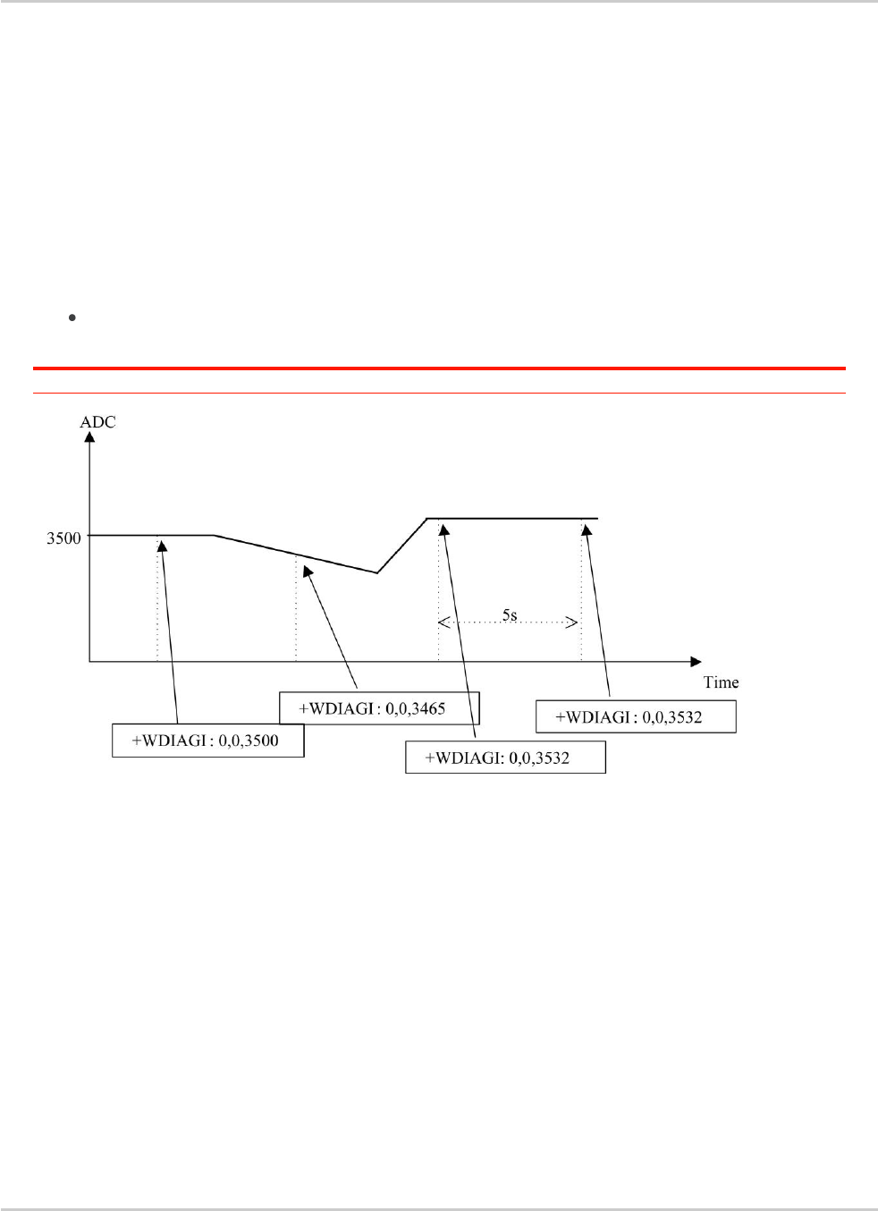
AT Commands Interface Guide for
Firmware 7.52
Error! Use the Home tab to apply Titre 1 to the text that you want to
appear here.
Error! Use the Home tab to apply Titre 2 to the text that you want to
appear here.
Rev. 1.0 Volume 4 March 7, 2014 146
23.3.6. Notes
Unsolicited responses for self diagnostic are only returned through one port. If these responses are
already activated on a port and if the activation is made on another port, the command will return
"+CME ERROR: 552" specific error.
Values over 4650 mV are not used
After a +WBCI=0 indication (minimum battery level reached), the selfdiagnostic is stopped.
Only one <type> can be activated at the same time.
Examples of selfdiagnostic feature behaviour
Example 1
AT+WDIAG=0,1,5,0,0,0,0
Note: ADC selfdiagnostic started with a 5s period.
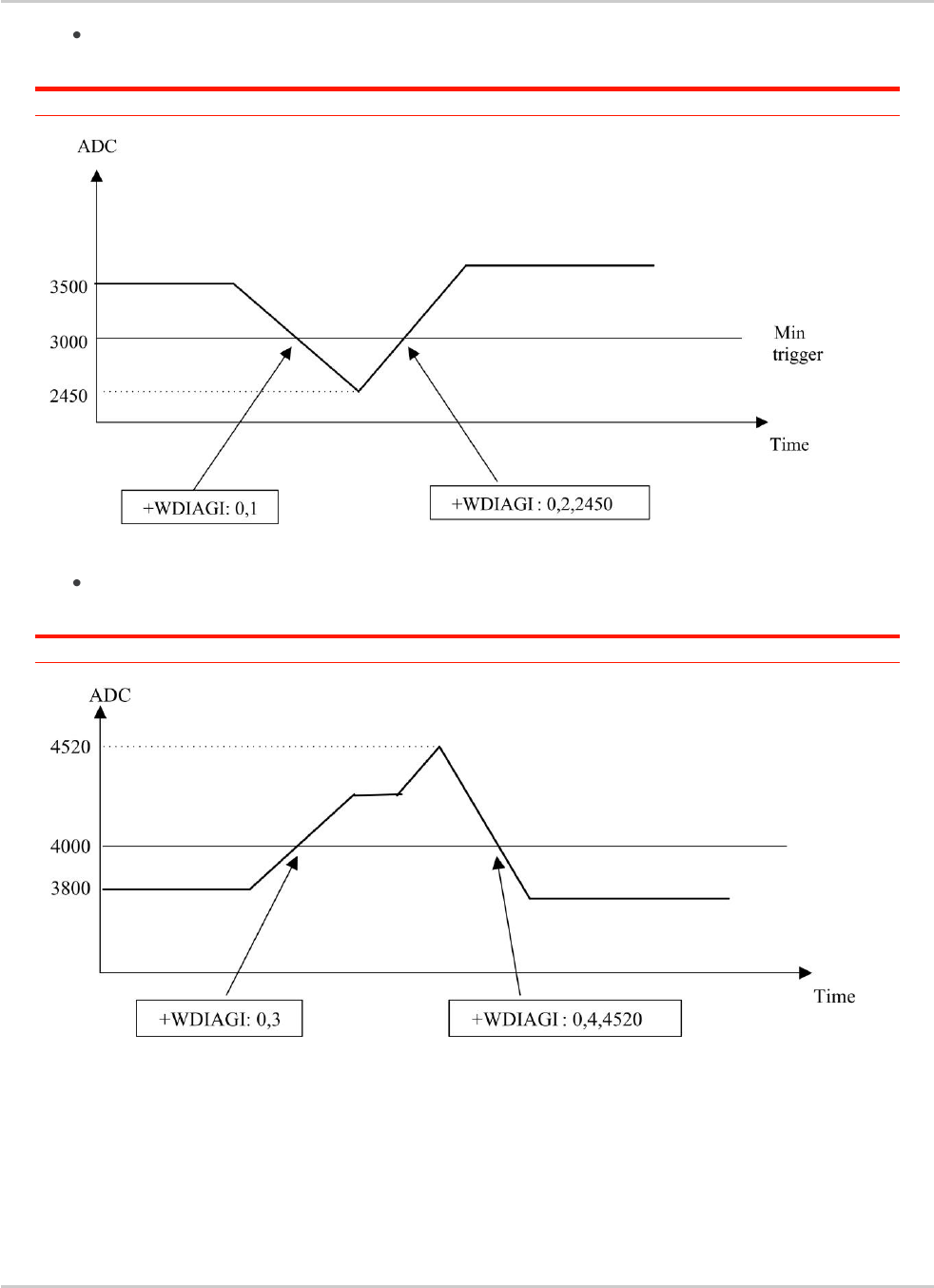
AT Commands Interface Guide for
Firmware 7.52
Error! Use the Home tab to apply Titre 1 to the text that you want to
appear here.
Error! Use the Home tab to apply Titre 2 to the text that you want to
appear here.
Rev. 1.0 Volume 4 March 7, 2014 147
Example 2
AT+WDIAG=0,1,0,3000,0,0,0
Note: ADC selfdiagnostic started in "best effort" with a 3000 mV minimum threshold.
Example 3
AT+WDIAG=0,1,0,0,4000,0,0
Note: ADC selfdiagnostic started in "best effort" with a 4000 mV maximum threshold
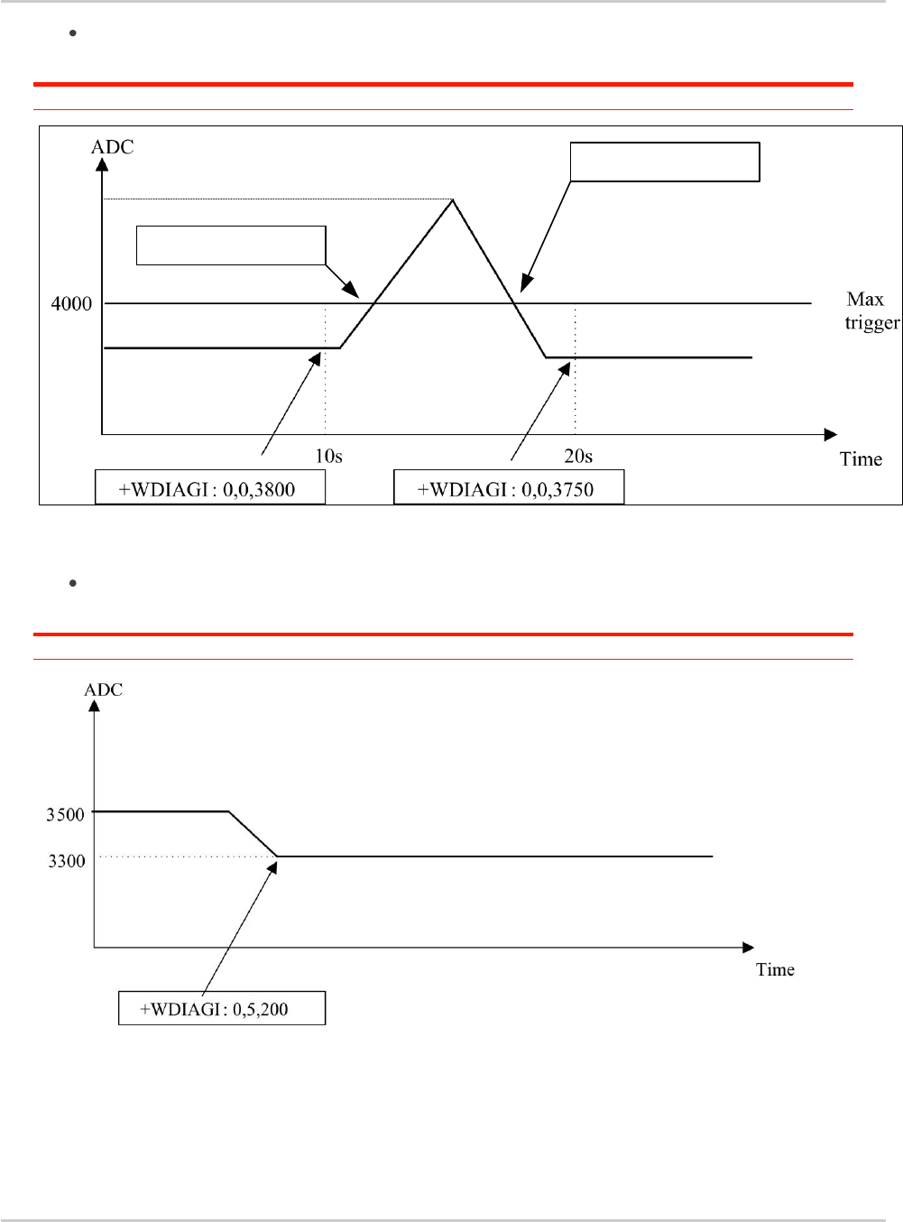
AT Commands Interface Guide for
Firmware 7.52
Error! Use the Home tab to apply Titre 1 to the text that you want to
appear here.
Error! Use the Home tab to apply Titre 2 to the text that you want to
appear here.
Rev. 1.0 Volume 4 March 7, 2014 148
Example 4
AT+WDIAG=0,1,10,0,4000,0,0
Note: ADC selfdiagnostic started with a 10s period for a 4000 mV maximum threshold.
+WDIAGI: 3
+WDIAGI: 4,4300
4300
Example 5
AT+WDIAG=0,1,0,0,0,100,1
Note: ADC self diagnostic started in "best effort" with a 100 mV delta threshold.

Rev. 1.0 Volume 4 March 7, 2014 149
24. CPHS Commands
24.1. CPHS Command: +CPHS
24.1.1. Description
This Sierra Wireless proprietary command is used to activate, deactivate or interrogate a CPHS
feature (e.g. voice mail indicator, mail box number…)
It also activates the following unsolicited responses:
+WMVI which indicates the status of the LINE 1, LINE 2, DATA or FAX mailboxes.
+WDCI which provides the call forwarding flags.
Note: This command is used to specifically manage the SIM stored Voicemail Numbers. Any actions related
to the ME Memory stored Voicemail Numbers MUST be managed through the +CSVM Command.
Note: In case of any SL808xT modules, only Voice mail indicator service is supported. As a consequence,
all +CPHS requests with <Fctld> different from value 1 will return +CME ERROR: 3
Note: If a UICC with an active USIM application is inserted and module is different from SL808xT , this
command always returns +CME ERROR: 3.
24.1.2. Syntax
For <Mode>=0 or 1:
Action command
AT+CPHS=<Mode>,<FctId>
OK
For <Mode>=2 and <FctId>=1:
Action command
AT+CPHS=<Mode>,<FctId>
+WVMI: <LineId>,<VoiceMailStatus>
[+WVMI: <LineId>,<VoiceMailStatus>[…]]
OK
For <Mode>=2 and <FctId>=2:
Action command
AT+CPHS=<Mode>,<FctId>
+WMBN: <Lineld>,[<number>],[<type>],[<name>],<NumberStatus>
[+WMBN: <Lineld>,[<number>],[<type>],[<name>],<NumberStatus>[…]]
OK

AT Commands Interface Guide for
Firmware 7.52
Error! Use the Home tab to apply Titre 1 to the text that you want to
appear here.
Error! Use the Home tab to apply Titre 2 to the text that you want to
appear here.
Rev. 1.0 Volume 4 March 7, 2014 150
For <Mode>=2 and <FctId>=3:
Action command
AT+CPHS=<Mode>,<FctId>
+WALS: <Lineld>
OK
For <Mode>=2 and <FctId>=4:
Action command
AT+CPHS=<Mode>,<FctId>
+WDCI: <LineId>,<DivertedStatus>
[+WDCI: <LineId>,<DivertedStatus>[…]]
OK
For <Mode>=2 and <FctId>=5:
Action command
AT+CPHS=<Mode>,<FctId>[,<type format>]
+WNON: <type format>,<operator name>
OK
For <Mode>=2 and <FctId>=6:
Action command
AT+CPHS=<Mode>,<FctId>[,<data field>]
+WCPI: <data field>,<InfoStatus>
OK
For <Mode>=2 and <FctId>=7:
Action command
AT+CPHS=<Mode>,<FctId>,<Service>
+WCSP: <Service>,<ServiceStatus>
OK
Read command
AT+CPHS?
+CPHS: <FctId>[,<Status>]
[+CPHS: <FctId>[,<Status>][…]]
OK

AT Commands Interface Guide for
Firmware 7.52
Error! Use the Home tab to apply Titre 1 to the text that you want to
appear here.
Error! Use the Home tab to apply Titre 2 to the text that you want to
appear here.
Rev. 1.0 Volume 4 March 7, 2014 151
Test command
AT+CPHS=?
OK
Unsolicited response
+WVMI: <LineId>,<VoiceMailStatus>
Unsolicited response
+WDCI: <LineId>,<DivertedStatus>
24.1.3. Parameters and Defined Values
<Mode>:
requested operation
this parameter has not effect for alternate line service, Network Operator Name,
CPHS information and Customer Profile Service features (<FctId>=3,5,6,7).
default value: 0 for <FctId>=1,2,4
0
deactivate a CPHS feature
1
activate a CPHS feature
2
interrogate a CPHS status
< FctId>:
CPHS feature CPHS feature
the Customer Service Profile and Alternate Line Service features are activated if
the field is set in CPHS information and CSP files. The Network Operator Name
is activated if at least one of the two format names exist (long or short
format).This is done at initialization.
1
voice mail indicator
2
mail box number
3
alternate line service
4
diverted call indicator
5
network operator name
6
CPHS Information
7
Customer Service Profile
<Status>:
CPHS feature state
0
disabled

AT Commands Interface Guide for
Firmware 7.52
Error! Use the Home tab to apply Titre 1 to the text that you want to
appear here.
Error! Use the Home tab to apply Titre 2 to the text that you want to
appear here.
Rev. 1.0 Volume 4 March 7, 2014 152
1
enabled
<Lineld>:
line identity
1
line 1
2
line 2
3
data
4
fax
<VoiceMailStatus>:
voice mail status
0
no message waiting
1
at least one message is waiting
<number>:
phone number in ASCII format
string type
<type>:
TON/NPI Type of address octet (refer GSM 04.08 subclause 10.5.4.7 [6])
integer type
129
ISDN / telephony numbering plan, national / international unknown
145
ISDN / telephony numbering plan, international number
161
ISDN / telephony numbering plan, national number
128-255
other values (refer GSM 04.08 section 10.5.4.7 [6])
<name>:
name of mailbox
string type
the +WPCS command affects the format of the mailbox <name> entry
the maximum length is SIM dependent
<NumberStatus>:
Indicates if <number> can be updated or not
0
update is not possible
1
update is possible
<DivertedStatus>:
divert Call Status
0
disabled
1
enabled
<type format>:
<operator name> format

AT Commands Interface Guide for
Firmware 7.52
Error! Use the Home tab to apply Titre 1 to the text that you want to
appear here.
Error! Use the Home tab to apply Titre 2 to the text that you want to
appear here.
Rev. 1.0 Volume 4 March 7, 2014 153
0
long format (default value)
1
short format
<operator name>:
operator name
string type
<data field>:
CPHS information field bit number
range: 0-25 (default value if omitted: 0)
If <data field> field is equal to 0, the whole CPHS information field will be displayed
in <InfoStatus> parameter
Please refer to section “CPHS information field” in the appendices
<InfoStatus>:
CPHS information field status
0
service is not customer-accessible
1
service is customer-accessible
"xxxxxxxx"
whole CPHS information bit field
hexadecimal string (8 digits)
<Service>:
CSP field bit number
range: 1-81
Please refer to section “CSP constants” in the appendices.
<ServiceStatus>:
CSP bit status
0
service is not customer-accessible
1
service is customer-accessible
24.1.4. Parameter Storage
The <Mode> parameter is stored in EEPROM without using the AT&W.command. The default value
can be restored using AT&F.

AT Commands Interface Guide for
Firmware 7.52
Error! Use the Home tab to apply Titre 1 to the text that you want to
appear here.
Error! Use the Home tab to apply Titre 2 to the text that you want to
appear here.
Rev. 1.0 Volume 4 March 7, 2014 154
24.1.5. Examples
Command
Responses
AT+CPHS?
Note: Interrogate the status of CPHS functionality
+CPHS: 1,0
Note: The voice mail indicator functionality is deactivated
+CPHS: 2,0
Note: The mail box number functionality is deactivated
+CPHS: 3,1
Note: The alternate line service functionality is activated
+CPHS: 4,0
Note: The divert call indicator functionality is deactivated
+CPHS: 5,1
Note: The network operator name functionality is activated
+CPHS: 6,1
Note: The CPHS information functionality is activated
+CPHS: 7,1
Note: The customer service profile functionality is activated
OK
AT+CPHS=1,1
Note: Activate the voice mail indicator functionality
OK
AT+CPHS?
Note: Interrogate the status of CPHS functionality
+CPHS: 1,1
Note: The voice mail indicator functionality is activated
+CPHS: 2,0
Note: The mail box number functionality is deactivated
+CPHS: 3,1
Note: The alternate line service functionality is activated
+CPHS: 4,0
Note: The divert call indicator functionality is deactivated
+CPHS: 5,1
Note: The network operator name functionality is activated
+CPHS: 6,1
Note: The CPHS information functionality is activated
+CPHS: 7,1
Note: The customer service profile functionality is activated
OK
+WVMI: 1,1
Note: A message is waiting on line 1

AT Commands Interface Guide for
Firmware 7.52
Error! Use the Home tab to apply Titre 1 to the text that you want to
appear here.
Error! Use the Home tab to apply Titre 2 to the text that you want to
appear here.
Rev. 1.0 Volume 4 March 7, 2014 155
Command
Responses
+WVMI: 2,1
Note: A message is waiting on line 2
AT+CPHS=1,4
Note: Activate the divert call indicator functionality
OK
**** The call forwarding is active on line 1 *****
+WDCI: 1,1
Note: Call forwarding is activated on line 1
AT+CPHS=2,1
Note: Interrogate the status of voice mail indicator
functionality
+WVMI: 1,1
Note: A message is waiting on line 1
+WVMI: 2,1
Note: A message is waiting on line 2
+WVMI: 3,0
Note: No data waiting
+WVMI: 4,0
Note: No fax waiting
OK
AT+CPHS=1,2
Note: Activate the mail box number functionality
OK
AT+WALS=1
+WALS: 2
OK
Note: Interrogate the status of activated line
Note: The current line is number 2
AT+CPHS=0,4
Note: Deactivate the divert call indicator functionality
OK

AT Commands Interface Guide for
Firmware 7.52
Error! Use the Home tab to apply Titre 1 to the text that you want to
appear here.
Error! Use the Home tab to apply Titre 2 to the text that you want to
appear here.
Rev. 1.0 Volume 4 March 7, 2014 156
Command
Responses
AT+CPHS?
Note: Interrogate the status of CPHS functionality
+CPHS: 1,1
Note: The voice mail indicator functionality is activated
+CPHS: 2,1
Note: The mail box number functionality is activated
+CPHS: 3,1
Note: The alternate line service functionality is activated
+CPHS: 4,0
Note: The divert call indicator functionality is deactivated
+CPHS: 5,1
Note: The network operator name functionality is activated
+CPHS: 6,1
Note: The CPHS Information functionality is activated
+CPHS: 7,1
Note: The Customer Service Profile functionality is activated
OK
AT+CPHS=2,2
Note: Get current values
+WMBN: 1,"19254871234",129,,1
Note: Mail box number for line 1
+WMBN: 2,,,1
Note: Mail box number for line 2
+WMBN: 3,,,1
Note: Mail box number for data line
+WMBN: 4,,,1
Note: Mail box number for fax line
OK
Note: Only line1 can be updated
AT+CPHS=2,5
Note: Get the operator name
+WNON: 0,"Orange F"
OK
AT+CPHS=2,7,9
Note: Get the current status for barring of all
outgoing calls
+WCSP: 9,1
OK
Note: Barring of all outgoing calls is customer accessible.
AT+CPHS=2,6
Note: Get the current status for all CPHS info field
+WCPI: 0,"0033000F"
OK
AT+CPHS=2,6,13
Note: Get the current status for call forward activated
indicator for line 1
+WCPI: 13,1
OK

AT Commands Interface Guide for
Firmware 7.52
Error! Use the Home tab to apply Titre 1 to the text that you want to
appear here.
Error! Use the Home tab to apply Titre 2 to the text that you want to
appear here.
Rev. 1.0 Volume 4 March 7, 2014 157
24.1.6. Notes
This command may answer "+CME ERROR: 3" if:
the CPHS feature is disabled
the SIM card does not support this CPHS
a UICC with an active USIM application is inserted on any module different from SL808xT
SL808xT module is used and <Fctld> is set to any value different from 1 (only voice mail
indicator is supported on SL808xT)

AT Commands Interface Guide for
Firmware 7.52
Error! Use the Home tab to apply Titre 1 to the text that you want to
appear here.
Error! Use the Home tab to apply Titre 2 to the text that you want to
appear here.
Rev. 1.0 Volume 4 March 7, 2014 158
24.2. Sierra Wireless CPHS Mail Box Number
+WMBN
24.2.1. Description
This Sierra Wireless proprietary command sets the different mailbox numbers in SIM. The +CPHS
command can be used to know which mailbox numbers can be updated.
Note: If a UICC with an active USIM application is inserted, this command always returns +CME ERROR: 3.
24.2.2. Syntax
Action command
AT+WMBN=<Lineld>[,<number>,[<type>],[<name>]]
OK
Read command
AT+WMBN?
OK
Test command
AT+WMBN=?
OK
24.2.3. Parameters and Defined Values
<Lineld>:
line associated to the mailbox
1
line 1
2
line 2
3
data
4
fax

AT Commands Interface Guide for
Firmware 7.52
Error! Use the Home tab to apply Titre 1 to the text that you want to
appear here.
Error! Use the Home tab to apply Titre 2 to the text that you want to
appear here.
Rev. 1.0 Volume 4 March 7, 2014 159
<number>:
phone number
ASCII format
up to 20 digits
<type>:
TON/NPI Type of address octet for <number> (refer GSM 04.08 subclause 10.5.4.7
[6]); default 145 when dialing string inclues international access code character “+”,
otherwise 129
integer type
129
ISDN / telephony numbering plan, national / international unknown
145
ISDN / telephony numbering plan, international number
161
ISDN / telephony numbering plan, national number
128-255
other values (refer GSM 04.08 section 10.5.4.7 [6])
<name>:
name of mailbox
string type
the +WPCS command affects the format of the mailbox <name> entry.
the maximum length is SIM dependent.
24.2.4. Parameter Storage
None.

AT Commands Interface Guide for
Firmware 7.52
Error! Use the Home tab to apply Titre 1 to the text that you want to
appear here.
Error! Use the Home tab to apply Titre 2 to the text that you want to
appear here.
Rev. 1.0 Volume 4 March 7, 2014 160
24.2.5. Examples
Command
Responses
AT+CPHS=2,2
Note: Gets the current mail box numbers in SIM
+WMBN:1,"0123456789",129,"Home",1
+WMBN:2,"9876543210",129,"Work",1
+WMBN:3,,,,1
+WMBN:4,,,,1
OK
AT+WMBN=1,"+0033122334455",145
OK
Note: Sets mailbox number for line 1
Note: Mailbox number for line 1 is set
AT+WMBN=2
OK
Note: Erases mailbox number & name for line 2
AT+CPHS=2,2
+WMBN: 1,"+33122334455",145,,1
+WMBN: 2,,,,,1
+WMBN: 3,,,,,1
+WMBN: 4,,,,,1
OK
Note: Gets the current mail box numbers again

AT Commands Interface Guide for
Firmware 7.52
Error! Use the Home tab to apply Titre 1 to the text that you want to
appear here.
Error! Use the Home tab to apply Titre 2 to the text that you want to
appear here.
Rev. 1.0 Volume 4 March 7, 2014 161
24.3. Sierra Wireless Alternate Line Service +WALS
24.3.1. Description
This Sierra Wireless proprietary command allows to set and to get an active line. The +CPHS
command can be used to know which line is activated.
Note: If a UICC with an active USIM application is inserted, this command always returns +CME ERROR: 3.
24.3.2. Syntax
Action command
AT+WALS=<CmdType>[,<Lineld>]
[+WALS: <Lineld>]
OK
Read command
AT+WALS?
+WALS: <Lineld>
OK
Test command
AT+WALS=?
+WALS: (list of supported <CmdType>s),(list of supported <Lineld>s)
OK

AT Commands Interface Guide for
Firmware 7.52
Error! Use the Home tab to apply Titre 1 to the text that you want to
appear here.
Error! Use the Home tab to apply Titre 2 to the text that you want to
appear here.
Rev. 1.0 Volume 4 March 7, 2014 162
24.3.3. Parameters and Defined Values
<CmdType>:
requested operation
0
sets active line
1
gets active line
<Lineld>:
line number
used only with <CmdType>=0
1
line 1
2
line 2
24.3.4. Parameter Storage
The <LineId> parameter is stored in EEPROM without using the AT&W command.
24.3.5. Examples
Command
Responses
AT+WALS=?
+WALS: (0-1),(1-2)
OK
AT+WALS=0,1
Note: Activate line 1
+WALS:1
OK
AT+WALS=1
Note: Get the current activated line
+WALS:1
OK
AT+CPHS=2,3
Note: Get the current activated line
+WALS:1
OK

Rev. 1.0 Volume 4 March 7, 2014 163
25. Fax Commands
25.1. Introduction
The fax service provided by the product is class 1 compliant. However, only the core commands
defined by ITU T.31 are supported. This means that commands such as AT+FAR, +FCC, etc. are not
supported.
Autobauding must be enabled to set up the product for fax.
All the following commands return an ERROR response code if they are not issued during
communication.

AT Commands Interface Guide for
Firmware 7.52
Error! Use the Home tab to apply Titre 1 to the text that you want to
appear here.
Error! Use the Home tab to apply Titre 2 to the text that you want to
appear here.
Rev. 1.0 Volume 4 March 7, 2014 164
25.2. Transmit Speed +FTM
25.2.1. Description
This command sets the fax transmit speed.
25.2.2. Syntax
Action command
AT+FTM=<speed>
OK
Read command
None
Test command
AT+FTM=?
(list of supported <speed>s)
OK

AT Commands Interface Guide for
Firmware 7.52
Error! Use the Home tab to apply Titre 1 to the text that you want to
appear here.
Error! Use the Home tab to apply Titre 2 to the text that you want to
appear here.
Rev. 1.0 Volume 4 March 7, 2014 165
25.2.3. Parameters and Defined Values
<speed>:
fax transmit speed
24
2400 bps (modem type V.27ter)
48
4800 bps (modem type V.27ter)
72
7200 bps (modem type V.29)
73
7200 bps (long) (modem type V.17)
74
7200 bps (short) (modem type V.17)
96
9600 bps (modem type V.29)
97
9600 bps (long) (modem type V.17)
98
9600 bps (short) (modem type V.17)
121
12000 bps (long) (modem type V.17)
122
12000 bps (short) (modem type V.17)
145
14400 bps (long) (modem type V.17)
146
14400 bps (short) (modem type V.17)
25.2.4. Parameter Storage
None.
25.2.5. Examples
Command
Responses
AT+FTM=145
Note: Set fax speed at 14400 bps for a V.17
type modem
OK
AT+FTM=?
Note: Get possible values
(24,48,72,73,74,96,97,98,121,122,145,146)
OK

AT Commands Interface Guide for
Firmware 7.52
Error! Use the Home tab to apply Titre 1 to the text that you want to
appear here.
Error! Use the Home tab to apply Titre 2 to the text that you want to
appear here.
Rev. 1.0 Volume 4 March 7, 2014 166
25.3. Receive Speed +FRM
25.3.1. Description
This command sets the fax receive speed.
25.3.2. Syntax
Action command
AT+FRM=<speed>
OK
Read command
None
Test command
AT+FRM=?
(list of supported <speed>s)
OK

AT Commands Interface Guide for
Firmware 7.52
Error! Use the Home tab to apply Titre 1 to the text that you want to
appear here.
Error! Use the Home tab to apply Titre 2 to the text that you want to
appear here.
Rev. 1.0 Volume 4 March 7, 2014 167
25.3.3. Parameters and Defined Values
<speed>:
fax receive speed
24
2400 bps (modem type V.27ter)
48
4800 bps (modem type V.27ter)
72
7200 bps (modem type V.29)
73
7200 bps (long) (modem type V.17)
74
7200 bps (short) (modem type V.17)
96
9600 bps (modem type V.29)
97
9600 bps (long) (modem type V.17)
98
9600 bps (short) (modem type V.17)
121
12000 bps (long) (modem type V.17)
122
12000 bps (short) (modem type V.17)
145
14400 bps (long) (modem type V.17)
146
14400 bps (short) (modem type V.17)
25.3.4. Parameter Storage
None.
25.3.5. Examples
Command
Responses
AT+FRM=?
Note: Get possible values
(24,48,72,73,74,96,97,98,121,122,145,146)
OK
AT+FRM=145
Note: Set fax speed at 14400 bps for a V.17
type modem
OK

AT Commands Interface Guide for
Firmware 7.52
Error! Use the Home tab to apply Titre 1 to the text that you want to
appear here.
Error! Use the Home tab to apply Titre 2 to the text that you want to
appear here.
Rev. 1.0 Volume 4 March 7, 2014 168
25.4. HDLC Transmit Speed +FTH
25.4.1. Description
This command sets the fax transmit speed using the HDLC protocol.
25.4.2. Syntax
Action command
AT+FTH=<speed>
OK
Read command
None
Test command
AT+FTH=?
(list of supported <speed>s)
OK
25.4.3. Parameters and Defined Values
<speed>:
HDLC fax transmit speed
3
V.21 channels 300 bps
25.4.4. Parameter Storage
None.

AT Commands Interface Guide for
Firmware 7.52
Error! Use the Home tab to apply Titre 1 to the text that you want to
appear here.
Error! Use the Home tab to apply Titre 2 to the text that you want to
appear here.
Rev. 1.0 Volume 4 March 7, 2014 169
25.4.5. Examples
Command
Responses
AT+FTH=3
Note: Set fax speed at 300 bps
OK
AT+FTH=?
Note: Get possible values
(3)
OK

AT Commands Interface Guide for
Firmware 7.52
Error! Use the Home tab to apply Titre 1 to the text that you want to
appear here.
Error! Use the Home tab to apply Titre 2 to the text that you want to
appear here.
Rev. 1.0 Volume 4 March 7, 2014 170
25.5. HDLC Receive Speed +FRH
25.5.1. Description
This command sets the fax receive speed using the HDLC protocol.
25.5.2. Syntax
Action command
AT+FRH=<speed>
OK
Read command
None
Test command
AT+FRH=?
(list of supported <speed>s)
OK
25.5.3. Parameters and Defined Values
<speed>:
HDLC fax receive speed
3
V.21 channels 300 bps
25.5.4. Parameter Storage
None.

AT Commands Interface Guide for
Firmware 7.52
Error! Use the Home tab to apply Titre 1 to the text that you want to
appear here.
Error! Use the Home tab to apply Titre 2 to the text that you want to
appear here.
Rev. 1.0 Volume 4 March 7, 2014 171
25.5.5. Examples
Command
Responses
AT+FRH=3
Note: Set fax speed at 300 bps
OK
AT+FRH=?
Note: Get possible values
(3)
OK

AT Commands Interface Guide for
Firmware 7.52
Error! Use the Home tab to apply Titre 1 to the text that you want to
appear here.
Error! Use the Home tab to apply Titre 2 to the text that you want to
appear here.
Rev. 1.0 Volume 4 March 7, 2014 172
25.6. Stop Transmission and Wait +FTS
25.6.1. Description
This command stops the transmission for a specified period.
25.6.2. Syntax
Action command
AT+FTS=<n>
OK
Read command
None
Test command
AT+FTS=?
(list of supported <n>s)
OK
25.6.3. Parameters and Defined Values
<n>:
fax transmit silence period
0-255
silence period (unit is 10 ms)
25.6.4. Parameter Storage
None.

AT Commands Interface Guide for
Firmware 7.52
Error! Use the Home tab to apply Titre 1 to the text that you want to
appear here.
Error! Use the Home tab to apply Titre 2 to the text that you want to
appear here.
Rev. 1.0 Volume 4 March 7, 2014 173
25.6.5. Examples
Command
Responses
AT+FTS=?
Note: Test command
(0-255)
OK
AT+FTS=50
OK
Note: Stops transmission and waits for 0.5s

AT Commands Interface Guide for
Firmware 7.52
Error! Use the Home tab to apply Titre 1 to the text that you want to
appear here.
Error! Use the Home tab to apply Titre 2 to the text that you want to
appear here.
Rev. 1.0 Volume 4 March 7, 2014 174
25.7. Receive Silence +FRS
25.7.1. Description
This command causes the embedded module to stop listening to the network and report back to the
DTE after the specified period.
It is aborted if any character is received from the application.
25.7.2. Syntax
Action command
AT+FRS=<n>
OK
Read command
None
Test command
AT+FRS=?
(list of supported <n>s)
OK
25.7.3. Parameters and Defined Values
<n>:
fax receive non listening period
0-255
non listening period (unit is 10ms)
25.7.4. Parameter Storage
None.

AT Commands Interface Guide for
Firmware 7.52
Error! Use the Home tab to apply Titre 1 to the text that you want to
appear here.
Error! Use the Home tab to apply Titre 2 to the text that you want to
appear here.
Rev. 1.0 Volume 4 March 7, 2014 175
25.7.5. Examples
Command
Responses
AT+FRS=?
Note: Get possible values
(0-255)
OK
AT+FRS=50
OK
Note: Stops listening and waits for 0.5s
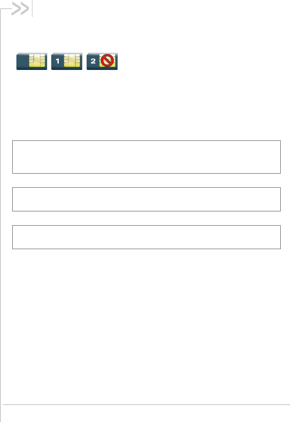
Rev. 1.0 Volume 4 March 7, 2014 176
26. Fax class 2 Commands
26.1. Transmit Data +FDT
26.1.1. Description
This command prefixes data transmission.
26.1.2. Syntax
Action command
AT+FDT
OK
Read command
None
Test command
None
26.1.3. Parameters and Defined Values
None.
26.1.4. Parameter Storage
None.
26.1.5. Examples
None.

AT Commands Interface Guide for
Firmware 7.52
Error! Use the Home tab to apply Titre 1 to the text that you want to
appear here.
Error! Use the Home tab to apply Titre 2 to the text that you want to
appear here.
Rev. 1.0 Volume 4 March 7, 2014 177
26.2. Receive Data +FDR
26.2.1. Description
This command initiates data reception.
26.2.2. Syntax
Action command
AT+FDR
OK
Read command
None
Test command
None
26.2.3. Parameters and Defined Values
None.
26.2.4. Parameter Storage
None.
26.2.5. Examples
None.

AT Commands Interface Guide for
Firmware 7.52
Error! Use the Home tab to apply Titre 1 to the text that you want to
appear here.
Error! Use the Home tab to apply Titre 2 to the text that you want to
appear here.
Rev. 1.0 Volume 4 March 7, 2014 178
26.3. Transmit Page Punctuation +FET
26.3.1. Description
This command punctuates page and document transmission after the +FDT command. It indicates
that the current page is complete, and if there are additional pages to send.
The +FET unsolicited response reports post page message response.
26.3.2. Syntax
Action command
AT+FET=<ppm>
OK
Read command
None
Test command
None
Unsolicited response
+FET: <ppm>

AT Commands Interface Guide for
Firmware 7.52
Error! Use the Home tab to apply Titre 1 to the text that you want to
appear here.
Error! Use the Home tab to apply Titre 2 to the text that you want to
appear here.
Rev. 1.0 Volume 4 March 7, 2014 179
26.3.3. Parameters and Defined Values
<ppm>:
post page message
0
another page next, same document
1
another document next
2
no more pages or documents
3
another partial page next
4
another page, procedure interrupt
5
another document, procedure interrupt
6
all done, procedure interrupt
26.3.4. Parameter Storage
None.
26.3.5. Examples
Command
Responses
AT+FET=0
OK
Note: Send another page of the same document

AT Commands Interface Guide for
Firmware 7.52
Error! Use the Home tab to apply Titre 1 to the text that you want to
appear here.
Error! Use the Home tab to apply Titre 2 to the text that you want to
appear here.
Rev. 1.0 Volume 4 March 7, 2014 180
26.4. Page Transfer Status Parameters +FPTS
26.4.1. Description
This command sets post page transfer response.
The +FPTS unsolicited response reports received page transfer status.
26.4.2. Syntax
Action command
AT+FPTS=<ppr>
OK
Read command
None
Test command
None
Unsolicited response
+FPTS: <ppr>
26.4.3. Parameters and Defined Values
<ppr>:
post page transfer response
1
page good
2
page bad; retry requested
3
page good; retrain requested
4
page bad; interrupt requested

AT Commands Interface Guide for
Firmware 7.52
Error! Use the Home tab to apply Titre 1 to the text that you want to
appear here.
Error! Use the Home tab to apply Titre 2 to the text that you want to
appear here.
Rev. 1.0 Volume 4 March 7, 2014 181
5
page good; interrupt requested
26.4.4. Parameter Storage
None.
26.4.5. Examples
None.

AT Commands Interface Guide for
Firmware 7.52
Error! Use the Home tab to apply Titre 1 to the text that you want to
appear here.
Error! Use the Home tab to apply Titre 2 to the text that you want to
appear here.
Rev. 1.0 Volume 4 March 7, 2014 182
26.5. Terminate Session +FK
26.5.1. Description
This command causes the product to terminate the session.
26.5.2. Syntax
Action command
AT+FK
OK
Read command
None
Test command
None
26.5.3. Parameters and Defined Values
None.
26.5.4. Parameter Storage
None.
26.5.5. Examples
None.

AT Commands Interface Guide for
Firmware 7.52
Error! Use the Home tab to apply Titre 1 to the text that you want to
appear here.
Error! Use the Home tab to apply Titre 2 to the text that you want to
appear here.
Rev. 1.0 Volume 4 March 7, 2014 183
26.6. Page Transfer Bit Order +FBOR
26.6.1. Description
This command sets the bit order for negotiation and fax page transfer. The order is related to the bit
order on radio link. .
26.6.2. Syntax
Action command
AT+FBOR=<n>
OK
Read command
AT+FBOR?
<n>
OK
Test command
AT+FBOR=?
(list of supported <n>s)
OK
26.6.3. Parameters and Defined Values
<n>:
Bit order for negotiation
Bit order for page transfer
0
same (default)
same (default)
1
same
reverse
2
reverse
same

AT Commands Interface Guide for
Firmware 7.52
Error! Use the Home tab to apply Titre 1 to the text that you want to
appear here.
Error! Use the Home tab to apply Titre 2 to the text that you want to
appear here.
Rev. 1.0 Volume 4 March 7, 2014 184
3
reverse
reverse
26.6.4. Parameter Storage
The <n> parameter is stored in EEPROM using the AT&W command. The default value can be
restored using AT&F.
26.6.5. Examples
Command
Responses
AT+FBOR=?
(0-3)
OK
AT+FBOR=0
OK
Note: Set bit order to 0
Note: Bit order set at default settings
AT+FBOR?
0
OK

AT Commands Interface Guide for
Firmware 7.52
Error! Use the Home tab to apply Titre 1 to the text that you want to
appear here.
Error! Use the Home tab to apply Titre 2 to the text that you want to
appear here.
Rev. 1.0 Volume 4 March 7, 2014 185
26.7. Buffer Size Report +FBUF
26.7.1. Description
This command requests the size of the exchange buffer between the embedded module and the fax
application.
26.7.2. Syntax
Action command
None
Read command
AT+FBUF?
<buffer size>
OK
Test command
None
26.7.3. Parameters and Defined Values
<buffer size>:
size of the exchange buffer in bytes
integer type
26.7.4. Parameter Storage
None.

AT Commands Interface Guide for
Firmware 7.52
Error! Use the Home tab to apply Titre 1 to the text that you want to
appear here.
Error! Use the Home tab to apply Titre 2 to the text that you want to
appear here.
Rev. 1.0 Volume 4 March 7, 2014 186
26.7.5. Examples
Command
Responses
AT+FBUF?
1024
OK
Note: Get current buffer size
Note: Current buffer size is 1024 bytes

AT Commands Interface Guide for
Firmware 7.52
Error! Use the Home tab to apply Titre 1 to the text that you want to
appear here.
Error! Use the Home tab to apply Titre 2 to the text that you want to
appear here.
Rev. 1.0 Volume 4 March 7, 2014 187
26.8. Copy Quality Checking +FCQ
26.8.1. Description
This command controls copy quality checking for receiving faxes.
26.8.2. Syntax
Action command
AT+FCQ=<n>
OK
Read command
AT+FCQ?
<n>
OK
Test command
AT+FCQ=?
(list of supported <n>s)
OK
26.8.3. Parameters and Defined Values
<n>:
copy quality mode
0
copy quality checking (default value)
26.8.4. Parameter Storage
The <n> parameter is stored in EEPROM using the AT&W command. The default value can be
restored using AT&F.

AT Commands Interface Guide for
Firmware 7.52
Error! Use the Home tab to apply Titre 1 to the text that you want to
appear here.
Error! Use the Home tab to apply Titre 2 to the text that you want to
appear here.
Rev. 1.0 Volume 4 March 7, 2014 188
26.8.5. Examples
Command
Responses
AT+FCQ=?
(0)
OK

AT Commands Interface Guide for
Firmware 7.52
Error! Use the Home tab to apply Titre 1 to the text that you want to
appear here.
Error! Use the Home tab to apply Titre 2 to the text that you want to
appear here.
Rev. 1.0 Volume 4 March 7, 2014 189
26.9. Capability to Receive +FCR
26.9.1. Description
This command controls the capability of the embedded module to accept incoming faxes.
26.9.2. Syntax
Action command
AT+FCR=<n>
OK
Read command
AT+FCR?
<n>
OK
Test command
AT+FCR=?
(list of supported <n>s)
OK
26.9.3. Parameters and Defined Values
<n>:
capability to receive mode
0
The embedded module will not accept incoming faxes.
1
The embedded module will accept incoming faxes (default value)
26.9.4. Parameter Storage
The <n> parameter is stored in EEPROM using AT&W command. The default value can be restored
using AT&F.

AT Commands Interface Guide for
Firmware 7.52
Error! Use the Home tab to apply Titre 1 to the text that you want to
appear here.
Error! Use the Home tab to apply Titre 2 to the text that you want to
appear here.
Rev. 1.0 Volume 4 March 7, 2014 190
26.9.5. Examples
Command
Responses
AT+FCR=?
(0,1)
OK
AT+FCR=1
OK
AT+FCR?
1
OK

AT Commands Interface Guide for
Firmware 7.52
Error! Use the Home tab to apply Titre 1 to the text that you want to
appear here.
Error! Use the Home tab to apply Titre 2 to the text that you want to
appear here.
Rev. 1.0 Volume 4 March 7, 2014 191
26.10. Current Session Parameters +FDIS
26.10.1. Description
This command allows the DTE to configure the capabilities used for the current session.
The +FDIS unsolicited response reports remote capabilities.
The +FDCS unsolicited response reports current session capabilities.
26.10.2. Syntax
Action command
AT+FDIS=[<vr>][,[<br>][,[<wd>][,[<ln>][,[<df>][,[<ec>][,[<bf>][,[<st>]]]]]]]]
OK
Read command
AT+FDIS?
<vr>,<br>,<wd>,<ln>,<df>,<ec>,<bf>,<st>
OK
Test command
AT+FDIS=?
(list of supported <vr>s),(list of supported <br>s),(list of supported <wd>s),(list
of supported <ln>s),(list of supported <df>s),(list of supported <ec>s),(list of
supported <bf>s),(list of supported <st>s)
OK
Unsolicited response
+FDCS: <remote_vr>,<br>,<wd>,<ln>,<df>,<ec>,<bf>,<st>
+FDIS: <remote_vr>,<br>,<wd>,<ln>,<df>,<ec>,<bf>,<st>

AT Commands Interface Guide for
Firmware 7.52
Error! Use the Home tab to apply Titre 1 to the text that you want to
appear here.
Error! Use the Home tab to apply Titre 2 to the text that you want to
appear here.
Rev. 1.0 Volume 4 March 7, 2014 192
26.10.3. Parameters and Defined Values
<vr>:
vertical resolution
0
normal: 98 LPI (default value)
1
fine: 196 LPI
<remote_vr>:
remote vertical resolution (bitfield)
0x01
R8 ´ 7.7 l/mm, Fine (196 LPI)
0x02
R8 ´ 15.4 l/mm
0x04
R16 ´ 15.4 l/mm
0x08
200 dpi ´ 100 l/25.4 mm
0x10
200 dpi ´ 200 l/25.4 mm
0x20
200 dpi ´ 400 l/25.4 mm
0x40
300 dpi ´ 300 l/25.4 mm
<br>:
bit rate
0
2400 bps (modem type V.27 ter)
1
4800 bps (modem type V.27 ter)
2
7200 bps (modem type V.29)
3
9600 bps (modem type V.29, V.17). (default value if "DATA144" feature
IS NOT supported)
4
12000 bps (modem type V.33, V.17)
only when product supports "DATA144" feature
5
14400 bps (modem type V.33, V.17). (default value if "DATA144" feature
IS supported)
only when product supports "DATA144" feature
<wd>:
page width
0
1728 pixels in 215 mm (default value)
1
2048 pixels in 255 mm
2
2432 pixels in 303 mm

AT Commands Interface Guide for
Firmware 7.52
Error! Use the Home tab to apply Titre 1 to the text that you want to
appear here.
Error! Use the Home tab to apply Titre 2 to the text that you want to
appear here.
Rev. 1.0 Volume 4 March 7, 2014 193
<ln>:
page length
0
A4, 297 mm
1
B4, 364 mm
2
unlimited (default value)
<df>:
data compression format
0
1-D modified Huffman (default value)
1
2-D modified read
2
2-D uncompressed mode
3
2-D modified modified read
<ec>:
error correction
0
disable Fax ECM
<bf>:
binary file transfer
0
disable
<st>:
scan time per line
if <vr>=0
if <vr>=1
0
0 ms (default)
0 ms (default)
1
5 ms
5 ms
2
10 ms
5 ms
3
10 ms
10 ms
4
20 ms
10 ms
5
20 ms
20 ms
6
40 ms
20 ms
7
40 ms
40 ms

AT Commands Interface Guide for
Firmware 7.52
Error! Use the Home tab to apply Titre 1 to the text that you want to
appear here.
Error! Use the Home tab to apply Titre 2 to the text that you want to
appear here.
Rev. 1.0 Volume 4 March 7, 2014 194
26.10.4. Parameter Storage
The parameters are stored in EEPROM using the AT&W command. The default value can be restored
using AT&F.
26.10.5. Examples
Command
Responses
AT+FDIS=?
(0,1),(0-5),(0-2),(0-2),(0-3),
(0),(0),(0-7)
OK
AT+FDIS=,4
Note: Change bit rate
OK
AT+FDIS?
0,4,0,2,0,0,0,0
OK

AT Commands Interface Guide for
Firmware 7.52
Error! Use the Home tab to apply Titre 1 to the text that you want to
appear here.
Error! Use the Home tab to apply Titre 2 to the text that you want to
appear here.
Rev. 1.0 Volume 4 March 7, 2014 195
26.11. DCE Capabilities Parameters +FDCC
26.11.1. Description
This command allows the DTE to configure the capabilities used for the any session.
26.11.2. Syntax
Action command
AT+FDCC=[<vr>][,[<br>][,[<wd>][,[<ln>][,[<df>][,[<ec>][,[<bf>][,[<st>]]]]]]]]
OK
Read command
AT+FDCC?
<vr>,<br>,<wd>,<ln>,<df>,<ec>,<bf>,<st>
OK
Test command
AT+FDCC=?
(list of supported <vr>s),(list of supported <br>s),(list of supported <wd>s),(list
of supported <ln>s),(list of supported <df>s),(list of supported <ec>s),(list of
supported <bf>s),(list of supported <st>s)
OK
26.11.3. Parameters and Defined Values
<vr>:
vertical resolution
0
normal: 98 LPI (default value)
1
fine: 196 LPI

AT Commands Interface Guide for
Firmware 7.52
Error! Use the Home tab to apply Titre 1 to the text that you want to
appear here.
Error! Use the Home tab to apply Titre 2 to the text that you want to
appear here.
Rev. 1.0 Volume 4 March 7, 2014 196
<br>:
bit rate
0
2400 bps (modem type V.27 ter)
1
4800 bps (modem type V.27 ter)
2
7200 bps (modem type V.29)
3
9600 bps (modem type V.29, V.17). (default value if "DATA144" feature
IS NOT supported)
4
12000 bps (modem type V.33, V.17)
only when product supports "DATA144" feature
5
14400 bps (modem type V.33, V.17). (default value if "DATA144" feature
IS supported)
only when product supports "DATA144" feature
<wd>:
page width
0
1728 pixels in 215 mm (default value)
1
2048 pixels in 255 mm
2
2432 pixels in 303 mm
<ln>:
page length
0
A4, 297 mm
1
B4, 364 mm
2
unlimited (default value)
<df>:
data compression format
0
1-D modified Huffman (default value)
1
2-D modified read
2
2-D uncompressed mode
3
2-D modified modified read
<ec>:
error correction
0
disable Fax ECM
<bf>:
binary file transfer
0
disable

AT Commands Interface Guide for
Firmware 7.52
Error! Use the Home tab to apply Titre 1 to the text that you want to
appear here.
Error! Use the Home tab to apply Titre 2 to the text that you want to
appear here.
Rev. 1.0 Volume 4 March 7, 2014 197
<st>:
scan time per line
if <vr>=0
if <vr>=1
0
0 ms (default)
0 ms (default)
1
5 ms
5 ms
2
10 ms
5 ms
3
10 ms
10 ms
4
20 ms
10 ms
5
20 ms
20 ms
6
40 ms
20 ms
7
40 ms
40 ms
26.11.4. Parameter Storage
The parameters are stored in EEPROM using the AT&W command. The default value can be restored
using AT&F.
26.11.5. Examples
Command
Responses
AT+FDCC=?
(0,1),(0-5),(0-2),(0-2),(0-3),
(0),(0),(0-7)
OK
AT+FDCC=,4
OK
Note: Change bit rate
AT+FDCC?
0,4,0,2,0,0,0,0
OK

AT Commands Interface Guide for
Firmware 7.52
Error! Use the Home tab to apply Titre 1 to the text that you want to
appear here.
Error! Use the Home tab to apply Titre 2 to the text that you want to
appear here.
Rev. 1.0 Volume 4 March 7, 2014 198
26.12. Local ID String +FLID
26.12.1. Description
This command defines or queries the local ID string.
26.12.2. Syntax
Action command
AT+FLID=<string>
OK
Read command
AT+FLID?
<string>
OK
Test command
AT+FLID=?
(<nb_characters>),(list of supported <ascii_code>s)
OK
26.12.3. Parameters and Defined Values
<string>:
local ID string
string type
default value: empty string
<nb_characters>:
maximum number of characters
integer type
default value: 20

AT Commands Interface Guide for
Firmware 7.52
Error! Use the Home tab to apply Titre 1 to the text that you want to
appear here.
Error! Use the Home tab to apply Titre 2 to the text that you want to
appear here.
Rev. 1.0 Volume 4 March 7, 2014 199
<ascii_code>:
allowed ASCII code
range: 32-127
26.12.4. Parameter Storage
The <string> parameter is stored in EEPROM using the AT&W command. The default value can be
restored using AT&F.
26.12.5. Examples
Command
Responses
AT+FLID=?
(20),(32-127)
OK
AT+FLID="local ID string"
OK
AT+FLID?
local ID string
OK

AT Commands Interface Guide for
Firmware 7.52
Error! Use the Home tab to apply Titre 1 to the text that you want to
appear here.
Error! Use the Home tab to apply Titre 2 to the text that you want to
appear here.
Rev. 1.0 Volume 4 March 7, 2014 200
26.13. Page Transfer Timeout Parameter +FPHCTO
26.13.1. Description
This command sets the time interval during which the embedded module expects another page
before it assumes there are no more pages and aborts.
26.13.2. Syntax
Action command
AT+FPHCTO=<time_out>
OK
Read command
AT+FPHCTO?
<time_out>
OK
Test command
AT+FPHCTO=?
(list of supported <time_out>s)
OK
26.13.3. Parameters and Defined Values
<time_out>:
waiting period for another page in units of 100 ms.
range: 0-255 (default value: 30)
26.13.4. Parameter Storage
The <time_out> parameter is stored in EEPROM using the AT&W command. The default value can
be restored using AT&F.

AT Commands Interface Guide for
Firmware 7.52
Error! Use the Home tab to apply Titre 1 to the text that you want to
appear here.
Error! Use the Home tab to apply Titre 2 to the text that you want to
appear here.
Rev. 1.0 Volume 4 March 7, 2014 201
26.13.5. Examples
Command
Responses
AT+FPHCTO=?
(0-255)
OK
AT+FPHCTO=50
OK
AT+FPHCTO?
50
OK

AT Commands Interface Guide for
Firmware 7.52
Error! Use the Home tab to apply Titre 1 to the text that you want to
appear here.
Error! Use the Home tab to apply Titre 2 to the text that you want to
appear here.
Rev. 1.0 Volume 4 March 7, 2014 202
26.14. Additional Fax Class 2 indication messages
26.14.1. Description
The following messages are used to indicate DCE Responses. They are used in communication only.
The +FCON response indicates a connection with a fax machine.
The +FCFR response indicates confirmation to receive.
The +FTSI response reports the received transmit station ID string.
The +FCSI response reports the received called station ID string.
The +FHNG response reports the hang-up cause. It indicates that the call has been terminated.
26.14.2. Syntax
Unsolicited response
+FCON
Unsolicited response
+FCFR
Unsolicited response
+FTSI: "<string>"
Unsolicited response
+FCSI: "<string>"
Unsolicited response
+FHNG: <cause>

AT Commands Interface Guide for
Firmware 7.52
Error! Use the Home tab to apply Titre 1 to the text that you want to
appear here.
Error! Use the Home tab to apply Titre 2 to the text that you want to
appear here.
Rev. 1.0 Volume 4 March 7, 2014 203
26.14.3. Parameters and Defined Values
<cause>:
hang-up cause
0-9
normal end of connection.
10-19
transmit phase A error
20-39
transmit phase B error
40-49
transmit phase C error
50-69
transmit phase D error
70-89
receive phase B error
90-99
receive phase C error
100-119
receive phase D error
<string>:
remote ID string
string type
26.14.4. Parameter Storage
None.
26.14.5. Examples
None.

Rev. 1.0 Volume 4 March 7, 2014 204
27. Remote Device Management
Services Commands
27.1. Device Services Configuration +WDSC
27.1.1. Description
This Sierra Wireless proprietary command allows a user to configure:
the user agreement for connection, package download and package install
the polling mode to make a connection to the Device Services server
the retry mode to attempt a new connection to the server when the GPRS service is
temporarily out of order or when a http error occurs
the mode of automatic registration to the AirPrime Management Services server
27.1.2. Syntax
For <Mode>= 0,1,2,3
Action command
AT+WDSC=<Mode>,<State>
OK
For <Mode>=4
Action command
AT+WDSC=<Mode>,<Timer_1>[[,<Timer_2>]...[,<Timer_n>]]
OK
For <Mode>=5
Action command
AT+WDSC=<Mode>,<Config>[,<ValidityPeriod>]
OK

AT Commands Interface Guide for
Firmware 7.52
Error! Use the Home tab to apply Titre 1 to the text that you want to
appear here.
Error! Use the Home tab to apply Titre 2 to the text that you want to
appear here.
Rev. 1.0 Volume 4 March 7, 2014 205
Read command
AT+WDSC?
+WDSC: 0,<State>
+WDSC: 1,<State>
+WDSC: 2,<State>
+WDSC: 3,<State>
+WDSC: 4,<Timer_1>[[,<Timer_2>]...[,<Timer_n>]]
+WDSC: 5,<State>,[<ValidityPeriod>]
OK
Test command
AT+WDSC=?
+WDSC: (list of supported <Mode>s),(list of supported <State>s) [,(list of
supported <Timer_n>s)]
OK
27.1.3. Parameters and Defined Values
<Mode>:
Mode
0
User agreement for connection
When this mode is activated and when a notification SMS is received by the
embedded module, an indication (see +WDSI indication for more
information) is returned by the embedded module to request for an
agreement before connecting to the AirPrime Management Services server
1
User agreement for package download
When this mode is activated, an indication (see +WDSI indication for more
information) is returned by the embedded module to request for an
agreement before downloading any package
2
User agreement for package install
When this mode is activated, an indication (see +WDSI indication for more
information) is returned by the embedded module to request for an
agreement before installing any package
3
Polling mode
The embedded module will initiate a connection to the Device Services
server according to the defined timer
4
Retry mode
If an error occurs during a connection to the Device Services server (GPRS
establishment failed, http error code received), the embedded module will
initiate a new connection according to the defined timers. This mechanism is
persistent to the reset

AT Commands Interface Guide for
Firmware 7.52
Error! Use the Home tab to apply Titre 1 to the text that you want to
appear here.
Error! Use the Home tab to apply Titre 2 to the text that you want to
appear here.
Rev. 1.0 Volume 4 March 7, 2014 206
5
An automatic registration to the AirPrime Management Services server can
be configured with this command:
- network registration: the registration is done by a GPRS
connection to the server
- MSISDN registration: the registration is performed by sending a
SMS to the server (this configuration is useful to obtain the MSISDN of the
embedded module by the server)
The registration is performed using +WDSS command.
<State>:
Status of the mode
For <Mode> = 0,1 and 2:
0
disabled (default value)
1
enabled
For <Mode> = 3:
Value in range [0-525600] (units: min)
0
the polling mode is deactivated
For <Mode> = 5:
0
No registration is configured
1
MSISDN registration is configured
2
Network registration is configured
<Timer_1>:
Timer between the first failed connection and the next attempt
Value in range [0 to 20160] (units: min)
With value 0, the retry mode is deactivated
Default value: 15
<Timer_n>:
Timer between the nth failed attempt connection and the (n+1)th connection
(n<=8)
Value in range [1 to 20160] (units: min)
Default values:
<Timer_2>=60
<Timer_3>=240
<Timer_4>=960
<Timer_5>=2880
<Timer_6>=10080
<Timer_7>=10080
<Timer_8> not used
<Config>
Configuration of the automatic registration
1
MSISDN configuration enabled
2
Network configuration enabled

AT Commands Interface Guide for
Firmware 7.52
Error! Use the Home tab to apply Titre 1 to the text that you want to
appear here.
Error! Use the Home tab to apply Titre 2 to the text that you want to
appear here.
Rev. 1.0 Volume 4 March 7, 2014 207
<ValidityPeriod>
Validity period of the SMS sent during the MSISDN registration
This parameter is also used to arm a timer to re-try the MSISDN registration
This parameter is only available when the MSISDN registration is enabled.
Default value: 167 (1 day)
Coding:
<ValidityPeriod> value:
Validity period value:
0 to 143
(<ValidityPeriod> + 1) x 5 minutes
144 to 167
12 hours + ((<ValidityPeriod> - 143) x 30
minutes
168 to 196
(<ValidityPeriod> - 166) x 1 day
197 to 255
(<ValidityPeriod> - 192) x 1 week
27.1.4. Parameter Storage
The <State>, <Timer_1> and <Timer_n>, <Config> and <ValidityPeriod> parameters are stored in
non-volatile memory without sending &W command. &F command has no impact on these values.
27.1.5. Examples
Command
Responses
AT+WDSC=?
+WDSC: (0-2),(0-1)
+WDSC: 3,(0-525600)
+WDSC: 4,(0-20160),(1-20160),(1-20160),(1-
20160),(1-20160),(1-20160),(1-20160),(1-
20160)
+WDSC: 5,(1,2),(0-255)
OK
AT+WDSC?
+WDSC: 0,0
+WDSC: 1,0
+WDSC: 2,0
+WDSC: 3,0
+WDSC: 4,15,60,240,960,2880,10080,
10080
+WDSC: 5,0
OK
Note: All modes are deactivated except retry mode which used
the default timers
AT+WDSC=0,1
OK

AT Commands Interface Guide for
Firmware 7.52
Error! Use the Home tab to apply Titre 1 to the text that you want to
appear here.
Error! Use the Home tab to apply Titre 2 to the text that you want to
appear here.
Rev. 1.0 Volume 4 March 7, 2014 208
Command
Responses
AT+WDSC?
+WDSC: 0,1
+WDSC: 1,0
+WDSC: 2,0
+WDSC: 3,0
+WDSC: 4,15,60,240,960,2880,10080,
10080
+WDSC: 5,0
OK
AT+WDSC=5,1
OK
AT+WDSC?
+WDSC: 0,1
+WDSC: 1,0
+WDSC: 2,0
+WDSC: 3,0
+WDSC: 4,15,60,240,960,2880,10080,
10080
+WDSC: 5,1,167
OK
27.1.6. Notes
The switch between the two registration modes is not possible when a registration mode has been
set.
When the registration has failed, a new registration (same or different) can be set again.
In network registration case, the registration is considered as “failed” when all connections configured
by the retry mode have failed. This registration is forbidden while the APN is not set by the +WDSS
command.
In MSISDN registration case, a new SMS is sent when:
the time since the last registration SMS sent reaches the validity period <ValidyPeriod>
the SMS was not acknowledged by a SMS report
no SMS was received from the AirPrime Management Services server
Four new attempts are made before the registration. When all attempts are made and a SMS is
received from the server, the registration state (see +WDSI command) changes from “failed” to “done”.

AT Commands Interface Guide for
Firmware 7.52
Error! Use the Home tab to apply Titre 1 to the text that you want to
appear here.
Error! Use the Home tab to apply Titre 2 to the text that you want to
appear here.
Rev. 1.0 Volume 4 March 7, 2014 209
27.2. Device Services Error +WDSE
27.2.1. Description
This Sierra Wireless proprietary command allows a user to know the last HTTP response received by
the device.
27.2.2. Syntax
Action command
AT+WDSE
[+WDSE: <HTTP_Status>]
OK
Read command
None
Test command
None
27.2.3. Parameters and Defined Values
<HTTP_Status>:
Last HTTP response received by the embedded module
100
continue
101
switching protocols
200
ok
201
created
202
accepted
203
non-authoritative information
204
no content

AT Commands Interface Guide for
Firmware 7.52
Error! Use the Home tab to apply Titre 1 to the text that you want to
appear here.
Error! Use the Home tab to apply Titre 2 to the text that you want to
appear here.
Rev. 1.0 Volume 4 March 7, 2014 210
205
reset content
206
partial content
300
multiple choices
301
moved permanently
302
found
303
see other
304
not modified
305
use proxy
307
temporary redirect
400
bad request
401
unauthorized
402
payment required
403
forbidden
404
not found
405
method not allowed
406
not acceptable
407
proxy authentication required
408
request time-out
409
conflict
410
gone
411
length required
412
precondition failed
413
request entity too large
414
request-uri too large
415
unsupported media type
416
requested range not satisfiable
417
expectation failed
500
internal server error

AT Commands Interface Guide for
Firmware 7.52
Error! Use the Home tab to apply Titre 1 to the text that you want to
appear here.
Error! Use the Home tab to apply Titre 2 to the text that you want to
appear here.
Rev. 1.0 Volume 4 March 7, 2014 211
501
not implemented
502
bad gateway
503
service unavailable
504
gateway time-out
505
http version not supported
Note: If no session was made with the server, AT+WDSE only returns with OK response, without any
+WDSE: <HTTP_Status> response.
27.2.4. Parameter Storage
No parameter storage.
27.2.5. Examples
Command
Responses
AT+WDSS=1,1
OK
Note: A session was made with the server.
AT+WDSE
+WDSE: 200
OK
Note: The last HTTP response received by the embedded
module is OK.
27.2.6. Notes
This command returns +CME ERROR: 3 when:
a parameter is filled
the Device services are not in ACTIVATED state (see +WDSG command for more
information)

AT Commands Interface Guide for
Firmware 7.52
Error! Use the Home tab to apply Titre 1 to the text that you want to
appear here.
Error! Use the Home tab to apply Titre 2 to the text that you want to
appear here.
Rev. 1.0 Volume 4 March 7, 2014 212
27.3. Device Services Fallback +WDSF
27.3.1. Description
This Sierra Wireless proprietary command allows a user to get back a previous installation or to delete
a package (only if a reverse patch is present).
27.3.2. Syntax
Action command
AT+WDSF=<Mode>
OK
Read command
AT+WDSF?
+WDSF: 1,<FallbackInfo>
+WDSF: 2,<EraseInfo>
OK
Test command
AT+WDSF=?
+WDSF: (1,2)
OK
27.3.3. Parameters and Defined Values
<Mode>:
Mode
1
downgrade to a previous installation
2
delete the download package which contains the reverse patch

AT Commands Interface Guide for
Firmware 7.52
Error! Use the Home tab to apply Titre 1 to the text that you want to
appear here.
Error! Use the Home tab to apply Titre 2 to the text that you want to
appear here.
Rev. 1.0 Volume 4 March 7, 2014 213
<FallbackInfo>:
Indicate the presence of the previous package
0
previous package is not present
1
previous package is present
<EraseInfo>:
Indicate if a package can be deleted. This case is only available if A&D memory
was pre-empted to allow the package download (See +WDSI command for more
information). Be careful, erasing the package will disable the possibility to make
any recovery or manual fallback
0
package cannot be deleted
1
package can be deleted
27.3.4. Parameter Storage
The parameters are not stored.
27.3.5. Examples
Command
Responses
AT+WDSF?
+WDSF: 1,1
+WDSF: 2,0
OK
Note: A reverse package is present,no A&D memory pre-emption
AT+WDSF=1
OK
Note: Downgrade to the previous installation
+WDSI: 17,1
Note: Downgrade the package successfully done.
27.3.6. Notes
The result of the operation (+WDSI) is displayed only if +WDSI indication is activated (see +WDSI for
more information)

AT Commands Interface Guide for
Firmware 7.52
Error! Use the Home tab to apply Titre 1 to the text that you want to
appear here.
Error! Use the Home tab to apply Titre 2 to the text that you want to
appear here.
Rev. 1.0 Volume 4 March 7, 2014 214
27.4. Device Services General status +WDSG
27.4.1. Description
This Sierra Wireless proprietary command returns some general status about Device Services.
27.4.2. Syntax
Action command
AT+WDSG
+WDSG: <Indication>,<State>
[+WDSG: <Indication>,<State>[…]]
OK
Read command
None
Test command
AT+WDSG=?
OK
27.4.3. Parameters and Defined Values
<Indication>:
Indication
0
device services activation state
1
session and package indication

AT Commands Interface Guide for
Firmware 7.52
Error! Use the Home tab to apply Titre 1 to the text that you want to
appear here.
Error! Use the Home tab to apply Titre 2 to the text that you want to
appear here.
Rev. 1.0 Volume 4 March 7, 2014 215
<State>:
Status of an indication
For <Indication>=0
0
device services are prohibited. Device services will never be activated
1
device services are deactivated. Connection parameters to a Device Services
server have to be provisioned
2
device services have to be provisioned. NAP parameters have to be provisioned
3
device services are activated
If a device has never been activated (first used of device services on this device),
the <State> is set to 1
The connection parameters are automatically provisioned, no action are needed
by the user (<State>=2 or <State>=3)
The device will be activated (<State>=3) when a dedicated NAP will be set
manually or automatically at the first session (see +WDSS command for more
information)
For <Indication>=1
0
no session or package
1
a session is under treatment
2
a package is available on the server
3
a package was downloaded and ready to install
When a package was installed or not (not certified to be sent by the AirPrime
Management Services server, see +WDSI command for more information) or a
recovery was made, the <State> is set to 0.
27.4.4. Parameter Storage
No storage.
27.4.5. Examples
Command
Responses
AT+WDSG=?
OK
AT+WDSG
+WDSG: 0,3
+WDSG: 1,0
OK
Note: Device services are activated, no session to the server, no
patch to download or to install.

AT Commands Interface Guide for
Firmware 7.52
Error! Use the Home tab to apply Titre 1 to the text that you want to
appear here.
Error! Use the Home tab to apply Titre 2 to the text that you want to
appear here.
Rev. 1.0 Volume 4 March 7, 2014 216
27.5. Device Services Reply +WDSR
27.5.1. Description
This Sierra Wireless proprietary command allows a user to respond to the Device Services server
request when user agreement is requested for connection, download and/or package install (see
+WDSI command for more information).
27.5.2. Syntax
Action command
AT+WDSR=<Reply>[,<Timer>]
OK
Read command
None
Test command
AT+WDSR=?
+WDSR: (list of supported <Reply>s),(list of supported <Timer>s)
OK

AT Commands Interface Guide for
Firmware 7.52
Error! Use the Home tab to apply Titre 1 to the text that you want to
appear here.
Error! Use the Home tab to apply Titre 2 to the text that you want to
appear here.
Rev. 1.0 Volume 4 March 7, 2014 217
27.5.3. Parameters and Defined Values
<Reply>:
Reply to a user agreement request (see +WDSI command description for more
information) from the embedded module
0
delay or refuse the connection to the server
1
accept the connection to the server
2
delay or refuse to download
3
accept the download (download now)
4
accept the install (Install now)
5
delay the install (Install later)
<Timer>:
Timer until a new User agreement request is returned by the embedded module
This parameter is only available for <Reply>=0, 2 and 5
Units: minutes (0-1440)
When this value is not filled, a default value is set to 30 minutes later
Value 0 indicates that the application refuses the user agreement (impossible for
<Reply>=5)
27.5.4. Parameter Storage
No parameter storage.
27.5.5. Examples
Command
Responses
AT+WDSR=?
+WDSR: (0-5),(0-1440)
OK
+WDSI: 1
Note: The Device Services server requests the device to make a
connection to the server. The user is requested to allow the
connection.
AT+WDSR=1
OK
+WDSI: 3
Note: A user agreement is requested to install a package
AT+WDSR=5,10
OK
Note: A delay (10 minutes) is requested.

AT Commands Interface Guide for
Firmware 7.52
Error! Use the Home tab to apply Titre 1 to the text that you want to
appear here.
Error! Use the Home tab to apply Titre 2 to the text that you want to
appear here.
Rev. 1.0 Volume 4 March 7, 2014 218
Command
Responses
+WDSI: 3
Note: 10 minutes later, a new user agreement is requested to
install a package.
AT+WDSR=4
OK
Note: The install is requested.
27.5.6. Notes
It is not possible to refuse an install request (AT+WDSR=5,0), which will return +CME ERROR: 3
response.
After an install delay, if the embedded module is powered-down, it is not powered-on and the new
user agreement request will be returned during the next start up.

AT Commands Interface Guide for
Firmware 7.52
Error! Use the Home tab to apply Titre 1 to the text that you want to
appear here.
Error! Use the Home tab to apply Titre 2 to the text that you want to
appear here.
Rev. 1.0 Volume 4 March 7, 2014 219
27.6. Device Services Session +WDSS
27.6.1. Description
This Sierra Wireless proprietary command allows a user to configure a dedicated NAP and to initiate a
connection to the Device Services server.
This command is also used to activate an automatic registration to the AirPrime Management
Services server.
27.6.2. Syntax
For <Mode>=0
Action command
AT+WDSS=<Mode>,<Apn>[,<User>[,<Pwd>]]
OK
For <Mode>=1
Action command
AT+WDSS=<Mode>,<Action>
OK
For <Mode>=2
Action command
AT+WDSS=<Mode>
OK
Read command
AT+WDSS?
[+WDSS: 0,<Apn>[,<User>]]
[+WDSS: 1,<Action>]
[+WDSS: 2,<State>]
OK

AT Commands Interface Guide for
Firmware 7.52
Error! Use the Home tab to apply Titre 1 to the text that you want to
appear here.
Error! Use the Home tab to apply Titre 2 to the text that you want to
appear here.
Rev. 1.0 Volume 4 March 7, 2014 220
Test command
AT+WDSS=?
+WDSS: 0,(Max length for <Apn>),(Max length for <User>),(Max length for <Pwd>)
+WDSS: 1,(list of supported <Action>s for this <Mode>)
+WDSS: 2,(list of supported <State>)
OK
27.6.3. Parameters and Defined Values
<Mode>:
Mode
0
PDP context configuration for Device Services
1
user initiated connection to the Device Services server
2
activate the automatic registration
<Apn>:
access point name for Device Services
string type, up to 50 chars
<User>:
login for the APN
string type, up to 30 chars
<Pwd>:
password for the APN
string type, up to 30 chars
<Action>:
For <Mode>=1 only
0
release the current connection to the Device Services server (default value)
1
establish a connection to the Device Services server
<State>:
state of the automatic registration on the AirPrime Management Services server
0
configuration is not set with +WDSC command
1
a registration mode is configured with +WDSC command
2
registration is activated
3
registration in progress
4
registration failed
5
registration done

AT Commands Interface Guide for
Firmware 7.52
Error! Use the Home tab to apply Titre 1 to the text that you want to
appear here.
Error! Use the Home tab to apply Titre 2 to the text that you want to
appear here.
Rev. 1.0 Volume 4 March 7, 2014 221
27.6.4. Parameter Storage
<User> and <Pwd> parameters are stored in flash without using &W command. &F has no effect on
these parameters.
<Apn> parameter is stored in E2P.
27.6.5. Examples
Command
Responses
AT+WDSS=?
+WDSS: 0,50,30,30
+WDSS: 1,(0-1)
+WDSS: 2
OK
AT+WDSS?
OK
Note: No APN is defined.
AT+WDSS=0,"Sierra Wireless"
Note: Define the APN for Device Services: Sierra Wireless
OK
AT+WDSS?
+WDSS: 0,"Sierra Wireless"
+WDSS: 1,0
+WDSS: 2,0
OK
Note: No connection to the server and the used PDP context for
the next connection is the one defined by the provisioning
AT+WDSS=1,1
OK
Note: The user initiates a connection to the Device Services
server
AT+WDSS=1,0
OK
Note: The user releases the current connection to the Device
Services server.
AT+WDSS=2
OK
Note: The automatic registration is performed (depend on the
configuration set by +WDSC)

AT Commands Interface Guide for
Firmware 7.52
Error! Use the Home tab to apply Titre 1 to the text that you want to
appear here.
Error! Use the Home tab to apply Titre 2 to the text that you want to
appear here.
Rev. 1.0 Volume 4 March 7, 2014 222
27.6.6. Notes
27.6.6.1. Activation of dedicated PDP context
When no dedicated NAP is defined using +WDSS command and a session is asked (by AT command
or notify by SMS), the embedded module will use a NAP defined by +CGDCONT command to activate
the dedicated PDP context. This NAP will be recorded to configure the NAP Device Services and it
will be used to activate the dedicated PDP context for the next sessions.
When the PDP context cannot be activated because of bad AirPrime Management Services NAP
configuration, the embedded module will use a NAP defined by +CGDCONT command to activate the
dedicated PDP context (but the initial NAP configuration is not erased).
27.6.6.2. AT command behaviour
AT+WDSS? command returns only OK if no APN is defined.
When a request is sent to the embedded module to resume an inexistent or unsuspended session,
+CME ERROR: 3 is returned.
When a request is sent to the embedded module to release an inexistent session, +CME ERROR: 3
is returned.
27.6.6.3. Registration information
The activation of the automatic registration depends on the configuration which was done with
+WDSC:
If the network registration was set, the embedded module try to connect to the AirPrime
Management Services server with a GPRS connection
If the MSISDN registration was set, a SMS is sent to the AirPrime Management Services
server
The activation is done if the embedded module is registered on the network. If the embedded module
is not registered when the command is performed, the activation will be done at the next network
registration (even if the embedded module resets).
If MSISDN registration is configured, a new SMS is automatically sent when the SIM is changed.
No GPRS connection to the AirPrime Management Services server is possible when a registration is
not completed.

AT Commands Interface Guide for
Firmware 7.52
Error! Use the Home tab to apply Titre 1 to the text that you want to
appear here.
Error! Use the Home tab to apply Titre 2 to the text that you want to
appear here.
Rev. 1.0 Volume 4 March 7, 2014 223
27.6.6.4. APN backup and +CGDCONT APN usage
When the APN backup mode is activated (see the +WDSM command description), the <Apn>,
<User> and <Pwd> parameters can be updated by the firmware when the defined AMS APN, login
and password are rejected at the PDP context activation. In this case, the firmware will try to activate
a PDP context using each APN which are defined in the +CGDCONT command. Then, the APN and
its authentication configuration (which are defined in the +WPPP command) are copied in the +WDSS
command. If a PDP context activation succeeds, the original AMS APN and authentication
configuration are copied back in the +WDSS command at the AMS session end.
When the +CGDCONT APN usage mode is activated (see the +WDSM command description), if the
AMS APN is not filled in the +WDSS command, the module will use the APN which are defined by the
+CGDCONT command. Each APN will be used until successful session activation. If an AMS session
succeeds, the corresponding APN and its authentication configuration (see +WPPP command
description) are copied in the +WDSS command and remain at the AMS session end.

AT Commands Interface Guide for
Firmware 7.52
Error! Use the Home tab to apply Titre 1 to the text that you want to
appear here.
Error! Use the Home tab to apply Titre 2 to the text that you want to
appear here.
Rev. 1.0 Volume 4 March 7, 2014 224
27.7. Device Services Management +WDSM
27.7.1. Description
This Sierra Wireless proprietary command allows a user to configure:
the GPRS APN to be used for an AMS session
27.7.2. Syntax
Action command
AT+WDSM=<Mode>,<State>
OK
Read command
AT+WDSM?
+WDSM: 0,<State>
+WDSM: 1,<State>
OK
Test command
AT+WDSM=?
+WDSM: (list of supported <Mode>s),(list of supported <State>s)
OK
27.7.3. Parameters and Defined Values
<Mode>:
Mode

AT Commands Interface Guide for
Firmware 7.52
Error! Use the Home tab to apply Titre 1 to the text that you want to
appear here.
Error! Use the Home tab to apply Titre 2 to the text that you want to
appear here.
Rev. 1.0 Volume 4 March 7, 2014 225
0
APN backup
When this mode is activated, if the AMS APN (which is filled in the +WDSS
command) is not correct (no sessions are possible), the module will use the
APN which are defined by the +CGDCONT command.
Default activation state: activated
When this mode is activated, if the PDP session activation fails using the
defined AMS APN and its authentication configuration, the <Apn>, <User>
and <Pwd>. In this case, the firmware will try to activate a PDP context using
each APN which are defined in the +CGDCONT command. Then, the APN
and its authentication configuration (which are defined in the +WPPP
command) are copied temporally in the +WDSS command. If a PDP context
activation succeeds, the original AMS APN and authentication configuration
are copied back in the +WDSS command at the AMS session end.
1
+CGDCONT APN usage
When this mode is activated, if the AMS APN is not filled in the +WDSS
command, the module will use the APN which are defined by the
+CGDCONT command. Each APN will be used until successful session
activation. If an AMS session succeeds, the corresponding APN is copied in
the +WDSS command and remains after the AMS session end..
Default activation state: activated
<State>:
Status of the mode
0
disabled
1
enabled (default value)
27.7.4. Parameter Storage
<State> parameter is stored in non-volatile memory without sending &W command. &F command has
no impact on these values.
27.7.5. Examples
Command
Responses
AT+WDSM=?
+WDSM: (0-1),(0-1)
OK
AT+WDSM?
+WDSM: 0,1
+WDSM: 1,1
OK
Note: All modes are activated
AT+WDSM=0,0
OK

AT Commands Interface Guide for
Firmware 7.52
Error! Use the Home tab to apply Titre 1 to the text that you want to
appear here.
Error! Use the Home tab to apply Titre 2 to the text that you want to
appear here.
Rev. 1.0 Volume 4 March 7, 2014 226
Command
Responses
AT+WDSM?
+WDSM: 0,0
+WDSM: 1,1
OK
27.7.6. Notes
This command is available when the Wireless CPU has finished its initialization (+WIND: 3) and when
the RDMS services are not in prohibited state (see +WDSG command).
No PIN code required, no SIM card required.
27.7.6.1. Results
This command returns OK when the command is proceed correctly.
Possible returned errors and explanation:
ERROR Responses
Meaning
+CME ERROR: 3
parameter is out of range
+CME ERROR: 655
RDMS services are in PROHIBITED state
27.7.6.2. New Results
None

AT Commands Interface Guide for
Firmware 7.52
Error! Use the Home tab to apply Titre 1 to the text that you want to
appear here.
Error! Use the Home tab to apply Titre 2 to the text that you want to
appear here.
Rev. 1.0 Volume 4 March 7, 2014 227
27.8. Device Services Indications +WDSI
27.8.1. Description
This Sierra Wireless proprietary command allows the user to request some unsolicited indication for
Device Services.
27.8.2. Syntax
Action command
AT+WDSI=<Level>
OK
Read command
AT+WDSI=?
[+WDSI: <Level>
OK
Test command
AT+WDSI=?
+WDSI: (list of supported <Level>s)
OK
Unsolicited response
+WDSI: <Event>[,Data>]

AT Commands Interface Guide for
Firmware 7.52
Error! Use the Home tab to apply Titre 1 to the text that you want to
appear here.
Error! Use the Home tab to apply Titre 2 to the text that you want to
appear here.
Rev. 1.0 Volume 4 March 7, 2014 228
27.8.3. Parameters and Defined Values
<Level>:
Indication level, bit field (default value = 0)
bit set to 0: indication deactivated
bit set to 1: indication activated
0
no indication
1 (bit 0)
activate the initialization end indication (<Event>=0)
2 (bit 1)
activate the server request for a user agreement indication (<Event>=1,2,3)
4 (bit 2)
activate the authentication indications (<Event> = 4 & 5)
8 (bit 3)
activate the session start indication (<Event> = 6, 7 & 8)
16 (bit 4)
activate the package download indications (<Event> = 9, 10 & 11)
32 (bit 5)
activate the certified downloaded package indication (<Event> = 12 & 13)
64 (bit 6)
activate the update indications (<Event> = 14, 15 & 16)
128 (bit 7)
activate the fallback indication (<Event> = 17)
256 (bit 8)
activate download progress indication (<Event>=18)
512 (bit 9)
activate memory pre-emption indication (<Event>=19)
1024 (bit 10)
activate User Pin request indication for bootstrap (<Event>=20)
2048 (bit 11)
Activate provisioning indication (<Event>=21)
4096 (bit 12)
Activate automatic registration indication (<Event>=22)

AT Commands Interface Guide for
Firmware 7.52
Error! Use the Home tab to apply Titre 1 to the text that you want to
appear here.
Error! Use the Home tab to apply Titre 2 to the text that you want to
appear here.
Rev. 1.0 Volume 4 March 7, 2014 229
<Event>:
0
device services are initialized and can be used. Devices services are initialized
when the SIM PIN code is entered and a dedicated NAP is configured (see
+WDSS command)
1
the Device Services server requests the device to make a connection. The device
requests a user agreement to allow the embedded module to make the
connection. The response can be sent using +WDSR command and this
indication can be returned by the device if the user has activated the user
agreement for connection (see +WDSC command for more information)
2
the Device Services server requests the device to make a package download.
The device requests a user agreement to allow the embedded module to make
the download. The response can be sent using +WDSR command and this
indication can be returned by the device if the user has activated the user
agreement for download (see +WDSC command for more information).
3
the device has downloaded a package. The device requests a user agreement to
install the downloaded package. The response can be sent using +WDSR
command and this indication can be returned by the device if the user has
activated the user agreement for install (see +WDSC command for more
information).
4
the embedded module starts sending data to the server
5
authentication with the server failed
6
authentication has succeeded, a session with the server started
7
session with the server failed
8
session with the server is finished
9
a package is available on the server and can be downloaded by the embedded
module. A <Data> parameter is returned indicating the package size in kB
10
a package was successfully downloaded and stored in flash
11
an issue happens during the package download. If the download has not started
(+WDSI: 9 indication was not returned), this indication indicates that there is not
enough space in the device to download the update package. If the download has
started (+WDSI: 9 indication was returned), a flash problem implies that the
package has not been saved in the device
12
downloaded package is certified to be sent by the AirPrime Management
Services server
13
downloaded package is not certified to be sent by the AirPrime Management
Services server
14
update will be launched
15
OTA update client has finished unsuccessfully
16
OTA update client has finished successfully
17
a fallback mechanism was launched

AT Commands Interface Guide for
Firmware 7.52
Error! Use the Home tab to apply Titre 1 to the text that you want to
appear here.
Error! Use the Home tab to apply Titre 2 to the text that you want to
appear here.
Rev. 1.0 Volume 4 March 7, 2014 230
18
download progress. This event is returned without <Data> parameter to indicate
that a download starts. During the download, a percentage progress is indicated
in <Data> parameter
19
memory pre-emption for a package download. This event is returned when a
memory pre-emption is needed on A&D volume to store the package which is
available on the AirPrime Management Services server. The <Data> parameter
indicates how many 64kB sectors are pre-empted. When the pre-emption is over,
this event is also returned without <Data> parameter
20
a Bootstrap SMS was received and a User Pin is requested (See +WDSB
command for more information)
21
A provision was made by the AirPrime Management Services server
22
Automatic registration status
<Data>:
Specific data for some <event>
For <Event>=5
To be defined
For <Event>=9
<Data> indicates the package size in bytes, which will be downloaded
<Data> indicates the pre-empted DOTA area size needed to download an update
package.
Unit: kBytes.
If pre-emption is not made, this parameter is not returned for this event.
If a reverse package is not downloaded and stored, the pre-empted area will be
released after the installation.
For <Event>=17
<Data> indicates if the fallback was asked by the user or applied because a
recovery was necessary
0
automatic recovery (a recovery mechanism was made)
1
fallback asked by the user (see +WDSF command for more information)
For <Event>=18
<Data> indicates the download progress in percentage
For <Event>=19
<Data> indicates the number of 64k sector which is pre-empted for the package
download (See Notes). If pre-emption is not made, this parameter is not returned
for this event. If a reverse package is not downloaded and stored, the pre-empted
area will be released after the installation.

AT Commands Interface Guide for
Firmware 7.52
Error! Use the Home tab to apply Titre 1 to the text that you want to
appear here.
Error! Use the Home tab to apply Titre 2 to the text that you want to
appear here.
Rev. 1.0 Volume 4 March 7, 2014 231
For <Event>=21
<Data> indicates the provisioned parameters
0
Commercial feature (a reset is needed to take into account this update) (See
+WCFM command)
1
Alarm (see +CALA command)
2
Echo cancellation (see +ECHO command)
3
Greeting (see +CGMI command)
4
Preferred PLMN (see +CPOL command)
5
PDP context (see +CGDCONT and +WDSS commands)
6
SIM PIN code activation state (see +CLCK command)
7
Voice codec (see +WVR command)
8
GPRS class (see +CGCLASS command)
9
Device Service Polling mode (see +WDSC command for more information)
10
Network selection (see +WDSC command for more information)
11
Application activation state (see +WOPEN command)
12
Retry mode (see +WDSC command for more information (mode 4))
For <Event>=22
<Data> indicates the state of the automatic registration
0
Registration in progress
1
Registration failed (after retries)
2
Registration succeeded
27.8.4. Parameter Storage
The <Level> parameter is stored in EEPROM without using AT&W command. The default value can
be restored using AT&F.
27.8.5. Examples
Command
Responses
AT+WDSI=?
+WDSI: (0-8191)
OK

AT Commands Interface Guide for
Firmware 7.52
Error! Use the Home tab to apply Titre 1 to the text that you want to
appear here.
Error! Use the Home tab to apply Titre 2 to the text that you want to
appear here.
Rev. 1.0 Volume 4 March 7, 2014 232
Command
Responses
AT+WDSI?
+WDSI: 0
OK
Note: All indications are deactivated
AT+WDSI=8191
OK
+WDSI: 1
Note: The Device Services server requests a connection to the
embedded module
AT+WDSR=1
Note: Accept the connection
OK
+WDSI: 4
Note: The embedded module will send the first data to the
AirPrime Management Services server.
+WDSI: 6
Note: The authentication succeeded
+WDSI: 8
Note: The session with the server is over.
+WDSI: 9,1000
Note: A package will be downloaded, the size is 1kbytes
+WDSI: 18, "1%"
Note: 1% was downloaded
+WDSI: 18,"100%"
Note: The whole package was donwloaded
+WDSI: 10
Note: The whole package was stored in flash.
27.8.6. Notes
To receive +WDSI indications, the Device Services should be in activated state (see +WDSG
command for more information).
When a package is available on the AirPrime Management Services server, the embedded module
checks if enough space is available in a dedicated memory area.
This dedicated area is size to 1 64kB sector on 32Mb flash and 4 64kB sectors on 64Mb and 128Mb
flash.
When the package to be downloaded is bigger than the dedicated area size, the embedded module
will pre-empt the sufficient memory size on A&D memory area. This will be only available if the A&D
memory contains sufficient free memory. The A&D memory size can be configured using +WOPEN
command.

AT Commands Interface Guide for
Firmware 7.52
Error! Use the Home tab to apply Titre 1 to the text that you want to
appear here.
Error! Use the Home tab to apply Titre 2 to the text that you want to
appear here.
Rev. 1.0 Volume 4 March 7, 2014 233
When the package is downloaded, the embedded module tries to install it. After installing it, a new
+WDSI: 19,<Data> can be returned by the embedded module if the package contains a reverse
patch. In this case, the package is not deleted after the install in order to keep the possibility to make
a manual fallback (using +WDSF command).
If the package does not contain a reverse patch, in this case, the embedded module will delete the
downloaded package in order to resize the package dedicated area to the default size and +WDSI: 19
(without <Data> parameter> is returned by the embedded module.
If the downloaded package is not certified (bad CRC, bad signature, not correspond to the current
software), this package is automatically deleted in order to resize the package dedicated area to the
default size. In this case also, +WDSI: 19 (without <Data> parameter> is returned by the embedded
module.

AT Commands Interface Guide for
Firmware 7.52
Error! Use the Home tab to apply Titre 1 to the text that you want to
appear here.
Error! Use the Home tab to apply Titre 2 to the text that you want to
appear here.
Rev. 1.0 Volume 4 March 7, 2014 234
27.9. Device Services Bootstrap +WDSB
27.9.1. Description
This Sierra Wireless proprietary command allows a user to enter the User Pin for the Bootstrap SMS
treatment.
27.9.2. Syntax
Action command
AT+WDSB=<UserPin>
OK
Read command
AT+WDSB?
+WDSB: <BootStatus>
OK
Test command
None
27.9.3. Parameters and Defined Values
<UserPin>:
User Pin which is filled on AirPrime Management Services server. This User Pin is
needed in order to treat a Bootstrap SMS
Length: up to 20 digits.
<BootStatus>:
Status of Bootstrap SMS
0
no Bootstrap SMS was received. No User Pin is required
1
a Bootstrap SMS was received. A User Pin is required

AT Commands Interface Guide for
Firmware 7.52
Error! Use the Home tab to apply Titre 1 to the text that you want to
appear here.
Error! Use the Home tab to apply Titre 2 to the text that you want to
appear here.
Rev. 1.0 Volume 4 March 7, 2014 235
27.9.4. Parameter Storage
None.
27.9.5. Examples
Command
Responses
+WDSI: 20
Note: A Bootstrap SMS was received. A user Pin is requested.
AT+WDSB=1234
OK

AT Commands Interface Guide for
Firmware 7.52
Error! Use the Home tab to apply Titre 1 to the text that you want to
appear here.
Error! Use the Home tab to apply Titre 2 to the text that you want to
appear here.
Rev. 1.0 Volume 4 March 7, 2014 236
27.10. Device Services Host +WDSH
27.10.1. Description
This Sierra Wireless proprietary command allows a user to define all host applications that can use
the update mechanism using AirPrime Management Services and acknowledge an update for a host
application. An upload mechanism is available for UART using 1K-Xmodem protocol.
27.10.2. Syntax
For <Mode>=0, 1, 2, 3, 4
Action command
AT+WDSH=<Mode>,<Name>[,<Version>,<PhysicalPort>]
OK
For <Mode>=5
Action command
AT+WDSH=<Mode>,<Name>
OK
Read command
AT+WDSH?
+WDSH: <Name>,<Version>,<PhysicalPort>
[+WDSH: <Name>,<Version>,<PhysicalPort>[…]]
OK
Test command
AT+WDSH?
+WDSH: (list of supported <Mode>s),<Nlength>,<Vlength>,(list of supported
<PhysicalPort>s)
OK
Unsolicited response

AT Commands Interface Guide for
Firmware 7.52
Error! Use the Home tab to apply Titre 1 to the text that you want to
appear here.
Error! Use the Home tab to apply Titre 2 to the text that you want to
appear here.
Rev. 1.0 Volume 4 March 7, 2014 237
+WDSH: <Name>
27.10.3. Parameters and Defined Values
<Mode>:
Mode
0
declare and delete a host application
To add a host application, a <Name>, a <Version> and a <PhysicalPort>,
parameters have to be filled.
To delete a host application, only the <Name> parameter has to be filled.
1
acknowledge the host application update install
To acknowledge that a host application update install succeeded, the <Name>,
<Version> and <PhysicalPort> parameters have to be filled. <Name> and
<Version> parameters can be different that the previous one declared.
2
update was not made
To acknowledge that a host application update install failed, the <Name>,
<Version> and <PhysicalPort> parameters have to be filled. Those parameters
have to be the same as the previous one declared. If one of these parameters is
different from the previous one declared, the command returns an error.
3
a recovery was made on a host application
To acknowledge that a host application recovery was made, the <Name>,
<Version> and <PhysicalPort> parameters have to be filled. <Name> and
<Version> parameters can be different from the previous one declared.
4
a fallback was made on a host application
To acknowledge that a host application fallback was made, the <Name>,
<Version> and <PhysicalPort> parameters have to be filled. <Name> and
<Version> parameters can be different from the previous one declared.
5
launch the upload on one UART, using 1K-X modem protocol
<Name>:
Host application name. ASCII string, up to 50 characters.
<Version>:
Version of the customer host application. ASCII string, up to 50 characters.
<PhysicalPort>:
Physical Port where the version and the name of a host application were
declared. The possible value of this field depends on the embedded module
hardware capabilities.
UARTx: UART number x 1: UART1, 2: UART2, 5: UART3
SPIx: SPI bus number x
I2Cx: I2C bus number x
PARALLEL: parallel bus x
x is a digit which depends on the platform. Please refer to the platform Product
Technical Specifications.
Note: Parallel bus and SPI2 are not supported by the AirPrime SL6087
module.

AT Commands Interface Guide for
Firmware 7.52
Error! Use the Home tab to apply Titre 1 to the text that you want to
appear here.
Error! Use the Home tab to apply Titre 2 to the text that you want to
appear here.
Rev. 1.0 Volume 4 March 7, 2014 238
<Vlength>:
maximum length for <Version>, equal to 50.
<Nlength>:
maximum length for <Name>, equal to 50
27.10.4. Parameter Storage
All parameter (except <Mode>) are stored in flash without using AT&W command. AT&F command
has no effect on these parameters.
27.10.5. Examples
Command
Responses
AT+WDSH=?
+WDSH: (0-5),50,50,(UART1-2,USB1,SPI1-
2,I2C1)
OK
Note: On the device, 2 UARTS, 1 USB, 2 SPI and 1 I2C are
available.
AT+WDSH=0,”Host1”,”v1.0”,”UART1”
Note: Declare the host application on UART 1.
OK
AT+WDSH?
+WDSH: ”Host1”,”v1.0”,”UART1”
OK
Note: The host application was declared on UART 1
AT+WDSH=0,”New Host”,”v1.1”,”UART1”
Note: Declare the host application on UART1.
OK
AT+WDSH?
+WDSH: ”Host1”,”v1.0”,”UART1”
+WDSH: ”New Host”,”v1.1”,”UART1”
OK
AT+WDSH=0,”Host2”,”v2”,”UART2”
Note: Declare the host application on UART2.
OK
AT+WDSH?
+WDSH: ”Host1”,”v1.0”,”UART1”
+WDSH: ”Host2”,”v2”,”UART2”
+WDSH: ”New Host”,”v1.1”,”UART1”
OK
AT+WDSH=0,”Host2”
Note: Delete host application which name is “Host2”
OK
AT+WDSH?
+WDSH: “Host1”,”v1.0”,”UART1”
+WDSH: ”New Host”,”v1.1”,”UART1”
OK

AT Commands Interface Guide for
Firmware 7.52
Error! Use the Home tab to apply Titre 1 to the text that you want to
appear here.
Error! Use the Home tab to apply Titre 2 to the text that you want to
appear here.
Rev. 1.0 Volume 4 March 7, 2014 239
Command
Responses
AT+WDSS=1,1
OK
+WDSI: 18,1500
Note: User agreement for host application package download
(1500 kBytes)
+WDSH: ”Host1”
Note: The downloaded package is a package for the host
application which name is “Host1”
AT+WDSH=5,”Host1”
Note: Launch the upload
OK
C
Note: ‘C’ character launches the updload using 1K
Xmodem protocol.
<data>
Note: Package data for Host 1 transmitted on the port where
AT+WDSH=5,… command was sent.
AT+WDSH=1,”Host1”,”v1.1”,”UART1”
Note: Acknowledge the update, indicating the new version
and the same name
OK
AT+WDSH=1,”Host1.1”,”v1.1”,”UART1”
Note: Acknowledge the update, indicating the new version
and the new name.
OK
AT+WDSH=2,”Host1”,”v1.0”,”UART1”
Note: The update was not made
OK
27.10.6. Notes
Up to 10 host applications can be defined on one Physical port.
The <Name> parameter MUST be different for each host application. If space is present at the end of
the name, these spaces are removed. Therefore the following names are considered as the same:
“name” and “name “.
In AT+WDSH? response, the host application is sorted by name.
When AT+WDSH=5,<Name> is sent to the embedded module, the embedded module is waiting for
ASCII ‘C’ character (0x43) to start the upload.
Host application states:
Defined: This is the initial state for a host application. In this state, <Mode>=0 only is
supported for the host application.
Downloaded: The host application is set to that state when the +WDSH: <Name> unsolicited
response is returned by the embedded module. In this state, <Mode>=0 and 4 cannot be
used. The allowed modes are <Mode>=1, 2, 3 and 5.

AT Commands Interface Guide for
Firmware 7.52
Error! Use the Home tab to apply Titre 1 to the text that you want to
appear here.
Error! Use the Home tab to apply Titre 2 to the text that you want to
appear here.
Rev. 1.0 Volume 4 March 7, 2014 240
Updated: The host application is set to that state when the +WDSH command with <Mode>=1
is received by the embedded module. In this state, the allowed modes are <Mode>=3 and 4.
Parallel bus and SPI2 are not supported in the AirPrime SL6087 module.
The UART3 information is displayed only if this port is available on the module hardware.

AT Commands Interface Guide for
Firmware 7.52
Error! Use the Home tab to apply Titre 1 to the text that you want to
appear here.
Error! Use the Home tab to apply Titre 2 to the text that you want to
appear here.
Rev. 1.0 Volume 4 March 7, 2014 241
27.11. Device Services Local Download +WDSD
27.11.1. Description
This Sierra Wireless proprietary command allows a customer to download an update package to the
device using a local port.
The response to AT+WDSD=<Size> command is <NACK> character when the device is ready to
receive data using 1K-Xmodem protocol.
After having downloaded the whole package, the device will return an OK response (response to the
+WDSD command).
After the OK response, the package is ready to be installed using +WDSR command.
If an error occurs during the download, a +CME ERROR: 3 is returned.
27.11.2. Syntax
Action command
AT+WDSD=<Size>
<Nack>
OK
Read command
None
Test command
AT+WDSD=?
+WDSD: (list of supported <Size>s)
OK

AT Commands Interface Guide for
Firmware 7.52
Error! Use the Home tab to apply Titre 1 to the text that you want to
appear here.
Error! Use the Home tab to apply Titre 2 to the text that you want to
appear here.
Rev. 1.0 Volume 4 March 7, 2014 242
27.11.3. Parameters and Defined Values
<Size>:
Package size in bytes.
The possible range for this parameter depends on flash capability and on A&D
configuration (see +WOPEN command description, parameter <A&DSize> of
AT+WOPEN=6 command response).
MaxSize value differs according to the flash memory size:
1024 Kbytes for 32Mbits Flash size, 4864 Kbytes for 64Mbits flash size and 13056
Kbytes for 128Mbits flash size.
27.11.4. Parameter Storage
None.
27.11.5. Examples
Command
Responses
AT+WDSD=?
+WDSD: (0-851968)
OK
AT+WOPEN=6
+WOPEN: 6,832,448
OK
AT+WDSD=1000
Note: Download a 1kBytes package
<NACK>
Note: The device is ready to receive data
Send Data
OK
Note: All data are well received by the embedded module
+WDSI: 3
Note: A package is ready to be installed (see +WDSI and
+WDSR commands description).
27.11.6. Notes
The flow control of the hyperterminal has to be set to ‘Hardware’.
This command will automatically activate the user agreement for install (see +WDSC command
description).
No reset is made during the package download.

AT Commands Interface Guide for
Firmware 7.52
Error! Use the Home tab to apply Titre 1 to the text that you want to
appear here.
Error! Use the Home tab to apply Titre 2 to the text that you want to
appear here.
Rev. 1.0 Volume 4 March 7, 2014 243
A timeout will happen (and a +CME ERROR: 3 is returned) if no data is sent to the device during 5
minutes.

AT Commands Interface Guide for
Firmware 7.52
Error! Use the Home tab to apply Titre 1 to the text that you want to
appear here.
Error! Use the Home tab to apply Titre 2 to the text that you want to
appear here.
Rev. 1.0 Volume 4 March 7, 2014 244
27.12. Device Services Over-The-Air +WDSO
27.12.1. Description
This Sierra Wireless proprietary command allows the AirPrime Management Services to configure the
embedded module for the OTA AT commands feature.
27.12.2. Syntax
Action command
AT+WDSO=<Mode>,<Param>
OK
Read command
AT+WDSO?
+WDSO: <Mode>,<Param>
[+WDSO: <Mode>,<Param>[…]]
OK
Test command
AT+WDSO=?
+WDSO: <Mode>,(list of supported<Param>s)
[+WDSO: <Mode>,(list of supported<Param>s)[…]]
OK
27.12.3. Parameters and Defined Values
<Mode>:
Mode
0
Serial port configuration
1
.By-pass the OAT application

AT Commands Interface Guide for
Firmware 7.52
Error! Use the Home tab to apply Titre 1 to the text that you want to
appear here.
Error! Use the Home tab to apply Titre 2 to the text that you want to
appear here.
Rev. 1.0 Volume 4 March 7, 2014 245
<Port>:
Port id for <Mode> = 0
This configuration is used to know on which port the commands have to be applied
(useful for serial port commands). The port can be set only if it has been opened
before.
1
UART1 (default value)
2
UART2 (if available)
3
USB CDC/ACM (if available)
5
UART3
X1
DLC 1 of port X (if available)
X2
DLC 2 of port X (if available)
X3
DLC 3 of port X (if available)
X4
DLC 4 of port X (if available)
<OatByPass>:
Bypass the OAT application, for <Mode> = 1.
This configuration can allow an OTA AT command to not be treated by the
application. When it is set to Yes, the OTA AT command is not sent to the application
and is treated by the firmware. When it’s set to No, all incoming commands using
AirPrime Management Services are sent to the application before being treated by
the firmware.
0
No
1
Yes (default value)
27.12.4. Parameter Storage
The <Param> parameter is stored in EEPROM without using AT&W command.
AT&F command has no effect on this parameter.
27.12.5. Examples
Command
Responses
AT+WDSO=?
+WDSO: (0),(1,2,3)
+WDSO: (1),(0,1)
OK
Note: UART1, UART2 and USB CDC are opened

AT Commands Interface Guide for
Firmware 7.52
Error! Use the Home tab to apply Titre 1 to the text that you want to
appear here.
Error! Use the Home tab to apply Titre 2 to the text that you want to
appear here.
Rev. 1.0 Volume 4 March 7, 2014 246
Command
Responses
AT+WDSO?
+WDSO: 0, 1
+WDSO: 1, 1
OK
AT+WDSO=0,2
OK
AT+WDSO?
+WDSO: 0, 2
+WDSO: 1, 1
OK
AT+IPR=9600
Note: OTA AT command using AirPrime Management
Services server
OK
Note: The AT command is treated on UART2
27.12.6. Notes
This command cannot be received by the application, only by firmware in order not to allow the
application to filter this command.

Rev. 1.0 Volume 4 March 7, 2014 247
Index
ADC, 127
CLVL, 19
CMUT, 17
CPHS, 145
CRMP, 94
CRSL, 12
ECHO, 57
FBOR, 178
FBUF, 180
FCQ, 182
FCR, 184
FDCC, 190
FDIS, 186
FDR, 172
FDT, 171
FET, 173
FK, 177
FLID, 193
FPHCTO, 195
FPTS, 175
FRH, 165
FRM, 161
FRS, 169
FTH, 163
FTM, 159
FTS, 167
SIDET, 24
SPEAKER, 7
T, 106
VGR, 29
VGT, 34
VIP, 104
VTD, 71
VTS, 73
WADF, 51
WADS, 108
WALS, 156
WBCM, 130
WCDM, 100
WCDP, 102
WDDM, 86
WDGR, 37
WDGT, 44
WDIAG, 138
WDSB, 227
WDSC, 199
WDSD, 233
WDSE, 204
WDSF, 207
WDSG, 209
WDSH, 229
WDSI, 221
WDSM, 218
WDSO, 235
WDSR, 211
WDSS, 213
WDTMF, 81
WIOM, 114
WIOR, 119
WIOW, 121
WIPC, 123
WMBN, 153
WSST, 89
WTONE, 75
WVR, 68

1.0
March 7, 2014
Appendix
AT Commands Interface Guide
for Firmware 7.52

Rev. 1.0 Appendix March 7, 2014 2
Contents
CONTENTS ............................................................................................................... 2
1. CODES AND VALUES ......................................................................................... 4
1.1. ME Error Result Code: +CME ERROR ............................................................................. 4
1.2. Message Service Failure Result Code: +CMS ERROR .................................................... 5
1.3. Specific Error Result Codes .............................................................................................. 6
1.4. Failure Cause from 3GPP TS 24.008 Recommendation (+CEER) ................................ 10
1.5. Specific Failure Cause for +CEER .................................................................................. 12
1.6. GSM 04.11 Annex E-2: Mobile Originating SM-transfer ............................................... 13
1.7. Result Codes ................................................................................................................... 15
1.8. GSM Sequences List ....................................................................................................... 16
1.9. Operator Names .............................................................................................................. 18
1.10. CPHS Information Field ................................................................................................... 19
1.11. CSP Constants ................................................................................................................ 20
2. EXAMPLES ........................................................................................................ 23
2.1. Examples with the PIN Required ..................................................................................... 23
2.2. Examples where a Voice Call is Originated .................................................................... 24
2.3. Example with Incoming Calls .......................................................................................... 25
2.4. Example of a Call Forwarding ......................................................................................... 25
2.5. Example of a Multiparty Call ............................................................................................ 26
2.6. Examples about Phonebooks .......................................................................................... 27
2.7. Examples about Short Messages.................................................................................... 35
2.8. Examples about Fax Class 2 ........................................................................................... 36
2.9. +CSIM and +CRSM Examples ........................................................................................ 38
2.10. + WBHV Examples .......................................................................................................... 39
2.11. +WDSI Examples ............................................................................................................ 42
2.12. Full AT GPRS Commands Examples ............................................................................. 49
2.13. Unit test cases for AT +WOPEN=7 mode ....................................................................... 56
2.14. Unit test cases for AT + WOPEN=8 mode ...................................................................... 58
3. TECHNICAL APPENDIXES ............................................................................... 62
3.1. Working Modes................................................................................................................ 62
3.2. Multiplexing Mode ........................................................................................................... 65
3.3. Support of SIM ToolKit by the M.E. ................................................................................. 72
3.4. Structure of TERMINAL PROFILE .................................................................................. 73
3.5. Command Type and Next Action Indicator. .................................................................... 77
3.6. Coding of Alpha Fields in the SIM for UCS2 ................................................................... 78

Rev. 1.0 Appendix March 7, 2014 3
AT Commands Interface Guide for
Firmware 7.52
3.7. Specifications of Power Down Control mechanism through serial Ports (physical
RS232 ports or virtual CMUX ports) ................................................................................ 80
3.8. Description of Multi-Flow Behavior .................................................................................. 88
3.9. USB CDC feature ............................................................................................................ 90
4. INTEROPERABILITY ......................................................................................... 93
5. AIRPRIME MANAGEMENT SERVICES ............................................................ 94

Rev. 1.0 Appendix March 7, 2014 4
1. Codes and Values
1.1. ME Error Result Code: +CME ERROR
<error> is defined as below:
<error>
Meaning
Resulting from the following commands
3
Operation not allowed
Access techno param filled while the
SIM/UICC file does not support it
All GSM 07.07 commands (+CME ERROR: 3)
+CPOL
4
Operation not supported
All GSM 07.07 commands (+CME ERROR: 4)
5
PH-SIM PIN required (SIM lock)
All GSM 07.07 commands (+CME ERROR: 5)
10
SIM not inserted
All GSM 07.07 commands (+CME ERROR: 10)
11
SIM PIN required
All GSM 07.07 commands (+CME ERROR: 11)
12
SIM PUK required
All GSM 07.07 commands (+CME ERROR: 12)
13
SIM failure
All GSM 07.07 commands (+CME ERROR: 13)
16
Incorrect password
Bad user pin
+CACM, +CAMM, +CPUC, +CLCK, +CPWD, +CPIN,
+CPIN2 (+CME ERROR: 16)
+WDSB
17
SIM PIN2 required
+CPBW (FDN), +CLCK (FDN),
18
SIM PUK2 required
+CACM, +CAMM, +CPUC, +CPBW (FDN), +CPIN,
+CPIN2, +CLCK (FDN), +CPWD
20
Memory full
+CPBW, +WOLM, ATD
21
Invalid index
+CPBR, +CPBW, ATD>[mem]index, +WMGO, +WPGW,
+WOLM
22
Not found
+CPBF, +CPBP, +CPBN, +CGSN, +WOPN,
ATD>[mem]"name"
24
<Apn>, <User>, <Pwd> too long
+CPBW, +CPIN, +CPIN2, +CLCK, +CPWD, +WPGW,
+WCCS, +WIMEI, +WDSS
26
Dial string too long
+CPBW, ATD, +CCFC
27
Invalid characters in dial string
+CPBW
30
No network service
+VTS, +COPS=?, +CLCK, +CCFC, +CCWA, +CUSD,
+CCED
32
Network not allowed – emergency
calls only
+COPS, +CCED
40
Network personalization PIN required
(Network lock)
All GSM 07.07 commands (+CME ERROR: 40)
42
Network personalization PIN required
(Network subset lock)
All GSM 07.07 commands (+CME ERROR: 42)
44
Network personalization PIN required
(Service Provider lock)
All GSM 07.07 commands (+CME ERROR: 44)
46
Network personalization PIN required
(Corporate lock)
All GSM 07.07 commands (+CME ERROR: 46)
103
Incorrect MS identity.
+CGATT
106
ME is blacklisted by the network.
+CGATT
107
MS is not allowed to operate in GPRS.
+CGATT
111
MS is not allowed to operate in the
requested PLMN.
+CGATT

AT Commands Interface Guide for
Firmware 7.52
Error! Use the Home tab to apply Titre 1 to the text that you want to
appear here.
Error! Use the Home tab to apply Titre 2 to the text that you want to
appear here.
Rev. 1.0 Appendix March 7, 2014 5
<error>
Meaning
Resulting from the following commands
112
MS is not allowed to make location
updating in this area.
+CGATT
113
Roaming in this location area is not
allowed.
+CGATT
132
service option not supported (#32)
+CGACT +CGDATA ATD*99
133
requested service option not
subscribed (#33)
+CGACT +CGDATA ATD*99
134
service option temporarily out of order
(#34)
+CGACT +CGDATA ATD*99
148
unspecified GPRS error
All GPRS commands
149
PDP authentication failure
+CGACT +CGDATA ATD*99
150
invalid mobile class
+CGCLASS +CGATT
1.2. Message Service Failure Result Code: +CMS
ERROR
<er> is defined as below:
<er>
Meaning
Resulting from the following commands
1 to 127
Error cause values from the GSM
recommendation 04.11 Annex E-2
+CMGS, +CMSS
301
SMS service of ME reserved
+CSMS (with +CMS: ERROR 301)
302
Operation not allowed
All SMS commands (+CMSS, +CMGL, +CPMS, +CSMP…
303
Operation not supported
All SMS commands
304
Invalid PDU mode parameter
+CMGS, +CMGW
305
Invalid text mode parameter
+CMGS, +CMGW, +CMSS
310
SIM not inserted
All SMS commands
311
SIM PIN required
All SMS commands
312
PH-SIM PIN required
All SMS commands
313
SIM failure
All SMS commands
316
SIM PUK required
All SMS commands
317
SIM PIN2 required
All SMS commands
318
SIM PUK2 required
All SMS commands
321
Invalid memory index
+CMGR, +CMSS, +CMGD
322
SIM or ME memory full
+CMGW
330
SC address unknown
+CSCA?, +CMSS, +CMGS
340
no +CNMA acknowledgement
expected
+CNMA

AT Commands Interface Guide for
Firmware 7.52
Error! Use the Home tab to apply Titre 1 to the text that you want to
appear here.
Error! Use the Home tab to apply Titre 2 to the text that you want to
appear here.
Rev. 1.0 Appendix March 7, 2014 6
1.3. Specific Error Result Codes
<error>
Meaning
Resulting from the following commands
500
Unknown error.
All commands
501
GPIO cannot be reached by
device layer (for example the
GPIO is not currently allocated to
the user).
+WIOM, +WIOR, +WIOW, +WASR
502
AT command is inconsistent (for
example, the user tries to
configure a GPI in output)
+WIOM, +WIOR, +WIOW
503
The external interrupt cannot be
reached
+WIPC
504
Error during external interrupt
treatment
+WIPC
505
The resource has not been
reserved
+DAC
512
MM establishment failure (for
SMS).
+CMGS, +CMSS (+CMS ERROR: 512)
513
Lower layer failure (for SMS)
+CMGS, +CMSS (+CMS ERROR: 513)
514
CP error (for SMS).
+CMGS, +CMSS (+CMS ERROR: 514)
515
Please wait, init or command
processing in progress.
All commands ("+CME ERROR: 515" or "+CMS ERROR:
515") except ATH0, ATH1, AT+WIOR, AT+WIOW,
AT+CFUN=1, AT+CFUN=1,1, AT+CLCC, AT+WAC,
AT+CPAS, AT+VGR, AT+VTS, AT+SPEAKER.
517
SIM Toolkit facility not supported.
+STGI
518
SIM Toolkit indication not
received.
+STGI
519
Reset the product to activate or
change a new echo cancellation
algorithm.
+ECHO, +VIP
520
Automatic abort about get PLMN
list for an incoming call.
+COPS=?
526
PIN deactivation forbidden with
this SIM card.
+CLCK
527
Please wait, RR or MM is busy.
Retry your selection later.
+COPS
528
Location update failure.
Emergency calls only.
+COPS
529
PLMN selection failure.
Emergency calls only.
+COPS
531
SMS not sent: the <da> is not in
FDN phonebook, and FDN lock is
enabled. (for SMS)
+CMGS, +CMSS (+CMS ERROR: 531)
532
the embedded application is
activated so the objects flash are
not erased
+WOPEN

AT Commands Interface Guide for
Firmware 7.52
Error! Use the Home tab to apply Titre 1 to the text that you want to
appear here.
Error! Use the Home tab to apply Titre 2 to the text that you want to
appear here.
Rev. 1.0 Appendix March 7, 2014 7
<error>
Meaning
Resulting from the following commands
533
Missing or Unknown APN
ATD*99 +GACT +CGDATA
536
Class locked: a command has
been launched from a port, the
effect is to lock all commands
belonging to the same class. If
another port launches a command
of this class, this error will occur
as long as the class is not
released (at first command’s
completion time)
All commands
537
Phonebook group full.
+CPBW
538
Not Enough Space to copy SMS
+WMCP
539
Invalid SMS
+CMGR
541
Application and AT software
version do not match
+WOPEN
543
CMUX connection is refused by
remote, after a restart of CMUX
protocol by embedded module,
due to a 27.010 connection loss
during virtual channels
establishment.
+CMUX
544
CMUX connection timeout
+CMUX
546
Emergency call is not allowed
without SIM
+COPS
547
Emergency call is allowed without
SIM
+COPS
548
No flash objects to delete
+WOPEN
549
The phone number of the
requested phonebook entry is
empty
ATD><index>[;], ATD><phonebook><index>[;]
550
Unable to resize the Application &
Data storage place, since the new
required size would overlap with
the current application storage
place.
+WOPEN
551
Service abort request has failed
AT +WAC
552
Unsolicited responses for autodiag
or charge indications are already
activated on another port
+WDIAG, +WBCM
553
The PUK 1 code is burned but PIN
1/CHV 1 code is OK
+CPIN, +CKPD, D (sequence)
554
The SIM is blocked (PIN 1/CHV 1
and PUK 1 codes are burned)
All GSM 07.07 commands

AT Commands Interface Guide for
Firmware 7.52
Error! Use the Home tab to apply Titre 1 to the text that you want to
appear here.
Error! Use the Home tab to apply Titre 2 to the text that you want to
appear here.
Rev. 1.0 Appendix March 7, 2014 8
<error>
Meaning
Resulting from the following commands
555
AT command aborted by a
POWER OFF (the AT command
treatment should be partial)
AT+CPOL? command is under
treatment and if a POWER OFF is
made in the mean time using
+CPOF command (the +CPOLS?
treatment is then stopped)
+COPS, +CPIN, +CPIN2, +CMGL, +CMGR, +CMGD,
+WDCP, +WLPR, +WLPW, +CCID, +CSIM, +CRSM, +CLCK,
+CACM, +CAMM, +CPUC, +WMSC, +WMCP, +CPOL,
+CSQ, +CCED
+CPOL
556
AT command aborted by a SIM
Extract (the AT command
treatment should be partial)
AT+CPOL? command is under
treatment and if the SIM/UICC is
removed (the +CPOLS? treatment
is then stopped)
+COPS, +CPIN, +CPIN2, +CMGL, +CMGR, +CMGD,
+WDCP, +WLPR, +WLPW, +CCID, +CSIM, +CRSM, +CLCK,
+CACM, +CAMM, +CPUC, +WMSC, +WMCP, +CPOL
+CPOL
558
The service activation associated
to the AT command is already
activated by another port
the resource has been already
reserved by another application
+WDDM
+DAC
559
Audio Diagnostic was stopped
because an incoming call
happens.
+WADS
560
Auto Shutdown is already enabled
or disabled
+WASR
562
AT command aborted by an auto
answer to an incoming call (the AT
command treatment should be
partial)
AT+CPOL? command is under
treatment and if an auto-answer
mechanism happens on the same
port (the +CPOLS? treatment is
then stopped)
+CPBF, +CPBR, +CGATT, +CGCLASS, +CPWD, +CLCK,
+CPIN, +CPIN2, +CSIM, +CRSM, +VTS, +CPBS, +CPBW,
+WDCP, +CMGR, +CMGL, +WMSC, +CMGW, +CMGS,
+CMSS, +WCBM, +CSAS, +CMGD, +WLPR, +WLPW,
+CCID, +CCFC, +CLIR, +CLIP, +COLP, +CCWA, +CACM,
+CAMM, +CPUC, +CPOL
+CPOL
563
The charge is not started due to
an error. (Example: charger not
plugged), but other command part
(unsolicited event activation) is
done.
+WBCM
565
UMTS operating bands not
supported
+WUBS
566
UMTS operating bands selection
error
+WUBS
567
Operation denied due to CPU
overheated
+WTMR
568
Not enough space for File System
+WOPEN
650
General error
Device Services not in good state
+WDSS
651
Communication error
+WDSS

AT Commands Interface Guide for
Firmware 7.52
Error! Use the Home tab to apply Titre 1 to the text that you want to
appear here.
Error! Use the Home tab to apply Titre 2 to the text that you want to
appear here.
Rev. 1.0 Appendix March 7, 2014 9
<error>
Meaning
Resulting from the following commands
652
Session in progress
+WDSS
653
GSM call in progress
+WDSS
654
RDMS services are in
DEACTIVATED state
+WDSE, +WDSF, +WDSR, +WDSS
655
RDMS services are in
PROHIBITED state
+WDSA, +WDSB, +WDSC, +WDSD, +WDSE, +WDSF,
+WDSH, +WDSI, +WDSR, +WDSS
656
RDMS services are in TO BE
PROVISIONED state
No NAP are available (either in
+CGDCONT)
+WDSC, +WDSE, +WDSF, +WDSR, +WDSS
+WDSS
657
Automatic registration error
+WDSS, +WDSC

AT Commands Interface Guide for
Firmware 7.52
Error! Use the Home tab to apply Titre 1 to the text that you want to
appear here.
Error! Use the Home tab to apply Titre 2 to the text that you want to
appear here.
Rev. 1.0 Appendix March 7, 2014 10
1.4. Failure Cause from 3GPP TS 24.008
Recommendation (+CEER)
Cause value
Diagnostic
1
Unassigned (unallocated) number
3
No route to destination
6
Channel unacceptable
8
Operator determined barring
16
Normal call clearing
17
User busy
18
No user responding
19
User alerting, no answer
21
Call rejected
22
Number changed
26
Non selected user clearing
27
Destination out of order
28
Invalid number format (incomplete number)
29
Facility rejected
30
Response to STATUS ENQUIRY
31
Normal, unspecified
34
No circuit/channel available
38
Network out of order
41
Temporary failure
42
Switching equipment congestion
43
Access information discarded
44
Requested circuit/channel not available
47
Resources unavailable, unspecified
49
Quality of service unavailable
50
Requested facility not subscribed
55
Incoming calls barred with in the CUG
57
Bearer capability not authorized
58
Bearer capability not presently available
63
Service or option not available, unspecified
65
Bearer service not implemented
68
ACM equal to or greater than ACMmax
69
Requested facility not implemented
70
Only restricted digital information bearer capability is available
79
Service or option not implemented, unspecified
81
Invalid transaction identifier value
87
User not member of CUG

AT Commands Interface Guide for
Firmware 7.52
Error! Use the Home tab to apply Titre 1 to the text that you want to
appear here.
Error! Use the Home tab to apply Titre 2 to the text that you want to
appear here.
Rev. 1.0 Appendix March 7, 2014 11
Cause value
Diagnostic
88
Incompatible destination
91
Invalid transit network selection
95
Semantically incorrect message
96
Invalid mandatory information
97
Message type non-existent or not implemented
98
Message type not compatible with protocol state
99
Information element non-existent or not implemented
100
Conditional IE error
101
Message not compatible with protocol state
102
Recovery on timer expiry
111
Protocol error, unspecified
127
Inter-working, unspecified
224
MS requested detach
225
NWK requested Detach
226
Unsuccessful attach cause NO SERVICE
227
Unsuccessful attach cause NO ACCESS
228
Unsuccessful attach cause GPRS SERVICE REFUSED
229
PDP Deactivation requested by NWK
230
PDP Deactivation because LLC link activation Failed
231
PDP Deactivation cause NWK reactivation with same TI
232
PDP Deactivation cause GMM abort
233
PDP Deactivation cause LLC or SNDCP failure
234
PDP Unsuccessful activation cause GMM error
235
PDP Unsuccessful activation cause NWK reject
236
PDP Unsuccessful activation cause NO NSAPI available
237
PDP Unsuccessful activation cause SM refuse
238
PDP Unsuccessful activation cause MMI ignore
239
PDP unsuccessful activation cause Nb Max Session Reach
All other values in the range
Will be treated as cause
[0,31]
31
[32,47]
47
[48,63]
63
[64,79]
79
[80,95]
95
[96,111]
111
[112,127]
127

AT Commands Interface Guide for
Firmware 7.52
Error! Use the Home tab to apply Titre 1 to the text that you want to
appear here.
Error! Use the Home tab to apply Titre 2 to the text that you want to
appear here.
Rev. 1.0 Appendix March 7, 2014 12
1.5. Specific Failure Cause for +CEER
Cause value
Diagnostic
240
FDN is active and number is not in FDN
241
Call operation not allowed
252
Call barring on outgoing calls
253
Call barring on incoming calls
254
Call impossible
255
Lower layer failure
Note: The Specific Failure Causes for +CEER are only valid for Q268x, WMP and AR6220.

AT Commands Interface Guide for
Firmware 7.52
Error! Use the Home tab to apply Titre 1 to the text that you want to
appear here.
Error! Use the Home tab to apply Titre 2 to the text that you want to
appear here.
Rev. 1.0 Appendix March 7, 2014 13
1.6. GSM 04.11 Annex E-2: Mobile Originating
SM-transfer
These error causes could appear for SMS commands (+CMGS, +CMSS, +CMGD…)
Error #
Error label
Description
1
Unassigned (unallocated)
number
The destination requested by the Mobile Station cannot be
reached because, although the number is in a valid format, it is
not currently assigned (allocated).
8
Operator determined barring
The MS has tried to send a mobile originating short message
when the MS’s network operator or service provider has
forbidden such transactions.
10
Call barred
The outgoing call barred service applies to the short message
service for the called destination.
21
Short message transfer
rejected
The equipment sending this cause does not wish to accept this
short message, although it could have accepted the short
message since the equipment sending. This cause is neither
busy nor incompatible.
27
Destination out of service
The destination indicated by the Mobile Station cannot be
reached because the interface to the destination is not
functioning correctly. The term "not functioning correctly"
indicates that a signaling message was unable to be delivered
to the remote user; e.g., a physical layer or data link layer
failure at the remote user, user equipment off-line, etc.
28
Unidentified subscriber
The subscriber is not registered in the PLMN (e.g.. IMSI not
known)
29
Facility rejected
The facility requested by the Mobile Station is not supported by
the PLMN.
30
Unknown subscriber
The subscriber is not registered in the HLR (e.g.. IMSI or
directory number is not allocated to a subscriber).
38
Network out of order
The network is not functioning correctly and the condition is
likely to last a relatively long period of time; e.g., immediately
reattempting the short message transfer is not likely to be
successful.
41
Temporary failure
The network is not functioning correctly and the condition is not
likely to last a long period of time; e.g., the Mobile Station may
wish to try another short message transfer attempt almost
immediately.
42
Congestion
The short message service cannot be serviced because of high
traffic.
47
Resources unavailable,
unspecified
This cause is used to report a resource unavailable event only
when no other cause applies.
50
Requested facility not
subscribed
The requested short message service could not be provided by
the network because the user has not completed the necessary
administrative arrangements with its supporting networks.
69
Requested facility not
implemented
The network is unable to provide the requested short message
service.
81
Invalid short message transfer
reference value
The equipment sending this cause has received a message
with a short message reference which is not currently in use on
the MS-network interface.

AT Commands Interface Guide for
Firmware 7.52
Error! Use the Home tab to apply Titre 1 to the text that you want to
appear here.
Error! Use the Home tab to apply Titre 2 to the text that you want to
appear here.
Rev. 1.0 Appendix March 7, 2014 14
Error #
Error label
Description
95
Invalid message, unspecified
This cause is used to report an invalid message event only
when no other cause in the invalid message class applies.
96
Invalid mandatory information
The equipment sending this cause has received a message
where a mandatory information element is missing and/or has
a content error (both cases are undistinguishable).
97
Message type non-existent or
not implemented
The equipment sending this cause has received a message
with a message type it does not recognize either because this
is a message not defined or defined but not implemented by
the equipment sending this cause.
98
Message not compatible with
short message protocol state
The equipment sending this cause has received a message
such that the procedures do not indicate that this is a
permissible message to receive while in the short message
transfer state.
99
Information element non-
existent or not implemented
The equipment sending this cause has received a message
which includes unrecognized information elements because the
information element identifier is not defined or it is defined but
not implemented by the equipment sending the cause.
However, the information element is not required to be present
in the message so that the equipment sends the cause to
process the message.
111
Protocol error, unspecified
This cause is used to report a protocol error event only when
no other cause applies.
127
Inter-working, unspecified
There has been inter-working with a network which does not
provide causes for actions it takes; thus, the precise cause for
a message which is being sent cannot be ascertained.
All values other than specified should be treated as error #41.

AT Commands Interface Guide for
Firmware 7.52
Error! Use the Home tab to apply Titre 1 to the text that you want to
appear here.
Error! Use the Home tab to apply Titre 2 to the text that you want to
appear here.
Rev. 1.0 Appendix March 7, 2014 15
1.7. Result Codes
Verbose result code
Numeric (V0 set)
Description
+CME ERROR: <err>
As verbose
Error from GSM 07.05 commands
+CMS ERROR: <err>
As verbose
Error from SMS commands (07.07)
BUSY
7
Busy signal detected
ERROR
4
Command not accepted
NO ANSWER
8
Connection completion timeout
NO CARRIER
3
Connection terminated
OK
0
Acknowledges correct execution of a command line
RING
2
Incoming call signal from network
+COLP:<number>,<type>
as verbose
Outgoing Call Presentation
+CR: <type>
as verbose
Outgoing Call report control
+ILRR: <rate>
as verbose
Local TA-TE data rate
CONNECT 300
10
Data connection at 300 bauds
CONNECT 1200
11
Data connection at 1200 bauds
CONNECT 1200/75
12
Data connection at 1200/75 bauds
CONNECT 2400
13
Data connection at 2400 bauds
CONNECT 4800
14
Data connection at 4800 bauds
CONNECT 9600
15
Data connection at 9600 bauds
CONNECT 14400
16
Data connection at 14400 bauds
+CSSI: <code1>[,<index>]
As verbose
Supplementary service notification during a call
setup

AT Commands Interface Guide for
Firmware 7.52
Error! Use the Home tab to apply Titre 1 to the text that you want to
appear here.
Error! Use the Home tab to apply Titre 2 to the text that you want to
appear here.
Rev. 1.0 Appendix March 7, 2014 16
1.8. GSM Sequences List
In accordance with GSM 02.30, the product supports the following GSM sequences, which can be
used through the ATD and the +CKPD commands.
1.8.1. Security
Change PIN code
**04*OLDPIN*NEWPIN*NEWPIN#
Change PIN2 code
**042*OLDPIN2*NEWPIN2*NEWPIN2#
Unlock PIN code
**05*PUK*NEWPIN*NEWPIN#
Unlock PIN2 code
**052*PUK2*NEWPIN2*NEWPIN2#
Show the IMEI number
*#06#
1.8.2. Call Forwarding
Please refer to SC and BS values below in this paragraph.
Activate
*SC#
or
*SC**BS#
Register and activate
**SC*PhoneNumber#
or
**SC*PhoneNumber*BS#
or
**SC*PhoneNumber*[BS]*T#
or
*SC*PhoneNumber#
or
*SC*PhoneNumber*BS#
or
*SC*PhoneNumber*[BS]*T#
Check status
*#SC#
or
*#SC**BS#
Deactivate
#SC#
or
#SC**BS#
Unregister and deactivate
##SC#
or
##SC**BS#

AT Commands Interface Guide for
Firmware 7.52
Error! Use the Home tab to apply Titre 1 to the text that you want to
appear here.
Error! Use the Home tab to apply Titre 2 to the text that you want to
appear here.
Rev. 1.0 Appendix March 7, 2014 17
Service Codes (SC)
Network Service Codes (BS)
002
all call forwarding
No code
All tele- and bearer services
004
all conditional call forwarding
10
All tele-services
21
call forwarding unconditional
11
Telephony
61
call forwarding on no answer
12
All data tele-services
62
call forwarding on not reachable
13
Fax services
67
call busy
16
Short Message Services
17
Voice Group Call Service
18
Voice Broadcast Service
19
All tele-services except SMS
20
All bearer services
21
All asynchronous services
22
All synchronous services
24
All data circuit synchronous
25
All data circuit asynchronous
Note: The no-reply condition timer (T), is only used for SC = 002, 004 or 61.
1.8.3. Call Barring
Please refer to SC values below in this paragraph. BS values are the same as above, see Call
Forwarding.
Activate
*SC*Password#
or
*SC*Password*BS#
Check status
*#SC#
or
*#SC**BS#
Deactivate
#SC*Password#
or
#SC*Password*BS#
Change password for call barring
**03*330*OLDPWD*NEWPWD*NEWPWD#
or
**03**OLDPWD*NEWPWD*NEWPWD#
or
*03*330*OLDPWD*NEWPWD*NEWPWD#
or
*03**OLDPWD*NEWPWD*NEWPWD#

AT Commands Interface Guide for
Firmware 7.52
Error! Use the Home tab to apply Titre 1 to the text that you want to
appear here.
Error! Use the Home tab to apply Titre 2 to the text that you want to
appear here.
Rev. 1.0 Appendix March 7, 2014 18
Service Codes (SC)
33
call barring of outgoing call
330
all barring service (only for deactivation)
331
call barring of outgoing international call
332
call barring of outgoing international calls except to HPLMN
333
all outgoing barring service (only for deactivation)
35
call barring of incoming calls
351
call barring of incoming calls if roaming
353
all incoming barring service (only for deactivation)
1.8.4. Call Waiting
BS values are the same as above, see Call Forwarding.
Activate
*43*BS#
Check status
*#43*BS#
Deactivate
#43*BS#
1.8.5. Number Presentation
CLIP check status
*#30#
CLIR check status
*#31#
Suppress CLIR for a voice call
*31#PhoneNumber
Invoke CLIR for a voice call
#31#PhoneNumber
COLP check status
*#76#
1.9. Operator Names
For more information, refer to the following documentation:
SE13 NAPRD 2.6.12
Note: The Country Initials may vary for the same MCC (Mobile Country Code) without any impact.

AT Commands Interface Guide for
Firmware 7.52
Error! Use the Home tab to apply Titre 1 to the text that you want to
appear here.
Error! Use the Home tab to apply Titre 2 to the text that you want to
appear here.
Rev. 1.0 Appendix March 7, 2014 19
1.10. CPHS Information Field
CPHS Information
Data field
Bit Field
Meaning
0
None
All information
1
0
CSP service activated and allocated
2
1
SST service activated and allocated
3
2
Mailbox Number service activated and allocated
4
3
Operator Name Shortform service activated and allocated
5
4
Information Numbers service activated and allocated
6
5
RFU
7
6
RFU
8
7
RFU
9
8
Voice Message Waiting indicator for Line 1
10
9
Voice Message Waiting indicator for Line 2
11
10
Data Message Waiting indicator
12
11
Fax Message Waiting indicator
13
12
Call Forward Activated indicator for Line 1
14
13
Call Forward Activated indicator for Line 2
15
14
Call Forward Activated indicator for Data
16
15
Call Forward Activated indicator for Fax
17
16
Reserved
18
17
Reserved
19
18
Reserved
20
19
Reserved
21
20
Line 1 Mailbox Number available
22
21
Line 2 Mailbox Number available
23
22
Data Mailbox Number available
24
23
Fax Mailbox Number available
25
24
EF Mn Updateable

AT Commands Interface Guide for
Firmware 7.52
Error! Use the Home tab to apply Titre 1 to the text that you want to
appear here.
Error! Use the Home tab to apply Titre 2 to the text that you want to
appear here.
Rev. 1.0 Appendix March 7, 2014 20
1.11. CSP Constants
1.11.1. Service Group: Call Offering
Service
External value
Call Forwarding Unconditional
1
Call Forwarding On User Busy
2
Call Forwarding on No Reply
3
Call Forwarding On User Not Reachable
4
Call Transfer
5
1.11.2. Service Group: Call Restriction
Service
External value
Barring of All Outgoing Calls
9
Barring of Outgoing International Calls
10
Barring of Outgoing International Calls except those directed to the Home
PLMN country
11
Barring of All Incoming Calls when Roaming Outside the Home PLMN
country
12
BIC roam
13
1.11.3. Service Group: Other Supplementary Services
Service
External value
Multi-Party Service
17
Closed User Group
18
Advice Of Charge
19
Preferential CUG
20
CUG Outgoing Access
21
1.11.4. Service Group: Group Completion
Service
External value
Call Hold
25
Call Waiting
26
Completion of Call to Busy Subscriber
27
Restriction of the menus allowing use of user to user signaling
28

AT Commands Interface Guide for
Firmware 7.52
Error! Use the Home tab to apply Titre 1 to the text that you want to
appear here.
Error! Use the Home tab to apply Titre 2 to the text that you want to
appear here.
Rev. 1.0 Appendix March 7, 2014 21
1.11.5. Service Group: Teleservices
Service
External value
Short Message – Mobile Terminated
33
Short Message – Mobile Originated
34
Short Message – Cell Broadcast
35
Restricts menu options for the ability to set reply path active on outgoing Short
Messages
36
SMS Delivery Confirmation
37
Restriction of menus for SMS Protocol ID options
38
Validity Period, restriction of menus for SMS Validity period options
39
1.11.6. Service Group: CPHS Teleservices
Service
External value
Alternate Line Service
41
1.11.7. Service Group: CPHS Features
Service
External value
Reserved: SST in phase 1 CPHS
49
1.11.8. Service Group: Number Identification
Service
External value
Calling Line Identification Presentation
57
Connected Line Identification Restriction
59
Connected Line Identification Presentation
60
Malicious Call Indicator
61
CLI per call mode – default block CLI – menu to send CLI
63
CLI per call mode – default send CLI – menu to block CLI
64

AT Commands Interface Guide for
Firmware 7.52
Error! Use the Home tab to apply Titre 1 to the text that you want to
appear here.
Error! Use the Home tab to apply Titre 2 to the text that you want to
appear here.
Rev. 1.0 Appendix March 7, 2014 22
1.11.9. Service Group: Phase 2+ Services
Service
External value
Menus concerned with GPRS functionality
65
Menus concerned with High Speed Circuit Switched Data functionality
66
ASCI Voice Group call menus
67
ASCI Voice Broadcast service menus
68
Multi Subscriber profile menus
69
Multiple band: Restriction of menus allowing user to select a particular GSM
900/ 1800 or 1900 band
70
1.11.10. Service Group: Value Added Services
Service
External value
Restriction of menu options for manual PLMN selection
73
Restriction of menu options for Voice Mail or other similar menus
74
Restriction of menu options for the ability to send Short messages with type
Paging
75
Restriction of menu options for the ability to send Short messages with type
Email
76
Restriction of menu options for Fax calls
77
Restriction of menu options for Data calls
78
Restriction of menus allowing the user to change language
80
1.11.11. Service Group: Information Numbers
Service
External value
The ME shall only present Information numbers to the user if this field is set to
FF
81
Note: External values not used in these tables are reserved for further use.

Rev. 1.0 Appendix March 7, 2014 23
2. Examples
This chapter gives illustrative examples of the general AT commands used for a communication. The
presentation of commands and responses is as close as possible to what a user can see on its test
monitor. Blank lines have been intentionally removed. The characters on the left margin are DTE
generated. Middle column characters are embedded module generated.
2.1. Examples with the PIN Required
2.1.1. When the ME has to be powered ON
AT+CMEE=1 Enable the report mobile equipment errors
OK
AT+CREG=1 Report registration
OK
AT+CPAS Query ME Status
+CPAS: 5 (ME is asleep)
OK
AT+CFUN=1 Set ME to full functionality
OK
AT+COPS=0 Ask for automatic operator selection and registration.
+CME ERROR: 11 SIM PIN required.
AT+CPIN=1234 User entered a wrong PIN
+CME ERROR: 16 Incorrect password.
AT+CPIN=0000
OK PIN Ok
AT+COPS=0 Ask for automatic operator selection and registration.
OK
+CREG:1 Registered on the network
AT+COPS=3,0 Select the long name alphanumeric format.
OK
AT+COPS? Get the operator name
+COPS: 0,0,"I OMNITEL"
OK

AT Commands Interface Guide for
Firmware 7.52
Error! Use the Home tab to apply Titre 1 to the text that you want to
appear here.
Error! Use the Home tab to apply Titre 2 to the text that you want to
appear here.
Rev. 1.0 Appendix March 7, 2014 24
2.1.2. When the ME has already been powered on
AT+CMEE=1 Enable the report mobile equipment errors
OK
AT+CPAS Get the ME Status
+CPAS: 0 ME is ready to receive commands
OK
AT+CPIN? Is ME requiring a password?
+CPIN: SIM PIN Yes, SIM PIN required
AT+CPIN=0000
OK PIN Ok
2.2. Examples where a Voice Call is Originated
2.2.1. When the ME is powered on and the SIM PIN has
been entered
AT+CMEE=1 Enable the reporting of mobile equipment errors
OK
AT+WIND=63 Ask to display the general indications.
OK
AT+CPIN? Is ME requiring a password?
+CPIN: READY product is ready
ATD0607103543; Make a voice call
+WIND: 5,1 Indication of call
+WIND: 2 Remote party is ringing.
OK Call setup was successful
Conversation…
ATH Release the call
OK
2.2.2. When a voice call is attempted from a phonebook
ATD>"John Pamborn";
+CME ERROR: 22 The "John Pamborn" entry is not found.
ATD>"Joel Guerry";
+WIND: 5,1 Indication of outgoing call.
+WIND: 2 Remote party is ringing.
OK Call setup was successful
Conversation…
ATH Release the call

AT Commands Interface Guide for
Firmware 7.52
Error! Use the Home tab to apply Titre 1 to the text that you want to
appear here.
Error! Use the Home tab to apply Titre 2 to the text that you want to
appear here.
Rev. 1.0 Appendix March 7, 2014 25
OK
2.3. Example with Incoming Calls
2.3.1. When the ME is powered on and the SIM PIN has
been entered
AT+CMEE=1 Enable the report mobile equipment errors
OK
AT+WIND=63 Ask to display the general indications.
OK
AT+CLIP=1 Enable the calling line identification presentation.
OK
AT+CRC=1 Enable extended format of incoming indication.
OK
AT+CNUM Query own number (voice number) or MSISDN.
+CNUM: "Speech","+33608971019",145
OK
Call this number from another equipment.
+WIND: 5, 1 Indication of call (Ring)
+CRING: VOICE Type of call is VOICE.
+CLIP: "+33607103543",145,,,"John Panborn" Identification of the remote party.
+CRING: VOICE
ATA Answer the call.
OK
…Conversation…
NO CARRIER The call has been released by the remote party.
+WIND: 6,1 Indication of call release.
2.4. Example of a Call Forwarding
2.4.1. When the ME is powered on and the SIM PIN has
been entered
AT+CMEE=1 Enable the report mobile equipment errors
OK
AT+CCFC=1,3,"0607492638" Register to a call forwarding when ME is busy.
OK
AT+CCFC=2,3,"0149293031",129 Register to a call forwarding when it does answer.
+CME ERROR: 30 No network service
AT+CCFC=1,2 Interrogate

AT Commands Interface Guide for
Firmware 7.52
Error! Use the Home tab to apply Titre 1 to the text that you want to
appear here.
Error! Use the Home tab to apply Titre 2 to the text that you want to
appear here.
Rev. 1.0 Appendix March 7, 2014 26
+CCFC: 1,1,"+33607492638",145 Call forwarding active for a voice call.
AT+CCFC=1,4 Delete call forwarding ME busy
OK
2.5. Example of a Multiparty Call
When the ME is powered on and the SIM PIN has been entered.
AT+CMEE=1 Enable the report mobile equipment errors
OK
AT+WIND=63 Ask to display the general indications.
OK
AT+CCWA=1,1 Enable call waiting.
OK
ATD>"John Panborn";
+WIND: 5,1 Indication of call.
+WIND: 2 Remote party is ringing.
OK Call setup was successful
…Conversation (call1)…
+WIND: 5,2 Indication of another call.
+CCWA: "+33595984834",145,"Dolores Claiborne" Another call is waiting.
AT+CHLD=2 Put first call on hold and answer the second one.
OK
…Conversation (call2)…
AT+CHLD=3 Every call is part of a multiparty conversation.
OK
AT+CHLD=11 Release the first call (with John Panborn) and recover the second call (with Dolores
Claiborne)
…Conversation (call2)…
ATH Release the second call.

AT Commands Interface Guide for
Firmware 7.52
Error! Use the Home tab to apply Titre 1 to the text that you want to
appear here.
Error! Use the Home tab to apply Titre 2 to the text that you want to
appear here.
Rev. 1.0 Appendix March 7, 2014 27
2.6. Examples about Phonebooks
For each example illustrated in this section: at the beginning the ME is powered on and the SIM PIN
has been entered.
2.6.1. Example 1: The whole phonebook of the ME is
read
Command
Response
AT+CPBS=?
Note: Query supported phonebook memories
+CPBS: ("SM","FD","ON")
OK
Note: ADN, FDN, and MSISDN phonebooks supported.
AT+CPBS="SM"
Note: Select ADN phonebook.
OK
AT+CPBR=?
Note: Read the index range and the length of the elements.
+CPBR: (1-80),20,14
OK
Note: 80 locations (from 1 to 80), max length of 20 for the
phone number, 14 characters max for the text.
AT+CPBR=1,80
Note: Read all entries (only the set ones are returned).
+CPBR: 1,"0346572834",129,"Dolores
Claiborne"
+CPBR: 2,"1284374523",129,"Thad
Beaumont"
+CPBR: 3, "1243657845",129,"John
Panborn"
OK
2.6.2. Example 2: Erase or Write a Phonebook Entry
Command
Response
AT+CPBW=?
Note: Get the phonebook type.
+CPBW: (1-80),20,(129,145),14
OK
Note: 80 locations, max length of 20 for the phone number,
TON/NPI of 129 or 145 and 14 characters max for the text.
AT+CPBW=3
Note: Erase location 3
OK
AT+CPBW=3,"4356729012",129,"Carry"
Note: Write at location 3.
OK

AT Commands Interface Guide for
Firmware 7.52
Error! Use the Home tab to apply Titre 1 to the text that you want to
appear here.
Error! Use the Home tab to apply Titre 2 to the text that you want to
appear here.
Rev. 1.0 Appendix March 7, 2014 28
Command
Response
AT+CPBR=1,80
Note: Read all entries (only the ones set are returned).
+CPBR:1,"0346572834",129,"Dolores
Claiborne"
+CPBR:2,"1284374523",129,"Thad Beaumont"
+CPBR: 3,"4356729012",129,"Carry"
OK
2.6.3. Example 3: Find Phonebook Entries
Command
Response
AT+CPBF=?
Note: Get the phonebook type.
+CPBF: 20,14
OK
Note: Max length of 20 for the phone number, 10 characters
for the text.
AT+CPBF="D"
Note: Read entries starting with "D".
+CPBF: 1,"0346572834",129,"Dolores
Clairborne"
OK
AT+CPBF="W"
Note: Read entries with "W".
+CME ERROR: 22
Note: Entry not found.

AT Commands Interface Guide for
Firmware 7.52
Error! Use the Home tab to apply Titre 1 to the text that you want to
appear here.
Error! Use the Home tab to apply Titre 2 to the text that you want to
appear here.
Rev. 1.0 Appendix March 7, 2014 29
2.6.4. Example 4: Phonebook and Custom Character Set
The Custom To Extended GSM conversion table and the Extended GSM To Custom conversion table
can be used to display the extended GSM characters:
| ^ € { } [ ] ~ \
To manage one of these extended characters, the character 0x1B must be set in the right place (in
the position corresponding to the value of the ASCII code) in the Custom to GSM conversion table
(instead of 0x20 (space ASCII code)).
For example, the ASCII code of \ (backslash) is 0x5C, the character 0x1B must be set at the position
0x5C of the Custom to GSM conversion table. The range of character 0x5C in this table is 92. So to
update the table the command AT+WCCS=1,0,92 will be used.
In the other way, write the space ASCII code 0x20 in the right place in the Custom to GSM conversion
table if an extended character is not needed.
Command
Response
AT+CPBS?
Note: Query the current phonebook
+CPBS: 3,80
OK
Note: ADN selected, 3 entries stored
AT+WPCS?
Note: Query the current phonebook char set
+WPCS: "TRANSPARENT"
OK
Note: Transparent mode selected
AT+CPBR=1
+CPBR: 1,"0146290800",129,"S
bastien"
OK
Note: GSM character "é" is not displayed
AT+WCCS=1,0,0,255
>202020202020202020200A20200D202020202020205F20
202020202020202020202122230225262728292A2B2C2D2
E2F303132333435363738393A3B3C3D3E3F004142434445
464748494A4B4C4D4E4F505152535455565758595A20202
02011206162636465666768696A6B6C6D6E6F7071727374
75767778797A20202020202020202020202020202020202
02020202027272020202020202020202020202020402001
2403205F20202020202D202020202020272020202020202
020202060414141415B0E1C09451F454549494949445D4F
4F4F4F5C200B5555555E59201E7F6161617B0F1D6304056
56507696969207D086F6F6F7C200C0675757E792079
OK

AT Commands Interface Guide for
Firmware 7.52
Error! Use the Home tab to apply Titre 1 to the text that you want to
appear here.
Error! Use the Home tab to apply Titre 2 to the text that you want to
appear here.
Rev. 1.0 Appendix March 7, 2014 30
Command
Response
AT+WCCS=1,1,0,127
>40A324A5E8E9F9ECF2C70AD8F80DC5E5205F2020202020
2020202020C6E6DFC920212223A425262728292A2B2C2D2
E2F303132333435363738393A3B3C3D3E3FA14142434445
464748494A4B4C4D4E4F505152535455565758595AC4D6D
1DCA7BF6162636465666768696A6B6C6D6E6F7071727374
75767778797AE4F6F1FCE0
Note: Set the custom character set tables to enable a GSM to default
font conversion
OK
AT+WPCS="CUSTOM"
Note: Use the custom character set
OK
AT+CPBR=1
+CPBR:
1,"0146290800",129,"Sébastien"
OK
Note: GSM character "é" is correctly displayed

AT Commands Interface Guide for
Firmware 7.52
Error! Use the Home tab to apply Titre 1 to the text that you want to
appear here.
Error! Use the Home tab to apply Titre 2 to the text that you want to
appear here.
Rev. 1.0 Appendix March 7, 2014 31
2.6.5. Example 5: Use the Extended Phonebook
Command
Response
AT+WCOS?
+WCOS: 0
OK
Note: Phonebook not extended
AT+CPBS?
+CPBS: "SM",10,20
OK
Note: Selected phonebook: ADN
AT+CPBW=1,"0123456",,"test"
OK
Note: Write an entry in SIM
AT+CPBR=1
+CPBR: 1,"0123456",129,"test"
OK
Note: Read an entry in SIM
AT+CPBW=1,"0123456",,"test",1
+CME ERROR: 3
Note: +WCOS=0; you can’t write a phonebook
group
AT+WCOS=1
OK
Note: Phonebook extended in SIM
AT+CPBW=1,"0123456",,"test",1
OK
Note: Write an entry in SIM
AT+CPBR=1
+CPBR: 1, "0123456", 129, "test",
1
OK
Note: Read an entry in SIM (extended)
AT+WCOS=0
OK
AT+WCOS?
+WCOS: 0
OK
Note: Phonebook not extended
AT+CPBR=1
+CPBR: 1,"0123456",129,"test"
OK
Note: Read an entry in SIM (not extended)
AT+CPBS="ME"
OK
Note: Selected phonebook: ME (Flash)

AT Commands Interface Guide for
Firmware 7.52
Error! Use the Home tab to apply Titre 1 to the text that you want to
appear here.
Error! Use the Home tab to apply Titre 2 to the text that you want to
appear here.
Rev. 1.0 Appendix March 7, 2014 32
Command
Response
AT+WCOS=1
OK
Note: Phonebook extended
AT+CPBW=1, "+331290909", 145, "Fred",
"0141284549", 129, "0600003210", 129,
"0141280000", 129, "019876543210", 129,
"fred@mywebaddress.com", "Becker Street
London",1
OK
Note: Write an entry in Flash
AT+CPBR=1
+CPBR: 1, "+331290909",
145,"Fred", "0141284549", 129,
"0600003210", 129, "0141280000",
129, "019876543210", 129,
"fred@mywebaddress.com", "Becker
Street London",1
OK
AT+WCOS=0
OK
AT+CPBR=1
+CPBR: 13,"+331290909",145,"Fred"
OK
Note: Read an entry in Flash (not extended)
To use the extended ME phonebook, you must do:
AT+CPBS="ME"
AT+WCOS=1
To use the extended ADN phonebook, you must do:
AT+CPBS="SM"
AT+WCOS=1
To use the not extended phonebook, you must do:
AT+WCOS=0

AT Commands Interface Guide for
Firmware 7.52
Error! Use the Home tab to apply Titre 1 to the text that you want to
appear here.
Error! Use the Home tab to apply Titre 2 to the text that you want to
appear here.
Rev. 1.0 Appendix March 7, 2014 33
2.6.6. Example 6: Phonebook and Custom Character Set
Command
Response
AT+CPBS?
Note: Query the current phonebook
+CPBS: 3,80
OK
Note: ADN selected, 3 entries stored
AT+WPCS?
Note: Query for the current phonebook character set
+WPCS: "TRANSPARENT"
OK
Note: Transparent mode selected
AT+CPBW=1,"0146290800",129,"test of { }"
AT+CPBR=1
+CPBR: 1,"0146290800",129," test
of "
OK
Note: GSM characters "{"and "}" are not displayed
AT+WCCS=1,0,0,255<CR>
>202020202020202020200A20200D202020202020205F20
202020202020202020202122230225262728292A2B2C2D2
E2F303132333435363738393A3B3C3D3E3F004142434445
464748494A4B4C4D4E4F505152535455565758595A1B1B1
B1B11206162636465666768696A6B6C6D6E6F7071727374
75767778797A1B1B1B1B201B20202020202020202020202
02020202027272020202020202020202020202020402001
2403205F20202020202D202020202020272020202020202
020202060414141415B0E1C09451F454549494949445D4F
4F4F4F5C200B5555555E59201E7F6161617B0F1D6304056
56507696969207D086F6F6F7C200C0675757E792079
<CTRL-Z>
OK
AT+WCCS=1,1,0,127<CR>
>40A324A5E8E9F9ECF2C70AD8F80DC5E5205F2020202020
2020202020C6E6DFC920212223A425262728292A2B2C2D2
E2F303132333435363738393A3B3C3D3E3FA14142434445
464748494A4B4C4D4E4F505152535455565758595AC4D6D
1DCA7BF6162636465666768696A6B6C6D6E6F7071727374
75767778797AE4F6F1FCE0
<CTRL-Z>
Note: Set the custom character set tables to enable a GSM to default
font conversion
OK
AT+WPCS="CUSTOM"
Note: Use the custom character set
OK

AT Commands Interface Guide for
Firmware 7.52
Error! Use the Home tab to apply Titre 1 to the text that you want to
appear here.
Error! Use the Home tab to apply Titre 2 to the text that you want to
appear here.
Rev. 1.0 Appendix March 7, 2014 34
Command
Response
AT+CPBR=1
+CPBR: 1,"0146290800",129," test
of { }"
OK
Note: GSM characters "{" and "}" are correctly
displayed
2.6.7. Example 7: MT Phonebook (read only)
Command
Response
AT+CPBS="MT"
OK
Note: Select MT phonebook
AT+WCOS=1
Note: Select extended entries
OK
AT+CPBF=""
Note: Read all entries
+CPBF: 1,"0987654321",129," Carry",0
+CPBF: 2;"9876543210",129,"John",0
+CPBF: 31,"0346572834",129,"Dolores
Claiborne","9876543210",129,"",,"",,"654789123
0",129, "dolores@mywebaddress.com"," Becker
Street London",0
+CPBF: 32, "6547892012", 129, "Pierre", "",
,"",,"9874521021",129,"",,,"Pierre@mywebaddres
s.com", "",0
OK
AT+WCOS=0
Note: Select extended entries: not extended
OK
AT+CPBF=""
Note: Read all entries
+CPBF: 1,"0987654321",129," Carry"
+CPBF: 2;"9876543210",129,"John"
+CPBF: 31,"0346572834",129,"Dolores Claiborne"
+CPBF: 32,"6547892012",129,"Pierre"
OK
Index: 1 and 2 SM phonebook entries
Index: 31 and 32 ME phonebook entries

AT Commands Interface Guide for
Firmware 7.52
Error! Use the Home tab to apply Titre 1 to the text that you want to
appear here.
Error! Use the Home tab to apply Titre 2 to the text that you want to
appear here.
Rev. 1.0 Appendix March 7, 2014 35
2.7. Examples about Short Messages
2.7.1. Send a Short Message
AT+CNMI=0,1,1,1,0 SMS-DELIVERs are directly stored, SMS-STATUS- REPORTs are displayed
OK
AT+CSMP=17,169,0,0 SMS-SUBMIT message with a validity period (one day)
OK
AT+CMGF=1 Text mode to send a Short Message
OK
AT+CSCA="+33608080706" Set Service Center Address to +33608080706
OK
AT+CMGS=0601290800 Send a SMS-SUBMIT to mobile phone
Product sends a 4 characters sequence: 0x0D 0x0A 0x3E 0x20
This is the first text line Edit first line and press carriage return (<CR>, 0x0D)
This is the last text line Edit last line and send message by pressing <ctrl-Z> (0x1A)
+CMGS: 5 Success: message reference 5 is returned from the SMS Service Center
+CDS: 2,5,"0601290800",129,"99/05/01 14:15:10+04"
Success: report of successful message delivery received
2.7.2. Read Short Messages
AT+CMGF=1 Text mode to read Short Messages
AT+CMGL="ALL" List all stored messages
+CMGL: 1,"REC READ","+336290918",,"99/05/01 14:15:10+04"
I will be late This is the first message
+CMGL: 2,"REC UNREAD","+336290918",,"99/05/01 14:19:44+04"
Traffic jam on Broadway This is the second message
OK
AT+CMGR=1 " " Read the first message
+CMGR: "REC READ","+336290918",,"99/05/01 14:19:44+04"
OK

AT Commands Interface Guide for
Firmware 7.52
Error! Use the Home tab to apply Titre 1 to the text that you want to
appear here.
Error! Use the Home tab to apply Titre 2 to the text that you want to
appear here.
Rev. 1.0 Appendix March 7, 2014 36
2.8. Examples about Fax Class 2
2.8.1. Send a Fax Class 2
AT+FCLASS=2 Select fax class 2
OK
AT+FLID="LocalFax"
OK
ATD0601234567 Call establishment
+FCON Connection OK
[+FCSI: "RemoteFax"]
+FDIS:0,3,0,2,0,0,0,0
OK
AT+FDT Beginning of the data transfer
+FDCS:0,3,0,2,0,0,0,0
CONNECT
<0x11h> Send carrier
First page data terminated by <0x10h><0x03h>
OK Page transmitted
AT+FET=0 Send another page
+FPTS:1 First page acquitted
OK
AT+FDT
CONNECT
<0x11h> Send carrier
Second page data terminated by <0x10h><0x03h>
OK Page transmitted
AT+FET=2 No more page
+FPTS:1 First page acknowledged
+FHNG:0 Normal end of connection
OK

AT Commands Interface Guide for
Firmware 7.52
Error! Use the Home tab to apply Titre 1 to the text that you want to
appear here.
Error! Use the Home tab to apply Titre 2 to the text that you want to
appear here.
Rev. 1.0 Appendix March 7, 2014 37
2.8.2. Receive a Fax Class 2
AT+FCR=1
OK
AT+FLID="LocalFax"
OK
RING Incoming call
ATA Answer
+FCON Connection OK
[+FTSI: "RemoteFax"]
+FDCS:0,3,0,2,0,0,0,0
OK
AT+FDR
+FCFR
+FDCS:0,3,0,2,0,0,0,0
CONNECT
<0x12h> Receive page carrier
First page data terminated by
<0x10h><0x03h>
OK Page received
+FPTS:1 First page acknowledged
+FET:0 To receive another page
OK
AT+FDR
+FDCS:0,3,0,2,0,0,0,0
CONNECT
<0x12h> Receive page carrier
Second page data terminated by
<0x10h><0x03h>
OK Page received
+FPTS:1 Second page acknowledged
+FET:2 No more page to receive
OK
AT+FDR
+FHNG:0 Normal end of connection
OK

AT Commands Interface Guide for
Firmware 7.52
Error! Use the Home tab to apply Titre 1 to the text that you want to
appear here.
Error! Use the Home tab to apply Titre 2 to the text that you want to
appear here.
Rev. 1.0 Appendix March 7, 2014 38
2.9. +CSIM and +CRSM Examples
Note: if SIM answer is not specified in the following examples, it will mean that the answer will depend on
the SIM content.
2.9.1. DF GSM Selection and then Status
AT+CSIM=14,"A0A40000027F20"
+CSIM=4,"9F16"
OK
AT+CSIM=10,"A0F2000016"
+CSIM=48,"…"
OK
2.9.2. DF Telecom Selection and then Status
AT+CSIM=14,"A0A40000027F10"
+CSIM=4,"9F16"
OK
AT+CSIM=10,"A0F2000016"
+CSIM=48,"…"
OK
2.9.3. EF ADN Selection and then Status
DF Telecom selection is mandatory just before the following AT commands.
AT+CSIM=14,"A0A40000026F3A"
+CSIM=4,"9F0F"
OK
AT+CSIM=10,"A0C000000F"
+CSIM=34,"…"
OK
2.9.4. Status Commands
Status – No File Id – without P1,P2, P3
AT+CRSM=242
Status – 6F3A (EF ADN) – without P1, P2, P3
AT+CRSM=242,28474
Status – 6F07 (EF IMSI) – without P1, P2, P3
AT+CRSM=242,28423

AT Commands Interface Guide for
Firmware 7.52
Error! Use the Home tab to apply Titre 1 to the text that you want to
appear here.
Error! Use the Home tab to apply Titre 2 to the text that you want to
appear here.
Rev. 1.0 Appendix March 7, 2014 39
Status – 3F00 (MF) – without P1, P2, P3
AT+CRSM=242,16128
Status – 7F10 (DF Telecom) – without P1, P2, P3
AT+CRSM=242,32528
Status – 7F20 (DF GSM) – without P1, P2, P3
AT+CRSM=242,32544
2.9.5. Get Response Commands
Get Response – (EF ADN) – without P1, P2, P3
AT+CRSM=192,28474
Get Response – (EF IMSI) – without P1, P2, P3
AT+CRSM=192, 28423
Get Response – (MF) – without P1, P2, P3
AT+CRSM=192,16128
Get Response – (DF Telecom) – without P1, P2, P3
AT+CRSM=192,32528
Get Response – (DF GSM) – without P1, P2, P3
AT+CRSM=192,32544
Get Response – 6F07 (EF IMSI)
AT+CRSM=192, 28423,0,0,15
2.9.6. Read Record Commands
Read Record – EF ADN (Pin Code validated)
AT+CRSM=178,28474,1,4,28
2.10. + WBHV Examples
2.10.1. Restart the embedded module
AT+CFUN=1
OK
2.10.2. Interrogate embedded module Configuration
AT+WBHV?
+WBHV: 0,0
+WBHV: 1,0
+WBHV: 2,0
+WBHV: 3,0,0

AT Commands Interface Guide for
Firmware 7.52
Error! Use the Home tab to apply Titre 1 to the text that you want to
appear here.
Error! Use the Home tab to apply Titre 2 to the text that you want to
appear here.
Rev. 1.0 Appendix March 7, 2014 40
OK
2.10.3. Activate ENS Feature
There is no STK session open yet.
AT+WBHV=3,1
+CME ERROR: 3
2.10.4. Open a STK Session
AT+STSF=2,"5FFFFFFF7F"
OK
AT+STSF=1
OK
2.10.5. Activate ENS Feature
AT+WBHV=3,1
OK
AT+WBHV=3
+WBHV: 3,1,1 // Embedded module reset is needed
OK
2.10.6. Restart the embedded module and Interrogate ENS
Feature Mode
AT+CFUN=1
OK
AT+WBHV=3
+WBHV: 3,1,0
OK
2.10.7. Deactivate ENS Feature
AT+WBHV=3,0
OK
AT+WBHV=3
+WBHV: 3,0,1 // Embedded module reset is needed
OK

AT Commands Interface Guide for
Firmware 7.52
Error! Use the Home tab to apply Titre 1 to the text that you want to
appear here.
Error! Use the Home tab to apply Titre 2 to the text that you want to
appear here.
Rev. 1.0 Appendix March 7, 2014 41
2.10.8. Restart the Embedded module and Interrogate
embedded module ENS Feature Mode
AT+CFUN=1
OK
AT+WBHV=3
+WBHV: 3,0,0 // Embedded module reset is not needed
OK
2.10.9. Activate and Deactivate the Feature
AT+WBHV=3,1
OK
AT+WBHV=3
+WBHV: 3,1,1 // Embedded module reset is needed
OK
AT+WBHV=3,0
OK
AT+WBHV=3
+WBHV: 3,0,0 // Embedded module reset is not needed
OK
2.10.10. Restore Factory Settings
Case 1: ENS feature is already deactivated
AT+WBHV=3
+WBHV: 3,0,0 // Embedded module reset is not needed
OK
AT&F
OK
AT+WBHV=3
+WBHV: 3,0,0 // Embedded module reset is not needed
OK
Activate the ENS feature
AT+WBHV=3,1
OK

AT Commands Interface Guide for
Firmware 7.52
Error! Use the Home tab to apply Titre 1 to the text that you want to
appear here.
Error! Use the Home tab to apply Titre 2 to the text that you want to
appear here.
Rev. 1.0 Appendix March 7, 2014 42
AT+WBHV=3
+WBHV: 3,1,1 // Embedded module reset is needed
OK
AT&F // restore the factory settings again
OK
AT+WBHV=3
+WBHV: 3,0,0 // Embedded module reset is not needed for the new setting
OK
Case 2: ENS feature is already activated
AT+WBHV=3
+WBHV: 3,1,0 // Embedded module reset is not needed
OK
AT&F
OK
AT+WBHV=3
+WBHV: 3,0,1 // Embedded module reset is needed for the new setting
OK // since the ENS feature mode before AT&F is ‘1’
2.11. +WDSI Examples
2.11.1. No user agreement, no job on server, no error
AT+WDSS=1,1
OK
+WDSI: 4
+WDSI: 6
+WDSI: 8
2.11.2. No user agreement, bad authentication
AT+WDSS=1,1
OK
+WDSI: 4
+WDSI: 5
+WDSI: 7
2.11.3. No user agreement, bad server URL
AT+WDSS=1,1

AT Commands Interface Guide for
Firmware 7.52
Error! Use the Home tab to apply Titre 1 to the text that you want to
appear here.
Error! Use the Home tab to apply Titre 2 to the text that you want to
appear here.
Rev. 1.0 Appendix March 7, 2014 43
OK
+WDSI: 4
+WDSI: 7
AT+WDSE
+WDSE: 404
OK
2.11.4. No user agreement, server error during the
session
AT+WDSS=1,1
OK
+WDSI: 4
[+WDSI: 6]
[+WDSI: 9]
+WDSI: 7
AT+WDSE
+WDSE: 500
OK
2.11.5. No user agreement, package download, no DOTA
pre-emption
AT+WDSS=1,1
OK
+WDSI: 4
+WDSI: 6
+WDSI: 8
+WDSI: 9,<size>
+WDSI: 18
[+WDSI: 18,"1%"]
…
+WDSI: 18,"100%"
+WDSI: 10
2.11.6. No user agreement, download failure, no DOTA
pre-emption
AT+WDSS=1,1
OK
+WDSI: 4

AT Commands Interface Guide for
Firmware 7.52
Error! Use the Home tab to apply Titre 1 to the text that you want to
appear here.
Error! Use the Home tab to apply Titre 2 to the text that you want to
appear here.
Rev. 1.0 Appendix March 7, 2014 44
+WDSI: 6
+WDSI: 8
+WDSI: 9,<size>
+WDSI: 18
[+WDSI: 18,"1%]
…
+WDSI: 11
+WDSI: 4 (reconnection to the server to send the status)
+WDSI: 6
+WDSI: 8
2.11.7. No user agreement, not enough space to store
package
AT+WDSS=1,1
OK
+WDSI: 4
+WDSI: 6
+WDSI: 8
+WDSI: 11 (No +WDSI: 9)
+WDSI: 4 (reconnection to the server to send the status)
+WDSI: 6
+WDSI: 8
2.11.8. User agreement for connection, no job on server
+WDSI: 1
AT+WDSR=1
OK
+WDSI: 4
+WDSI: 6
+WDSI: 8

AT Commands Interface Guide for
Firmware 7.52
Error! Use the Home tab to apply Titre 1 to the text that you want to
appear here.
Error! Use the Home tab to apply Titre 2 to the text that you want to
appear here.
Rev. 1.0 Appendix March 7, 2014 45
2.11.9. User agreement for download, no DOTA pre-
emption
+WDSI: 4
+WDSI: 6
+WDSI: 8
+WDSI: 9,<size>
+WDSI: 2
AT+WDSR=3
OK
+WDSI: 18
[+WDSI: 18,"1%"]
…
+WDSI: 18,"100%"
+WDSI: 10
2.11.10. User agreement for install, valid package
+WDSI: 3
AT+WDSR=4
OK
+WDSI: 12
+WDSI: 14
Reset
+WDSI: 16
2.11.11. No user agreement, download and install, valid
package, no DTOA pre-emption
AT+WDSS=1,1
OK
+WDSI: 4
+WDSI: 6
+WDSI: 8
+WDSI: 9,<size>
+WDSI: 18
[+WDSI: 18,"1%"]
…
+WDSI: 18,"100%"
+WDSI: 10

AT Commands Interface Guide for
Firmware 7.52
Error! Use the Home tab to apply Titre 1 to the text that you want to
appear here.
Error! Use the Home tab to apply Titre 2 to the text that you want to
appear here.
Rev. 1.0 Appendix March 7, 2014 46
+WDSI: 12
+WDSI: 14
Reset
+WDSI: 16
2.11.12. User agreement for download and install, invalid
package (bad signature), no DOTA pre-emption
AT+WDSS=1,1
OK
+WDSI: 4
+WDSI: 6
+WDSI: 8
+WDSI: 9,<size>
+WDSI: 2
AT+WDSR=3
[+WDSI: 18,"1%"]
…
+WDSI: 18,"100%"
+WDSI: 10
+WDSI: 3
AT+WDSR=4
OK
+WDSI: 13
2.11.13. No user agreement, download and install, invalid
package (bad signature), no DOTA pre-emption
AT+WDSS=1,1
OK
+WDSI: 4
+WDSI: 6
+WDSI: 8
+WDSI: 9,<size>
+WDSI: 18
[+WDSI: 18,"1%"]
…
+WDSI: 18,"100%"
+WDSI: 10
+WDSI: 13

AT Commands Interface Guide for
Firmware 7.52
Error! Use the Home tab to apply Titre 1 to the text that you want to
appear here.
Error! Use the Home tab to apply Titre 2 to the text that you want to
appear here.
Rev. 1.0 Appendix March 7, 2014 47
2.11.14. Recovery
+WDSI: 8
+WDSI: 12
+WDSI: 14
Reset
+WDSI: 17,0
2.11.15. No user agreement, package download, install,
DOTA pre-emption, no reverse patch
+WDSI: 4
+WDSI: 6
+WDSI: 8
+WDSI: 19,1 (one sector was pre-empted)
+WDSI: 9,<size>
+WDSI: 18
[+WDSI: 18,"1%"]
…
+WDSI: 18,"100%"
+WDSI: 10
+WDSI: 12
+WDSI: 14
Reset
+WDSI: 16
+WDSI: 19
+WDSI: 4
+WDSI: 6
+WDSI: 8
2.11.16. No user agreement, package download, install,
DOTA pre-emption, reverse patch
+WDSI: 4
+WDSI: 6
+WDSI: 8
+WDSI: 19,1 (one sector was pre-empted)
+WDSI: 9,<size>
+WDSI: 18
[+WDSI: 18,"1%"]
…

AT Commands Interface Guide for
Firmware 7.52
Error! Use the Home tab to apply Titre 1 to the text that you want to
appear here.
Error! Use the Home tab to apply Titre 2 to the text that you want to
appear here.
Rev. 1.0 Appendix March 7, 2014 48
+WDSI: 18,"100%"
+WDSI: 10
+WDSI: 12
+WDSI: 14
Reset
+WDSI: 16
+WDSI: 19,1 (reverse patch, so the package is kept in flash)
+WDSI: 4
+WDSI: 6
+WDSI: 8

AT Commands Interface Guide for
Firmware 7.52
Error! Use the Home tab to apply Titre 1 to the text that you want to
appear here.
Error! Use the Home tab to apply Titre 2 to the text that you want to
appear here.
Rev. 1.0 Appendix March 7, 2014 49
2.12. Full AT GPRS Commands Examples
2.12.1. Activation of an IP PDP Context
Example 1:
AT+CGDCONT=1,"IP","internet";+CGDCONT=2,"IP","abc.com"
OK
ATD*99***1#
CONNECT
Example 2:
AT+CGCLASS="CG"
OK
+CGREG: 1
AT+CGDCONT=1,"IP","internet"
OK
AT+CGQREQ=1,1,4,5,2,14
OK
AT+CGQMIN=1,1,4,5,2,14
OK
AT+CGATT=1
OK
AT+CGACT=1,1
OK
Note: +CGDATA: the goal of this command is the same as ATD*99***
AT +CGDATA=1
CONNECT
…….
Data transfer
…….
+CGEV: NW DETACH
2.12.2. Network Request
AT+CGAUTO=0
OK
+CRING: GPRS "IP", "211.45.89.152"
AT+CGANS=1
CONNECT

AT Commands Interface Guide for
Firmware 7.52
Error! Use the Home tab to apply Titre 1 to the text that you want to
appear here.
Error! Use the Home tab to apply Titre 2 to the text that you want to
appear here.
Rev. 1.0 Appendix March 7, 2014 50
…….Data transfer

AT Commands Interface Guide for
Firmware 7.52
Error! Use the Home tab to apply Titre 1 to the text that you want to
appear here.
Error! Use the Home tab to apply Titre 2 to the text that you want to
appear here.
Rev. 1.0 Appendix March 7, 2014 51
2.12.3. 3G Quality of Service Profile (Requested)
+CGEQREQ - Example
Test command
AT+CGEQREQ=?
+CGEQREQ: "IP",(0-4),(0-384,65535),(0-384,65535),(0-384,65535),(0-384,65535),(0-
2),(0,10-
1500,1502,1510,1520),("0E0","1E1","1E2","7E3","1E3","1E4","1E5","1E6"),("0E0","5E2"
,"1E2","5E3","4E3","1E3","1E4","1E5","1E6","6E8"),(0-3),(0,10-4000),(0-3)
+CGEQREQ: "PPP",(0-4),(0-384,65535),(0-384,65535),(0-384,65535),(0-384,65535),(0-
2),(0,10-
1500,1502,1510,1520),("0E0","1E1","1E2","7E3","1E3","1E4","1E5","1E6"),("0E0","5E2"
,"1E2","5E3","4E3","1E3","1E4","1E5","1E6","6E8"),(0-3),(0,10-4000),(0-3)
OK
Define primary PDP contexts #1 and #2
AT+CGDCONT=1,"IP","internet";+CGDCONT=2,"IP","abc.com"
OK
Ask for 3G QoS Profiles
AT+CGEQREQ?
+CGEQREQ: 1,4,0,0,0,0,2,0,"0E0","0E0",3,0,0
+CGEQREQ: 2,4,0,0,0,0,2,0,"0E0","0E0",3,0,0
OK
Specifies a 3G QoS profile for PDP context #1
AT+CGEQREQ=1,3,0,128,0,0,2,1500,"0E0","0E0",3,0,0
OK
Ask for QoS Profiles
AT+CGEQREQ?
+CGEQREQ: 1,3,0,128,0,0,2,1500,"0E0","0E0",3,0,0
+CGEQREQ: 2,4,0,0,0,0,2,0,"0E0","0E0",3,0,0
OK
Undefined 3G Qos profile for PDP context #1
AT+CGEQREQ=1
OK

AT Commands Interface Guide for
Firmware 7.52
Error! Use the Home tab to apply Titre 1 to the text that you want to
appear here.
Error! Use the Home tab to apply Titre 2 to the text that you want to
appear here.
Rev. 1.0 Appendix March 7, 2014 52
Ask for 3G QoS Profiles
AT+CGEQREQ?
+CGEQREQ: 1,4,0,0,0,0,2,0,"0E0","0E0",3,0,0
+CGEQREQ: 2,4,0,0,0,0,2,0,"0E0","0E0",3,0,0
OK
Specifies a 3G QoS profile for PDP context #1
AT+CGEQREQ=1,3,0,128,0,0,2,1500,"0E0","0E0",3,0,0
OK
Ask for 3G QoS Profiles
AT+CGEQREQ?
+CGEQREQ: 1,3,0,128,0,0,2,1500,"0E0","0E0",3,0,0
+CGEQREQ: 2,4,0,0,0,0,2,0,"0E0","0E0",3,0,0
OK
Specifies a 3G QoS profile for PDP context #3 which is not defined yet
AT+CGEQREQ=3,3,32,0,0,0,2,0,"0E0","0E0",3,0,0
+CME ERROR: 3
2.12.4. 3G Quality of Service Profile (Minimum acceptable)
+CGEQMIN - Example
Define primary PDP contexts #1 and #2
AT+CGDCONT=1,"IP","internet";+CGDCONT=2,"IP","abc.com"
OK
Test command
AT+CGEQMIN=?
+CGEQMIN "IP",(0-4),(0-384,65535),(0-384,65535),(0-384,65535),(0-384,65535),(0-
2),(0,10-
1500,1502,1510,1520),("0E0","1E1","1E2","7E3","1E3","1E4","1E5","1E6"),("0E0","5E2"
,"1E2","5E3","4E3","1E3","1E4","1E5","1E6","6E8"),(0-3),(0,10-4000),(0-3)
+CGEQMIN: "PPP",(0-4),(0-384,65535),(0-384,65535),(0-384,65535),(0-384,65535),(0-
2),(0,10-
1500,1502,1510,1520),("0E0","1E1","1E2","7E3","1E3","1E4","1E5","1E6"),("0E0","5E2"
,"1E2","5E3","4E3","1E3","1E4","1E5","1E6","6E8"),(0-3),(0,10-4000),(0-3)
OK

AT Commands Interface Guide for
Firmware 7.52
Error! Use the Home tab to apply Titre 1 to the text that you want to
appear here.
Error! Use the Home tab to apply Titre 2 to the text that you want to
appear here.
Rev. 1.0 Appendix March 7, 2014 53
Ask for minimum 3G QoS Profiles
AT+CGEQMIN?
+CGEQMIN: 1,4,0,0,0,0,2,0,"0E0","0E0",3,0,0
+CGEQMIN: 2,4,0,0,0,0,2,0,"0E0","0E0",3,0,0
OK
Specifies a minimum 3G QoS profile for PDP context #1.
AT+CGEQMIN=1,3,0,128,0,0,2,1500,"0E0","0E0",3,0,0
OK
Specifies a minimum 3G QoS profile for PDP context #3 where #3 is not defined yet.
AT+CGEQMIN=3,3,32,0,0,0,2,0,"0E0","0E0",3,0,0
+CME ERROR: 3
Ask for 3G QoS Profiles
AT+CGEQMIN?
+CGEQMIN: 1,3,0,128,0,0,2,1500,"0E0","0E0",3,0,0
+CGEQMIN: 2,4,0,0,0,0,2,0,"0E0","0E0",3,0,0
OK
Undefined the minimum 3G Qos profile for PDP context #1
AT+CGQMIN=1
OK
Ask for the minimum 3G QoS Profiles
AT+CGEQMIN?
+CGEQMIN: 1,4,0,0,0,0,2,0,"0E0","0E0",3,0,0
+CGEQMIN: 2,4,0,0,0,0,2,0,"0E0","0E0",3,0,0
OK
Specifies a minimum 3G QoS profile for PDP context #1
AT+CGEQMIN=1,3,0,128,0,0,2,1500,"0E0","0E0",3,0,0
OK
Ask for the minimum 3G QoS Profiles
AT+CGEQMIN?
+CGEQMIN: 1,3,0,128,0,0,2,1500,"0E0","0E0",3,0,0
+CGEQMIN: 2,4,0,0,0,0,2,0,"0E0","0E0",3,0,0
OK

AT Commands Interface Guide for
Firmware 7.52
Error! Use the Home tab to apply Titre 1 to the text that you want to
appear here.
Error! Use the Home tab to apply Titre 2 to the text that you want to
appear here.
Rev. 1.0 Appendix March 7, 2014 54
2.12.5. 3G Quality of Service Profile (Negotiated)
+CGEQNEG - Example
Example:
Define primary PDP contexts #1 and #2
AT+CGDCONT=1,"IP","internet";+CGDCONT=2,"IP","abc.com"
OK
Ask for 3G QoS Profiles
AT+CGEQREQ?
+CGEQREQ: 1,3,32,0,0,0,2,0,"0E0","0E0",3,0,0
+CGEQREQ: 2,3,32,0,0,0,2,0,"0E0","0E0",3,0,0
OK
Specifies a 3G QoS profile for PDP context #1
AT+CGEQREQ=1,3,0,128,0,0,2,1500,"0E0","0E0",3,0,0
OK
Specifies a minimum 3G QoS profile for PDP context #1
AT+CGEQMIN=1,3,64,64,0,0,2,1500,"0E0","0E0",3,0,0
OK
Activate PDP context #1
AT+CGACT=1,1
OK
AT+CGACT?
+CGACT=1,1
OK
Test for the negotiated 3G QoS profile
AT+CGEQNEG=?
+CGEQNEG: (1)
OK
Ask for the negotiated 3G QoS profile
AT+CGEQNEG=1
+CGEQNEG: 1,3,128,128,64,64,1,1500,"5E3","1E5",2,150,2
OK

AT Commands Interface Guide for
Firmware 7.52
Error! Use the Home tab to apply Titre 1 to the text that you want to
appear here.
Error! Use the Home tab to apply Titre 2 to the text that you want to
appear here.
Rev. 1.0 Appendix March 7, 2014 55

AT Commands Interface Guide for
Firmware 7.52
Error! Use the Home tab to apply Titre 1 to the text that you want to
appear here.
Error! Use the Home tab to apply Titre 2 to the text that you want to
appear here.
Rev. 1.0 Appendix March 7, 2014 56
Ask for the negotiated 3G QoS profile
AT+CGEQNEG=2 // Inactivated PDP context #2
OK
AT+CGEQNEG=3 // Undefined PDP context #3
+CME ERROR: 3
AT+CGEQNEG=1,2 // PDP context #1 is activated but #2 is not activated
+CGEQNEG: 1,3,128,128,64,64,1,1500,"5E3","1E5",2,150,2
OK
AT+CGEQNEG=1,3 // PDP context #1 is activated but #3 is not defined
+CME ERROR: 3
2.13. Unit test cases for AT +WOPEN=7 mode
No application binary
AT+WOPEN=0
OK
AT+WOPEN=4
OK
AT+WOPEN=1
OK
AT+WOPEN?
+WOPEN: 1
OK
AT+WOPEN=7
+WOPEN: 7,1
OK
Download a corrupted binary (write a random byte somewhere in the binary before the download,
thanks to a hexadecimal editor)
AT+WDWL
+WDWL:0
XXXXXXXXXXXXXXX
OK
AT+WOPEN=1
OK
AT+WOPEN?
+WOPEN: 1

AT Commands Interface Guide for
Firmware 7.52
Error! Use the Home tab to apply Titre 1 to the text that you want to
appear here.
Error! Use the Home tab to apply Titre 2 to the text that you want to
appear here.
Rev. 1.0 Appendix March 7, 2014 57
OK
AT+WOPEN=7
+WOPEN: 7,2
OK
Download a binary with corrupted header (write a random byte in the binary header (in the first 8
bytes) before the download, thanks to an hexadecimal editor)
AT+WDWL
+WDWL:0
XXXXXXXXXXXXXXX
OK
AT+WOPEN=1
OK
AT+WOPEN?
+WOPEN: 1
OK
AT+WOPEN=7
+WOPEN: 7,3
OK
Download a binary with wrong version (modify the version in the header before the download, thanks
to an hexadecimal editor)
AT+WOPEN=1
OK
AT+WDWL
+WDWL:0
XXXXXXXXXXXXXXX
OK
AT+WOPEN?
+WOPEN: 1
OK
AT+WOPEN=7
+WOPEN: 7,4
OK
Download a binary with too many tasks (use a Basic application which required more than three
tasks)
AT+WDWL
+WDWL:0
XXXXXXXXXXXXXXX

AT Commands Interface Guide for
Firmware 7.52
Error! Use the Home tab to apply Titre 1 to the text that you want to
appear here.
Error! Use the Home tab to apply Titre 2 to the text that you want to
appear here.
Rev. 1.0 Appendix March 7, 2014 58
OK
AT+WOPEN=1
OK
AT+WOPEN?
+WOPEN: 1
OK
AT+WOPEN=7
+WOPEN: 7,5
OK
Download a binary requiring too many RAM (use an application which requires a call stack of
256KBytes)
AT+WDWL
+WDWL:0
XXXXXXXXXXXXXXX
OK
AT+WOPEN=1
OK
AT+WOPEN?
+WOPEN: 1
OK
AT+WOPEN=7
+WOPEN: 7,9
OK
2.14. Unit test cases for AT + WOPEN=8 mode
Without application binary
AT+WOPEN=0
OK
AT+WOPEN=4
OK
AT+WOPEN=1
OK
AT+WOPEN?
+WOPEN: 1
OK
AT+WOPEN=7
+WOPEN: 7,1
OK

AT Commands Interface Guide for
Firmware 7.52
Error! Use the Home tab to apply Titre 1 to the text that you want to
appear here.
Error! Use the Home tab to apply Titre 2 to the text that you want to
appear here.
Rev. 1.0 Appendix March 7, 2014 59
Download a corrupted binary (write a random byte somewhere in the binary before the download,
thanks to an hexadecimal editor)
AT+WDWL
+WDWL:0
XXXXXXXXXXXXXXX
OK
AT+WOPEN=8,0,0,0
+WOPEN: 8,0,0,0
OK
AT+WOPEN=8
+WOPEN: 8,0,0,0
OK
AT+CFUN=1
OK
(Press any key, embedded module starts normally)
With application binary
AT+WOPEN=1
OK
AT+WOPEN?
+WOPEN:1
OK
AT+WOPEN=7
+WOPEN: 7,2
OK
Download a binary with corrupted header (write a random byte in the binary header (in the first 8
bytes) before the download, thanks to an hexadecimal editor)
AT+WDWL
+WDWL: 0
XXXXXXXXXXXXXXX
OK
AT+WOPEN=1
OK
AT+WOPEN?
+WOPEN: 1
OK
AT+WOPEN=7
+WOPEN: 7,3
OK
Download a binary with wrong version (modify the version in the header before the download, thanks
to an hexadecimal editor)

AT Commands Interface Guide for
Firmware 7.52
Error! Use the Home tab to apply Titre 1 to the text that you want to
appear here.
Error! Use the Home tab to apply Titre 2 to the text that you want to
appear here.
Rev. 1.0 Appendix March 7, 2014 60
AT+WOPEN=1
OK
AT+WDWL
+WDWL: 0
XXXXXXXXXXXXXXX
OK
AT+WOPEN?
+WOPEN: 1
OK
AT+WOPEN=7
+WOPEN: 7,4
OK
Download a binary with too many tasks (use a Basic application which required more than three
tasks)
AT+WDWL
+WDWL: 0
XXXXXXXXXXXXXXX
OK
AT+WOPEN= 1
OK
AT+WOPEN?
+WOPEN: 1
OK
AT+WOPEN=7
+WOPEN: 7,5
OK
Download a binary requiring too many RAM (use an application which requires a call stack of
256KBytes)
AT+WDWL
+WDWL:0
XXXXXXXXXXXXXXX
OK
AT+WOPEN=1
OK
AT+WOPEN?
+WOPEN: 1
OK

AT Commands Interface Guide for
Firmware 7.52
Error! Use the Home tab to apply Titre 1 to the text that you want to
appear here.
Error! Use the Home tab to apply Titre 2 to the text that you want to
appear here.
Rev. 1.0 Appendix March 7, 2014 61
AT+WOPEN=7
+WOPEN: 7,9
OK
AT+WOPEN=8
+WOPEN: 8,0,0,0
AT+WOPEN=8,0,0,0
OK
AT+CFUN=1
(Press any key, embedded module and application start normally)
With application binary
AT+WOPEN=1
OK
AT+WOPEN=8,1,10,12
OK
AT+WOPEN=8
+WOPEN: 8,1,10,12
OK
Press the keys 10 and 12, nothing occurs
AT+CFUN=1
OK
Press any key except key 10 and 12, embedded module and application start normally
AT+CFUN=1
OK
Press only the key 10 or 12, embedded module start and application start normally
AT+CFUN=1
OK
Press the keys 10 and 12, embedded module starts but application does not start
AT+WOPEN=7

Rev. 1.0 Appendix March 7, 2014 62
3. Technical Appendixes
3.1. Working Modes
3.1.1. Working Mode Description
Embedded module can work in different modes. Each one is characterized by:
power consumption,
power processing,
feature availability.
3.1.1.1. ACTIVE Mode
In ACTIVE mode, the embedded module is fully powered and all services are available.
There are two varieties of ACTIVE mode status based on the GSM stack as described below.
3.1.1.1.1. ACTIVE Mode with GSM Stack in Idle
This is the default mode for the embedded module. To switch the embedded module to this mode
use "AT+WBHV=1,0" command. The embedded module must be restarted in order to take the new
behavior into account.
No features are restricted in this mode.
3.1.1.1.2. ACTIVE Mode with GSM Stack Turned Off
In this mode, the SIM device and GSM/GPRS features (like GSM voice or data call, SMS, GPRS data
transfer) are not available. The embedded application is running and the serial port remains active,
meaning AT commands are available. If any data has to be transmitted over the network, this mode
has to be turned off.
To switch the embedded module to this mode use "AT+WBHV=1,1" command. The embedded
module must be restarted in order to take the new behavior into account.
To disable this mode, use the "AT+WBHV=1,0" command and restart the embedded module. To turn
off and on the GSM stack without any reset, use commands AT+CFUN=0 and AT+CFUN=1,0.
3.1.1.2. SLEEP Mode
In SLEEP mode, the embedded module is fully powered but the internal processor is in sleep state for
a low power consumption mode. The software is suspended, waiting for RTC alarm expiration, TCU
timer expiration, wireless paging (if GSM stack is enabled), external IT, keypad press, UART DTR
drop, or USB resume, removing it from this state.
There are two varieties of SLEEP mode status based on the GSM stack as described below.

AT Commands Interface Guide for
Firmware 7.52
Error! Use the Home tab to apply Titre 1 to the text that you want to
appear here.
Error! Use the Home tab to apply Titre 2 to the text that you want to
appear here.
Rev. 1.0 Appendix March 7, 2014 63
3.1.1.2.1. SLEEP Mode with GSM Stack in Idle
This mode is a low power consumption mode. In this mode the embedded module has restricted
access to peripheral interfaces, thereby UARTs, USB, SPIs, I2C, GPIOs, ADCs and Buzzer are not
available.
To enable or disable this mode use AT+W32K command.
The mode activation and deactivation is initiated when the customer device is connected to the serial
interface (DTE). DTR pin must be pulled UP for requesting activation of the SLEEP mode with GSM
stack in idle. To deactivate this mode DTR pin must be pulled DOWN. All details are described in
chapter 3.7 'Specifications of Power down Control mechanism through serial Ports (physical
RS232 ports or virtual CMUX ports)'.
When this mode is activated, the embedded module requires 1 to 15 seconds to power down
consumption. In this state, a 32 kHz internal clock is used during the inactivity stage.
Then, the embedded module can automatically wake up on unsolicited events such as:
GSM paging,
external interruption,
key press,
alarm,
timer expiration.
During the wake up period, the embedded module will have the same characteristic as the ACTIVE
mode with GSM stack in idle in terms of power consumption and power processing.
The embedded module automatically switches back to idle state after all treatments.
3.1.1.2.2. SLEEP Mode with GSM Stack Turned Off
This mode is a low power consumption mode.
In this mode, SIM device and GSM/GPRS features like GSM voice or data call, SMS, GPRS data
transfer are not available. In addition, the embedded module has restricted access to peripheral
interfaces, thereby UARTs, USB, SPIs, I2C, GPIOs, ADCs and Buzzer are not available.
In this mode, the embedded module can automatically wake up on unsolicited events such as:
external interruption,
key press,
alarm,
timer expiration.
During the wake up period, the embedded module has the same characteristics as the ACTIVE mode
in terms of power consumption and power processing.
The embedded module automatically switches back to idle state after all treatments.
To switch the embedded module to this mode, use "AT+WBHV=1,2" command. The embedded
module must be restarted in order to take the new behavior into account.
To disable this mode, use "AT+WBHV=1,0" command and restart.

AT Commands Interface Guide for
Firmware 7.52
Error! Use the Home tab to apply Titre 1 to the text that you want to
appear here.
Error! Use the Home tab to apply Titre 2 to the text that you want to
appear here.
Rev. 1.0 Appendix March 7, 2014 64
3.1.1.3. Alarm Mode
This mode is a low power consumption mode. The only feature which is available in this mode is the
alarm wake up.
To activate the embedded module in this mode, use the "AT+CPOF" command with the correct
parameter, coupled with a hardware ON/OFF signal position. Refer to the Product Technical
Specification document to see how this signal has to be configured.
The embedded module exits this mode either by a previously programmed RTC alarm expiration, or
by the activation of a hardware signal. Refer to the Product Technical Specification document to see
which signal is to be activated.
Note: An RTC alarm wake up must be previously recorded by AT+CALA command before switching to this
mode.
3.1.1.4. OFF mode
In OFF mode, nothing is powered in the embedded module, and no service is available.
To activate the embedded module in this mode, use the "AT+CPOF" command with the correct
parameter coupled with a hardware ON/OFF signal position. Refer to the Product Technical
Specification document to see how this signal has to be configured.
3.1.2. Working Mode Features
The table below sums up feature availability in each mode.
Features
ACTIVE
mode
SLEEP
mode
ALARM
Mode
OFF
Mode
Alarm
-
Wake-up application on timer events
-
-
GSM/GPRS paging (alert from the network for incoming
call, incoming SMS or incoming GPRS data)
Yes, if GSM
Stack is not
turned off.
Yes, if GSM
Stack is not
turned off.
-
-
SIM
-
-
-
UARTs
-
-
-
USB
-
-
-
SPIs
-
-
-
I2C
-
-
-
GPIO
-
-
-
ADCs
-
-
-
Buzzer
-
-
-
Keypad
-
-
External IT
-
-
Flash led
-
-

AT Commands Interface Guide for
Firmware 7.52
Error! Use the Home tab to apply Titre 1 to the text that you want to
appear here.
Error! Use the Home tab to apply Titre 2 to the text that you want to
appear here.
Rev. 1.0 Appendix March 7, 2014 65
3.1.3. Power Processing Performance
The power processing performance is evaluated thanks to a Dhrystone application. The source code
of this application is extracted from "dhryansi " which is a part of the samples given in ADS 1.2
release. This Dhrystone algorithm is executed for at least 2 seconds.MIPS Levels:
CPU Power Level
MIPS
CPU@26Mhz
21 MIPS
CPU@104Mhz
87 MIPS
CPU Consumption per Service:
State
Consumption of maximum processing power
GSM idle state
2%
GSM call state
15%
GPRS transfer state
18%
For example using the two tables above, an application running on AirPrime WMP100 embedded
module at 104MHz during a GPRS transfer can consume 87-(18%*87)=71 MIPS.
3.1.4. Power Consumption Performance
For additional power consumption performance, please refer to the embedded module Product
Technical Specification.
3.2. Multiplexing Mode
3.2.1. Description
The AT+CMUX command is used to manage (enable or disable) the 3GPP TS 27.010 multiplexing
protocol control channel. It allows to multiplex up to 4 logical channels on each UART and USB.
Several MUX sessions can be launched on different physical ports at the same time. The client
application may handle, by this mean, up to 12 channels (4 logical multiplexed channels on both
UART and on USB)."
Notes on speed and autobauding:
The response is returned at the speed of the received AT+CMUX command (prior to entering
<mode>).
It is recommended that whenever the multiplexer control channel is released, the embedded
module should assume an interface rate for autobauding purposes irrespective of any
previous higher speed having been selected.
If a +CMUX command is issued whilst in any multiplexer mode then that +CMUX command is
ignored and the embedded module will return an +CME ERROR: <err> response.

AT Commands Interface Guide for
Firmware 7.52
Error! Use the Home tab to apply Titre 1 to the text that you want to
appear here.
Error! Use the Home tab to apply Titre 2 to the text that you want to
appear here.
Rev. 1.0 Appendix March 7, 2014 66
3.2.1.1. Restrictions
Only basic option and UIH framing is supported.
Only convergence layers type 1 and 3 are supported.
Autobauding is not compatible with multiplex mode. It is neither possible to start multiplexing
when autobauding is active (AT+IPR=0), nor to set autobauding during multiplex mode, since
the multiplexer uses only a fixed baud rate. In the same way, the bit rate can not be changed
through AT+IPR command while multiplex mode is active. Therefore, AT+IPR=<rate> should
not be used, and will have no effect.
Before starting multiplexing mode, port speed must be configured by AT+IPR=<rate>
command, to be compliant with defined values for <port _speed> parameter (in the volume 1,
refer to "Multiplexing Mode +CMUX" section, "Parameters and Defined Values" section).
3.2.1.2. Specific Behaviors
In multiplexing mode, AT configuration commands (as AT+CMEE for example), (see: [2]§
1.10) will be applied to all logical channels.
In multiplexing mode, unsolicited result code (see: [2]§ 1.7) will be transmitted to all logical
channels
AT commands are grouped by classes (SMS, phonebook, GPRS, SIM TOOL KIT, … See [2]
§3.7.1) and launching an AT command from a port, has for the effect to lock all commands
belonging to the same class.
If another port launches an AT command of the locked class, an +CME ERROR: 536 will
occur as long as the class is not released (at first command’s completion time).
If Bluetooth is started, it is not possible to start CMUX on UART2.
In the same way, it MUX is started on UART2, it is not possible to start Bluetooth.
After an at+cfun=1 during a CMUX session, CMUX is automatically restarted by the
embedded module with previous parameters, and all previous opened DLCs are reopened,
with the speed of at+ipr? Command.
DCD, RI and DTR signals are managed virtually:
When V24 sets DCD,RI or DTR signal, a MSC frame is sent to remote part, to indicate a
virtual state change .Everything is logical, no physical signals are involved.
+++ Escape Sequence is always possible to get offline.
Flow control is managed physically or virtually by MSC.
By default, the embedded module manage a hardware flow control on a UART, and this flow
control becomes virtual on logical channels when some DLCs are opened.
At CMUX session stop, the embedded module automatically goes back into AT mode, without
having to reset.
A timeout of 5 minutes is implemented for CMUX connection. After this timeout, if no DLC is
opened, the MUX session is closed, and previous physical port is reopened. This timeout
avoids to be blocked into the MUX opening state without any activities."

AT Commands Interface Guide for
Firmware 7.52
Error! Use the Home tab to apply Titre 1 to the text that you want to
appear here.
Error! Use the Home tab to apply Titre 2 to the text that you want to
appear here.
Rev. 1.0 Appendix March 7, 2014 67
3.2.2. Results
AT+CMUX=<mode>[,<subset>[,<port_speed>[,<N1>[,<T1>[,<N2>[,<T2>[,<T3>]]]]]]], will respond OK
when parameters are in the range, and number of parameters are in correct syntax.
Note: The 230400 (<port_speed> = 6), 460800 (<port_speed> = 7) and 921600 (<port_speed> = 8) speeds
are added in AT+CMUX=? and AT+CMUX? responses.
The 230400, 460800 and 921600 speeds are added in AT+IPR=? and AT+IPR? responses.
AT+CMUX=<mode>[,<subset>[,<port_speed>[,<N1>[,<T1>[,<N2>[,<T2>[,<T3>]]]]]]], will respond
ERROR when:
ERROR Responses
Meaning
+CME ERROR: 3
- Operation not allowed:
Example: Trying to start a MUX session during autobauding.
- Parameters or number of parameters are out of range.
+CME ERROR: 544
CMUX connection Timeout (no answer from the remote) ie no DLC0
opened response.
3.2.3. Execution Conditions
Before reception of errors of §2.1, AT+CMUX=<mode>[,<subset>
[,<port_speed>[,<N1>[,<T1>[,<N2>[,<T2>[,<T3>]]]]]]] first reply OK.
3.2.4. Power Down Control (Sleep Mode)
CMUX feature is based on ETSI 27.010 specifications that provide Sleep-On/Wake-Up procedure
through 27.010 multiplexing protocol. It suits the description of the serial port sleep mode mechanism
(Please refer to Specifications of Power Down Control mechanism through serial Ports (physical
RS232 ports or virtual CMUX ports)
To match sleep mode specifications, the embedded module handles 27.010 MSC protocol frames
that are dependent of each emulated port (associated to a particular DLCI).
Physical signals (such as DTR) of the UART on which it has been activated are not monitored
by the embedded module (DCE).
To cope with Sierra Wireless sleep mode, 27.010 sleep mode procedures are authorized only when
all activated emulated/virtual ports are in Serial Sleep mode state emulated application DTR and
CTS are low on each port, no AT response is to be sent…
CMUX wake-up/sleep-on frames as specified in 27.010 recommendations applies to all activated DLC
since those particular frames (PSC frames) are sent/received over the DLCI 0, which is the control
channel.

AT Commands Interface Guide for
Firmware 7.52
Error! Use the Home tab to apply Titre 1 to the text that you want to
appear here.
Error! Use the Home tab to apply Titre 2 to the text that you want to
appear here.
Rev. 1.0 Appendix March 7, 2014 68
3.2.5. Sleep Mode Activation
For all opened DLCI, each connected application on each DLC should set its DTR low in order to
have the Sierra Wireless module sleep.
RX data line (DTE)
Not Clear to Send
Clear to Send
Busy
Ready
CTS (DTE e.g. logical MSC frame sent by the Sierra Wireless module)
DTR (DTE e.g. logical MSC frame through PC MUX driver)
1
2 3
1: The application (DTE) drops DTR to indicate a busy state (a protocol MSC frame is sent by the PC
CMUX driver on the concerned DLCI)
2: Sierra Wireless embedded module (DCE) checks if there are any pending AT response to send.
3: When DTR is low and there are no more AT responses, the DCE sets CTS to low.
Once the last opened DLCI detects the DTR drop from the PC application, the CMUX driver starts
sending a 27.010 PSC protocol frame, and waits for its response before allowing the entire system to
go into Sleep Mode state.
Clear to Send
PSC response
PSC frame
Not Clear to Send
TX data line (DTE)
RX data line (DTE)
1
2
3 4

AT Commands Interface Guide for
Firmware 7.52
Error! Use the Home tab to apply Titre 1 to the text that you want to
appear here.
Error! Use the Home tab to apply Titre 2 to the text that you want to
appear here.
Rev. 1.0 Appendix March 7, 2014 69
1: All the logical CTS are set high (each connected application can see CTS low)
2: Last CTS drop causes Sierra Wireless embedded module (DCE) CMUX driver to send a PSC
frame and to wait for the PSC response.
: Application replies with a PSC response
: All Sierra Wireless embedded module serial virtual ports are in sleep mode state.
3.2.6. Wake Up Procedure
There are two different ways of waking up the embedded module:
3.2.6.1. Wake up by DTE (e.g. desktop PC) wakes up embedded
module with a 27.010 Wake up frame
In order to wake up the embedded module, the client application has to trigger one of its connected
DTR high like the physical scheme.
When wanting to send the DTR MSC protocol frame, the DTE MUST first sends F9F9F9 wake up
frames, waiting for embedded module response, and then sends as a valid frame the DTR on MSC
frame.
Otherwise, the embedded module might sleep on again if all DTR are detected low !
TX data line (DTE)
1
2
3
4
RX data line (DTE)
No data
Valid protocol
frame
F9F9F9F9 wake up
frame (order target to
wake up)
F9F9F9F9 wake up frame acknowledgement (inform
Application that target is waken up)
1: DTE sends 27.010 protocol F9F9F9F9 frame to wake up the asleep target.
2: DCE replies with 27.010 F9F9F9F9 wake up frame as acknowledgment and waits for a valid frame.
: DTE sends a valid 27.010 frame in order to have the target stop its acknowledgment.
(It is required that the first valid frame is a MSC frame that raise application DTR)
: DCE stops sending F9F9F9F9 answer after receiving this valid frame.
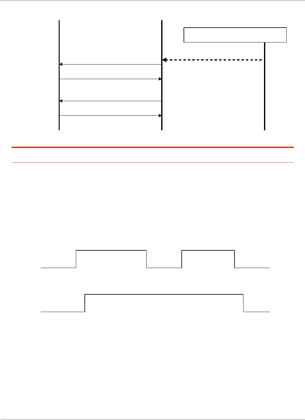
AT Commands Interface Guide for
Firmware 7.52
Error! Use the Home tab to apply Titre 1 to the text that you want to
appear here.
Error! Use the Home tab to apply Titre 2 to the text that you want to
appear here.
Rev. 1.0 Appendix March 7, 2014 70
F9F9F9 protocol wake up frame
F9F9F9 wake up response
DTR on MSC frame
MSC response
Application raises one of the DTR
(or reopen a COM port to make it raised)
Target stops
sending F9F9
flags when
receiving a valid
frame
Target PC MUX driver PC Application
Note: If the valid frame is a DATA frame, the embedded module does not detect any DTR change and
sleeps on again with the PSC frame.
3.2.6.2. Wake up by Sierra Wireless embedded module (DCE)
(unsolicited AT response e.g. 'RING' is to be sent)
The embedded module wakes up the DTE with a 27.010 protocol wake up frame first and then sends
its unsolicited indication.
The protocol preliminary wake up sequence is described below:
b
RX data line
1
2
3
4
TX data line
No data
Valid protocol
frame
F9F9F9F9 wake up
frame (order target to
wake up)
F9F9F9F9 wake up frame acknowledgement (inform
Application that target is waken up)
27.010 Test frame
1: DCE sends 27.010 protocol F9F9F9F9 frame to wake up the asleep Application.
2: DTE replies with 27.010 F9F9F9F9 wake up frame as acknowledgment and waits for a valid frame.
: DCE sends a valid 27.010 test frame in order to have the target stop its acknowledgment.
: DTE stops sending F9F9F9F9 answer after receiving the valid frame.

AT Commands Interface Guide for
Firmware 7.52
Error! Use the Home tab to apply Titre 1 to the text that you want to
appear here.
Error! Use the Home tab to apply Titre 2 to the text that you want to
appear here.
Rev. 1.0 Appendix March 7, 2014 71
The entire "unsolicited string" wake up sequence and sending is described below:
RX data line Wake Up
MSC frames "RING"
Wake Up
MSC frames
Sleep On
MSC frames Sleep On
MSC frames
"RING"
DTR (logical MSC frame sent by the DTE
Busy
10 2 3 310 2
0: The DCE is disturbed with an incoming call.
1: DCE starts sending F9F9F9 wake up frame, waiting for its response and sending a valid test frame
(0x4D ,0x55, 0x58, 0x57, 0x41, 0x4B, 0x45, 0x55, 0x50 = MUXWAKEUP ). (Once waken up, the RI is
sent before the RING string in our case)
2: The unsolicited response message is sent.
8 : After the unsolicited response has been sent, the port is in sleep mode again (no more AT
response and DTR low). Then DCE sends PSC to sleep on and waits for its response.
During the preliminary Wake Up sequence, if no F9F9F9 is received within T3 timer, the embedded
module takes the decision to close all the ports assuming that there is no more CMUX driver in the
remote side.
F9F9F9 protocol wake up frame
F9F9F9 wake up response
Valid frame: test frame "MUXWAKEUP"
Test frame response
An unsolicited AT response ("RING") is to be
sent out
SIERRA WIRELESS Module
(DCE)DTE 27.010 driver
DTE Application
(e.g. Hyperterminal on PC)
PC stops sending F9F9F9
when receiving valid frame
UIH frames
DCE sends "RING" unsolicited string
through 27.010
Protocol PSC Sleep On
PSC response
Preliminary
Wake up phase
DCE "unsolicited
response sending"
phase

AT Commands Interface Guide for
Firmware 7.52
Error! Use the Home tab to apply Titre 1 to the text that you want to
appear here.
Error! Use the Home tab to apply Titre 2 to the text that you want to
appear here.
Rev. 1.0 Appendix March 7, 2014 72
3.3. Support of SIM ToolKit by the M.E.
The table below indicates the commands of the supported letter classes:
Table 1: Support of SIM Toolkit classes (Not supported)
Letter classes
Command/function description
a
Proactive command: GET READER STATUS
Proactive command: PERFORM CARD APDU
Proactive command: POWER ON CARD
Proactive command: POWER OFF CARD
Event download: Card reader status
b
Proactive command: RUN AT COMMAND
c
Proactive command: LAUNCH BROWSER
Event download: Browser termination
d
Soft key support
e
Proactive command: OPEN CHANNEL
Proactive command: CLOSE CHANNEL
Proactive command: RECEIVE DATA
Proactive command: SEND DATA
Proactive command: GET CHANNEL STATUS
Event download: Data available
Event download: Channel status
Table 2: Compatibility between available Terminal Responses and Proactive Commands
Proactive commands
Setup
Menu
Display
Text
Get
Inkey
Get
Input
Setup
Call
Play
Tone
Select
Item
Refresh
Send
SS
Send
SMS
Send
USSD
Setup
event list
Setup idle
mode text
Send
DTMF
Lang
Notification
Terminal
Reponses
(0)
(1)
(2)
(3)
(4)
(5)
(6)
(7)
(8)
(9)
(10)
(11)
(12)
(13)
(14)
(95)
Backward Move
(96)
Command
beyond ME
capabilities
(97)
ME currently
unable to
process
command
(98)
No response
from the user
(99)
SIM session
terminated by
the user
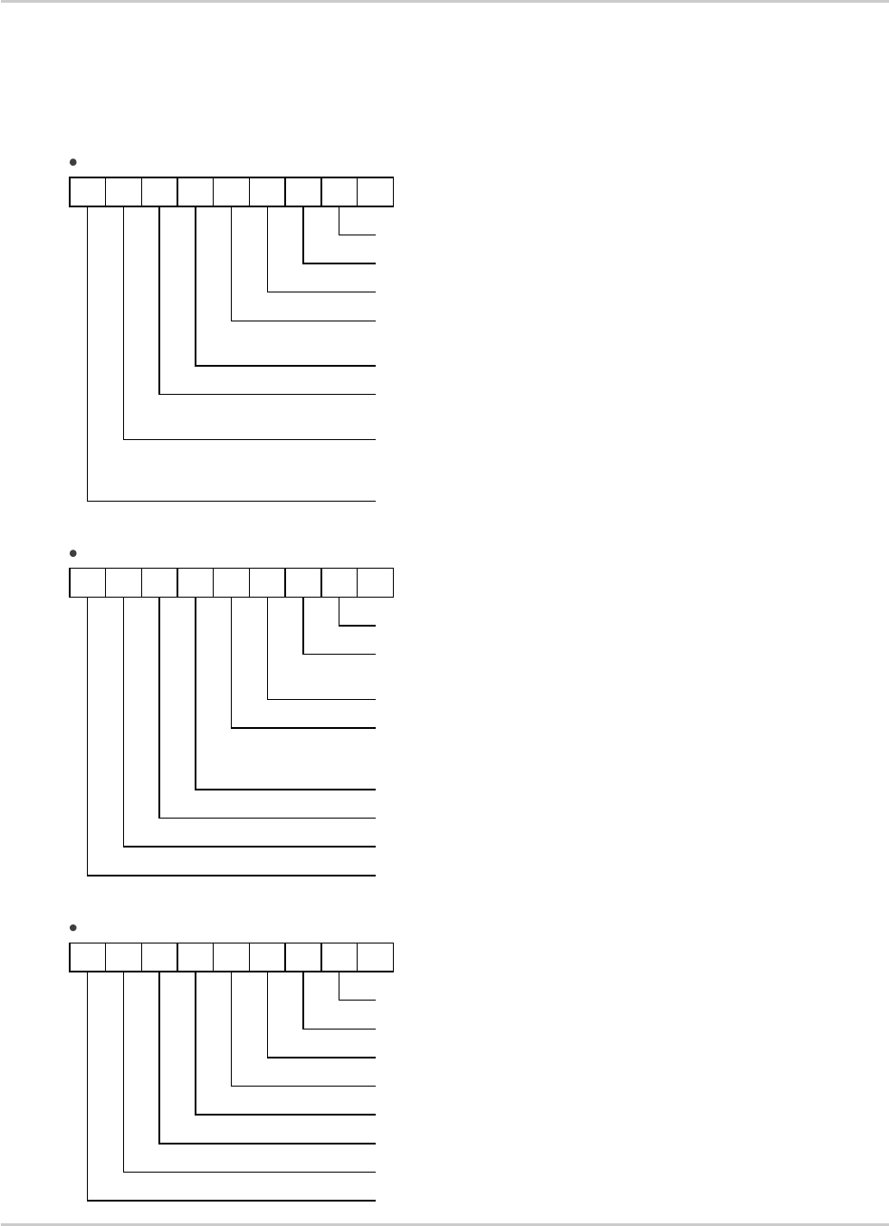
AT Commands Interface Guide for
Firmware 7.52
Error! Use the Home tab to apply Titre 1 to the text that you want to
appear here.
Error! Use the Home tab to apply Titre 2 to the text that you want to
appear here.
Rev. 1.0 Appendix March 7, 2014 73
3.4. Structure of TERMINAL PROFILE
First byte (Download):
b8
b7
b6
b5
b4
b3
b2
b1
Profile download
User choice
SMS-PP data download
Set by product to 1
Cell Broadcast data download
User choice
Menu selection
User choice
‘9E XX’ response code for SIM
data download error
Set by product to 1
Timer expiration
Set by product to 0
USSD string data object
supported in Call Control
User choice
Enveloppe Call Control always
sent to the SIM during
automatic redial mode
User choice
Second byte (Other):
b8
b7
b6
b5
b4
b3
b2
b1
Command result
User choice
Call Control by SIM
User choice
Cell identity included in Call
Control by SIM
User choice
MO short message control by SIM
User choice
Handling of the alpha
identifier according to
subclause 9.1.3
User choice
UCS2 Entry supported
User choice
UCS2 Display supported
User choice
Display of the extension text
User choice
Third byte (Proactive SIM):
b8
b7
b6
b5
b4
b3
b2
b1
Proactive SIM: DISPLAY TEXT
User choice
Proactive SIM: GET INKEY
User choice
Proactive SIM: GET INPUT
User choice
Proactive SIM: MORE TIME
User choice
Proactive SIM: PLAY TONE
User choice
Proactive SIM: POLL INTERVAL
Set by product to 1
Proactive SIM: POLLING OFF
Set by product to 1
Proactive SIM: REFRESH
User choice
AT Commands Interface Guide for
Firmware 7.52
Error! Use the Home tab to apply Titre 1 to the text that you want to
appear here.
Error! Use the Home tab to apply Titre 2 to the text that you want to
appear here.
Rev. 1.0 Appendix March 7, 2014 74
Fourth byte (Proactive SIM):
b8
b7
b6
b5
b4
b3
b2
b1
Proactive SIM: SELECT ITEM
User choice
Proactive SIM: SEND SHORT
MESSAGE
User choice
Proactive SIM: SEND SS
User choice
Proactive SIM: SEND USSD
User choice
Proactive SIM: SET UP CALL
User choice
Proactive SIM: SET UP MENU
User choice
Proactive SIM: PROVIDE LOCAL
INFORMATION (MCC, MNC, LAC,
Cell ID & IMEI)
Set by product to 1
Proactive SIM: PROVIDE LOCAL
INFORMATION (NMR)
Set by product to 1
Fifth byte (Event driven information):
b8
b7
b6
b5
b4
b3
b2
b1
Proactive SIM: SET UP EVENT LIST
Set by product to 1
Event: MT call
Set by product to 1
Event: Call connected
Set by product to 1
Event: Call disconnected
Set by product to 1
Event: Location status
Set by product to 1
Event: User activity
User choice
Event: Idle screen available
User choice
Event: Card reader status
Set by product to 0
Sixth byte: (reserved for Event driven information extensions)
b8
b7
b6
b5
b4
b3
b2
b1
Event: Language selection
Set by product to 1
Event: Browser Termination
Set by product to 0
Event: Data available
Set by product to 0
Event: Channel status
Set by product to 0
RFU, bit = 0
Seventh byte (Multiple card proactive commands) for class "a"
b8
b7
b6
b5
b4
b3
b2
b1
Proactive SIM: POWER ON CARD
Set by product to 0
Proactive SIM: POWER OFF CARD
Set by product to 0
Proactive SIM: PERFORM CARD APDU
Set by product to 0
Proactive SIM: GET READER STATUS
Set by product to 0
AT Commands Interface Guide for
Firmware 7.52
Error! Use the Home tab to apply Titre 1 to the text that you want to
appear here.
Error! Use the Home tab to apply Titre 2 to the text that you want to
appear here.
Rev. 1.0 Appendix March 7, 2014 75
RFU, bit = 0
Eighth byte (Proactive SIM):
b8
b7
b6
b5
b4
b3
b2
b1
Proactive SIM: TIMER
MANAGEMENT (start, stop)
Set by product to 1
Proactive SIM: TIMER
MANAGEMENT (get current value)
Set by product to 1
Proactive SIM: PROVIDE LOCAL
INFORMATION (date, time and
time zone)
Set by product to 1
Binary choice in GET INKEY
User choice
SET UP IDLE MODE TEXT
User choice
RUN AT COMMAND (e.g.. class
"b" is supported)
Set by product to 0
2nd alpha identifier in SET UP
CALL
Set by product to 1
2nd capability configuration
parameter (see 9.1.6)
Set by product to 0
Ninth byte:
b8
b7
b6
b5
b4
b3
b2
b1
Sustained DISPLAY TEXT (see
6.4.1)
Set by product to 0
SEND DTMF command (see 6.4.24)
User choice
Proactive SIM: PROVIDE LOCAL
INFORMATION - BCCH Channel
List coding as in subclause
12.29)
Set by product to 1
Proactive SIM: PROVIDE LOCAL
INFORMATION (language)
Set by product to 1
Proactive SIM: PROVIDE LOCAL
INFORMATION (Timing Advance)
Set by product to 1
Proactive SIM: LANGUAGE
NOTIFICATION
User choice
Proactive SIM: LAUNCH BROWSER
Set by product to 0
RFU, bit = 0
Subsequent bytes:
b8
b7
b6
b5
b4
b3
b2
b1
RFU, bit = 0

AT Commands Interface Guide for
Firmware 7.52
Error! Use the Home tab to apply Titre 1 to the text that you want to
appear here.
Error! Use the Home tab to apply Titre 2 to the text that you want to
appear here.
Rev. 1.0 Appendix March 7, 2014 76
Information about BCCH channel list
(This is an extract of GSM Rec.11.14)
Byte(s)
Description
Length
1
BCCH channel list tag
1
2
Length (X) of bytes following
1
3 to X+2
BCCH channel list
X
8 BCCH channel list
Contents: the list of absolute RF channels for BCCH carriers, as known by the ME from the SYSTEM
INFORMATION messages. The BCCH channel list is composed of one to three BCCH channel sub
lists, each sub list is derived from the set of frequencies defined by reference neighbor cells
description information element or elements. In the latter case the set is the union of the different
subsets defined by the neighbor cells description information elements (see TS 3GPP TS 24.008 [8]).
The length of the BCCH channel list field depends on the length of the received BCCH channel list
derived from the different SYSTEM INFORMATION messages to be considered.
Coding: Each ARFCN (Absolute Radio Frequency Channel Number) is represented by 10 bits. Spare
bit(s) are to be filled with 0.
Bit 8
Bit 7
Bit 6
Bit 5
Bit 4
Bit 3
Bit 2
Bit 1
Byte 1
ARFCN#1 (high part)
Byte 2
ARFCN#1 (low part)
ARFCN#2 (high part)
Byte 3
ARFCN#2 (low part)
ARFCN#3 (high part)
…
…
Byte X-1
ARFCN#m-1 (low part)
ARFCN#m (high part)
Byte X
ARFCN#m (low part)
Spare bit
(0)
Spare
bit(0)
SIM applications should take into account that early implementations of SIM application toolkit may
have coded this field differently, because of an inconsistency between the content and the coding of
this element in previous versions of 11.14. The SIM is able to identify Mes that are using the coding
described above by evaluating the indication "BCCH Channel List coding" in the TERMINAL
PROFILE command.

AT Commands Interface Guide for
Firmware 7.52
Error! Use the Home tab to apply Titre 1 to the text that you want to
appear here.
Error! Use the Home tab to apply Titre 2 to the text that you want to
appear here.
Rev. 1.0 Appendix March 7, 2014 77
3.5. Command Type and Next Action Indicator.
This table has been extracted from the GSM Technical specification 11.14.
Value
Name
Used for Type
of Command
coding
used for Next
Action Indicator
coding
'00'
-
-
'01'
REFRESH
X
'02'
MORE TIME
X
'03'
POLL INTERVAL
X
'04'
POLLING OFF
X
'05'
SET UP EVENT LIST
X
'10'
SET UP CALL
X
X
'11'
SEND SS
X
X
'12'
SEND USSD
X
X
'13'
SEND SHORT MESSAGE
X
X
'14'
SEND DTMF
X
‘15’
LAUNCH BROWSER class "c"
X
'20'
PLAY TONE
X
X
'21'
DISPLAY TEXT
X
X
'22'
GET INKEY
X
X
'23'
GET INPUT
X
X
'24'
SELECT ITEM
X
X
'25'
SET UP MENU
X
X
'26'
PROVIDE LOCAL INFORMATION
X
'27'
TIMER MANAGEMENT
X
'28'
SET UP IDLE MODEL TEXT
X
X
'30'
PERFORM CARD APDU class "a"
X
X
'31'
POWER ON CARD class "a"
X
X
'32'
POWER OFF CARD class "a"
X
X
'33'
GET READER STATUS class "a"
X
X
'34'
RUN AT COMMAND class "b"
X
‘35’
LANGUAGE NOTFIICATION
X
‘40’
OPEN CHANNEL class "e"
X
X
‘41’
CLOSE CHANNEL class "e"
X
X
‘42’
RECEIVE DATA class "e"
X
X
‘43’
SEND DATA class "e"
X
X
‘44’
GET CHANNEL STATUS class "e"
X
X
'81'
End of the proactive session
not applicable
X

AT Commands Interface Guide for
Firmware 7.52
Error! Use the Home tab to apply Titre 1 to the text that you want to
appear here.
Error! Use the Home tab to apply Titre 2 to the text that you want to
appear here.
Rev. 1.0 Appendix March 7, 2014 78
3.6. Coding of Alpha Fields in the SIM for UCS2
The coding can take one of the three following structures, or GSM default alphabet. If the ME
supports UCS2 coding of alpha fields in the SIM, it will support all three coding schemes for character
sets containing 128 characters or less. For character sets containing more than 128 characters, the
ME will at least support the first coding scheme. Within a record, only one coding scheme, either GSM
default alphabet, or one of the three described below, can be used.
1. If the first byte in the alpha string is ‘0x80’, then the other bytes are 16 bit UCS2 characters.
The most significant byte (MSB) of the UCS2 character is coded in the lower numbered byte of
the alpha field, and the less significant byte (LSB) of the UCS2 character is coded in the higher
numbered alpha field byte. In other words, byte 2 of the alpha field contains the most significant
byte (MSB) of the first UCS2 character, and byte 3 of the alpha field contains the less significant
byte (LSB) of the first UCS2 character (as shown below). Unused bytes shall be set to ‘FF’: if the
alpha field has an even length in bytes, the last (unusable) byte will be set to ‘FF’.
Example 1
Byte 1
Byte 2
Byte 3
Byte 4
Byte 5
Byte 6
Byte 7
Byte 8
Byte 9
‘80’
Ch1MSB
Ch1LSB
Ch2MSB
Ch2LSB
Ch3MSB
Ch3LSB
‘FF’
‘FF’
2. If the first byte of the alpha string is ‘0x81’, then the 2nd byte contains a value indicating the
number of characters in the string. The 3rd byte contains an 8 bit number which defines bits 15 to
8 of a 16 bit base pointer, where bit 16, and bits 7 to 1 would be set to zero. These sixteen bits
represent a base pointer to a "half-page" in the UCS2 code space, to be used with some or all of
the remaining bytes in the string. The 4th and subsequent bytes in the string contain coding as
follows:
if bit 8 of the byte is set to zero, the remaining bits of the byte contain a GSM Default Alphabet
character
if bit 8 of the byte is set to one, the remaining bits are an offset value to add to the 16 bit base
pointer defined by byte 3, and the resulting 16 bit value is a UCS2 code point, and defines a
UCS2 character.
Example 2
Byte 1
Byte 2
Byte 3
Byte 4
Byte 5
Byte 6
Byte 7
Byte 8
Byte 9
‘81’
‘05’
‘13’
‘53’
‘95’
‘A6’
‘28’
‘FF’
‘FF’

AT Commands Interface Guide for
Firmware 7.52
Error! Use the Home tab to apply Titre 1 to the text that you want to
appear here.
Error! Use the Home tab to apply Titre 2 to the text that you want to
appear here.
Rev. 1.0 Appendix March 7, 2014 79
In the example above
Byte 2 indicates there are 5 characters in the string
Byte 3 indicates bits 15 to 8 of the base pointer, and indicates a bit pattern of
0hhh shah h000 0000 as the 16 bit base pointer number. Bengali characters for example start
at code position 0980 (0000 1001 1000 0000), which is indicated by the coding ‘13’ in byte 3
(shown by the italicized underlined digits).
Byte 4 indicates GSM Default Alphabet character ‘53’, e.g.. "S".
Byte 5 indicates a UCS2 character offset to the base pointer of ‘15’, expressed in binary as
follows 001 0101, which, when added to the base pointer value results in a sixteen bit value of
0000 1001 1001 0101, e.g.. ‘0995’, which is the Bengali letter KA.
Byte 8 contains the value ‘FF’: as the string length is 5, this a valid character in the string,
where the bit pattern 111 1111 is added to the base pointer, yielding to a sixteen bit value of
0000 1001 1111 1111 for the UCS2 character (that is ‘09FF’).
Byte 9 contains the padding value OxFF.
3. If the first byte of the alpha string is set to ‘0x82’, then the 2nd byte contains the length of the
string (number of characters).The 3rd and 4th bytes contain a 16 bit number which defines the
complete 16 bit base pointer to a "half-page" in the UCS2 code space, for use with some or all of
the remaining bytes in the string. The 5th and subsequent bytes in the string contain coding as
follows:
if bit 8 of the byte is set to zero, the remaining seven bits of the byte contain a GSM Default
Alphabet character,
if bit 8 of the byte is set to one, the remaining seven bits are an offset value added to the base
pointer defined in bytes 3 and 4, and the resulting 16 bit value is a UCS2 code point, and
defines a UCS2 character.
Example 3
Byte 1
Byte 2
Byte 3
Byte 4
Byte 5
Byte 6
Byte 7
Byte 8
Byte 9
‘82’
‘05’
‘05’
‘30’
‘2D’
‘82’
‘D3’
‘2D’
‘31’
In the example above:
Byte 2 indicates there are 5 characters in the string
Bytes 3 and 4 contain a 16 bit base pointer number of ‘0530’, pointing to the first character of
the Armenian character set.
Byte 5 contains a GSM Default Alphabet character of ‘2D’, which is a dash "-".
Byte 6 contains a value ‘82’, which indicates it is an offset of ‘02’ added to the base pointer,
resulting in a UCS2 character code of ‘0532’, which represents Armenian character Capital
BEN.
Byte 7 contains a value ‘D3’, an offset of ‘53’, which when added to the base pointer results in
a UCS2 code point of ‘0583’, representing Armenian Character small PIWR.

AT Commands Interface Guide for
Firmware 7.52
Error! Use the Home tab to apply Titre 1 to the text that you want to
appear here.
Error! Use the Home tab to apply Titre 2 to the text that you want to
appear here.
Rev. 1.0 Appendix March 7, 2014 80
3.7. Specifications of Power Down Control
mechanism through serial Ports (physical
RS232 ports or virtual CMUX ports)
3.7.1. What is new on X55 and further software releases
V24 Sleep mode and Sierra Wireless 32K mode used to be a one and only functionality. Since v24
now supports several ports (physical or virtual), Sierra Wireless products are allowed to enter 32K low
consumption mode only when all of these ports are individually ready to enter such a mode.
3.7.2. Definitions
3.7.2.1. Serial Port Sleep Mode State
This mode reflects the particular V24 state of a port (physical or virtual) regarding the possibility to
enter or not 32K low consumption mode.
This mode is entered automatically when:
The port is in AT command mode. (no GSM/GPRS communication is in progress on it).
No AT response is to be sent to the DTE.
The connected DTE is no more ready to communicate on it (meaning DTE sets DTR low).
This mode is left automatically when some unsolicited responses are to be sent to the DTE.
The connected DTE is ready to communicate on it (meaning DTE sets DTR high).
CTS is set when in this mode, the DCE does not allow the DTE to send data to the involved serial port
(meaning low on that port).
3.7.2.2. Serial Ports Sleep Mode Global State
This mode reflects the state of all the internal serial ports regarding their ability to enter 32K low
consumption mode.
It is a Boolean (asleep or not) that authorizes or not GSM/GPRS protocol and Hardware Layers to
enter 32K low consumption mode.
This mode is entered and left automatically depending on the state of all currently available serial
ports (virtual or physical).
Global V24 sleep mode is entered when all v24 available ports are in sleep mode state.
Global V24 sleep mode is left when at least one of the v24 available ports is not in sleep
mode state.

AT Commands Interface Guide for
Firmware 7.52
Error! Use the Home tab to apply Titre 1 to the text that you want to
appear here.
Error! Use the Home tab to apply Titre 2 to the text that you want to
appear here.
Rev. 1.0 Appendix March 7, 2014 81
3.7.2.3. Sierra Wireless 32K Low Consumption Mode
This mode is based on a slower clock (32KHz) that is used instead of 13MHz clock. Most of hardware
blocks are stopped. It is aimed at reducing the power consumption.
This mode is entered and left automatically if the feature is allowed.
To activate this mode, the "+W32K" AT command must be used.
It is authorized or not by peripherals (such as UARTs, Buses, …) and mainly driven by GSM/GPRS
protocols and Hardware Layers: this mode is entered when no GSM/GPRS activity is required (no
communication is in progress, no paging is in progress, …).
Regarding UARTs and serial ports activity, 32K low consumption mode may be entered as soon as
V24 sleep mode global state is "asleep".
Sierra Wireless embedded module decides on its own to leave 32K low consumption at each
GSM/GPRS paging occasion.
During, this little time (which is operator dependant), UARTs are activated again so that DTR state
changes can be processed.
When this mode is activated, no data can be exchanged on RXD and TXD lines. Only embedded
module status changes can be monitored (DTR and RTS changes) by the DCE.
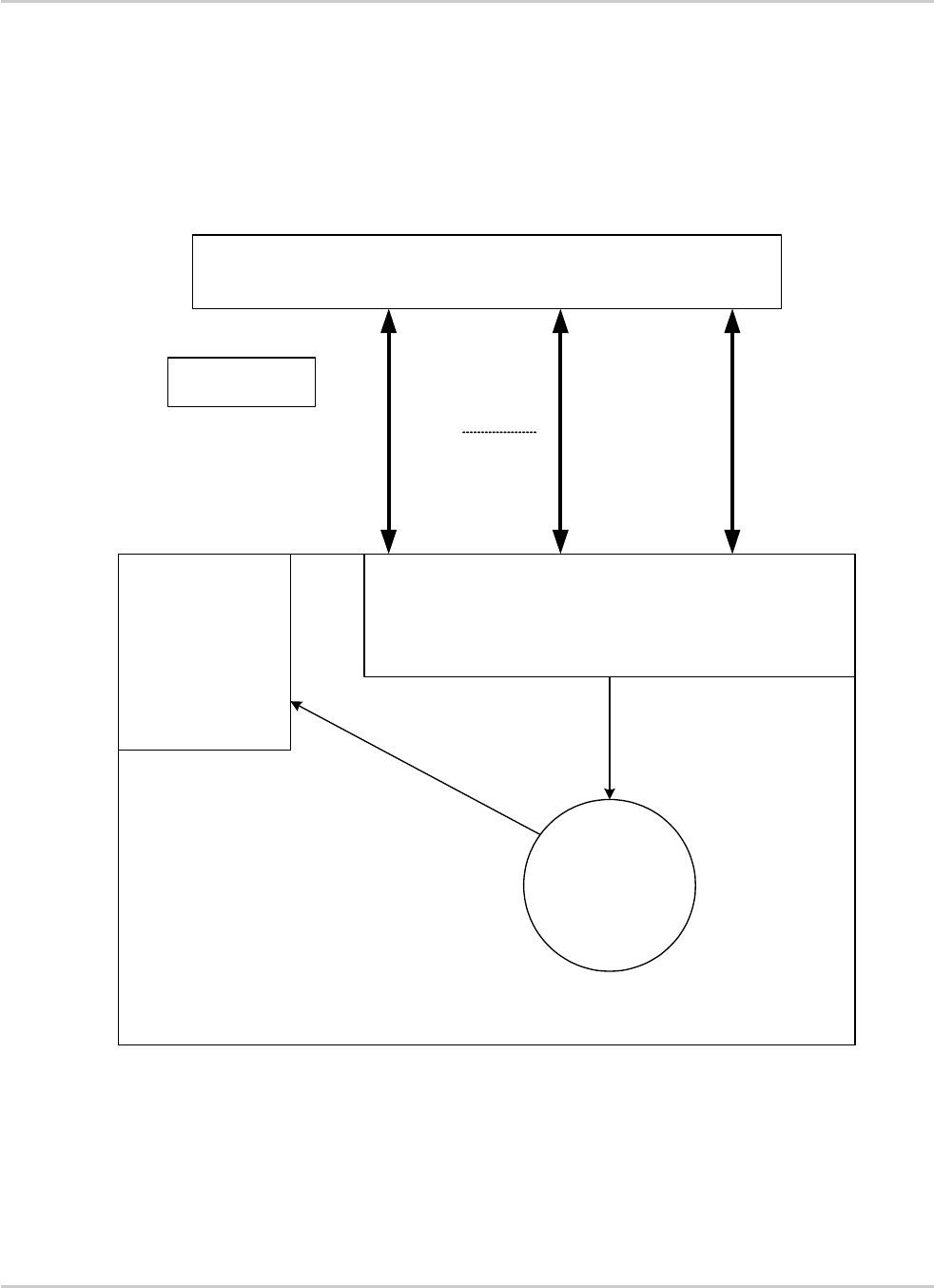
AT Commands Interface Guide for
Firmware 7.52
Error! Use the Home tab to apply Titre 1 to the text that you want to
appear here.
Error! Use the Home tab to apply Titre 2 to the text that you want to
appear here.
Rev. 1.0 Appendix March 7, 2014 82
3.7.3. Summary
To summarize the 3 definitions, the following schematics describe the functional links between, serial
port sleep mode single state manager, serial ports sleep mode global state manager and W32K
sleep mode manager.
Customer Application
Customer enables
SIERRA WIRELESS
32K low power mode
consumption
AT+W32K=1
Manage each serial port sleep mode state (asleep or not)
SIERRA
WIRELESS 32K
low power mode
manager Serial link driver
V24
is
ASLEEP or NOT
SIERRA WIRELESS
Module
Authorize or
not Low power
mode
Update Global
Serial Sleep
mode state
Serial Port 1
Serial Port N-1 Serial Port N

AT Commands Interface Guide for
Firmware 7.52
Error! Use the Home tab to apply Titre 1 to the text that you want to
appear here.
Error! Use the Home tab to apply Titre 2 to the text that you want to
appear here.
Rev. 1.0 Appendix March 7, 2014 83
3.7.4. Case of Single Serial Port Use
This section describes the expected behavior for a single serial port (physical or virtual). Please
remember that this behavior is independent of W32K feature activation.
3.7.4.1. Sleep on Procedure
In order to place a serial port in Sleep Mode state, the DTE just has to drop its DTR signal to indicate
that it is Busy. Then, Sierra Wireless embedded module (DCE) sets the DTE CTS low.
1
3
2
DTR (DTE)
Clear to Send
Busy
RX data line (DTE)
Clear to Send
CTS (DTE)
Ready
1: The application drops its DTR to indicate a busy state
2: Sierra Wireless embedded module (DCE) detects DTR drop and check if there are still AT
responses to send on that port.
8 : When DTR is low and there are no more AT response, the DCE sets the application (DTE)
CTS low. (At this point, the associated serial port is in Sleep Mode state)
Note: While in data mode, the CTS does not follow the DTR.

AT Commands Interface Guide for
Firmware 7.52
Error! Use the Home tab to apply Titre 1 to the text that you want to
appear here.
Error! Use the Home tab to apply Titre 2 to the text that you want to
appear here.
Rev. 1.0 Appendix March 7, 2014 84
3.7.4.2. Wake up Procedures
3.7.4.2.1. On DTE initiative: Wake up by DTR Raise
DTR (DTE)
Busy
CTS (DTE)
Not Clear to Send
Clear to Send
Ready
1
2 3
1: The application raises its DTR signal to indicate a ready state (meaning DTE wants to
communicate with the DCE).
2: Sierra Wireless embedded module (DCE) takes into account the DTR signal change. (MSR IRQ for
physical port or protocol frame for CMUX)
8 : V24 triggers the DTE CTS signal to allow AT commands again. (CTS is high)
3.7.4.2.2. On DCE initiative: Wake up by AT unsolicited indications ( e.g.
'RING' indicator)
CTS (DTE)
RX data line (DTE) "RING" "RING"
Not Clear to Send
BusyDTR (DTE)
1 12 2
1: An incoming call occurs. Consequently unsolicited indications ("RING") are sent to the DTE.
8 : As soon as unsolicited indication has been sent, the port switches back to sleep mode state
(as long as there is no more AT command response to send and that DTR remains High)
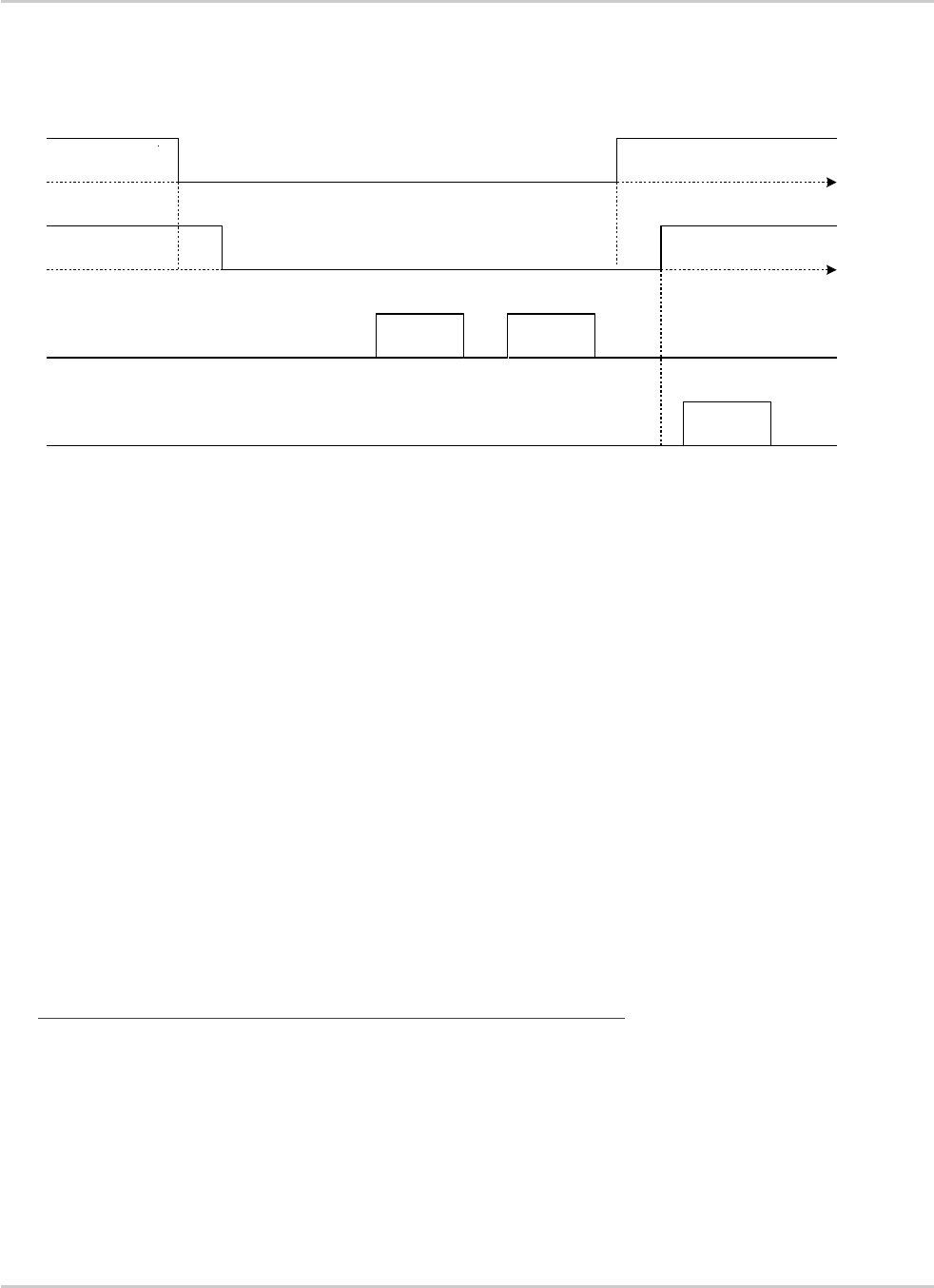
AT Commands Interface Guide for
Firmware 7.52
Error! Use the Home tab to apply Titre 1 to the text that you want to
appear here.
Error! Use the Home tab to apply Titre 2 to the text that you want to
appear here.
Rev. 1.0 Appendix March 7, 2014 85
3.7.4.3. Complete Sequence Behavior
DTR (DTE)
CTS (DTE)
TX data line (DTE)
RX data line (DTE)
Not Clear to Send
Clear to Send Clear to Send
Ready
Ready
Busy
"RING" "RING"
time
time
time
time
"ATA"
"OK"
1
2 3
4 4
5 6
7
8
1: The application (DTE) drops its DTR to indicate to DCE a busy state
2: Sierra Wireless embedded module (DCE) computes and check if there are still AT responses to
send on that port.
3: Since no more AT response is to be sent, the DCE sets CTS to low so that application (DTE)
can not send any data to the Sierra Wireless embedded module (DCE). At this stage, the
associated serial port is in Sleep Mode state.
4: An incoming call occurs. As a consequence, unsolicited AT indications (e.g. "RING") are sent
to the DTE.
Note that even if RING are sent, Serial Port remains in Sleep Mode state.
5: Customer application (DTE) wants to answer to "RING" unsolicited AT indications. It MUST
raise first DTR to wake up the serial Port.
6: On Sierra Wireless embedded module (DCE), detection of DTR rise informs that customer
application (DTE) wants to get out from sleep mode state. DCE sets CTS high so that
customer application (DTE) can send again data to Sierra Wireless embedded module.
Note that at this stage, Serial Port is no more in Sleep Mode state.
7: Customer application (DTE) replies to RING indication with "ATA" command.
8: Sierra Wireless embedded module (DCE) acknowledges and processes the command.
Note that this behavior applies whether W32K is activated or not.

AT Commands Interface Guide for
Firmware 7.52
Error! Use the Home tab to apply Titre 1 to the text that you want to
appear here.
Error! Use the Home tab to apply Titre 2 to the text that you want to
appear here.
Rev. 1.0 Appendix March 7, 2014 86
3.7.4.4. Transition State (from Asleep to Awake)
When unsolicited AT responses are to be sent (e.g. "RING" indication), V24 software elements enters
a transition state that places the global sleep mode state in the "Awake State". Thus, until unsolicited
responses are sent, the Sierra Wireless embedded module can not enter Low power mode
consumption (W32K). As a consequence, RTS signal MUST remain High to allow the transmission of
the unsolicited response.
Note: Mind that unsolicited responses are broadcasted on all available serial ports
when unsolicited
responses are to be sent (e.g. "RING") on a serial port and signals are not managed (e.g. RS232
cable is disconnected whereas associated V24 serial port is still registered) then Sierra Wireless
embedded module is not allowed to enter W32K low power mode consumption.
3.7.5. Case of Several Serial Ports Use
The behavior specified in section

AT Commands Interface Guide for
Firmware 7.52
Error! Use the Home tab to apply Titre 1 to the text that you want to
appear here.
Error! Use the Home tab to apply Titre 2 to the text that you want to
appear here.
Rev. 1.0 Appendix March 7, 2014 87
Case of Single Serial Port Use applies to each of the activated serial ports (physical or virtual e.g.
CMUX).
Note: When Sierra Wireless 32K low power mode is activated (AT+W32K=1), embedded module really
enters low power mode when all activated serial ports are set to sleep mode state.
3.7.6. UART2 Exception (on all embedded modules)
Physical block of the UART2 only provides embedded module with RX/TX and CTS/RTS signals so
that DTR can not be wired on UART2 serial port.
Since only RXD/TXD and RTS/CTS are available, there is no way to enter/leave sleep mode on this
particular port.
Thus, UART2 is not scanned to manage global Serial Sleep mode state. As a consequence, data can
be lost on UART2 if W32k is activated.
Warning: When only UART2 is activated, activation of W32K mode is forbidden.
Note: When emulating one (or more) virtual port(s) over UART2 using CMUX feature, it is then possible to
use W32K mode.

AT Commands Interface Guide for
Firmware 7.52
Error! Use the Home tab to apply Titre 1 to the text that you want to
appear here.
Error! Use the Home tab to apply Titre 2 to the text that you want to
appear here.
Rev. 1.0 Appendix March 7, 2014 88
3.8. Description of Multi-Flow Behavior
Multi-flows allow the embedded module to treat commands from various sources (or flows):
UART ports
USB port
embedded applications.
CMUX virtual ports
AT commands are organized in classes , and multi-flow allows the simultaneous execution of
commands of different classes coming from the possible sources:
commands belonging to the same class can not be treated as the same time. When a
command of a class is treated, the embedded module will respond "busy" to any command of
the same class until the first command processing has completed.
when a flow is waiting for the treatment of a command, it is busy until the command execution
completion.
Example:
The embedded module receives a command of class AT_CLASS_PHONEBOOK on UART1. The
processing of the command starts, and a response from the phonebook entity is expected. No other
command of the AT_CLASS_PHONEBOOK class can be processed, and the UART1 port is busy.
The embedded module receives then a command from USB port, of another class. It is able to
immediately process this second command.
When the phonebook entity answers, the first command’s processing completes. UART1 port and
AT_CLASS_PHONEBOOK class are released.
Notes:
concatenation of commands remains possible,
the Repeat command (A/) runs independently for each flow,
an embedded application or "+WMFM" AT command may change data redirection.
3.8.1. Commands Classes
There are 27 commands classes, presented in the array below:
Class name
Related commands
AT_CLASS_A_SLASH
A/
AT_CLASS_COM
+CHLD, +VTD, +VTS, +WATH, A, D, DL, H, O
AT_CLASS_CPHS
+CPHS, +WALS, +WMBN
AT_CLASS_DATA
+CRLP, +DOPT
AT_CLASS_FAX
+FBOR, +FBUF, +FCQ, +FCR, +FDCC, +FDIS, +FPHCT, +FRH, +FRM, +FRS,
+FTH, +FTM, +FTS, FLID
AT_CLASS_GPRS
+CGACT, +CGANS, +CGATT, +CGAUT, +CGCLA, +CGDATA, +CGDCONT,
+CGERE, +CGPAD, +CGQMI, +CGQRE, +CGREG, +CGSMS, +GCAP,
+WGPRS;+CGCMOD
AT_CLASS_LOCATION
+WLOC

AT Commands Interface Guide for
Firmware 7.52
Error! Use the Home tab to apply Titre 1 to the text that you want to
appear here.
Error! Use the Home tab to apply Titre 2 to the text that you want to
appear here.
Rev. 1.0 Appendix March 7, 2014 89
Class name
Related commands
AT_CLASS_MAIN
%D, &C, &D, &E, &F, &S, &T, &V, &W, +ADC, +ATGH;+CALA, +CBST, +CCLK,
+CEER, +CGMI, +CGMM, +CGMR, +CGSN, +CICB, +CIND, +CLAE;+CLAN;+CLCC,
+CLVL;+CMEC, +CMEE, +CMER, +CMUT, +CMUX+CPAS, +CR, +CRC, +CREG,
+CRMP, +CRSL, +CSCS, +CSNS, +CSTA;+CSVM, +ECHO, +FCLASS, +ICF, +IFC,
+ILRR, +IPR, +SIDET, +SPEAK, +VGR, +VGT, +VIP, +W32K, +WAC,
+WADF;+WBCM, +WCCS, +WCDM, +WCDP, +WCFM, +WCTM, +WDGR; +WDGT;
+WDOP, +WDTMF, +WDWL, +WFM, +WHWV, +WIMEI, +WIND, +WIOM, +WIOR,
+WIOW, +WLCK, , +WMSN, +WPCS, +WREGC;+WRIM, +WRST, +WSCAN,
+WSST, , +WSTR, +WSVN, +WTONE, +WVR, E, I, Q, S, V, Z, +WMFM, +WOPEN,
+WCOS
AT_CLASS_NETWORK
+CCED, +COPN, +COPS, +CPLS, +CPOL, +CSQ, +WMBS, +WOPN, +WOLM
AT_CLASS_PHONEBOOK
+CNUM, +CPBF, +CPBN, +CPBP, +CPBR, +CPBS, +CPBW, +WAIP, +WDCP
AT_CLASS_PHONEBOOK
WPGW, WPGR, WPGS
AT_CLASS_POFF
+CFUN, +CPOF, +WBHV
AT_CLASS_RIL
+CRSM, +CSIM
AT_CLASS_RS
+CPWL
AT_CLASS_SECURITY
+CLCK, +CPIN, +CPIN2, +CPINC, +CPWD
AT_CLASS_SIM
+CCID, +CIMI, +WLPR, +WLPW
AT_CLASS_SMS
+CMGD, +CMGF, +CMGL, +CMGR, +CMGS, +CMGW, +CMSS, +CNMA, +CNMI,
+CPMS, +CRES, +CSAS, +CSCA, +CSCB, +CSDH, +CSMP, +CSMS, +WCBM,
+WMGO, +WMSC, +WUSS, +WMCP
AT_CLASS_SS
+CACM, +CAMM, +CAOC, +CCFC, +CCUG, +CCWA, +CKPD, +CLIP, +CLIR,
+COLP, +CPUC, +CSSN, +CUSD
AT_CLASS_STLK
+STGI, +STGR, +STIN, +STSF
AT_CLASS_V24B
%C, \N, +DR, +DS
3.8.2. Remark on Error 536
When a class is locked and when another command belonging to the same class arrives, the
embedded module answers +CME ERROR: 536.

AT Commands Interface Guide for
Firmware 7.52
Error! Use the Home tab to apply Titre 1 to the text that you want to
appear here.
Error! Use the Home tab to apply Titre 2 to the text that you want to
appear here.
Rev. 1.0 Appendix March 7, 2014 90
3.9. USB CDC feature
3.9.1. Software Specification
The embedded module implements an Abstract Control Modem as specified in the Communication
Device Class 1.1 specification, therefore a host can use the embedded module either as an
embedded module device or as a virtual communication port (VCOM).
3.9.2. Managing the USB Feature
3.9.2.1. Enabling the USB Port
To activate the USB feature, in CDC mode, the application must send the AT+WMFM=0,1,3
command to the embedded module. The embedded module replies:
OK if the USB stack successfully started,
+CME ERROR: 3 if the USB stack failed to start.
From here there is 2 possibilities:
1 – The embedded module is wired to the host, the device enumeration is done: if the enumeration
is successfully completed, a VCOM and a embedded module device (viewable in the devices
manager) are created at the host side otherwise the failure is notified to the user (by the host).
2 – The embedded module is not wired to the host: the USB stack is waiting for the USB cable
plugging. As soon as the cable is plugged, the enumeration stage described above starts.
3.9.2.2. Disabling the USB Port
To deactivate the USB feature, the application must send the AT+WMFM=0,0,3 command by using
either the UART1 or the UART2.
Two cases are supported:
1- The USB stack is running in CDC mode: if the stack is stopped successfully, the embedded
module replies OK, otherwise it replies '+CME ERROR: 3' (note the USB stack is still running
in CDC mode).
2- The USB stack is stopped: the embedded module replies unconditionally '+CME ERROR: 3'.
An embedded module reset, whatever its origin, stops the USB stack. If the user has saved the USB
CDC configuration in EEPROM, the stack will be restarted while the embedded module is rebooting.
Stopping the USB stack and then disabling the CDC device implies that the VCOM and embedded
module are getting unavailable at the host side. The applications using these resources must be
closed since the piece of software drivers they are using no longer exists.
3.9.2.3. USB low power mode
USB Suspend/Resume states are supported as described in USB specifications.
USB port enters into a Suspend state when no more activity is detected on the bus.
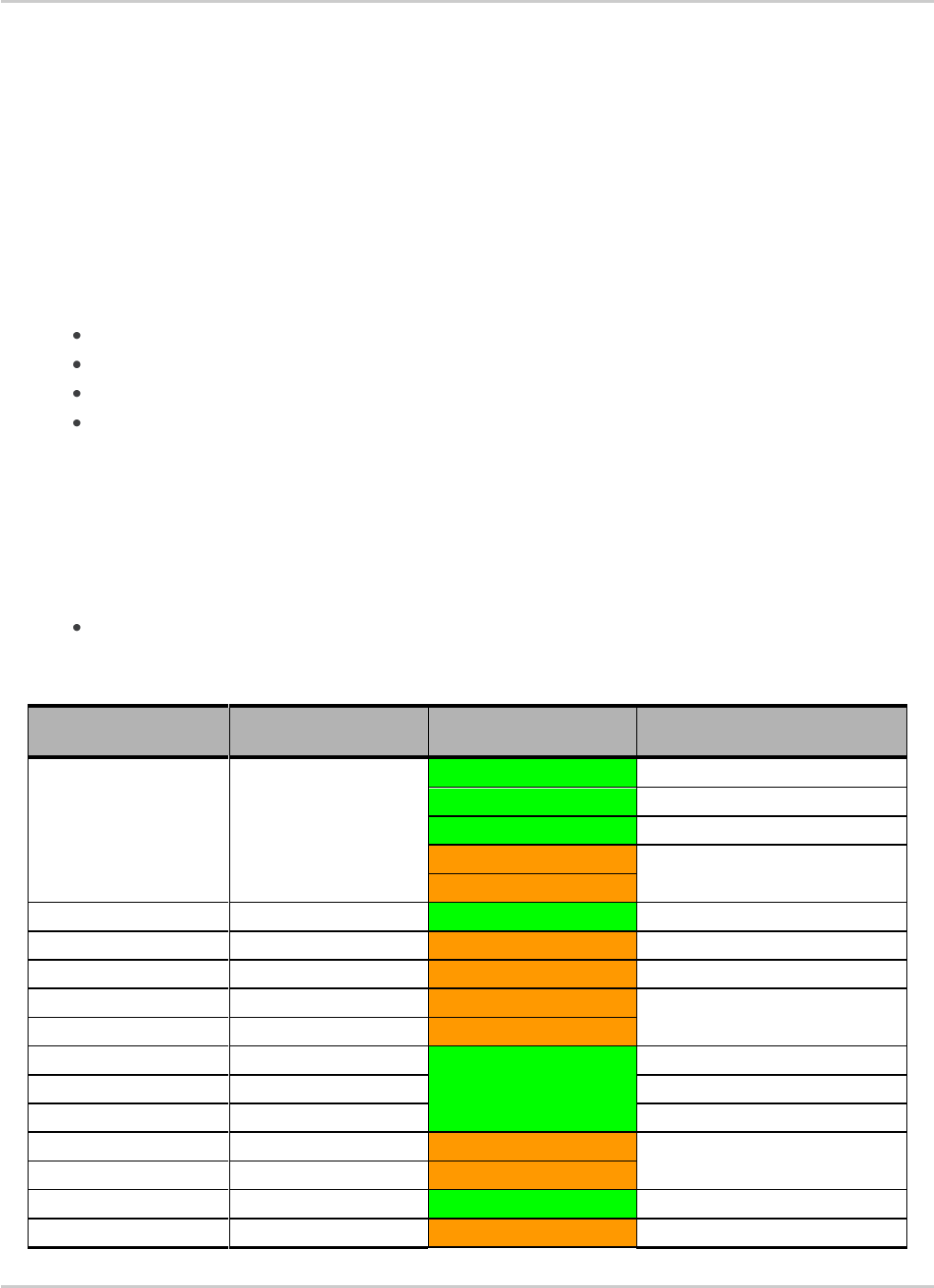
AT Commands Interface Guide for
Firmware 7.52
Error! Use the Home tab to apply Titre 1 to the text that you want to
appear here.
Error! Use the Home tab to apply Titre 2 to the text that you want to
appear here.
Rev. 1.0 Appendix March 7, 2014 91
USB port enters into a Resume state if any activity is detected on the bus.
3.9.3. USB Restriction
The Sierra Wireless implementation does not currently support the remote wake up feature.
3.9.4. Supported Applications
In a general way all the applications using a serial port can be used on the USB serial port. Some
tests have been conducted with the following applications:
hyper terminal
Y-Modem / X-Modem / Z-Modem
TMT
DockLight
Delrina Fax (select the Sierra Wireless USB embedded module)
3.9.5. AT Command Restrictions
When using the USB port to manage the embedded module the following commands are either not
supported or have a specific behavior.
AT+ICF - character format
AT+ICF? The list of supported USB emulated serial port settings are stated (highlighted in green) in
the following table. The settings highlighted in orange must not be used.
Data number
Stop number
Kind of Parity
AT+ICF? responses
8
1
None
+ICF: 3,4
Odd
+ICF: 2,0
Even
+ICF: 2,1
Mark
Not supported always replies:
"+ICF: 2,4"
Space
8
2
None
+ICF: 1,4
Odd
+ICF: 2,0
Even
+ICF: 2,1
Mark
Not supported always replies:
"+ICF: 2,4"
Space
7
1
None
+ICF: 6,4
Odd
+ICF: 5,0
Even
+ICF: 5,1
Mark
Not supported always replies:
"+ICF: 5,4"
Space
7
2
None
+IFC: 4,4
Odd
+IFC: 5,0

AT Commands Interface Guide for
Firmware 7.52
Error! Use the Home tab to apply Titre 1 to the text that you want to
appear here.
Error! Use the Home tab to apply Titre 2 to the text that you want to
appear here.
Rev. 1.0 Appendix March 7, 2014 92
Data number
Stop number
Kind of Parity
AT+ICF? responses
Even
+IFC: 5,1
Mark
Not supported always replies:
"+ICF: 5,4"
Space
8 or 7
1.5
None
Not supported always replies
"+ICF: 2,4"
Odd
Even
Mark
Space
AT+ICF=? will provide the same responses as it is sent on UART1 or 2.
AT+CFUN=1 - embedded module reset
Normally (when using UART1/2 to manage the embedded module) the OK response is sent to the
application after the embedded module reset.
When using the emulated serial port a such response is not provided! In addition the embedded
module reset will cause the USB stack stopping. From the host’s point of view it is similar to a USB
cable disconnection. As consequence the host is going to un-install the Sierra Wireless USB driver
and the application will reference a non valid driver.
AT+WDWL - firmware download
This command is unsupported when using the USB serial emulated port.

Rev. 1.0 Appendix March 7, 2014 93
4. Interoperability
All the commands listed below are only used for interoperability with other applications. They have no
action and always reply OK.
Command
Responses
ATB
OK
ATC
OK
ATG
OK
ATL
OK
ATM
OK
ATN
OK
ATP
OK
ATT
OK
ATW
OK
ATX
OK
ATY
OK
AT\K
OK
AT&E
OK
AT&G
OK
AT&K
OK
AT&P
OK
AT&Q
OK
AT&R
OK
AT&Y
OK
AT+GOI
OK
AT+GCI
OK

Rev. 1.0 Appendix March 7, 2014 94
5. AirPrime Management Services
The commands listed in the following table are available using the AirPrime Management Services.
Command
&C
&D
&S
&V
&W
+ADC
+CFUN
+CGCLASS
+CGDCONT
+COPS
+CPIN2
+CPINC
+ICF
+IFC
+IPR
+WAIP
+WASR
+WBCM
+WBHV
+WCPS
+WDSO
+WGPRS
+WHCNF
+WIPS
+WOPEN
+WOPENRES
+WPPP
E
I
Q
