JBL E250P E150/250P (120V) OM User Manual To The 5205fa50 Daa9 42c6 B7da F31ecfbdb50c
User Manual: JBL E250P to the manual
Open the PDF directly: View PDF ![]() .
.
Page Count: 31
Models:
Northridge™ E-Series E250P
Performance Series P12SW
Powered Subwoofers
Service Manual
JBL Consumer Products
250 Crossways Park Dr.
Woodbury, New York 11797 Rev3 4/2006

- CONTENTS -
BASIC SPECIFICATIONS …………….……..…………..1
SAFETY INFORMATION …………….……..….………..2
E250P PACKING……..………………….….….….……...3
P12SW PACKING……..……………………….…………4
DETAILED SPECIFICATIONS ……….……..…………..5
CONNECTIONS………………………...……..…...…..…6
OPERATION ……..………………….……...…….….…...9
BASIC TROUBLESHOOTING…………………………..10
E250P EXPLODED VIEW/PARTS LIST……………….11
P12SW EXPLODED VIEW/PARTS LIST……….……..12
TEST SET-UP AND PROCEDURE….…………………13
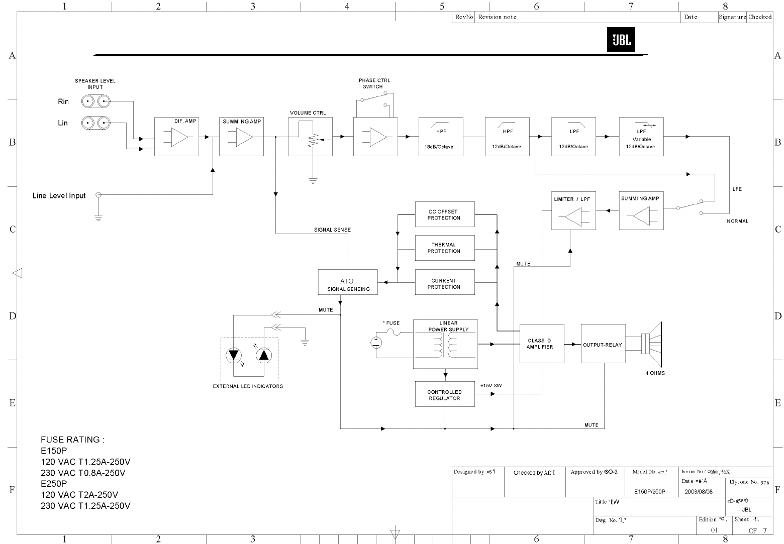
AMPLIFIER BLOCK DIAGRAM…………………………14
E250P BULLETIN JBL2005-01..……………..… ……..15
E250P/P12SW TECH TIP JBLTT2003-04 ..…….…...16
DETAILED TROUBLESHOOTING……………………..17
P.C.B. DRAWINGS……………………………………….20
ELECTRICAL PARTS LIST ..……….……….……….…24
IC/TRANSISTOR PINOUTS..……..….…….….….….….28
SCHEMATICS……………………….……………………29
E250P, P12SW SPECIFICATIONS
Amplifier Power (RMS): 250 Watts
Peak Dynamic Power *: E250P: 550 Watts
P12SW: 500 Watts
Driver: 12" (305mm) PolyPlas™
Inputs: Line Level (switchable to LFE) and Speaker Level
with 5-way binding posts
Low-Pass Frequency: Variable from 50Hz to 150Hz
Frequency Response: 25Hz – Low-pass crossover setting
Dimensions (H x W x D): 19-3/4" x 14-3/8" x 16-1/2"
(502mm x 365mm x 419mm)
Weight: 43 lb/19.5kg
JBL continually strives to update and improve existing products, as well as create new ones. The
specifications and details in this and related JBL publications are therefore subject to change without notice.
* The Peak Dynamic Power is measured by recording the highest center-to-peak voltage measured across the output of
a resistive load equal to minimum impedance of the transducer, using a 50Hz sine wave burst, 3 cycles on, 17 cycles off.
1
E250P/P12SW subwoofers
Warning
Any person performing service of this unit will be exposed
to hazardous voltages and the risk of electric shock. It is
assumed that any person who removes the amplifier from
this cabinet has been properly trained in protecting
against avoidable injury and shock. Therefore, any service
procedures are to be performed by qualified service
personal ONLY!
Caution
Early revisions of the unit did not have a power switch.
Hazardous voltages are resent within the unit whenever it
is plugged in.
Before amplifier is plugged in, be sure its rated voltage
corresponds to the voltage of the AC power source to be
used. Incorrect voltage could cause damage to the
amplifier when the AC power cord is plugged in. Do not
exceed rated voltage by more than 10%: operation below
90% of rated voltage will cause poor performance or may
shut the unit off.
Leakage/Resistance Check
Before returning the unit to the customer, perform a
leakage or resistance test as follows:
Leakage Current. Note there is no power switch on early
revisions of this unit. When the power plug is plugged in,
the unit is live. Connect the unit to its rated power source.
Using an ammeter, measure the current between the
neutral side of the AC supply and chassis ground of the
unit under test. If leakage current exceeds 0.5mA, the unit
is defective. Reverse the polarity of the AC supply and
repeat.
Resistance. Measure the resistance from either side of the
line cord to chassis ground, If it is less than 500k ohms,
the unit is defective.
WARNING! DO NOT return the unit to the customer if it
fails one of these tests until the problem is located and
corrected.
Critical Components
All components identified with the IEC
symbol in the parts list and schematic
diagram designate components in which
safety can be of special significance when
replacing identified with. Use only the
replacement parts designated in the parts list or parts
with the same rating of resistance, wattage or voltage.
SAFETY INFORMATION
List of Safety Components
Requiring Exact Replacements
Part Number/
Designator Description
F1
093-105202-300 Line Fuse Slo Blo 2.0A
5x20mm
083-041802-009
250V UL approved SPT-2 or
better with polarized plug, UL
approved wired with the hot side
to fused
side. Use with factory
replacement panel strain relief
(70305) only.
PT1
042-010053-003
Power Transformer.
Use only factory
replacement.
BR1
052-400080-000 Bridge diode. Use only
factory replacement.
C6,8
034-330780-300
3300uF 80V electrolytic
filter caps. Be sure
replacement part is at
least the same working
voltage and capacitance
rating. Also the lead
spacing is important.
Incorrect spacing may
cause premature failure
due to internal cabinet
pressure and vibration.
063-531808-000 Rear Amp Cover
Use only factory
replacement
Inductor
043-560200-000 L1 - Use only factory
replacement
Inductor
043-300101-000 L2 - Use only factory
replacement
Inductor
043-700101-000 L3 - Use only factory
replacement
Inductor
043-324300-000 L4 - Use only factory
replacement
2
E250P/P12SW subwoofers
1 5
3
14
2
4
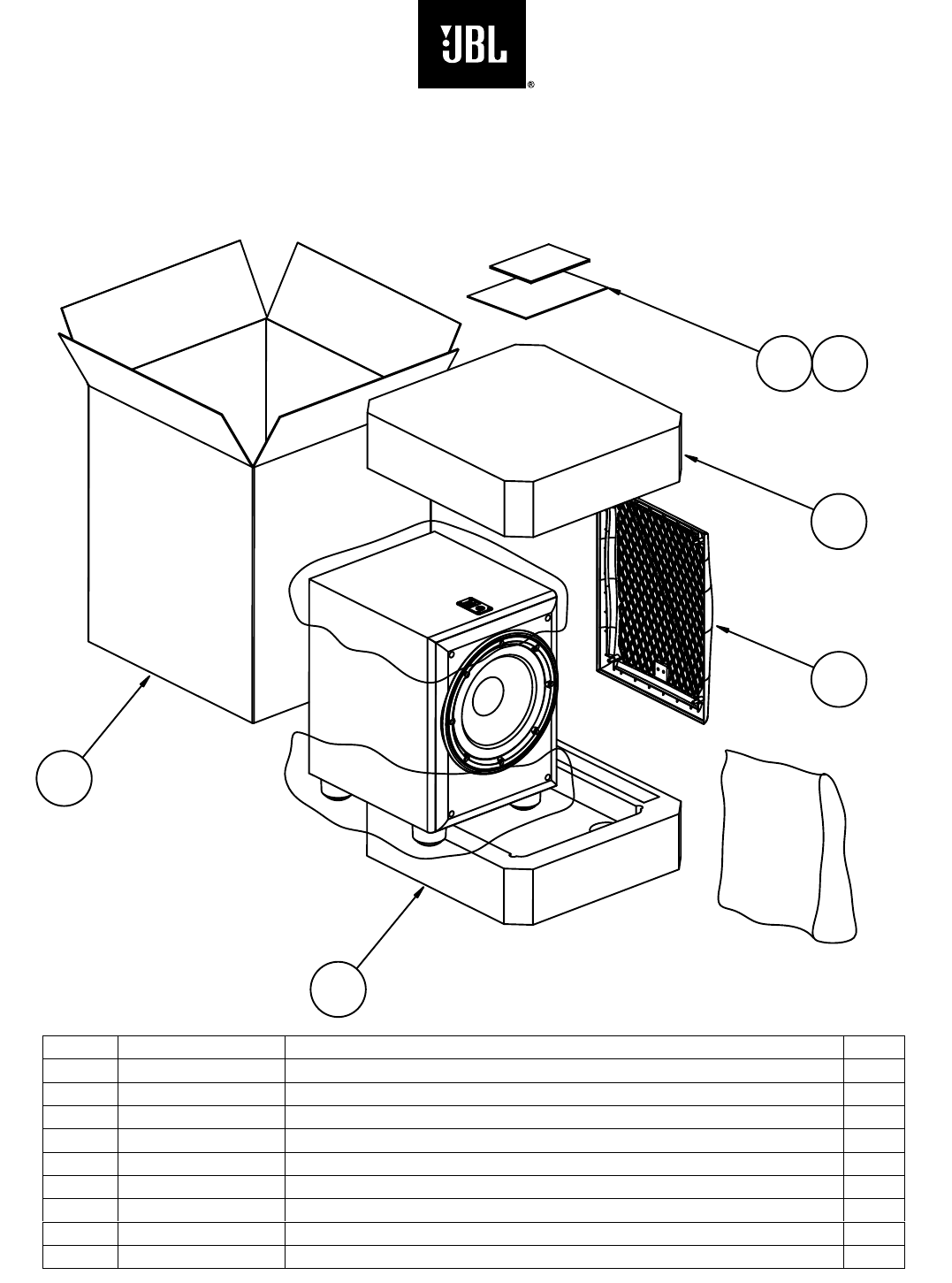
E250P
Packaging
Ref# Part Number Description Qty
1 351249-002 MANUAL, OWNER-E250P/E250P 1
2 351249-001 CARTON,MASTER-E250P (BEECH MODEL) 1
351249-003 CARTON,MASTER-E250P (BLACK MODEL) 1
350884-003 CARTON,MASTER-E250P (CHERRY MODEL) 1
3 351252-001 PAD,END,TOP-E250P 1
4 351252-002 PAD,END,BOT-E250P 1
5 338381-001 WARRANTY CARD,1/5YR,JBL 1
14 352024-001 ASY, GRILLE, BLK, FRNT 1
3
1 5
3
2
4
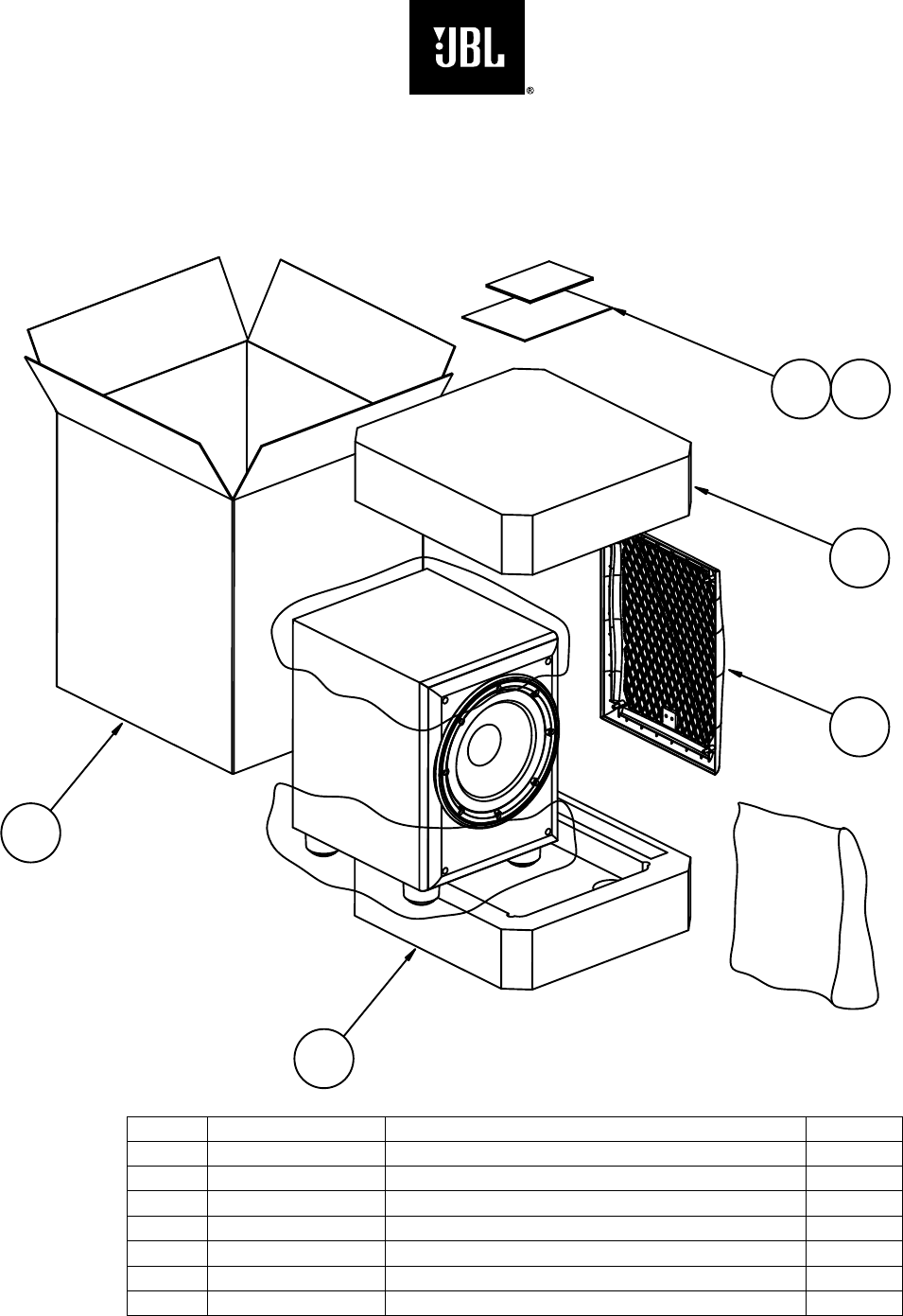
Packaging
P12SW
6
Ref# Part Number Description Qty
1 361803-001 P12SW Owner’s Manual 1
2 361813-001 P12SW Outer Carton 1
3 351252-001 Packing Foam (Top) 1
4 351252-002 Packing Foam (Bottom) 1
5 338381-001 Warranty Card 1
6 352024-003 Front Grille 1
4
JBL E250P/P12SW Powered Sub/ Plate Amp
LINE VOLTAGE Yes/No Hi/Lo Line Nom. Unit Notes
US 120vac/60Hz Yes 108-132 120 Vrms Normal Operation
EU 230vac/50-60Hz Yes 207-264 230 Vrms Normal operation, MOMS required
Parameter Specification Unit QA Test
Limits Conditions Notes
Amp Section
Type (Class AB, D, other) D n/a n/a
Load Impedance (speaker) 5.6 Ohms n/a Nominal
Rated Output Power (120VA
C
150 Watts 140 Domestic version only 120 VAC-60 Hz
Rated Output Power (230VA
C
150 Watts 130 EU Version only 230 VAC-50 Hz
AVG RMS Dynamic Power 250 Watts 225
Average RMS power, 3/20 Cycles 50 Hz, Driven
6dB above its input sensitivity sensitivity
THD @ Rated Power 0.3 % 122k filter 145 Watts
THD @ 1 Watt 0.1 % 0.5 22k filter
DC Offset 10 mV-DC 30 @ Speaker Outputs
Damping factor >50 DF 35 Measured at amplifier board
Measured at the speaker cable. 150 Watts @
THD < 0.1 % @ 50 Hz
Input Sensitivity
Input Frequency 50 Hz 50 Nominal Freq.
L&R 240 mVrms ±2dB To 150 Watts Single input driven
LFE input 240 mVrms ±2dB To 150 Watts Single input driven, LFE switch ON
Speaker/Hi Level Input 2.4 Vrms ±2dB To 150 Watts Single input driven
Signal to Noise
SNR-A-Weighted 90 dBA 70 relative to rated power A-Weighting filter
SNR-unweighted 85 dBr 70 relative to rated power 22k filter
SNR rel. 1W-unweighted 65 dBr 60 relative to 1W Output 22k filter
Residual Noise Floor 1 mVrms 2
Volume @max, using RMS reading
DMM/VOM (or A/P) BW=20 Khz.
Line level inputs must be terminated using
1KOHM
Residual Noise Floor 1.5 mVrms(max) 2
Volume @max, w/ A/P Swept
Bandpass Measurement (Line
freq.+ harmonics) (BW=20 Khz)
Line level inputs must be terminated using
1KOHM
Input Impedance
Line Input (L, R,LFE) 10K ohms n/a Nominal
Speaker/Hi Level Input > 4.7K ohms n/a Nominal
Filters
LP filter 4th order fixed 60-180 Hz ± 10 2nd order variable + 2nd order fix-24 db/Octave
Subsonic filter (HPF) 3rd Ord
e
Fixed
LFE Low pass 2nd order 200>LP<1K Hz LFE input driven only
HP speaker out connector 200 Hz ± 10
Speaker input driven - Speaker out
loaded with 4 Ohms (Applies only to 230V Model)
Note: 120V Models do not
have speaker output 100 Hz ± 10
Speaker input driven - Speaker out
loaded with 8 Ohms (Applies only to 230V Model)
Limiter
THD at Max. Output Power n/a n/a functional Maximum Output Power Maximum THD as a result of limiting.
Features --
Volume pot Taper (lin/log) LOG -- functional A Taper
Phase switch 0-180 deg functional
LP Filter defeat switch YES functional Disables LP filter, intended for LFE
Input Configuration
Line In (L,R) & LFE YES -- functional Dual RCA jack
Spkr/Hi Level In YES -- functional Binding post connector L&R
Signal Sensing (ATO)
Auto-Turn-On (yes/no) YES functional
ATO Input test frequency 50 Hz functional "
ATO Level LFE Input 4 mV functional " Maximum acceptable level.
ATO Level Speaker in 50 mV functional " Maximum acceptable level.
ATO Turn-on time 5 ms functional
Amp connected and AC on, then
input signal applied
Auto Mute/ Turn-OFF Time 15 minutes 15
T before muting, after signal is
removed
Auto turn of time (T) must be 5 > T < 15
Minutes
Power on Delay time 3 sec. 4AC Power Applied
Transients/Pops
ATO Transient 5 mV-peak n/a @ Speaker Outputs
5
E250P/P12SW subwoofers
Parameter Specification Unit QA Test
Limits Conditions Notes
Turn-on Transient 50 mV-peak 2v-pp @ Speaker Outputs AC Line cycled from OFF to ON
Turn-off Transient 50 mV-peak 2v-pp @ Speaker Outputs AC Line cycled from ON to OFF
Efficiency
Efficiency 65 % 64 Nominal Line voltage 120 VAC
Stand-by Input Power 24 Watts 26 @ nom. line voltage
Maximum allowable input power under nominal
Input voltage and frequency, HOT or COLD
operation.
Power Cons. @ rated power 234 Watts 240 @ nom. line voltage 150 Watts @ 5.6 Ohms nominal line voltage
Protections
Short Circuit Protection YES functional Direct short at output
Amplifier should resume operation after short
circuit condition removal
Thermal Protection YES functional
@1/8 max unclipped Power at 1.06
times the input voltage
Temperature rise in accessible metal parts
should not exceed 35K rise for domestic version
or 30K rise for European versions (refer to
requirements sheet).
DC Offset Protection YES -DC present at Speaker Out leads
Design must insure no Offset at the speaker
output under any operating condition including
abnormal operation
Line Fuse Rating
USA-Domestic 2 Amps 2Type-T or Slo Blo-250 V Internal fuse with UL/SEMKO rated holder
EU 1.25 Amps 1.25
Type-T or Slo Blo-250 V, Low
Breaking capacity Internal fuse with UL/SEMKO rated holder
4. ALL SPECS SHOULD BE MEASURED AT NOMINAL LINE VOLTAGE.
SPEAKER CONNECTION
When we designed the E150P, E250P, P10SW and P12SW powered subwoofers, our
goal was to offer the user the best possible performance combined with the most flexible
and complete installation options.
Please look over the following three examples to determine which description best
matches your system and follow the corresponding hookup instructions.
To use the binding-post speaker terminals with bare wire, unscrew the collar until the
hole through the center post is visible under the collar. Insert the bare end of the wire
through the hole in the post, then screw the collar back down until the connection is
tight. The holes in the center of the collars are intended for banana-type connectors.
Speakers and electronics terminals have corresponding positive (+) and negative (–)
terminals. It is important to connect both speakers identically: positive (+) on the speaker
to positive (+) on the amplifier and negative (–) on the speaker to negative (–) on the
amplifier. Wiring “out of phase” results in thin sound, weak bass and a poor stereo image.
NOTE: The speaker-level connection method described on the next page is not a
preferred connection and should only be resorted to if your receiver/processor does not
have a line-level or subwoofer output. The customer is responsible for proper
connections, and any damage to JBL or other equipment due to improper connections
will not be covered by your JBL warranty. Consult with your JBL dealer or an audio
installation expert if you have any questions about how to connect your subwoofer using
the speaker-level inputs.
6
E250P/P12SW subwoofers
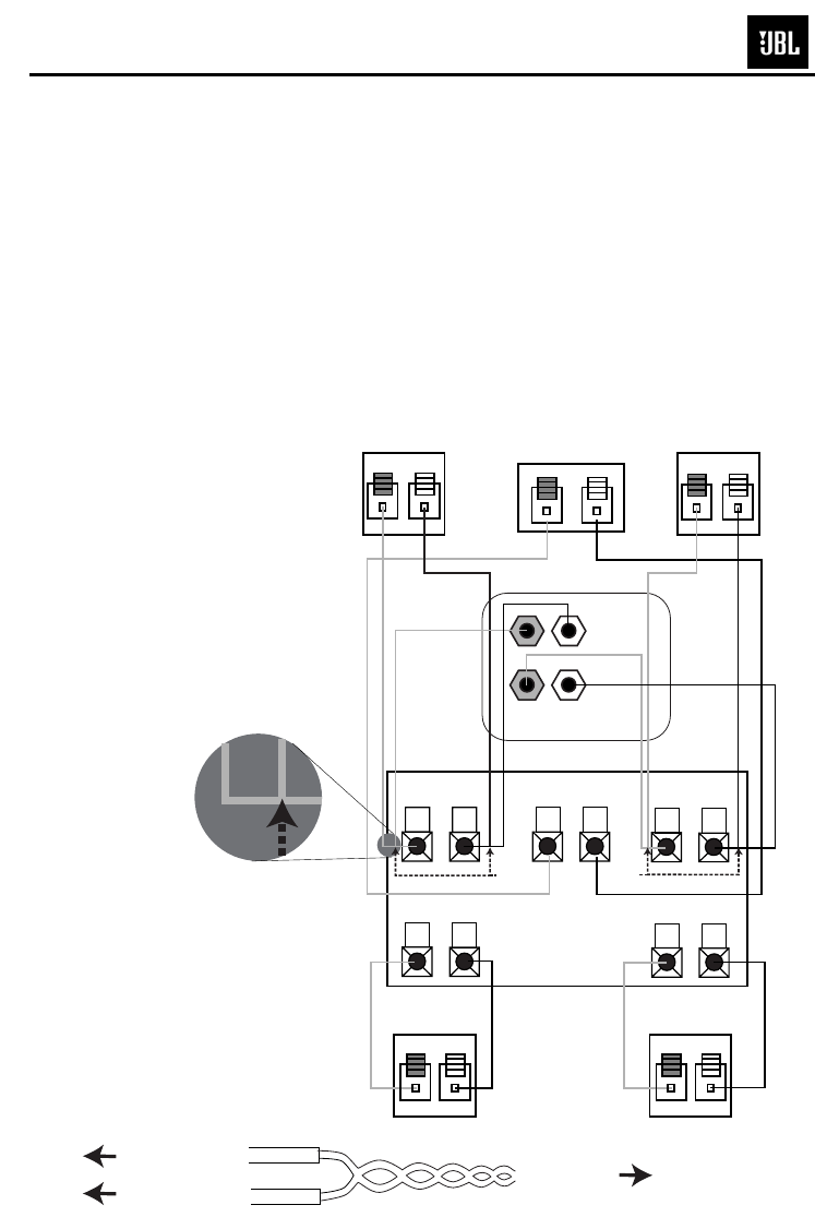
Analog Receiver/Processor – Speaker-Level Connections
Use this installation method
only with an analog receiver/
processor that does not have
digital processing or bass
management, and also does
not have a subwoofer output
or a volume-controlled preamp
(line-) level output:
Connect the speaker wires for
both your main left and right
speakers, and for the sub-
woofer, to the same speaker
terminals on your receiver or
amplifier. The wires may be
joined by twisting together the
bare ends of the two leads
that will be connected to each
terminal on the receiver/
amplifier, as shown in the
diagram. This procedure
should be done only four times
(involving a total of eight bare-
wire ends), and only for those
wire ends that are being con-
nected to the terminals on
your receiver/amplifier. It is
important that you avoid join-
ing any other wires. Do not
twist together
wire ends that
are being
inserted into
terminals on any
speaker or on the
subwoofer. Do not twist
together wire ends that will be
used for any speakers other
than the front left and right
speakers or the subwoofer.
Refer to the connection dia-
gram for guidance.
Twist together the (+) leads at
one end of the speaker wires
that you have designated for
the left front speaker and for
the left high-level inputs on
the subwoofer. Insert the
joined (twisted) wires into the
left front (+) terminal on your
receiver/amplifier. Connect the
free end of the (+) lead for the
left front speaker to the (+) ter-
minal on the back of the
speaker. Connect the free end
of the (+) lead for the left input
on the subwoofer to the left
binding-post terminal. Repeat
this process for the (–)
connections for the left front
speaker and left input on the
subwoofer, and then for the (+)
and (–) connections for the
right front speaker and right
high-level inputs on the sub-
woofer.
Connect your receiver or
amplifier’s center and sur-
round speaker terminals to the
corresponding terminals on
the back of your center and
surround speakers.
Right Front
Left Front Center + –
+ – + –
Subwoofer
Right SurroundLeft Surround
+ – + –
+ –
+ –
Left Front Center
+ –
Left Surround
Right Front
+ –
Right Surround
+ –
Receiver
L
R
HIGH
LEVEL
IN
L
R
+ –
Twist
Here Twist
Here
To (+) terminal on
left speaker
To (+) terminal of left
input on subwoofer
To front left
(+) terminal on
receiver/amplifier
7
E250P/P12SW subwoofers
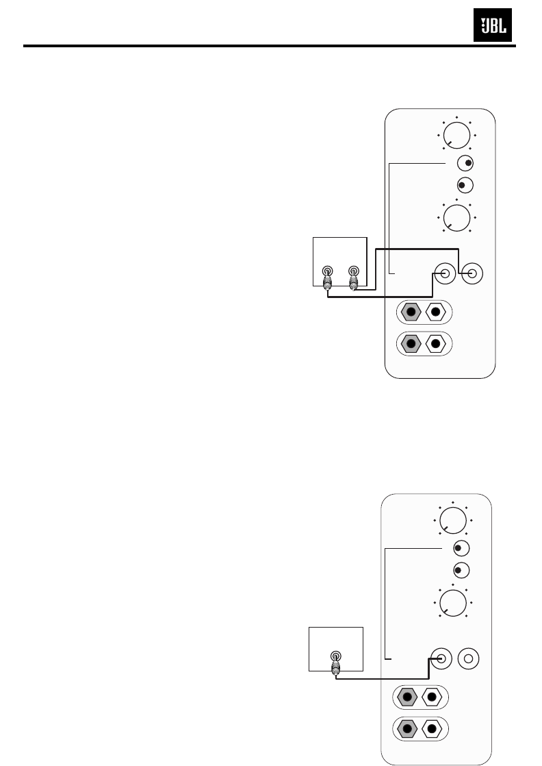
Digital Receiver/Processor – LFE Connection
Use this installation method
for Dolby Digital, DTS®or other
digital surround processors
that have bass-management
programming, or for analog
receivers/processors that
have a filtered subwoofer
output:
IMPORTANT:Make sure that
the LFE toggle switch on the
subwoofer is in the “LFE”
position. Use the line-level
input jacks for the Low-
Frequency Effects channel.
Connect these jacks to the LFE
output or subwoofer output on
your receiver or amplifier.
Note: If your receiver or ampli-
fier has only one subwoofer
output jack, you may connect
the subwoofer output on your
receiver/preamplifier to either
the left or right line-level input
on the subwoofer. It makes no
difference which jack you
choose.
Connect each speaker to
the corresponding speaker
terminals on your receiver or
amplifier.
Make sure that you have
configured your surround
sound processor for
“Subwoofer On” or
“LFE On.” The front,
center and surround
speakers should be
set to “Small” or “Large”
depending on their size and
frequency response. Consult
your receiver’s or processor’s
owner’s manual.
CROSSOVER
FREQUENCY
LEVEL
LINE LEVEL IN
PHASE
Min Max
L R
LFE NORMAL
HIGH
LEVEL
IN
+ –
50Hz
0º 180º
150Hz
Subwoofer
Output/LFE
RECEIVER/PREAMPLIFIER
L
R
For LFE use L or R
Analog Receiver/Processor – Line-Level Connections
Use this installation method
with an analog receiver/
processor that does not have
digital processing or bass
management, and that is
equipped with a full-range
subwoofer output or a volume-
controlled preamp (line-) level
output:
Use RCA-type interconnect
cables to connect the line-
level subwoofer outputs on
your receiver or amplifier to
the line-level inputs on the
subwoofer.
IMPORTANT: Make sure that
the LFE toggle switch on the
subwoofer is in the “Normal”
position. Do not use the
“LFE” position with Dolby*
Pro Logic*-only processors.
Note: If your receiver or
amplifier has only one sub-
woofer output jack, then you
may connect the subwoofer
output on your receiver/pre-
amplifier to either the left or
right line-level input on the
subwoofer. It makes no differ-
ence which jack you choose.
Connect each speaker to
the corresponding speaker
terminals on your
receiver or amplifier.
Make sure your receiver
or processor is config-
ured so
that the sub-
woofer is “On.”
Note for advanced
users: If your receiver/
processor has a built-in low-
pass crossover filter for the
subwoofer output, then the LFE
switch should be set to the
“LFE” position to bypass the
subwoofer’s internal
crossover.
CROSSOVER
FREQUENCY
LEVEL
LINE LEVEL IN
PHASE
Min Max
L R
LFE NORMAL
HIGH
LEVEL
IN
+ –
50Hz
0º 180º
150Hz
Subwoofer
Out
RECEIVER
L
R
For LFE use L or R
L R
8
E250P/P12SW subwoofers
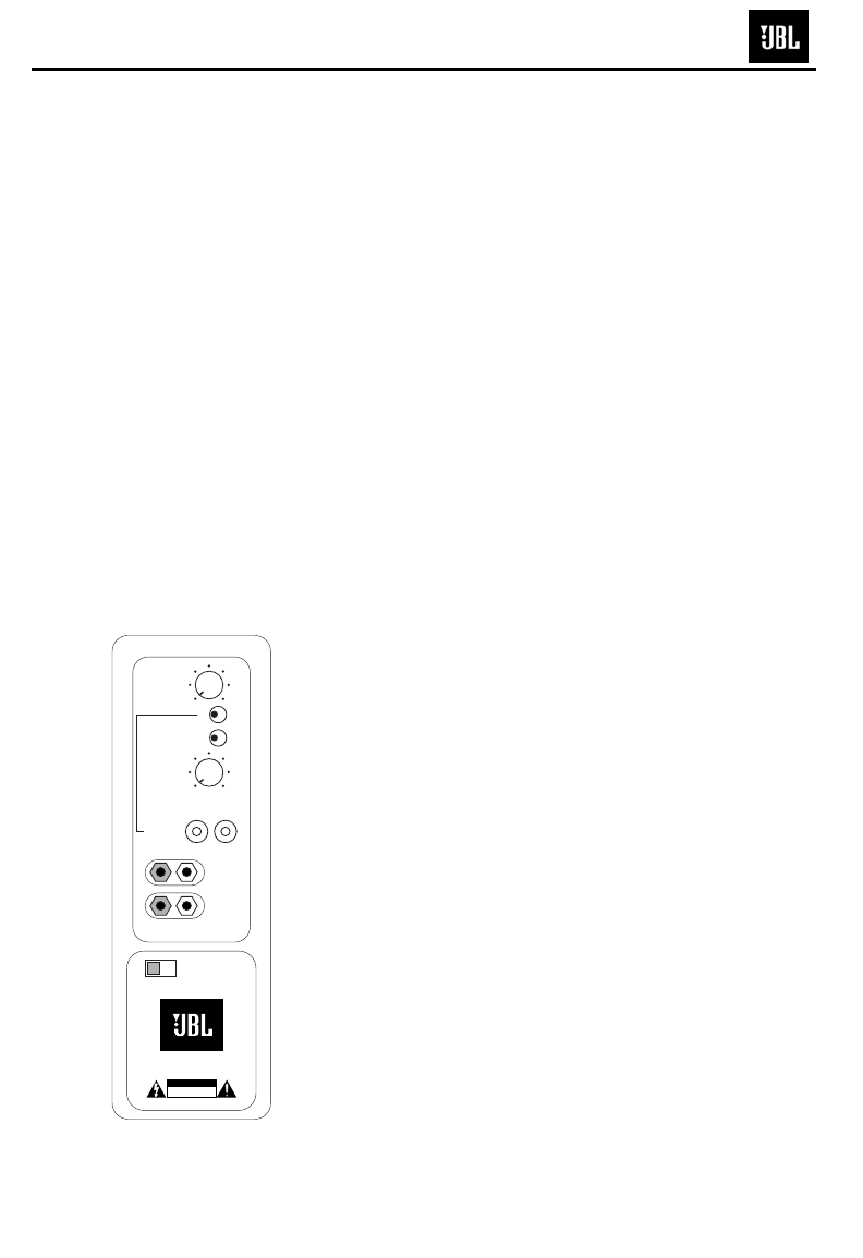
OPERATION
When the unit is plugged in
and the power switch is on
and no signal is received, the
LED on the top of the unit will
turn red. When a signal is
present, the LED will turn
green.
Note: It will take several min-
utes for the LED to turn from
green to red after the input
signal to the subwoofer is
removed. Due to JBL’s unique
high-output,
high-efficiency
amplifier design, power con-
sumption is minimal when the
subwoofer is not receiving a
signal. Of course, the sub-
woofer can be turned off,
whenever desired, if you do
not wish to leave it in auto
(standby) mode.
The subwoofer Level Control
adjusts the volume of the
subwoofer relative to the rest
of the system. Proper level
adjustment depends on sev-
eral variables such as room
size, subwoofer placement,
type of main speakers and
position. Adjust the subwoofer
level so that the volume of the
bass information is pleasing
to you.
Crossover Adjustments
The Crossover Frequency
Control determines the highest
frequency at
which the sub-
woofer reproduces
sounds. If
your main speakers can com-
fortably reproduce some low-
frequency sounds, set this
control to a lower frequency
setting, between 50Hz and
100Hz. This will concentrate
the subwoofer’s efforts on the
ultradeep bass sounds
required by today’s films and
music. If you are using smaller
bookshelf speakers that do not
extend to the lower bass fre-
quencies, set the low-pass
crossover control to a higher
setting, between 120Hz and
150Hz. This control is not used
when the LFE switch is in the
“LFE” position.
Level Control
Power
CROSSOVER
FREQUENCY
LEVEL
LINE LEVEL IN
PHASE
Min Max
L
R
L R
For LFE use L or R
LFE NORMAL
Northridge E Series
HIGH
LEVEL
IN
POWER
+ –
120V
60Hz
50Hz
0º 180º
150Hz
CAUTION
RISK OF ELECTRIC SHOCK
DO NOT OPEN
ON OFF
* E250P: LED is on the amplifier faceplate
*
9
E250P/P12SW subwoofers

TROUBLESHOOTING
If you used the high-level
(speaker) inputs and there
is no sound from any of the
speakers:
•
Check that the receiver/
amplifier
is on and a source
is playing.
• Check that the powered
subwoofer is plugged into
an active electrical outlet
and is switched on.
• Check all wires and connec-
tions between the receiver/
amplifier and the speakers.
Make sure all wires are con-
nected. Make sure none of
the speaker wires are frayed,
cut or punctured, or touching
each other, except for the
wires for the front left and
right speakers, which may be
joined with the wires for the
subwoofer at the receiver/
amplifier end only, if you are
using the speaker-level
connections as described
on page 4.
• Review proper operation
of your receiver/amplifier.
If there is low (or no) bass
output:
• Make sure the connections
to the left and right “Speaker
Inputs” have the correct
polarity (+ and –).
• Make sure that the sub-
woofer is plugged into an
active electrical outlet and
switched on.
• Adjust the crossover point.
• Flip the Phase Control switch
to the opposite position.
• If you are using a Dolby
Digital/DTS receiver or
processor, make sure that the
subwoofer adjustments on
the receiver/processor are
set up correctly.
• Slowly turn the Level Control
clockwise until you begin to
hear the desired amount of
bass.
If you used the line-level
inputs and there is no sound
from the subwoofer:
•
Check that the receiver/
amplifier
is on and a source is
playing.
• Check that the powered
subwoofer is plugged into an
active electrical outlet and is
switched on.
• Check all wires and
connections between the
receiver/amplifier and the
subwoofer. Make sure all
wires are connected. Make
sure none of the wires are
frayed, cut or punctured, or
touching each other.
• Review proper operation of
your receiver/amplifier.
• Slowly turn the Level
Control clockwise until you
begin to hear the desired
amount of bass.
• Make sure that you have
configured your receiver/
processor so that the sub-
woofer/LFE output is on.
Phase Control
The Phase Control determines
whether the subwoofer’s pis-
ton-like action moves in and
out in phase with the main
speakers or opposite the
main speakers. There is no
correct or incorrect setting.
Proper phase adjustment
depends on several variables
such as subwoofer placement
and listener position. Adjust
the phase switch to maximize
bass output at the listening
position.
Remember, every system,
room and listener is different.
There are no right or wrong
settings; this switch offers the
added flexibility to adjust your
subwoofer for optimum per-
formance for your specific
listening conditions without
having to move your speakers.
If at some time in the future
you happen to rearrange your
listening room and move your
speakers, you should experi-
ment with the phase switch in
both positions, and leave it in
the position that maximizes
bass performance.
10
E250P/P12SW subwoofers
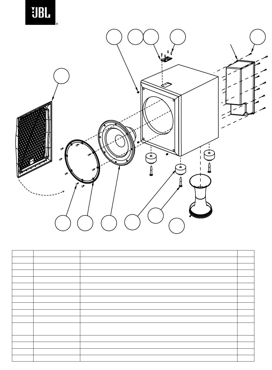
Ref# Part Number Description Qty
6 351348-001 PLATE,LED/LOGO-E250P 1
7 338125-002 ASY,LED-E250P/E250P 1
8 336486-001 ASY,FOOT,PLSTC- E250P 4
9 763-31110-40 SCREW, 8 X 2 1/2,TR,PH,PB,BLK ZINC,LCS (FOOT) 4
10 908302-012 SCREW, PB,HXS,#6x.75,ZINC (LOGO PLATE) 4
11 903802-016 SCREW, PB,HXS,#8x1",ZINC (WOOFER) 8
12 338128-002
ASY, WOOFER,12" DCR 4.8 Ω 1
13 336799-001 ASY, PORT TUBE 1
14 351307-001 GRILLE, BLK, FRNT 1
15 333249-003 CUP,GRILLE,TITANIUM, (BEECH MODEL) (CHERRY
MODEL) 4
333249-001 CUP,GRILLE (BLACK MODEL) 4
16 351243-001 RING,TRIM,12"-E250P 1
17 903401-012 SCREW, 6 X 3/4,PAN,PH,PB,BLK ZINC,LCS (AMPLIFIER) 10
13
12
16
15 7
610 17
14
11
9
8
Amplifier – Not for Sale
E250P
Exploded View
11
9
8
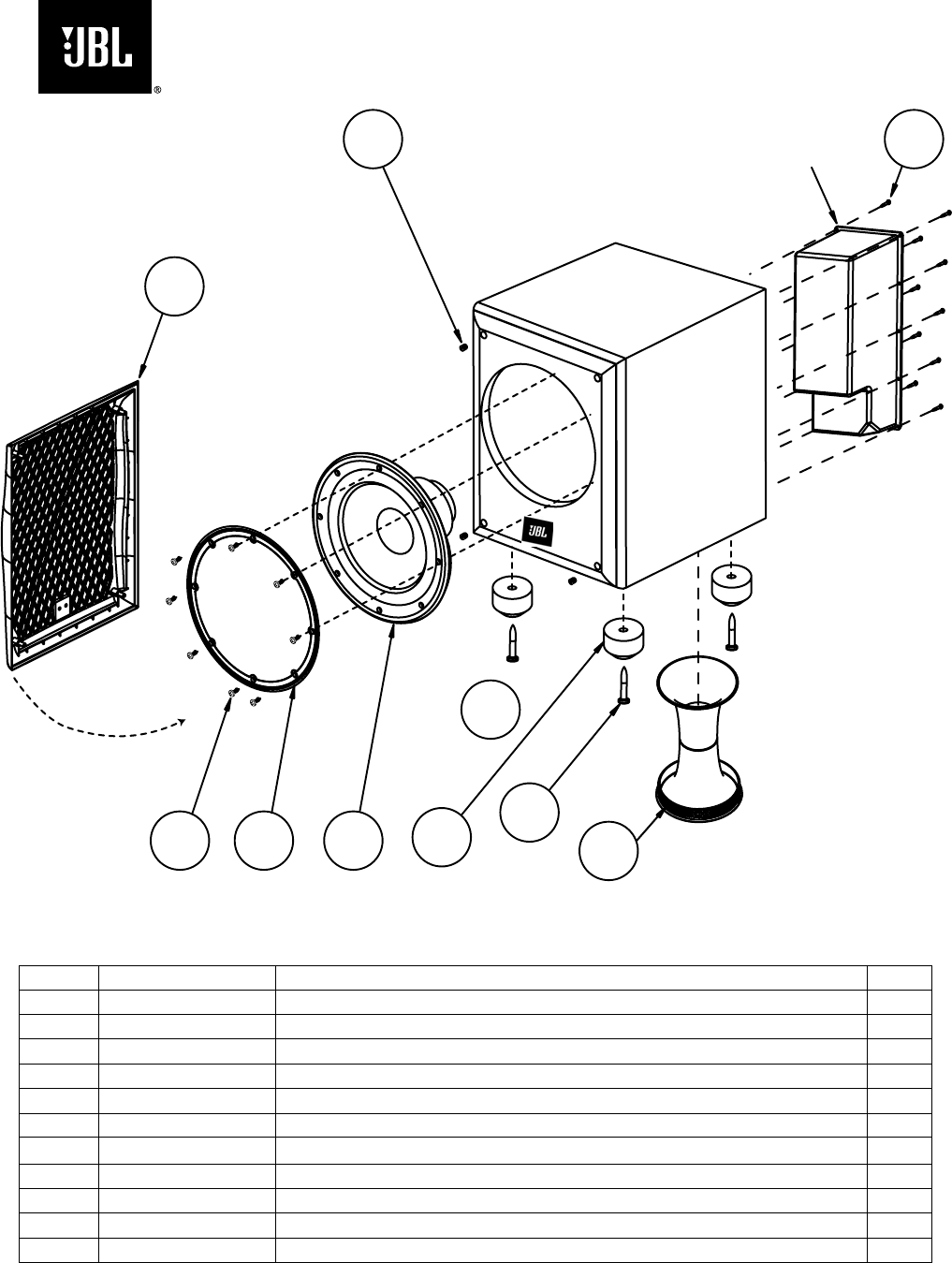
Amplifier – Not for Sale
Exploded View
P12SW
Ref# Part Number Description Qty
1 352024-003 ASY, GRILLE, BLK, FRNT 1
2 333249-001 CUP,GRILLE 4
3 882-41110-12 SCREW, 6 X 3/4,PAN,PH,PB,BLK ZINC,LCS (AMPLIFIER) 10
4 903802-016 SCREW, PB,HXS,#8x1",ZINC (WOOFER) 8
5 351243-001 RING,TRIM,12" 1
6 338128-002
ASY, WOOFER,12" DCR 4.8 Ω 1
7 336799-001 ASY, PORT TUBE 1
8 336486-001 ASY,FOOT,PLSTC 4
9 883-31110-40 SCREW, 8 X 2 1/2,TR,PH,PB,BLK ZINC,LCS (FOOT) 4
10 361872-001 JBL LOGO 1
1
23
4567
10
12
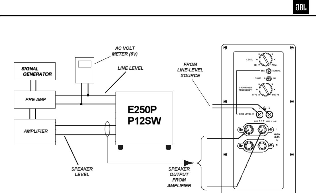
TEST SET-UP AND PROCEDURE
General Function
UUT = Unit Under Test
1) Connect a pair of level input cables (RCA) from signal generator to either Right or Left Level input on UUT. LEVEL
control should be full counterclockwise (MIN). Make sure the LFE/Normal switch is in the NORMAL position.
2) Turn on generator, adjust to 100mV, 50Hz.
3) Plug in UUT; Turn Main Power switch ON. LED may be either Red or Green. Turn LEVEL control full clockwise
(MAX). Low Pass control should be set fully clockwise (150Hz).
4) LED should turn Green; immediately bass response should be heard and felt from port tube opening.
5) Turn off generator, turn LEVEL control fully counterclockwise (MIN), disconnect RCA cables.
6) Connect one pair of speaker cables to either high level input terminal on UUT. Cables should be connected to an
integrated amplifier fed by the signal generator.
7) Turn on generator and adjust so that speaker level output is 1.0V, 50Hz. Turn LEVEL control full clockwise (MAX).
8) Green LED should light, immediate bass response should be heard and felt from the port tube opening.
Sweep Function
1) Follow steps 1-4 above, using a sweep generator as a signal source.
2) Sweep generator from 20Hz to 300Hz. Listen to the cabinet and drivers for any rattles, clicks, buzzes or any other
noises. If any unusual noises are heard, remove driver and test.
Driver Function
1) Remove driver from cabinet; detach + and - wire clips.
2) Check DC resistance of driver; it should be 4.8 ohms.
3) Connect a pair of speaker cables to driver terminals. Cables should be connected to an integrated amplifier fed by a
signal generator and adjust so that speaker level output is 5.0V.
4) Sweep generator from 20Hz to 1kHz. Listen to driver for any rubbing, buzzing, or other unusual noises.
13
E250P/P12SW subwoofers
& P10SW
& P12SW
14
E250P/P12SW subwoofers
JBL Incorporated 250 Crossways Park Dr. Woodbury, New York 11797 (516) 496-3400
Service Bulletin
Service bulletin # JBL2005-01 December 2005 Warranty labor rate: MINOR repair
To: All JBL Service Centers
Model: E150P, E250P Subwoofers
Subject: “Chirp” Noise on Power-Up
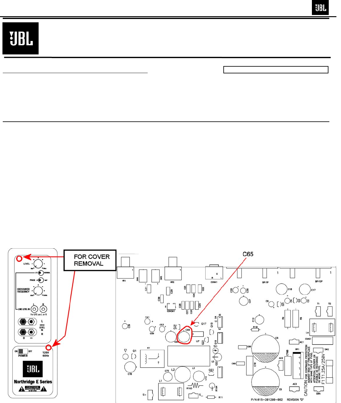
In the event you receive an E150P or E250P with the complaint: “the subwoofer make a slight “chirp”
noise when it becomes active from the stand-by mode”, perform the following modification.
Synopsis: Change C65 PE capacitor from 470µf to 47µf.
1) Remove the amplifer from the enclosure.
2) Remove the cover.
3) Change C65 Electrolytic capacitor from 470µf,16V to 47µf,16V, JBL part# 034-470515-200. Observe
polarity.
4) Replace cover, replace amplifier in enclosure, test subwoofer.
15
E250P subwoofer

TECH TIPS
Troubleshooting tips and solutions to common service problems
For models: E150P,E250P TIP# JBLTT2003-04 Rev2
P10SW, P12SW
PB10,PB12 (Revision 2) *
Subject: Replacing MOSFETS Q18, Q22
In the event you need to replace MOSFET transistors Q18 or Q22 as part of a repair, it is
important to use ONLY:
• JBL part# 051-640001-000
• Or JBL part# FE106401110
• Or only the brands: International Rectifier, or Fairchild.
Replace both Q18 and Q22 MOSFET’s in the circuit, even if only one seems to be damaged.
Do NOT mix & match these components from different manufacturers, or batches. They should be
identical.
* Late version PB10 or PB12 subwoofers (Revision 2 in the service manual) can be identified by:
• Amplifier serial number starts with “HA”
• Output transistors in the open, on a large black heatsink
• Large plastic cup enclosing the rear of the amp assembly
• Main PCB, bottom, solder-side contains all SMD devices
16
E250P/P12SW subwoofers
A. Power Amp Section
Resistance
Check Resistance from S+ (SPK O/P) to GND should be >1M Ω (NO LOAD)
Resistance from V+ (C6 P+) to V- (C8 P-) gradually Fully CHARGED should read >10k Ω
Resistance from V+ (C6 P+) to S+ (SPK O/P) should read >1MΩ
Resistance from V- (C8 P-) to S+ (SPK O/P) should read >1M Ω
2. Power Up LED RED
With a 5mV signal to Low level input, LED should change to GREEN
-Voltage measurements (DVM)
OP AMP
LED P-U4(1) P-U4(7)
RED 0Vrms 11.84VDC
GREEN 7.13Vrms -12.93VDC
3. D.C. Operation
-Voltage measurements (DVM) on CLASS D POWER AMP
Between V+ Q4(E) Q1(C) Q10(C) U7(1) U7(2) U7(4) U7(6) U7(7) U7(8)
And This
Point GND V- GND GND GND GND GND GND GND GND
Get this
Reading 71.7V 0V -71.7V 0V -71.7V -71.5V -71.2V 0V 0V 4.65V
4. Check Switching Frequency
• Oscilloscope - USE THE PROBE TIP TO U6(7) TO GND
• Reading 100kHz +/-10%,24Vp-p
B. Pre Amp Section
Line Level Input Sensitivity
-Set up Turn level, X’OVER FREQ POT Fully CW and LFE switch off
Generator Set at 200mV@50Hz
Signal to Line level input
DETAILED TROUBLESHOOTING
17
E250P/P12SW subwoofers
- Voltage measurements
OP AMP
U2(1) U2(14) U2(8) U3(7) U3(1) U3(14) U3(8) U5(7) U5(1)
SPEAKER
O/P
306.9mV 461mV 460mV 658mV 628mV 598mV 2.326V 2.02V 3.57V 23.33V
2. High Level Input Sensitivity
-Set up Turn level, X’OVER FREQ POT Fully CW and LFE switch off
Set Generator at 1.3V@50Hz
Signal to High level input
-Voltage measurements 15.3V at speaker output
3. Low-Pass
-Set up Set Generator at 200 mV@100Hz
Signal to Line level input
Measure voltage at S+ speaker output
-Voltage measurement
X’OVER FREQ. Setting Output
CW 14.03V
CCW 4.8V
4. LFE
-Set up Set Generator at 200mV@200Hz
Signal to Line level input
Measure voltage at S+ speaker output
LFE switch Setting Output
Normal 6V
LFE 18.32V
See flow chart next page for diagnostics.
DETAILED TROUBLESHOOTING (CONT'D)
18
E250P/P12SW subwoofers
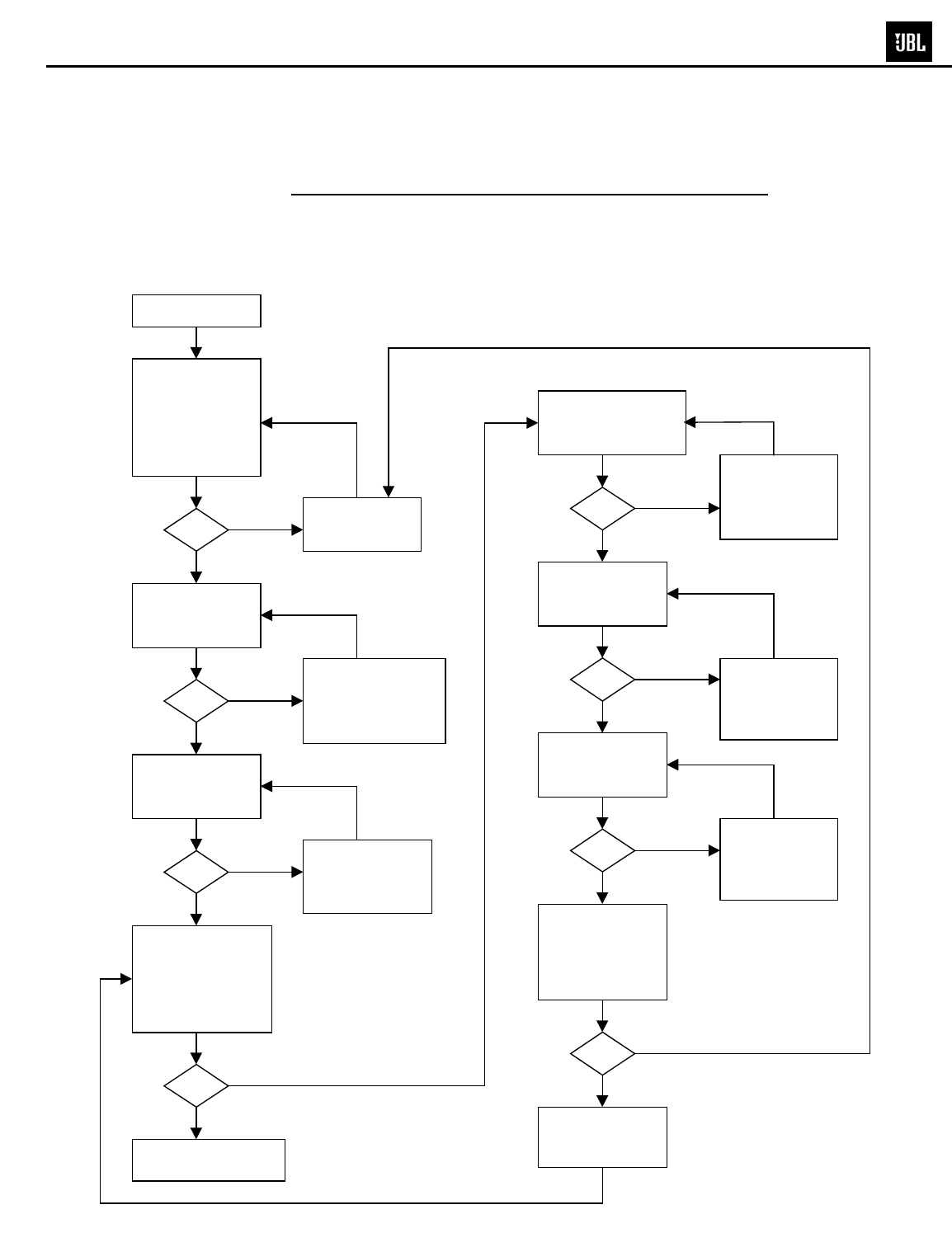
CAUTION : SPEAKER OUTPUT IS FLOATING AND IS NOT PROTECTED AGAINST A SHORT
TO GROUND. ALL TEST INSTRUMENTS CONNECTED TO THE OUTPUT MUST
BE FLOATING. ATTACH THE SCOPE PROBE TIP TO S - and REFERENCE
LEAD TO S+.
(A 10mV signal may need from the input to trigger the Switch turn on)
no
no
yes
yes
no
no
yes
yes
no
no
yes
yes
no
no
yes
yes
START
Check +/-15V-MOD
+/-15V voltage at
U 6(8),U6(4)
Discharge C37,
Check fuse
transformer, L4,
rectifier, C6 and C8
Use scope to check
switching
frequency U6(7)
100KHz
+/-10% , ~24Vp-p
Check Q4(E)
TO V-
= 0V D.C.
Power up with no
signal input
LED RED
OK
OK
OK
OK
OK
OK
OK
OK
Check
MUTE(+8V) and
Q24,Q25,Q26
Use scope to
check O/P U7(6)
and GND
143Vp-p square
wave shown
Check
L2,L3,C71,C72,
C73
,
C74
I/P:10mv/50HZ
Check +15V/SW
Q4(E) TO V-
15V
Replace
Q18,Q22
CLASS D AMP OK
END
Check
U7,Q16,Q17,
Q20,Q21,R87,
D26,D35,C64
Check
FB1,FB2,C45,
C50,C60,C63,
R81,R82
Check
U7(1) = -58.3V
Check
MUTE(-12.9V),
And
Q24,Q25,Q26
Resistance check
(no load)
between V+ V-,
V+ O/P,V- O/P
and O/P to GND
is > 10K
DETAILED TROUBLESHOOTING (CONT'D)
FLOW CHART
19
E250P/P12SW subwoofers
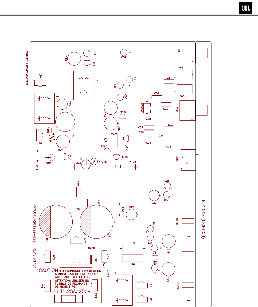
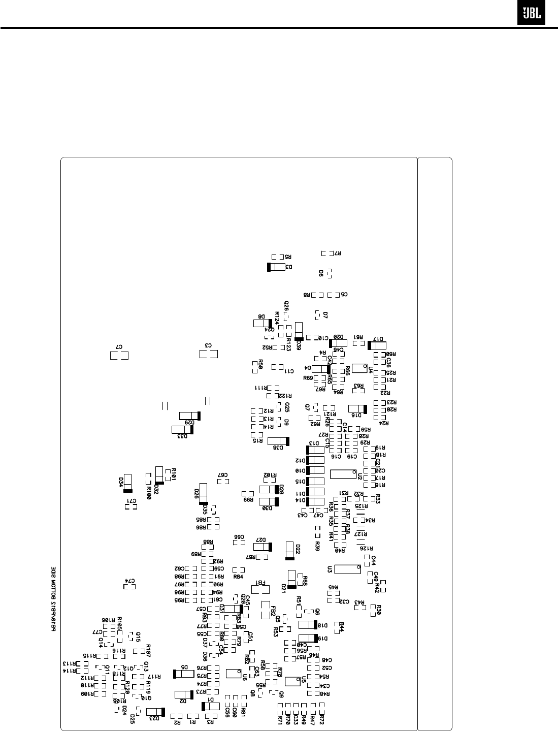
20
E250P/P12SW subwoofers
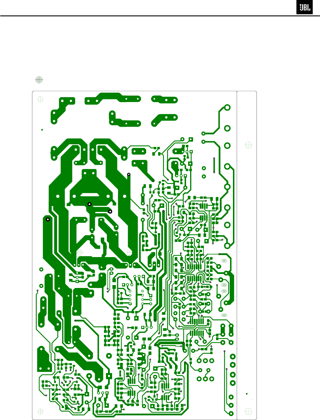
21
E250P/P12SW subwoofers
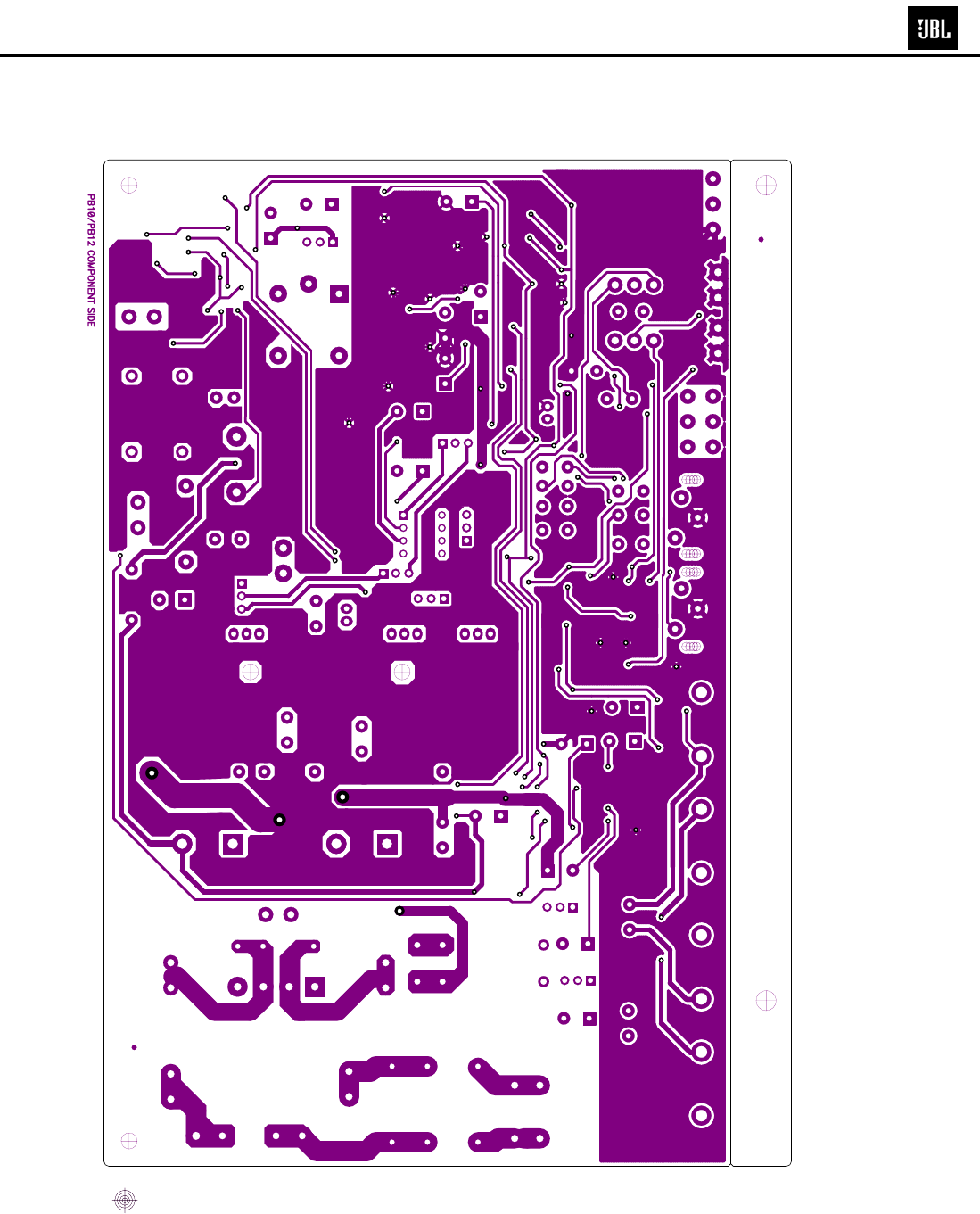
22
E250P/P12SW subwoofers
23
E250P/P12SW subwoofers

E250P/P12SW (120v) Electrical Parts List
Part Number Description Reference Designator Qty
Resistors
020-220497-120 Carbon Film 2K2 1/4W J R11 1
021-100401-120 MOF Resistor 1K 1W J R103 1
021-120403-020 MOF Resistor 1K2 3WS J 8x20 R9 1
021-120405-020 MOF Resistor 1K2 5WS J 8x25 R6 1
021-220202-120 MOF Resistor 22R 2W(S) J MB TYPE 15x8 R10 1
022-500003-020 KNP Resistor 0R05 3WS J FK TYPE R104 1
024-000098-120 SMD Resistor 0R 1/8W J 0805 R125,126 2
024-100298-120 SMD Resistor 10R 1/8W J 0805 R81,82 2
024-100398-120 SMD Resistor 100R 1/8W J 0805 R62 1
024-100498-120 SMD Resistor 1K 1/8W J 0805 R79,83,92,95,96,105,108,127,65 9
024-100598-120 SMD Resistor 10K 1/8W J 0805 R2,17,19,37,54,58,63,71, 8
024-100698-120 SMD Resistor 100K 1/8W J 0805 R3,112,22-25 6
024-110598-100 SMD Resistor 11K 1/8W F 0805 R98 1
024-120698-120 SMD Resistor 120K 1/8W J 0805 R39 1
024-121598-100 SMD Resistor 12K1 1/8W F 0805 R38 1
024-137698-100 SMD Resistor 137K 1/8W F 0805 R32 1
024-150498-120 SMD Resistor 1K5 1/8W J 0805 R67,68 2
024-180598-120 SMD Resistor 18K 1/8W J 0805 R29 1
024-187698-100 SMD Resistor 187K 1/8W F 0805 R45 1
024-200598-120 SMD Resistor 20K 1/8W J 0805 R94 1
024-220398-120 SMD Resistor 220R 1/8W J 0805 R90 1
024-220498-121 SMD Resistor 2K2 1/8W J 0805 R1,87,61 3
024-220598-120 SMD Resistor 22K 1/8W J 0805 R118 1
024-220798-120 SMD Resistor 2M2 1/8W J 0805 R80,121 2
024-237598-120 SMD Resistor 23K7 1/8W F 0805 R48 1
024-243698-100 SMD Resistor 243K 1/8W F 0805 R36 1
024-270498-120 SMD Resistor 2K7 1/8W J 0805 R73,64 2
024-300398-120 SMD Resistor 300R 1/8W J 0805 R55 1
024-300598-120 SMD Resistor 30K 1/8W J 0805 R56 1
024-330498-120 SMD Resistor 3K3 1/8W J 0805 R7,8,12-15,59 7
024-330598-120 SMD Resistor 33K 1/8W J 0805 R4,5 2
024-332498-100 SMD Resistor 3K32 1/8W F 0805 R26,27, 2
024-360498-120 SMD Resistor 3K6 1/8W J 0805 R28 1
024-390498-120 SMD Resistor 3K9 1/8W J 0805 R93 1
024-390598-120 SMD Resistor 39K 1/8W J 0805 R77 1
024-430498-100 SMD Resistor 4K3 1/8W F 0805 R78 1
024-453598-100 SMD Resistor 45K3 1/8W F 0805 R30 1
024-470298-120 SMD Resistor 47R 1/8W J 0805 R101,102 2
024-470398-120 SMD Resistor 470R 1/8W J 0805 R76,99,100 3
024-470498-120 SMD Resistor 4K7 1/8W J 0805 R85,86 2
024-470598-120 SMD Resistor 47K 1/8W J 0805 R44,47,49,107 4
24
E250P/P12SW subwoofers

Part Number Description Reference Designator Qty
024-470698-120 SMD Resistor 470K 1/8W J 0805 R70 1
024-470798-120 SMD Resistor 4M7 1/8W J 0805 R60 1
024-487498-100 SMD Resistor 4K87 1/8W F 0805 R51,53 2
024-510398-120 SMD Resistor 510R 1/8W J 0805 R57 1
024-560598-120 SMD Resistor 56K 1/8W J 0805 R122 1
024-620398-100 SMD Resistor 620R 1/8W F 0805 R16,18 2
024-680498-120 SMD Resistor 6K8 1/8W J 0805 R46,91,40,41,43,42 6
024-680598-120 SMD Resistor 68K 1/8W J 0805 R33,34,31,50,52,66 6
024-820598-120 SMD Resistor 82K 1/8W J 0805 R69 1
025-010300-000 Thermister TSE-103 K L:50mm 1
026-200595-269 Freq Pot 20K PN:RD163121R03D-20KBx2(EJ) VR2 1
026-500495-252 Level Pot 5K PN:RK163111R52B-5KA (EJ) VR1 1
Capacitors
031-100244-100 Ceramic Capacitor 0u01/50V K 0805 X7R C33,45,51,66,67,5,10 7
031-100343-100 SMD Capacitor 100pF/50V J 0805 NPO C36,58,16 3
031-100344-100 SMD Capacitor 0u1/50V K 0805 X7R C11,42-44,46-49,52,54,55,60,63,71,74,77 16
031-100384-100R SMD Capacitor 0u1/250V K 1206 X7R C3,7 2
031-220344-100 SMD Capacitor 220pF/50V J 0805 NPO C20,21,19,14,15 5
031-330444-300 SMD Capacitor 3300pF/50V K 0805 X7R C40,34 2
031-470244-102 SMD Capacitor 0u047/50V K 0805 X7R C62,59 2
031-560243-100 SMD Capacitor 56pF/50V J 0805 NPO C57,61 2
031-560343-102 SMD Capacitor 560pF/50V J 0805 NPO C56 1
032-100484-200 Mylar Capacitor 1uF/250V K P:15 C70,C70B 2
033-470444-270 NPE Capacitor 4u7/50V K10 (R)8x13 SBE C73 1
033-680464-270 NPE Capacitor 6u8/100V K10 (R)1020 GNE C72 1
034-100525-300 Electrolytic Capacitor 10uF/25V M (R)0511 P:5 C35 1
034-100625-300 Electrolytic Capacitor 100uF/25V M (R)6.3x11 P:5 C64 1
034-220525-301 Electrolytic Capacitor 22uF/25V M (R)5x11 P:5 C4,9,41,39,50,53 6
034-220615-301 Electrolytic Capacitor 220uF/16V M (R)0611 P:5 C37 1
034-330525-300 Electrolytic Capacitor 33uF/25V M (R)0511 P:5 C1 1
034-330615-300 Electrolytic Capacitor 330uF/16V M (R)0812 P:5 C12,78 2
034-330780-300 Electrolytic Capacitor 3300uF/80V M (R)22x48 C6,8 2
034-470415-301 Electrolytic Capacitor 4u7/50V M (R)0511 P:5 C2 1
034-470615-301 Electrolytic Capacitor 470uF/16V M (R)0812 P:5 C65 (See service bulletin) 1
038-100363-300 MPE Capacitor 0u1/100V J C68,69,26,27,28,29,30 7
038-150393-300 MPE Capacitor 0u15/63V J C25 1
038-330393-300 MPE Capacitor 0u33/63V J C31 1
039-100384-100 Safety Capacitor HQX0.1K275VACx2 18x6x12mm CXAC1 1
Semiconductors
051-000600-100 NPN Transistor PN:MPSW06RLRA TO-92 (ON) Q2,Q16 2
051-003100-000 NPN Transistor PN:TIP 31C TO-220 (MOSPEC) Q4 1
25
E250P/P12SW subwoofers

Part Number Description Reference Designator Qty
051-005600-100 PNP Transistor PN:MPSW56RLRA TO-92 (ON) Q3 1
051-222200-100 NPN Transistor PN:MPS2222ARLRA TO-92 Q21 1
051-290700-100 PNP Transistor PN:MPS2907A RLRA TO-92 Q19,23 2
051-540101-000 PNP Transistor PN:2N5401 TO-92 Q1 1
051-555100-000 NPN Transistor PN:2N5551 TO-92 Q17 1
051-640001-000 MOSFET N-Channel PN:IRF640N TO-220 (IR) Q18,22 2
052-400080-000 Bridge Regulator PN:RS804 400V,8A BR1 1
053-211100-000 IC;DIP,Driver PN:IR2111 Half-Bridge Driver U7 1
054-000100-100 SMD Diode PN:ES1D 200V 1A D5,26,29,33,38 5
054-001002-100 SMD Zener Diode PN:BZX84C10 10V SOT-23 D35 1
054-001501-100 SMD Zener Diode PN:BZX84C15 15V SOT-23 D6,7,9 3
054-007200-100 SMD IC; (Dual OP-Amp) PN:TL072CDR SO-8 (TI) U5,6 2
054-007400-100 SMD IC;(Quad OP-Amp) PN:TL074CDR (TI) U2,3 2
054-011400-100 SMD Transistor PN:DTC114TKA SMT3 Q7 1
054-033904-100 SMD Transistor PN:MMBT3904LT1 SOT23 Q11,14,13,5,8,9 6
054-033906-100 SMD Transistor PN:MMBT3906LT1 SOT23 Q6,10,12,15 4
054-045580-100 SMD IC; (Dual OP=Amp
)
PN:NJM4558M-TE3 DMP-8 U4 1
054-050601-100 SMD ZENER DIODE PN:BZX84C5V6 5.6V SOT-23 D24,36,37 3
054-414803-100 SMD DIODE PN:LL4148 (Wishay) D1-4,8,10-23,27,28, 21
054-540100-100 SMD Zener Diode PN:MMBT5401 LT1 SOT-23 Q20,24,26 3
054-555100-100 SMD Zener Diode PN:MMBT5551 LT1 Q25 1
050-505200-001 LED PN:LT-2402-21 D1B 1
Miscellaneous
065-050400-000 Sleeve φ3.5mm BLK F32 (125℃)
065-100200-000 UL Sleeve φ2.5 F32-2.5(blk) 125℃
082-022640-000 Wire Set #26 UL1007 L=400mm blk/wht 2P Hsing +5TT
091-000182-000 LED Holder PN:LED5-2A
044-100100-000 SMD Ferrite Bead PN:321611 600R/100MHz 1206
041-115001-000 Bead Coil YT-10911 L5 1
042-010053-003 Transformer YT-10615-4 PT1 1
043-300101-000 Inductor 30uH YT-10033 L2 1
043-324300-000 Inductor 324uH YT-10778 L4 1
043-560200-000 Inductor 56uH YT-10779 L1 1
043-700101-000 Toroidal Inductor 70uH YT-10682 L3 1
008-061215-000 Gasket C4305 12x15 t=5mm CR
008-062002-002 Gasket L-32 200x20mm t=5mm PORON
008-062002-012 Gasket (PB10/12) 200x20mm t=2mm CR4305
008-063208-000 Gasket C4305 321x8 t=1mm CR
008-069304-000 Gasket C4305 93x4 t=1mm CR
061-020000-000 Knob ABS φ20x15m/m UL94V-0 BLK
061-314002-000 Strain Relief P/N SB4F-2
061-400014-000 Rubber Foot ID:6.2 OD:11.5 t=2mm blk
061-700044-000 Mylar 13x18mm TO-220
26
E250P/P12SW subwoofers

Part Number Description Reference Designator Qty
063-010012-000 Brckt for pwr transistor P/N:TRK-1
063-321100-001 E250P Faceplate 322x105.7x15mm BLK (94V0)ABS E250P
063-321101-000ZR P12SW Faceplate 322x105.7x15mm BLK (94V0)ABS P12SW
063-531808-000 Bucket 322x105.7x146.5mm blk (94VO)
071-100608-100 Fiber Washer OD=8mm ID=3.2 t=1 (red)
071-100851-000 Washer ID=5.1 OD=12 t=1m/m
072-010007-000 RCA Jack SCJ-1020 2P(G) wht, red
072-040039-000 Terminal PC205 (t=0.8m/m) T205MA
072-040064-000 Terminal PC250(t=0.8),T250MA
072-040096-000 Terminal T187MA (t=0.8mm) PC187(0.8) AC1,AC3,T1,T2,AC2,SW2,SW4
072-040169-000 Connector 2 PIN JS-1001-2 P:2.5mm
072-060170-000 B.P. W / Accessory Parts
073-032315-601 Black Anodized 70x58x20mm
073-050001-000 Fuse Clip P/N:CFFH1206
074-020018-000 Rocker SW PN:RF1003-BB4-0
074-030002-000 Toggle SW PN:L101-T2B4QE SW5,SW6 2
074-300018-000 Relay PN:943-1C-48D K1 1
082-022241-001 Wire set #22 UL1007 L=410mm blk/wht
083-041802-009 Power Cable SPT-2 blk T187
093-105202-300 Fuse FUSE:2A,250V,5*20mm F1 1
181-911600-161 Wire #16AWG UL1007 blk L=610mm
181-911655-135 Wire #16AWG UL1007 green L=610mm
181-921600-000 blk wire #16 UL1015 T187 L:140mm
181-921699-000 wht wire #16 UL1015 T187 L:160mm
27
E250P/P12SW subwoofers
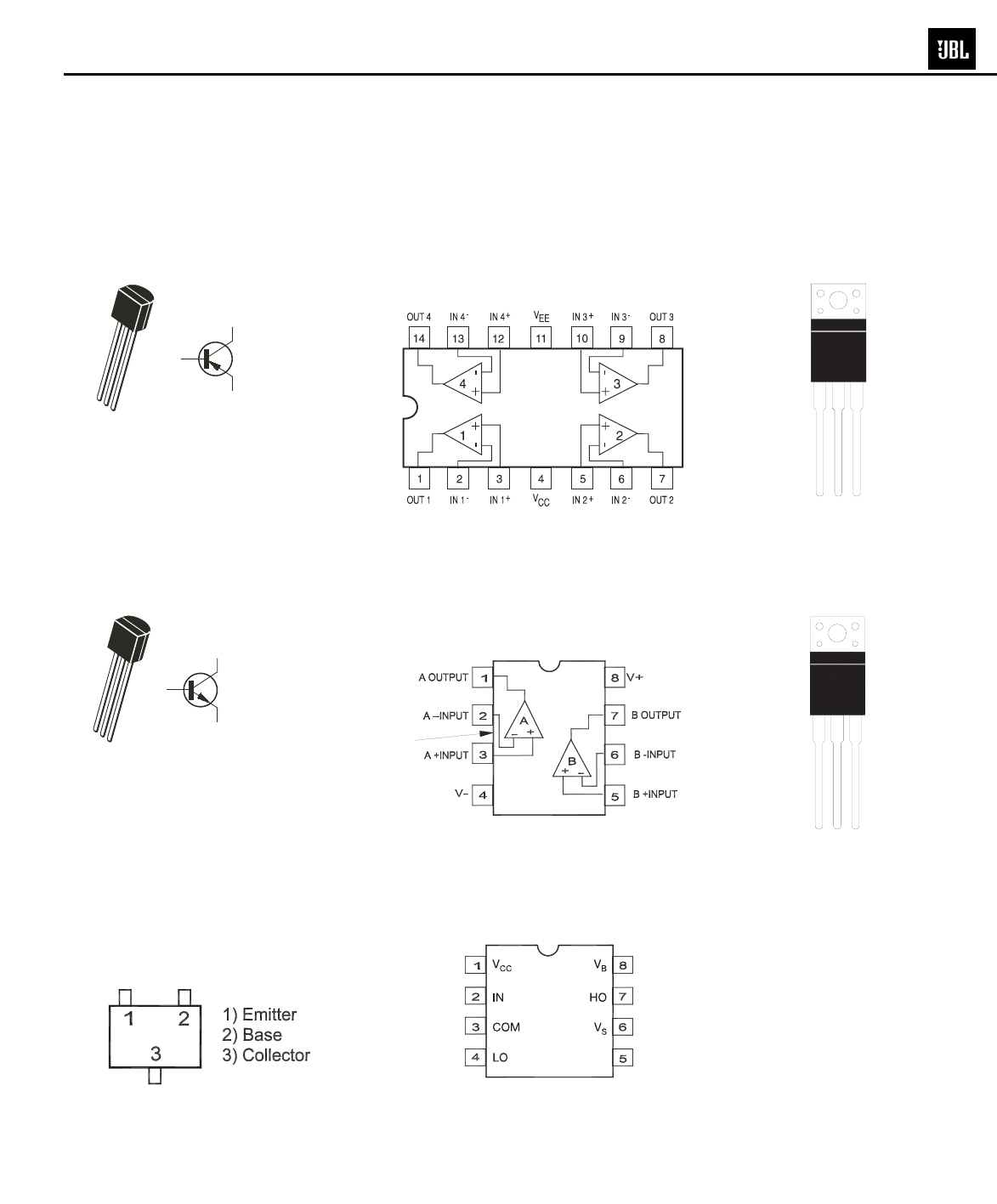
OPAMP, QUAD
TL074CDR
U2, 3
OPAMP, DUAL
TL072CDR SO-8,
NJM4558M-TE3
U5, 6, 4
IR2111 HALF-BRIDGE
DRIVER
U7
2
Base
3 Collector
1 Emitter
123
2N5401
Q1
2
Base
3 Collector
1 Emitter
123
MPSW06RLRA,
MPSW56RLRAMPQ,
MPS2222ARLRA,
2N2907A, 2N5551,
Q2, 16, 3, 21, 19, 23, 17
MOSFET IRF640
Q18, 22
TIP31C
Q4
MMBT3904LTI SOT23,
MMBT3906LTI SOT23,
DTC114EK SMT3,
MMBT5401 LTI,
MMBT5551 LTI
Q11, 14, 13, 5, 8, 9, 6, 10,
12, 15, 7, 20, 24, 26, 25
BEVEL
1. G
2. D
3. S
123
BC
E
Semiconductor Pinout Diagrams
28
E250P/P12SW subwoofers
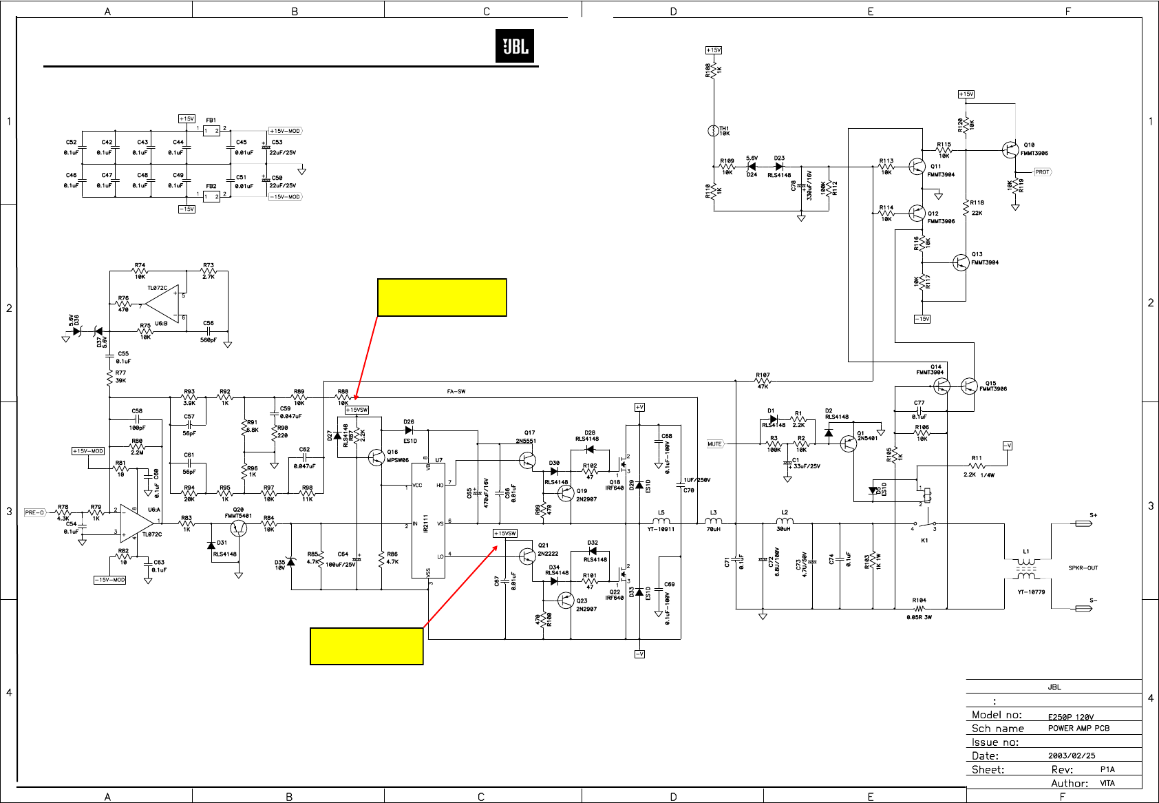
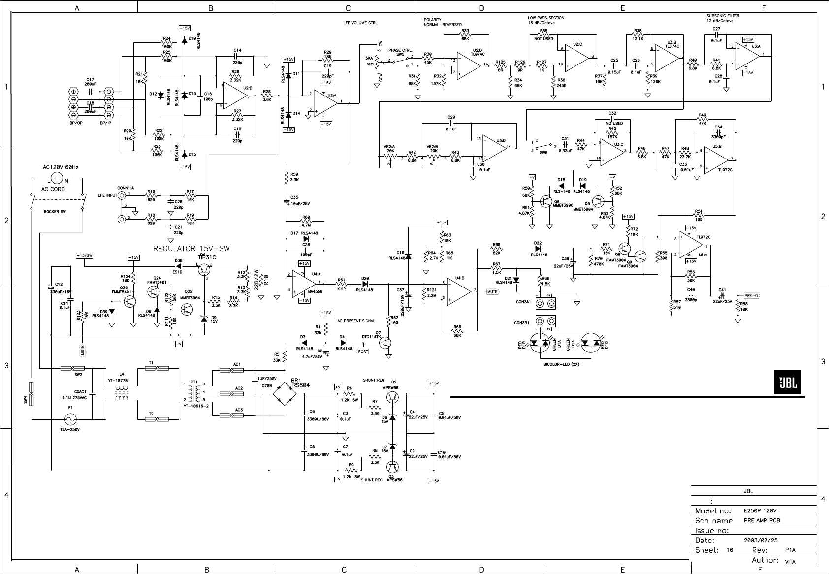
SCHEMATICS
NOTE: THIS VOLTAGE IS
REFERENCED TO -V,
NOT CIRCUIT GROUND
NOTE: THIS VOLTAGE IS
REFERENCED TO -V,
NOT CIRCUIT GROUND
29
E250P/P12SW subwoofers
P12SW Value of C65 = 47uf
See service bulletin for E250P
30
E250P/P12SW subwoofers
NOTE: THIS VOLTAGE IS
REFERENCED TO -V,
NOT CIRCUIT GROUND
