JBL 104 User Guide
JBL_104_User_Guide JBL One Series 104 (Pair) | Compact Powered Desktop Reference Monitors
User Manual: JBL JBL One Series 104 | Compact Powered Desktop Reference Monitors
Open the PDF directly: View PDF ![]() .
.
Page Count: 16
User's Guide
104
Master Monitor
104
Extension Monitor


3
Table of Contents
Section 1: Important Safety Instructions ���������������������������������������������������������������������������������������������������������������4
Section 2: Introduction �������������������������������������������������������������������������������������������������������������������������������������������5
JBL Coaxial Transducer .................................................................................................................................. 5
Features .......................................................................................................................................................... 5
JBL Professional Reliability ............................................................................................................................5
Section 3: Setting Up Your System ������������������������������������������������������������������������������������������������������������������������ 6
Included Items ................................................................................................................................................6
Placement .......................................................................................................................................................6
Audio Connections .........................................................................................................................................7
Making Sound.................................................................................................................................................7
Section 4: Features and Functions ������������������������������������������������������������������������������������������������������������������������8
Section 5: Standby Mode �������������������������������������������������������������������������������������������������������������������������������������10
Disabling and Enabling Standby Mode ........................................................................................................10
Section 6: Troubleshooting �����������������������������������������������������������������������������������������������������������������������������������11
Section 7: Specifications ��������������������������������������������������������������������������������������������������������������������������������������12
Section 8: Graphs �������������������������������������������������������������������������������������������������������������������������������������������������13
Frequency Response .................................................................................................................................... 13
Section 9: Contact Information ����������������������������������������������������������������������������������������������������������������������������14
Section 10: Warranty Information �������������������������������������������������������������������������������������������������������������������������15
4
Section 1: Important Safety Instructions
1. READ these instructions.
2. KEEP these instructions.
3. HEED all warnings.
4. FOLLOW all instructions.
5. DO NOT use this apparatus near water.
6. CLEAN ONLY with dry cloth.
7. DO NOT block any ventilation openings. Install in accordance with the manufacturer’s
instructions.
8. DO NOT install near any heat sources such as radiators, heat registers, stoves, or other
apparatus (including ampliers) that produce heat.
9. DO NOT defeat the safety purpose of the polarized or grounding type plug. A polarized
plug has two blades with one wider than the other. A grounding type plug has two
blades and a third grounding prong. The wider blade or the third prong are provided for
your safety. If the provided plug does not t into your outlet, consult an electrician for
replacement of the obsolete outlet.
10. PROTECT the power cord from being walked on or pinched, particularly at plugs,
convenience receptacles, and the point where they exit from the apparatus.
11. ONLY USE attachments/accessories specied by the manufacturer.
12.
USE ONLY with a cart, stand, tripod, bracket, or table specied by the
manufacturer, or sold with the apparatus. When a cart is used, use caution
when moving the cart/apparatus combination to avoid injury from tip-over.
13. UNPLUG this apparatus during lightning storms or when unused for long periods of time.
14. REFER all servicing to qualied service personnel. Servicing is required when the
apparatus has been damaged in any way, such as power-supply cord or plug is
damaged, liquid has been spilled or objects have fallen into the apparatus, the apparatus
has been exposed to rain or moisture, does not operate normally, or has been dropped.
15. DO NOT expose this apparatus to dripping or splashing and ensure that no objects lled
with liquids, such as vases, are placed on the apparatus.
16. To completely disconnect this apparatus from the AC Mains, disconnect the power supply
cord plug from the AC receptacle.
17. Where the mains plug or an appliance coupler is used as the disconnect device, the
disconnect device shall remain readily operable.
18. DO NOT overload wall outlets or extension cords beyond their rated capacity as this can
cause electric shock or re.
The exclamation point, within an equilateral triangle, is intended to alert the user
to the presence of important operating and maintenance (servicing) instructions
in the literature accompanying the product.
The lightning ash with arrowhead symbol within an equilateral triangle is
intended to alert the user to the presence of uninsulated “dangerous voltage”
within the product’s enclosure that may be of sufcient magnitude to constitute
a risk of electrical shock to persons.
ESD Warning: The icon to the left indicates text regarding potential danger
associated with the discharge of static electricity from an outside source (such
as human hands) into an integrated circuit, often resulting in damage to the
circuit.
WARNING: To reduce the risk of re or electrical shock, do not expose this apparatus to rain
or moisture.
WARNING: No naked ame sources – such as lighted candles – should be placed on the
product.
WARNING: Equipment shall be connected to a MAINS socket outlet with a protective
earthing connection.
CAUTION: To reduce the risk of electric shock, grounding of the center pin of this plug must
be maintained.
WARNING: This product is intended to be operated ONLY from the voltages listed on the
back panel or the recommended, or included, power supply of the product. Operation from
other voltages other than those indicated may cause irreversible damage to the product and
void the products warranty. The use of AC Plug Adapters is cautioned because it can allow
the product to be plugged into voltages in which the product was not designed to operate. If
you are unsure of the correct operational voltage, please contact your local distributor and/or
retailer. If the product is equipped with a detachable power cord, use only the type provided,
or specied, by the manufacturer or your local distributor.
FCC AND CANADA EMC COMPLIANCE
INFORMATION:
This device complies with part 15 of the FCC Rules. Operation is
subject to the following two conditions:
(1) This device may not cause harmful interference, and
(2) this device must accept any interference received, including
interference that may cause undesired operation.
NOTE: This equipment has been tested and found to comply with
the limits for a Class B digital device, pursuant to part 15 of the FCC
Rules. These limits are designed to provide reasonable protection
against harmful interference in a residential installation. This
equipment generates, uses and can radiate radio frequency energy
and, if not installed and used in accordance with the instructions,
may cause harmful interference to radio communications. However,
there is no guarantee that interference will not occur in a particular
installation. If this equipment does cause harmful interference to
radio or television reception, which can be determined by turning the
equipment off and on, the user is encouraged to try to correct the
interference by one or more of the following measures:
• Reorient or relocate the receiving antenna.
• Increase the separation between the equipment and receiver.
• Connect the equipment into an outlet on a circuit different from
that to which the receiver is connected.
• Consult the dealer or an experienced radio/TV technician for
help.
Approved under the verication provision of FCC Part 15 as a Class
B Digital Device.
Caution: Changes or modications not expressly approved by the
manufacturer could void the user’s authority to operate this device.
CAN ICES-3 (B)/NMB-3(B)
EU COMPLIANCE INFORMATION:
Hereby, Harman Professional declares that the equipment type JBL
104 Reference Monitors, bearing the CE Mark are in compliance with
the following:
• European Union Low Voltage Directive 2014/35/EU
• European Union EMC Directive 2014/30/EU
• European Union Restriction of Hazardous Substances Recast
(RoHS2) Directive 2011/65/EU
• European Union Eco-Design 1275/2008
• European Union Eco-Design 801/2013
• European Union Registration, Evaluation, Authorization and
Restriction of Chemicals (REACH) Directive 1907/2006
The full text of the EU declaration of conformity is available at the
following Internet address: http://www.jblpro.com/www/product-support/
downloads
WARNING: Do Not Open! Risk of Electrical Shock. Voltages in
this equipment are hazardous to life. No user-serviceable parts
inside. Refer all servicing to qualied service personnel.
Place the equipment near a main power supply outlet and make
sure that you can easily access the power breaker switch.
WEEE NOTICE:
This appliance is labeled in accordance with
European Directive 2012/19/EU concerning waste
of electrical and electronic equipment (WEEE).
This label indicates that this product should not
be disposed of with household waste. It should
be deposited at an appropriate facility to enable
recovery and recycling.

5
Section 2: Introduction
Congratulations on your purchase of JBL Professional 104 Reference Monitors. These monitors meet JBL’s
high standards for accuracy and long-term reliability in demanding applications. All 104 Reference Monitors
incorporate JBL Professional transducer technologies to provide accurate frequency response, low frequency
extension and impressive output for their compact size. Each speaker is equipped to interface with a range of
signal sources, including high-output professional audio equipment.
JBL COAXIAL TRANSDUCER
The heart of the system is an innovative 4.5" JBL coaxial transducer that provides several benets:
• The coaxial high and low frequency transducer design delivers smooth, extended frequency response
from 60 Hz to 20 kHz, in a compact, integrated form factor.
• The low frequency cone is precisely contoured to serve as the "wave guide," delivering detailed imaging
and a broad sweet spot so you don't have to sit directly in front of the speakers to hear accurate and
natural sound.
FEATURES
The JBL 104 Reference Monitors include a range of features for professional audio production where accuracy
and a compact form factor are essential:
• JBL coaxial 4.5" low-frequency and integrated high-frequency transducers deliver extended frequency
response and detailed imaging
• Integrated 60-watt power amplier, with 30 watts driving each speaker for impressive output
• 60 Hz – 20 kHz frequency range, acoustically optimized to provide neutral performance when placed on a
desktop or work surface
• Balanced 6.5 mm (1/4”) and unbalanced 3.5 mm (1/8") inputs allow connection of a broad range of
professional and consumer audio equipment
• Front-panel AUX IN jack allows convenient connection of personal music players, mobile phones and
other audio playback sources
• Front-panel VOLUME control
• Front-panel HEADPHONE jack with automatic speaker mute feature
• The MASTER MONITOR includes an integrated power supply, power inlet and all the electronics for the
EXTENSION MONITOR, eliminating clutter
JBL PROFESSIONAL RELIABILITY
Prior to becoming a production-ready design, the 104 Reference Monitors are subjected to JBL’s tough 100-
hour power test, in which the speakers are required to play continuously at full output for 100 hours without
failure. This demanding test ensures the 104 Reference Monitors deliver years of reliable performance. To get
the most out of your speakers, please review this user's guide and keep it on hand for future reference. Also,
please register your new speakers at www.jblpro.com/registration.
6
INCLUDED ITEMS
• 1 x 10⁴ Master Monitor
• 1 x 10⁴ Extension Monitor
• 1 x Extension Monitor Connection Wire
• 1 x Audio Connection Cable: 3.5 mm (1/8") mini TRS stereo plug to dual RCA plug
• 1 x Power Cord
• 1 x Quick Setup Guide
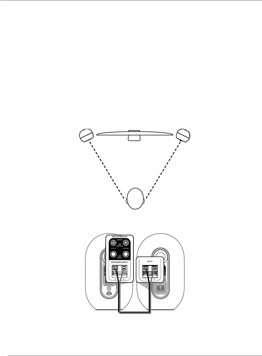
PLACEMENT
104 Reference Monitors are designed to deliver detailed imaging when placed on your work surface. To get the
most out of your speakers, follow these recommendations:
• Place speakers on your work surface with the MASTER MONITOR in close proximity to a power outlet.
Position the speakers at arms length, to form an equilateral triangle with the listening position. Angle each
speaker so it it is aimed at your listening position.
• Using the supplied wire, connect the EXTENSION MONITOR to the MASTER MONITOR by inserting the
positive (red) wire and the negative (black) wire in the corresponding terminals on both speakers.
EXTENSIONMASTER
• Connect the power cord to the POWER inlet located on the rear of the MASTER MONITOR. Connect the
power cord plug to a suitable power outlet.
Section 3: Setting Up Your System

7
AUDIO CONNECTIONS
NOTE: Before making audio connections, ensure the VOLUME control on the 104 MASTER MONITOR is set to
the full counter-clockwise (minimum) position.
The 104 MASTER MONITOR is equipped with 6 mm (1/4") TRS inputs for connection of balanced and
unbalanced professional audio products with high-level outputs (up to +4 dBu nominal), such as professional
computer audio interfaces, mixing consoles and audio production equipment. Dual RCA connectors allow
connection of unbalanced consumer audio products with consumer-level signal levels (-10 dBV nominal), such
as personal music players, consumer audio receivers and audio visual equipment.
Additionally, a 3.5 mm (1/8") stereo AUX input is provided on the front of the MASTER MONITOR, allowing
convenient connection of personal music players and smart phones.
NOTE: To determine the nominal output level of the connected equipment, consult the documentation supplied
with the connected equipment.
NOTE: Although multiple inputs are provided, you should connect only one playback device at any time.
Connection of multiple playback devices may degrade audio playback quality.
MAKING SOUND
1. The front of the MASTER MONITOR is equipped with a VOLUME control that can be used to adjust the
playback level. Ensure the VOLUME control is set to the full counter-clockwise (minimum) position.
2. Power on the connected audio equipment (mixing console, computer audio interface, preamp, etc.).
3. Set the POWER switch on to the ON position. After a short delay, the POWER LED on the front of the
MASTER MONITOR will illuminate and the speakers will be ready to reproduce audio signals.
4. Play full range program material from the source and slowly advance the VOLUME control on the
MASTER MONITOR until a comfortable listening level is achieved.
8
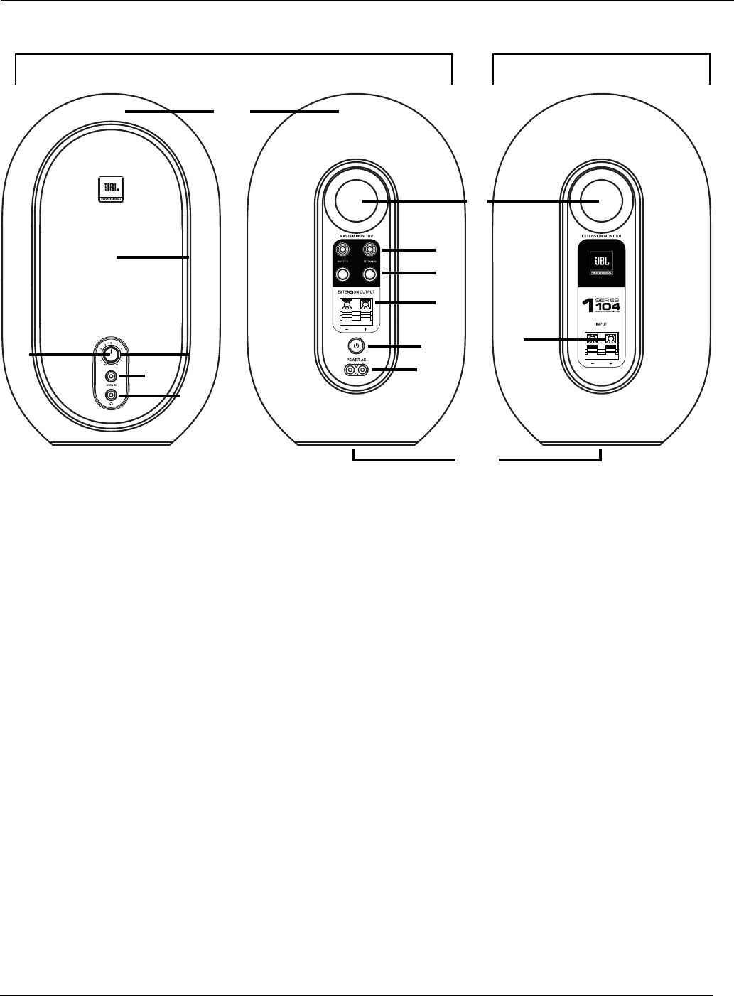
Master Monitor
Front Rear
Extension Monitor
Rear
1
6
14
7
8
9
10
11
12
2
45
313
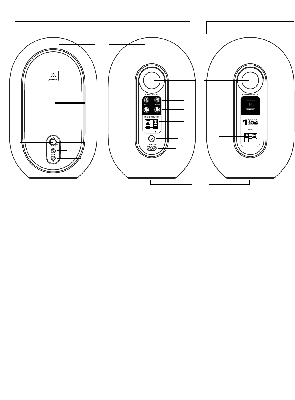
1. COAXIAL TRANSDUCER (SPEAKER) – Separate high and low frequency transducers are mounted in a
single frame to create a full range speaker that reproduces the entire audio range.
2. POWER INDICATOR – Illuminates when power is connected and the POWER switch is set to ON.
NOTE: The POWER indicator appears partially illuminated when the MASTER MONITOR is in Standby
Mode.
3. VOLUME CONTROL – Use this control to set the maximum listening level. This control is also used to
enable and disable Standby Mode.
4. AUX INPUT– Connect equipment with a 3.5 mm (1/8") stereo connector, such as personal music players
and smart phones, to this input.
5. HEADPHONE OUTPUT – Connect headphones with a 3.5 mm ( 1/8") stereo connector to this output.
NOTE: Connecting headphones to the HEADPHONE output will mute the speakers.
6. LOW FREQUENCY PORTS – The patented Slip Stream™ Port works in conjunction with the transducer
to provide accurate low frequency performance.
7. RCA INPUTS – Connect consumer equipment to these inputs using unbalanced RCA cables.
NOTE: Signal connected to the RCA input labelled "MASTER" will be reproduced by the MASTER
MONITOR. Signal connected to the RCA input labelled "EXTENSION" will be reproduced by the
EXTENSION Monitor. These inputs are designed to accept signals with -10 dBV nominal level.
Section 4: Features and Functions
9
Master Monitor
Front Rear
Extension Monitor
Rear
1
6
14
7
8
9
10
11
12
2
45
313
8. 6.5 MM (1/4”) TRS INPUTS – Connect professional equipment to these inputs using balanced or
unbalanced 6.5 mm (1/4”) cables.
NOTE: Signal connected to the TRS (Tip Ring Sleeve) input labelled "MASTER" will be reproduced by
the MASTER MONITOR. Signal connected to the TRS input labelled "EXTENSION" will be reproduced by
the EXTENSION MONITOR. These inputs are designed to accept signals with a +4 dBu nominal level, or
lower.
9. EXTENSION OUTPUT – Connect this output to the EXTENSION MONITOR using the included speaker
wire. This output sends an amplied speaker-level signal to the EXTENSION MONITOR.
10. POWER SWITCH – Activates power for the system.
11. POWER INLET – Connect the included AC power cord to this inlet.
12. ENCLOSURE – The hard-shell enclosure provides the acoustic volume required by the monitors for
accurate reproduction. The MASTER MONITOR enclosure also houses the power amplier and electrical
components.
13. EXTENSION INPUT – Connect this input to the MASTER MONITOR EXTENSION OUTPUT terminals
using the included speaker wire. This input receives an amplied speaker-level signal from the MASTER
MONITOR.
14. ISOLATION PAD – A rubber isolation pad on the bottom of each monitor minimizes mechanical
interaction between the speaker and the work surface, reducing acoustic resonance and optimizing
playback performance.
NOTE: Important product information, including the serial number, is printed and can be viewed on the
MASTER MONITOR isolation pad.

10
The JBL 104 Reference Monitors are equipped with a low-power "Standby Mode” that automatically reduces
the power consumption when signal is not detected for a period of 19 minutes. Once in Standby Mode, normal
operation is restored when signal is detected. It is normal to experience a momentary delay prior to resumption
of audio. Standby Mode is enabled by default, but it can be disabled for professional applications that require
the speakers to be fully operational at all times. Standby Mode can be disabled/enabled using the procedures
listed below.
DISABLING AND ENABLING STANDBY MODE
To disable Standby Mode, use the following procedure:
1. Set POWER switch to the OFF position.
2. Connect headphones to the HEADPHONE output on the MASTER MONITOR.
3. Set the VOLUME control to the minimum (full counter-clockwise) setting.
4. Set the POWER switch to the ON position. Within a period of 15 seconds complete the following steps:
a. Disconnect the headphones.
b. Reconnect the headphones.
c. Disconnect headphones again.
d. Reconnect headphones again.
NOTE: This procedure must be completed within 15 seconds after performing Step 4. The POWER LED
will ash rapidly 5 times to indicate the process is complete.
To re-enable Standby Mode, use the following procedure:
1. Set POWER switch to the OFF position.
2. Disconnect headphones from the HEADPHONE output on the MASTER MONITOR.
3. Set the VOLUME control to the minimum (full counter-clockwise) setting.
4. Set the POWER switch to the ON position. Within a period of 15 seconds complete the following steps:
a. Connect the headphones.
b. Disconnect headphones.
c. Connect headphones again.
d. Disconnect headphones again.
NOTE: This procedure must be completed within 15 seconds after performing Step 4. The POWER LED
will ash slowly 2 times to indicate the process is complete.
5. Increase the setting of the VOLUME control (rotate clockwise).
6. Standby Mode will now be active, and after 19 minutes with no signal present, the 104 Reference
Monitors will enter Standby Mode.
Section 5: Standby Mode

11
Issue: There is no sound from the monitors.
• Conrm the power cable is connected to the MASTER MONITOR and the POWER switch is set to the ON
position.
• Make sure the POWER LED is illuminated on the front of the MASTER MONITOR.
• Make sure a signal source is connected to the MASTER MONITOR and that it is producing sound.
• Make sure the 104's VOLUME control is not set to the full counter-clockwise (minimum) position.
Issue: The signal is distorted.
• If the signal source is a professional product, capable of outputting high, +4 dBu signals, conrm the
signal source is connected to the 104's TRS inputs.
• Try reducing the 104's VOLUME control setting to see if the distortion persists at lower monitoring
levels. If the distortion does persist at lower levels, inspect the connected source device to determine if
the source of the distortion is external. If possible, try reducing the output signal level of the connected
device.
Issue: The signal level is low.
• Increase the setting of the 104's VOLUME control.
• Connect the signal source to the RCA Inputs.
If the above measures do not correct the problem, please contact JBL Professional Customer Service for
assistance.
Section 6: Troubleshooting

12
System Input Type: 1/8" Aux, RCA, 1/4" TRS balanced
System Output Type: 1/8" stereo headphone with auto speaker mute
LF Transducer: 4.5 in (118 mm)
HF Transducer: 0.75 in (19 mm), soft dome
Enclosure Type: Ported
Crossover: 1725 Hz, 1st order
Amplifier Power: 60 W (30 W each speaker), Class D
Sensitivity: 88 dB SPL @ 1 m with -10 dBV Aux In (Volume = Max)
System Maximum SPL*: 92 dB (continuous power measured)
System Peak SPL*: 102 dB (pink noise, 12 dB crest factor)
System Maximum SPL, Momentary*: 104 dB
Maximum Peak Input Level (-10 dBV / +4 dBu): +6 dBV / +20.3 dBu
Frequency Range (-3 dB)**: 88 Hz – 20 kHz
Frequency Range (-10 dB)**: 60 Hz – 20 kHz
System Rated Impedance: 8 Ω
Minimum Impedance: 7.8 Ω @ 260 Hz
Cabinet Tuning Frequency: 72 Hz
System Power Handling: 30 W x 2 @ 100 hours, IEC/SMS
System Distortion Criteria: <10% THD at maximum output with full compressor/
limiter engagement
Electrical Distortion Criteria: <0.2% THD @ 1 kHz / 2.83 VRMS output; <1% THD @ 1
kHz, full rated output
Signal To Noise Ratio: 75 dBA (A-Weighted), 70 dBr (unweighted), relative to 2.83
VRMS output on HF
Coverage (Horizontal x Vertical): 120º x 120º
System Polarity: EIA
Acoustic Test Specification: ATS# 1000340443
AC Input Voltage: 100–240 VAC ±10%, 50 / 60 Hz
Current Draw: 85 W
Electrical Current Draw (W) Idle 100 / 240 VAC: 3.52 / 3.70
Electrical Current Draw (W) Max Power 100 / 240 VAC: 80 / 80
Electrical Current Draw (W) Standby Mode 100 / 240 VAC: 0.34 / 0.46
Enclosure Material: ABS with metal grille
Enclosure Finish: Matte black acrylic paint
Enclosure Height: 9.72 in (247 mm)
Enclosure Width: 6.02 in (153 mm)
Enclosure Depth***: 4.88 in (124 mm)
Net Weight Master Monitor / Extension Monitor: 4.54 lb (2.06 kg) / 3.81 lb (1.73 kg)
Display Carton (H x W x D): 13.14 x 8.22 x 12.4 in (334 x 209 x 315 mm)
Shipping Carton (H x W x D): 13.46 x 8.54 x 12.99 in (342 x 217 x 330 mm)
Shipping Gross Weight: 10.56 lb (4.8 kg)
* Measured with full-bandwidth pink noise, C-Weighted
** Measured in half space
*** Measured without power cord and audio connectors
Section 7: Specications
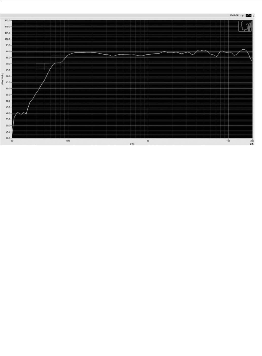
13
FREQUENCY RESPONSE
Section 8: Graphs

14
MAILING ADDRESS:
JBL Professional
8500 Balboa Blvd.
Northridge, CA 91329
SHIPPING ADDRESS:
JBL Professional
8370 Balboa Blvd., Dock D
Northridge, CA 91329
(Do not return product to this address without rst obtaining prior authorization from JBL)
CUSTOMER SERVICE:
Monday through Friday
8:00am - 5:00pm
Pacic Coast Time in the U.S.A.
(800) 8JBLPRO (800.852.5776)
www.jblproservice.com
PRODUCT REGISTRATION:
Register your product online at www.jblpro.com/registration
PROFESSIONAL CONTACTS, OUTSIDE THE USA:
Contact the JBL Professional Distributor in your area. A complete list of JBL Professional international
distributors is provided at our U.S.A. website: www.jblpro.com
EN DEHORS DES ETATS-UNIS:
Contacter votre Distributeur JBL Professional. Une liste complète de nos distributeurs internationaux est
disponible sur le site web - www.jblpro.com
INTERNATIONAL:
Wenden Sie sich an Ihre örtliche JBL Professional Vertretung. Eine vollständige Liste der internationalen JBL-
Vertretungen nden Sie auf unserer Website unter www.jblpro.com
FUERA DE LOS ESTADOS UNIDOS:
Comuníquese con el distribuidor de JBL Professional de su zona. En nuestro sitio web, www.jblpro.com,
encontrará una lista completa de los distribuidores de JBL International.
Section 9: Contact Information

15
The JBL Limited Warranty on professional loudspeaker products (except for enclosures) remains in effect for ve
years from the date of the rst consumer purchase. JBL ampliers are warranted for three years from the date
of original purchase. Enclosures and all other JBL products are warranted for two years from the date of original
purchase.
WHO IS PROTECTED BY THIS WARRANTY?
Your JBL Warranty protects the original owner and all subsequent owners so long as: A.) Your JBL product
has been purchased in the Continental United States, Hawaii or Alaska. (This Warranty does not apply to JBL
products purchased elsewhere except for purchases by military outlets. Other purchasers should contact the
local JBL distributor for warranty information.); and B.) The original dated bill of sale is presented whenever
warranty service is required.
WHAT DOES THE JBL WARRANTY COVER?
Except as specied below, your JBL Warranty covers all defects in material and workmanship. The following are
not covered: Damage caused by accident, misuse, abuse, product modication or neglect; damage occurring
during shipment; damage resulting from failure to follow instructions contained in your Instruction Manual;
damage resulting from the performance of repairs by someone not authorized by JBL; claims based upon any
misrepresentations by the seller; any JBL product on which the serial number has been defaced, modied or
removed.
WHO PAYS FOR WHAT?
JBL will pay all labor and material expenses for all repairs covered by this warranty. Please be sure to save
the original shipping cartons because a charge will be made if replacement cartons are requested. Payment of
shipping charges is discussed in the next section of this warranty.
HOW TO OBTAIN WARRANTY PERFORMANCE
If your JBL product ever needs service, write or telephone us at JBL Incorporated (Attn: Customer Service
Department), 8500 Balboa Boulevard, PO. Box 2200, Northridge, California 91329 (818/893-8411). We may
direct you to an authorized JBL Service Agency or ask you to send your unit to the factory for repair. Either way,
you’ll need to present the original bill of sale to establish the date of purchase. Please do not ship your JBL
product to the factory without prior authorization. If transportation of your JBL product presents any unusual
difculties, please advise us and we may make special arrangements with you. Otherwise, you are responsible
for transporting your product for repair or arranging for its transportation and for payment of any initial shipping
charges. However, we will pay the return shipping charges if repairs are covered by the warranty.
LIMITATION OF IMPLIED WARRANTIES
ALL IMPLIED WARRANTIES, INCLUDING WARRANTIES OF MERCHANTABILITY AND FITNESS FOR
PARTICULAR PURPOSE, ARE LIMITED IN DURATION TO THE LENGTH OF THIS WARRANTY.
EXCLUSION OF CERTAIN DAMAGES
JBL’S LIABILITY IS LIMITED TO THE REPAIR OR REPLACEMENT, AT OUR OPTION, OF ANY DEFECTIVE
PRODUCT AND SHALL NOT INCLUDE INCIDENTAL OR CONSEQUENTIAL DAMAGES OF ANY KIND. SOME
STATES DO NOT ALLOW LIMITATIONS ON HOW LONG AN IMPLIED WARRANTY LASTS AND/OR DO NOT
ALLOW THE EXCLUSION OF INCIDENTAL OR CONSEQUENTIAL DAMAGES, SO THE ABOVE LIMITATIONS
AND EXCLUSIONS MAY NOT APPLY TO YOU. THIS WARRANTY GIVES YOU SPECIFIC LEGAL RIGHTS, AND
YOU MAY ALSO HAVE OTHER RIGHTS, WHICH VARY, FROM STATE TO STATE.
JBL Professional
8500 Balboa Boulevard
Northridge, CA 91329 USA
Section 10: Warranty Information

Issue date: 1/2019
