JBL 3 Series MKII Owners Manual English
User Manual: JBL JBL 306P MkII | Powered 6 (15.24 cm) Two-Way Studio Monitor
Open the PDF directly: View PDF ![]() .
.
Page Count: 23
- Section 1: Important Safety Instructions
- Section 2: Introduction
- Section 3: Setting Up Your System
- Section 4: 305P, 306P, and 308P MkII Powered Studio Monitors
- Section 5: LSR310S Powered Studio Subwoofer
- Section 6: System Connections
- Section 7: Troubleshooting
- Section 8: Specifications
- Section 9: JBL Service Contact Information
- Section 10: Product Warranty Information
Owner's Manual
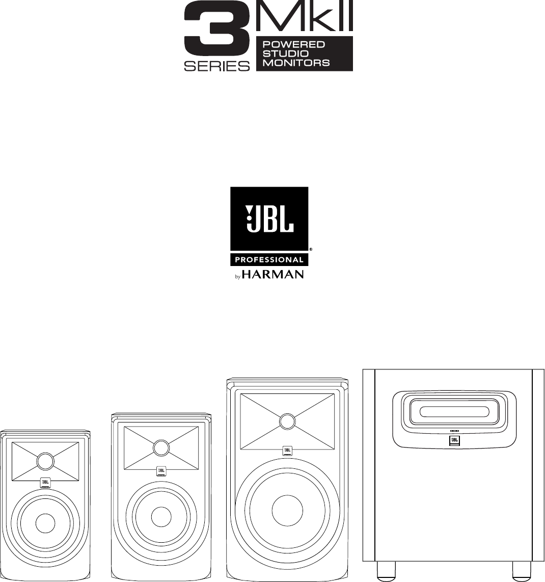
305P MkII
5" Powered
Studio Monitor
306P MkII
6" Powered
Studio Monitor
308P MkII
8" Powered
Studio Monitor
LSR310S
10" Powered
Studio Subwoofer


3
Table of Contents
Section 1: Important Safety Instructions ���������������������������������������������������������������������������������������������������������������4
Section 2: Introduction �������������������������������������������������������������������������������������������������������������������������������������������5
JBL Linear Spatial Reference (LSR) Design ...................................................................................................5
Image Control Waveguide .............................................................................................................................. 5
305P, 306P, and 308P MkII Features ..............................................................................................................5
LSR310S Powered Studio Subwoofer Features .............................................................................................6
JBL Professional Reliability ............................................................................................................................6
Section 3: Setting Up Your System ������������������������������������������������������������������������������������������������������������������������ 7
Each 3 Series Carton Includes the Following Items: ......................................................................................7
Unpacking.......................................................................................................................................................7
Placement .......................................................................................................................................................7
Audio Connections .........................................................................................................................................9
LSR310S Powered Studio Subwoofer Connections ......................................................................................9
Power Connections ........................................................................................................................................9
Making Sound.................................................................................................................................................9
Section 4: 305P, 306P, and 308P MkII Powered Studio Monitors ����������������������������������������������������������������������� 10
Features ........................................................................................................................................................ 10
Input Panel ....................................................................................................................................................11
Audio Connections .......................................................................................................................................11
Auto Standby Feature ...................................................................................................................................12
Section 5: LSR310S Powered Studio Subwoofer ������������������������������������������������������������������������������������������������13
Features ........................................................................................................................................................ 13
Input Panel ....................................................................................................................................................14
Audio Connections .......................................................................................................................................15
Setting the Subwoofer Level ........................................................................................................................15
Placement and Polarity Setting ....................................................................................................................15
Crossover Settings and Bass Management ................................................................................................16
Surround Sound Systems and LFE ..............................................................................................................16
Section 6: System Connections ���������������������������������������������������������������������������������������������������������������������������17
Two Channel Systems ..................................................................................................................................17
Surround Sound Systems .............................................................................................................................18
Section 7: Troubleshooting �����������������������������������������������������������������������������������������������������������������������������������19
Section 8: Specifications ��������������������������������������������������������������������������������������������������������������������������������������20
Section 9: JBL Service Contact Information��������������������������������������������������������������������������������������������������������21
Section 10: Product Warranty Information ���������������������������������������������������������������������������������������������������������� 22
4
Section 1: Important Safety Instructions
1. READ these instructions.
2. KEEP these instructions.
3. HEED all warnings.
4. FOLLOW all instructions.
5. DO NOT use this apparatus near water.
6. CLEAN ONLY with dry cloth.
7. DO NOT block any ventilation openings. Install in accordance with the manufacturer’s
instructions.
8. DO NOT install near any heat sources such as radiators, heat registers, stoves, or other
apparatus (including ampliers) that produce heat.
9. DO NOT defeat the safety purpose of the polarized or grounding type plug. A polarized
plug has two blades with one wider than the other. A grounding type plug has two
blades and a third grounding prong. The wider blade or the third prong are provided for
your safety. If the provided plug does not t into your outlet, consult an electrician for
replacement of the obsolete outlet.
10. PROTECT the power cord from being walked on or pinched, particularly at plugs,
convenience receptacles, and the point where they exit from the apparatus.
11. ONLY USE attachments/accessories specied by the manufacturer.
12.
USE ONLY with a cart, stand, tripod, bracket, or table specied by the
manufacturer, or sold with the apparatus. When a cart is used, use caution
when moving the cart/apparatus combination to avoid injury from tip-over.
13. UNPLUG this apparatus during lightning storms or when unused for long periods of time.
14. REFER all servicing to qualied service personnel. Servicing is required when the
apparatus has been damaged in any way, such as power-supply cord or plug is
damaged, liquid has been spilled or objects have fallen into the apparatus, the apparatus
has been exposed to rain or moisture, does not operate normally, or has been dropped.
15. DO NOT expose this apparatus to dripping or splashing and ensure that no objects lled
with liquids, such as vases, are placed on the apparatus.
16. To completely disconnect this apparatus from the AC Mains, disconnect the power supply
cord plug from the AC receptacle.
17. Where the mains plug or an appliance coupler is used as the disconnect device, the
disconnect device shall remain readily operable.
18. DO NOT overload wall outlets or extension cords beyond their rated capacity as this can
cause electric shock or re.
The exclamation point, within an equilateral triangle, is intended to alert the user
to the presence of important operating and maintenance (servicing) instructions
in the literature accompanying the product.
The lightning ash with arrowhead symbol within an equilateral triangle is
intended to alert the user to the presence of uninsulated “dangerous voltage”
within the product’s enclosure that may be of sufcient magnitude to constitute
a risk of electrical shock to persons.
ESD Warning: The icon to the left indicates text regarding potential danger
associated with the discharge of static electricity from an outside source (such
as human hands) into an integrated circuit, often resulting in damage to the
circuit.
WARNING: To reduce the risk of re or electrical shock, do not expose this apparatus to rain
or moisture.
WARNING: No naked ame sources – such as lighted candles – should be placed on the
product.
WARNING: Equipment shall be connected to a MAINS socket outlet with a protective
earthing connection.
CAUTION: To reduce the risk of electric shock, grounding of the center pin of this plug must
be maintained.
WARNING: This product is intended to be operated ONLY from the voltages listed on the
back panel or the recommended, or included, power supply of the product. Operation from
other voltages other than those indicated may cause irreversible damage to the product and
void the products warranty. The use of AC Plug Adapters is cautioned because it can allow
the product to be plugged into voltages in which the product was not designed to operate. If
you are unsure of the correct operational voltage, please contact your local distributor and/or
retailer. If the product is equipped with a detachable power cord, use only the type provided,
or specied, by the manufacturer or your local distributor.
FCC AND CANADA EMC COMPLIANCE
INFORMATION:
This device complies with part 15 of the FCC Rules. Operation is
subject to the following two conditions:
(1) This device may not cause harmful interference, and
(2) this device must accept any interference received, including
interference that may cause undesired operation.
NOTE: This equipment has been tested and found to comply with
the limits for a Class B digital device, pursuant to part 15 of the FCC
Rules. These limits are designed to provide reasonable protection
against harmful interference in a residential installation. This
equipment generates, uses and can radiate radio frequency energy
and, if not installed and used in accordance with the instructions,
may cause harmful interference to radio communications. However,
there is no guarantee that interference will not occur in a particular
installation. If this equipment does cause harmful interference to
radio or television reception, which can be determined by turning the
equipment off and on, the user is encouraged to try to correct the
interference by one or more of the following measures:
• Reorient or relocate the receiving antenna.
• Increase the separation between the equipment and receiver.
• Connect the equipment into an outlet on a circuit different from
that to which the receiver is connected.
• Consult the dealer or an experienced radio/TV technician for
help.
Approved under the verication provision of FCC Part 15 as a Class
B Digital Device.
Caution: Changes or modications not expressly approved by the
manufacturer could void the user’s authority to operate this device.
CAN ICES-3 (B)/NMB-3(B)
EU COMPLIANCE INFORMATION:
Hereby, Harman Professional declares that the equipment type JBL 305P
MKII, 306P MKII, 308P MKII, bearing the CE Mark are in compliance with
the following:
• European Union Low Voltage Directive 2014/35/EU
• European Union EMC Directive 2014/30/EU
• European Union Restriction of Hazardous Substances Recast (RoHS2)
Directive 2011/65/EU
• European Union Eco-Design 1275/2008
• European Union Eco-Design 801/2013
• European Union Registration, Evaluation, Authorization and Restriction
of Chemicals (REACH) Directive 1907/2006
The full text of the EU declaration of conformity is available at the following
Internet address: http://www.jblpro.com/www/product-support/downloads
WARNING: Do Not Open! Risk of Electrical Shock. Voltages in
this equipment are hazardous to life. No user-serviceable parts
inside. Refer all servicing to qualied service personnel.
Place the equipment near a main power supply outlet and make
sure that you can easily access the power breaker switch.
WEEE NOTICE:
This appliance is labeled in accordance with
European Directive 2012/19/EU concerning waste
of electrical and electronic equipment (WEEE).
This label indicates that this product should not
be disposed of with household waste. It should
be deposited at an appropriate facility to enable
recovery and recycling.

5
Section 2: Introduction
Congratulations on your purchase of JBL Professional 3 Series Studio Monitors. The 3 Series meet JBL’s high
standards for accuracy and long-term reliability in demanding professional applications. All 3 Series models
incorporate JBL Professional transducer and network technologies to provide accurate frequency response,
exceptional low frequency extension and high SPL capability. JBL Linear Spatial Reference (LSR) design
ensures greater accuracy at the mix position in acoustically varied workspaces and production environments.
Additionally, each speaker is equipped to interface with a range of signal sources, including high-output
professional audio equipment.
JBL LINEAR SPATIAL REFERENCE (LSR) DESIGN
Because listening environments vary, JBL designed the 3 Series system using Linear Spatial Reference design
criteria that improve accuracy at the listening position in a broad range of rooms. The key to accuracy is
ensuring that not only the on-axis sound is neutral, but also the reected sound reaching the mix position is
neutral.
While most manufacturers take only a single on-axis measurement of the speaker’s performance, Linear Spatial
Reference design criteria requires 72 measurements, taken 360 degrees around the speaker, yielding 1,200
times more data. This data is used in the design of critical system components, enabling JBL to engineer
complete systems that deliver smooth off-axis response. The result: clear, accurate sound at the listening
position in any room.
IMAGE CONTROL WAVEGUIDE
JBL’s revolutionary Image Control Waveguide gives the 3 Series Powered Studio Monitors remarkable imaging,
a wide soundstage, and a solid “phantom center”. Subtle details can be heard, even in a dense mix. As an
added benet, the Image Control Waveguide provides a broad “sweet spot”, so you don’t have to be seated
directly in front of the speakers to hear accurate and natural and open sound.
305P, 306P, AND 308P MKII FEATURES
3 Series MkII models include a range of features to meet the needs of demanding audio production applications:
• The magnetically-shielded low frequency transducers in MkII models, equipped with 1.5" voice coils and
robust motor structures ne tuned for increased linearity, deliver excellent low frequency performance. By
reducing thermal-related effects, the 3 Series MkII Studio Monitors and LSR310S Subwoofer sound the
same at low, medium, and high levels. The woofers are magnetically shielded to prevent interference with
magnetically sensitive displays and equipment. The woofer’s self-repairing dust dome is resistant to dents
caused by ngers or external objects.
• JBL’s patented Slip Stream™ low frequency port design works in concert with the woofer to produce
deep bass response at any playback level. The double-ared shape of the port is precisely engineered for
greater low frequency extension and reduced turbulence.
• The bi-amplied design, with individual power ampliers for the low frequency and high frequency
transducers, uses efcient high-output Class-D integrated power ampliers to provide high SPL (sound
pressure level).
• Magnetically-shielded soft dome high frequency transducers with optimally damped materials improve
transient response and minimize distortion. By reducing distortion in the lower operating range, where the
ear is most sensitive, these transducers reduce ear fatigue.
• Balanced XLR and ¼" input connectors.
• +4dBu / -10dBV INPUT SENSITIVITY switch allows connection to consumer-grade or high-output
professional equipment without danger of input overload.
• Detented VOLUME attenuator allows ne adjustment of levels for a broad range of signal sources.
• HIGH FREQUENCY TRIM control to adjust the high frequency response to taste or compensate for
acoustically reective or absorptive listening environments.
• BOUNDARY EQ switch compensates for low-frequency acoustic anomalies that can occur when
loudspeakers are in close proximity to walls.

6
LSR310S POWERED STUDIO SUBWOOFER FEATURES
Producing extended low frequency response into the 20Hz region, the LSR310S is the perfect match for the 3
Series MkII studio monitors. The LSR310S feature set includes:
• A Magnetically-shielded low frequency transducer, equipped with a 1.5" voice coil and robust motor
structure for excellent low frequency performance. By reducing thermal-related effects, the 3 Series MkII
Studio Monitors and LSR310S Subwoofer sound the same at low, medium, and high levels. The woofer
is magnetically shielded to prevent interference with magnetically sensitive displays and equipment. The
woofer’s self-repairing dust dome is resistant to dents caused by ngers or external objects.
• A custom-designed down-ring, high-excursion 10" woofer with additional bucking magnet.
• A 200 watt Class-D power amplier with abundant output and dynamic headroom for the most demanding
production styles.
• The patented Slip Stream low frequency port, designed to work in concert with the 3 Series MkII woofers
for accurate bass response at all playback levels.
• A detented VOLUME control, making it easy to balance the LSR310S with the studio monitor system.
• Balanced XLR and ¼" input connectors.
• Two XLR output connectors to add the LSR310S to any studio monitor system and extend its low
frequency response.
• A +4dBu / -10dBV INPUT SENSITIVITY switch for connection to consumer or high-output professional
equipment without danger of input overload.
• Three CROSSOVER settings:
• 80Hz – This setting implements high- and low-pass lters to create a seamless blend of the
LSR310S with the 3 Series MkII studio monitors or other speaker system.
• XLF – This special setting activates a 120Hz high-pass lter in conjunction with a low frequency
tuning that approximates the tuning used in club playback systems. Using this setting, the bass
output more than doubles.
• External – The external setting bypasses all ltering, allowing use of an external active crossover.
• A protective limiting circuit allows the subwoofer to operate continuously at full output without failure.
JBL PROFESSIONAL RELIABILITY
Prior to becoming a production-ready design, each 3 Series model is subjected to JBL’s tough 100-hour
power test, in which the speaker is required to play continually at full output for 100 hours without failure. This
demanding test ensures the 3 Series speakers will deliver years of reliable performance. To get the most out
of the JBL 3 Series, please review this owner’s manual and keep it on hand for future reference. Also, please
register your new speakers at www.jblpro.com/registration.

7
EACH 3 SERIES CARTON INCLUDES THE FOLLOWING ITEMS:
• One 3 Series MkII studio monitor or 3 Series subwoofer
• One power cord
• Quick setup guide
• Four peel-off rubber pads (305P, 306P, and 308P MkII models only)
UNPACKING
When removing a speaker from its packaging, we recommend the following procedure, which will prevent
damage of the high frequency transducer:
305P, 306P, and 308P MkII models:
1. Remove the outer shipping carton, if one exists.
2. Place the inner carton on the oor with the top facing upwards.
3. Open the top of the box.
4. Without removing the internal packaging end-cap, gently rotate the carton so the open end rests on the
oor and the bottom of the carton is facing you.
5. Gently lift the carton and allow the speaker and protective end-cap to slide out of the carton and remain
on the oor.
6. Save the cartons and use the above procedure in reverse when you want to repack the units for
shipment.
LSR310S subwoofer – The subwoofer weighs 19 kg (42 lbs). Unpacking the subwoofer does not require you to
lift the subwoofer. However, you will need to rotate the subwoofer in the carton. If you are unable to perform the
following steps without assistance, please request help from another person.
1. Remove the outer shipping carton, if one exists.
2. Place the carton on the oor with the bottom facing upward.
3. Open the bottom aps of the carton and remove any protective packing materials from the bottom of the
subwoofer. Open the bag that protects the subwoofer to expose the subwoofer’s four feet.
4. Gently rotate the carton so the bottom is facing the oor and the four feet of the subwoofer are in contact
with the oor.
5. Gently lift the carton and allow the subwoofer and protective packing materials to slide out and remain on
the oor.
6. Remove the protective packing materials and documentation from the top of the subwoofer. Save the
carton and use the above procedure in reverse when you want to repack the unit for shipment.
PLACEMENT
3 Series MkII Studio Monitors are designed to deliver exceptional imaging in any room. To get the most out of
your speakers, follow these recommendations:
• Locate the four self-adhesive rubber pads supplied with the 305P, 306P, and 308P MkII speakers. Position
and attach these to the bottom surface of the speaker close to each corner.
• Position each 305P, 306P, or 308P MkII Studio Monitor in a vertical orientation with the tweeter on top.
Vertical orientation eliminates phase shift and acoustic cancellation of frequencies that can occur when
the distance of the woofer to the ear is different from the distance of the tweeter to the ear.
• Angle the speakers so the high-frequency transducer in each speaker is aimed directly towards the ear
of the listener.
Section 3: Setting Up Your System
8
• Ideally, 3 Series MkII Studio Monitors should be placed on suitable speaker stands, rather than on the
work surface. This will reduce resonance and deterioration of low frequency performance caused by the
speaker’s mechanical coupling with the work surface.
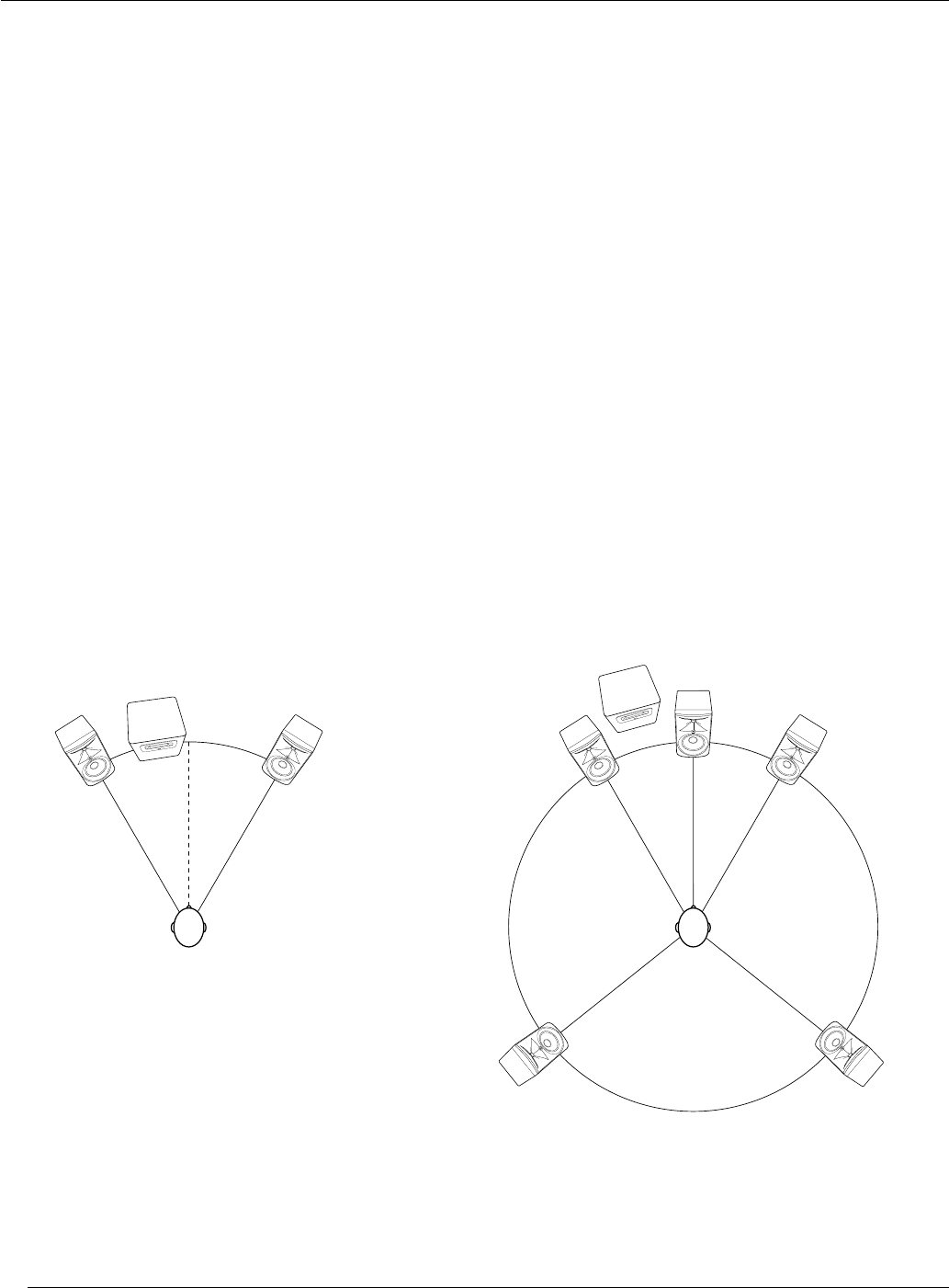
• For optimum imaging, the left and right speakers should be placed symmetrically in the room,
so each speaker is the same distance from adjacent walls and reective surfaces.
• The speakers should be placed so the position of the listener and the two speakers form an equilateral
triangle. Adjusting the distance between the speakers will affect the quality of bass heard at the listening
position. You can experiment with speaker placement to nd the placement that produces the preferred
bass response, imaging, and—when listening to stereo material—produces a strong “phantom center", in
which vocals and some instruments seem to originate from a point between speakers.
• The listening distance can be determined according to your preference, the acoustics of your room, and
the maximum SPL (sound pressure level) you want to hear at the listening position. You can nd the
speaker’s maximum SPL at 1 meter in the Specications section at the end of this manual. Each doubling
of listening distance will reduce the SPL at the listening position by as much as 6dB in an acoustically
absorptive room, but only 3 or 4dB in an acoustically reective room.
LSR310S subwoofer placement: The low frequency driver of the LSR310S is mounted on the bottom panel of
the subwoofer. Before placing the subwoofer, make sure the position on the oor is free of any large objects that
can interfere with or damage the woofer.
In a stereo system, the LSR310S subwoofer should be placed directly on the oor, located between the left
and right speakers. In a surround sound system, the subwoofer can be located between the left and center or
between the right and center channel speakers. The distance of the subwoofer from the listening position can
be adjusted to produce the optimum bass in the system. Placing the subwoofer close to a wall or in a corner
generally will increase the amount of bass heard in the room. Experiment to determine the Subwoofer placement
that produces the best balance and quality of bass in the system.
MIX POSITION MIX POSITION
LEFT
SUB / LFE
RIGHT
CENTER
LEFT
SURROUND
RIGHT
SURROUND
LEFT
SUB / LFE
RIGHT

9
AUDIO CONNECTIONS
NOTE: Before making audio connections, ensure the VOLUME control on each 3 Series speaker/subwoofer is
set to the full counter-clockwise (minimum) position.
The 3 Series speakers are equipped with balanced XLR and 6mm (¼") TRS inputs for connection to professional
computer audio interfaces, mixing consoles, and audio production equipment, as well as unbalanced consumer
audio products such as personal music players, consumer audio receivers, and audio visual equipment.
Connect professional equipment with balanced outputs to the XLR or 6mm (¼") TRS input of the speaker using
balanced audio cables.
3 Series speakers are equipped with an INPUT SENSITIVITY switch, which is set to the -10dBV setting at the
factory. This setting will be best for many applications. However, you should set the switch to the +4dBu setting
under the following conditions:
• When connecting 3 Series speakers to professional equipment with +4dBu nominal output level. To
determine the nominal output level of the connected equipment, consult the documentation supplied with
the connected equipment.
• The sound is distorted, even when the speaker VOLUME controls are set to minimum settings
NOTE: When using the LSR310S in a system with 3 Series MkII Studio Monitors, set the INPUT SENSITIVITY
switch on the 305P, 306P, or 308P MkII speakers to the -10dBV setting regardless of the LSR310S INPUT
SENSITIVITY switch setting.
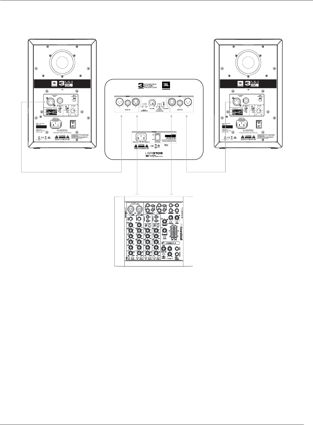
LSR310S POWERED STUDIO SUBWOOFER CONNECTIONS
The left and right outputs of the signal source should be connected directly to the LEFT IN and RIGHT
IN connectors of the subwoofer. The LEFT OUT and RIGHT OUT connectors of the subwoofer should be
connected to the inputs of the left and right speakers respectively.
POWER CONNECTIONS
Connect the included IEC power cable to each 3 Series speaker and subwoofer. The 3 Series speakers
incorporate a universal power supply, allowing them to be used domestically and internationally. The ground
terminal of the IEC plug is required by wiring codes and regulations and must always be connected to the
electrical installation safety ground.
MAKING SOUND
1. Ensure the VOLUME control on each 3 Series speaker/subwoofer is set to the full counter-clockwise
(minimum) position.
2. Power on the connected audio equipment (mixing console, computer audio interface, preamp, etc.).
3. Set the POWER switch on each 3 Series speaker/subwoofer to the ON position. After a short delay, the
POWER LED on the front of each speaker will illuminate and the speakers will be ready to reproduce
audio signals.
4. Play full range program material from the source with ample low frequency content so that you can
properly judge the bass response of the system. Now slowly advance the volume control of the source
device until its nominal operating level is achieved.
5. Slowly increase the VOLUME control on each 3 Series Studio Monitor until the desired listening level is
achieved and all speakers are matched in output level to achieve a balanced image.
6. Balance the subwoofer in the system using the rear panel VOLUME control. Additional balance of bass
can be achieved by changing the placement of the subwoofer in the room.
10
1
3
4
8
5
6
7
Front View Back View
2
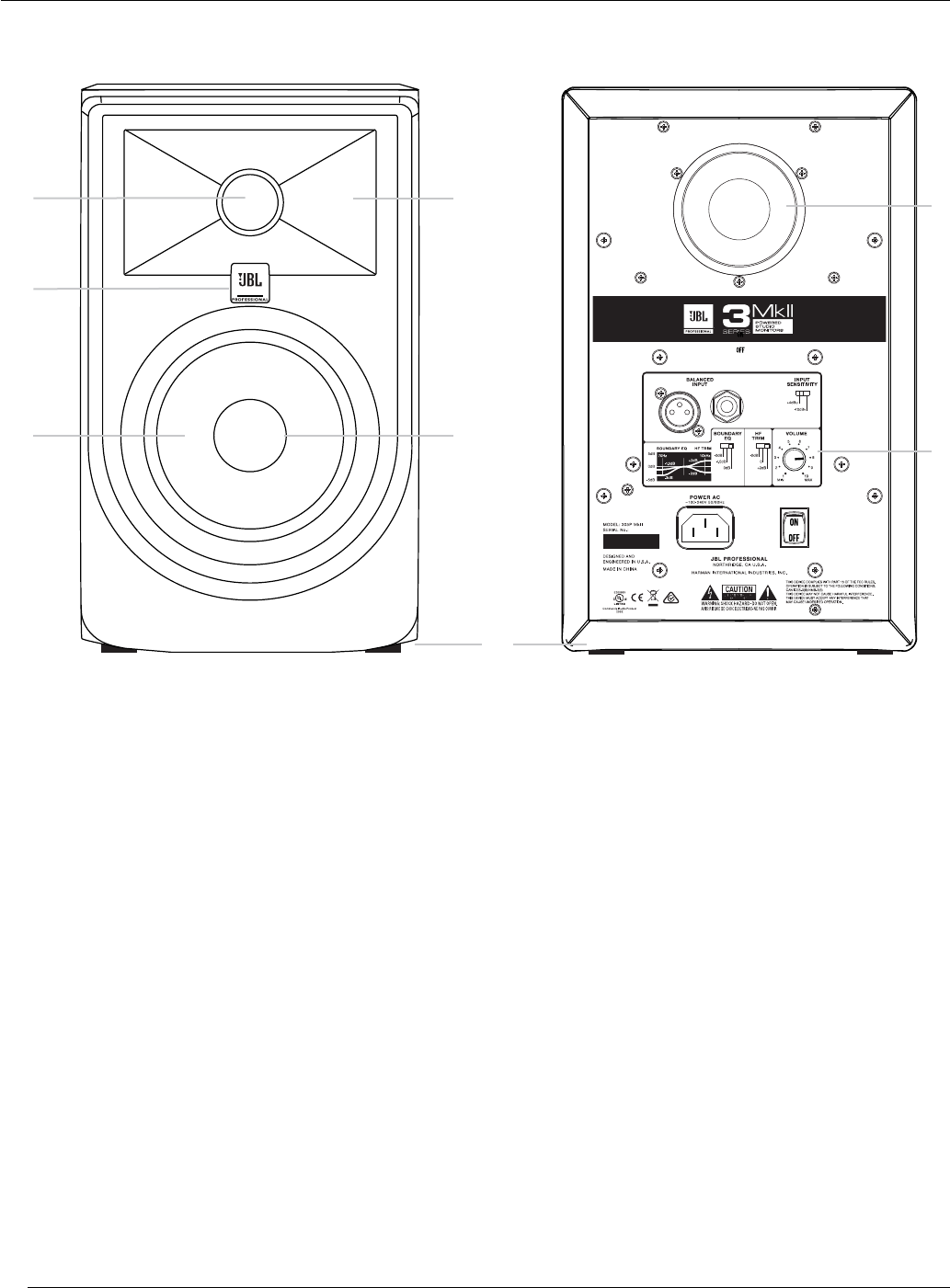
FEATURES
1. HIGH FREQUENCY TRANSDUCER (TWEETER) – This transducer reproduces high frequency signals.
2. WAVEGUIDE – The specially designed JBL Image Control Waveguide enhances imaging and optimizes
the blend of direct and reected sound in the room, ensuring neutral sound at the mix position.
3. POWER LED – This LED illuminates when power is connected and the POWER switch is set to ON. Note
that after turning the power switch to the ON setting, there is a short delay prior to illumination of the LED.
4. LOW FREQUENCY TRANSDUCER (WOOFER) – This transducer reproduces low frequencies.
5. DUST DOME – Protects the inner circuit of the woofer. This self-repairing dust dome is resistant to dents
caused by ngers and objects.
6. LOW FREQUENCY PORT – The patented Slip Stream™ Port works in conjunction with the low frequency
transducer to provide accurate low frequency performance.
7. INPUT PANEL – This panel includes the power connector, input connectors, and user controls.
8. PADS – Four self-adhering pads are supplied with each studio monitor.
Section 4: 305P, 306P, and 308P MkII Powered Studio Monitors
11
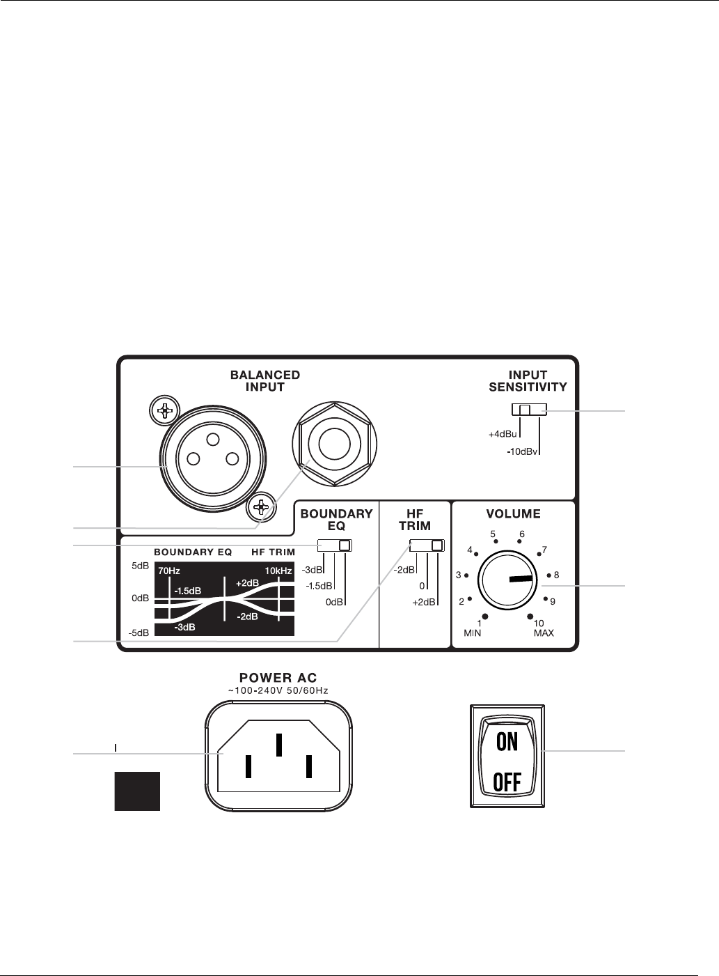
INPUT PANEL
9. XLR INPUT – Connect professional equipment to this connector using a balanced XLR plug.
10. 6MM (¼") INPUT – Connect professional equipment to this connector using a 6mm (¼") balanced plug.
Connect consumer equipment to this connector using a 6mm (¼") unbalanced plug.
11. INPUT SENSITIVITY SWITCH – Set this switch to +4dBu to protect from overload when connecting to
professional equipment and sources with high output level capabilities. Set this switch to -10dBV when
connecting to lower-level consumer-grade audio equipment or to the LSR310S subwoofer.
12. BOUNDARY EQ SWITCH – This switch is used to compensate for low frequency anomalies that may
occur when speakers are placed on a work surface or in close proximity to walls. Settings include 0dB,
-1.5dB, and -3dB. Select the setting that provides the most natural bass response for the application.
13. HIGH FREQUENCY TRIM SWITCH – This switch allows boost or attenuation of high frequency output by
2dB. Select the setting that provides the desired high frequency response for the application.
14. VOLUME CONTROL – Use this control to set the maximum listening level.
15. POWER RECEPTACLE – Connect the included power cord to this receptacle.
16. POWER SWITCH – This switch turns the speaker on or off.
9
12
10
11
14
16
15
13
AUDIO CONNECTIONS
Connect signal sources to either the XLR or 6mm (¼") INPUT connectors. Connect only a single signal source
to the speaker using either the XLR INPUT connector, OR the 6mm (¼") TRS INPUT connector. Do not connect
signal sources to both input connectors simultaneously.

12
AUTO STANDBY FEATURE
3 Series MkII models bearing the CE mark include an automatic low-power standby feature that reduces power
consumption when no signal is detected for a period of twenty minutes. When used in professional applications
in which auto-low power standby is not desirable, the feature can be disabled. The feature is enabled by default.
Use the following procedure to disable the auto-low power standby mode:
1. Power speaker OFF.
2. Set BOUNDARY EQ to the “0dB” setting.
3. Set HF Trim to “+2dB” setting.
4. Set the VOLUME control to “1” (full counter-clockwise setting).
5. Power the speaker ON.
6. Within a period of 5 seconds following power-ON:
• Set BOUNDARY EQ to the “-3dB” setting and...
• Set the HF TRIM switch to the “-2dB” setting.
7. The front panel LED will ash for 5 seconds indicating the low-power auto-standby mode has been
disabled and will remain disabled upon subsequent power cycles.
Use the following procedure to enable the auto-standby mode:
1. Power the speaker OFF.
2. Set BOUNDARY EQ to the “-3dB” setting.
3. Set HF TRIM to the “-2dB” setting.
4. Set the VOLUME control to “1” (full counter-clockwise setting).
5. Power the speaker ON.
6. Within a period of 5 seconds following power-ON:
• Set the BOUNDARY EQ switch to the “0dB” setting and...
• Set the HF TRIM switch to the “+2dB” setting.
7. The front panel LED will ash for 5 seconds indicating the low-power auto-standby mode has been
enables and will remain enabled upon subsequent power cycles.
13
2
5
1
4
1
3 3
Front View
Bottom View
Back View
FEATURES
1. LOW FREQUENCY TRANSDUCER (WOOFER) – This transducer reproduces low frequency signals.
2. POWER LED – This LED illuminates when power is connected and the POWER switch is set to ON.
3. FEET – These feet elevate the subwoofer to prevent acoustic coupling with the oor.
4. LOW FREQUENCY PORT – This port works in conjunction with the low frequency transducer to provide
accurate low frequency performance.
5. INPUT PANEL – This panel includes the power connector, input connectors, and user controls.
Section 5: LSR310S Powered Studio Subwoofer
14
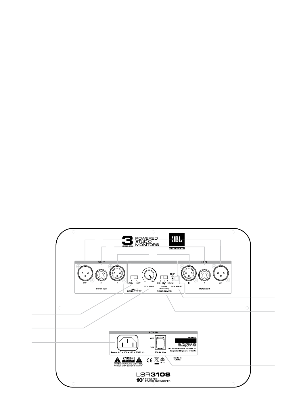
INPUT PANEL
6. RIGHT AND LEFT XLR INPUTS – Connect professional equipment to these connectors using balanced
XLR plugs.
7. RIGHT AND LEFT 6MM (¼") – Connect professional equipment to these connectors using 6mm (¼")
balanced plugs. Connect consumer equipment to these connectors using 6mm (¼") unbalanced plugs.
8. RIGHT AND LEFT XLR OUTPUTS – Connect these outputs to the 3 Series MkII speakers or other
powered speakers or power amplier in your monitoring system.
9. INPUT SENSITIVITY SWITCH – Set this switch to the +4dBu setting when connecting professional
equipment and sources with very high output. Set this switch to -10dBV when connecting to lower-level
consumer-grade audio equipment.
NOTE: When the LSR310S is used in a system with 3 Series MkII speakers, set the INPUT SENSITIVITY
switch on the 305P, 306P, or 308P MkII to the -10dBV setting regardless of the LSR310S input sensitivity
switch setting.
10. VOLUME CONTROL – Use this control to balance the volume of the subwoofer with the volume of the
speakers in the system.
11. CROSSOVER FREQUENCY – This crossover provides three settings: 80Hz, XLF, and External. The 80Hz
setting is recommended for use with studio monitors, including the 305P, 306P, or 308P MkII. The External
setting allows use of an outboard active crossover. Select the XLF (Extended Low Frequency) setting to
activate a circuit that emulates the bass tuning commonly applied to club playback systems.
12. POLARITY – Enables optional 180 degree polarity reversal of the subwoofer output to optimize the blend
of the subwoofer with the main speakers according to relative speaker and listening positions. Select the
setting that produces the greatest amount of bass when heard at the listening position.
13. POWER RECEPTACLE – Connect the included power cord to this receptacle.
14. POWER SWITCH – Set this switch to the ON position to operate the subwoofer. Set this switch to the
OFF position when the subwoofer is not in use.
13
9
12
11
14
6
8
7
10

15
AUDIO CONNECTIONS
Connect signal sources to either the XLR or 6mm (¼") INPUT connectors. Connect a single signal source to
the speaker using either the XLR INPUT connectors, OR the 6mm (¼") TRS INPUT connectors. Do not connect
multiple signal sources to the XLR and 6mm (¼") input connectors simultaneously.
If the LSR310S subwoofer is being used to reproduce the .1 LFE channel in a surround sound system, connect
the .1 LFE signal to either the LEFT or RIGHT input of the subwoofer.
SETTING THE SUBWOOFER LEVEL
When the LSR310S subwoofer is used in a system with 3 Series MkII Studio Monitors, the ideal balance is
achieved when the position of the subwoofer VOLUME control is set to the same position as the main speaker
VOLUME controls. However, note that the placement of the speakers in the room can affect the amount of bass
heard at the listening position. If more or less subwoofer volume is desired, use the subwoofer VOLUME control
to achieve the optimum balance for the application and your preference.
PLACEMENT AND POLARITY SETTING
Because the human ear cannot easily recognize the origin of low frequency sounds (the sounds are said to
be “non-directional”), subwoofer placement is not nearly as critical as main channel speaker positioning.
The LSR310S is designed to be placed directly on the oor and not elevated or mounted in any way. Set the
POLARITY switch to the setting that yields a stronger perceived bass response at the listening position.
In a stereo system, the subwoofer should optimally be placed between the two main speakers. In a surround
sound system, the subwoofer should be placed between the center and left channel speakers or the center
and right channel speakers. Precise central placement is not necessary. Centered positioning in the room can
sometimes cause unwanted cancellation of low frequency content, so it is recommended that the subwoofer be
placed slightly off-center and not at the midpoint between the left and right walls.

16
CROSSOVER SETTINGS AND BASS MANAGEMENT
“Bass management” is a term that refers to the practice of using a subwoofer to reproduce the bass frequencies
of the main channels. Because of the physiology of the human ear, low frequencies are largely non-directional.
Given an adequate listening distance, we can’t easily tell where bass signals are coming from. Thus, it makes
little or no difference to the listening experience whether the bass component in a sound comes from the
originating speaker—which may be off to your left or right, or even behind you—or from a dedicated subwoofer
which is better equipped and better positioned in the room to reproduce low frequencies. For that reason, you
may want to use an LSR310S subwoofer to reproduce all the bass frequencies in the system.
When using an LSR310S subwoofer in the system, bass management is accomplished by simply routing the
left and right mix channels to the LSR310S inputs and then from the LSR310S outputs to the left and right
speakers. The frequency at which the subwoofer divides signals to the sub and the left and right speakers can
be set using the CROSSOVER FREQUENCY selector switch on the input panel of the LSR310S.
The LSR310S offers three crossover settings:
• 80Hz
The 80Hz setting is recommended when the goal is a full range reference monitor system that accurately
portrays content below the cut-off frequency of the main speakers. The 80Hz setting provides a smooth
transition between the subwoofer and main speakers without audible localization of bass, creating the
perception of a full range system with no subwoofer.
• XLF
A trend in music production is the requirement for enhanced low frequency response in the control
room. Artists and producers involved in the production of dance music appreciate the ability to audition
their work as it might sound when played on a system with enhanced low frequency tuning, commonly
employed in dance clubs.
A JBL rst, the LSR310S includes a special XLF (Extended Low Frequency) setting that emulates the
response curve applied to a club playback system. When the XLF crossover setting is selected, a 120Hz
high-pass lter is engaged in conjunction with a 10dB boost at 60Hz with a bandwidth of 0.5 octaves.
Using this setting, the bass output more than doubles and the character of the low frequency energy
approximates that of a club system.
Continuous low frequency energy with very high peak SPL is made possible by JBL’s new long excursion
low frequency driver, working in concert with JBL’s patented Slip Stream™ Port, and powered by a 200
watt Class-D amplier. A protective circuit allows the LSR310S to continuously produce low frequencies at
high output levels without failure. In situations where positioning will allow, an additional 6dB of output can
be achieved by positioning the LSR310S subwoofer adjacent to a wall or at the intersection of two walls.
• External
Select this setting when connecting the subwoofer to an external active crossover. Note that when the
External option is selected, the XLR LEFT and RIGHT OUT connectors are disabled.
SURROUND SOUND SYSTEMS AND LFE
The LSR310S subwoofer can be used to reproduce the LFE (Low Frequency Effects) or .1 channel in a surround
sound system. In lm production applications, the LFE channel contains low frequency effects, such as the
sounds of explosions and other sounds with a strong low frequency component. In music applications, the LFE
channel usually contains low frequency instruments such as bass, bass drum, and synthesizer elements.
17
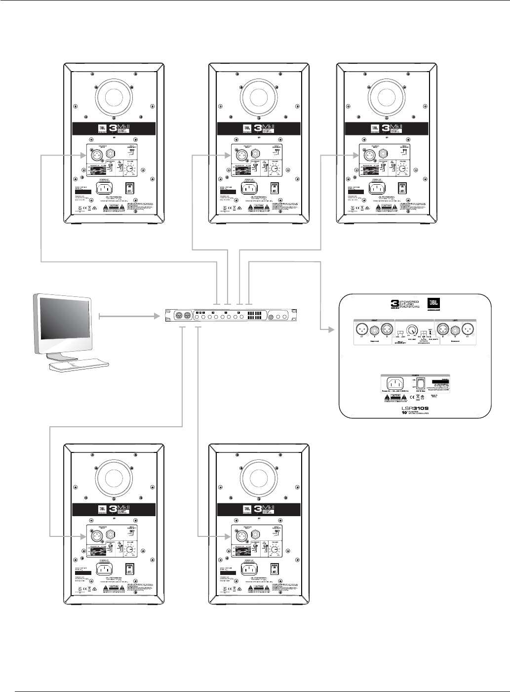
TWO CHANNEL SYSTEMS
LEFT SPEAKER
(REAR PANEL)
RIGHT SPEAKER
(REAR PANEL)
SUBWOOFER
(REAR PANEL)
MIXER
Section 6: System Connections
18
SURROUND SOUND SYSTEMS
SUBWOOFER
(REAR PANEL)
COMPUTER
AUDIO SYSTEM
LEFT SPEAKER
(REAR PANEL)
RIGHT SPEAKER
(REAR PANEL)
CENTER SPEAKER
(REAR PANEL)
COMPUTER
AUDIO INTERFACE
LEFT
SURROUND SPEAKER
(REAR PANEL)
RIGHT
SURROUND SPEAKER
(REAR PANEL)

19
Issue: There is no sound from the speakers.
• Conrm the power cable is connected to the speaker and the POWER switch is set to the ON position.
• Make sure the POWER LED is illuminated on the front of the speaker.
• Make sure a signal source is connected to the speaker and that it is producing sound.
• Make sure the speaker's VOLUME control is not set to the full counter-clockwise (minimum) position.
Issue: The signal is distorted.
• Verify the speaker's INPUT SENSITIVITY switch is set to +4dBu. If the distortion persists, even with the
speaker's VOLUME control set low, inspect the gain stages throughout the system to determine which circuit
in the signal path is being overdriven.
Issue: The signal level is low.
• Ensure the speaker's VOLUME control is turned up.
• Try setting the speaker's INPUT SENSITIVITY switch to -10dBV.
Issue: The speaker or subwoofer sounds boomy.
• If using the 305P, 306P, or 308P MkII Studio Monitors without the LSR310S Studio Subwoofer, try lifting
one of the speakers off of the supporting surface to see if the boominess is lessened. If it is, the speaker is
likely resonating through the surface it is sitting upon. Try isolating the speakers using a third-party speaker
isolation product. Alternatively, try engaging the BOUNDERY EQ on the speakers. Try both the -1.5dB and
-3dB settings to determine which setting provides the most natural bass response.
• If using the LSR310S Studio Subwoofer, try locating the subwoofer in a different position in the room, away
from corners. Try placing the subwoofer at the listening position and walk around the room while listening
to the system. When you nd a practical position that provides the desired bass response, try placing the
subwoofer at that location.
If the above measures do not correct the problem, please contact JBL Professional Customer Service for
assistance.
Section 7: Troubleshooting

20
305P 306P 308P LSR310S
Frequency Range
(-10dBV):43Hz – 24kHz 39Hz – 24kHz 37Hz – 24kHz 27Hz
Crossover: 1725Hz 4th Order Acoustic
Linkwitz-Riley
1425Hz 4th Order Acoustic
Linkwitz-Riley
1800Hz 4th Order Acoustic
Linkwitz-Riley - - -
Maximum Continuous SPL: 94 dB* 98 dB* 102 dB* 105 dB**
Maximum Peak SPL: 108dB*110dB* 112dB*113dB**
Maximum Peak Input Level
(-10dBV / +4dBu): +6dBV / +20.3dBu+6dBV / +20.3dBu +6dBV / +20.3dBu+6dBV / +20.3dBu
Input Connectors: 1 x XLR, 1 x TRS Balanced 1 x XLR, 1 x TRS Balanced 1 x XLR, 1 x TRS Balanced 2 x XLR, 2 x TRS Balanced
Input Sensitivity:
(-10dBV input) 92dB / 1m 92dB / 1m 92dB / 1m 92dB / 1m
HF Driver Size: 25mm (1") 25mm (1") 25mm (1") - - -
LF Driver Size: 127mm (5") 165mm (6.5") 203mm (8") 250mm (10")
HF Driver Power Amp: 41W Class-D 56W Class-D 56W Class-D - - -
LF Driver Power Amp: 41W Class-D 56W Class-D 56W Class-D 200W Class-D
HF Trim Control: HF Shelf @ 4.4kHz: +2dB,
0dB, -2dB
HF Shelf @ 4.4kHz: +2dB,
0dB, -2dB
HF Shelf @ 4.4kHz: +2dB,
0dB, -2dB - - -
Boundary EQ Control: LF Shelf @ 50Hz: -3dB,
-1.5dB, 0dB
LF Shelf @ 50Hz: -3dB,
-1.5dB, 0dB
LF Shelf @ 50Hz: -3dB,
-1.5dB, 0dB - - -
AC Input Voltage: 100 – 240 VAC (±10%),
50/60Hz
100 – 240 VAC (±10%),
50/60Hz
100 – 240 VAC (±10%),
50/60Hz 100-240 VAC +/- 10% 50/60Hz
Power Consumption: 127W Max 185W Max 224W Max 500W Max
Enclosure Construction: 15mm MDF 15mm MDF 15mm MDF 18mm (3/4 in) MDF
Enclosure Finish: Matte Black PVC Matte Black PVC Matte Black PVC Matte Black PVC
Baffle Construction: Injection-Molded
Structural ABS
Injection-Molded
Structural ABS
Injection-Molded
Structural ABS - - -
Cabinet Dimensions
(H x W x D***):
298 x 185 x 231mm
(11.7" x 7.3" x 9.1")
361 x 224 x 282mm
(14.2" x 8.8" x 11.1")
419 x 254 x 308mm
(16.5" x 10" x 12.1")
448 x 381 x 398mm
(17.65" x 15.0" x 15.65")
Display Carton
(H x W x D):
354 x 244 x 299mm
(13.9" x 9.6" x 11.8")
408 x 285 x 328mm
(16.1" x 11.2" x 12.9")
473 x 312 x 358mm
(18.6" x 12.3" x 14")
505 x 466 x 476mm
(19.9" x 18.3" x 18.7")
Shipping Carton
(H x W x D):
373 x 260 x 315mm
(14.7" x 10.2" x 12.4")
418 x 292 x 338mm
(16.5" x 11.5" x 13.3")
491 x 326 x 372mm
(19.3" x 12.8" x 14.6")
520 x 478 x 488mm
(20.5" x 18.8" x 19.2")
Net Weight: 4.73 kg (10.43 lbs) 6.1 kg (13.42 lbs) 8.1 kg (17.87 lbs) 15.6 kg (34.3 lbs)
Shipping Weight: 5.72 kg (12.61 lbs) 7.25 kg (15.95 lbs) 9.4 kg (20.73 lbs) 19.1 kg (42 lbs)
* Full bandwidth pink noise, measured C-Weighted
** Measured in half space
*** Depth measured without power cord and audio connectors
(typical power cord = 2 inches, typical XLR connector = 2.5 inches)
Section 8: Specications

21
MAILING ADDRESS:
JBL Professional
8500 Balboa Blvd.
Northridge, CA 91329
SHIPPING ADDRESS:
Please contact JBL Professional Customer Service for shipping information prior to repairs.
CUSTOMER SERVICE:
Monday through Friday
8:00am – 5:00pm
Pacic Coast Time in the U.S.A.
(800) 8JBLPRO (800.852.5776)
www.jblproservice.com
PRODUCT REGISTRATION:
Register your product online at www.jblpro.com/registration
ON THE WORLD WIDE WEB:
www.jblpro.com
PROFESSIONAL CONTACTS, OUTSIDE THE USA:
Contact the JBL Professional Distributor in your area. A complete list of JBL Professional international distributors
is provided at our U.S.A. website: www.jblpro.com
EN DEHORS DES ETATS-UNIS:
Contacter votre Distributeur JBL Professional. Une liste complète de nos distributeurs internationaux est disponible
sur le site web—www.jblpro.com
INTERNATIONAL:
Wenden Sie sich an Ihre örtliche JBL Professional Vertretung. Eine vollständige Liste der internationalen
JBL-Vertretungen nden Sie auf unserer Website unter www.jblpro.com
FUERA DE LOS ESTADOS UNIDOS:
Comuníquese con el distribuidor de JBL Professional de su zona. En nuestro sitio web, www.jblpro.com,
encontrará una lista completa de los distribuidores de JBL International.
Section 9: JBL Service Contact Information

22
Section 10: Product Warranty Information
The JBL Limited Warranty on professional loudspeaker products (except for enclosures) remains in effect for
ve years from the date of the rst consumer purchase. JBL ampliers are warranted for three years from the
date of original purchase. Enclosures and all other JBL products are warranted for two years from the date of
original purchase.
WHO IS PROTECTED BY THIS WARRANTY?
Your JBL Warranty protects the original owner and all subsequent owners so long as: A.) Your JBL product
has been purchased in the Continental United States, Hawaii or Alaska. (This Warranty does not apply to JBL
products purchased elsewhere except for purchases by military outlets. Other purchasers should contact the
local JBL distributor for warranty information.); and B.) The original dated bill of sale is presented whenever
warranty service is required.
WHAT DOES THE JBL WARRANTY COVER?
Except as specied below, your JBL Warranty covers all defects in material and workmanship. The following
are not covered: Damage caused by accident, misuse, abuse, product modication or neglect; damage
occurring during shipment; damage resulting from failure to follow instructions contained in your Instruction
Manual; damage resulting from the performance of repairs by someone not authorized by JBL; claims based
upon any misrepresentations by the seller; any JBL product on which the serial number has been defaced,
modied
or removed.
WHO PAYS FOR WHAT?
JBL will pay all labor and material expenses for all repairs covered by this warranty. Please be sure to save
the original shipping cartons because a charge will be made if replacement cartons are requested. Payment of
shipping charges is discussed in the next section of this warranty.
HOW TO OBTAIN WARRANTY PERFORMANCE
If your JBL product ever needs service, write or telephone us at JBL Incorporated (Attn: Customer Service
Department), 8500 Balboa Boulevard, PO. Box 2200, Northridge, California 91329 (818/893-8411). We may
direct you to an authorized JBL Service Agency or ask you to send your unit to the factory for repair. Either way,
you’ll need to present the original bill of sale to establish the date of purchase. Please do not ship your JBL
product to the factory without prior authorization. If transportation of your JBL product presents any unusual
difculties, please advise us and we may make special arrangements with you. Otherwise, you are responsible
for transporting your product for repair or arranging for its transportation and for payment of any initial shipping
charges. However, we will pay the return shipping charges if repairs are covered by the warranty.
LIMITATION OF IMPLIED WARRANTIES
ALL IMPLIED WARRANTIES, INCLUDING WARRANTIES OF MERCHANTABILITY AND FITNESS FOR
PARTICULAR PURPOSE, ARE LIMITED IN DURATION TO THE LENGTH OF THIS WARRANTY.
EXCLUSION OF CERTAIN DAMAGES
JBL’S LIABILITY IS LIMITED TO THE REPAIR OR REPLACEMENT, AT OUR OPTION, OF ANY DEFECTIVE
PRODUCT AND SHALL NOT INCLUDE INCIDENTAL OR CONSEQUENTIAL DAMAGES OF ANY KIND. SOME
STATES DO NOT ALLOW LIMITATIONS ON HOW LONG AN IMPLIED WARRANTY LASTS AND/OR DO NOT
ALLOW THE EXCLUSION OF INCIDENTAL OR CONSEQUENTIAL DAMAGES, SO THE ABOVE LIMITATIONS
AND EXCLUSIONS MAY NOT APPLY TO YOU. THIS WARRANTY GIVES YOU SPECIFIC LEGAL RIGHTS, AND
YOU MAY ALSO HAVE OTHER RIGHTS, WHICH VARY, FROM STATE TO STATE.
JBL Professional
8500 Balboa Boulevard
Northridge, CA 91329 USA
Visit us online at www.jblpro.com

Part Number:
5096517-00-C
