JBL My TI Innovator™ Technology Guidebook Innovator EN
User Manual: JBL TI-Innovator™ Technology Guidebook TI-Innovator™ System Guidebooks
Open the PDF directly: View PDF ![]() .
.
Page Count: 389 [warning: Documents this large are best viewed by clicking the View PDF Link!]
- Important Information
- TI‑Innovator™ Technology Getting Started Guide
- TI-Innovator™ Technology Overview
- What's in the Box
- Connecting TI‑Innovator™ Hub
- Updating the Hub Software
- Installing the Hub App on TI CE Graphing Calculator
- Hub Programming on TI CE Graphing Calculator
- Hub Programming on TI‑Nspire™ CX Technology
- TI‑Innovator™ I/O Modules
- TI‑Innovator™ Breadboard Pack
- Using an Auxiliary Power Source
- Troubleshooting
- General Precautions
- TI-Innovator™ Hub Commands version 1.2
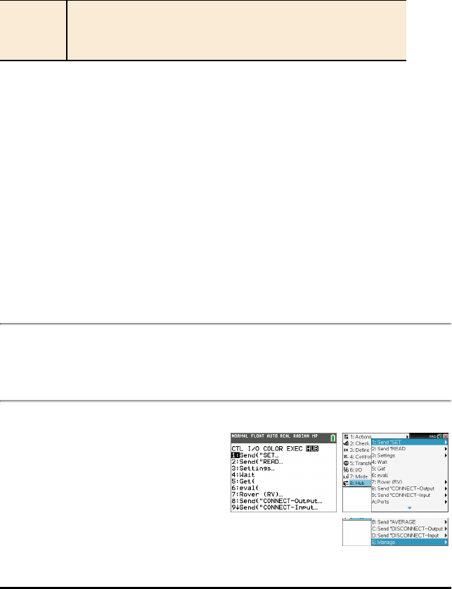
- HUB Menus
- Send(SET...
- Send(READ...
- Settings...
- Wait
- Get(
- eval(
- Rover (RV)...
- Send(CONNECT-Output...
- Send(CONNECT-Input...
- Ports...
- Send(RANGE...
- Send(AVERAGE...
- Send(DISCONNECT-Output...
- Send(DISCONNECT-INPUT...
- MANAGE
- Additional Supported Commands Not Found in the Hub Menu
- SET
- LIGHT [TO] ON/OFF
- COLOR [TO] r g b [[BLINK|TOGGLE] frequency] [[TIME] seconds]
- COLOR.RED [TO] r [[BLINK|TOGGLE] frequency] [[TIME] seconds]
- COLOR.GREEN [TO] g [[BLINK|TOGGLE] frequency] [[TIME] seconds]
- COLOR.BLUE [TO] b [[BLINK|TOGGLE] frequency] [[TIME] seconds]
- SOUND [TO] frequency [[TIME] seconds]
- SOUND OFF/0
- LED i [TO] ON/OFF
- LED i [TO] 0-255
- SPEAKER i [TO] frequency [[TIME] seconds]
- BUZZER i [TO] ON [TIME seconds]
- BUZZER i [TO] OFF
- RELAY i [TO] ON/OFF
- SERVO i [TO] position
- SERVO i [TO] STOP
- SERVO i [TO] ZERO
- SERVO i [TO] [CW/CCW] speed [[TIME] seconds]
- DCMOTOR i [TO] frequency [duty [[TIME] seconds]]
- DCMOTOR i OFF
- VIB.MOTOR i [TO] PWM
- VIB.MOTOR i [TO] OFF|STOP
- VIB.MOTOR i [TO] 0-255/UP/DOWN/ON/OFF [[BLINK|TOGGLE] freq] [[TIME] seconds]
- SQUAREWAVE i [TO] frequency [duty [[TIME] seconds]]
- SQUAREWAVE i OFF
- RGB i [TO] r g b [[BLINK|TOGGLE] frequency] [[TIME] seconds]
- RED i [TO] ON/OFF/UP/DOWN/value [[BLINK|TOGGLE] frequency] [[TIME] seconds]
- GREEN i [TO] ON/OFF/UP/DOWN/value [[BLINK|TOGGLE] frequency] [[TIME] seconds]
- BLUE i [TO] ON/OFF/UP/DOWN/value [[BLINK|TOGGLE] frequency] [[TIME] seconds]
- ANALOG.OUT i [TO]
- ANALOG.OUT i OFF|STOP
- DIGITAL.OUT i [TO] ON/OFF/HIGH/LOW/[[BLINK|TOGGLE] frequency] [[TIME] seconds]
- DIGITAL.OUT i [TO] OUTPUT/CLOCK
- DIGITAL.IN i [TO] INPUT/PULLUP/PULLDOWN
- AVERAGING [TO] n
- READ
- BRIGHTNESS
- BRIGHTNESS AVERAGE
- BRIGHTNESS RANGE
- DHT i
- DHT i TEMPERATURE
- DHT i HUMIDITY
- RANGER i
- LOUDNESS i
- LOUDNESS i AVERAGE
- LOUDNESS i RANGE
- LIGHTLEVEL i
- LIGHTLEVEL i AVERAGE
- LIGHTLEVEL i RANGE
- TEMPERATURE i
- TEMPERATURE i AVERAGE
- TEMPERATURE i CALIBRATION
- SWITCH i
- BUTTON i
- MOTION i
- POTENTIOMETER i
- POTENTIOMETER i AVERAGE
- POTENTIOMETER i RANGE
- MOISTURE i
- MOISTURE i AVERAGE
- MOISTURE i RANGE
- THERMISTOR i
- THERMISTOR i AVERAGE
- THERMISTOR i CALIBRATION
- ANALOG.IN i
- ANALOG.IN i AVERAGE
- ANALOG.IN i RANGE
- ANALOG.OUT i
- DIGITAL.IN i
- AVERAGING
- Settings
- Wait
- Get(
- eval(
- ROVER (RV) Menu
- Drive RV...
- READ RV Sensors...
- RV Settings...
- Read RV Path…
- Reading WAYPOINT and PATH
- RV Position and Path
- RV.WAYPOINT.XYTHDRN
- RV.WAYPOINT.PREV
- RV.WAYPOINT.CMDNUM
- RV.PATHLIST.X
- RV.PATHLIST.Y
- RV.PATHLIST.TIME
- RV.PATHLIST.HEADING
- RV.PATHLIST.DISTANCE
- RV.PATHLIST.REVS
- RV.PATHLIST.CMDNUM
- RV.WAYPOINT.X
- RV.WAYPOINT.Y
- RV.WAYPOINT.TIME
- RV.WAYPOINT.HEADING
- RV.WAYPOINT.DISTANCE
- RV.WAYPOINT.REVS
- RV Color…
- RV Setup…
- RV Control…
- Send CONNECT RV
- Send DISCONNECT RV
- CONNECT - Output
- LIGHT
- COLOR
- SOUND
- LED i [TO] OUT n/BB n
- SPEAKER i [TO] OUT n/BB n
- BUZZER i [TO] OUT n/BB n
- RELAY i [TO] OUT n/BB n
- SERVO i [TO] OUT n
- SERVO.CONTINUOUS i [TO] BB 6
- DCMOTOR i [TO] OUT n/BB n
- RGB i / COLOR [TO] BB r BB g BB b
- SQUAREWAVE i [TO] OUT n/BB n
- ANALOG.OUT i [TO] OUT i/BB i
- DIGITAL.OUT i [TO] OUT n/BB n [[AS] OUTPUT]
- CONNECT-Input
- BRIGHTNESS
- DHT i [TO] IN n
- RANGER i [TO] IN n
- LOUDNESS i [TO] IN n
- LIGHTLEVEL i [TO] IN n/BB n
- TEMPERATURE i [TO] IN n/BB n
- SWITCH i [TO] IN n/BB n
- BUTTON i [TO] IN n/BB n
- MOTION i [TO] IN n/BB n
- POTENTIOMETER i [TO] IN n/BB n
- MOISTURE i [TO] IN n/BB n
- THERMISTOR i [TO] IN n/BB n
- ANALOG.IN i [TO] IN n/BB n
- DIGITAL.IN i [TO] IN n/BB n [[AS] INPUT|PULLUP|PULLDOWN]
- Ports
- RANGE
- AVERAGE
- DISCONNECT-Output
- DISCONNECT-Input
- MANAGE
- BEGIN
- ISTI
- WHO
- WHAT
- HELP
- VERSION
- ABOUT
- Additional Supported Commands
- Additional SET Commands
- FORMAT ERROR STRING/NUMBER
- FORMAT ERROR NOTE/QUIET
- FLOW [TO] ON/OFF
- OUT1/2/3 [TO]
- Additional READ Commands
- BUZZER i
- COLOR
- COLOR.RED
- COLOR.GREEN
- COLOR.BLUE
- DCMOTOR i
- DIGITAL.OUT i
- FORMAT
- FLOW
- IN1/IN2/IN3
- LAST ERROR
- LED i
- LIGHT
- OUT1/2/3
- PWR
- RELAY i
- RESOLUTION
- RGB i
- RED i
- GREEN i
- BLUE i
- SERVO i
- SERVO i CALIBRATION
- SOUND
- SPEAKER i
- SQUAREWAVE i
- Additional AVERAGE Commands
- PERIOD n
- Additional CALIBRATION Commands
- CALIBRATE
- SERVO i / SERVO.CONTINUOUS i
- TEMPERATURE i C1 C2 C3 R1
- THERMISTOR i C1 C2 C3 R1
- TI-Innovator™ Hub Data Sheets
- TI-Innovator™ Hub Data Sheet
- TI-Innovator™ Hub Ports and Breadboard Usable Pins
- TI-Innovator™ Hub On-Board Component Data Sheets
- On-Board RGB LED Data Sheet
- On-Board Red LED Data Sheet
- On-Board Speaker Data Sheet
- On-Board Light Brightness Sensor Data Sheet
- On-Board - Auxiliary Power Indicator Data Sheet
- On-Board Green LED - Power Indicator Data Sheet
- On-Board Red LED - Error Indicator Data Sheet
- USB Mini A to Mini B Cable Data Sheet
- USB Standard A to Mini B Cable Data Sheet
- USB Standard A to Micro B Cable Data Sheet
- TI Wall Charger Data Sheet
- External Battery Data Sheet
- TI‑Innovator™ Rover Setup Guide
- TI-Innovator™ Rover Commands version 1.2
- Prerequisite: Use the Send Connect RV Command First
- TI-Innovator™ Rover Menu
- Drive RV...
- READ RV Sensors...
- RV Settings...
- Read RV Path…
- Reading WAYPOINT and PATH
- RV Position and Path
- RV.WAYPOINT.XYTHDRN
- RV.WAYPOINT.PREV
- RV.WAYPOINT.CMDNUM
- RV.PATHLIST.X
- RV.PATHLIST.Y
- RV.PATHLIST.TIME
- RV.PATHLIST.HEADING
- RV.PATHLIST.DISTANCE
- RV.PATHLIST.REVS
- RV.PATHLIST.CMDNUM
- RV.WAYPOINT.X
- RV.WAYPOINT.Y
- RV.WAYPOINT.TIME
- RV.WAYPOINT.HEADING
- RV.WAYPOINT.DISTANCE
- RV.WAYPOINT.REVS
- RV Color…
- RV Setup…
- RV Control…
- Send CONNECT RV
- Send DISCONNECT RV
- TI-Innovator™ Rover – Programmable Component Data Sheets
- TI-Innovator™ Rover
- TI-Innovator™ Rover On-Board Rotary Encoders Data Sheet
- TI-Innovator™ Rover On-Board Gyroscope Data Sheet
- TI-Innovator™ Rover On-Board Ultrasonic Ranger Data Sheet
- TI-Innovator™ Rover On-Board Color Sensor Data Sheet
- On-Board Light Brightness Sensor Data Sheet
- TI-Innovator™ Rover On-Board Electric Motors Data Sheet
- TI-Innovator™ Rover On-Board RGB (Red-Green-Blue) LED Data Sheet
- On-Board Speaker Data Sheet
- I/O Modules Data Sheets
- TI-Innovator™ Breadboard Data Sheets
- Breadboard Components and Usable Pins
- Environmental Sensors
- Thermistor Data Sheet
- TI Analog Temperature Sensor Data Sheet
- Visible Light Sensor Data Sheet
- LEDs and Displays
- Green LED Data Sheet
- RGB (Red-Green-Blue) LED Data Sheet
- Red LED Data Sheet
- Diode Data Sheet
- 7-segment Display Data Sheet
- Infrared Receiver Data Sheet
- Infrared Transmitter Data Sheet
- Motors
- Small DC Motor Data Sheet
- Power and Signal Control
- SPDT Slide Switch Data Sheet
- 8 Position DIP Switch Data Sheet
- 8 100 Ohm Resistor SIP Package Data Sheet
- TTL Power MOSFET Data Sheet
- Passive Components
- Accessories
- Breadboard Data Sheet
- Capacitors
- Resistors
- Frequently Asked Questions
- Product Configuration Information
- What are the TI-Innovator™ configurations that are available for sale?
- What is included with the TI-Innovator™ Rover?
- What is included in the TI-Innovator™ Hub Kit?
- What is included in the TI-Innovator™ I/O Module Pack?
- What is included in the TI-Innovator™ Breadboard Pack?
- What is included with the Ultrasonic Ranger Module?
- What is included with the External Battery Kit?
- Product Compatibility Information
- What TI products will work with the TI-Innovator™ Hub?
- What programming language is compatible with the TI-Innovator™ Hub?
- What sensors, actuators, etc. can I connect to the TI-Innovator™ Hub?
- Can the TI-Nspire™ Lab Cradle with Vernier™ sensors be used while using the TI-Innovator™ Hub?
- Can I plug Vernier™ sensors directly into the TI-Innovator™ Hub?
- Can the TI-Nspire™ CX Navigator™ System be used while using the TI-Innovator™ Hub?
- Can TI Connect™ CE or TI-SmartView™ CE software communicate with the TI-Innovator™ Hub?
- TI-Innovator™ Ports Information
- General TI-Innovator™ Rover Information
- TI-Innovator™ Hub App for the TI CE Graphing Calculator(s)
- What is the TI-Innovator™ Hub App?
- How do I know whether I have the TI-Innovator™ Hub App?
- What version of the TI-Innovator™ Hub App do I need?
- How do I know what the version number of my TI-Innovator™ Hub App is?
- How do I get the TI-Innovator™ Hub App?
- Will I need to update the TI-Innovator™ Hub app every time I update the calculator OS?
- Do I need an app to use the TI-Innovator™ Hub with TI-Nspire™ CX technology?
- Updating Sketch on the TI-Innovator™ Hub
- What is the TI-Innovator™ sketch?
- Do I need to update the sketch on the TI-Innovator™ Hub?
- What is the latest version of the sketch?
- Why would I update the sketch?
- How do I load the sketch on the TI-Innovator™ Hub?
- Can I update multiple TI-Innovator Hubs at the same time?
- How do I know what version of the sketch I have?
- What are the system requirements for upgrading?
- Can the sketch that comes on the TI-Innovator™ Hub be edited to add functionality but still work with the TI calculator? Is the sketch open source?
- TI LaunchPad™ Information
- General Activity Information
- General Power Information for TI-Innovator™ Hub
- External Battery Information for TI-Innovator™ Hub
- What is the external battery?
- How do you use the External Battery with the TI-Innovator™ Hub?
- How long will the battery last on a full charge?
- What is the expected lifetime of the battery?
- How do you recharge the battery?
- How do I know how charged my battery is?
- Can I use the External Battery with other products?
- Rover Battery Information
- TI-Innovator™ Hub On-Board Components Details
- TI-Innovator™ Rover On-Board Components Details
- I/O Module Details
- What are the capabilities of the TI-Innovator™ I/O Modules available from TI?
- What are some examples of using the TI-Innovator™ I/O Modules available from TI?
- What are the full syntax options for the each of the TI-Innovator™ I/O Modules available from TI?
- What other I/O Modules could work with the TI-Innovator™ Hub?
- Breadboard Components Details
- Product Configuration Information
- General Information


Important Information
Except as otherwise expressly stated in the License that accompanies a program, Texas
Instruments makes no warranty, either express or implied, including but not limited to
any implied warranties of merchantability and fitness for a particular purpose,
regarding any programs or book materials and makes such materials available solely
on an "as-is" basis. In no event shall Texas Instruments be liable to anyone for special,
collateral, incidental, or consequential damages in connection with or arising out of the
purchase or use of these materials, and the sole and exclusive liability of Texas
Instruments, regardless of the form of action, shall not exceed the amount set forth in
the license for the program. Moreover, Texas Instruments shall not be liable for any
claim of any kind whatsoever against the use of these materials by any other party.
Learning More with the TI-Innovator™ Technology eGuide
Parts of this document refer you to the TI-Innovator™ Technology eGuide for more
details. The eGuide is a Web-based source of TI-Innovator™ information, including:
• Programming with the TI CE Family of Graphing Calculators and
TI-Nspire™Technology, including sample programs.
• Available I/O Modules and their commands.
• Available breadboard components and their commands.
• Available TI-Innovator™ Rover and its commands.
• Link to update the TI-Innovator™ Sketch software.
• Free classroom activities for TI-Innovator™Hub.
To access the eGuide, visit the Web address shown below, or use your mobile device to
scan the corresponding QR Code®.
https://education.ti.com/go/eguide/hub/EN
Apple®, Chrome®, Excel®, Google®, Firefox®, Internet Explorer®, Mac®, Microsoft®,
Mozilla®, Safari®, and Windows® are registered trademarks of their respective owners.
QR Codeëis a registered trademark of DENSO WAVE INCORPORATED.
Select images were created with Fritzing.
© 2011 - 2017 Texas Instruments Incorporated
ii

Contents
Important Information ii
Learning More with the TI-Innovator™ Technology eGuide ii
TI-Innovator™ Technology Getting Started Guide 1
TI-Innovator™ Technology Overview 2
Learn More 2
What's in the Box 3
TI-Innovator™Hub with On-Board Components 3
Built-in Ports 3
USB Cables 4
Auxiliary Power 4
Connecting TI-Innovator™Hub 5
Connecting to a Graphing Calculator 5
Connecting to a Computer Running TI-Nspire™CX Software 6
Updating the Hub Software 7
Installing the Hub App on TICE Graphing Calculator 8
Hub Programming on TI CE Graphing Calculator 9
Code Examples: TI CE Graphing Calculator 9
Sample Program to Blink an On-Board LED 9
How to Create and Execute a Program 10
Using the Hub Menu to Build Commands 11
Tips for Coding with TI CE Graphing Calculator 12
Learn More 13
Hub Programming on TI-Nspire™CX Technology 14
Code Examples: TI-Nspire™CX Technology 14
Sample Program to Blink an On-Board LED 14
How to Create and Execute a Program 15
Using the Hub Menu to Build Commands 16
Tips for Coding with TI-Nspire™CX Technology 18
Learn More 18
TI-Innovator™ I/O Modules 19
Connecting an I/O Module 19
Sample Program to Blink an LED Module 20
Learn More 20
TI-Innovator™ Breadboard Pack 21
Addressable Components 21
Sample Code to Blink a Breadboard LED 22
Breadboard Basics 23
Learn More 24
Using an Auxiliary Power Source 25
iii

iv
Connecting the Power Source 25
Troubleshooting 27
Learn More 28
General Precautions 29
TI-Innovator™Hub 29
Breadboard Connector on the Hub 29
Breadboard 29
I/O Modules 29
TI-Innovator™Rover 30
TI-Innovator™ Hub Commands version 1.2 33
HUB Menus 33
Send("SET... 34
Send("READ... 34
Settings... 35
Wait 35
Get( 35
eval( 36
Rover (RV)... 36
Send("CONNECT-Output... 36
Send("CONNECT-Input... 37
Ports... 37
Send("RANGE... 38
Send("AVERAGE... 38
Send("DISCONNECT-Output... 38
Send("DISCONNECT-INPUT... 39
MANAGE 39
Additional Supported Commands Not Found in the Hub Menu 39
SET 42
LIGHT [TO] ON/OFF 43
COLOR [TO] r g b [[BLINK|TOGGLE] frequency] [[TIME] seconds] 43
COLOR.RED [TO] r [[BLINK|TOGGLE] frequency] [[TIME] seconds] 44
COLOR.GREEN [TO] g [[BLINK|TOGGLE] frequency] [[TIME] seconds] 44
COLOR.BLUE [TO] b [[BLINK|TOGGLE] frequency] [[TIME] seconds] 45
SOUND [TO] frequency [[TIME] seconds] 45
SOUND OFF/0 45
LED i [TO] ON/OFF 46
LED i [TO] 0-255 47
SPEAKER i [TO] frequency [[TIME] seconds] 47
BUZZER i [TO] ON [TIME seconds] 48
BUZZER i [TO] OFF 48
RELAY i [TO] ON/OFF 48
SERVO i [TO] position 49

SERVO i [TO] STOP 50
SERVO i [TO] ZERO 50
SERVO i [TO] [CW/CCW] speed [[TIME] seconds] 51
DCMOTOR i [TO] frequency [duty [[TIME] seconds]] 51
DCMOTOR i OFF 52
VIB.MOTOR i [TO] PWM 52
VIB.MOTOR i [TO] OFF|STOP 52
VIB.MOTOR i [TO] 0-255/UP/DOWN/ON/OFF [[BLINK|TOGGLE] freq] [[TIME]
seconds] 53
SQUAREWAVE i [TO] frequency [duty [[TIME] seconds]] 53
SQUAREWAVE i OFF 54
RGB i [TO] r g b [[BLINK|TOGGLE] frequency] [[TIME] seconds] 55
RED i [TO] ON/OFF/UP/DOWN/value [[BLINK|TOGGLE] frequency] [[TIME]
seconds] 55
GREEN i [TO] ON/OFF/UP/DOWN/value [[BLINK|TOGGLE] frequency] [[TIME]
seconds] 56
BLUE i [TO] ON/OFF/UP/DOWN/value [[BLINK|TOGGLE] frequency] [[TIME]
seconds] 56
ANALOG.OUT i [TO] 57
ANALOG.OUT i OFF|STOP 57
DIGITAL.OUT i [TO] ON/OFF/HIGH/LOW/[[BLINK|TOGGLE] frequency] [[TIME]
seconds] 58
DIGITAL.OUT i [TO] OUTPUT/CLOCK 58
DIGITAL.IN i [TO] INPUT/PULLUP/PULLDOWN 58
AVERAGING [TO] n 59
READ 60
BRIGHTNESS 60
BRIGHTNESS AVERAGE 61
BRIGHTNESS RANGE 61
DHT i 62
DHT i TEMPERATURE 62
DHT i HUMIDITY 63
RANGER i 64
LOUDNESS i 64
LOUDNESS i AVERAGE 65
LOUDNESS i RANGE 65
LIGHTLEVEL i 66
LIGHTLEVEL i AVERAGE 66
LIGHTLEVEL i RANGE 67
TEMPERATURE i 67
TEMPERATURE i AVERAGE 68
TEMPERATURE i CALIBRATION 69
SWITCH i 69
BUTTON i 70
v

vi
MOTION i 70
POTENTIOMETER i 71
POTENTIOMETER i AVERAGE 71
POTENTIOMETER i RANGE 72
MOISTURE i 72
MOISTURE i AVERAGE 73
MOISTURE i RANGE 73
THERMISTOR i 74
THERMISTOR i AVERAGE 74
THERMISTOR i CALIBRATION 74
ANALOG.IN i 75
ANALOG.IN i AVERAGE 75
ANALOG.IN i RANGE 76
ANALOG.OUT i 76
DIGITAL.IN i 77
AVERAGING 77
Settings 79
Wait 79
Wait 79
Get( 80
Get( 81
eval( 82
eval( 82
ROVER (RV) Menu 84
Rover (RV)... 84
Drive RV... 85
RV FORWARD 86
RV BACKWARD 87
RV LEFT 88
RV RIGHT 88
RV STOP 89
RV RESUME 89
RV STAY 90
RV TO XY (INACTIVE in v1.2 Release) 90
RV TO POLAR (INACTIVE in v1.2 Release) 90
RV TO ANGLE 91
READ RV Sensors... 92
RV.RANGER 92
RV.COLORINPUT 93
RV.COLORINPUT.RED 94
RV.COLORINPUT.GREEN 94
RV.COLORINPUT.BLUE 95
RV.COLORINPUT.GRAY 95

RV Settings... 96
SPEED 96
TIME 97
DEGREES 97
UNIT/S 98
M/S 98
REV/S 98
UNITS 99
M99
REVS 100
DEGREES 100
RADIANS 100
GRADS 101
XYLINE 101
LEFT 102
RIGHT 102
BRAKE 102
COAST 103
CW 103
CCW 104
Read RV Path… 105
Reading WAYPOINT and PATH 105
RV Position and Path 106
RV.WAYPOINT.XYTHDRN 107
RV.WAYPOINT.PREV 107
RV.WAYPOINT.CMDNUM 108
RV.PATHLIST.X 109
RV.PATHLIST.Y 110
RV.PATHLIST.TIME 110
RV.PATHLIST.HEADING 111
RV.PATHLIST.DISTANCE 111
RV.PATHLIST.REVS 112
RV.PATHLIST.CMDNUM 112
RV.WAYPOINT.X 113
RV.WAYPOINT.Y 113
RV.WAYPOINT.TIME 114
RV.WAYPOINT.HEADING 114
RV.WAYPOINT.DISTANCE 115
RV.WAYPOINT.REVS 115
RV Color… 117
RV.COLOR 117
RV.COLOR.RED 117
RV.COLOR.GREEN 118
vii

viii
RV.COLOR.BLUE 118
RV Setup… 120
RV.POSITION 120
RV.GYRO 120
RV.GRID.ORIGIN 121
RV.GRID.M/UNIT 121
RV.PATH CLEAR 122
RV MARK 122
RV Control… 124
SET RV.MOTORS 124
SET RV.MOTOR.L 125
SET RV.MOTOR.R 125
SET RV.ENCODERSGYRO 0 126
READ RV.ENCODERSGYRO 126
READ RV.GYRO 127
Send "CONNECT RV" 128
CONNECT RV 128
Send "DISCONNECT RV" 129
DISCONNECT RV 129
CONNECT - Output 130
LIGHT 130
COLOR 131
SOUND 131
LED i [TO] OUT n/BB n 132
SPEAKER i [TO] OUT n/BB n 132
BUZZER i [TO] OUT n/BB n 133
RELAY i [TO] OUT n/BB n 133
SERVO i [TO] OUT n 134
SERVO.CONTINUOUS i [TO] BB 6 134
DCMOTOR i [TO] OUT n/BB n 135
RGB i / COLOR [TO] BB r BB g BB b 135
SQUAREWAVE i [TO] OUT n/BB n 136
ANALOG.OUT i [TO] OUT i/BB i 136
DIGITAL.OUT i [TO] OUT n/BB n [[AS] OUTPUT] 137
CONNECT-Input 138
BRIGHTNESS 138
DHT i [TO] IN n 139
RANGER i [TO] IN n 139
LOUDNESS i [TO] IN n 140
LIGHTLEVEL i [TO] IN n/BB n 140
TEMPERATURE i [TO] IN n/BB n 141
SWITCH i [TO] IN n/BB n 142
BUTTON i [TO] IN n/BB n 142

MOTION i [TO] IN n/BB n 143
POTENTIOMETER i [TO] IN n/BB n 143
MOISTURE i [TO] IN n/BB n 144
THERMISTOR i [TO] IN n/BB n 144
ANALOG.IN i [TO] IN n/BB n 145
DIGITAL.IN i [TO] IN n/BB n [[AS] INPUT|PULLUP|PULLDOWN] 145
Ports 146
RANGE 148
BRIGHTNESS minimum maximum 148
LOUDNESS i minimum maximum 149
LIGHTLEVEL i minimum maximum 149
TEMPERATURE i minimum maximum 150
POTENTIOMETER i minimum maximum 150
MOISTURE i minimum maximum 151
THERMISTOR i minimum maximum 151
ANALOG.IN i minimum maximum 152
AVERAGE 153
BRIGHTNESS n 154
LOUDNESS i n 154
LIGHTLEVEL i n 154
TEMPERATURE i n 155
POTENTIOMETER i n 155
MOISTURE i n 156
THERMISTOR i n 156
ANALOG.IN i n 156
PERIOD n 157
DISCONNECT-Output 158
LIGHT 158
COLOR 159
SOUND 159
SPEAKER i 160
BUZZER i 160
RELAY i 161
SERVO i 161
SERVO CONTINOUS i 161
DCMOTOR i 162
SQUAREWAVE i 162
RGB i 163
ANALOG.OUT i 163
DIGITAL.OUT i 164
DISCONNECT-Input 165
BRIGHTNESS 165
DHT i 166
ix

x
RANGER i 166
LOUDNESS i 167
LIGHTLEVEL i 167
TEMPERATURE i 168
SWITCH 168
BUTTON i 168
MOTION i 169
POTENTIOMETER i 169
MOISTURE i 170
THERMISTOR i 170
ANALOG.IN i 171
DIGITAL.IN i 171
MANAGE 172
BEGIN 172
BEGIN 172
ISTI 173
ISTI 173
WHO 173
WHO 173
WHAT 174
WHAT 174
HELP 174
HELP 174
VERSION 175
VERSION 175
ABOUT 175
ABOUT 175
Additional Supported Commands 176
Additional SET Commands 176
FORMAT ERROR STRING/NUMBER 176
FORMAT ERROR NOTE/QUIET 176
FLOW [TO] ON/OFF 177
OUT1/2/3 [TO] 177
Additional READ Commands 179
BUZZER i 179
COLOR 179
COLOR.RED 180
COLOR.GREEN 180
COLOR.BLUE 181
DCMOTOR i 182
DIGITAL.OUT i 182
FORMAT 183
FLOW 183

IN1/IN2/IN3 184
LAST ERROR 184
LED i 185
LIGHT 185
OUT1/2/3 186
PWR 186
RELAY i 187
RESOLUTION 187
RGB i 187
RED i 188
GREEN i 189
BLUE i 189
SERVO i 190
SERVO i CALIBRATION 190
SOUND 191
SPEAKER i 191
SQUAREWAVE i 192
Additional AVERAGE Commands 193
PERIOD n 193
Additional CALIBRATION Commands 194
CALIBRATE 194
SERVO i / SERVO.CONTINUOUS i 194
TEMPERATURE i C1 C2 C3 R1 195
THERMISTOR i C1 C2 C3 R1 195
TI-Innovator™ Hub Data Sheets 197
TI-Innovator™ Hub Data Sheet 198
TI-Innovator™ Hub Ports and Breadboard Usable Pins 200
Breadboard Connector Characteristics 200
TI-Innovator™ Hub On-Board Component Data Sheets 201
On-Board RGB LED Data Sheet 201
On-Board Red LED Data Sheet 203
On-Board Speaker Data Sheet 205
On-Board Light Brightness Sensor Data Sheet 207
On-Board - Auxiliary Power Indicator Data Sheet 208
On-Board Green LED - Power Indicator Data Sheet 209
On-Board Red LED - Error Indicator Data Sheet 210
USB Mini A to Mini B Cable Data Sheet 211
USB Standard A to Mini B Cable Data Sheet 212
USB Standard A to Micro B Cable Data Sheet 213
TI Wall Charger Data Sheet 214
External Battery Data Sheet 215
xi

xii
TI-Innovator™ Rover Setup Guide 216
TI-Innovator™ Rover Overview 217
Learn More 217
TI-Innovator™ Rover Setup Requirements 218
Preparing TI-Innovator™ Rover 219
Connecting TI-Innovator™Rover 220
Connecting TI-Innovator™ Rover to TI-Innovator™ Hub 220
Connecting TI-Innovator™ Hub to a Graphing Calculator 223
Exploring the Assembled TI-Innovator™ Rover 224
Top Side of the Rover 224
Bottom Side of the Rover 225
Front Side of the Rover 226
Back Side of the Rover 226
Right Side of the Rover 227
Left Side of the Rover 228
General Precautions 228
TI-Innovator™Rover 228
TI-Innovator™ Rover Commands version 1.2 1
Prerequisite: Use the Send "Connect RV" Command First 1
Named RV Subsystems 1
Rover Command Categories 2
RV Commands, Code Samples, and Syntax 3
TI-Innovator™ Rover Menu 3
Rover (RV)... 3
Drive RV... 7
RV FORWARD 8
RV BACKWARD 9
RV LEFT 10
RV RIGHT 10
RV STOP 11
RV RESUME 11
RV STAY 12
RV TO XY (INACTIVE in v1.2 Release) 12
RV TO POLAR (INACTIVE in v1.2 Release) 12
RV TO ANGLE 13
READ RV Sensors... 14
RV.RANGER 14
RV.COLORINPUT 15
RV.COLORINPUT.RED 16
RV.COLORINPUT.GREEN 16
RV.COLORINPUT.BLUE 17

RV.COLORINPUT.GRAY 17
RV Settings... 18
Read RV Path… 19
Reading WAYPOINT and PATH 19
RV Position and Path 20
RV.WAYPOINT.XYTHDRN 21
RV.WAYPOINT.PREV 21
RV.WAYPOINT.CMDNUM 22
RV.PATHLIST.X 23
RV.PATHLIST.Y 24
RV.PATHLIST.TIME 24
RV.PATHLIST.HEADING 25
RV.PATHLIST.DISTANCE 25
RV.PATHLIST.REVS 26
RV.PATHLIST.CMDNUM 26
RV.WAYPOINT.X 27
RV.WAYPOINT.Y 27
RV.WAYPOINT.TIME 28
RV.WAYPOINT.HEADING 28
RV.WAYPOINT.DISTANCE 29
RV.WAYPOINT.REVS 29
RV Color… 31
RV.COLOR 31
RV.COLOR.RED 31
RV.COLOR.GREEN 32
RV.COLOR.BLUE 32
RV Setup… 34
RV.POSITION 34
RV.GYRO 34
RV.GRID.ORIGIN 35
RV.GRID.M/UNIT 35
RV.PATH CLEAR 36
RV MARK 36
RV Control… 38
SET RV.MOTORS 38
SET RV.MOTOR.L 39
SET RV.MOTOR.R 39
SET RV.ENCODERSGYRO 0 40
READ RV.ENCODERSGYRO 40
READ RV.GYRO 41
Send "CONNECT RV" 42
CONNECT RV 42
Send "DISCONNECT RV" 43
xiii

xiv
DISCONNECT RV 43
TI-Innovator™ Rover – Programmable Component Data Sheets 44
TI-Innovator™ Rover 45
TI-Innovator™ Rover On-Board Rotary Encoders Data Sheet 46
TI-Innovator™ Rover On-Board Gyroscope Data Sheet 47
TI-Innovator™ Rover On-Board Ultrasonic Ranger Data Sheet 48
TI-Innovator™ Rover On-Board Color Sensor Data Sheet 50
On-Board Light Brightness Sensor Data Sheet 52
TI-Innovator™ Rover On-Board Electric Motors Data Sheet 53
TI-Innovator™ Rover On-Board RGB (Red-Green-Blue) LED Data Sheet 55
On-Board Speaker Data Sheet 57
I/O Modules Data Sheets 59
Analog Light Sensor Data Sheet 60
Vibration Motor Data Sheet 61
White LED Data Sheet 63
Servo Motor Data Sheet 65
Ultrasonic Ranger Data Sheet 68
TI-Innovator™ Breadboard Data Sheets 69
Breadboard Components and Usable Pins 70
Environmental Sensors 71
Thermistor Data Sheet 72
TI Analog Temperature Sensor Data Sheet 73
Visible Light Sensor Data Sheet 74
LEDs and Displays 75
Green LED Data Sheet 76
RGB (Red-Green-Blue) LED Data Sheet 78
Red LED Data Sheet 80
Diode Data Sheet 82
7-segment Display Data Sheet 83
Infrared Receiver Data Sheet 84
Infrared Transmitter Data Sheet 85
Motors 86
Small DC Motor Data Sheet 86
Power and Signal Control 88
SPDT Slide Switch Data Sheet 89
8 Position DIP Switch Data Sheet 90
8 100 Ohm Resistor SIP Package Data Sheet 92
TTL Power MOSFET Data Sheet 93
Passive Components 95

Accessories 96
Breadboard Data Sheet 99
Capacitors 100
Resistors 102
Frequently Asked Questions 107
Product Configuration Information 108
What are the TI-Innovator™ configurations that are available for sale? 108
What is included with the TI-Innovator™ Rover? 108
What is included in the TI-Innovator™ Hub Kit? 108
What is included in the TI-Innovator™ I/O Module Pack? 108
What is included in the TI-Innovator™ Breadboard Pack? 108
What is included with the Ultrasonic Ranger Module? 109
What is included with the External Battery Kit? 109
Product Compatibility Information 110
What TI products will work with the TI-Innovator™ Hub? 110
What programming language is compatible with the TI-Innovator™ Hub? 110
What sensors, actuators, etc. can I connect to the TI-Innovator™ Hub? 110
Can the TI-Nspire™ Lab Cradle with Vernier™ sensors be used while using the
TI-Innovator™ Hub? 110
Can I plug Vernier™ sensors directly into the TI-Innovator™ Hub? 110
Can the TI-Nspire™ CX Navigator™ System be used while using the TI-
Innovator™ Hub? 111
Can TI Connect™ CE or TI-SmartView™ CE software communicate with the TI-
Innovator™ Hub? 111
TI-Innovator™ Ports Information 111
What connection ports are available, and what can they connect to? 111
What is the difference between the two USB ports? 111
General TI-Innovator™ Rover Information 111
What TI products will work with the TI-Innovator™ Rover? 111
What are the features of the TI-Innovator™ Rover? 111
What type of marker does Rover work with? 112
TI-Innovator™ Hub App for the TI CE Graphing Calculator(s) 113
What is the TI-Innovator™ Hub App? 113
How do I know whether I have the TI-Innovator™ Hub App? 113
What version of the TI-Innovator™ Hub App do I need? 114
How do I know what the version number of my TI-Innovator™ Hub App is? 114
How do I get the TI-Innovator™ Hub App? 114
Will I need to update the TI-Innovator™ Hub app every time I update the
calculator OS? 115
Do I need an app to use the TI-Innovator™ Hub with TI-Nspire™ CX
technology? 115
Updating Sketch on the TI-Innovator™ Hub 116
What is the TI-Innovator™ sketch? 116
xv

xvi
Do I need to update the sketch on the TI-Innovator™ Hub? 116
What is the latest version of the sketch? 116
Why would I update the sketch? 116
How do I load the sketch on the TI-Innovator™ Hub? 116
Can I update multiple TI-Innovator Hubs at the same time? 116
How do I know what version of the sketch I have? 116
What are the system requirements for upgrading? 118
Can the sketch that comes on the TI-Innovator™ Hub be edited to add
functionality but still work with the TI calculator? Is the sketch open source? 118
TI LaunchPad™ Information 119
What is a TI LaunchPad™ development kit? 119
What TI LaunchPad™ kit is used in the TI-Innovator™ Hub? 119
Can I use the TI-Innovator™ Hub as a TI LaunchPad™ development kit? 119
What resources are available for the TI LaunchPad? 119
How are development kits/engineering boards used by engineers in the real
word? 119
General Activity Information 120
What activities are available for the TI-Innovator™ Hub? 120
Where can I download activities for the TI-Innovator™ Hub? 120
When will the activities be available? 121
General Power Information for TI-Innovator™ Hub 122
How is the TI-Innovator™ Hub powered? 122
How does the TI-Innovator™ Hub affect the TI CE Graphing Calculator or TI-
Nspire™ CX battery life? 122
When do I need to use the external power? 122
What options are available for external power? 122
Can I use a different battery/power supply with the TI-Innovator™ Hub? 122
External Battery Information for TI-Innovator™ Hub 123
What is the external battery? 123
How do you use the External Battery with the TI-Innovator™ Hub? 123
How long will the battery last on a full charge? 123
What is the expected lifetime of the battery? 123
How do you recharge the battery? 123
How do I know how charged my battery is? 123
Can I use the External Battery with other products? 123
Rover Battery Information 124
How long will the battery last on a full charge? 124
What is the expected lifetime of the battery? 124
How do you recharge the battery? 124
How do I know how charged my battery is? 124
TI-Innovator™ Hub On-Board Components Details 125
What are the capabilities of the on-board components? 125
What are some examples of using the on-board components? 125

What are all the LEDs that are built into the TI-Innovator™ Hub? 126
What are the full syntax options for the each of the on-board components? 126
TI-Innovator™ Rover On-Board Components Details 129
What are the capabilities of the Rover on-board components? 129
What are some examples of using the Rover on-board components? 129
What are the full syntax options for the each of the Rover on-board
components 131
I/O Module Details 133
What are the capabilities of the TI-Innovator™ I/O Modules available from TI? 133
What are some examples of using the TI-Innovator™ I/O Modules available
from TI? 133
What are the full syntax options for the each of the TI-Innovator™ I/O Modules
available from TI? 134
What other I/O Modules could work with the TI-Innovator™ Hub? 136
Breadboard Components Details 138
What are the capabilities of the components in the TI-Innovator™ Breadboard
Pack? 138
Addressable Components 138
Passive Components 140
General Information 142
Texas Instruments Support and Service 142
General Information: North and South America 142
For Technical Support 142
For Product (Hardware) Service 142
For All Other Countries: 142
Service and Warranty Information 142
xvii

TI-Innovator™ Technology Getting Started Guide
The TI-Innovator™ Hub is the centerpiece of the TI-Innovator™ Technology, a project kit
that extends the functionality of Texas Instruments (TI) graphing calculators to make
coding and engineering design accessible to students in the classroom.
Topics to help you get started include:
•Technology Overview
•What's in the Box
•Connecting TI-Innovator™ Hub
•Updating the Hub Software
•Installing the Hub App on TICE Graphing Calculator
•Hub Programming on TI CE Graphing Calculator
•Hub Programming on TI-Nspire™ CX Technology
•TI-Innovator™ I/O Modules
•TI-Innovator™ Breadboard Pack
•Using an Auxiliary Power Source
•Troubleshooting
•General Precautions
TI-Innovator™ Technology Getting Started Guide 1

2 TI-Innovator™ Technology Getting Started Guide
TI-Innovator™ Technology Overview
The TI-Innovator™ Technology consists of TI-Innovator™Hub with TILaunchPad™ Board,
and optional TI-Innovator™ components.
The TI-Innovator™Hub lets you use your compatible TI graphing calculator or
TI-Nspire™CX computer software to control components, read sensors, and create
powerful learning experiences.
• You communicate with the Hub through TI Basic programming commands.
• Hosts that are compatible with TI-Innovator™Hub include:
- TI CE Family of Graphing Calculators (TI-83 Premium CE, TI-84 Plus CE, and
TI-84 Plus CE-T) with operating system version 5.3 or later installed. You also
need to install or update the Hub App, which contains the Hub menu.
- TI Nspire™ CX or TI Nspire™ CX CAS handheld with operating system version 4.5
or later installed
- TI Nspire™ computer software version 4.5 or later
•TI-Innovator™Hub. Communicates with the host, the Hub on-board components,
and connected external components. It also distributes power to external
components.
•TI-Innovator™ Components. These components, sold separately, include sensors,
motors, and LEDs that connect to the Hub through its I/O ports and breadboard
connector.
Learn More
For a list of precautions to take while using the Hub and its components, refer to
General Precautions (page 29).
To find information on accessories, external modules, and breadboard components,
visit education.ti.com/go/innovator.
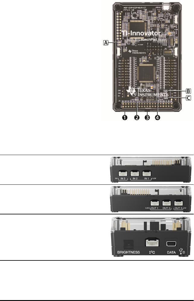
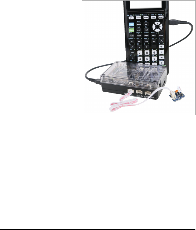
What's in the Box
TI-Innovator™Hub with On-Board
Components
ÀA Light Brightness Sensor at the bottom
of the Hub can be read as
"BRIGHTNESS" in Hub command strings.
ÁRed LED is addressable as "LIGHT" in
Hub command strings.
ÂSpeaker (at back of Hub, not shown) is
addressable as "SOUND" in Hub
command strings.
ÃRed-Green-Blue LED is addressable as
"COLOR" in Hub command strings.
Also visible on the face of the Hub are:
AGreen auxiliary power LED
BGreen power LED,
CRed error LED.
Built-in Ports
Left side-Three ports for collecting data or
status from input modules:
•IN1 and IN2 provide 3.3V power.
•IN3 provides 5V power.
Right side-Three ports for controlling output
modules:
•OUT1 and OUT2 provide 3.3V power.
•OUT3 provides 5V power.
Bottom-Light Brightness Sensor (described
earlier) and two ports:
•I2Cport connects to peripherals that use the
I2C communication protocol.
•DATAMini-B port, used with the appropriate
cable, connects to a compatible graphing
calculator or computer for data and power.
TI-Innovator™ Technology Getting Started Guide 3
4 TI-Innovator™ Technology Getting Started Guide
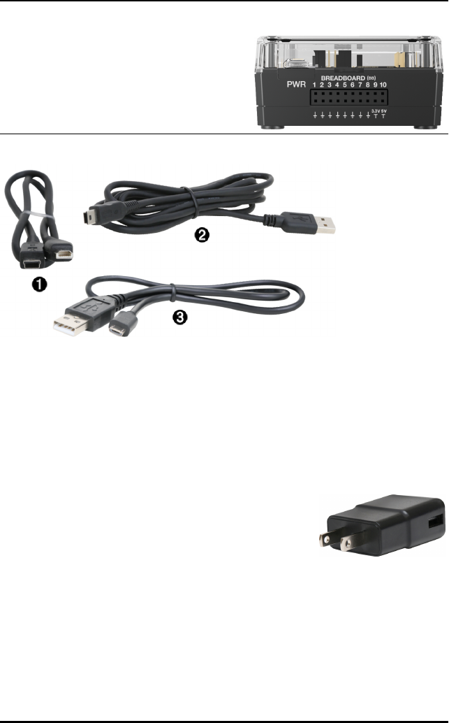
Top-Two connectors:
• USB-Micro connector (PWR) for auxiliary
power required by some components. Also
used for updating the Hub internal software.
• Breadboard Connector with 20 labeled pins
for communication with connected
components. A breadboard and jumper
cables are included with the TI-Innovator™
Breadboard Pack, sold separately.
USB Cables
ÀUSB Unit-to-Unit (Mini-A to Mini-B)-Connects the Hub to a TI CE Graphing
Calculator or a TI-Nspire™CX Handheld.
ÁUSB Standard A to Mini-B-Connects the Hub to a computer running
TI-Nspire™CXSoftware.
ÂUSB Standard A to Micro-Connects the PWR port of the Hub to a TI approved
power source required by some peripherals.
Auxiliary Power
TIWallCharger - Supplies power through the
TI-Innovator™Hub for components, such as motors, that
require additional power.
The optional External Battery Pack can also provide auxiliary
power.
Note: An auxiliary power LED on the Hub indicates when the
Hub is receiving auxiliary power.
Connecting TI-Innovator™Hub
The TI-Innovator™Hub connects by a USB cable to a graphing calculator or computer.
The connection lets the Hub receive power and exchange data with the host.
Note: Some peripherals, such as motors, may require auxiliary power. For more
information, see Using an Auxiliary Power Source (page 25).
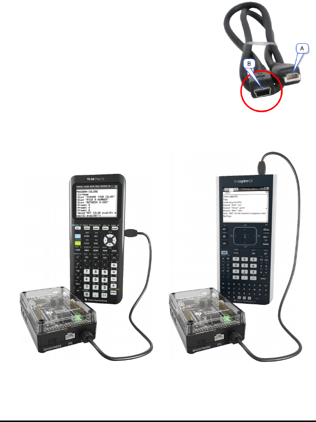
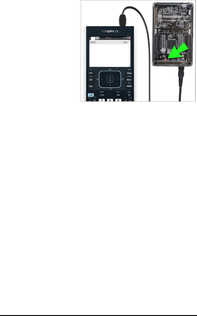
Connecting to a Graphing Calculator
1. Identify the "B" connector on the USB Unit-to-Unit
(Mini-A to Mini-B) cable. Each end of this cable is
embossed with a letter.
2. Insert the "B" connector into the DATA port at the
bottom of the TI-Innovator™Hub.
3. Insert the free end of the cable (the "A" connector) into the USB port on the
calculator.
Hub connected to
TI CE Graphing Calculator
Hub connected to
TI-Nspire™CX Handheld
TI-Innovator™ Technology Getting Started Guide 5
6 TI-Innovator™ Technology Getting Started Guide
4. Turn on the calculator if it is not already on.
The power LED on the Hub glows green to show that it is receiving power.
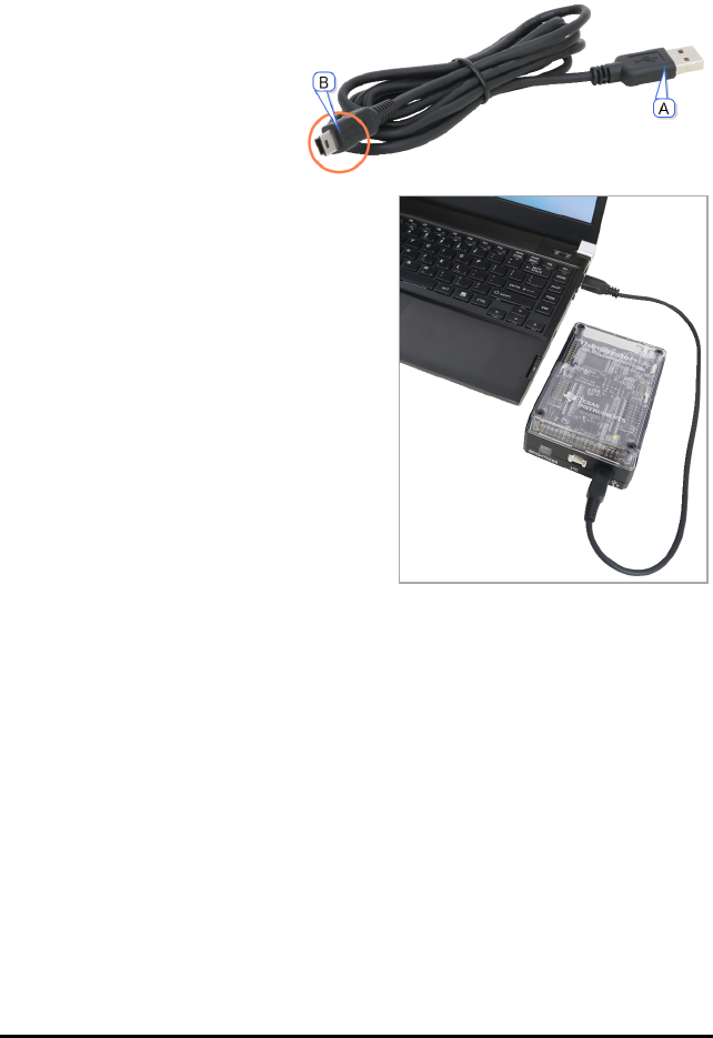
Connecting to a Computer Running TI-Nspire™CX Software
1. Identify the "B" connector on
the USB Standard A to Mini-B
cable for Windows®/Mac®.
Each end of this cable is
embossed with a letter.
2. Insert the "B" connector into
the DATA port at the bottom
of the TI-Innovator™Hub.
3. Insert the free end of the
cable (the "A" connector) into
a USB port on the computer.
The power LED on the Hub
glows green to show that it is
receiving power.

Updating the Hub Software
The TI-Innovator™Hub contains software, TI-Innovator™ Sketch, that interprets Hub
commands and communicates with on-board devices and connected modules. A Web-
based tool lets you update the Sketch. Updated versions contain bug fixes and ensure
that your TI-Innovator™Hub can communicate with the latest components.
To obtain the latest version of the TI-Innovator™ Sketch go to the following site:
https://education.ti.com/en/us/hubsw
TI-Innovator™ Technology Getting Started Guide 7
8 TI-Innovator™ Technology Getting Started Guide
Installing the Hub App on TICE Graphing Calculator
All TI CE Graphing Calculator running Operating System v5.2 can use TI-Innovator™Hub
commands. However, the Hub Menu for OS v5.2 resides in a separate Hub App.
To Download the App:
Note: This procedure applies only to TI CE Graphing Calculator Operating System v5.2
users who need to install or update the Hub App. To determine your calculator's OS
version, press y L and select About. To determine if the Hub App is already
installed, press y L, select Mem Management/Delete, select Apps, and look for
"Hub" in the list of installed Apps.
1. Make sure you have installed version 5.2 or later of the TI Connect™ CE Software on
your computer. You can download and install it free of charge.
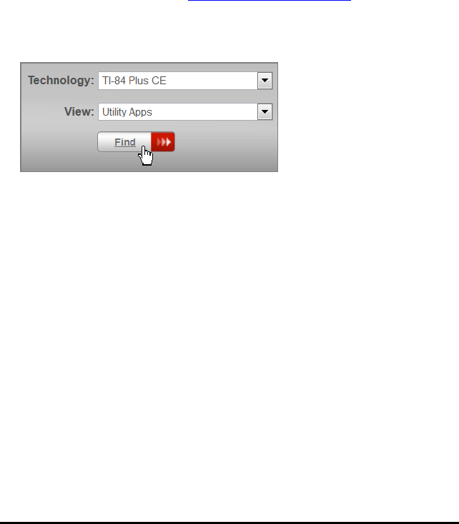
2. Use your Web browser to go to education.ti.com/go/download.
3. Select your preferred country and language.
4. On the download screen (for this example), select TI-84PlusCE, select Utility Apps,
and then click Find.
A list of Apps appears.
5. Click TI-Innovator™ Hub App to start the download process. Note the name of the
download file and the folder where you save it.
To Install or Update the App:
1. Connect the calculator to the computer, using the USB Standard A to Mini-B cable.
2. Open the TI Connect™CE software on the computer. It should recognize the
calculator.
3. On the Actions menu, select Add Files from Computer. You are prompted to choose
a file.
4. Navigate to the folder where you saved the App file, type *.8ek into the Filename
field, and press enter to show App files only.
5. Double-click the Hub App file that you downloaded.
6. On the Send to Calculator screen, Click Send.
Hub Programming on TI CE Graphing Calculator
Note: These instructions apply to TI CE graphing calculator. For similar instructions for
TI-Nspire™CX technology, refer to Hub Programming on TI-Nspire™ CX Technology
(page 14).
The TI-Innovator™Hub responds to TIBasic programming commands such as Send and
Get.
•Send - Sends command strings to the Hub to control devices or request
information.
•Get - Retrieves information requested from the Hub.
•eval - Supplies the result of an expression as a character string. Especially useful
within the Hub command string in Send commands.
•Wait - Pauses program execution for a specified number of seconds.
Code Examples: TI CE Graphing Calculator
Desired Action Program Code
Turn on the on-board Red LED ("LIGHT"). Send("SET LIGHT ON")
Play a 440Hz tone on the on-board
speaker ("SOUND") for 2 seconds.
Send("SET SOUND 440 TIME 2")
Turn on blue element of on-board RGB
LED ("COLOR") at 100% brightness.
Send("SET COLOR.BLUE 255")
Read and display the current value of the
on-board light sensor ("BRIGHTNESS").
Range is 0% to 100%.
Send("READ BRIGHTNESS")
Get(A):Disp A
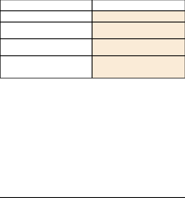
Sample Program to Blink an On-Board LED
The following TI CE graphing calculator program uses the Send and Wait commands to
blink the on-board red LED in the Hub. The commands are contained in a "For...End"
loop that repeats the ON/OFF blink cycle for 10 iterations.
TI-Innovator™ Technology Getting Started Guide 9
10 TI-Innovator™ Technology Getting Started Guide
PRGM: BLINK
For(N,1,10)
Send("SET LIGHT ON")
Wait 1
Send("SET LIGHT OFF")
Wait 1
End
How to Create and Execute a Program
Note: These are abbreviated instructions. For detailed instructions on creating and
executing programs, refer to TI-Basic Programming for the TI CE Graphing Calculator.
The guide is available through the TI-Innovator™ Technology eGuide (page ii).
Before You Begin
▶Refer to System Requirements (page 2), and update your calculator's OS
(Operating System) and Hub App, as needed. You can update from TIConnect™CE
software or from another updated calculator.
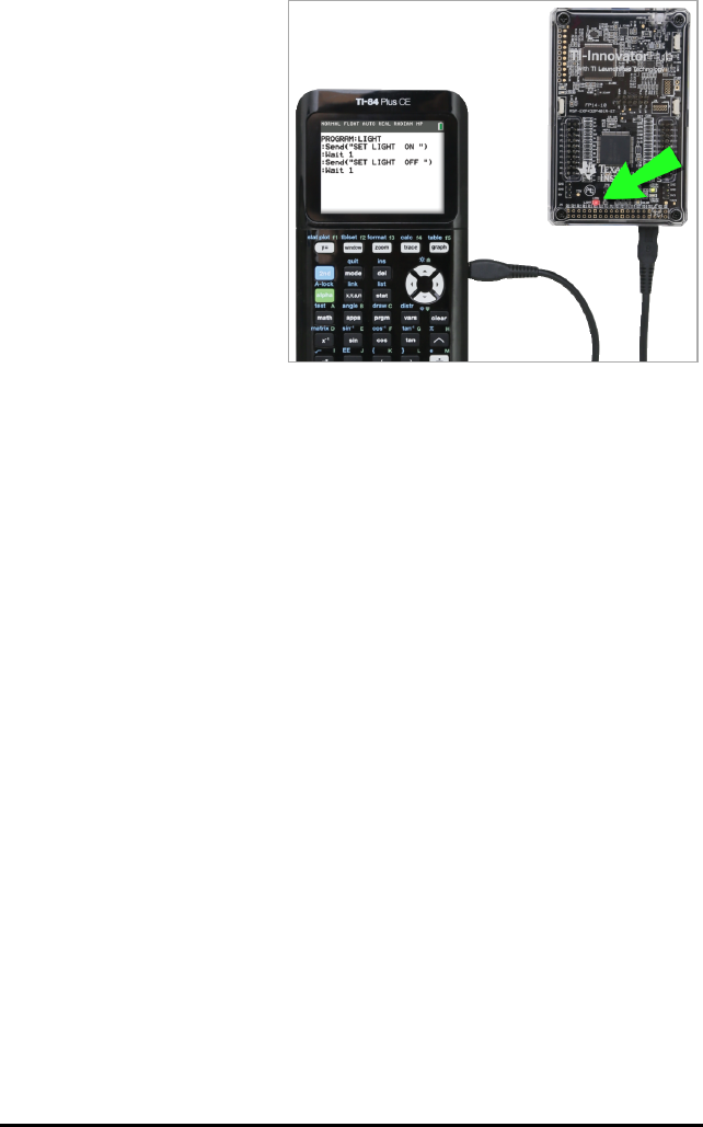
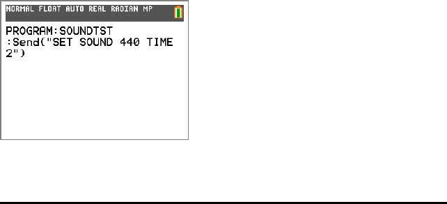
To Create a New Program on TI CE Graphing Calculator:
1. On the Home Screen, press ¼, select New, and press Í.
2. Type a name for your program, such as "SOUNDTST," and then press Í.
The Program Editor opens, displaying a template for your program code.
3. Enter the lines of code that make up your program.
- You must use the Hub Menu to enter TI-Basic commands, such as Send and
Get. (Press ¼and select Hub.)
- You can enter Hub command strinSetgs and parameters such as
"SETLIGHTON" by using the menu or by typing. If you type the strings,
make sure to use the correct case.
- At the end of each line, press Í. Each new line is automatically preceded by
a colon (:).
- Use the arrow keys to move through a program. Press {to delete, or press
y 6 to insert.
To Close the Program Editor
▶Press y 5 to return to the Home Screen.
The program remains available through the ¼key.
To Run the Program:
1. Ensure that the TI-Innovator™Hub is connected to your calculator.
2. Ensure that any needed I/O Modules or Breadboard components are connected to
the Hub.
3. From the Home Screen, press ¼, select your program name from the displayed
list, and press Í.
The program name is pasted to the Home Screen.
4. Press Íagain to run the program.
To Edit an Existing Program:
1. On the Home Screen, press ¼, select Edit.
2. Select the program name from the displayed list, and press Í.
The program opens in the Program Editor.
Using the Hub Menu to Build Commands
The Hub menu is available on the TI CE graphing calculator anytime you are creating or
editing a program. It can save you time building commands and help you with correct
command spelling and syntax.
Note: To build a command from the Hub menu, you need to know:
• The unique name of the component that you are addressing, such as "SOUND" for
the on-board speaker.
• The command parameters that apply to the component, such as sound frequency
and duration. Some parameters are optional, and you might need to know the
value range of a parameter.
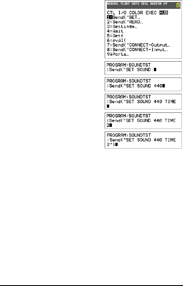
Example of Using the Hub Menu:
This TI CE graphing calculator example builds the command Send
("SETSOUND440TIME2") to sound a 440Hz tone for 2 seconds on the on-board
speaker.
1. Open (or create) the program that you will use to communicate with the Hub.
TI-Innovator™ Technology Getting Started Guide 11
12 TI-Innovator™ Technology Getting Started Guide
2. Position the cursor where you want to place the command.
3. Press ¼and select Hub.
The Hub menu appears.
4. Select Send "SET and press Í, and
then select SOUND and press Í.
5. Type 440 as the sound frequency.
6. On the Hub menu, select Settings >
TIME.
7. Type 2as the TIME value.
8. To complete the command, type closing
quotes (pressƒ Ã), and then
press¤.
9. To return to the Home Screen and test the command, press y 5 and then
follow the previous instructions for running a program.
Tips for Coding with TI CE Graphing Calculator
• Make sure your code is free of unnecessary spaces that can cause syntax errors.
This includes repeated spaces within the line and one or more spaces at the end of
a line.
• Code from an external source might show "curly" quotation marks (“...”) in places
that require straight quotes ("..."). To type straight quotes, press ƒand then Ã.
• To clear the current lineof code, press ‘.
• To type relational operators such as =,<, and ≤, press y :.
• To type a space, press ƒand thenÊ.
• If your program becomes unresponsive while running, press the Ékey.
•Note: If a command syntax does not include an opening left parenthesis, such as
"Wait ", using a pair of parentheses in an argument may be interpreted as the full
argument and give an unexpected syntax error. When entering long expressions
with parentheses, enclose the entire expression with paired parentheses to avoid
syntax errors of this nature.


14 TI-Innovator™ Technology Getting Started Guide
Hub Programming on TI-Nspire™CX Technology
Note: These instructions apply to TI-Nspire™CX technology. For similar instructions for
TI CE graphing calculator, refer to Hub Programming on TI CE Graphing Calculator
(page 9).
The TI-Innovator™Hub responds to TIBasic programming commands such as Send and
Get.
•Send - Sends command strings to the Hub to control devices or request
information.
•Get and GetStr - Retrieve information requested from the Hub.
•eval() - Supplies the result of an expression as a character string. Valid only within
Send,Get, and GetStr commands.
•Wait - Pauses program execution for a specified number of seconds.
Code Examples: TI-Nspire™CX Technology
Desired Action Program Code
Turn on the on-board Red LED ("LIGHT"). Send "SET LIGHT ON"
Play a 440Hz tone on the on-board
speaker ("SOUND") for 2 seconds.
Send "SET SOUND 440 TIME 2"
Turn on blue element of on-board RGB
LED ("COLOR") at 100% brightness.
Send "SET COLOR.BLUE 255"
Read and display the current value of the
on-board light sensor ("BRIGHTNESS").
Range is 0% to 100%.
Send "READ BRIGHTNESS"
Get a: Disp a
Sample Program to Blink an On-Board LED
The following TI-Nspire™ CX program uses the Send and Wait commands to blink the
on-board red LED in the Hub. The commands are contained in a "For...EndFor" loop that
repeats the ON/OFF blink cycle for 10 iterations.
Define blink()=
Prgm
For n,1,10
Send "SET LIGHT ON"
Wait 1
Send "SET LIGHT OFF"
Wait 1
EndFor
EndPrgm
How to Create and Execute a Program
Note: These are abbreviated instructions. For detailed instructions, refer to the
TI-Nspire™CX Program Editor, accessible through the TI-Innovator™ Technology eGuide
(page ii).
Before You Begin:
▶Refer to System Requirements (page 2), and update your software as needed.
- On TI-Nspire™ CX handhelds, use TI-Nspire™computer software to update the
Operating System.
- On computers running TI-Nspire™ CX software, use the Help menu to update
the software.
To Create a New Program in a TI-NspireCX Document:
1. On the handheld, press ~and select Insert > Program Editor > New.
From the computer software, click Insert > Program Editor > New.
2. Type a name for your program, such as "soundtst," select Program as the Type, and
then click OK.
The Program Editor opens, displaying a template for your program code.
3. Between the Prgm and EndPrgm lines, type the lines of code that make up your
program.
- You can either type command names or insert them from the Program Editor
menu.
- After typing each line, press Enter to type additional code.
- Use the arrow keys to scroll through the program.
To Store the Program:
You must store your program before you can run it.
TI-Innovator™ Technology Getting Started Guide 15

16 TI-Innovator™ Technology Getting Started Guide
▶On the handheld, press band select Check Syntax & Store > Check Syntax &
Store.
On the Program Editor menu, click Check Syntax & Store > Check Syntax & Store.
To Close the Program Editor
▶On the handheld, press band select Actions > Close.
On the Program Editor menu, click Actions > Close.
If you have made changes since storing the program, you are prompted to Check
Syntax & Store.
To Run the Program:
1. Ensure that the TI-Innovator™Hub is connected to your handheld or computer.
2. Ensure that any needed I/O Modules or Breadboard components are connected to
the Hub.
3. Open the document that contains the program.
4. On a Calculator page, type the program name and parentheses. If the program
requires arguments, enclose them in the parentheses, separated by commas.
The program runs.
To Edit an Existing Program:
1. If necessary, open the document that contains the program.
2. Go to a Calculator page.
3. On the handheld, press band select Functions & Programs > Program Editor >
Open.
On the Calculator menu, click Functions & Programs > Program Editor > Open.
4. Select the program name name from the displayed list.
The program appears in a Program Editor page.
Using the Hub Menu to Build Commands
The Hub menu is available on the TI-Nspire™CX technology anytime you are creating or
editing a program. It can save you time building commands and help you with correct
command spelling and syntax.
Note: To build a command from the Hub menu, you need to know:
• The unique name of the component that you are addressing, such as "SOUND" for
the on-board speaker.
• The command parameters that apply to the component, such as sound frequency
and duration. Some parameters are optional, and you might need to know the
value range of a parameter.
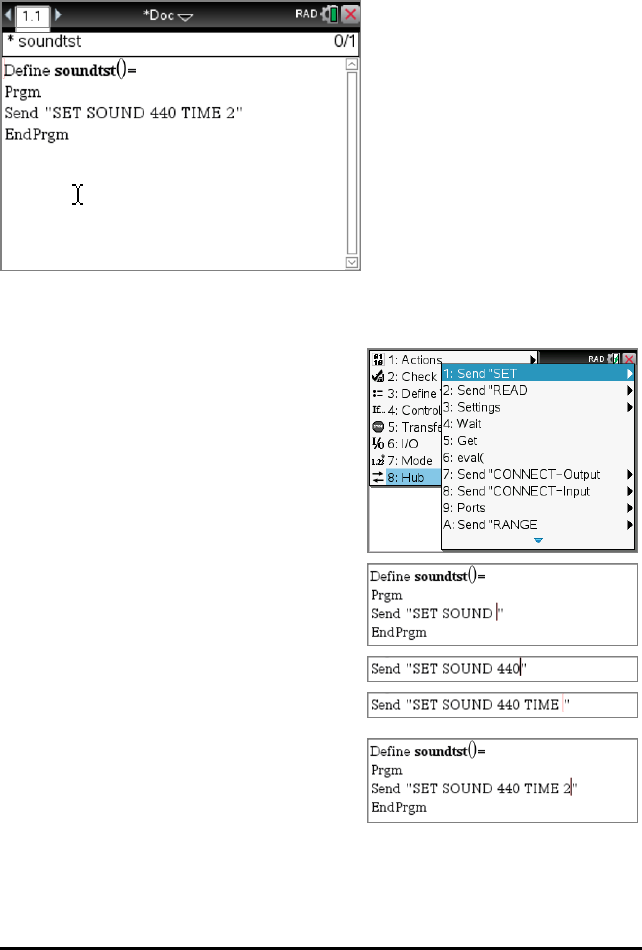
Example of Using the Hub Menu:
This TI-Nspire™CX example builds the command Send"SETSOUND440TIME2" to
sound a 440Hz tone for 2 seconds on the on-board speaker.
1. Open (or create) the program that you will use to communicate with the Hub.
2. Position the cursor where you want to place the command.
3. On the handheld, press band select
Hub.
In the Program Editor menu, select Hub.
The Hub menu appears.
4. Select Send "SET, and then select
SOUND to insert the first part of the
command.
5. Type 440 as the frequency value.
6. On the Hub menu, select Settings >
TIME.
7. To complete the command, Type 2as
the TIME value.
8. To test the command, follow the previous instructions for running a program.
TI-Innovator™ Technology Getting Started Guide 17

18 TI-Innovator™ Technology Getting Started Guide
Tips for Coding with TI-Nspire™CX Technology
• Code from an external source might contain "curly" quotation marks (“...”) in
places that require straight quotes ("..."). To type straight quotes, press/ r.
• To clear the current lineof code, press/ Ì.
• To type relational operators such as =,<, and ≤, press/ =.
• To type a space, press_.
• If your program becomes unresponsive while running:
TI-Nspire™CX Handheld: Hold down the ckey and press·repeatedly.
Windows®: Hold down the F12 key and pressEnter repeatedly.
Mac®: Hold down the F5 key and pressEnter repeatedly.
Learn More
To find sample programs and details about programming the TI-Innovator™Hub, see
the TI-Innovator™ Technology eGuide (page ii).
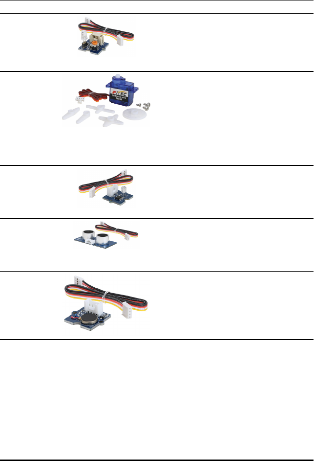
TI-Innovator™ I/O Modules
These Input/Output modules (purchased separately) include cables for connecting the
modules to the TI-Innovator™Hub.
Module Ports Image Sample code for TI CE Graphing Calculator
White
LED
*
OUT
1
OUT
2
OUT
3
Turn on the White LED module connected
to OUT1:
Send("CONNECT LED 1 TO OUT 1")
Send("SET LED 1 ON")
Servo
Motor
**
OUT
3
Rotate the shaft of the Servo Motor
connected to OUT3 counter clockwise by
90°:
Send("CONNECT SERVO 1 TO OUT 3")
Send("SET SERVO 1 TO -90")
Equivalent code using a variable with eval():
angdeg:=-90
Send("CONNECT SERVO 1 TO OUT 3")
Send("SET SERVO 1 TO eval(angdeg)")
Analog
Light
Sensor
IN1
IN2
IN3
Read and display ambient light level from
the sensor connected to IN2:
Send("CONNECT LIGHTLEVEL 1 TO IN2")
Send("READ LIGHTLEVEL 1")
Get(L):Disp(L)
Ultrasoni
c Ranger
IN1
IN2
Read and display measured distance from
the ranger connected to IN2:
Send("CONNECT RANGER 1 TO IN2")
Send("READ RANGER 1")
Get(R):Disp(R)
Vibration
Motor
OUT
1
OUT
2
OUT
3
Turn on the Vibration Motor connected to
OUT1:
Send("CONNECT VIB.MOTOR 1 TO OUT
1")
Send("SET VIB.MOTOR 1 TO ON")
*The White Led module requires some assembly.
**The Servo Motor requires auxiliary power and some assembly. For details, refer to
the TI-Innovator™ Technology eGuide (page ii).
Connecting an I/O Module
You use the I/O cable included with the module to connect it to a Hub Input or Output
port.
TI-Innovator™ Technology Getting Started Guide 19
20 TI-Innovator™ Technology Getting Started Guide
1. Check the above table to ensure that you know which I/O ports support the module
that you are connecting.
2. Connect either end of the I/O cable to the white connector on the module.
3. Connect the free end of the I/O cable to the Hub port you have decided to use.
4. If the module requires auxiliary power, connect the power source (page 25),
Sample Program to Blink an LED Module
The following TI CE graphing calculator program uses Send and Wait commands to
blink an LED module connected to an I/O port.
Note: This program operates correctly only if the calculator is connected to the Hub and
an LED module is physically connected to port OUT1.
PRGM: BLINKIO
Send("CONNECT LED 1 TO
OUT1")
For(N,1,10)
Send("SET LED 1 ON")
Wait 1
Send("SET LED 1 OFF")
Wait 1
End
Send("DISCONNECT LED 1")
Note: If you are using
TI-Nspire™CX technology, omit
the parentheses, and change End
to EndFor.
The Hub command string "CONNECT LED 1 TO OUT1" tells the Hub that an LED module
is connected to port OUT1 on the Hub. After sending this command, the code can
address the LED as "LED 1." The CONNECT command is required only for I/O Modules
and Breadboard components. It is not necessary with the on-board components such as
the built-in speaker.
Learn More
For a list of precautions to take while using the I/O Modules, refer to General
Precautions (page 29).
To find sample programs, a list of additional I/O Modules, and details about
programming I/O Modules, see the TI-Innovator™ Technology eGuide (page ii).
TI-Innovator™ Breadboard Pack
The breadboard and its components (purchased separately) let you build breadboard
projects and connect them to the TI-Innovator™Hub through its Breadboard Connector
pins.
The breadboard components include:
• A breadboard and jumper cables for creating electrical connections.
• Addressable components, such as LEDs and sensors, that respond to Hub
commands. These are listed in the table below.
• Passive components, such as resistors, capacitors, and manual switches that are
not directly addressable by the Hub but are required in many breadboard projects.
• A Battery Holder that holds four AA batteries. Batteries are not included.
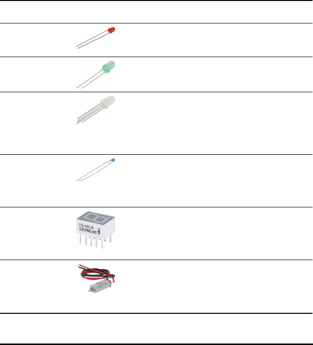
Addressable Components
Component Image Used with
pins
Description
Red LEDs BB 1-10 Light-emitting diode that
emits light when current
passes through it.
Green LEDs BB 1-10 Light-emitting diode that
emits light when current
passes through it.
RGB (Red-
Green-Blue)
LEDs
BB 8-10 Light-emitting diode
with independently
adjustable red, green
and blue elements. Can
produce a wide variety
of colors.
Thermistor BB 5,6,7
(analog
input
required)
Resistor whose
resistance changes based
on temperature. Used
for measurement and
control.
7-segment
Display
BB 1-10 Array of LEDs arranged to
display numbers and
some alphabetic
characters. Also has an
LED for a decimal point.
Small DC
Motor
BB 1-10
(uses digital
to generate
software
PWM)
Motor that converts
direct current electrical
power into mechanical
power.
TI-Innovator™ Technology Getting Started Guide 21
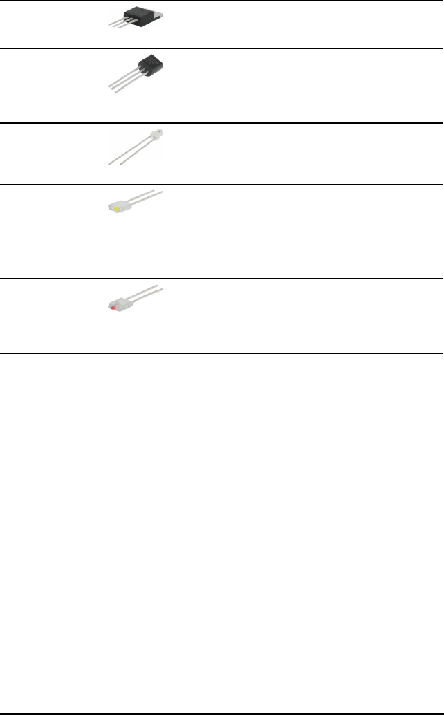
22 TI-Innovator™ Technology Getting Started Guide
TTL Power
MOSFET
BB 1-10 Transistorused for
amplifying or switching
electronicsignals.
TI Analog
Temperature
Sensor
BB 5,6,7
(analog
input
required)
Sensor that reports a
voltage proportional to
the ambient
temperature within a
range of −55°C to 130°C.
Visible Light
Sensor
BB 5,6,7
(analog
input
required)
Sensor that reports the
level of ambient light.
Infrared
Transmitter
LTE-302,
yellow dot
BB 1-10
(digital
output)
Side emitting Infrared
LED, designed to be
paired with the LTR-301
Photo-Transistor.
Infrared
Receiver
LTR-301,
red dot
BB 1-10
(digital
input)
Side sensing Infrared
photo transistor,
designed to be paired
with the LTE-302
Infrared Emitter.
Sample Code to Blink a Breadboard LED
The following TI CE graphing calculator(s) program uses Send and Wait commands to
blink a specific LED on the breadboard.
Note: This program operates correctly only if the calculator is connected to the Hub and
the LED is physically connected to BB1 (breadboard pin 1) on the Hub.
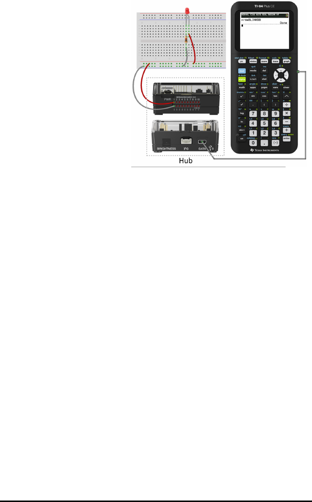
PRGM: BLINKBB
Send("CONNECT LED 1 TO BB1")
For(N,1,10)
Send("SET LED 1 ON")
Wait 1
Send("SET LED 1 OFF")
Wait 1
End
Send("DISCONNECT LED 1")
Note: If you are using
TI-Nspire™CX technology, omit
the parentheses, and change End
to EndFor.
The Hub command string "CONNECT LED 1 TO BB1" tells the Hub that an LED on the
breadboard is connected to pin 1on the Hub. After sending this command, your code
can address the LED as "LED 1." The CONNECT command is required only for I/O
Modules and breadboard components. It does not apply to on-board components such
as the built-in speaker.
Breadboard Basics
The breadboard makes it easy to connect the electronic components of a project by
inserting component leads and jumper cables into pins on the breadboard.
The pins are arranged in groups of 5. The 5 pins in each group are electrically
connected to each other at the back of the board. You connect leads and cables
together by inserting them into pins within the same group.
• Power rails at the top and bottom are marked with red (+) and blue (–) stripes. The
groups in each rail are electrically connected along the entire length of the stripe.
• The remaining 5-pin groups on the board are labeled with numbers and letters.
Each group is electrically isolated from the others.
TI-Innovator™ Technology Getting Started Guide 23

24 TI-Innovator™ Technology Getting Started Guide
Front of board showing power rails and connection
pins
Interconnections at back of board (normally
hidden). The 5-pin groups in each power rail are
interconnected. All other 5-pin groups are
isolated.
The gap at the center of the breadboard allows easy connection of electronic
components provided as dual-inline packages.
You use jumper cables between the Hub and the breadboard to power breadboard
components and to control or monitor them through program code. The Hub has 20
labeled pins, including 10 signal pins, 8 ground pins, one 3.3V power pin, and one 5.0V
power pin.
Learn More
For a list of precautions to take while using the breadboard and its components, refer
to General Precautions (page 29).
To find sample programs and details about programming breadboard components on
the TI-Innovator™Hub, see the TI-Innovator™ Technology eGuide (page ii).

Using an Auxiliary Power Source
Normally, the TI-Innovator™Hub and its connected components draw power from the
host calculator or computer, through the DATA connector. Certain components, such as
the optional Servo Motor, require more power than a calculator can provide reliably.
The PWR connector on the Hub lets you connect an auxiliary power source. You can use
the TIWallCharger or the External Battery Pack.
TIWallCharger (included with the Hub)
• Plugs into a wall outlet.
• Does not use batteries.
External Battery Pack(sold separately)
• Rechargeable.
• Has On/Off button with a row of LEDs that
momentarily indicate the battery charge
when you turn the battery on.
• Turns itself off after being disconnected
from the Hub for about 3 minutes.
Note:To recharge the External Battery Pack,
disconnect it from the Hub and then connect
it to the TIWallCharger using the USB
Standard A to Micro cable. Do not use the
External Battery Pack as an auxiliary power
source while it is being charged.
Connecting the Power Source
1. Identify the Micro connector on the
USB Standard A to Micro auxiliary
power cable.
2. Insert the Micro connector into the
PWR connector at the top of the Hub.
TI-Innovator™ Technology Getting Started Guide 25

26 TI-Innovator™ Technology Getting Started Guide
3. Insert the free end of the cable (the "A" connector) into the USB port on the power
source.
4. Turn on the power source:
- If using the TIWallCharger, plug it into a wall socket.
- If using the External Battery Pack, press the power button.
An auxiliary power LED on the Hub glows to show that the Hub is receiving auxiliary
power.
5. Connect the TI-Innovator™Hub to the host calculator, using the USB Standard A to
Mini-B cable.
6. Connect the I/O Module or breadboard component to the Hub.

Troubleshooting
Idon't see the green LED when Iconnect TI-Innovator™Hub.
• Make sure that the calculator is turned on.
• If you are using a USB Unit-to-Unit (Mini-A to Mini-B) cable to connect to a
calculator, make sure to connect the "B" end of the cable to the DATA connector at
the bottom of the Hub. Reversing this cable prevents the Hub from receiving
power.
• Make sure your calculator or computer meets the System Requirements (page 2).
• Make sure the end of the USB cable connected to the calculator is inserted
completely.
How do I turn the Hub off?
1. Turn off the host calculator or computer.
– OR –
Disconnect the USB cable.
2. Disconnect any auxiliary power source connected to the PWR port on the Hub.
Why does my program give me a syntax error?
• If you have pasted code from an external source or text editor, it might contain
"curly" quotation marks (“...”) in places that require straight quotes ("..."). You
may need to replace some or all of the curly quotes.
• The syntax rules are slightly different between the TI CE graphing calculator and
TI-Nspire™CX technology. Code originally created for one platform may need to be
modified to work on the other.
• On the TI CE graphing calculator, make sure you don't have a space character at the
end of a line of code. To find these trailing spaces in a line, move the cursor to the
line and press y ~. Adjacent spaces in code can also cause a syntax error.
How do Istop a program that becomes unresponsive?
• TI CE graphing calculator: Press the Ékey.
• TI-Nspire™CX Handheld: Hold down the ckey and press ·repeatedly.
• Windows®: Hold down the F12 key and press Enter repeatedly.
• Mac®: Hold down the F5 key and press Enter repeatedly.
Why do I get an error when Itry to update the TI-Innovator™ Sketch?
• For sketch updating, make sure you are using the USB Standard A to Micro cable,
not the USB Standard A to Mini-B cable. Connect the micro end of the cable to the
PWR connector at the top of the Hub.
• Make sure you are using one of the Web browsers required for updating. See
Updating the Hub Software (page 7).
TI-Innovator™ Technology Getting Started Guide 27


General Precautions
TI-Innovator™Hub
• Do not expose the Hub to temperatures above 140˚F (60˚C).
• Do not disassemble or mistreat the Hub.
• Do not chain together multiple Hubs through the I/O ports or the Breadboard
Connector.
• Use only the USB cables provided with the Hub.
• Use only the TI provided power supplies:
- TIWallCharger included with the TI-Innovator™Hub
- Optional External Battery Pack
- 4AA battery holder included in the TI-Innovator™ Breadboard Pack
• Ensure that the components receiving power from the Hub do not exceed the Hub's
1-amp power limit.
• Avoid using the Hub to control AC electricity.
Breadboard Connector on the Hub
• Do not insert the leads of LEDs and other components directly into the Hub’s
Breadboard Connector. Assemble the components on the breadboard and use the
provided jumper cables to connect the breadboard to the Hub.
• Do not connect the 5V receptacle pin on the Hub's Breadboard Connector to any of
the other pins, especially the ground pins. Doing so could damage the Hub.
• Connecting the top row of receptacle pins (BB1-10) to the bottom row (grounding
and power pins) is not recommended.
• No pin on the Hub's Breadboard Connector can sink or source greater than 4 mA.
Breadboard
• Do not connect the positive and negative leads of a power source to the same
group of 5 pins on the breadboard. Doing so could damage the breadboard and the
power source.
• Observe the correct polarity:
- When connecting the breadboard to the Hub.
- When connecting components that are sensitive to polarity, such as LEDS and
the TTL Power MOSFET.
I/O Modules
• Use the correct Input or Output port as required for each module.
- Vibration Motor – supported on OUT1,OUT2, and OUT3.
- Servo Motor – use OUT3 only.
- White LED – supported on OUT1,OUT2, and OUT3.
- Analog Light Sensor – supported on IN1,In2, and IN3.
- Ultrasonic Ranger – supported on IN1,IN2.
TI-Innovator™ Technology Getting Started Guide 29

30 TI-Innovator™ Technology Getting Started Guide
• Use an Auxiliary Power Source for modules that require more than 50 mA,
including:
- Vibration Motor
- Servo Motor
• Do not hold the Servo Motor’s shaft while it is rotating. Also, do not rotate the
Servo Motor by hand.
• White LED:
- Do not bend the leads repeatedly; this will weaken the wires and may cause
them to break.
- The LED requires the correct polarity when inserted into its socket. For details,
refer to the instructions for assembling the LED in the TI-Innovator™
Technology eGuide (page ii).
- The LED requires the correct polarity when inserted into its socket. For details,
refer to the instructions for assembling the LED (page 63).
• No I/O module can sink or source greater than 4 mA.
TI-Innovator™Rover
• Do not expose the Rover to temperatures above 140˚F (60˚C).
• Do not disassemble or mistreat the Rover.
• Do not put anything heavier than 1 Kg or 2.2 lbs on the Rover platform.
• Use only the USB cables provided with the TI-Innovator™ Hub.
• Use only the Ribbon cables provided with the Rover.
• Use only the TI provided wall charger included with the Hub.
• The front-mounted Ultrasonic Ranger will detect objects within 4 meters of the
Rover. For best results make sure the object's surface is bigger than a folder. If
used to detect small objects, such as a cup, place the Rover within 1 meter of the
object.
• For best results, leave the Slide Case off of your graphing calculator.
• For best performance, use Rover on the floor, not on tables. Damage may occur
from Rover falling off a table.
• For best performance, use Rover on a hard surface. Carpet may cause the Rover
wheels to catch or drag.
• Do not turn the Holder pegs on the Calculator Platform without lifting them first.
They could break.
• When securing a marker in the Marker Holder avoid over-tightening the screw.
• Do not use the marker as a lever to pull or push the Rover.
• Do not unscrew the case enclosure on the bottom of the Rover. Encoders have
sharp edges that should not be exposed.
• Do not move Rover after executing a program. The internal gyroscope may
unintentionally try to get the Rover back on track using the initial location.

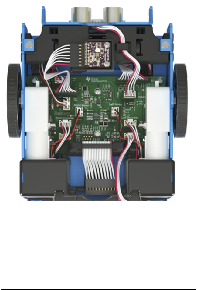
• When inserting the Breadboard Ribbon Cable into the Hub Breadboard Connector, it
is critical that you insert the cable correctly. Make sure the red (dark) wire pin is
inserted into the 5v hole on the Hub's Breadboard Connector.
TI-Innovator™ Technology Getting Started Guide 31
32 TI-Innovator™ Technology Getting Started Guide
Caution: If you dislodge or disconnect any of the cables, use this image as a reference
for correct hookups.
Reference to Bottom View
TI-Innovator™ Hub Commands version 1.2
Use the Hub menus to create or edit a program. They can save you time building
commands and help you with correct command spelling and syntax.
When you see "Code Sample" in a command table, this "Code Sample" may be copied
and pasted as is to send to your graphing calculator to use in your calculations.
Example:
Code
Sample:
Send("RV FORWARD")
Send("RV FORWARD SPEED 0.2 M/S TIME 10")
Note: To build a command from the Hub menu, you need to know:
• The unique name of the component that you are addressing, such as "SOUND" for
the on-board speaker.
• The command parameters that apply to the component, such as sound frequency
and duration. Some parameters are optional, and you might need to know the
value range of a parameter.
Understanding Syntax
• Capitalized words are keywords
• Lower case words are placeholders for numbers
• Commands within brackets are optional parameters
For example in: SET LIGHT ON [[BLINK|TOGGLE] frequency] [[TIME] seconds],
"frequency" is entered as "1" and "seconds" is entered as "10".
Send("SET LIGHT 1 BLINK 2 TIME 10")
NOTE: The commands listed below are for the TI-84 Plus CE Hub Menu. If you are using
TI-Nspire™ CX technology the parentheses are omitted. In addition, you will notice
some other minor differences in the commands such as "Endfor" instead of "End" with
the TI-Nspire™ CX technology. Screenshots are provided for reference.
HUB Menus
–Send("SET...
–Send("READ...
–Settings
–Wait
–Get(
–eval(
–Rover (RV) ...
TI-84 Plus CE TI-Nspire™ CX
TI-Innovator™ Hub Commands version 1.2 33
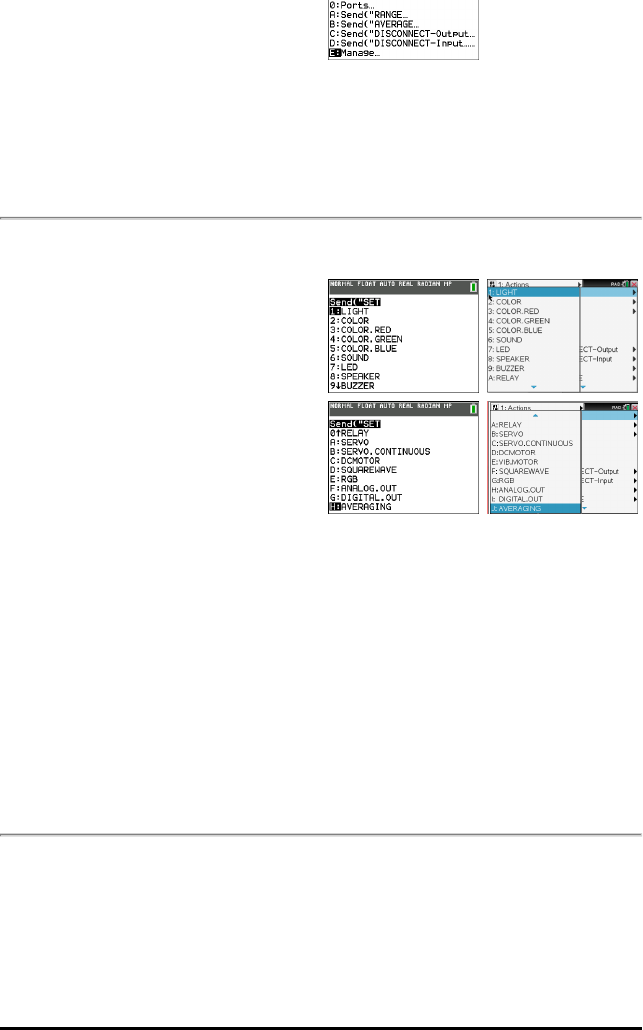
34 TI-Innovator™ Hub Commands version 1.2
–Send("CONNECT-Output...
–Send("CONNECT-Input...
–Ports...
–Send("RANGE...
–Send("AVERAGE...
–Send("DISCONNECT-Output...
–Send("DISCONNECT-Input...
–Manage...
Send("SET...
•SET
–LIGHT
–COLOR
–COLOR.RED
–COLOR.GREEN
–COLOR.BLUE
–SOUND
–LED
–SPEAKER
–BUZZER
–RELAY
–SERVO
– SERVO.CONTINOUS
–DCMOTOR
–VIB.MOTOR
–SQUAREWARE
–RGB
–ANALOG.OUT
–DIGITAL.OUT
–AVERAGING
TI-84 Plus CE TI-Nspire™ CX
Additional Set Commands
Send("READ...
•READ
–BRIGHTNESS
–DHT
–RANGER
TI-84 Plus CE TI-Nspire™ CX
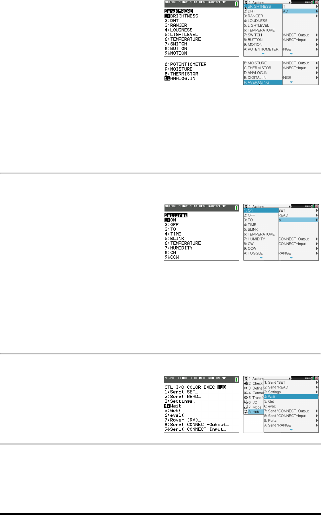
–LOUDNESS
–LIGHTLEVEL
–TEMPERATURE
–SWITCH
–BUTTON
–MOTION
–POTENTIOMETER
–MOISTURE
–THERMISTOR
–ANALOG.IN
–DIGITAL.IN
–AVERAGING
Additional READ Commands
Settings...
• Settings
– ON
– OFF
– TO
– TIME
– BLINK
– TEMPERATURE
– HUMIDITY
– CW
– CCW
– TOGGLE
TI-84 Plus CE TI-Nspire™ CX
Wait
•Wait
TI-84 Plus CE TI-Nspire™ CX
Get(
•Get(
TI-84 Plus CE TI-Nspire™ CX
TI-Innovator™ Hub Commands version 1.2 35
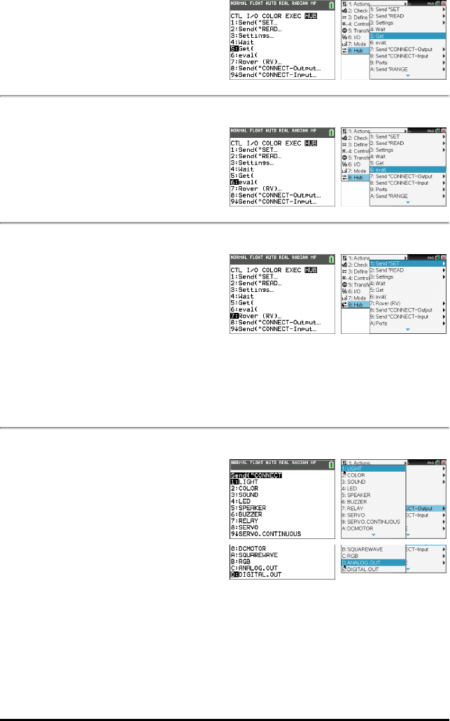
36 TI-Innovator™ Hub Commands version 1.2
eval(
•eval(
TI-84 Plus CE TI-Nspire™ CX
Rover (RV)...
–Drive RV…
–Read RV Sensors…
–RV Settings…
–Read RV Path…
–RV Color…
–RV Setup…
–RV Control…
–Send "CONNECT RV"
–Send "DISCONNECT RV"
TI-84 Plus CE TI-Nspire™ CX
Send("CONNECT-Output...
•CONNECT-Output
–LIGHT
–COLOR
–SOUND
–LED
–SPEAKER
–BUZZER
–RELAY
–SERVO
–SERVO.CONTINUOUS
–DCMOTOR
–SQUAREWAVE
–RGB
TI-84 Plus CE TI-Nspire™ CX
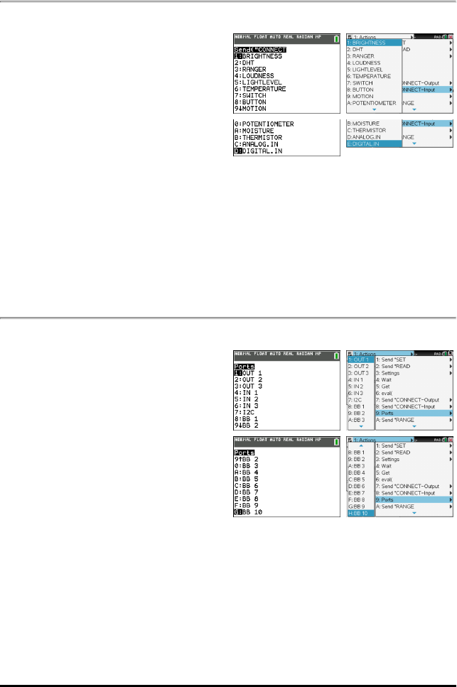
–ANALOG.OUT
–DIGITAL.OUT
Send("CONNECT-Input...
•CONNECT-Input
–BRIGHTNESS
–DHT
–RANGER
–LOUDNESS
–LIGHTLEVEL
–TEMPERATURE
–SWITCH
–BUTTON
–MOTION
–POTENTIOMETER
–MOISTURE
–THERMISTOR
–ANALOG.IN
–DIGITAL.IN
TI-84 Plus CE TI-Nspire™ CX
Ports...
• Ports
– OUT 1
– OUT 2
– OUT 3
– IN 1
– IN 2
– IN: 3
– I2C
– BB 1
– BB 2
– BB 3
– BB 4
– BB 5
– BB 6
– BB 7
– BB 8
– BB 9
TI-84 Plus CE TI-Nspire™ CX
TI-Innovator™ Hub Commands version 1.2 37
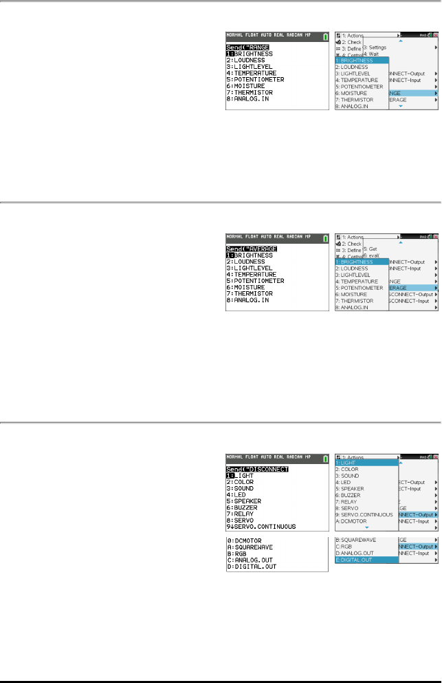
38 TI-Innovator™ Hub Commands version 1.2
– BB 10
Send("RANGE...
•RANGE
–BRIGHTNESS
–LOUDNESS
–LIGHTLEVEL
–TEMPERATURE
–POTENTIOMETER
–MOISTURE
–THERMISTOR
–ANALOG.IN
TI-84 Plus CE TI-Nspire™ CX
Send("AVERAGE...
•AVERAGE
–BRIGHTNESS
–LOUDNESS
–LIGHTLEVEL
–TEMPERATURE
–POTENTIOMETER
–MOISTURE
–THERMISTOR
–ANALOG.IN
TI-84 Plus CE TI-Nspire™ CX
Additional AVERAGE Commands
Send("DISCONNECT-Output...
•DISCONNECT-Output...
–LIGHT
–COLOR
–SOUND
–LED
–SPEAKER
–BUZZER
–RELAY
–SERVO
–SERVO.CONTINUOUS
–DCMOTOR
TI-84 Plus CE TI-Nspire™ CX
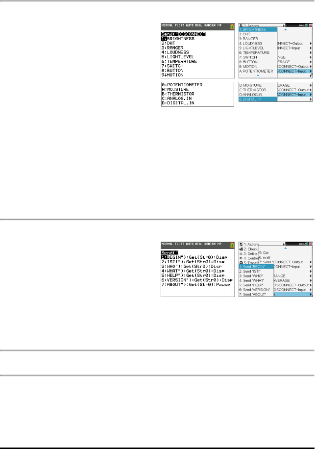
–SQUAREWAVE
–RGB
–ANALOG.OUT
–DIGITAL.OUT
Send("DISCONNECT-INPUT...
•DISCONNECT-Input...
–BRIGHTNESS
–DHT
–RANGER
–LOUDNESS
–LIGHTLEVEL
–TEMPERATURE
–SWITCH
–BUTTON
–MOTION
–POTENTIOMETER
–MOISTURE
–THERMISTOR
–ANALOG.IN
–DIGITAL.IN
TI-84 Plus CE TI-Nspire™ CX
MANAGE
•MANAGE
–BEGIN
–ISTI
–WHO
–WHAT
–HELP
–VERSION
–ABOUT
TI-84 Plus CE TI-Nspire™ CX
Additional Supported Commands Not Found in the Hub Menu
•Additional SET Commands
–FORMAT ERROR STRING/NUMBER
–FORMAT ERROR NOTE/QUIET
–FLOW [TO] ON/OFF
TI-Innovator™ Hub Commands version 1.2 39

40 TI-Innovator™ Hub Commands version 1.2
–OUT1/2/3 [TO]
•Additional READ Commands
–ANALOG.OUT
–BUZZER
–COLOR
–RED
–GREEN
–BLUE
–DCMOTOR i
–DIGITAL.OUT i
–FORMAT
–FLOW
–IN1/IN2/IN3
–LAST ERROR
–LED i
–LIGHT
–OUT1/2/3
–PWR
–RELAY i
–RESOLUTION
–RGB i
–RED i
–GREEN i
–BLUE i
–SERVO i
–SERVO i CALIBRATION
–SOUND
–SPEAKER i
–SQUAREWAVE i
•Additional AVERAGE Commands
–PERIOD
•Additional CALIBRATE Commands
–CALIBRATE
–SERVO i minimum maximum
–TEMPERATURE i c1 c2 c3 r
–THERMISTOR i c1 c2 c3 r

TI-Innovator™ Hub Commands version 1.2 41
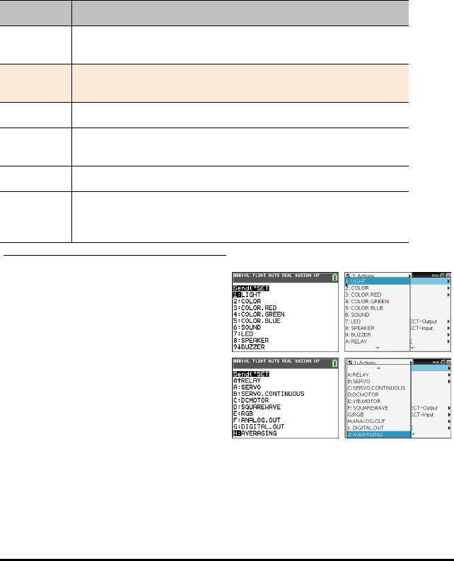
42 TI-Innovator™ Hub Commands version 1.2
SET
The SET command is used to generate outputs on pins or ports, or control output
devices such as LEDs, Servo motors, speaker tones, or other output operations. It is
also used to control a variety of system settings. These include formatting of error
information, and communications flow control. SET does NOT generate any response
that requires reading. The success or failure of a SET command may be determined by
sending a READ LAST ERROR command and obtaining the response to that command.
The sensors, controls, and settings that SET can operate against are in the following
table.
SET something'
Command: SET
Command
Syntax:
SET
Code
Sample:
Range:
Describe: Used to set options, or output states, or provide information used to
control an external actuator or output device, such as turning on a RELAY.
Result:
Type or
Addressable
Component:
TI-84 Plus CE TI-Nspire™ CX

LIGHT [TO] ON/OFF
Command: LIGHT [TO] ON/OFF
Command
Syntax:
SET LIGHT ON [[BLINK|TOGGLE] frequency] [[TIME] seconds]
SET LIGHT OFF
- same as LED, but for on-board red LED.
Range:
Describe: Provides control over the on-board digital RED LED. Set optional blink
frequency and duration.
SET LIGHT ON [[BLINK|TOGGLE] frequency] [[TIME] seconds]
SET LIGHT OFF
Result: Turns on LIGHT.
Turns off LIGHT
Type or
Addressable
Component:
Control
COLOR [TO] r g b [[BLINK|TOGGLE] frequency] [[TIME] seconds]
Command: COLOR [TO] r g b [[BLINK|TOGGLE] frequency] [[TIME] seconds]
Command
Syntax:
SET COLOR r g b [[BLINK|TOGGLE] frequency] [[TIME]seconds]
SET COLOR.component x [[BLINK|TOGGLE] frequency] [[TIME]seconds]
Range:
Describe: On-board COLOR RGB LED with sub-components .RED,.GREEN,.BLUE.
Can have a blink frequency, and blink time for entire item, or for each
component individually, as well as PWM levels given individually, or at one
time.
Result: Where r g b is r-value g-value b-value respectively, or operators from
ON/OFF/UP/DOWN/STOP.
Type or
Addressable
Component:
Control
See Also:
TI-Innovator™ Hub Commands version 1.2 43

44 TI-Innovator™ Hub Commands version 1.2
COLOR.RED [TO] r [[BLINK|TOGGLE] frequency] [[TIME] seconds]
Command: COLOR.RED [TO] r [[BLINK|TOGGLE] frequency] [[TIME] seconds]
Command
Syntax:
Send("SET COLOR.RED...")
ON/OFF/UP/DOWN/STOP/0-255 (red element)
[BLINK frequency] (in Hz)
[TIME duration] (in secs)
Range:
Describe: RED component of On-board COLOR RGB LED. Can have a blink
frequency, and blink time for entire item, or for each component
individually, as well as PWM levels given individually, or at one time.
Result: Where r is red level, or operators from ON/OFF/UP/DOWN/STOP.
Type or
Addressable
Component:
Control
COLOR.GREEN [TO] g [[BLINK|TOGGLE] frequency] [[TIME] seconds]
Command: COLOR.GREEN [TO] g [[BLINK|TOGGLE] frequency] [[TIME]
seconds]
Command
Syntax:
SET COLOR.GREEN [TO] g [[BLINK|TOGGLE] frequency] [[TIME] seconds]
Range:
Describe: GREEN component of On-board COLOR RGB LED. Can have a blink
frequency, and blink time for entire item, or for each component
individually, as well as PWM levels given individually, or at one time.
Result: Where g is green level, or operators from ON/OFF/UP/DOWN/STOP.
Type or
Addressable
Component:
Control

COLOR.BLUE [TO] b [[BLINK|TOGGLE] frequency] [[TIME] seconds]
Command: COLOR.BLUE [TO] b [[BLINK|TOGGLE] frequency] [[TIME]
seconds]
Command
Syntax:
SET COLOR.BLUE [TO] b [[BLINK|TOGGLE] frequency] [[TIME] seconds]
Range:
Describe: BLUE component of On-board COLOR RGB LED.Can have a blink
frequency, and blink time for entire item, or for each component
individually, as well as PWM levels given individually, or at one time.
Result: Where b is blue level, or operators from ON/OFF/UP/DOWN/STOP.
Type or
Addressable
Component:
Control
SOUND [TO] frequency [[TIME] seconds]
Command: SOUND [TO] frequency [[TIME] seconds]
Command
Syntax:
SET SOUND frequency [[TIME] seconds]
Range:
Describe: SOUND is the on-board speaker and can generate a sound with a specified
frequency. If not specified, sound will play for 1 second default.
SET SOUND frequency [[TIME] seconds]
Result: Play tone through on-board speaker.
Type or
Addressable
Component:
Control
SOUND OFF/0
Command: SOUND OFF/0
Command
Syntax:
SET SOUND 0
TI-Innovator™ Hub Commands version 1.2 45

46 TI-Innovator™ Hub Commands version 1.2
Command: SOUND OFF/0
Range:
Describe: SOUND is the on-board speaker and can generate a sound with a specified
frequency. If not specified, sound will play for 1 second default.
SET SOUND 0 – turns off sound on internal speaker immediately.
Result: Stop playing sound.
Type or
Addressable
Component:
Control
LED i [TO] ON/OFF
Command: LED i [TO] ON/OFF
Command
Syntax:
SET LED i ON/ OFF [[BLINK|TOGGLE] frequency] [[TIME] seconds]
– digital LED (on or off only)
Range:
Describe: Provides control over an external LED to set optional blink frequency and
duration, as well as PWM capability if the associated pin connected to the
LED supports it.
SET LED i ON [[BLINK|TOGGLE] frequency] [[TIME] seconds] – digital LED
(on or off only)
SET LED i OFF – turns off LED (same as SET LED i 0).
Result: Turns on LED.
Turns off LED
When connected to an Analog-PWM pin.
Type or
Addressable
Component:
Control

LED i [TO] 0-255
Command: LED i [TO] 0-255
Command
Syntax:
SET LED i 0-255 [[BLINK|TOGGLE] frequency] [[TIME] seconds]
– analog LED (pwm duty cycyle)
Range:
Describe: Provides control over an external LED to set optional blink frequency and
duration, as well as PWM capability if the associated pin connected to the
LED supports it.
SET LED i 0-255 [[BLINK|TOGGLE] frequency] [[TIME] seconds] – analog
LED (pwm duty cycyle)
Result: When connected to an Analog-PWM pin.
Type or
Addressable
Component:
Control
SPEAKER i [TO] frequency [[TIME] seconds]
Command: SPEAKER i [TO] frequency [[TIME] seconds]
Command
Syntax:
SET SPEAKER i [TO] frequency [[TIME] seconds]
Range:
Describe: Same as SOUND above, except sound is played on an external speaker
attached to a digital output pin, available on any IN/OUT port, or the
breadboard connector port.
Note: On-board SOUND and external SPEAKER cannot be used
concurrently.
Result: Play tone with frequency given, optional duration in milliseconds, default =
1 second.
Type or
Addressable
Component:
Control
TI-Innovator™ Hub Commands version 1.2 47

48 TI-Innovator™ Hub Commands version 1.2
BUZZER i [TO] ON [TIME seconds]
Command: BUZZER i [TO] ON [TIME seconds]
Command
Syntax:
SET BUZZER i ON [[TIME] seconds]
Range:
Describe: Used to turn ON or OFF a tone on an active BUZZER for either 1 second
default, or given length of time.
SET BUZZER i ON [[TIME] seconds]
Result: Sound tone on ACTIVE buzzer for 1 second, or specified duration in
seconds.
Type or
Addressable
Component:
Control
BUZZER i [TO] OFF
Command: BUZZER i [TO] OFF
Command
Syntax:
SET BUZZER i OFF
Range:
Describe: Used to turn ON or OFF a tone on an active BUZZER for either 1 second
default, or given length of time.
SET BUZZER i OFF
Result: Turn off tone on active buzzer.
Type or
Addressable
Component:
Control
RELAY i [TO] ON/OFF
Command: RELAY i [TO] On/Off
Command
Syntax:
SET RELAY i ON/OFF /0/1 [[TIME] seconds].

Command: RELAY i [TO] On/Off
Range: Turns the specified RELAY ON or OFF for the given specified TIME in
seconds.
Describe: Control interface to an external RELAY control.
SET RELAY i ON/OFF/1/0 [[TIME] seconds]
Result: Turns RELAY on or off
Type or
Addressable
Component:
Control
RELAY
SERVO i [TO] position
Command: SERVO i [TO] position
Command
Syntax:
SET SERVO i [TO] position.
Code
Sample:
Range:
Describe: Servo motor control interface. Servos can be either continuous or sweep
style servos.
Position = value from -90 to 90, ranged to -90 to 90) - used with SWEEP
SERVOS
Result: Sweep servos: position is a value from -90 to 90.
Value 0 is same as specifying ZERO.
Type or
Addressable
Component:
Control
TI-Innovator™ Hub Commands version 1.2 49
50 TI-Innovator™ Hub Commands version 1.2
SERVO i [TO] STOP
Command: SERVO i [TO] STOP
Command
Syntax:
SET SERVO i STOP
Code
Sample:
Send("SET SERVO 1 STOP")
Range:
Describe: Servo motor control interface. Servos can be either continuous or sweep
style servos.
Note: Sweep style servos will stop automatically at the end of the sweep.
SET SERVO i STOP – stops motion on servo
Result: Halt any continuous servo operation in progress.
Turn SERVO Off
Type or
Addressable
Component:
Control
SERVO i [TO] ZERO
Command: SERVO i [TO] ZERO
Command
Syntax:
SET SERVO i ZERO/position
Code
Sample:
Send("SET SERVO 1 ZERO")
Range:
Describe: Set servo to zero position on sweep servo, or no motion on continuous
servo.
Result: Sweep servos: position is a value from -90 to 90.
Value 0 is same as specifying ZERO.
Type or
Addressable
Component:
Control

SERVO i [TO] [CW/CCW] speed [[TIME] seconds]
Command: SERVO i [TO] [CW/CCW] speed [[TIME] seconds]
Command
Syntax:
SET SERVO i CW/CCW speed [[TIME] seconds]
Code
Sample:
Send("SET SERVO.CONTINUOUS 1 CW 100 TIME
3")
Wait 3
Range:
Describe: Speed from -100 to 100, CW/CCW optional, if speed <0, CCW, else CW
unless CW/CCW keyword is specified,
TIME optional, in seconds, default=1 second (for continuous servo
operation)
(CW/CCW required if TIME/seconds NOT specified.)
Result: Continuous servo where direction of rotation is specified, along with
speed, from 0 (no motion) to 100 (fastest). Optional time parameter used
to specify how long the servo should rotate in seconds.
Type or
Addressable
Component:
Control
DCMOTOR i [TO] frequency [duty [[TIME] seconds]]
Command: DCMOTOR i [TO] frequency [duty [[TIME] seconds]]
Command
Syntax:
SET DCMOTOR i frequency [duty]
Range:
Describe: Generates a specific frequency and duty cycle digital pulse to a motor.
SET DCMOTOR i frequency [duty]
Result: Generate a digital pulse at given frequency from 1 to 500 hz at 1-99 % duty
cycle; shares number-space with SQUAREWAVE. duty=50% default,
seconds=1.0 default.
Type or
Addressable
Component:
Control
TI-Innovator™ Hub Commands version 1.2 51

52 TI-Innovator™ Hub Commands version 1.2
DCMOTOR i OFF
Command: DCMOTOR i OFF
Command
Syntax:
SET DCMOTOR i OFF
Range:
Describe: Generates a specific frequency and duty cycle digital pulse to a motor.
SET DCMOTOR i OFF
Result: Stop motor.
Type or
Addressable
Component:
Control
VIB.MOTOR i [TO] PWM
Command: VIB.MOTOR i [TO] PWM
Command
Syntax:
SET VIB.MOTOR i [TO] PWM
Range: PWM from 0 (none) and 255 (full on)
Describe: Vibration motor control interface.
Result: Vibrations : intensity is a value from 0 to 255.
Type or
Addressable
Component:
Control
VIB.MOTOR i [TO] OFF|STOP
Command: VIB.MOTOR i [TO] OFF|STOP
Command
Syntax:
SET VIB.MOTOR i OFF|STOP

Command: VIB.MOTOR i [TO] OFF|STOP
Range:
Describe: Vibration motor control interface.
SET VIB.MOTOR i OFF|STOP – stops motion on vibrations
Result: Shut down vibration motor.
Type or
Addressable
Component:
Control
VIB.MOTOR i [TO] 0-255/UP/DOWN/ON/OFF [[BLINK|TOGGLE] freq] [[TIME]
seconds]
Command: VIB.MOTOR i [TO] 0-255/UP/DOWN/ON/OFF [[BLINK|TOGGLE]
freq] [[TIME] seconds]
Command
Syntax:
SET VIB.MOTOR i 0-255/UP/DOWN/ON/OFF [[BLINK|TOGGLE] freq]
[[TIME] seconds]
Range: PWM from 0 (none) and 255 (full on)
Describe: Run vibration motor with numerous options
Result: Run vibration motor with numerous options
Optional time parameter used to specify how long the vibration should
rotate in seconds.
Type or
Addressable
Component:
Control
SQUAREWAVE i [TO] frequency [duty [[TIME] seconds]]
Command: SQUAREWAVE i [TO] frequency [duty [[TIME] seconds]]
Command
Syntax:
SET SQUAREWAVE i frequency [duty]
Range:
TI-Innovator™ Hub Commands version 1.2 53

54 TI-Innovator™ Hub Commands version 1.2
Command: SQUAREWAVE i [TO] frequency [duty [[TIME] seconds]]
Describe: SQUAREWAVE is used to generate a square wave form with a default duty
cycle of 50% with frequencies from 0.1 Hz to 500 Hz. frequencies slower
than 0.1 Hz are set to 0.1 Hz. frequencies above 500 Hz are set to 500 Hz.
The optional duty cycle is a value from 1 to 99.
SET SQUAREWAVE i frequency [duty]
Result: Generate a digital squarewave from 1 to 500 hz at 1-99 duty cycle on up to
6 pins (i=1-4) duty=50% default, seconds=1.0 default.
Type or
Addressable
Component:
Control
SQUAREWAVE i OFF
Command: SQUAREWAVE i OFF
Command
Syntax:
SET SQUAREWAVE i OFF
frequency [duty]
Range:
Describe: SQUAREWAVE is used to generate a square wave form with a default duty
cycle of 50% with frequencies from 0.1 Hz to 500 Hz. frequencies slower
than 0.1 Hz are set to 0.1 Hz. frequencies above 500 Hz are set to 500 Hz.
The optional duty cycle is a value from 1 to 99.
SET SQUAREWAVE i OFF – turn off squarewave generation
Result: Stop generating squarewave output.
Type or
Addressable
Component:
Control

RGB i [TO] r g b [[BLINK|TOGGLE] frequency] [[TIME] seconds]
Command: RGB i [TO] r g b [[BLINK|TOGGLE] frequency] [[TIME] seconds]
Command
Syntax:
SET RGB i r g b [[BLINK|TOGGLE] frequency] [[TIME]seconds]
Range:
Describe: External RGB LED controls, with same options as available for the on-
board COLOR object. Individual color components can be addressed with
the same index value i by name, RED i,GREEN i,BLUE i.
Result: Where r g b is r-value g-value b-value respectively, or operators from
ON/OFF/STOP.
Type or
Addressable
Component:
Control
RED i [TO] ON/OFF/UP/DOWN/value [[BLINK|TOGGLE] frequency] [[TIME] seconds]
Command: RED i [TO] ON/OFF/UP/DOWN/value [[BLINK|TOGGLE]
frequency] [[TIME] seconds]
Command
Syntax:
SET.RED i [TO] ON/OFF/UP/DOWN/value [[BLINK|TOGGLE] frequency]
[[TIME] seconds]
Range:
Describe: RED component of External RGB LED controls, with same options as
available for the on-board COLOR object. Individual color components
can be addressed with the same index value i by name, RED i, GREEN i,
BLUE i.
Result:
Type or
Addressable
Component:
Control
TI-Innovator™ Hub Commands version 1.2 55

56 TI-Innovator™ Hub Commands version 1.2
GREEN i [TO] ON/OFF/UP/DOWN/value [[BLINK|TOGGLE] frequency] [[TIME]
seconds]
Command: GREEN i [TO] ON/OFF/UP/DOWN/value [[BLINK|TOGGLE]
frequency] [[TIME] seconds]
Command
Syntax:
SET.GREEN i [TO] ON/OFF/UP/DOWN/value [[BLINK|TOGGLE]
frequency] [[TIME] seconds]
Range:
Describe: GREEN component of External RGB LED controls, with same options as
available for the on-board COLOR object. Individual color components
can be addressed with the same index value i by name, RED i, GREEN i,
BLUE i.
Result:
Type or
Addressable
Component:
Control
BLUE i [TO] ON/OFF/UP/DOWN/value [[BLINK|TOGGLE] frequency] [[TIME] seconds]
Command: BLUE i [TO] ON/OFF/UP/DOWN/value [[BLINK|TOGGLE]
frequency] [[TIME] seconds]
Command
Syntax:
SET.BLUE i [TO] ON/OFF/UP/DOWN/value [[BLINK|TOGGLE] frequency]
[[TIME] seconds]
Range:
Describe: BLUE component of External RGB LED controls, with same options as
available for the on-board COLOR object. Individual color components
can be addressed with the same index value i by name, RED i, GREEN i,
BLUE i.
Result:
Type or
Addressable
Component:
Control

ANALOG.OUT i [TO]
Command: ANALOG.OUT i [TO]
Command
Syntax:
SET ANALOG.OUT i 0-255 [[BLINK|TOGGLE] frequency] [[TIME] seconds]
Range:
Describe: Software (or hardware, if available) generated pulse-width modulation
output at 490 Hz with the specified duty cycle between 0 (off) and 255 (on).
The PWM output can be toggled at a frequency from 0.1 to 20.0 Hz for a
given duration. If no duration is given, the PWM continues until stopped or
turned off.
SET ANALOG.OUT i 0-255 [[BLINK|TOGGLE] frequency] [[TIME] seconds]
Result: Generate pwm value (hw or sw) on analog output object.
Type or
Addressable
Component:
Control
ANALOG.OUT i OFF|STOP
Command: ANALOG.OUT i OFF|STOP
Command
Syntax:
SET ANALOG.OUT i OFF
SET ANALOG.OUT i STOP
Range:
Describe: Software (or hardware, if available) generated pulse-width modulation
output at 490 Hz with the specified duty cycle between 0 (off) and 255 (on).
The PWM output can be toggled at a frequency from 0.1 to 20.0 Hz for a
given duration. If no duration is given, the PWM continues until stopped or
turned off.
SET ANALOG.OUT i OFF
SET ANALOG.OUT i STOP
Result: Turn off pwm on associated pin, including blinking, etc.
Type or
Addressable
Component:
Control
TI-Innovator™ Hub Commands version 1.2 57

58 TI-Innovator™ Hub Commands version 1.2
DIGITAL.OUT i [TO] ON/OFF/HIGH/LOW/[[BLINK|TOGGLE] frequency] [[TIME]
seconds]
Command: DIGITAL.OUT i [TO] ON/OFF/HIGH/LOW/[[BLINK|TOGGLE]
frequency] [[TIME] seconds]
Command
Syntax:
SET DIGITAL.OUT i [TO] ON/OFF/HIGH/LOW [[BLINK|TOGGLE]
frequency] [[TIME] seconds]
Range:
Describe: Used to generate output digital signal(s).
SET DIGITAL.OUT i ON/OFF/HIGH/LOW [[BLINK|TOGGLE] frequency]
[[TIME] seconds]
Result: Digital.out operations.
Type or
Addressable
Component:
Control
DIGITAL.OUT i [TO] OUTPUT/CLOCK
Command: DIGITAL.OUT i [TO] OUTPUT/CLOCK
Command
Syntax:
SET DIGITAL.OUT i [TO] OUTPUT/CLOCK
Range:
Describe: Output or drive a clock pulse - digital.out other operations.
Result: Output or drive a clock pulse - digital.out other operations.
Type or
Addressable
Component:
Control
DIGITAL.IN i [TO] INPUT/PULLUP/PULLDOWN
Command: DIGITAL.IN i [TO] INPUT/PULLUP/PULLDOWN
Command
Syntax:
SET DIGITAL.IN i [TO] INPUT/PULLUP/PULLDOWN
Range:
Describe: Used for Pulldown and/or pullup control for digital.in operations.
Command: DIGITAL.IN i [TO] INPUT/PULLUP/PULLDOWN
Result: Pulldown and pullup control for digital.in operations.
Type or
Addressable
Component:
Control
AVERAGING [TO] n
Command: AVERAGING [TO] n
Advanced user
Command
Syntax:
AVERAGING.[TO] n
Range:
Describe: Global setting for how many times we sample analog inputs when
obtaining a reading from a sensor using analog input
n- (global default)
Result: Sample analog inputs 'n' times, averaging results (default is 3 unless
changed; sets "global" averaging value.)
Type or
Addressable
Component:
Setting
Default if not set with this command is 3
Note: Global averaging value can be individually overridden by sensor by using
the AVERAGING command on an item.
TI-Innovator™ Hub Commands version 1.2 59
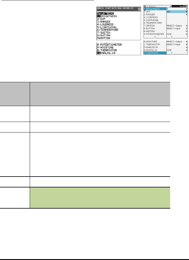
60 TI-Innovator™ Hub Commands version 1.2
READ
The READ command generates responses based on what is being requested.
Tells the Innovator to obtain data from the specified sensor, control, port, pin, or status
information including the setup of the hub, such as flow control, error settings, etc.
Must be followed by a Get() operation to receive the requested data.
TI-84 Plus CE TI-Nspire™ CX
BRIGHTNESS
Command: BRIGHTNESS
Command
Syntax:
READ BRIGHTNESS
Range:
Describe: Returns the current internal reading from the on-board ambient light
sensor.
Note the optional keywords of RANGE and AVERAGE can be appended to
the command to return the current RANGE setting for the BRIGHTNESS
sensor if set or the current AVERAGE value applied when reading the ADC
to obtain the reading.
READ BRIGHTNESS
Result: Read on-board light sensor level.
Type or
Addressable
Component:
Control

BRIGHTNESS AVERAGE
Command: BRIGHTNESS AVERAGE
Advanced user
Command
Syntax:
READ BRIGHTNESS.AVERAGE
Range:
Describe: Returns the current internal reading from the on-board ambient light
sensor.
Note the optional keywords of RANGE and AVERAGE can be appended to
the command to return the current RANGE setting for the BRIGHTNESS
sensor if set or the current AVERAGE value applied when reading the ADC
to obtain the reading.
READ BRIGHTNESS AVERAGE
Result: Read on-board light sensor level.
Type or
Addressable
Component:
Control
BRIGHTNESS RANGE
Command: BRIGHTNESS RANGE
Advanced user
Command
Syntax:
READ BRIGHTNESS.RANGE
Range:
Describe: Returns the current internal reading from the on-board ambient light
sensor.
Note the optional keywords of RANGE and AVERAGE can be appended to
the command to return the current RANGE setting for the BRIGHTNESS
sensor if set or the current AVERAGE value applied when reading the ADC
to obtain the reading.
READ BRIGHTNESS RANGE
Result: Read on-board light sensor level.
Type or
Addressable
Component:
Control
TI-Innovator™ Hub Commands version 1.2 61

62 TI-Innovator™ Hub Commands version 1.2
DHT i
Command: DHT i
Command
Syntax:
READ DHT i
Range: Temperature reading default is in Celsius
Humidity reading from 0 to 100 %
Describe: Returns a list consisting of the current temperature, humidity, type of
sensor, and last cached read status. The temperature and humidity can be
obtained by themselves by appending the TEMPERATURE or HUMIDITY
keywords to the end of the command. The type of sensor is indicated by a
1 for a DHT11, and a 2 for DHT22 style sensors. The status values are:
1=OK, 2=Timeout, 3=Checksum/bad reading.
READ DHT i – returns full cached information from last reading the DHT
task obtained.
READ DHT i TEMPERATURE – returns latest temperature reading.
READ DHT i HUMIDITY – returns latest humidity reading.
Result: Return list with current temperature in C, humidity in %, type(1=DHT11,
2=DHT22), and status (type/status only available in full list).
Where the status = 1:OK, =2:Timeout, =3:Checksum.
Type or
Addressable
Component:
Sensor
DHT i TEMPERATURE
Command: DHT i TEMPERATURE
Command
Syntax:
READ DHT i TEMPERATURE
Range: Temperature reading default is in Celsius
Humidity reading from 0 to 100 %
Describe: Returns a list consisting of the current temperature, humidity, type of
sensor, and last cached read status. The temperature and humidity can be
obtained by themselves by appending the TEMPERATURE or HUMIDITY
keywords to the end of the command. The type of sensor is indicated by a
1 for a DHT11, and a 2 for DHT22 style sensors. The status values are:
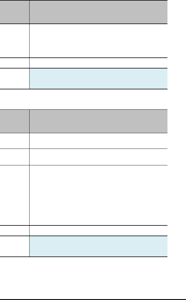
Command: DHT i TEMPERATURE
1=OK, 2=Timeout, 3=Checksum/bad reading.
READ DHT i – returns full cached information from last reading the DHT
task obtained.
READ DHT i TEMPERATURE – returns latest temperature reading.
READ DHT i HUMIDITY – returns latest humidity reading.
Result: Returns temperature component.
Type or
Addressable
Component:
Sensor
DHT i HUMIDITY
Command: DHT i HUMIDITY
Command
Syntax:
READ DHT i HUMIDITY
Range: Temperature reading default is in Celsius
Humidity reading from 0 to 100 %
Describe: Returns a list consisting of the current temperature, humidity, type of
sensor, and last cached read status. The temperature and humidity can be
obtained by themselves by appending the TEMPERATURE or HUMIDITY
keywords to the end of the command. The type of sensor is indicated by a
1 for a DHT11, and a 2 for DHT22 style sensors. The status values are:
1=OK, 2=Timeout, 3=Checksum/bad reading.
READ DHT i – returns full cached information from last reading the DHT
task obtained.
READ DHT i TEMPERATURE – returns latest temperature reading.
READ DHT i HUMIDITY – returns latest humidity reading.
Result: Returns humidity component.
Type or
Addressable
Component:
Sensor
TI-Innovator™ Hub Commands version 1.2 63
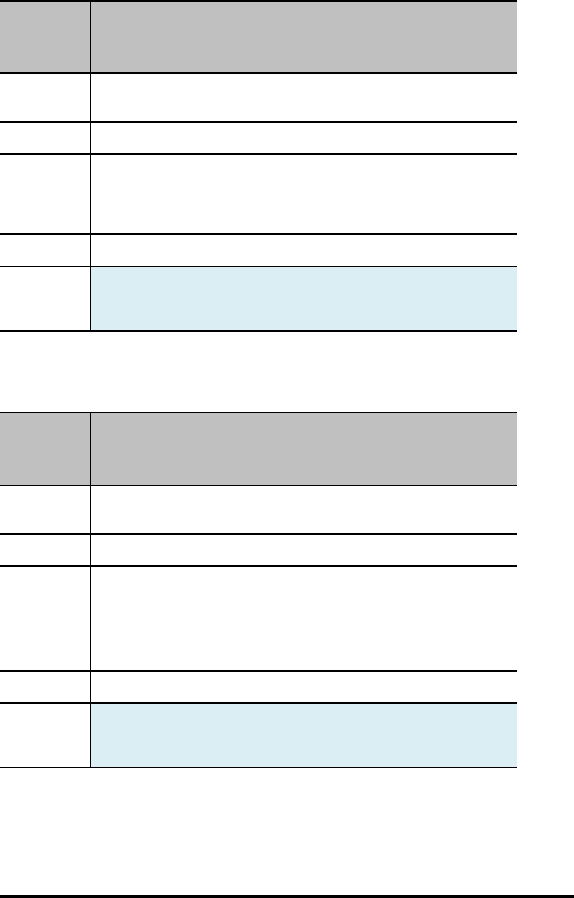
64 TI-Innovator™ Hub Commands version 1.2
RANGER i
Command: RANGER i
Command
Syntax:
READ RANGER i
Range:
Describe: Return the current distance measurement from the specified ultrasonic
ranging device; distance in meters. If no measurement is made due to the
distance being too far; a value of 0 will be returned. Valid measurements
are in +meters.
Result: Read distance in meters from distance sensor.
Type or
Addressable
Component:
Sensor
LOUDNESS i
Command: LOUDNESS i
Command
Syntax:
READ LOUDNESS i
Range:
Describe: Return the current analog level reported by the sound loudness level
sensor specified. Supports the AVERAGE and RANGE options.
READ LOUDNESS i
READ LOUDNESS i AVERAGE
READ LOUDNESS i RANGE
Result: Return level of sound detected by sound sensor.
Type or
Addressable
Component:
Sensor
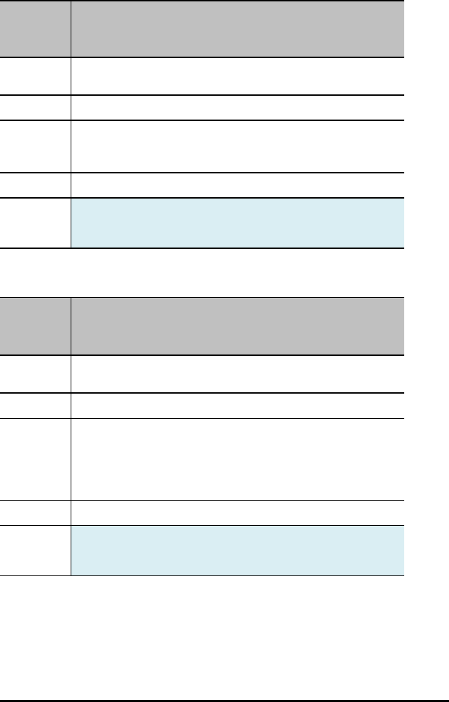
LOUDNESS i AVERAGE
Command: LOUDNESS i
Advanced user
Command
Syntax:
READ LOUDNESS i AVERAGE
Range:
Describe: Return the current analog level reported by the sound loudness level
sensor specified. Supports the AVERAGE and RANGE options.
READ LOUDNESS i AVERAGE
Result: Return level of sound detected by sound sensor.
Type or
Addressable
Component:
Sensor
LOUDNESS i RANGE
Command: LOUDNESS i RANGE
Advanced user
Command
Syntax:
READ LOUDNESS i.RANGE
Range:
Describe: Return the current analog level reported by the sound loudness level
sensor specified. Supports the AVERAGE and RANGE options.
READ LOUDNESS i
READ LOUDNESS i AVERAGE
READ LOUDNESS i RANGE
Result: Return level of sound detected by sound sensor.
Type or
Addressable
Component:
Sensor
TI-Innovator™ Hub Commands version 1.2 65

66 TI-Innovator™ Hub Commands version 1.2
LIGHTLEVEL i
Command: LIGHTLEVEL i
Command
Syntax:
READ LIGHTLEVEL i
Range: An integer value between 0 and 16383 (14 bit resolution)
Describe: Returns the current ADC value from the specified external light sensor.
External light sensors may be analog, or I2C (BH1750FVI I2C Light
sensor). When an analog sensor is present, it is generally assumed to be a
photodiode.
Additionally, the light level sensor may have AVERAGE and/or RANGE
values specified. These can be obtained by appending the AVERAGE or
RANGE keywords to the READ command.
READ LIGHTLEVEL i
READ LIGHTLEVEL i AVERAGE
READ LIGHTLEVEL i RANGE
Result: Read analog value of light sensor (uses averaging), or I2C (value in LUX
returned).
Type or
Addressable
Component:
Sensor
LIGHTLEVEL i AVERAGE
Command: LIGHTLEVEL i AVERAGE
Advanced user
Command
Syntax:
READ LIGHTLEVEL i AVERAGE
Range: An integer value between 0 and 16383 (14 bit resolution)
Describe: Returns the current ADC value from the specified external light sensor.
External light sensors may be analog, or I2C (BH1750FVI I2C Light
sensor). When an analog sensor is present, it is generally assumed to be a
photodiode.
Additionally, the light level sensor may have AVERAGE and/or RANGE
values specified. These can be obtained by appending the AVERAGE or
RANGE keywords to the READ command.
READ LIGHTLEVEL i AVERAGE
Result: Read analog value of light sensor (uses averaging), or I2C (value in LUX

Command: LIGHTLEVEL i AVERAGE
Advanced user
returned).
Type or
Addressable
Component:
Sensor
LIGHTLEVEL i RANGE
Command: LIGHTLEVEL i RANGE
Advanced user
Command
Syntax:
READ LIGHTLEVEL i RANGE
Range: An integer value between 0 and 16383 (14 bit resolution)
Describe: Returns the current ADC value from the specified external light sensor.
External light sensors may be analog, or I2C (BH1750FVI I2C Light
sensor). When an analog sensor is present, it is generally assumed to be a
photodiode.
Additionally, the light level sensor may have AVERAGE and/or RANGE
values specified. These can be obtained by appending the AVERAGE or
RANGE keywords to the READ command.
READ LIGHTLEVEL i RANGE
Result: Read analog value of light sensor (uses averaging), or I2C (value in LUX
returned).
Type or
Addressable
Component:
Sensor
TEMPERATURE i
Command: TEMPERATURE i
Command
Syntax:
READ TEMPERATURE i
TI-Innovator™ Hub Commands version 1.2 67
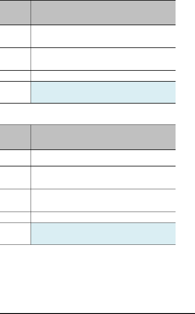
68 TI-Innovator™ Hub Commands version 1.2
Command: TEMPERATURE i
Range: Temperature reading default is in Celsius. The range depends on the
specific temperature sensor being used.
Humidity reading from 0 to 100 %
Describe: Returns the current temperature reading from the associated
temperature sensor. The temperature is given, by default, in Celsius.
READ TEMPERATURE i
Result: Return current temperature reading in Celsius.
Type or
Addressable
Component:
Sensor
TEMPERATURE i AVERAGE
Command: TEMPERATURE i AVERAGE
Advanced user
Command
Syntax:
READ TEMPERATURE i AVERAGE
Range: Temperature reading default is in Celsius. The range depends on the
specific temperature sensor being used.
Humidity reading from 0 to 100 %
Describe: Returns the current temperature reading from the associated
temperature sensor. The temperature is given, by default, in Celsius.
READ TEMPERATURE i AVERAGE
Result: Return current temperature reading in Celsius.
Type or
Addressable
Component:
Sensor

TEMPERATURE i CALIBRATION
Command: TEMPERATURE i CALIBRATION
Advanced user
Command
Syntax:
READ TEMPERATURE i CALIBRATION
Range: Temperature reading default is in Celsius. The range depends on the
specific temperature sensor being used.
Humidity reading from 0 to 100 %
Describe: Returns the current temperature reading from the associated
temperature sensor. The temperature is given, by default, in Celsius.
Result: Returns list with current {c1,c2,c3,r} values used for connected analog
temperature sensor.
Type or
Addressable
Component:
Sensor
SWITCH i
Command: SWITCH i
Command
Syntax:
READ SWITCH i
Range:
Describe: Returns the current state of the associated switch. If the switch is
connected, a value of 1 is returned. Not connected returns a value of 0. If
the switch was connected since the last reading, but is no longer
connected, a value of 2 is returned.
READ SWITCH i
Result: Returns state of switch (same status as BUTTON object, 0=not pressed,
1=pressed, 2=was pressed).
Type or
Addressable
Component:
Sensor
TI-Innovator™ Hub Commands version 1.2 69
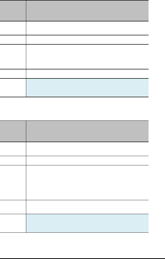
70 TI-Innovator™ Hub Commands version 1.2
BUTTON i
Command: BUTTON i
Command
Syntax:
READ BUTTON i
Range:
Describe: Reads the current cached state of the button.
A return value of 0 = not pressed, 1 = currently pressed, 2 = was pressed
and released since the last reading.
READ BUTTON i
Result: Read state of button/switch n - 0=not pressed, 1=pressed, 2=was pressed.
Type or
Addressable
Component:
Sensor
MOTION i
Command: MOTION i
Command
Syntax:
READ MOTION i
Range:
Describe: Return the current PIR Motion sensor information. PIR Motion sensors
are digital in nature, so are treated similar to a button in that the value
returned indicates motion presence or not.
0=no motion detected.
1=motion detected.
2=motion was detected.
Result: Read state of PIR Motion detector - 0=no motion, 1=motion, 2=motion
was detected but none now.
Type or
Addressable
Component:
Sensor
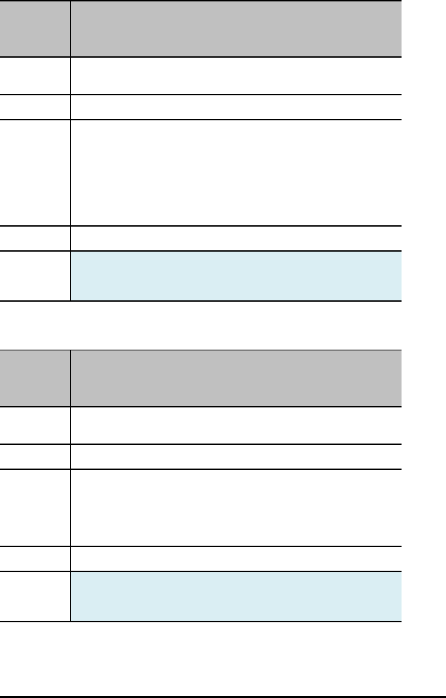
POTENTIOMETER i
Command: POTENTIOMETER i
Command
Syntax:
READ POTENTIOMETER i
Range:
Describe: Read analog value of the potentiometer (linear or rotary). The optional
AVERAGE and RANGE keywords can be appended to the command to
obtain the current average count, or mapped range being used, if present,
for the given potentiometer.
READ POTENTIOMETER i
READ POTENTIOMETER i RANGE
READ POTENTIOMETER i AVERAGE
Result: Read analog value of rotary encoder / potentiometer (uses averaging).
Type or
Addressable
Component:
Sensor
POTENTIOMETER i AVERAGE
Command: POTENTIOMETER i AVERAGE
Advanced user
Command
Syntax:
READ POTENTIOMETER i AVERAGE
Range:
Describe: Read analog value of the potentiometer (linear or rotary). The optional
AVERAGE and RANGE keywords can be appended to the command to
obtain the current average count, or mapped range being used, if present,
for the given potentiometer.
READ POTENTIOMETER i AVERAGE
Result: Read analog value of rotary encoder / potentiometer (uses averaging).
Type or
Addressable
Component:
Sensor
TI-Innovator™ Hub Commands version 1.2 71
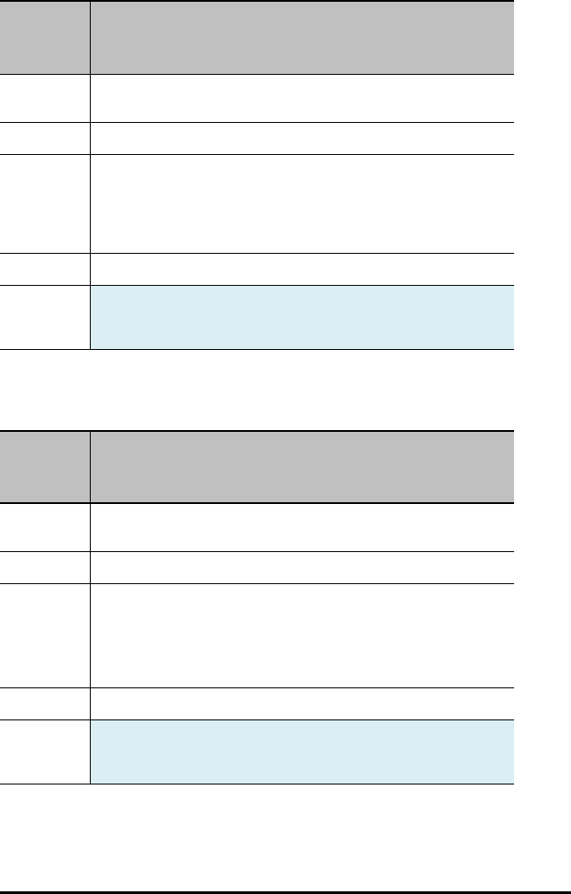
72 TI-Innovator™ Hub Commands version 1.2
POTENTIOMETER i RANGE
Command: POTENTIOMETER i RANGE
Advanced user
Command
Syntax:
READ POTENTIOMETER i RANGE
Range:
Describe: Read analog value of the potentiometer (linear or rotary). The optional
AVERAGE and RANGE keywords can be appended to the command to
obtain the current average count, or mapped range being used, if present,
for the given potentiometer.
READ POTENTIOMETER i RANGE
Result: Read analog value of rotary encoder / potentiometer (uses averaging).
Type or
Addressable
Component:
Sensor
MOISTURE i
Command: MOISTURE i
Command
Syntax:
READ MOISTURE i
Range: An integer value between 0 and 16383 (14 bit resolution)
Describe: Return the current analog level reported by the moisture sensor specified.
Supports the AVERAGE and RANGE options.
READ MOISTURE i
READ MOISTURE i AVERAGE
READ MOISTURE i RANGE
Result: Read analog value of moisture sensor (uses averaging).
Type or
Addressable
Component:
Sensor
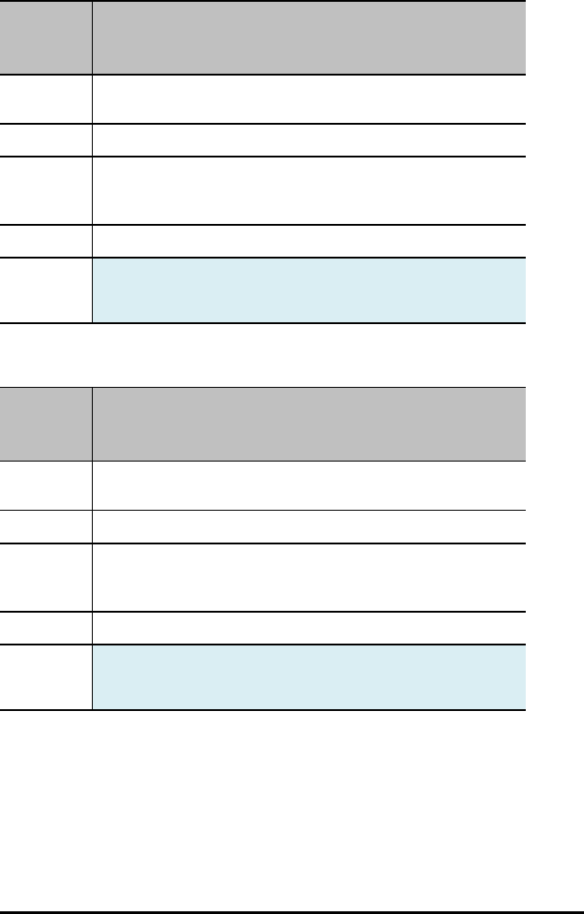
MOISTURE i AVERAGE
Command: MOISTURE i AVERAGE
Advanced user
Command
Syntax:
READ MOISTURE i AVERAGE
Range:
Describe: Return the current analog level reported by the moisture sensor specified.
Supports the AVERAGE and RANGE options.
READ MOISTURE i AVERAGE
Result: Read analog value of moisture sensor (uses averaging).
Type or
Addressable
Component:
Sensor
MOISTURE i RANGE
Command: MOISTURE i RANGE
Command
Syntax:
READ MOISTURE i RANGE
Range:
Describe: Return the current analog level reported by the moisture sensor specified.
Supports the AVERAGE and RANGE options.
READ MOISTURE i RANGE
Result: Read analog value of moisture sensor (uses averaging).
Type or
Addressable
Component:
Sensor
TI-Innovator™ Hub Commands version 1.2 73

74 TI-Innovator™ Hub Commands version 1.2
THERMISTOR i
Command: THERMISTORi
Command
Syntax:
READ THERMISTOR i
Range:
Describe: Returns the current temperature reading from the associated thermistor
sensor. Temperature is returned in Celsius.
Result: Return current thermistor temperature in Celsius.
Type or
Addressable
Component:
Sensor
THERMISTOR i AVERAGE
Command: THERMISTORi AVERAGE
Advanced user
Command
Syntax:
READ THERMISTOR i AVERAGE
Range:
Describe: Returns the current temperature reading from the associated thermistor
sensor. Temperature is returned in Celsius.
Result: Return current thermistor temperature in Celsius.
Type or
Addressable
Component:
Sensor
THERMISTOR i CALIBRATION
Command: THERMISTOR i CALIBRATION
Advanced user
Command READ THERMISTOR i CALIBRATION

Command: THERMISTOR i CALIBRATION
Advanced user
Syntax:
Range:
Describe: Returns the current temperature reading from the associated thermistor
sensor. Temperature is returned in Celsius.
Result: Returns list with current {c1,c2,c3,r} values used for connected thermistor.
Type or
Addressable
Component:
Sensor
ANALOG.IN i
Command: ANALOG.IN i
Command
Syntax:
READ.ANALOG.IN i
Range:
Describe: Generic analog input sensor.
READ ANALOG.IN i – will return the ADC reading on the analog input
associated with the object.
Result: Reads generic ANALOG.IN input object
Type or
Addressable
Component:
Sensor
ANALOG.IN i AVERAGE
Command: ANALOG.IN i AVERAGE
Advanced user
Command
Syntax:
READ.ANALOG.IN i AVERAGE
TI-Innovator™ Hub Commands version 1.2 75
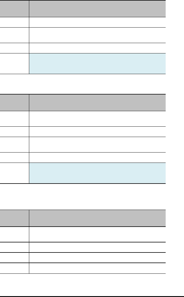
76 TI-Innovator™ Hub Commands version 1.2
Command: ANALOG.IN i AVERAGE
Advanced user
Range:
Describe: READ ANALOG IN i AVERAGE – gets the current averaging value for the
object.
Result: Reads generic ANALOG.IN input object
Type or
Addressable
Component:
Sensor
ANALOG.IN i RANGE
Command: ANALOG.IN i RANGE
Advanced user
Command
Syntax:
READ.ANALOG.IN i RANGE
Range:
Describe: READ ANALOG IN i RANGE – returns the upper and lower range values
associated with the object if specified, or error otherwise
Result: Reads generic ANALOG.IN input object
Type or
Addressable
Component:
Sensor
ANALOG.OUT i
Command: ANALOG.OUT i
Command
Syntax:
READ ANALOG.OUT i
Range:
Describe: Returns current PWM duty cycle if the output is on, or 0 if not on.
Result: Reads current PWM duty cycle on pin, 0 if none.

Command: ANALOG.OUT i
Type or
Addressable
Component:
Control
DIGITAL.IN i
Command: DIGITAL.IN i
Command
Syntax:
READ DIGITAL.IN i
Range:
Describe: Returns the current state of the digital pin connected to the DIGITAL
object, or the cached state of the digital output value last SET to the object.
Result: Return 0 (low), 1 (high).
Type or
Addressable
Component:
Control/Sensor
AVERAGING
Command: AVERAGING
Advanced user
Command
Syntax:
READ AVERAGING
Range:
Describe: Returns the current global setting for the analog averaging default value.
Result: Return current oversampling/averaging count for sampling analog inputs
(this is the GLOBAL default value currently in use).
Type or
Addressable
Component:
Setting
TI-Innovator™ Hub Commands version 1.2 77

78 TI-Innovator™ Hub Commands version 1.2
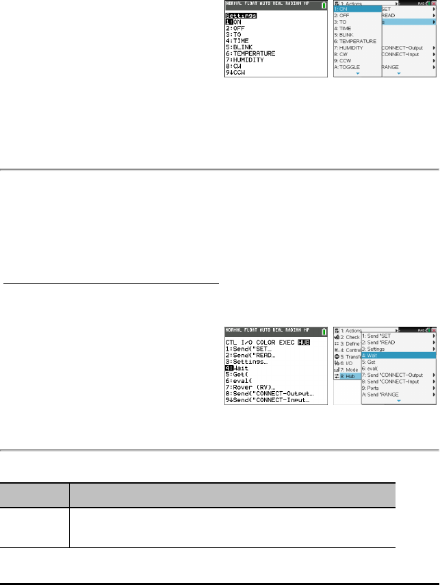
Settings
Settings menu contains operations to set the state of digital and analog pin operations
such as the LED in the TI-Innovator™ Hub or a connected servo motor movement to
states such as ON, OFF, CW (clockwise), and CCW (counterclockwise).
– 1: ON
– 2: OFF
– 3: TO
– 4: TIME
– 5: BLINK
– 6: TEMPERATURE
– 7: HUMIDITY
– 8: CW
– 9: CCW
– 0: TOGGLE
TI-84 Plus CE
See : TI-84 Plus CE
Programming
TI-Nspire™ CX
See: TI-Nspire™ CX
Programming
Wait
Wait suspends execution of a program for a given time. Maximum time is 100 seconds.
During the wait time, the busy indicator is on in the top-right corner of the screen.
Wait may be used in TI-Innovator™ Hub programs to allow time for sensor or control
communications prior to the program executing the next command line.
TI-84 Plus CE
See: TI-84 Plus CE
Programming
TI-Nspire™ CX
See: TI-Nspire™ CX
Programming
Wait
Command: Wait
Command
Syntax:
Wait timeInSeconds
Suspends execution for a period of timeInSeconds seconds.
TI-Innovator™ Hub Commands version 1.2 79
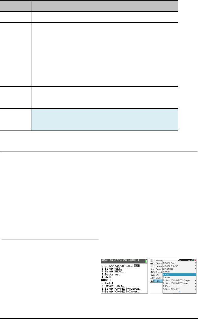
80 TI-Innovator™ Hub Commands version 1.2
Command: Wait
Range 0 through 100
Describe: Wait may be used in TI-Innovator™ Hub programs to allow time for
sensor or control communications prior to the program executing the
next command line.
Wait is particularly useful in a program that needs a brief delay to allow
requested data to become available.
The argument timeInSeconds must be an expression that simplifies to a
decimal value in the range 0 through 100. The command rounds this value
up to the nearest 0.1 seconds.
Note: You can use the Wait command within a user-defined program but
not within a function.
Result: Wait suspends execution of a program for a given time. Maximum time is
100 seconds. During the wait time, the busy indicator is on in the top-right
corner of the screen.
Type or
Addressable
Component:
Not Applicable
Get(
Get( Retrieves a value from a connected TI-Innovator™ Hub and stores the data to a
variable on the receiving CE calculator.
TI-84 Plus CE
Get( command definition is specific to the TI-8x calculator and the cable connection via
DBus or USB. The CE calculator is USB connectivity only and here, Get( is designed for
communication with the TI-Innovator™ Hub.
TI-Nspire™ CX
TI-84 Plus CE
See: TI-84 Plus CE
Programming
TI-Nspire™ CX
See: TI-Nspire™ CX
Programming

Get(
Command: Get(
Command
Syntax:
TI-84 Plus CE:
Get(variable)
TI-Nspire™ CX platform:
Get [promptString,] var[, statusVar]
Get [promptString,] func(arg1, ...argn) [, statusVar]
Range
Describe:
Result: Programming command: Retrieves a value from a connected TI-
Innovator™ Hub and assigns the value to variable var.
The value must be requested:
• In advance, through a Send "READ ..." command.
— or —
• By embedding a "READ ..." request as the optional
promptString argument. This method lets you use a single
command to request the value and retrieve it. (TI-Nspire™
CX platform only).
Implicit simplification takes place. For example, a received string of "123"
is interpreted as a numeric value.
The information below applies only on the TI-Nspire CX platform:
To preserve the string, use GetStr instead of Get.
If you include the optional argument statusVar, it is assigned a value
based on the success of the operation. A value of zero means that no data
was received.
In the second syntax, the func() argument allows a program to store the
received string as a function definition. This syntax operates as if the
program executed the command:
Define func(arg1, ...argn) = received string
The program can then use the defined function func().
Note: You can use the Get command within a user-defined program but
not within a function.
Type or
Addressable
Component:
All input devices.
TI-Innovator™ Hub Commands version 1.2 81
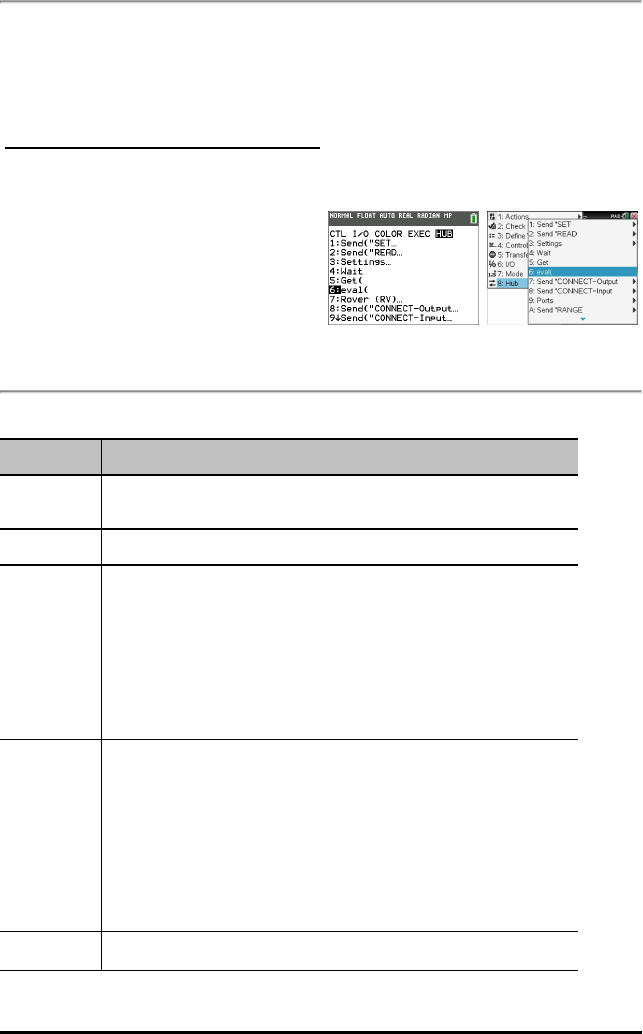
82 TI-Innovator™ Hub Commands version 1.2
eval(
The software evaluates expression Expr and replaces the eval() statement with the
result as a character string.
The argument Expr must simplify to a real number.
TI-84 Plus CE
See: TI-84 Plus CE
Programming
TI-Nspire™ CX
See: TI-Nspire™ CX
Programming
eval(
Command: eval(
Command
Syntax:
eval(Expr)⇒string
Range
Describe: The software evaluates expression Expr and replaces the eval() statement
with the result as a character string.
The argument Expr must simplify to a real number.
TI-84 Plus CE:eval() can be used as a standalone command outside a TI-
Innovator™ Hub command.
TI-Nspire™ CX platform: eval() is valid only in the TI-Innovator™ Hub
Command argument of programming commands Get,GetStr, and Send.
Result: TI-84 Plus CE: For debugging purposes, using the command line Disp Ans
immediately after a command line using Send(displays the complete string
being sent.
TI-Nspire™ CX platform: Although eval() does not display its result, you
can view the resulting Hub command string after executing the command
by inspecting any of the following special variables.
iostr.SendAns
iostr.GetAns
iostr.GetStrAns
Type or Not Applicable

Command: eval(
Addressable
Component:
TI-Innovator™ Hub Commands version 1.2 83


Drive RV...
RV Drive Command Families
• Base Drive Commands (in the spirit of Turtle Graphics)
- FORWARD, BACKWARD, RIGHT, LEFT, STOP, STAY
• Math Coordinate Drive Commands
- Turn to Angle
Note: Drive commands have options for Speed, Time and Distance as appropriate
• See RV Settings for Machine-Level Control Commands
- Set Left and Right Motor values for direction (CW/CCW) and level (0-255,Coast)
- Read accumulated values for wheel encoder edges and gyro heading change.
•Drive RV…
– Send("RV
–FORWARD
–BACKWARD
–LEFT
–RIGHT
–STOP
–RESUME
–STAY
–TO XY (INACTIVE in v1.2
Release)
–TO POLAR (INACTIVE in v1.2
Release)
–TO ANGLE
TI-84 PlusCE TI-Nspire™ CX
TI-Innovator™ Hub Commands version 1.2 85
86 TI-Innovator™ Hub Commands version 1.2
RV FORWARD
Command: RV FORWARD
Command
Syntax:
RV FORWARD [[SPEED s] [DISTANCE d] [TIME t]]
Code
Samples:
Send ("RV FORWARD 0.5 M")
Send ("RV FORWARD SPEED 0.22 M/S TIME 10")
[SET] RV FORWARD
[SET] RV FORWARD [DISTANCE] d [M|UNIT|REV]
[SET] RV FORWARD [DISTANCE] d [M|UNIT|REV]
SPEED s.ss [M/S|[UNIT/S]|REV/S]
[SET] RV FORWARD [DISTANCE] d [M|UNIT|REV]
TIME t
[SET] RV FORWARD SPEED s [M/S|UNIT/S|REV/S]
[TIME t]
[SET] RV FORWARD TIME t [SPEED s.ss
[M/S|[UNIT/S]|REV/S]]
Range: N/A
Describe: RV moves forward a given distance (default 0.75 m). Default distance if
specified is in UNIT (grid units). Optional M=meters, UNIT=grid-unit,
REV=wheel-revolution.
Default speed is 0.20 m/sec, max is 0.23 m/sec, min is 0.14 m/sec.
Speed may be given and specified in meters/second, unit/second,
revolutions/second.
Result: Action to make the RV move in a forward direction
Type or
Addressable
Component:
Control
Note: This Rover control command is sent and executed in a queue.
RV BACKWARD
Command: RV BACKWARD
Command
Syntax:
RV BACKWARD
Code
Sample:
Send("RV BACKWARD 0.5 M")
Send("RV BACKWARD SPEED 0.22 M/S TIME 10")
[SET] RV BACKWARD
[SET] RV BACKWARD [DISTANCE] d [M|UNIT|REV]
[SET] RV BACKWARD [DISTANCE] d [M|UNIT|REV]
SPEED s.ss [M/S|[UNIT/S]|REV/S]
[SET] RV BACKWARD [DISTANCE] d [M|UNIT|REV]
TIME t
[SET] RV BACKWARD SPEED s.ss
[M/S|UNIT/S|REV/S] [TIME t]
[SET] RV BACKWARD TIME t
[SPEED s.ss [M/S|UNIT/S|REV/S]]
Range: N/A
Describe: RV moves backward a given distance (default 0.75 m). Default distance if
specified is in UNIT (grid units). Optional M=meters, UNIT=grid-unit,
REV=wheel-revolution.
Default speed is 0.20 m/sec, max is 0.23 m/sec, min is 0.14 m/sec.
Speed may be given and specified in meters/second, unit/second,
revolutions/second.
Result: Action to make the RV move in a backward direction.
Type or
Addressable
Component:
Control
Note: This Rover control command is sent and executed in a queue.
TI-Innovator™ Hub Commands version 1.2 87

88 TI-Innovator™ Hub Commands version 1.2
RV LEFT
Command: RV LEFT
Command
Syntax:
RV LEFT
Code
Sample:
Send "RV LEFT"
[SET] RV LEFT [ddd [DEGREES]]
[SET] RV LEFT [rrr RADIANS]
[SET] RV LEFT [ggg GRADIANS]
Range: N/A
Describe: Default turn is 90 degrees unless DEGREES, RADIANS, or GRADIANS
keyword is present, and then the value is converted internally to degrees
format from the specified units. Value given is ranged to a value between
0.0 and 360.0 degrees. The turn will be executed as a SPIN motion.
Result: Turn Rover to the LEFT.
Type or
Addressable
Component:
Control
Note: This Rover control command is sent and executed in a queue.
RV RIGHT
Command: RV RIGHT
Command
Syntax:
RV RIGHT
Code
Sample:
Send "RV RIGHT"
[SET] RV RIGHT [ddd [DEGREES]]
[SET] RV RIGHT [rrr RADIANS]
[SET] RV RIGHT [ggg GRADIANS]
Range: N/A
Describe: Default turn is 90 degrees unless DEGREES, RADIANS, or GRADIANS
keyword is present, and then the value is converted internally to degrees
format from the specified units. Value given is ranged to a value between
0.0 and 360.0 degrees. The turn will be executed as a SPIN motion.
Result: Turn Rover to the RIGHT.
Type or Control

Command: RV RIGHT
Addressable
Component:
Note: This Rover control command is sent and executed in a queue.
RV STOP
Command: RV STOP
Command
Syntax:
RV STOP
Code
Sample:
Send "RV STOP"
[SET] RV STOP
[SET] RV STOP CLEAR
Range: N/A
Describe: The RV will stop any current movement immediately. That movement can
be resumed from where it left off with a RESUME operation. Any
movement commands will cause the queue to flush immediately, and begin
the just-posted new movement operation
Result: Stop processing Rover commands from the command queue, and leave
pending operations in the queue. (immediate action). Queue can be
resumed by RESUME.The RV will stop any current movement
immediately. That movement can be resumed from where it left off with a
RESUME operation. Any movement commands will cause the queue to
flush immediately, and begin the just-posted new movement operation.
Stop processing Rover commands from the command queue, and flush
any pending operations left in the queue. (immediate action).
Type or
Addressable
Component:
Control
Note: This Rover control command is executed immediately.
RV RESUME
Command: RV RESUME
Command
Syntax:
RV RESUME
TI-Innovator™ Hub Commands version 1.2 89

90 TI-Innovator™ Hub Commands version 1.2
Command: RV RESUME
Code
Sample:
Send "RV RESUME"
[SET] RV RESUME
Range: N/A
Describe: Enable processing of Rover commands from the command queue.
(immediate action), or resume (see RV STAY) operation.
Result: Resume operation.
Type or
Addressable
Component:
Control
Note: This Rover control command is sent and executed in a queue.
RV STAY
Command: RV STAY
Command
Syntax:
RV STAY
Code
Sample:
Send "RV STAY"
[SET] RV STAY [[TIME] s.ss]
Range: N/A
Describe: Tells RV to "stay" in place for an optionally specified amount of time in
seconds.
Default is 30.0 seconds.
Result: RV stays in position.
Type or
Addressable
Component:
Control
Note: This Rover control command is sent and executed in a queue.
RV TO XY (INACTIVE in v1.2 Release)
RV TO POLAR (INACTIVE in v1.2 Release)

RV TO ANGLE
Command: RV TO ANGLE
Command
Syntax:
RV TO ANGLE
Code
Sample:
Send "RV TO ANGLE"
[SET] RV TO ANGLE rr.rr
[[DEGREES]|RADIANS|GRADIANS]
Range: N/A
Describe:
Result: Spins the RV to the specified angle from current heading.
Type or
Addressable
Component:
Control
Note: This Rover control command is sent and executed in a queue.
TI-Innovator™ Hub Commands version 1.2 91
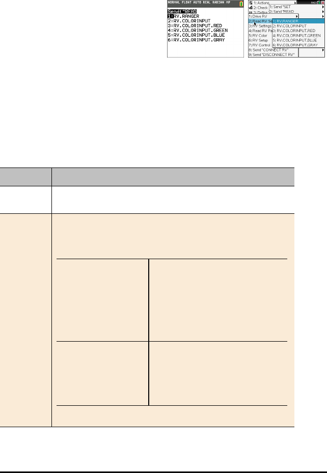
92 TI-Innovator™ Hub Commands version 1.2
READ RV Sensors...
SEND("Read Sensor Commands
• Reading of low level sensors for learning foundations of robotics.
•Read RV Sensors…
– Send("READ
–RV.RANGER
–RV.COLORINPUT
–RV.COLORINPUT.RED
–RV.COLORINPUT.GREEN
–RV.COLORINPUT.BLUE
–RV.COLORINPUT.GRAY
•RV.RANGER: Returns value in Meters.
•RV.COLORINPUT: Reads color sensor
that is built into the RV.
RV.RANGER
Command: RV.RANGER
Command
Syntax:
RV.RANGER
Code
Sample:
Send("READ RV.RANGER")
Get(R)
Connects the Rover
Vehicle to the TI-
Innovator™ Hub. This
establishes connections
with the motor driver,
color sensor, gyroscope,
ultrasonic ranger, and
proximity sensors.
CONNECT RV
Returns the current
distance from the front of
the RV to an obstacle. If
there is no obstacle
detected, a range of
10.00 meters is reported
READ RV.RANGER
Get(R)

Command: RV.RANGER
Range: N/A
Describe: The front-facing ultrasonic distance sensor. Returns measurements in
meters. ~10.00 meters means no obstacle was detected.
Result: Returns value in Meters.
Type or
Addressable
Component:
Sensor
Note: This Rover sensor command is executed immediately.
RV.COLORINPUT
Command: RV.COLORINPUT
Command
Syntax:
RV.COLORINPUT
Code
Sample:
Send("READ RV.COLORINPUT")
Get(C)
Range: 1 thru 9
Describe: Bottom-mounted color sensor detects the color of the surface. Can also
detect gray-level scale of black (0) to white (255).
Result: Returns current color sensor information.
The return value is in the 1 – 9 range which maps to the colors below:
Color Return value
Red 1
Green 2
Blue 3
Cyan 4
Magenta 5
Yellow 6
Black 7
White 8
Gray 9
Type or
Addressable
Component:
Sensor
Note: This Rover sensor command is executed immediately.
TI-Innovator™ Hub Commands version 1.2 93

94 TI-Innovator™ Hub Commands version 1.2
RV.COLORINPUT.RED
Command: RV.COLORINPUT.RED
Command
Syntax:
RV.COLORINPUT.RED
Code
Sample:
Send("READ RV.COLORINPUT.RED")
Get(R)
Range: 0 - 255
Describe: Detect intensity of individual red components of surface.
The results are in 0-255 range.
Result: Returns current color sensor "red value".
Type or
Addressable
Component:
Sensor
Note: This Rover sensor command is executed immediately.
RV.COLORINPUT.GREEN
Command: RV.COLORINPUT.GREEN
Command
Syntax:
RV.COLORINPUT.GREEN
Code
Sample:
Send("READ RV.COLORINPUT.GREEN")
Get(G)
Range: 0 - 255
Describe: Detect intensity of individual green components of surface.
The results are in 0-255 range.
Result: Returns current color sensor "green" value.
Type or
Addressable
Component:
Sensor
Note: This Rover sensor command is executed immediately.
RV.COLORINPUT.BLUE
Command: RV.COLORINPUT.BLUE
Command
Syntax:
RV.COLORINPUT.BLUE
Code
Sample:
Send("READ RV.COLORINPUT.BLUE")
Get(B)
Range: 0 - 255
Describe: Detect intensity of individual blue components of surface.
The results are in 0-255 range.
Result: Returns current color sensor "blue" value.
Type or
Addressable
Component:
Sensor
Note: This Rover sensor command is executed immediately.
RV.COLORINPUT.GRAY
Command: RV.COLORINPUT.GRAY
Command
Syntax:
RV.COLORINPUT.GRAY
Code
Sample:
Send("READ RV.COLORINPUT.GRAY")
Get(G)
Range: 0 - 255
Describe: Detect grayness of surface.
The result will be in 0-255 range.
Result: Returns an interpolated "grayscale" value based on 0.3*red + 0.59*green
+ 0.11*blue
0-black, 255 - white.
Type or
Addressable
Component:
Sensor
Note: This Rover sensor command is executed immediately.
TI-Innovator™ Hub Commands version 1.2 95
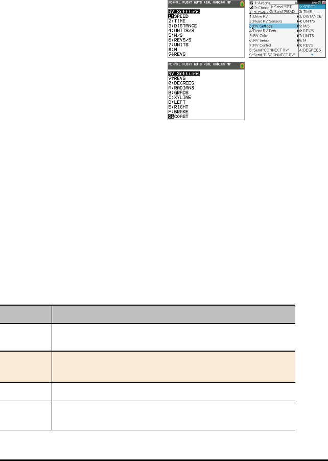
96 TI-Innovator™ Hub Commands version 1.2
RV Settings...
RV Settings Commands
Settings menu for Rover contains other commands that support RV commands such as
FORWARD or BACKWARD.
•RV Settings...
– RV Settings
– SPEED
– TIME
– DISTANCE
– UNIT/S
– M/S
– REV/S
– UNITS
– M
– REVS
– DEGREES
– RADIANS
– GRADS
– XYLINE
– LEFT
– RIGHT
– BRAKE
– COAST
– CW
– CCW
SPEED
Command: SPEED
Command
Syntax:
SPEED
Code
Sample:
SPEED
Range: N/A
Describe: Speed may be given (default is 0.20 m/sec, max is 0.23 m/sec, min is 0.14
m/sec) and specified in meters/second, unit/second, revolutions/second,
Command: SPEED
or feet/second.
Result:
Type or
Addressable
Component:
Setting
TIME
Command: TIME
Command Syntax: TIME
Code
Sample:
TIME
Range: N/A
Describe: .
Result:
Type or
Addressable Component:
Setting
DEGREES
Command: DISTANCE
Command Syntax: DISTANCE
Code
Sample:
DISTANCE
Range: N/A
Describe:
Result:
Type or
Addressable Component:
Setting
TI-Innovator™ Hub Commands version 1.2 97

98 TI-Innovator™ Hub Commands version 1.2
UNIT/S
Command: UNIT/S
Command Syntax: UNIT/S
Code
Sample:
UNIT/S
Range: N/A
Describe:
Result:
Type or
Addressable Component:
Setting
M/S
Command: M/S
Command Syntax: M/S
Code
Sample:
M/S
Range: N/A
Describe:
Result:
Type or
Addressable Component:
Setting
REV/S
Command: REV/S
Command Syntax: REV/S
Code
Sample:
REV/S
Command: REV/S
Range: N/A
Describe:
Result:
Type or
Addressable Component:
Setting
UNITS
Command: UNITS
Command Syntax: UNITS
Code
Sample:
UNITS
Range: N/A
Describe:
Result:
Type or
Addressable Component:
Setting
M
Command: M
Command Syntax: M
Code
Sample:
M
Range: N/A
Describe:
Result:
Type or
Addressable Component:
Setting
TI-Innovator™ Hub Commands version 1.2 99

100 TI-Innovator™ Hub Commands version 1.2
REVS
Command: REVS
Command Syntax: REVS
Code
Sample:
REVS
Range: N/A
Describe: Return list of wheel revolutions traveled.
Result:
Type or
Addressable Component:
Setting
DEGREES
Command: DEGREES
Command Syntax: DEGREES
Code
Sample:
DEGREES
Range: N/A
Describe:
Result:
Type or
Addressable Component:
Setting
RADIANS
Command: RADIANS
Command Syntax: RADIANS
Code
Sample:
RADIANS

Command: RADIANS
Range: N/A
Describe:
Result:
Type or
Addressable Component:
Setting
GRADS
Command: GRADS
Command Syntax: GRADS
Code
Sample:
GRADS
Range: N/A
Describe:
Result:
Type or
Addressable Component:
Setting
XYLINE
Command: XYLINE
Command Syntax: XYLINE
Code
Sample:
XYLINE
Range: N/A
Describe:
Result:
Type or
Addressable Component:
Setting
TI-Innovator™ Hub Commands version 1.2 101
102 TI-Innovator™ Hub Commands version 1.2
LEFT
Command: LEFT
Command Syntax: LEFT
Code
Sample:
LEFT
Range: N/A
Describe:
Result:
Type or
Addressable Component:
Setting
RIGHT
Command: RIGHT
Command Syntax: RIGHT
Code
Sample:
RIGHT
Range: N/A
Describe:
Result:
Type or
Addressable Component:
Setting
BRAKE
Command: BRAKE
Command Syntax: BRAKE
Code
Sample:
BRAKE
Command: BRAKE
Range: N/A
Describe:
Result:
Type or
Addressable Component:
Setting
COAST
Command: COAST
Command Syntax: COAST
Code
Sample:
COAST
Range: N/A
Describe:
Result:
Type or
Addressable Component:
Setting
CW
Command: CW
Command
Syntax:
CW
Code
Sample:
CW
Range: N/A
Describe: CW.b (value is positive) = Wheel rotate clockwise, backward direction
CW.f (value is positive) = Wheel rotates clockwise, forward direction
CW.f (value is negative) = Wheel rotates clockwise, forward direction
TI-Innovator™ Hub Commands version 1.2 103
104 TI-Innovator™ Hub Commands version 1.2
Command: CW
Result:
Type or
Addressable
Component:
Setting
CCW
Command: CCW
Command
Syntax:
CCW
Code
Sample:
CCW
Range: N/A
Describe: CCW.f (value is positive) = Wheel rotates counter-clockwise, forward
direction
CCW.b (value is positive) = Wheel rotates counter-clockwise, backward
direction
CWW.b (value is negative) = Wheel rotates counter-clockwise, backward
direction
Result:
Type or
Addressable
Component:
Setting

Read RV Path…
Reading WAYPOINT and PATH
Tracking the RV’s Path
In order to support analysis of the Rover during and after a run, the sketch will
automatically measure the following information for each Drive command:
• X Coordinate on virtual grid
• Y Coordinate on virtual grid
• Time in seconds that the current command has been executing.
• Distance in coordinate units for the path segment.
• Heading in degrees (absolute terms measured Counter Clockwise with the X-axis as
0 degrees.
• Revolutions by the wheel in executing the current command
• Command number, tracks the number of commands executed, begins with 0.
The Path values will be stored in lists, starting with the segments associated with the
earliest commands and going to the segments associated with the latest commands.
The drive command in progress, the WAYPOINT, will repeatedly update the last
element in the Path lists as the Rover progresses toward the last waypoint.
When a drive command is completed a new waypoint is initiated and the dimension of
the Path lists are incremented.
Note: This implies that when all the drive commands in the queue are completed
that another waypoint for the stopped state is automatically started. This is similar
to the initial position where the RV is stationary and counting time.
Max number of waypoints: 80
TI-Innovator™ Hub Commands version 1.2 105
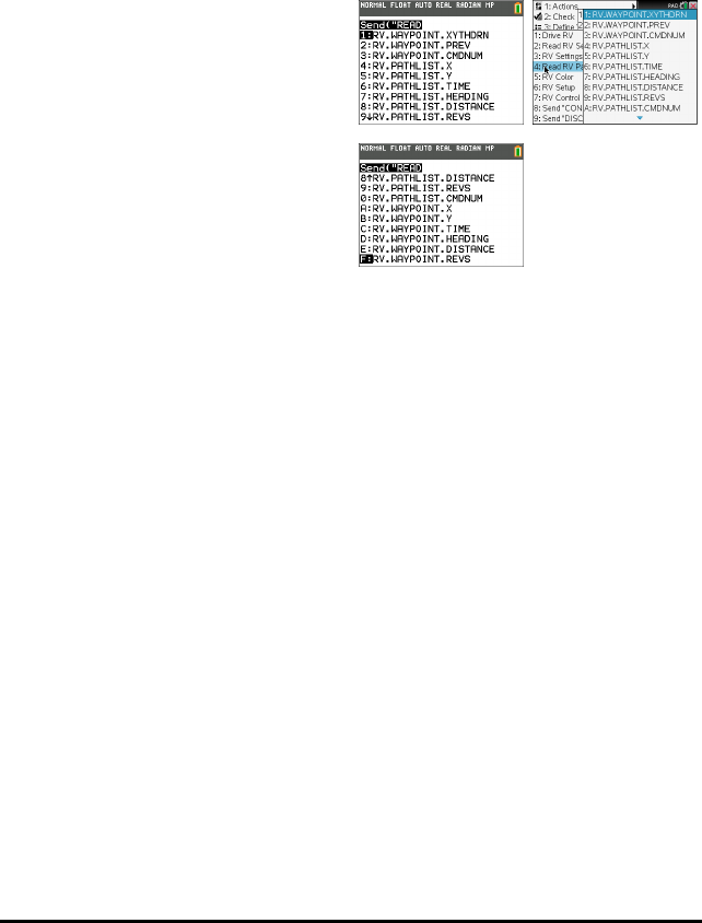
106 TI-Innovator™ Hub Commands version 1.2
RV Position and Path
• Ability to read X,Y coordinate, Heading, Time and Distance for each drive command
in execution.
• Will store path history in lists for plotting and analysis
Note: Coordinate grid scale can be set by the user, default is 10cm per unit. The user
will have options to set the origin of the grid.
•Read RV Path…
– Send("READ
–RV.WAYPOINT.XYTHDRN
–RV.WAYPOINT.PREV
–RV.WAYPOINT.CMDNUM
–RV.PATHLIST.X
–RV.PATHLIST.Y
–RV.PATHLIST.TIME
–RV.PATHLIST.HEADING
–RV.PATHLIST.DISTANCE
–RV.PATHLIST.REVS
–RV.PATHLIST.CMDNUM
–RV.WAYPOINT.X
–RV.WAYPOINT.Y
–RV.WAYPOINT.TIME
–RV.WAYPOINT.HEADING
–RV.WAYPOINT.DISTANCE
–RV.WAYPOINT.REVS
TI-84 PlusCE TI-Nspire™ CX

RV.WAYPOINT.XYTHDRN
Command: RV.WAYPOINT.XYTHDRN
Command
Syntax:
RV.WAYPOINT.XYTHDRN
Code
Sample:
Send("READ RV.WAYPOINT.XYTHDRN")
Example: Getting the distance traveled toward the current way-point from the last
way-point
Code
Sample:
Send("READ RV.WAYPOINT.XYTHDRN")
Get(L1)
(L1)(5)->D
Range: N/A
Describe: READ RV.WAYPOINT.XYTHDRN - read the x-coord, y-coord, time,
heading, distance traveled, number of wheel revolutions, command
number of the current waypoint. Returns a list with all these values as
elements.
Result: Return list of current way-point X, Y coordinates, Time, Heading, Distance,
Revolutions, and command number.
Type or
Addressable
Component:
Returns Data
RV.WAYPOINT.PREV
Command: RV.WAYPOINT.PREV
Command
Syntax:
RV.WAYPOINT.PREV
Code
Sample:
Send("READ RV.WAYPOINT.PREV")
Example: Getting the distance traveled during the previous way-point.
Code
Sample:
Send("READ RV.WAYPOINT.PREV")
Get(L1)
(L1)(5)->D
TI-Innovator™ Hub Commands version 1.2 107

108 TI-Innovator™ Hub Commands version 1.2
Command: RV.WAYPOINT.PREV
Range: N/A
Describe: READ RV.WAYPOINT.PREV - read the x-coord, y-coord, time, heading,
distance traveled, number of wheel revolutions, command number of the
previous waypoint. Returns a list with all these values as elements.
Result: Return list of the previous way-point X, Y coordinates, time, heading,
distance, revolutions, and command number.
Type or
Addressable
Component:
Returns Data
RV.WAYPOINT.CMDNUM
Command: RV.WAYPOINT.CMDNUM
Command
Syntax:
RV.WAYPOINT.CMDNUM
Code
Sample:
Send("READ RV.WAYPOINT.CMDNUM")
Example: Program to determine if a drive command has completed without
referring to a specific command number.
Note: the Wait is intended to increase the probability of catching a
difference in the Command Number.
Code
Sample:
Send("RV FORWARD 10")
Send("READ RV.WAYPOINT.CMDNUM")
Get(M)
M->N
While M=N
Send("READ RV.WAYPOINT.CMDNUM")
Get(N)
End
Disp "Drive Command is completed"
Range: N/A
Describe: READ RV.WAYPOINT.CMDNUM - returns the last command number of

Command: RV.WAYPOINT.CMDNUM
the current waypoint.
Result: Returns a value of 0 if the RV is currently "working" on a command and is
either in motion, or running a STAY operation. This command will return a
value of 1 when ALL queued operations are completed, nothing is
remaining in the command queue, and the current operation has
completed (and immediately after CONNECT RV).
Type or
Addressable
Component:
Returns Data
RV.PATHLIST.X
Command: RV.PATHLIST.X
Command
Syntax:
RV.PATHLIST.X
Code
Samples:
Send("READ RV.PATHLIST.X")
Example: Program to plot the RV path on the graph screen
Code
Samples:
Plot1(xyLine, L1, L2,▫,BLUE)
Send("READ RV.PATHLIST.X")
Get(L1)
Send("READ RV.PATHLIST.Y")
Get(L2)
DispGraph
Range: N/A
Describe: READ RV.PATHLIST.X - returns a list of X values from the beginning to and
including the current Waypoint X value.
Result: Return list of X coordinates traversed since last RV.PATH CLEAR or initial
CONNECT RV.
Type or
Addressable
Component:
Returns Data
TI-Innovator™ Hub Commands version 1.2 109
110 TI-Innovator™ Hub Commands version 1.2
RV.PATHLIST.Y
Command: RV.PATHLIST.Y
Command
Syntax:
RV.PATHLIST.Y
Code
Sample:
Send("READ RV.PATHLIST.Y")
Example: Program to plot the RV path on the graph screen
Code
Sample:
Plot1(xyLine, L1, L2,▫,BLUE)
Send("READ RV.PATHLIST.Y")
Get(L1)
Send("READ RV.PATHLIST.X")
Get(L2)
DispGraph
Range: N/A
Describe: READ RV.PATHLIST.Y - returns a list of Y values from the beginning to and
including the current Waypoint Y value.
Result: Return list of Y coordinates traversed since last RV.PATH CLEAR or initial
CONNECT RV.
Type or
Addressable
Component:
Returns Data
RV.PATHLIST.TIME
Command: RV.PATHLIST.TIME
Command
Syntax:
RV.PATHLIST.TIME
Code
Sample:
Send "READ RV.PATHLIST.TIME"
Range: N/A
Describe: READ RV.PATHLIST.TIME - returns a list of the time in seconds from the
beginning to and including the current Waypoint time value.

Command: RV.PATHLIST.TIME
Result: Return list of cumulative travel times for each successive way-point.
Type or
Addressable
Component:
Returns Data
RV.PATHLIST.HEADING
Command: RV.PATHLIST.HEADING
Command
Syntax:
RV.PATHLIST.HEADING
Code
Sample:
Send "READ RV.PATHLIST.HEADING"
Range: N/A
Describe: READ RV.PATHLIST.HEADING - returns a list of the headings from the
beginning to and including the current Waypoint heading value.
Result: Return list of cumulative angular headings taken.
Type or
Addressable
Component:
Returns Data
RV.PATHLIST.DISTANCE
Command: RV.PATHLIST.DISTANCE
Command
Syntax:
RV.PATHLIST.DISTANCE
Example: Getting the cumulative distance traveled since the beginning of a journey
by the RV
Code
Sample:
Send "READ RV.PATHLIST.DISTANCE"
Get(L1)
sum(L1)
Range: N/A
Describe: READ RV.PATHLIST.DISTANCE - returns a list of the distances traveled
from the beginning to and including the current Waypoint distance value.
TI-Innovator™ Hub Commands version 1.2 111

112 TI-Innovator™ Hub Commands version 1.2
Command: RV.PATHLIST.DISTANCE
Result: Return list of cumulative distances traveled.
Type or
Addressable
Component:
Returns Data
RV.PATHLIST.REVS
Command: RV.PATHLIST.REVS
Command
Syntax:
RV.PATHLIST.REVS
Code
Sample:
Send "READ RV.PATHLIST.REVS"
Range: N/A
Describe: READ RV.PATHLIST.REVS - returns a list of the number of revolutions
traveled from the beginning to and including the current Waypoint
revolutions value.
Result: Return list of wheel revolutions traveled.
Type or
Addressable
Component:
Returns Data
RV.PATHLIST.CMDNUM
Command: RV.PATHLIST.CMDNUM
Command
Syntax:
RV.PATHLIST.CMDNUM
Code
Sample:
Send "READ RV.PATHLIST.CMDNUM"
Range: N/A
Describe: READ RV.PATHLIST.CMDNUM - returns a list of command numbers for
the path

Command: RV.PATHLIST.CMDNUM
Result: Return list of commands used to travel to the current way-point entry.
0 - Start of Way-points (if first action is a STAY, then no START is given, but
a STAY will be shown instead.)
1 - Travel forward
2 - Travel backward
3 - Left spin motion
4 - Right spin motion
5 - Left turn motion
6 - Right turn motion
7 - Stay (no motion) the time the RV stays at the current position is given in
the TIME list.
8 - RV is currently in motion on this way-point traversal.
Type or
Addressable
Component:
Returns Data
RV.WAYPOINT.X
Command: RV.WAYPOINT.X
Command
Syntax:
RV.WAYPOINT.X
Code
Samples:
Send("READ RV.WAYPOINT.X")
Range: N/A
Describe: READ RV.WAYPOINT.X - returns x coordinate of current waypoint.
Result: Return current way-point X coordinate.
Type or
Addressable
Component:
Returns Data
RV.WAYPOINT.Y
Command: RV.WAYPOINT.Y
Command
Syntax:
RV.WAYPOINT.Y
TI-Innovator™ Hub Commands version 1.2 113

114 TI-Innovator™ Hub Commands version 1.2
Command: RV.WAYPOINT.Y
Code
Samples:
Send("READ RV.WAYPOINT.Y")
Range: N/A
Describe: READ RV.WAYPOINT.Y - returns x coordinate of current waypoint.
Result: Return current way-point Y coordinate.
Type or
Addressable
Component:
Returns Data
RV.WAYPOINT.TIME
Command: RV.WAYPOINT.TIME
Command
Syntax:
RV.WAYPOINT.TIME
Code
Sample:
Send("READ RV.WAYPOINT.TIME")
Range: N/A
Describe: READ RV.WAYPOINT.TIME - returns time spent traveling from previous
to current waypoint
Result: Return total cumulative way-point travel time value in seconds.
Type or
Addressable
Component:
Returns Data
RV.WAYPOINT.HEADING
Command: RV.WAYPOINT.HEADING
Command
Syntax:
RV.WAYPOINT.HEADING
Code
Sample:
Send("READ RV.WAYPOINT.HEADING")

Command: RV.WAYPOINT.HEADING
Range: N/A
Describe: READ RV.WAYPOINT.HEADING - returns absolute heading of current
waypoint
Result: Return current absolute heading in degrees. (+h = counter-clockwise, -h =
clockwise.)
Type or
Addressable
Component:
Returns Data
RV.WAYPOINT.DISTANCE
Command: RV.WAYPOINT.DISTANCE
Command
Syntax:
RV.WAYPOINT.DISTANCE
Code
Sample:
Send("READ RV.WAYPOINT.DISTANCE")
Range: N/A
Describe: READ RV.WAYPOINT.DISTANCE - returns distance traveled between
previous and current waypoint
Result: Return cumulative total distance traveled in meters.
Type or
Addressable
Component:
Returns Data
RV.WAYPOINT.REVS
Command: RV.WAYPOINT.REVS
Command
Syntax:
RV.WAYPOINT.REVS
Code
Sample:
Send("READ RV.WAYPOINT.REVS")
Range: N/A
TI-Innovator™ Hub Commands version 1.2 115

116 TI-Innovator™ Hub Commands version 1.2
Command: RV.WAYPOINT.REVS
Describe: READ RV.WAYPOINT.REVS - returns number of revolutions needed to
travel between previous and current waypoint
Result: Return total revolutions of the wheels performed to travel the cumulative
distance to the current way-point.
Type or
Addressable
Component:
Returns Data
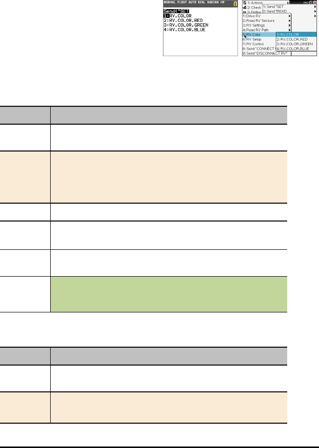
RV Color…
Send("SET Commands
RGB LED on Rover - This supports the same commands and parameters as the RGB
LED on the TI-Innovator™ Hub.
•RV Color…
– Send("SET
–RV.COLOR
–RV.COLOR.RED
–RV.COLOR.GREEN
–RV.COLOR.BLUE
RV.COLOR
Command: RV.COLOR
Command
Syntax:
RV.COLOR
Code
Sample:
Send "SET RV.COLOR
[SET] RV.COLOR rr gg bb [[BLINK] b [[TIME]
s.ss]]
Range: N/A
Describe: Set the RGB color to be displayed on the Rover's RGB LED.
Same syntax as for all RGB LED operations with COLOR, etc.
Result: Return the current RGB color, as a three-element list, that is being
displayed on the Rover's RGB LED
Type or
Addressable
Component:
Control
Note: This Rover control command is sent and executed in a queue.
RV.COLOR.RED
Command: RV.COLOR.RED
Command
Syntax:
RV.COLOR.RED
Code
Sample:
Send "SET RV.COLOR.RED
TI-Innovator™ Hub Commands version 1.2 117

118 TI-Innovator™ Hub Commands version 1.2
Command: RV.COLOR.RED
[SET] RV.COLOR.RED rr [[BLINK] b [[TIME]
s.ss]]
Range: N/A
Describe:
Result: Set the RED color to be displayed on the Rover's RGB LED.
Type or
Addressable
Component:
Control
Note: This Rover control command is sent and executed in a queue.
RV.COLOR.GREEN
Command: RV.COLOR.GREEN
Command
Syntax:
RV.COLOR.GREEN
Code
Sample:
Send "SET RV.COLOR.GREEN
[SET] RV.COLOR.GREEN gg [[BLINK] b [[TIME]
s.ss]]
Range: N/A
Describe:
Result: Set the GREEN color to be displayed on the Rover's RGB LED.
Type or
Addressable
Component:
Control
Note: This Rover control command is sent and executed in a queue.
RV.COLOR.BLUE
Command: RV.COLOR.BLUE
Command
Syntax:
RV.COLOR.BLUE
Code
Sample:
Send "SET RV.COLOR.BLUE

Command: RV.COLOR.BLUE
[SET] RV.COLOR.BLUE bb [[BLINK] b [[TIME]
s.ss]]
Range: N/A
Describe:
Result: Set the BLUE color to be displayed on the Rover's RGB LED.
Type or
Addressable
Component:
Control
Note: This Rover control command is sent and executed in a queue.
TI-Innovator™ Hub Commands version 1.2 119
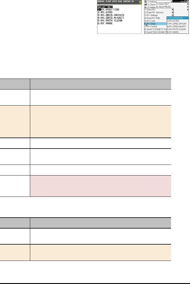
120 TI-Innovator™ Hub Commands version 1.2
RV Setup…
Send("SET Commands
•RV Setup…
– Send("SET
–RV.POSITION
–RV.GYRO
–RV.GRID.ORIGIN
–RV.GRID.M/UNIT
–RV.PATH CLEAR
–RV MARK
RV.POSITION
Command: RV.POSITION
Command
Syntax:
RV.POSITION
Code
Sample:
Send "SET RV.POSITION"
[SET] RV.POSITION xxx yyy
[hhh [[DEGREES]|RADIANS|GRADIANS]]
Range: N/A
Describe: Sets the coordinate position and optionally the heading of the Rover on
the virtual grid.
Result: Rover configuration is updated.
Type or
Addressable
Component:
Setting
RV.GYRO
Command: RV.GYRO
Command
Syntax:
RV.GYRO
Code
Sample:
Send "SET RV.GYRO"
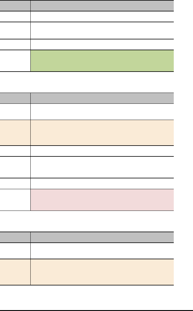
Command: RV.GYRO
Range: N/A
Describe: Sets the on-board Gyroscope.
Result:
Type or
Addressable
Component:
Control (for Gyroscope)
RV.GRID.ORIGIN
Command: RV.GRID.ORIGIN
Command
Syntax:
RV.GRID.ORIGIN
Code
Sample:
Send "SET RV.GRID.ORIGIN"
[SET} RV.GRID.ORIGIN
Range: N/A
Describe: Sets RV as being at current grid origin point of (0,0). The "heading" is set to
0.0 resulting in the current position of the RV now set to pointing down a
virtual x-axis toward positive x values.
Result:
Type or
Addressable
Component:
Setting
RV.GRID.M/UNIT
Command: RV.GRID.M/UNIT
Command
Syntax:
RV.GRID.M/UNIT
Code
Sample:
Send "SET RV.GRID.M/UNIT"
[SET] RV.GRID.M/UNIT nnn
TI-Innovator™ Hub Commands version 1.2 121

122 TI-Innovator™ Hub Commands version 1.2
Command: RV.GRID.M/UNIT
Range: N/A
Describe: Set the size of a "grid unit" on the virtual grid. Default is 10 units per meter
(100 mm / 10 cm per unit grid). A value of 5 means 5 units per meter or
200 mm / 20 cm per unit grid). A value of 20 means 20 units per meter, or
50 mm / 5 cm per unit grid.
Result:
Type or
Addressable
Component:
Setting
RV.PATH CLEAR
Command: RV.PATH CLEAR
Command
Syntax:
RV.PATH CLEAR
Code
Sample:
Send "SET RV.PATH CLEAR"
[SET] RV.PATH CLEAR
Range: N/A
Describe: Clears any pre-existing path / waypoint information. Recommended
before doing a sequence of movement operations where waypoint / path-
list information is desired.
Result:
Type or
Addressable
Component:
Setting
RV MARK
Command: RV MARK
Command
Syntax:
RV MARK
Code
Sample:
Send "SET RV MARK"
[SET] RV MARK [[TIME] s.ss]

Command: RV MARK
Range: N/A
Describe: Enable RV to make a "mark" with a pen at the specified time interval
(default is 1 second if not specified).
A time value of 0.0 turns OFF marking.
Marking ONLY happens if the Rover is moving in a forward direction.
Result:
Type or
Addressable
Component:
Setting (for Rover)
TI-Innovator™ Hub Commands version 1.2 123
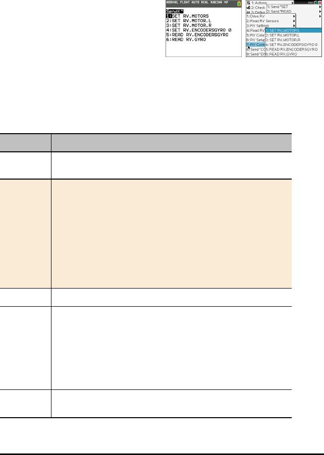
124 TI-Innovator™ Hub Commands version 1.2
RV Control…
SEND(" Commands
Wheel commands and other commands relevant for learning foundations of the Rover
vehicle.
•RV Control …
– Send("
–SET RV.MOTORS
–SET RV.MOTOR.L
–SET RV.MOTOR.R
–SET RV.ENCODERSGYRO 0
–READ RV.ENCODERSGYRO
–READ RV.GYRO
SET RV.MOTORS
Command: SET RV.MOTORS
Command
Syntax:
SET RV.MOTORS
Code
Sample:
Send "SET RV.MOTORS"
[SET] RV.MOTORS [LEFT][CW|CCW]
<pwm value|BRAKE|COAST>
[RIGHT][CW|CCW]
<pwm value|BRAKE|COAST>
[DISTANCE ddd [M|[UNITS]|REV|FT]]
| [TIME s.ss]
Range: N/A
Describe: Set left or right or both motor PWM values. Negative values imply CCW
and Positive values imply CW. Left CW=backward motion. Left
CCW=forward motion. Right CW=forward motion, Right CCW=backward
motion. PWM values may be numeric from -255 to +255, or keywords
"COAST" or "BRAKE". Value of 0 is stop (coast).
Use of the DISTANCE option is only available if the RV is connected with all
sensors. CONNECT RV MOTORS means no sensors are available to
measure distance, so the DISTANCE option is an error in this instance.
Result: Both the LEFT and RIGHT motor, managed as a single object for direct
control (advanced) use.
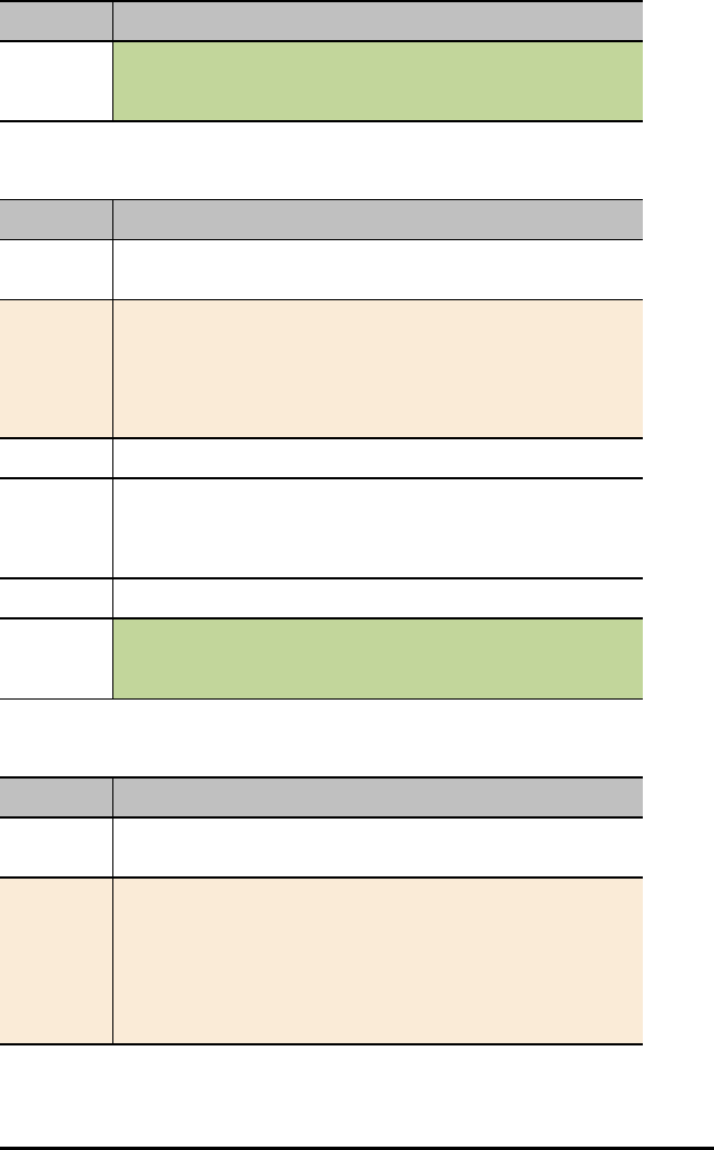
Command: SET RV.MOTORS
Type or
Addressable
Component:
Control
Note: This Rover control command is sent and executed in a queue.
SET RV.MOTOR.L
Command: SET RV.MOTOR.L
Command
Syntax:
SET RV.MOTOR.L
Code
Sample:
Send "SET RV.MOTOR.L"
[SET] RV.MOTOR.L [CW|CCW] <+/-pwm
value|BRAKE|COAST>
[TIME s.ss] | [DISTANCE ddd [[UNITS]
|M|REV|FT]]
Range: N/A
Describe: Set left motor direct PWM value. CCW = forward, CW = backward, pwm
value negative = forward, positive = backward. TIME option available in all
modes, DISTANCE option available only when RV is fully connected (not
the RV MOTORS option).
Result: Left wheel motor and control for direct control (advanced) use.
Type or
Addressable
Component:
Control
Note: This Rover control command is sent and executed in a queue.
SET RV.MOTOR.R
Command: SET RV.MOTOR.R
Command
Syntax:
SET RV.MOTOR.R
Code
Sample:
Send "SET RV.MOTOR.R"
[SET] RV.MOTOR.R [CW|CCW] <+/-pwm
value|BRAKE|COAST>
[TIME s.ss] | [DISTANCE ddd [[UNITS]
|M|REV|FT]]
TI-Innovator™ Hub Commands version 1.2 125

126 TI-Innovator™ Hub Commands version 1.2
Command: SET RV.MOTOR.R
Range: N/A
Describe: Set right motor direct PWM value. CW = forward, CCW = backward, pwm
value positive = forward, negative = backward. TIME option available in all
modes, DISTANCE option available only when RV is fully connected (not
the RV MOTORS option).
Result: Right wheel motor and control for direct control (advanced) use.
Type or
Addressable
Component:
Control
Note: This Rover control command is sent and executed in a queue.
SET RV.ENCODERSGYRO 0
Command: SET RV.ENCODERSGYRO 0
Command
Syntax:
SET RV.ENCODERSGYRO 0
Code
Sample:
Send "SET RV.ENCODERSGYRO 0"
Range: N/A
Describe: Reset the left and right encoder, coupled with the gyro and operating time
information.
Result:
Type or
Addressable
Component:
Control
Note: This Rover control command is sent and executed in a queue.
READ RV.ENCODERSGYRO
Command: READ RV.ENCODERSGYRO
Command
Syntax:
READ RV.ENCODERSGYRO
Code
Sample:
Send "READ RV.ENCODERSGYRO"
Range: N/A
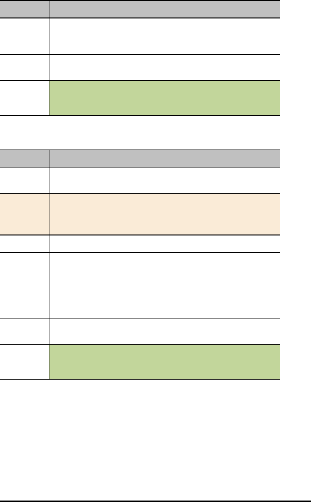
Command: READ RV.ENCODERSGYRO
Describe: The left and right encoder, coupled with the gyro and operating time
information.
Result: List of values of current left and right encoder, coupled with gyro and
operating time information
Type or
Addressable
Component:
Control
Note: This Rover READ command is executed immediately.
READ RV.GYRO
Command: READ RV.GYRO
Command
Syntax:
READ RV.GYRO
Code
Sample:
Send "READ RV.GYRO"
READ RV.GYRO [[DEGREES]|RADIANS|GRADIANS]
Range: N/A
Describe: The gyroscope is used to maintain the heading of Rover while it’s in
motion. It can also be used to measure the change in angle during turns.
The gyroscope is ready to use after the CONNECT RV command is
processed.
The GYRO object shall be usable even when the RV is not in motion.
Result: Returns current gyro sensor angular deviation from 0.0, reading partially
drift-offset compensated.
Type or
Addressable
Component:
Control
Note: This Rover READ command is executed immediately.
TI-Innovator™ Hub Commands version 1.2 127
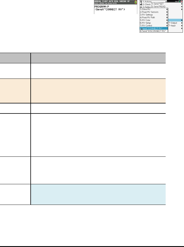
128 TI-Innovator™ Hub Commands version 1.2
Send "CONNECT RV"
SEND("CONNECT RV") Commands
CONNECT RV - initializes the hardware connections.
• Connects RV and inputs and outputs built into the RV.
• Resets the Path and the Grid Origin.
• Sets the units per meter to default value.
•Send("CONNECT RV")
CONNECT RV
Command: CONNECT RV
Command
Syntax:
CONNECT RV [MOTORS]
Code
Sample:
Send "CONNECT RV"
Send "CONNECT RV MOTORS"
Range: N/A
Describe: The "CONNECT RV" command configures the TI-Innovator™ Hub
software to work with the TI-Innovator™ Rover.
It establishes the connections to the various devices on the Rover – two
motors, two encoders, one gyroscope, one RGB LED and one
color sensor. It also clears the various counters and sensor values. The
optional ‘MOTORS’ parameter configures only the motors and allows
direct control of motors without the additional peripherals.
Result: Connects the Rover Vehicle to the TI-Innovator™ Hub.
This establishes connections with the motor driver, color sensor,
gyroscope, ultrasonic ranger, and RGB LED.
The Rover is now ready to be programmed
Type or
Addressable
Component:
All components of the Rover - two motors, two encoders, one
gyroscope, one RGB LED and one color sensor.
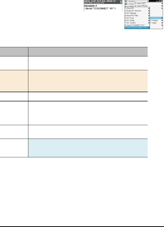
Send "DISCONNECT RV"
SEND("DISCONNECT RV") Commands
DISCONNECT RV - disconnects all the hardware peripherals from the Hub.
Format: Send("DISCONNECT RV")
•Send("DISCONNECT RV")
DISCONNECT RV
Command: DISCONNECT RV
Command
Syntax:
DISCONNECT RV
Code
Sample:
Send "DISCONNECT RV"
DISCONNECT RV
Range: N/A
Describe: The "DISCONNECT RV" command removes the logical connections
between the TI-Innovator™ Hub and the TI-Innovator™ Rover.
It also clears the counters and sensor values. It allows the use of the
breadboard port of the TI-Innovator™ Hub with other devices.
Result: The TI-Innovator™ Hub is now logically disconnected from the TI-
Innovator™ Rover
Type or
Addressable
Component:
N/A
TI-Innovator™ Hub Commands version 1.2 129
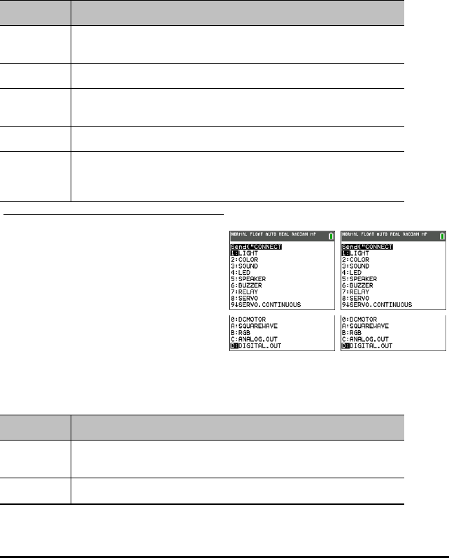
130 TI-Innovator™ Hub Commands version 1.2
CONNECT - Output
CONNECT associates a given control or sensor with a pin or port on the TI-Innovator. If
the specified control or sensor is currently in use, an error will be generated. If the pin
or port specified in the CONNECT command is currently in use, an error will be
generated.
The CONNECT command does not generate an active response, but a variety of errors
may occur during a connection attempt, such as pin-in-use, unsupported, invalid
options, bad options, etc.
CONNECT 'something i' [TO] IN1/IN2/IN3/OUT1/OUT2/OUT3/BB1
Command: CONNECT
Command
Syntax:
CONNECT
Range:
Describe: Associates a sensor or control with a given port or pin(s). Places the
respective pin(s) in use
Result:
Type or
Addressable
Component:
TI-84 Plus CE TI-Nspire™ CX
LIGHT
Command: LIGHT
Command
Syntax:
CONNECT LIGHT
Range:

Command: LIGHT
Describe: This command is not needed for typical use since the on-board LIGHT (i.e.
RED LED) is automatically connected.
Re-connect a previously disconnected on-board RED LED. The LIGHT is
always connected when the system is reset, or powered-on, or the BEGIN
command is used to restore system state. No pin number is required.
CONNECT LIGHT
Result: Connects on-board digital LED (red) to known fixed pin. Digital only.
Type or
Addressable
Component:
Control
COLOR
Command: COLOR
Command
Syntax:
CONNECT COLOR
Range:
Describe: This command is not needed for typical use since the on-board COLOR LED
is automatically connected.
(Re-)connect the internal RGB LED. No pins are required for this command
to operate as the internal pins are known. This sensor is automatically
connected when the TI-Innovator is initially powered, and when the BEGIN
command is used. When disconnected, two PWM signals are freed for
external use by other pins.
CONNECT COLOR
Result: Connects on-board RGB LED to fixed pins on board. Uses 3 PWMs.
Type or
Addressable
Component:
Control
SOUND
Command: SOUND
Command
Syntax:
CONNECT SOUND
TI-Innovator™ Hub Commands version 1.2 131

132 TI-Innovator™ Hub Commands version 1.2
Command: SOUND
Range:
Describe: This command is not needed for typical use since the on-board object
SOUND is automatically connected.
Re-connect the on-board speaker for sound generation. No pin needed as
it uses known, fixed pin for signal.
CONNECT SOUND
Result: Connects on-board speaker to fixed output digital pin.
Type or
Addressable
Component:
Control
LED i [TO] OUT n/BB n
Command: LED i [TO] OUT n/BB n
Command
Syntax:
CONNECT LED i [TO] OUT n/BB n
Range:
Describe: This object provides the ability to connect external LED objects. The LED
object is either connected to a PWM function (if available, and the pin
connecting to supports it), or a digital output pin which will be driven at
50% duty cycle; or the specified blink rate if one is specified in the SET
operation.
CONNECT LED 1i [TO] BB3
CONNECT LED 2i [TO] OUT1
Result: LED connected to specific port.
Type or
Addressable
Component:
Control
SPEAKER i [TO] OUT n/BB n
Command: SPEAKER i [TO] OUT n/BB n
Command
Syntax:
CONNECT SPEAKER i [TO] OUT n/BB n

Command: SPEAKER i [TO] OUT n/BB n
Range:
Describe: Connect an external speaker for sound generation. Requires a digital
output pin.
CONNECT SPEAKER 1 [TO] OUT 1
CONNECT SPEAKER i [TO] BB 3
Result: Connect a speaker to a digital output port or pin.
Type or
Addressable
Component:
Control
BUZZER i [TO] OUT n/BB n
Command: BUZZER i [TO] OUT n/BB n
Command
Syntax:
CONNECT BUZZER i [TO] OUT n/BB n
Range:
Describe: Connect an external active buzzer to an output digital pin. Active buzzers
play a tone when their signal is set high/on, and stop the tone when the
signal is dropped to ground. For piezo or passive buzzers, use the
SPEAKER object type to allow generation of multiple tones.
CONNECT BUZZER i [TO] OUT1
Result: ACTIVE buzzers connect to a digital pin.
Type or
Addressable
Component:
Control
RELAY i [TO] OUT n/BB n
Command: RELAY i [TO] OUT n/BB n
Command
Syntax:
CONNECT RELAY i [TO] OUT n/BB n
Range:
Describe: With external power required, connect a relay module to a given control
TI-Innovator™ Hub Commands version 1.2 133

134 TI-Innovator™ Hub Commands version 1.2
Command: RELAY i [TO] OUT n/BB n
signal pin. Since the control is digital, as long as external power is present,
any pin may be used.
CONNECT RELAY 1 [TO] BB 3
CONNECT RELAY 1 [TO] OUT 2
Result: Relays.
Type or
Addressable
Component:
Control
SERVO i [TO] OUT n
Command: SERVO i [TO] OUT n
Command
Syntax:
CONNECT SERVO i [TO] OUT n
Code
Sample:
Range:
Describe: Used to connect either a normal sweep servo motor, or a continuous
servo motor. External power must be provided before attempting to
connect the servo.
CONNECT SERVO 1 [TO] OUT 1
Result: Servo motor is connected to port.
Type or
Addressable
Component:
Control
SERVO.CONTINUOUS i [TO] BB 6
Command: SERVO.CONTINUOUS i [TO] BB 6
Command
Syntax:
CONNECT SERVO.CONTINUOUS i [TO] BB 6
Code
Sample:

Command: SERVO.CONTINUOUS i [TO] BB 6
Range:
Describe: Used to connect either a normal sweep servo motor, or a continuous
servo motor. External power must be provided before attempting to
connect the servo.
CONNECT SERVO.CONTINUOUS i [TO] BB 6
Result: Servo motor with -90 to 90 degree movement.
Type or
Addressable
Component:
Control
DCMOTOR i [TO] OUT n/BB n
Command: DCMOTOR i [TO] OUT n/BB n
Command
Syntax:
CONNECT DCMOTOR i [TO] OUT n/BB n
Range:
Describe: Connect an external DC Motor object. This object requires the presence of
power on the external power connector to allow operation. These objects
share the number-space with the SQUAREWAVE output objects and
ANALOG.OUT objects. The associated pin is configured as a digital output
signal.
CONNECT DCMOTOR i [TO] OUT1
Result: Connect DCMOTOR to a digital output pin.
Type or
Addressable
Component:
Control
RGB i / COLOR [TO] BB r BB g BB b
Command: RGB i / COLOR [TO] BB r BB g BB b
Command
Syntax:
CONNECT RGB i / COLOR [TO] BB r BB g BB b
Range:
TI-Innovator™ Hub Commands version 1.2 135

136 TI-Innovator™ Hub Commands version 1.2
Command: RGB i / COLOR [TO] BB r BB g BB b
Describe: Connects an external RGB LED to three PWM-capable pins. If insufficient
PWM pins are available for mapping to PWM function, an error will be
given. To connect an external RGB, the on-board RGB LED should be
DISCONNECTed before the attempt to connect the external RGB is
performed.
CONNECT RGB 1 [TO] BB8 BB9 BB10
Result: Digital pins supporting PWM.
Type or
Addressable
Component:
Control
SQUAREWAVE i [TO] OUT n/BB n
Command: SQUAREWAVE i [TO] OUT n/BB n
Command
Syntax:
CONNECT SQUAREWAVE i [TO] OUT n/BB n
Range:
Describe: Connect a software generated digital waveform generator object. These
objects share the number-space with the DCMOTOR and ANALOG.OUT
output objects. The associated pin is configured as a digital output signal.
CONNECT SQUAREWAVE n [TO] BB 2
Result: Digital output squarewave from 1 to 500 hz.
Type or
Addressable
Component:
Control
ANALOG.OUT i [TO] OUT i/BB i
Command: ANALOG.OUT i [TO] OUT n/BB n
Command
Syntax:
CONNECT ANALOG.OUT i [TO] OUT n/BB n
Range:
Describe: Connect a generic “analog” output control to a pin/port that supports
analog input. ANALOG.OUT shares number space with DCMOTOR and
SQUAREWAVE objects.

Command: ANALOG.OUT i [TO] OUT n/BB n
CONNECT ANALOG.OUT i [TO] OUT 1
CONNECT ANALOG.OUT i [TO] BB 4
CONNECT ANALOG.OUT i [TO] BB 1
Result: Connect analog output to pin. If pin supports hardware pulse with
modulation (PWM), the object uses.
If the pin does not support hardware-generated PWM, the sketch will
generate PWM in software at 490 Hz with the duty cycle specfic between 0
(none) and 255 (full on).
Type or
Addressable
Component:
Control
DIGITAL.OUT i [TO] OUT n/BB n [[AS] OUTPUT]
Command: DIGITAL.OUT i [TO] OUT n/BB n [[AS] OUTPUT]
Command
Syntax:
CONNECT DIGITAL.OUT i [TO] OUT n/BB n
Range:
Describe: Connects a generic digital object to a specified pin or port. The connected
pin is configured either as a digital output signal, default LOW, or a digital
input signal, default INPUT with no pullup or pulldown enabled.
The index number can refer to either an input or output. The index is
shared by both items since a DIGITAL signal can be either an input or
output.
CONNECT DIGITAL.OUT 1 [TO] OUT n/BB n
Result: Connect pin to digital object default output state, default OUTPUT, low.
Type or
Addressable
Component:
Control/Sensor
TI-Innovator™ Hub Commands version 1.2 137
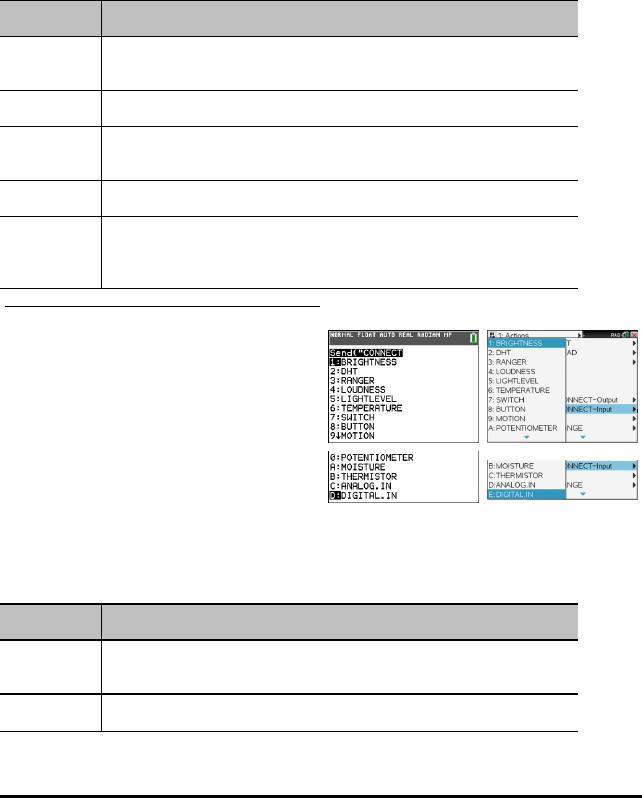
138 TI-Innovator™ Hub Commands version 1.2
CONNECT-Input
CONNECT associates a given control or sensor with a pin or port on the TI-Innovator. If
the specified control or sensor is currently in use, an error will be generated. If the pin
or port specified in the CONNECT command is currently in use, an error will be
generated.
The CONNECT command does not generate an active response, but a variety of errors
may occur during a connection attempt, such as pin-in-use, unsupported, invalid
options, bad options, etc.
CONNECT 'something i' [TO] IN1/IN2/IN3/OUT1/OUT2/OUT3/BB1
Command: CONNECT
Command
Syntax:
CONNECT
Range:
Describe: Associates a sensor or control with a given port or pin(s). Places the
respective pin(s) in use
Result:
Type or
Addressable
Component:
TI-84 PlusCE TI-Nspire™ CX
BRIGHTNESS
Command: BRIGHTNESS
Command
Syntax:
CONNECT BRIGHTNESS
Range:
Command: BRIGHTNESS
Describe: This command is not needed for typical use since the on-board
BRIGHTNESS sensor is automatically connected.
(Re-)connect the internal analog ambient light sensor. No pin or port
name is used with this internal object.
Result: Connects on-board light sensor to known analog input pin.
Type or
Addressable
Component:
Sensor
DHT i [TO] IN n
Command: DHT i [TO] IN n
Command
Syntax:
CONNECT DHT i [TO] IN n
Range: Temperature reading default is in Celsius
Humidity reading from 0 to 100 %
Describe: The DHT digital temperature humidity sensor can be connected via this
object. The DHT can be either a DHT11 or DHT22 and is identified
automatically when connected to the system via a digital signal line.
CONNECT DHT i [TO] IN1
Result: Digital humidity/temperature sensors (DHT11/DHT22, type is auto-
detected).
Type or
Addressable
Component:
Sensor
RANGER i [TO] IN n
Command: RANGER i [TO] IN n
Command
Syntax:
CONNECT RANGER i [TO] IN n
Range:
Describe: Connect an external ultrasonic distance ranging module to an input port.
CONNECT RANGER 1i [TO] IN 1
TI-Innovator™ Hub Commands version 1.2 139
140 TI-Innovator™ Hub Commands version 1.2
Command: RANGER i [TO] IN n
Result: Ultrasonic ranging sensors with either individual trigger/echo pins, or
same pin used for trigger/echo.
Type or
Addressable
Component:
Sensor
LOUDNESS i [TO] IN n
Command: LOUDNESS i [TO] IN n
Command
Syntax:
CONNECT LOUDNESS i [TO] IN n
Range:
Describe: The LOUDNESS object measure sound intensity (loudness).
CONNECT LOUDNESS i1 [TO] IN2
Result: Analog sound level sensors.
Type or
Addressable
Component:
Sensor
LIGHTLEVEL i [TO] IN n/BB n
Command: LIGHTLEVEL i [TO] IN n/BB n
Command
Syntax:
CONNECT LIGHTLEVEL i [TO] IN n/BB n
Range: An integer value between 0 and 16383 (14 bit resolution)
Describe: Connects an external light sensor. External light sensors can be analog
sensors.
CONNECT LIGHTLEVEL 1i [TO] IN1
Result: Analog light level sensors is connected to the specific port.
Type or
Addressable
Component:
Sensor
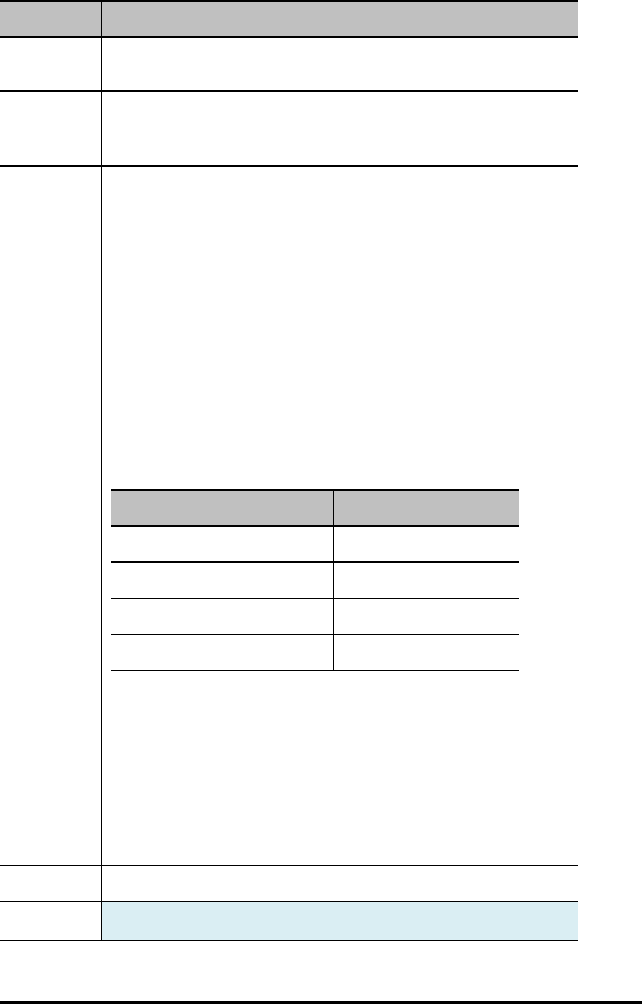
TEMPERATURE i [TO] IN n/BB n
Command: TEMPERATURE i [TO] IN n/BB n
Command
Syntax:
CONNECT TEMPERATURE i [TO] IN n/BB n
Range: Temperature reading default is in Celsius. The range depends on the
specific temperature sensor being used.
Humidity reading from 0 to 100 %
Describe: Connects a temperature sensor to the system using either of several
connection methods.
Note: The default temperature sensor is included in the Breadboard pack
If the sensor is based on a thermistor and provides an analog output, it
uses a single analog input pin. If the sensor is a DS18B20 digital
temperature sensor, it uses a single bi-directional digital GPIO pin.
The analog thermistor temperature sensors is by default, assumed to be a
PTC thermistor. If the thermistor is an NTC style, an optional keyword can
be added to the connect command sequence to change the style of the
thermistor.
The analog thermistor temperature sensor uses a specific set of
thermistor constants, different than those used by the THERMISTOR
object, to convert the reading into a temperature reading. The constants
are used in the Steinhart-Hart model to convert the analog reading to
temperature.
Description Value
C1 8.76741e-8
C2 2.34125e-4
C3 1.129148e-3
R1 – reference resistance 10000.0 ohms
CONNECT TEMPERATURE i [TO] IN 1 – thermistor sensor attached to
analog input.
CONNECT TEMPERATURE i [TO] BB 1 – DS18B20 digital attached to digital
pin.
CONNECT TEMPERATURE i [TO] I2 C – LM75A attached to I2C port.
CONNECT TEMPERATURE i [TO] BB 5 NTC – connect an analog
temperature sensor to analog input and specifies an NTC style thermistor.
CONNECT TEMPERATURE i [TO] BB 6 PTC – connect an analog
temperature sensor to analog input and specifies a PTC style thermistor.
Result: Analog temperature sensor.
Type or Sensor
TI-Innovator™ Hub Commands version 1.2 141
142 TI-Innovator™ Hub Commands version 1.2
Command: TEMPERATURE i [TO] IN n/BB n
Addressable
Component:
SWITCH i [TO] IN n/BB n
Command: SWITCH i [TO] IN n/BB n
Command
Syntax:
CONNECT SWITCH i [TO] IN n/BB n
Range:
Describe: Connect an external switch to a digital input pin. The button task will
monitor the state of the switch allowing reporting for the switch on, not
on, and was on since last checked. The connected pin is set to a digital input
state with its internal pulldown enabled. The other side of the switch is
connected to a power supply (3.3v) pin (or 5v supply if using IN3 port).
Switches share number space with Buttons.
CONNECT SWITCH 1 [TO] IN 1
CONNECT SWITCH 2 [TO] BB 5
Result: Connect a switch object (similar to button, but connected to Vcc instead of
Gnd when enabled.)
Type or
Addressable
Component:
Sensor
BUTTON i [TO] IN n/BB n
Command: BUTTON i [TO] IN n/BB n
Command
Syntax:
CONNECT BUTTON i [TO] IN n/BB n
Range:
Describe: Connect an external button to a digital input pin. The button task will
monitor the state of the button allowing reporting for the button pressed,
not pressed, and was pressed since last checked. The connected pin is set
to a digital input state with its internal pullup enabled. The other side of the
button is connected to a ground pin. Buttons share number space with
Switches.
Command: BUTTON i [TO] IN n/BB n
CONNECT BUTTON i [TO] IN1
Result: Digital button/switch/etc.
Type or
Addressable
Component:
Sensor
MOTION i [TO] IN n/BB n
Command: MOTION i [TO] IN n/BB n
Command
Syntax:
CONNECT MOTION i [TO] IN n/BB n
Range:
Describe: Connects a digital PIR (passive infrared) motion detection sensor to a
digital input pin. This sensor is monitored the same as button objects for a
three-state result.
CONNECT MOTION 1i [TO] IN 1
Result: Passive I/R motion detectors.
Type or
Addressable
Component:
Sensor
POTENTIOMETER i [TO] IN n/BB n
Command: POTENTIOMETER i [TO] IN n/BB n
Command
Syntax:
CONNECT POTENTIOMETER i [TO] IN n/BB n
Range:
Describe: Connect an external slide or rotary potentiometer to an analog input pin.
CONNECT POTENTIOMETER 1i [TO] IN 2
CONNECT POTENTIOMETER 1 [TO] BB 2
Result: Rotary- potentiometer sensors.
Type or Sensor
TI-Innovator™ Hub Commands version 1.2 143
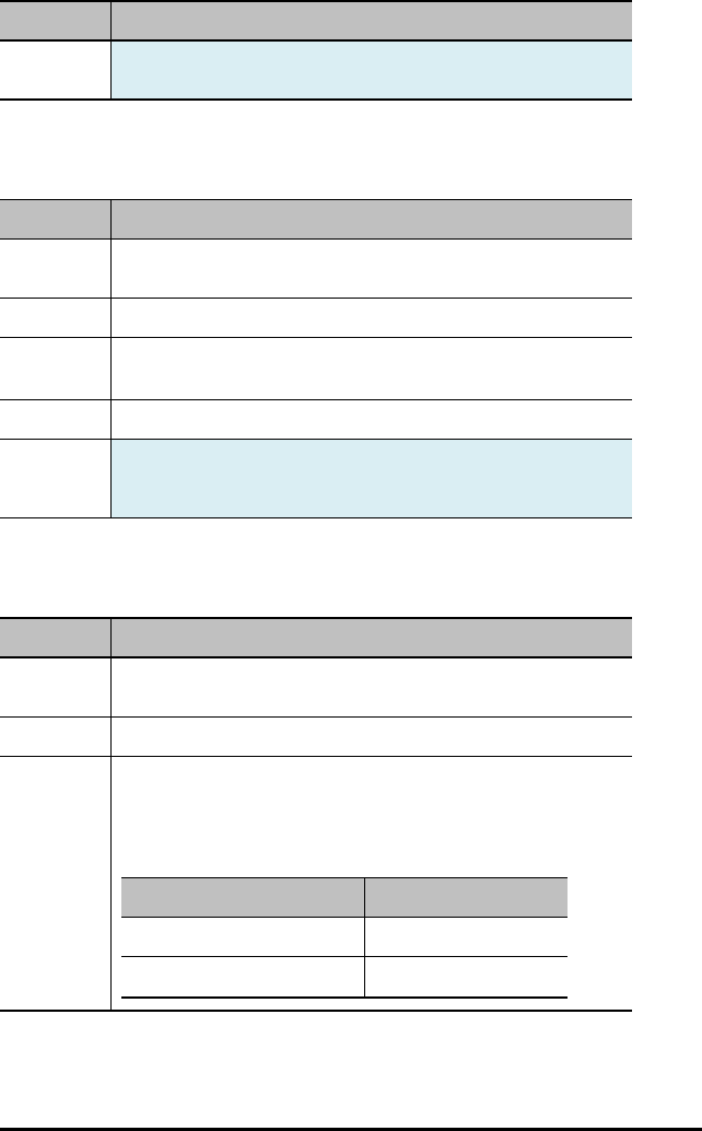
144 TI-Innovator™ Hub Commands version 1.2
Command: POTENTIOMETER i [TO] IN n/BB n
Addressable
Component:
MOISTURE i [TO] IN n/BB n
Command: MOISTURE i [TO] IN n/BB n
Command
Syntax:
CONNECT MOISTURE i [TO] IN n/BB n
Range: An integer value between 0 and 16383 (14 bit resolution)
Describe: Connect an analog moisture sensor to return relative moisture readings.
CONNECT MOISTURE 1i [TO] IN 1
Result: Analog moisture sensors.
Type or
Addressable
Component:
Sensor
THERMISTOR i [TO] IN n/BB n
Command: THERMISTOR i [TO] IN n/BB n
Command
Syntax:
CONNECT THERMISTOR i [TO] IN n/BB n
Range:
Describe: Connects a PTC thermistor to the system using a single analog input pin.
The thermistor sensor uses the following values in the Steinhart-Hart
model to convert the reading into a temperature. These values match
those in the TI Temperature probe that came with the CBL™ System and TI
Lab Cradle.
Description Value
C1 1.33342e-7
C2 2.22468e-4
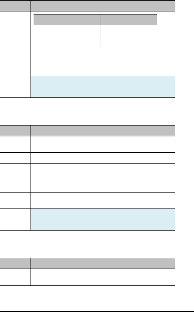
Command: THERMISTOR i [TO] IN n/BB n
Description Value
C3 1.02119e-3
R1 – reference resistance 15000.0 ohms
CONNECT THERMISTOR i [TO] IN 1
CONNECT THERMISTOR i [TO] BB 5
Result: Analog thermistor.
Type or
Addressable
Component:
Sensor
ANALOG.IN i [TO] IN n/BB n
Command: ANALOG.IN i [TO] IN n/BB n
Command
Syntax:
CONNECT ANALOG.IN i [TO] IN n/BB n
Range:
Describe: Connect a generic “analog” input sensor to a pin/port that supports
analog input.
CONNECT ANALOG.IN i [TO] IN 1
CONNECT ANALOG.IN i [TO] BB 5
Result: Connect analog input to pin that supports that function (error if pin is not
analog-input capable).
Type or
Addressable
Component:
Sensor
DIGITAL.IN i [TO] IN n/BB n [[AS] INPUT|PULLUP|PULLDOWN]
Command: DIGITAL.IN i [TO] IN n/BB n [[AS] INPUT|PULLUP|PULLDOWN]
Command
Syntax:
CONNECT DIGITAL.IN i [TO] IN n/OUT n/BB n
TI-Innovator™ Hub Commands version 1.2 145
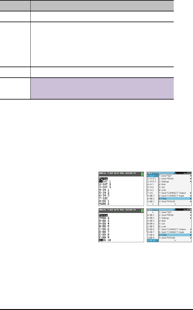
146 TI-Innovator™ Hub Commands version 1.2
Command: DIGITAL.IN i [TO] IN n/BB n [[AS] INPUT|PULLUP|PULLDOWN]
Range:
Describe: Connects a generic digital object to a specified pin or port. The connected
pin is configured either as a digital output signal, default LOW, or a digital
input signal, default INPUT with no pullup or pulldown enabled.
The index number can refer to either an input or output. The index is
shared by both items since a DIGITAL signal can be either an input or
output.
CONNECT DIGITAL.IN 1 [TO] IN 1
Result: Connect pin to digital object default input state, default INPUT.
Type or
Addressable
Component:
Control/Sensor
Ports
Settings menu contains operations to set the state of digital and analog pin operations
such as the LED in the TI-Innovator™ Hub or a connected servo motor movement to
states such as ON, OFF, CW (clockwise), and CCW (counterclockwise).
– 1: OUT 1
– 2: OUT 2
– 3: OUT 3
– 4: IN 1
– 5: IN 2
– 6: IN: 3
– 7: I2C
– 8: BB 1
– 9: BB 2
– 0: BB 3
– A: BB 4
– B: BB 5
– C: BB 6
– D: BB 7
– E: BB 8
– F: BB 9
– G: BB 10
TI-84 Plus CE
See TI-84 Plus CE
Programming
TI-Nspire™ CX
See: TI-Nspire™ CX
Programming
See also: Breadboard Components and Usable Pins

TI-Innovator™ Hub Commands version 1.2 147
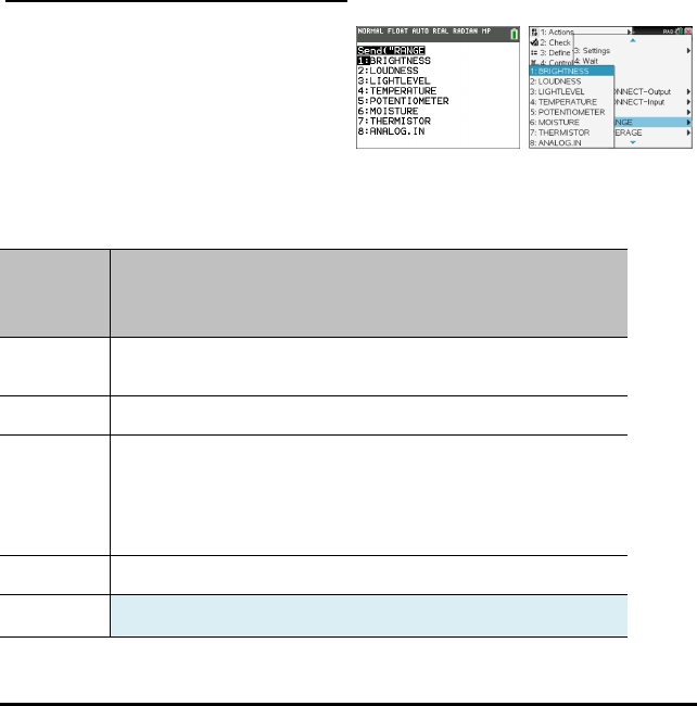
148 TI-Innovator™ Hub Commands version 1.2
RANGE
The RANGE command is used with several analog input sensors to re-map the internal
ADC (Analog to Digital Converter) range of 0 to 16383 (14-bit ADC values) to a floating
point range specified as the parameters to this command, along with the sensor to
which the range is applied. The format for setting the range of a sensor is RANGE
sensor [i] minimum maximum. To remove/reset to default the range from a given
sensor, set the minimum and maximum value to zero. The minimum value must be
less than the maximum value when setting a valid range.
A sensors current range, if present, can be obtained by READ sensor [i] RANGE. A two-
element list of numbers in the form {minimum, maximum } will be returned.
Note: If no range has been applied to the sensor, an error will be returned if an
attempt to read the sensor range is performed .
An individual sensors averaging value may be obtained by READ sensor [i] RANGE.
RANGE 'something' (for analog devices, maps ADC range from 0 to 16383 to the range
specified, min < max, min, max any values.)
TI-84 Plus CE TI-Nspire™ CX
BRIGHTNESS minimum maximum
Command: BRIGHTNESS minimum maximum
Advanced user
Command
Syntax:
RANGE BRIGHTNESS minimum maximum
Range:
Describe: Changes/Sets the mapping of ADC input values from the ADC 0-16383
range to a user-selected range. The resulting sensor reading is mapped to
this and a floating point result is returned. By default, the on-board
BRIGHTNESS sensor is ranged to a 0-100 range.
RANGE BRIGHTNESS minimum maximum
Result: Set mapping for on-board brightness/light sensor.
Type or Sensor
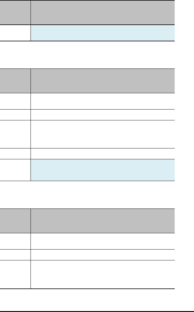
Command: BRIGHTNESS minimum maximum
Advanced user
Addressable
Component:
LOUDNESS i minimum maximum
Command: LOUDNESS i minimum maximum
Advanced user
Command
Syntax:
RANGE LOUDNESS i minimum maximum
Range:
Describe: Changes/Sets the mapping of ADC input values from the ADC 0-16383
range to a user-selected range. The resulting sensor reading is mapped to
this and a floating point result is returned.
RANGE LOUDNESS i minimum maximum
Result: Set mapping for sound-level analog sensor.
Type or
Addressable
Component:
Sensor
LIGHTLEVEL i minimum maximum
Command: LIGHTLEVEL i minimum maximum
Advanced user
Command
Syntax:
RANGE LIGHTLEVEL i minimum maximum
Range: An integer value between 0 and 16383 (14 bit resolution)
Describe: Changes/Sets the mapping of ADC input values from the ADC 0-16383
range to a user-selected range. The resulting sensor reading is mapped to
this and a floating point result is returned.
RANGE LIGHTLEVEL i minimum maximum
TI-Innovator™ Hub Commands version 1.2 149
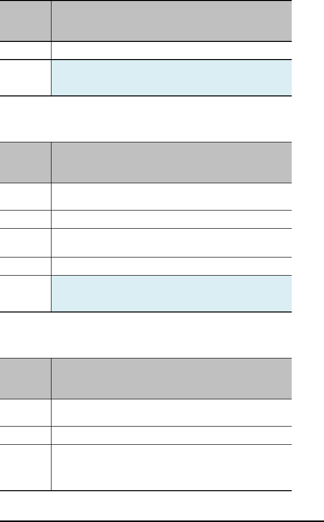
150 TI-Innovator™ Hub Commands version 1.2
Command: LIGHTLEVEL i minimum maximum
Advanced user
Result: Set mapping for off-board light sensor (analog).
Type or
Addressable
Component:
Sensor
TEMPERATURE i minimum maximum
Command: TEMPERATURE i minimum maximum
Advanced user
Command
Syntax:
RANGE TEMPERATURE i minimum maximum
Range:
Describe: .
RANGE TEMPERATURE i minimum maximum
Result: Set mapping for soil moisture analog sensor.
Type or
Addressable
Component:
Sensor
POTENTIOMETER i minimum maximum
Command: POTENTIOMETER i minimum maximum
Advanced user
Command
Syntax:
RANGE POTENTIOMETER i minimum maximum
Range:
Describe: Changes/Sets the mapping of ADC input values from the ADC 0-16383
range to a user-selected range. The resulting sensor reading is mapped to
this and a floating point result is returned. RANGE POTENTIOMETER i
minimum maximum
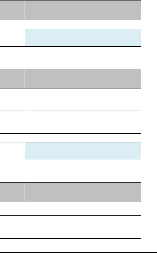
Command: POTENTIOMETER i minimum maximum
Advanced user
Result: Set mapping for rotary/linear potentiometers.
Type or
Addressable
Component:
Sensor
MOISTURE i minimum maximum
Command: MOISTURE i minimum maximum
Advanced user
Command
Syntax:
RANGE MOISTURE i minimum maximum
Range: An integer value between 0 and 16383 (14 bit resolution)
Describe: Changes/Sets the mapping of ADC input values from the ADC 0-16383
range to a user-selected range. The resulting sensor reading is mapped to
this and a floating point result is returned.
RANGE MOISTURE i minimum maximum
Result: Set mapping for soil moisture analog sensor.
Type or
Addressable
Component:
Sensor
THERMISTOR i minimum maximum
Command: THERMISTOR i minimum maximum
Advanced user
Command
Syntax:
RANGE THERMISTOR i minimum maximum
Range:
Describe: .
RANGE THERMISTOR i minimum maximum
TI-Innovator™ Hub Commands version 1.2 151
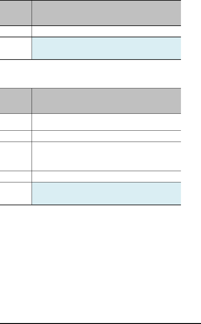
152 TI-Innovator™ Hub Commands version 1.2
Command: THERMISTOR i minimum maximum
Advanced user
Result: Set mapping for xxxxxxxxxx.
Type or
Addressable
Component:
Sensor
ANALOG.IN i minimum maximum
Command: ANALOG.IN i minimum maximum
Advanced user
Command
Syntax:
RANGE ANALOG.IN i minimum maximum
Range:
Describe: Changes/Sets the mapping of ADC input values from the ADC 0-16383
range to a user-selected range. The resulting sensor reading is mapped to
this and a floating point result is returned.
RANGE ANALOG.IN i minimum maximum
Result: Set mapping for generic analog input objects.
Type or
Addressable
Component:
Sensor
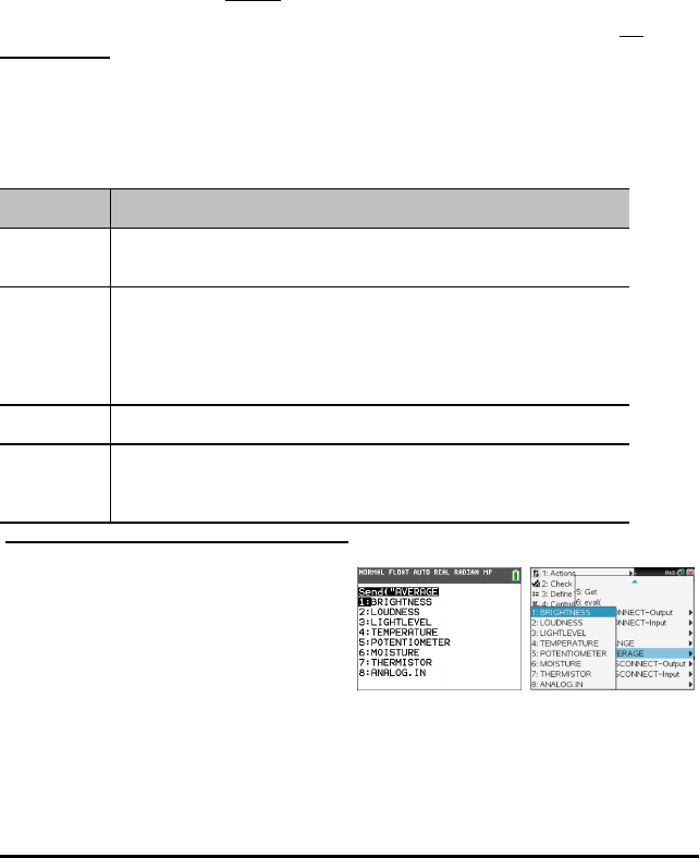
AVERAGE
The AVERAGE command is used to set the number of ADC (Analog to Digital converter)
samples taken to represent a single analog sensor reading. By default, the TI-
Innovator™ Hub sets a global value of three (3) readings to be taken for a sensor
measurement. This is done to reduce variation due to noise etc. This default is
adjustable between 1 and 25 by the SET AVERAGING n command. The current default
can be obtained by the READ AVERAGING command.
For individual sensors, the default can be changed after the CONNECT operation by
using the AVERAGE command. The format is AVERAGE sensor [i] value where sensor is
a sensor from the table below, [i] is the index, if needed to identify the specific sensor,
and value is a number from 1 to 25.
The sensor, when a sample is requested, will take value number of readings, 10
microseconds apart, summing the readings together and averaging them over the
number of readings taken.
An individual sensors averaging value may be obtained by READ sensor [i] AVERAGE.
AVERAGE 'something' (for analog devices, sets the individual oversampling value for
reading, from 1 to 25)
Command: AVERAGE
Command
Syntax:
AVERAGE
Describe: Specifies the number of analog readings to take on a specific sensor to
obtain a single reading of that sensor. Valid values are from 1 to 25
readings, taken 10 microseconds apart and averaged together. Sensors
use the system default of 3 readings if not altered by changing the system
global setting via a SET AVERAGING command.
Result:
Type or
Addressable
Component:
TI-84 Plus CE TI-Nspire™ CX
TI-Innovator™ Hub Commands version 1.2 153
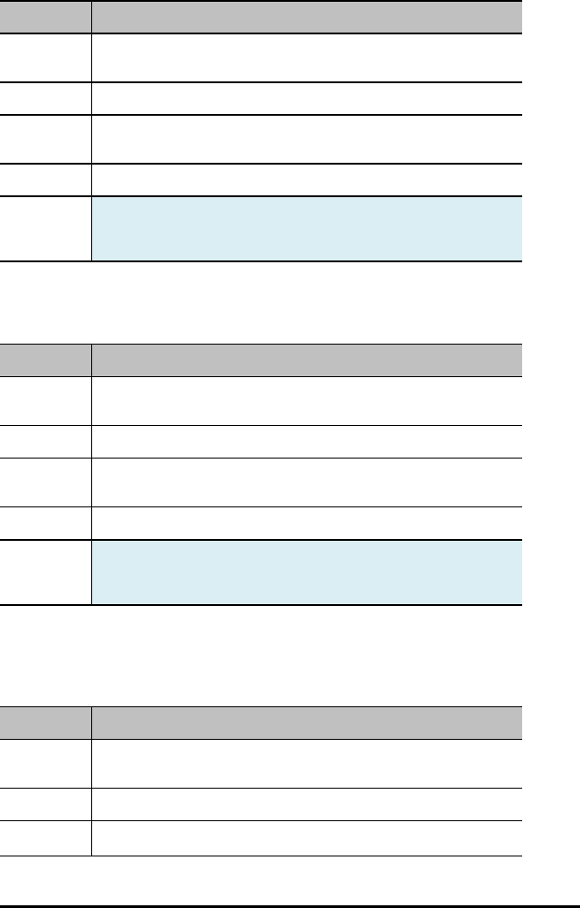
154 TI-Innovator™ Hub Commands version 1.2
BRIGHTNESS n
Command: BRIGHTNESS n
Command
Syntax:
AVERAGE BRIGHTNESS n
Range: Where nranges from 1 to 25
Describe: Set the number of readings from the ADC to be used for the on-board light
sensor.
Result: Set oversampling for on-board brightness/light sensor.
Type or
Addressable
Component:
Sensor
LOUDNESS i n
Command: LOUDNESS i n
Command
Syntax:
AVERAGE LOUDNESS i n
Range: – where nranges from 1 to 25
Describe: Set the number of readings from the ADC to be used with an external
sound loudness sensor.
Result: Set oversampling for sound-level analog sensor.
Type or
Addressable
Component:
Sensor
LIGHTLEVEL i n
Command: LIGHTLEVEL i n
Command
Syntax:
AVERAGE LIGHTLEVEL i n
Range: – where nranges from 1 to 25
Describe: Set the number of readings from the ADC to be used for the external light
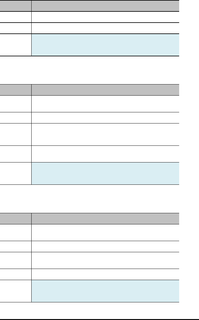
Command: LIGHTLEVEL i n
sensor connected to an analog input. Does not support I2C light sensors.
Result: Set oversampling for off-board light sensor (analog).
Type or
Addressable
Component:
Sensor
TEMPERATURE i n
Command: TEMPERATURE i n
Command
Syntax:
AVERAGE TEMPERATURE i n
Range: Where nranges from 1 to 25
Describe: Set the number of readings from the ADC to be used for the external
temperature sensor connected to an analog input. Does not support I2C
or digital temperature sensors.
Result: When using an analog-style thermistor temperature sensor, oversample
this many times.
Type or
Addressable
Component:
Sensor
POTENTIOMETER i n
Command: POTENTIOMETER i n
Command
Syntax:
AVERAGE POTENTIOMETER i n
Range: Where nranges from 1 to 25
Describe: Set the number of readings from the ADC to be used with an external
potentiometer, either a linear or rotary model.
Result: Set oversampling for rotary/linear potentiometers.
Type or
Addressable
Component:
Sensor
TI-Innovator™ Hub Commands version 1.2 155
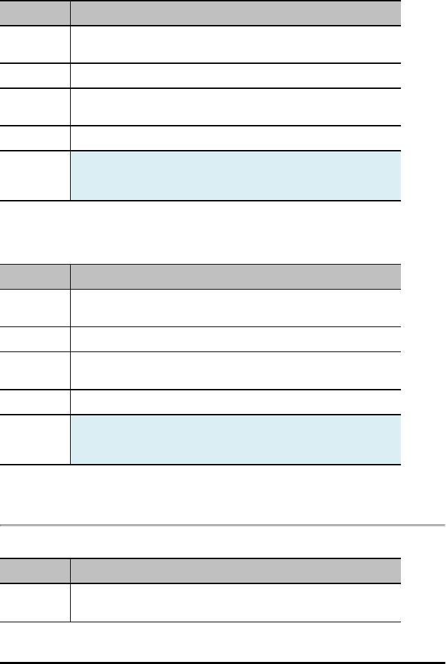
156 TI-Innovator™ Hub Commands version 1.2
MOISTURE i n
Command: MOISTURE i n
Command
Syntax:
AVERAGE MOISTURE i n
Range: – where nranges from 1 to 25
Describe: Set the number of readings from the ADC to be used with an external
moisture sensor.
Result: Set oversampling for soil moisture analog sensor.
Type or
Addressable
Component:
Sensor
THERMISTOR i n
Command: THERMISTOR i n
Command
Syntax:
AVERAGE THERMISTOR i n
Range: Where nranges from 1 to 25
Describe: Set the number of readings from the ADC to be used with an external
thermistor connected to an analog input.
Result: Set oversampling for thermistor device analog input.
Type or
Addressable
Component:
Sensor
ANALOG.IN i n
Command: ANALOG.IN i n
Command
Syntax:
AVERAGE ANALOG.IN i n
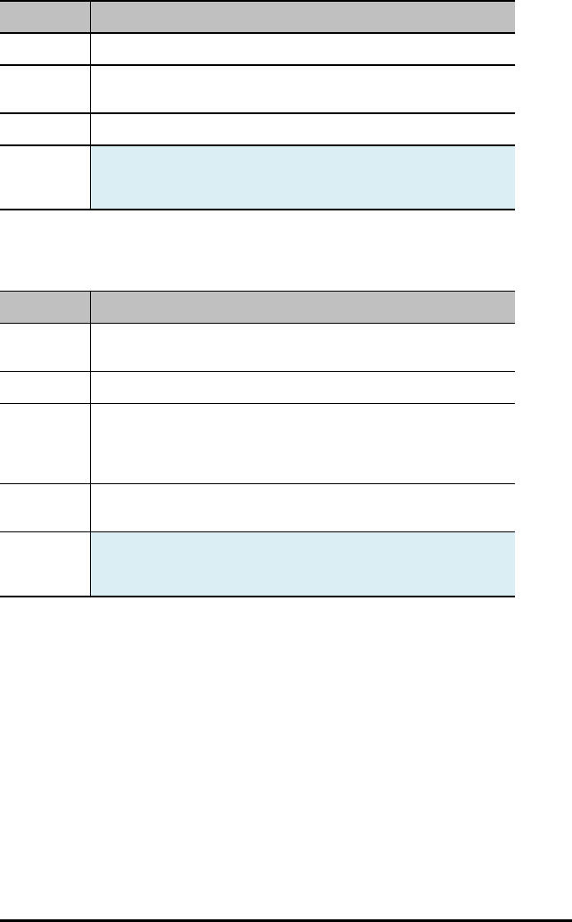
Command: ANALOG.IN i n
Range: Where nranges from 1 to 25
Describe: Set the number of readings from the ADC to be used for the analog sensor
attached to this generic analog item.
Result: Sets oversampling count for generic analog input.
Type or
Addressable
Component:
Sensor
PERIOD n
Command: PERIOD n
Command
Syntax:
PERIOD n
Range:
Describe: The AVERAGE command is somewhat unique for PERIOD in that it specifies
how many distinct periods are to be measured and averaged together to
obtain the desired measurement. Up to 25 samples may be taken to
obtain the period measurement for a given pin.
Result: Set number of samples of frequency to take to be average together to
generate period.
Type or
Addressable
Component:
Sensor
TI-Innovator™ Hub Commands version 1.2 157
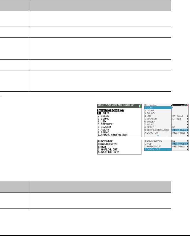
158 TI-Innovator™ Hub Commands version 1.2
DISCONNECT-Output
DISCONNECT breaks the association between a specified control or sensor and the
pin/port it is associated with. If the specified sensor or control is not currently
connected to anything, an error is generated.
The DISCONNECT command does not generate an active response, other than possible
error responses. Pins associated with an actively connected sensor, or control, are
released from use and, in general, are set to a digital input state with no enabled
pullup/pulldown.
DISCONNECT - disconnect something that has been connected, by index if needed.
Command: DISCONNECT-Output
Command
Syntax:
DISCONNECT
Range:
Describe: Removes the association of a sensor or control with a pin, or set of pins, if
such association exists.
Places the pin(s) back to an OUTPUT state.
Result: .
Type or
Addressable
Component:
TI-84 Plus CE TI-Nspire™ CX
LIGHT
Command: LIGHT
Command
Syntax:
DISCONNECT LIGHT

Command: LIGHT
Range:
Describe: Disconnect the on-board RED LED used for direct program control from
the system.
Result: On-board LED disconnected
Type or
Addressable
Component:
Control
COLOR
Command: COLOR
Command
Syntax:
DISCONNECT COLOR
Range:
Describe: Disconnects the on-board RGB LED item from use. This action (in the initial
release of the TI-Innovator™) frees three (3) hardware map-able PWM
signals for use on other pins..
Result: Disconnect on-board RGB LED.
Type or
Addressable
Component:
Control
SOUND
Command: SOUND
Command
Syntax:
DISCONNECT SOUND
Range:
Describe: Disconnect the on-board speaker from its digital pin.
Result: Disconnects on-board speaker.
TI-Innovator™ Hub Commands version 1.2 159

160 TI-Innovator™ Hub Commands version 1.2
Command: SOUND
Type or
Addressable
Component:
Control
SPEAKER i
Command: SPEAKER i
Command
Syntax:
DISCONNECT SPEAKER i
Range:
Describe: Disconnect an external speaker from its digital pin.
Result: Disconnect a speaker from a digital output pin.
Type or
Addressable
Component:
Control
BUZZER i
Command: BUZZER i
Command
Syntax:
DISCONNECT BUZZER i
Range:
Describe: Disconnect an active buzzer from the system.
Active buzzers play a tone when their signal is set high/on, and stop the
tone when the signal is dropped to ground.
DISCONNECT BUZZER i
Result: ACTIVE buzzers disconnected from a digital pin.
Type or
Addressable
Component:
Control
RELAY i
Command: RELAY i
Command
Syntax:
DISCONNECT RELAY i
Range:
Describe: Disconnect a digital relay interface from the system.
Result: Relay disconnected.
Type or
Addressable
Component:
Control
SERVO i
Command: SERVO i
Command
Syntax:
DISCONNECT SERVO i
Code
Sample:
Range:
Describe: Disconnect a sweep or continuous SERVO motor from the digital pin
associated with the motor.
Result: Servo motor disconnected.
Type or
Addressable
Component:
Control
SERVO CONTINOUS i
Command: SERVO CONTINOUSi
Command DISCONNECT SERVO CONTINOUSi
TI-Innovator™ Hub Commands version 1.2 161

162 TI-Innovator™ Hub Commands version 1.2
Command: SERVO CONTINOUSi
Syntax:
Code
Sample:
Range:
Describe: Disconnect a sweep or continuous SERVO motor from the digital pin
associated with the motor.
Result: Servo motor disconnected.
Type or
Addressable
Component:
Control
DCMOTOR i
Command: DCMOTOR i
Command
Syntax:
DISCONNECT DCMOTOR i
Range:
Describe: Disconnects a DCMOTOR object from the system. DCMOTOR,
ANALOG.OUT, and SQUAREWAVE all share the same number space of
items. DCMOTOR requires external power.
Result: Disconnect DCMOTOR from pin.
Type or
Addressable
Component:
Control
SQUAREWAVE i
Command: SQUAREWAVE i
Command
Syntax:
DISCONNECT SQUAREWAVE i

Command: SQUAREWAVE i
Range:
Describe: Disconnect the software generated squarewave generator from an
associated digital output pin. The pin reverts to digital input upon
disconnect.
Result: Disconnect squarewave function from pin(s), stops squarewave
generation.
Type or
Addressable
Component:
Control
RGB i
Command: RGB i
Command
Syntax:
DISCONNECT RGB i
Range:
Describe: Disconnect an external RGB LED from the system. These objects use three
hardware PWM signals to properly operate, so in the initial product
release, the on-board COLOR object must be disconnected to connect one
of these objects.
Result: Disconnect RGB and free up PWM outputs for use elsewhere.
Type or
Addressable
Component:
Control
ANALOG.OUT i
Command: ANALOG.OUT i
Command
Syntax:
DISCONNECT ANALOG.OUT i
Range:
Describe: Disconnects the connected generic analog output device specified, freeing
TI-Innovator™ Hub Commands version 1.2 163

164 TI-Innovator™ Hub Commands version 1.2
Command: ANALOG.OUT i
a hardware map-able PWM if it is in use with the object.
Result: Disconnect generic analog PWM output from pin.
Type or
Addressable
Component:
Control
DIGITAL.OUT i
Command: DIGITAL.OUT i
Command
Syntax:
DISCONNECT DIGITAL.OUT i
Range:
Describe: Disconnect a generic DIGITAL object. The associated pin is reverted to a
digital INPUT pin with no enabled pullup or pulldown. The DIGITAL object
number can be used to refer the same pin in either input, or output form...
Result: Disconnect digital input object.
Type or
Addressable
Component:
Control/Sensor
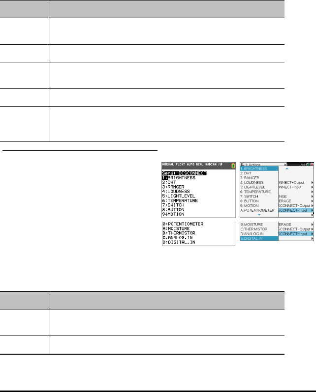
DISCONNECT-Input
DISCONNECT breaks the association between a specified control or sensor and the
pin/port it is associated with. If the specified sensor or control is not currently
connected to anything, an error is generated.
The DISCONNECT command does not generate an active response, other than possible
error responses. Pins associated with an actively connected sensor, or control, are
released from use and, in general, are set to a digital input state with no enabled
pullup/pulldown.
DISCONNECT - disconnect something that has been connected, by index if needed.
Command: DISCONNECT-Input...
Command
Syntax:
DISCONNECT
Range:
Describe: Removes the association of a sensor or control with a pin, or set of pins, if
such association exists. Places the pin(s) back to an INPUT state.
Result: .
Type or
Addressable
Component:
TI-84 Plus CE TI-Nspire™ CX
BRIGHTNESS
Command: BRIGHTNESS
Command
Syntax:
DISCONNECT BRIGHTNESS
Range:
TI-Innovator™ Hub Commands version 1.2 165
166 TI-Innovator™ Hub Commands version 1.2
Command: BRIGHTNESS
Describe: Disconnects the internal connection to the on-board BRIGHTNESS (light
sensor) object.
Result: Disconnect on-board LIGHT sensor.
Type or
Addressable
Component:
Sensor
DHT i
Command: DHT i
Command
Syntax:
DISCONNECT DHT i
Range: Temperature reading default is in Celsius
Humidity reading from 0 to 100 %
Describe: Disconnects the specified digital humidity DHT and temperature sensor
from the system. This also removes that object from the period scan list of
style sensors in the DHT task.
Result: Digital humidity/temperature sensor(s) disconnected.
Type or
Addressable
Component:
Sensor
RANGER i
Command: RANGER i
Command
Syntax:
DISCONNECT RANGER i
Range:
Describe: Disconnect a digital ultrasonic ranging sensor from the two digital pins it
uses.
Result: Ultrasonic ranging sensor disconnected.
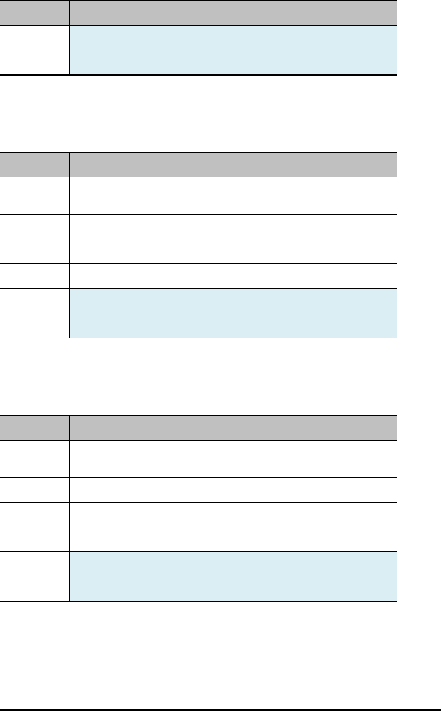
Command: RANGER i
Type or
Addressable
Component:
Sensor
LOUDNESS i
Command: LOUDNESS i
Command
Syntax:
DISCONNECT LOUDNESS i
Range:
Describe: Disconnect an analog sound intensity (LOUDNESS) sensor.
Result: Analog sound level sensor disconnected
Type or
Addressable
Component:
Sensor
LIGHTLEVEL i
Command: LIGHTLEVEL i
Command
Syntax:
DISCONNECT LIGHTLEVEL i
Range:
Describe: Disconnect an external light sensor.
Result: Light sensor disconnected.
Type or
Addressable
Component:
Sensor
TI-Innovator™ Hub Commands version 1.2 167
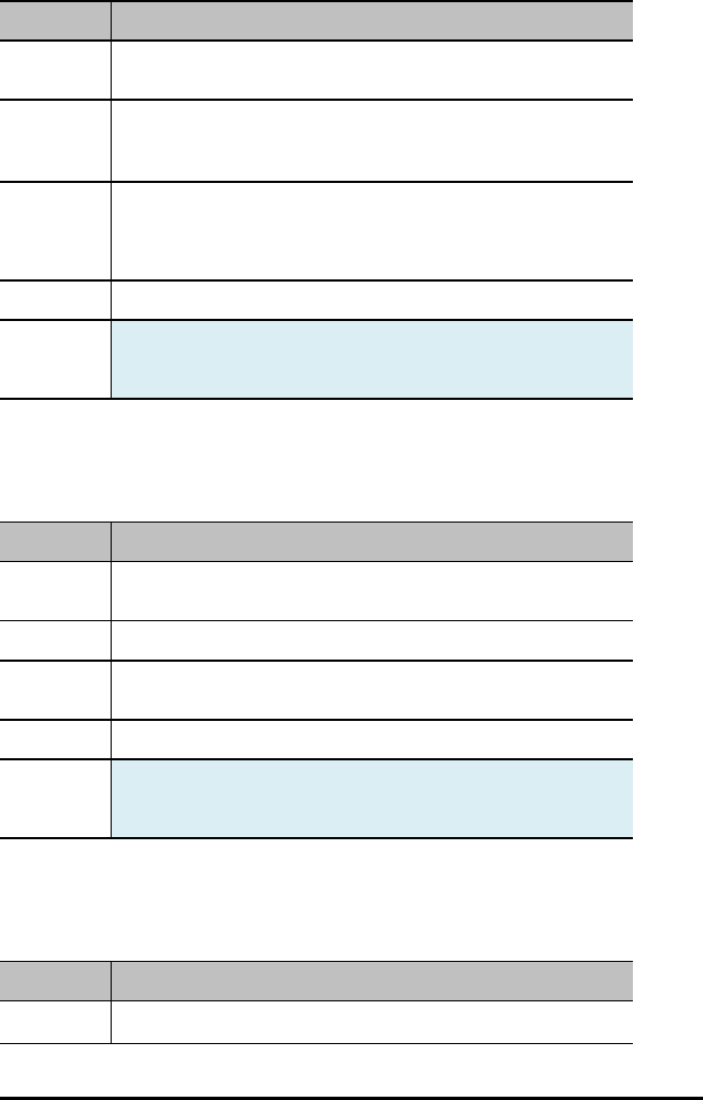
168 TI-Innovator™ Hub Commands version 1.2
TEMPERATURE i
Command: TEMPERATURE i
Command
Syntax:
DISCONNECT TEMPERATURE i
Range: Temperature reading default is in Celsius. The range depends on the
specific temperature sensor being used.
Humidity reading from 0 to 100 %
Describe: Disconnect a connected temperature sensor from the system.
TEMPERATURE sensors can be either analog (thermistor-style).
Disconnecting from the analog or digital reverts the associated pins to
INPUT.
Result: Disconnect temperature sensor.
Type or
Addressable
Component:
Sensor
SWITCH
Command: SWITCH
Command
Syntax:
DISCONNECT SWITCH i
Range:
Describe: Disconnect a switch from its digital pin. The pin reverts to INPUT state, and
the switch is removed from the scanning sequence in the BUTTON task.
Result: disconnect switch object from pin
Type or
Addressable
Component:
Sensor
BUTTON i
Command: BUTTON i
Command DISCONNECT BUTTON i
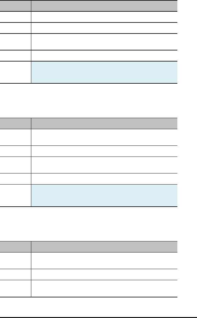
Command: BUTTON i
Syntax:
Range:
Describe: Disconnects the specified button object from the system and removes it
from the list of scanned buttons/switches in the BUTTON task.
Result: Digital button/switch is disconnected.
Type or
Addressable
Component:
Sensor
MOTION i
Command: MOTION i
Command
Syntax:
DISCONNECT MOTION i
Range:
Describe: Disconnects a digital PIR (passive infrared) MOTION detector and
removes the object from the scanning list in the BUTTON task.
Result: Disconnect passive I/R motion detectors
Type or
Addressable
Component:
Sensor
POTENTIOMETER i
Command: POTENTIOMETER i
Command
Syntax:
DISCONNECT POTENTIOMETER i
Range:
Describe: Disconnect an analog variable resistor (POTENTIOMETER) from the
system
TI-Innovator™ Hub Commands version 1.2 169
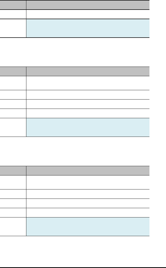
170 TI-Innovator™ Hub Commands version 1.2
Command: POTENTIOMETER i
Result: Disconnect a rotary/linear potentiometer sensors
Type or
Addressable
Component:
Sensor
MOISTURE i
Command: MOISTURE i
Command
Syntax:
DISCONNECT MOISTURE i
Range:
Describe: Disconnect an analog moisture sensor.
Result: Disconnect analog moisture sensors
Type or
Addressable
Component:
Sensor
THERMISTOR i
Command: THERMISTOR i
Command
Syntax:
DISCONNECT THERMISTOR i
Range:
Describe: Disconnect an analog thermistor sensor from the associated pin.
Result: disconnect analog thermistor
Type or
Addressable
Component:
Sensor

ANALOG.IN i
Command: ANALOG.IN i
Command
Syntax:
DISCONNECT ANALOG.IN i
Range:
Describe: Disconnects the connected generic analog input device specified.
Result: Disconnect generic analog input from pin.
Type or
Addressable
Component:
Sensor
DIGITAL.IN i
Command: DIGITAL.IN i
Command
Syntax:
DISCONNECT DIGITAL.IN i
Range:
Describe: Disconnect a generic DIGITAL object. The associated pin is reverted to a
digital INPUT pin with no enabled pullup or pulldown. The DIGITAL object
number can be used to refer the same pin in either input, or output form.
Result: Disconnect digital input object.
Type or
Addressable
Component:
Control/Sensor
TI-Innovator™ Hub Commands version 1.2 171
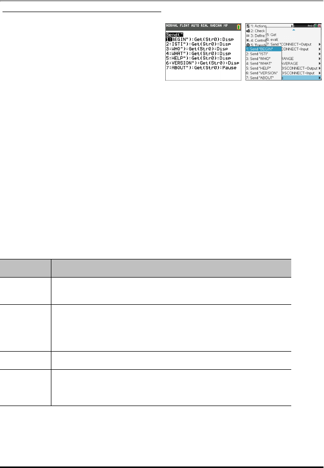
172 TI-Innovator™ Hub Commands version 1.2
MANAGE
The Manage menu pastes a Send( command with the following management items.
Str0 is displayed on Home Screen with information if requested in the command.
TI-84 Plus CE TI-Nspire™ CX
BEGIN
The BEGIN command disconnects all connected sensors and controls, re-initializes all
sensor/control memory within the sketch, and resets the sensor average default value,
error formatting, and flow control defaults.Additionally, all INnport pins, and the
breadboard connector (BBn) pins are set to the INPUT pin mode.All OUTnport pins are
set to the INPUT state, and allowed to float, including OUT3 which will read as high
due to a pullup resistor from the 5V supply on this pin.
When the entire process completes, a response of READY is sent to the host system.
This response must be waited for by the host before any further operations are
performed. Additional commands may be in the command queue to be executed, but
will not be acted upon until this command completes.
BEGIN
Command: BEGIN
Command
Syntax:
SEND("BEGIN"
Describe: Disassociates sensors from ports or pins, and resets all settings back to
defaults.
Disconnects any connected sensor objects and restores system to state as
if RESET button pressed.
Result: Responds with a "READY" when completed.
Type or
Addressable
Component:
Not Applicable
Note: The [: ] is used to sequence command lines on one command line. The Manage…
menu pastes a convenient set of commands to then display the information in Str0 on
the home screen.

ISTI
The ISTI command is used to synchronize communications with the sketch. The
response to this command must be TISTEM. Responses may have a leading NUL (0)
character on initial power-on of the Innovator hub. All responses from the Innovator
hub will be followed with a CR/LF pair that may or may not be stripped by software
layers in the host system prior to the response being received by the application layer
on the host system.
ISTI
Command: ISTI
Command
Syntax:
ISTI
Describe: Send "ISTI", and get response "TISTEM".
Result: Handshake command used to determine presence of a supported “sketch”
on the TI-Innovaotr™ Hub.
Type or
Addressable
Component:
WHO
WHO is an identification command (similar to the ISTI handshake command below)
that can be used to determine what product is present and running the sketch.
The correct response to WHO is "TI INNOVATOR ON MSP432" when this command is
sent to the TI-Innovator Hub.
WHO
Command: WHO
Command
Syntax:
WHO
Describe: Identification command to determine what product is running the sketch.
Send ("WHO")
Get Str0
Disp Str0
Result: Identify the product - TI INNOVATOR ON MSP432.
Type or
Addressable
Component:
TI-Innovator™ Hub Commands version 1.2 173

174 TI-Innovator™ Hub Commands version 1.2
WHAT
The WHAT command is an identification command. The response to WHAT for TI-
Innovator is "TI INNOVATOR HUB".
WHAT
Command: WHAT
Command
Syntax:
WHAT
Describe: Product name query.
Identify the product - "TI INNOVATOR HUB"
Send ("WHAT")
Get Str0
Disp Str0
Result: Identify the product.
Type or
Addressable
Component:
HELP
HELP is used to obtain quick information about each of these commands. The HELP
command-name is sent, and generates a string response with a one-line description of
the given command.
HELP
Command: HELP
Command
Syntax:
HELP
Describe: Provides per command quick help information. i.e. HELP SET, etc.
Result:
Type or
Addressable
Component:

VERSION
The VERSION command has a response that represents the current version of the
sketch running on the TI-Innovator™ Hub.
The version will be of the major.minor.patch.build form in released products; for
example, 1.0.0.
VERSION
Command: VERSION
Command
Syntax:
VERSION
Describe: Returns version number (and possibly Accurev stream name from which
sketch was built).
Result: Report the version of the sketch in format major.minor.patch.build.
Send ("VERSION")
Get Str0
Disp Str0
Type or
Addressable
Component:
ABOUT
The ABOUT command response is the product line name along with a copyright date
and owner. The current response to this command is "TI INNOVATOR (C)2015-2016
TEXAS INSTRUMENTS".
ABOUT
Command: ABOUT
Command
Syntax:
ABOUT
Describe: Product name and copyright information returned.
Send ("ABOUT")
Get Str0
Disp Str0
Result: Returns copyright string.
"TI INNOVATOR (C)2015-2016 TEXAS INSTRUMENTS"
Type or
Addressable
Component:
TI-Innovator™ Hub Commands version 1.2 175

176 TI-Innovator™ Hub Commands version 1.2
Additional Supported Commands
The following sets of supported commands are not found in the Hub Menus.
Additional SET Commands
FORMAT ERROR STRING/NUMBER
Command: FORMAT ERROR STRING/NUMBER
Advanced user
Command
Syntax:
SET FORMAT ERROR STRING/NUMBER
Range:
Describe: Used for setting error return format and optional audible tone on error.
SET FORMAT ERROR STRING/NUMBER – returned error codes in string
or numeric format.
Result: Sets the format for the return of error information (numbers, or strings).
Type or
Addressable
Component:
Setting
FORMAT ERROR NOTE/QUIET
Command: FORMAT ERROR NOTE/QUIET
Advanced user
Command
Syntax:
SET FORMAT ERROR NOTE/QUIET
Range:
Describe: Used for setting error return format and optional audible tone on error.
SET FORMAT ERROR NOTE/QUIET – error display flash accompanied by
speaker sound or no sound.
Result: Enables tones, or disables tones in addition to the string/number reporting

Command: FORMAT ERROR NOTE/QUIET
Advanced user
above.
Type or
Addressable
Component:
Setting
FLOW [TO] ON/OFF
Command: FLOW [TO] ON/OFF
Advanced user
Command
Syntax:
SET FLOW [TO] ON/OFF
Range:
Describe: Enables (ON) or disables (OFF) the software flow control mechanism
between the sketch and the communications hardware.
NOTE: When the SEGDISP module is CONNECTed, this setting determines
whether or not the display module shows error information (flow control
disabled), or command queue depth (flow control enabled).
Result: Turn on xon/xoff flow control, or turn off (no flow control)
Type or
Addressable
Component:
Setting
OUT1/2/3 [TO]
Command: OUT1/2/3 [TO]
Command
Syntax:
OUT1/2/3 [TO] ...
SET OUTn 0-255
SET OUTn HIGH/ON
SET OUTn LOW/OFF
TI-Innovator™ Hub Commands version 1.2 177

178 TI-Innovator™ Hub Commands version 1.2
Command: OUT1/2/3 [TO]
Range: Set analog PWM value on OUT port(s) of the TI-Innovator™Hub
Describe: Direct output of information to a given output port. These are PWM
outputs on the TI-Innovator™ Hub.
Set analog PWM value on TI-Innovator™ Hub OUT port(s).
SET OUTn 0-255 – 0=off, 255=on, anything else is a PWM signal @ 500 Hz
with duty cycle high from 1 to 254, where that range provides a
percentage of the high-time signal of the waveform.
SET OUTn HIGH/ON – same as 255
SET OUTn LOW/OFF – same as 0
Result: Set analog PWM value on OUT port(s) of the TI-Innovator™ Hub
Type or
Addressable
Component:
Port

Additional READ Commands
BUZZER i
Command: BUZZER i
Command
Syntax:
READ BUZZER i
Range:
Describe: Returns the current state of the active buzzer specified; 0 = silent, 1 =
playing tone.
Result: Returns state of active buzzer, 0=silent, 1=on
Type or
Addressable
Component:
Control
COLOR
Command: COLOR
Command
Syntax:
READ COLOR
Range:
Describe: Read the current output state of the on-board COLOR RGB LED with sub-
components .RED,.GREEN,.BLUE. When reading the entire item, a list of
three values is returned, with values between 0 and 255 where 0=off,
255=full on, and values in between indicate PWM levels.
READ COLOR – returns list of 3 values representing {red, green, blue }
PWM levels
READ COLOR.RED
READ COLOR.GREEN
READ COLOR.BLUE
See Also: RGB i
Result: Returns list of 3 values representing {red, green, blue } PWM levels.
TI-Innovator™ Hub Commands version 1.2 179

180 TI-Innovator™ Hub Commands version 1.2
Command: COLOR
Returns RED/GREEN/BLUE values for on-board RGB (color) LED.
Type or
Addressable
Component:
Control
COLOR.RED
Command: COLOR RED
Command
Syntax:
READ COLOR.RED
Range:
Describe: Read the current output state of the on-board COLOR RGB LED with sub-
components .RED,.GREEN,.BLUE. When reading the entire item, a list of
three values is returned, with values between 0 and 255 where 0=off,
255=full on, and values in between indicate PWM levels.
READ COLOR.RED
Result: Returns values representing {red} PWM levels.
Returns RED values for on-board RGB (color) LED.
Type or
Addressable
Component:
Control
COLOR.GREEN
Command: COLOR GREEN
Command
Syntax:
READ COLOR.GREEN
Range:

Command: COLOR GREEN
Describe: Read the current output state of the on-board COLOR RGB LED with sub-
components .RED,.GREEN,.BLUE. When reading the entire item, a list of
three values is returned, with values between 0 and 255 where 0=off,
255=full on, and values in between indicate PWM levels.
READ COLOR.GREEN
Result: Returns list of 3 values representing {red, green, blue } PWM levels.
Returns RED/GREEN/BLUE values for on-board RGB (color) LED.
Type or
Addressable
Component:
Control
COLOR.BLUE
Command: COLOR BLUE
Command
Syntax:
READ COLOR.BLUE
Range:
Describe: Read the current output state of the on-board COLOR RGB LED with sub-
components .RED,.GREEN,.BLUE. When reading the entire item, a list of
three values is returned, with values between 0 and 255 where 0=off,
255=full on, and values in between indicate PWM levels.
READ COLOR.BLUE
Result: Returns list of 3 values representing {red, green, blue } PWM levels.
Returns RED/GREEN/BLUE values for on-board RGB (color) LED.
Type or
Addressable
Component:
Control
TI-Innovator™ Hub Commands version 1.2 181

182 TI-Innovator™ Hub Commands version 1.2
DCMOTOR i
Command: DCMOTOR i
Command
Syntax:
READ DCMOTOR i
Range:
Describe: Motor that converts direct current electrical power into mechanical
power.
Result: Returns whether dcmotor is running (1) or stopped (0).
Type or
Addressable
Component:
Control
DIGITAL.OUT i
Command: DIGITAL.OUT i
Command
Syntax:
READ DIGITAL.OUT i
Range:
Describe: Returns the current state of the digital pin connected to the DIGITAL
object, or the cached state of the digital output value last SET to the object.
Result: Return 0 (output low), 1 (output high).
Type or
Addressable
Component:
Control/Sensor

FORMAT
Command: FORMAT
Advanced user
Command
Syntax:
READ FORMAT
Range:
Describe: Return the current formatting flags for error reporting. The value
returned is a byte value indicating various flags. Masking with values
indicates what error reporting options are active.
1 = ERROR strings reported
2 = ERROR numbers reported
+4 = ERROR TONE enabled, if not set, errors are reported silently.
Result: Read error format (1=strings, 2=numbers, +4 to either: tones enabled).
Type or
Addressable
Component:
Setting
FLOW
Command: FLOW
Advanced user
Command
Syntax:
READ FLOW
Range:
Describe: Returns the current flow control setting; 0=disabled, 1=enabled.
Result: Read current flow control, 0 = none, 1 = xon/xoff
Type or
Addressable
Component:
Setting
TI-Innovator™ Hub Commands version 1.2 183

184 TI-Innovator™ Hub Commands version 1.2
IN1/IN2/IN3
Command: IN1/IN2/IN3
Command
Syntax:
READ IN1
READ IN2
READ IN3
Range:
Describe: Read the value present on the indicated port, and return that value to the
host.
Result: Read value of analog port on TI STEM board
Type or
Addressable
Component:
Port
LAST ERROR
Command: LAST ERROR
Command
Syntax:
READ LAST ERROR
Range:
Describe: Returns the last reported error from the last operation. Depending on the
FORMAT ERROR setting, the response may be a STRING or a NUMBER.
Result: Return last encountered error, resets automatically to 0, no error.
Type or
Addressable
Component:
Setting

LED i
Command: LED i
Command
Syntax:
READ LED i
Range:
Describe: Read the current state of the specified LED. If the LED is digital, a 0 or 1 is
returned indicating the LED is off or on. If the LED is connected to a PWM
output, a value from 0 to 255 will be returned, indicating the current PWM
level where 0 is off, 255 is full on, and values in between indicate the
current PWM setting.
Result: Get state of LED, 0 or 1 if digital, 0-255 if PWM on analog.
Type or
Addressable
Component:
Control
LIGHT
Command: LIGHT
Command
Syntax:
READ LIGHT
Range:
Describe: Returns the state of the on-board RED LED (digital only). A value of 0 is off,
and 1 is on.
Result: Get current state of on-board red LED (0=off, 1=on).
Type or
Addressable
Component:
Control
TI-Innovator™ Hub Commands version 1.2 185

186 TI-Innovator™ Hub Commands version 1.2
OUT1/2/3
Command: OUT1/2/3
Command
Syntax:
READ OUT1
READ OUT2
READ OUT3
Range:
Describe: Read value of current port as input (may be a digital read since these do
not support analog-input.
READ OUT1/OUT2/OUT3
Result: Read value of analog port on TI STEM board.
Type or
Addressable
Component:
Port
PWR
Command: PWR
Command
Syntax:
READ PWR
Range:
Describe: Returns the current state of presence of external power connected to the
PWR port. The PWR port is read, and a status value of 0 (not present) or 1
(present) is returned, based on whether or not external power is
available.
READ PWR
Result: Returns state of external power presence on PWR port (0=not present,
1=ext pwr present).
Type or
Addressable
Component:
Status

RELAY i
Command: RELAY i
Command
Syntax:
READ RELAY i
Range:
Describe: Return the current state of the specified relay. 0 = OFF, 1 = ON.
Result: Read state of relay - 0=not active 1=active.
Type or
Addressable
Component:
Control
RESOLUTION
Command: RESOLUTION
Command
Syntax:
READ RESOLUTION
Range:
Describe: Returns the bit resolution used by the system for ADC readings.
Result: Returns ADC resolution in use, in bits (default is 14).
Type or
Addressable
Component:
Setting
RGB i
Command: RGB i
Command
Syntax:
READ RGB i
TI-Innovator™ Hub Commands version 1.2 187

188 TI-Innovator™ Hub Commands version 1.2
Command: RGB i
Range:
Describe: Same as the COLOR object referenced above, and has sub-objects named
RED,GREEN, and BLUE. This command returns the current PWM level that
the specified object is using.
READ RGB i – returns a 3 element list, consisting of the {red, green, blue }
color level.
READ RED i – returns just the current red-component level.
READ GREEN i
READ BLUE i
Result: Get state of RGB LED, {r,g,b} list values
Type or
Addressable
Component:
Control
RED i
Command: RED i
Command
Syntax:
READ RED i
Range:
Describe: Same as the COLOR object referenced above, and has sub-objects named
RED,GREEN, and BLUE. This command returns the current PWM level that
the specified object is using.
READ RGB i – returns a 3 element list, consisting of the {red, green, blue }
color level.
READ RED i – returns just the current red-component level.
Result: Get state of RGB RED component.
Type or
Addressable
Component:
Control

GREEN i
Command: GREEN i
Command
Syntax:
READ GREEN i
Range:
Describe: Same as the COLOR object referenced above, and has sub-objects named
RED,GREEN, and BLUE. This command returns the current PWM level that
the specified object is using.
READ RGB i – returns a 3 element list, consisting of the {red, green, blue }
color level.
READ GREEN i – returns just the current green-component level.
Result: Get state of RGB GREEN component.
Type or
Addressable
Component:
Control
BLUE i
Command: BLUE i
Command
Syntax:
READ BLUE i
Range:
Describe: Same as the COLOR object referenced above, and has sub-objects named
RED,GREEN, and BLUE. This command returns the current PWM level that
the specified object is using.
READ RGB i – returns a 3 element list, consisting of the {red, green, blue }
color level.
READ BLUE i – returns just the current blue-component level
Result: Get state of RGB BLUE component.
Type or
Addressable
Component:
Control
TI-Innovator™ Hub Commands version 1.2 189

190 TI-Innovator™ Hub Commands version 1.2
SERVO i
Command: SERVO i
Command
Syntax:
READ SERVO i
Range:
Describe: Returns the current position of a sweep servo in the range -90 to 90, OR
the current speed of rotation of a continuous servo motor.
Additionally, the current “calibration” setting for the servo which consists
of a 2-element list representing the lower and upper microsecond pulse
widths corresponding to the sweep/rotation ranges may be read.
READ SERVO i – get current sweep position or rotation speed/direction.
READ SERVO i CALIBRATION – get current microsecond range for sweep
or rotation.
Result: Return current servo position in degrees from -90 to +90.
Type or
Addressable
Component:
Control
SERVO i CALIBRATION
Command: SERVO i CALIBRATION
Advanced user
Command
Syntax:
READ SERVO i CALIBRATION
Range:
Describe: Returns the current position of a sweep servo in the range -90 to 90, OR
the current speed of rotation of a continuous servo motor.
Additionally, the current “calibration” setting for the servo which consists
of a 2-element list representing the lower and upper microsecond pulse
widths corresponding to the sweep/rotation ranges may be read.
READ SERVO i CALIBRATION – get current microsecond range for sweep
or rotation.
Result: Return current servo position in degrees from -90 to +90.
Type or
Addressable
Component:
Control

SOUND
Command: SOUND
Command
Syntax:
READ SOUND
Range:
Describe: Returns a value indicating whether sound is currently being played (1) or
not (0) through the on-board speaker.
Result: Return whether on-board speaker is playing a tone (1) or is silent(0).
Type or
Addressable
Component:
Control
SPEAKER i
Command: SPEAKER i
Command
Syntax:
READ SPEAKER i
Range:
Describe: Returns a value indicating whether sound is currently being played (1) or
not (0) through an external speaker.
Result: Return whether speaker is playing a tone (1) or silent (0).
Type or
Addressable
Component:
Control
TI-Innovator™ Hub Commands version 1.2 191

192 TI-Innovator™ Hub Commands version 1.2
SQUAREWAVE i
Command: SQUAREWAVE i
Command
Syntax:
READ SQUAREWAVE i
Range:
Describe: Returns a 0 the current squarewave object is not active. A value of 1 is
returned if the object is actively generating an output.
Result: Returns whether squarewave is active (1) or not active (0).
Type or
Addressable
Component:
Control
Additional AVERAGE Commands
PERIOD n
Command: PERIOD n
Command
Syntax:
PERIOD n
Range:
Describe: The AVERAGE command is somewhat unique for PERIOD in that it specifies
how many distinct periods are to be measured and averaged together to
obtain the desired measurement. Up to 25 samples may be taken to
obtain the period measurement for a given pin.
Result: Set number of samples of frequency to take to be average together to
generate period.
Type or
Addressable
Component:
Sensor
TI-Innovator™ Hub Commands version 1.2 193
194 TI-Innovator™ Hub Commands version 1.2
Additional CALIBRATION Commands
CALIBRATE
CALIBRATE is used to set various sensor and control values that do not otherwise fit
within a means of setting any other way. For thermistors and temperature sensors
that use an analog input port, it can be used to adjust the coefficients of the Steinhart-
Hart equation used to map thermistor readings to temperature values. For servo
motors, it is used to adjust the PWM pulse width within the range for a servo motor,
where the zero position is set at 1500 microseconds. It is also used to set the
calibration frequency for the DDS signal generator module (default is 24MHz).
For sensors supporting calibration, the value(s) may be obtained by READ sensor [i]
CALIBRATION.
SERVO i / SERVO.CONTINUOUS i
Command: SERVO i /SERVO.CONTINUOUS i minimum maximum
Advanced user
Command
Syntax:
CALIBRATE SERVO i minimum maximum
Code
Sample:
Range:
Describe: Servos operate by using pulse modulation where the high pulse width
determines both direction of servo operation and possibly the speed of
operation. The time between pulses is generally 20 milliseconds and is not
adjustable by this command. The pulse width generally varies around a
mid-point of 1.5 milliseconds (1500 microseconds). Pulse widths less than
1.5 milliseconds cause servo operation in one direction, while pulse widths
greater than 1.5 milliseconds cause operation in the opposite direction.
The CALIBRATE command for SERVO allows programmable changes to
the minimum and maximum pulse widths. Parameters are pulse width
times in microseconds.
Current defaults are minimum 600 and maximum 2400 microseconds.
Result: Set minimum and maximum pulse width for servo motor, values in
microseconds, default 600 and 2400.

Command: SERVO i /SERVO.CONTINUOUS i minimum maximum
Advanced user
Type or
Addressable
Component:
Control
TEMPERATURE i C1 C2 C3 R1
Command: TEMPERATURE i C1 C2 C3 R1
Advanced user
Command
Syntax:
CALIBRATE TEMPERATURE i C1 C2 C3 R1
Range:
Describe: The CALIBRATE command for analog temperature sensors allows
changing the default Steinhart-Hart equation coefficients to match those of
the thermistor element in the sensor being used.
The default values are:
C1: 8.76741e-8
C2: 2.34125e-4
C3: 1.129148e-3
R1: 10000.0 (reference resistor value = 10kΩ)
Result: When using an analog-style thermistor temperature sensor.
Type or
Addressable
Component:
Sensor
THERMISTOR i C1 C2 C3 R1
Command: THERMISTOR i C1 C2 C3 R1
Advanced user
Command
Syntax:
CALIBRATE THERMISTOR i C1 C2 C3 R1
Range:
TI-Innovator™ Hub Commands version 1.2 195

196 TI-Innovator™ Hub Commands version 1.2
Command: THERMISTOR i C1 C2 C3 R1
Advanced user
Describe: The CALIBRATE command for analog thermistors allows changing the
default Steinhart-Hart equation coefficients to match those of the
thermistor element in the sensor being used.
The default values are:
C1: 1.33342e-7
C2: 2.22468e-4
C3: 1.02119e-3
R1: 15000.0 (reference resistor value = 15kΩ)
Result: Where c1/c2/c3 are float constants for the Steinhart-Hart equation.
... that models the thermistor, and r is resistance for the reference.
... resistor used to create a voltage divider with the thermistor.
Type or
Addressable
Component:
Sensor

TI-Innovator™ Hub Data Sheets
The TI-Innovator™ Hub Data Sheets include the following; a product name and number,
a brief description, a product image, specifications, on-board components function, and
Hub commands with simple code samples.
Topic Links
•TI-Innovator™ Hub Data Sheet
-TI-Innovator™ Hub Ports and Breadboard Usable Pins
•TI-Innovator™ Hub On-Board Component Data Sheets
-On-Board RGB LED Data Sheet
-On-Board Red LED Data Sheet
-On-Board Speaker Data Sheet
-On-Board Light Brightness Sensor Data Sheet
-On-Board - Auxiliary Power Indicator Data Sheet
-On-Board Green LED - Power Indicator Data Sheet
-On-Board Red LED - Error Indicator Data Sheet
•USB Mini A to Mini B Cable Data Sheet
•USB Standard A to Mini B Cable Data Sheet
•USB Standard A to Micro B Cable Data Sheet
•TI Wall Charger Data Sheet
•External Battery Data Sheet
TI-Innovator™ Hub Data Sheets 197
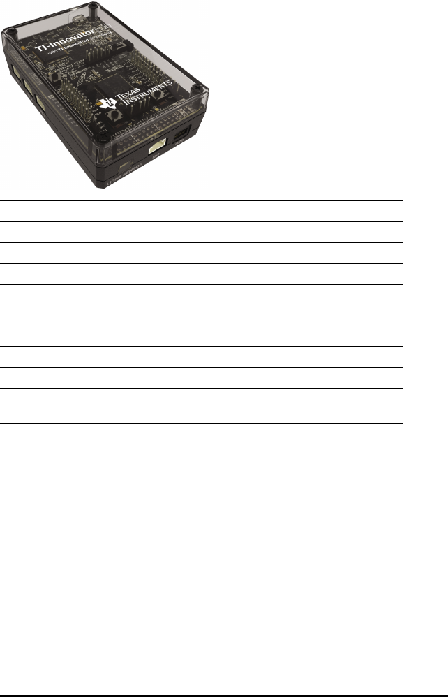
198 TI-Innovator™ Hub Data Sheets
TI-Innovator™ Hub Data Sheet
Title TI-Innovator™ Hub
TI Item Name STEM/BK/B
Quantity 1
Included in TI-Innovator™ Hub
Description Use the TI-Innovator™ Hub with your compatible TI
graphing calculator or TI-Nspire™ software to control
components, read sensors, and create powerful learning
experiences.
Category Hub
Hub Connection Not Applicable
Assembly
Instructions
Not Applicable
Precautions Do not expose the Hub to temperatures above 140˚F
(60˚C).
Do not disassemble or mistreat the Hub.
Do not chain together multiple Hubs through the I/O ports
or the Breadboard Connector.
Use only the USB cables provided with the Hub.
Use only the TI provided power supplies:
• TI Wall Charger included with the TI-Innovator™ Hub
• Optional External Battery 4-AA battery holder included
in the TI-Innovator™ Breadboard Pack
Ensure that the components receiving power from the Hub
do not exceed the Hub’s 1-amp power limit.
Avoid using the Hub to control AC electricity.
See also: TI-Innovator™ Hub Ports and Breadboard Usable
Pins

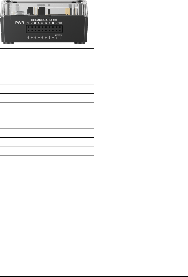
200 TI-Innovator™ Hub Data Sheets
TI-Innovator™ Hub Ports and Breadboard Usable Pins
Breadboard Connector Characteristics
Different pins on the breadboard connector have different capabilities.
Pin Digital I/O Pulse Width
Modulation
(PWM)
ANALOG IN
BB1 Y
BB2 Y
BB3 Y
BB4 Y Y
BB5 Y Y
BB6 Y Y
BB7 Y Y
BB8 Y Y
BB9 Y Y
BB10 Y Y
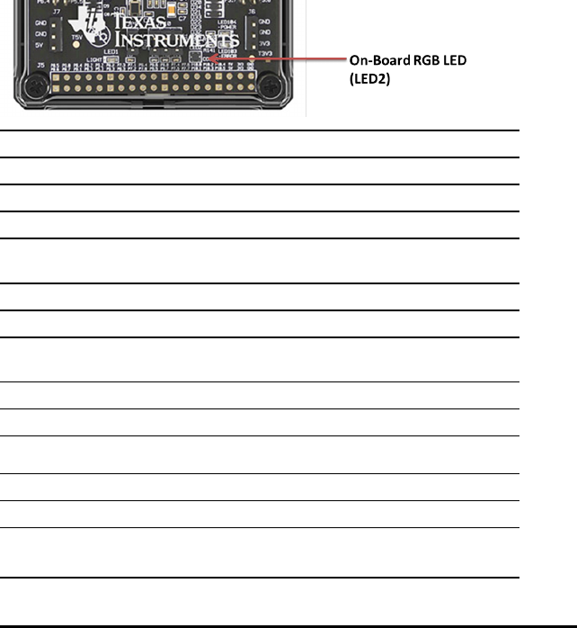
TI-Innovator™ Hub On-Board Component Data Sheets
Topic Links
-On-Board RGB LED Data Sheet
-On-Board Red LED Data Sheet
-On-Board Speaker Data Sheet
-On-Board Light Brightness Sensor Data Sheet
-On-Board - Auxiliary Power Indicator Data Sheet
-On-Board Green LED - Power Indicator Data Sheet
-On-Board Red LED - Error Indicator Data Sheet
On-Board RGB LED Data Sheet
Title On-Board RGB LED
TI Item Name Built into the Hub
Quantity 1
Included in TI-Innovator™ Hub
Description Built-in light-emitting diode (LED) that is capable of
emitting a variety of colors when current passes through it.
Category LEDs and Displays
Hub Connection on-board Hub
Assembly
Instructions
Not Applicable
Precautions Not Applicable
Specifications Not Applicable
HUB Commands
Sketch Object COLOR
Command Syntax Send("SET COLOR …")
ON/OFF/0-255 (red element)
TI-Innovator™ Hub Data Sheets 201
202 TI-Innovator™ Hub Data Sheets
HUB Commands
ON/OFF/0-255 (green element)
ON/OFF/0-255 (blue element)
[BLINK frequency] (in Hz)
[TIME duration] (in seconds)
Code
Sample: Desired Action Code Sample
Turn ON Red and
Green elements of
tri-color LED
Send("SET COLOR ON ON
OFF")
Set Red to full
intensity, Green to
half intensity, Blue
to off
Send("SET COLOR 255
128 0")
Set Red to full
intensity, Green to
half intensity, Blue
to off for 10 seconds
Send("SET COLOR 255
128 0 TIME 10")
Set Red to full
intensity, Green to
half intensity, Blue
to off and blink
them at 2 Hz (2
times a second) for
10 seconds
Send("SET COLOR 255
128 0 BLINK 2 TIME
10")
Turn OFF the Red
element
Send("SET COLOR.RED
0")
Turn ON the Green
element at half
intensity and blink it
at 2 Hz for 10
seconds
Send("SET COLOR.GREEN
128 BLINK 2 TIME 10")
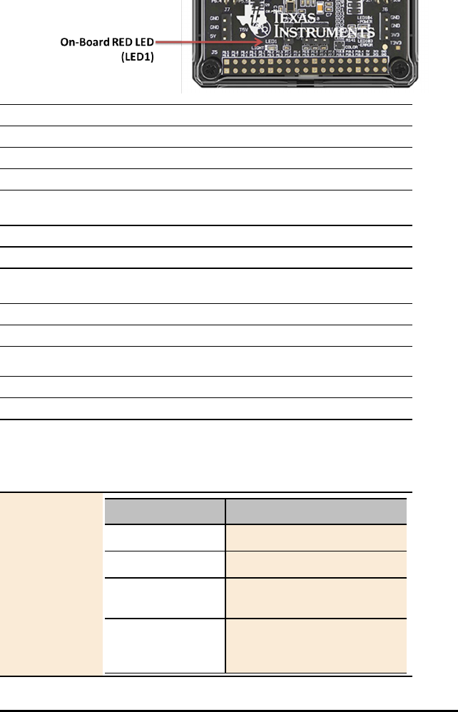
On-Board Red LED Data Sheet
Title On-Board Red LED
TI Item Name Built into the Hub
Quantity 1
Included in TI-Innovator™ Hub
Description Built-in light-emitting diode (LED) that emits a red light
when current passes through it.
Category LEDs and Displays
Hub Connection on-board Hub
Assembly
Instructions
Not Applicable
Precautions Not Applicable
Specifications Not Applicable
HUB Commands
Sketch Object LIGHT
Command Syntax Send("SET LIGHT …")
ON/OFF
[BLINK frequency]
[TIME duration] (in seconds)
Code
Sample: Desired Action Code Sample
Turn LED ON Send("SET LIGHT ON")
Turn LED OFF Send("SET LIGHT OFF")
Turn LED ON for 10
seconds
Send("SET LIGHT ON
TIME 10"
Turn LED ON, blink
it at 2 Hz for 10
seconds
Send("SET LIGHT ON
BLINK 2 TIME 10")
TI-Innovator™ Hub Data Sheets 203


On-Board Speaker Data Sheet
Speaker (at back of Hub) is addressable as "SOUND" in Hub command strings.
Title On-Board Speaker
TI Item Name Built into the Hub
Quantity 1
Included in TI-Innovator™ Hub
Description Built-in speaker located at the back of the Hub. It converts
electrical current into sound you can hear.
Category Sound Output
Hub Connection on-board Hub
Assembly
Instructions
Not Applicable
Precautions Not Applicable
Specifications Not Applicable
HUB Commands
Sketch Object SOUND
Command Syntax Send("SET SOUND …")
Frequency in Hz or Note as C1, CS1, D2, ...
[TIME duration in seconds]
Code
Sample: Desired Action Code Sample
Play tone at 261.23
Hz
Send("SET SOUND
261.23")
Evaluate the
expression 2^8 (=
256) and play that
tone
Send("SET SOUND eval
(2^8)")
TI-Innovator™ Hub Data Sheets 205

206 TI-Innovator™ Hub Data Sheets
HUB Commands
Desired Action Code Sample
Evaluate the
expression 2^8 (=
256) and play that
tone for .25 seconds
Send("SET SOUND eval
(2^8) TIME .25")
Evaluate the
expression 2^9 (=
512) and play that
tone for 0.25
seconds (result of
evaluating 1/4)
Send("SET SOUND eval
(2^9) TIME eval(1/4)")
Turn speaker off Send("SET SOUND OFF")
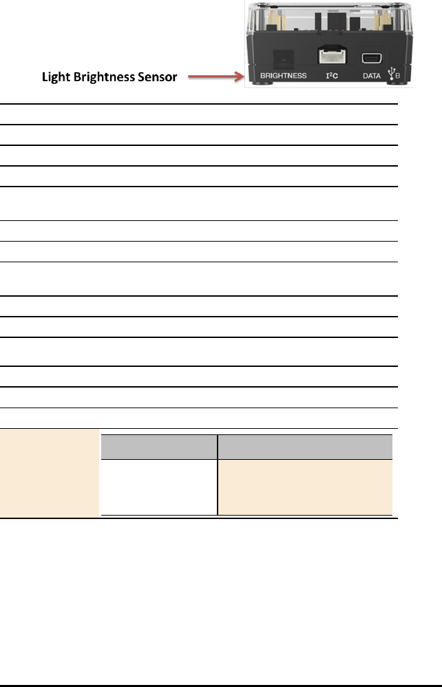
On-Board Light Brightness Sensor Data Sheet
Title On-Board Light Brightness Sensor
TI Item Name Built into the Hub
Quantity 1
Included in TI-Innovator™ Hub
Description Built-in light brightness sensor located at the bottom of the
Hub. The sensor detects light intensity.
Category Environmental Sensors
Hub Connection on-board Hub
Assembly
Instructions
Not Applicable
Precautions Not Applicable
Specifications Not Applicable
HUB Commands
Sketch Object BRIGHTNESS
Command Syntax Send("READ BRIGHTNESS")
Code
Sample: Desired Action Code Sample
Read the built-in
light brightness
sensor
Send("READ
BRIGHTNESS")
Get(B)
TI-Innovator™ Hub Data Sheets 207
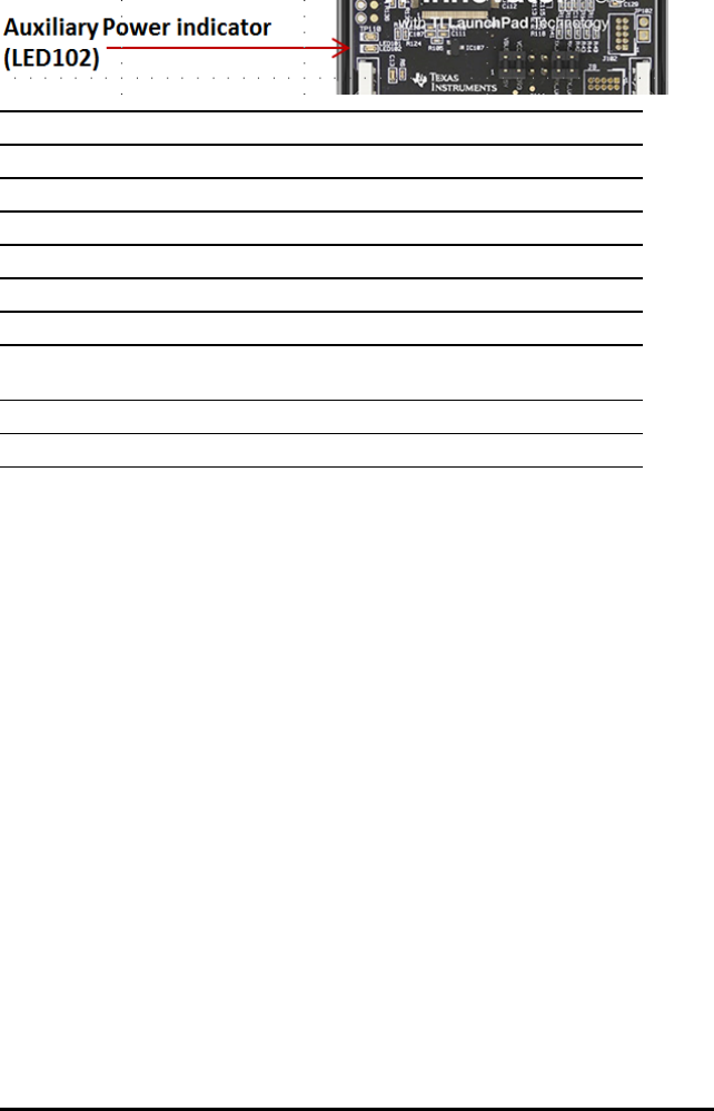
208 TI-Innovator™ Hub Data Sheets
On-Board - Auxiliary Power Indicator Data Sheet
Title Auxiliary Power Indicator (LED102)
TI Item Name Built into the Hub
Quantity 1
Included in TI-Innovator™ Hub
Description Indicates a Auxiliary power connection.
Category LEDs and Displays
Hub Connection on-board
Assembly
Instructions
Not Applicable
Precautions Not Applicable
Specifications Not Applicable

On-Board Green LED - Power Indicator Data Sheet
Title Green LED - Power Indicator
TI Item Name Built into the Hub
Quantity 1
Included in TI-Innovator™ Hub
Description Indicates a USB connection on the DATA port.
Category LEDs and Displays
Hub Connection on-board
Assembly
Instructions
Not Applicable
Precautions Not Applicable
Specifications Not Applicable
TI-Innovator™ Hub Data Sheets 209
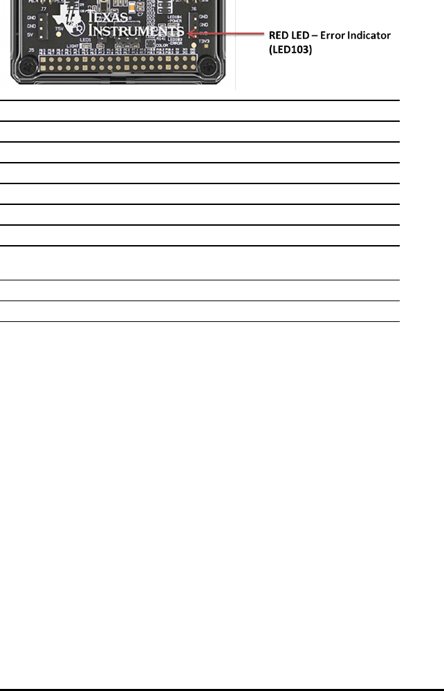
210 TI-Innovator™ Hub Data Sheets
On-Board Red LED - Error Indicator Data Sheet
Title Red LED - Error Indicator
TI Item Name Built into the Hub
Quantity 1
Included in TI-Innovator™ Hub
Description Indicates an error in the sketch command.
Category LEDs and Displays
Hub Connection on-board Hub
Assembly
Instructions
Not Applicable
Precautions Not Applicable
Specifications Not Applicable
See Also: On-Board Red LED

USB Mini A to Mini B Cable Data Sheet
Title USB Mini A to Mini B Cable
TI Item Name XX/CA/USB15/A
Quantity 1
Included in TI-Innovator™ Hub
Description Connects the Hub to a TI-84 Plus CE Graphing Calculator or
a TI-Nspire™ CX Handheld..
Category Accessories
Hub Connection Not Applicable
Assembly
Instructions
Not Applicable
Precautions Not Applicable
Specifications Not Applicable
TI-Innovator™ Hub Data Sheets 211
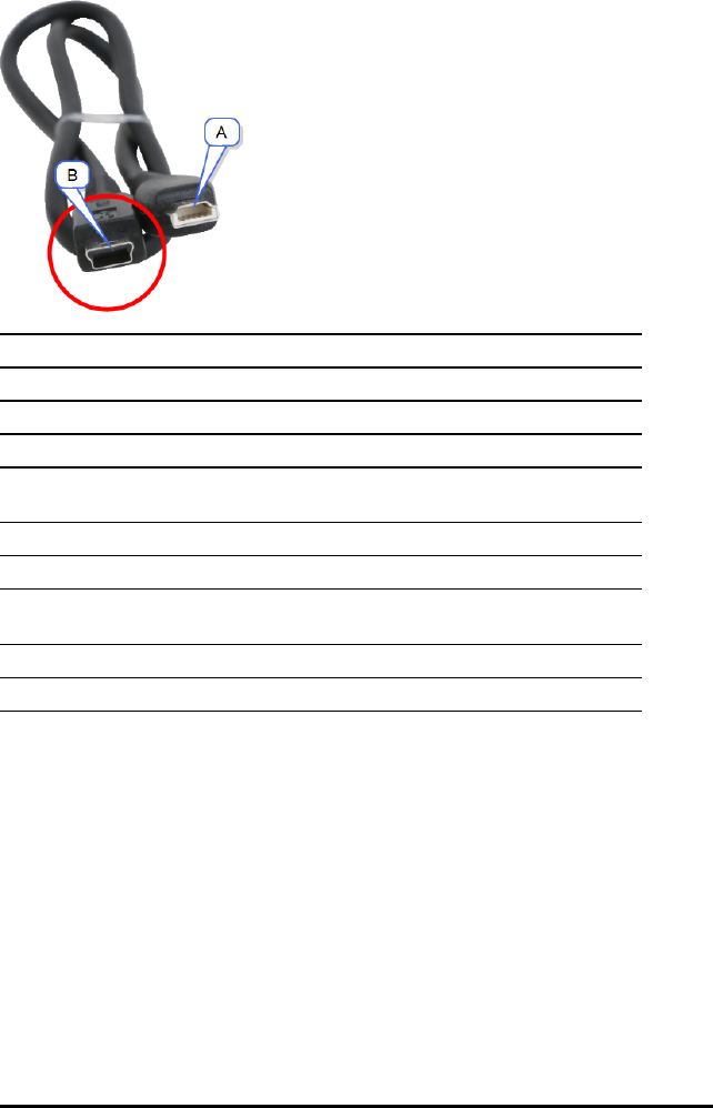
212 TI-Innovator™ Hub Data Sheets
USB Standard A to Mini B Cable Data Sheet
Title USB Standard A to Mini B Cable
TI Item Name STEM/CA/USB20/A
Quantity 1
Included in TI-Innovator™ Hub
Description Connects the Hub to a computer running TI-Nspire™ CX
Software.
Category Accessories
Hub Connection "B" connector to the USB Mini-B port
Assembly
Instructions
Not Applicable
Precautions Not Applicable
Specifications Not Applicable
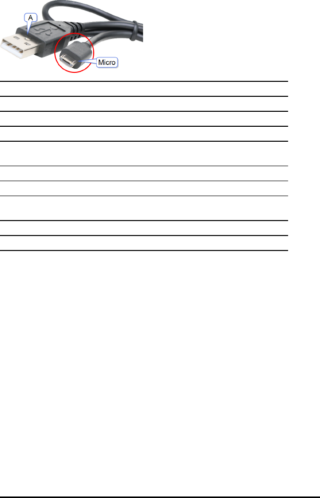
USB Standard A to Micro B Cable Data Sheet
Title USB Standard A to Micro B Cable
TI Item Name XX/CA/USB60/C
Quantity 1
Included in TI-Innovator™ Hub
Description Connects the Hub to a TI approved power source used with
peripherals that require the 5V output port.
Category Accessories
Hub Connection "B" connector to the USB Mini-B port
Assembly
Instructions
Not Applicable
Precautions Not Applicable
Specifications Not Applicable
TI-Innovator™ Hub Data Sheets 213
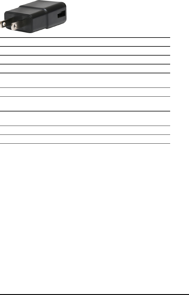
214 TI-Innovator™ Hub Data Sheets
TI Wall Charger Data Sheet
Title TI Wall Charger
TI Item Name XX/AD/9212USB/A
Quantity 1
Included in TI-Innovator™ Hub
Description Wall charger that supplies power through the TI-Innovator™
Hub for connected modules that require additional power.
Category Accessories
Hub Connection Micro connector of the USB Standard A to Micro B Cable to
the PWR connector
Assembly
Instructions
Not Applicable
Precautions Not Applicable
Specifications Not Applicable

External Battery Data Sheet
Title External Battery
TI Item Name STEMBT/A
Quantity 1
Included in External Battery Pack
Description External battery that supplies power through the TI-
Innovator™ Hub for connected modules that require
additional power.
Category Accessories
Hub Connection Micro connector of the USB Standard A to Micro B Cable to
the PWR connector.
Assembly
Instructions
Connect to PWR port on TI-Innovator™ Hub
Precautions Not Applicable
Specifications Not Applicable
TI-Innovator™ Hub Data Sheets 215

216 TI-Innovator™ Rover Setup Guide
TI-Innovator™ Rover Setup Guide
TI-Innovator™ Rover is a two-wheeled programmable robotic vehicle which works with
the TI-Innovator™ Hub with TI LaunchPad™ Board. You communicate with the TI-
Innovator™ Hub and control the Rover through TI Basic programming commands. Built-
in components include two motors, color sensor, ultrasonic ranger, gyroscope, and RGB
LED.
Topics to help you get started include:
•TI-Innovator™ Rover Overview
•What's in the Box
•TI-Innovator™ Rover Setup Requirements
•Preparing TI-Innovator™ Rover
•Connecting TI-Innovator™ Rover
•Exploring the Assembled TI-Innovator™ Rover
•General Precautions

TI-Innovator™ Rover Overview
TI-Innovator™ Rover is a two-wheeled programmable robotic vehicle which works with
the TI-Innovator™ Hub with TI LaunchPad™ Board. You communicate with the Hub and
control the Rover through TI Basic programs on one of these TI products:
• TI CE Family of Graphing Calculators (TI-83 Premium CE, TI-84 Plus CE, and
TI-84 Plus CE-T) with operating system version 5.3 or later installed. You also need
to install or update the Hub App, which contains the Hub menu.
• TI-Nspire™ CX or TI-Nspire™ CX CAS handheld with operating system version 4.5 or
later installed
• TI-Nspire™ computer software version 4.5 or later
Follow this guide to setup your TI-Innovator™ Rover with your TI CE Graphing Calculator
or TI-Nspire™ CX Handheld.
Learn More
Refer to the TI-Innovator™ Technology eGuide for more details.
The eGuide is a web-based source of TI-Innovator™ information, including:
• Programming with the TI CE Family of Graphing Calculators and TI-Nspire™
Technology, including sample programs.
• Available I/O Modules and their commands.
• Available Breadboard components and their commands.
• TI-Innovator™ Rover and its commands.
• Link to update the TI-Innovator™ Sketch software.
• Free classroom activities for Hub and Rover.
To access the eGuide, visit https://education.ti.com/go/eguide/hub/EN.
For a list of precautions to take while using the Rover and its components, refer to
General Precautions (page 228).
TI-Innovator™ Rover Setup Guide 217
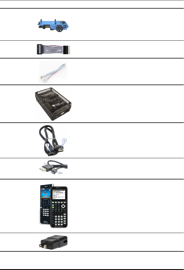
218 TI-Innovator™ Rover Setup Guide
TI-Innovator™ Rover Setup Requirements
To set up your TI-Innovator™ Rover with your TI-Innovator™ Hub and graphing
calculator you will need these materials.
Component Image Description xxxxxxxx
TI-Innovator™
Rover
A two-wheeled programmable robotic
vehicle which works with the Hub.
Breadboard
Ribbon Cable
Connects the Rover to the Hub's
Breadboard Connector.
I2C Cable Connects the Rover to the Hub's I2C
port.
TI-Innovator™
Hub with
TI LaunchPad™
Board
Controls the Rover through TI Basic
programming commands.
USB
Unit-to-Unit
(Mini-A to
Mini-B) Cable
Included with the Hub.
Connects the Hub to a
TI CE Graphing Calculator or a
TI-Nspire™ CX Handheld.
USB Standard A
to Micro Cable
Included with the Hub.
Connects the PWR port of the Rover to a
TI approved power source.
TI CE Graphing
Calculator
or
TI-Nspire™ CX
Handheld
Runs TI Basic programs to send
commands to the Hub.
TIWallCharger Included with the Hub.
Power source for charging the Rover.
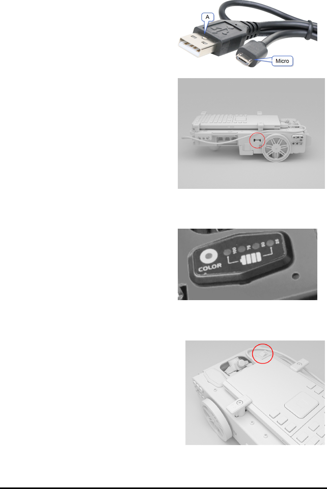
Preparing TI-Innovator™ Rover
Follow these steps to fully charge your TI-Innovator™ Rover.
1. Identify the Micro connector on the USB
Standard A to Micro cable.
2. Insert the Micro connector into the PWR
port on the side of the Rover.
3. Insert the free end of the cable (the "A"
connector) into the USB port on your
computer or TIWallCharger.
Note: The Battery Level Indicator shows
solid green when the battery is fully
charged.
Make sure the TI-Innovator™ Rover is switched OFF before connecting to the
TI-Innovator™ Hub.
▶Flip the On/Off (I/O) switch to the Off (O)
position.
TI-Innovator™ Rover Setup Guide 219
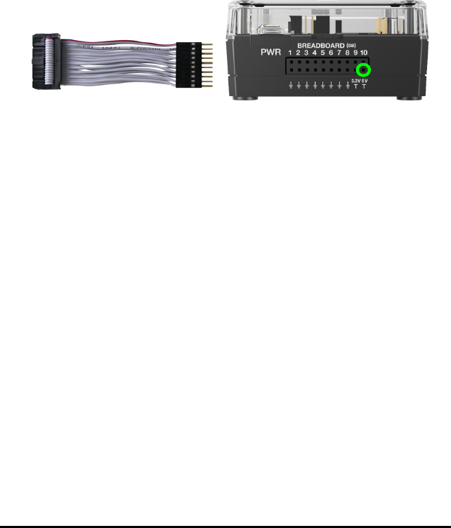
220 TI-Innovator™ Rover Setup Guide
Connecting TI-Innovator™Rover
There are two sets of connection steps to use the TI-Innovator™ Rover.
• First, connect the Rover to the TI-Innovator™ Hub, using the two ribbon cables
provided.
• Second, connect the Hub to a graphing calculator, using the USB Unit-to-Unit
(Mini-A to Mini-B) cable included with the Hub.
Connecting TI-Innovator™ Rover to TI-Innovator™ Hub
1. Insert the Breadboard Ribbon Cable into the Breadboard Connector on the Hub.
Note: It is critical that you insert the cable correctly. Make sure the red (dark) wire
pin is inserted into the 5v hole on the Hub's Breadboard Connector.
2. Carefully guide the attached Ribbon Cable through the opening at the back of the
Rover.
3. As the cable comes through, slide the Hub into place using the Guide Rails.
You will hear a click when the Hub is properly inserted.
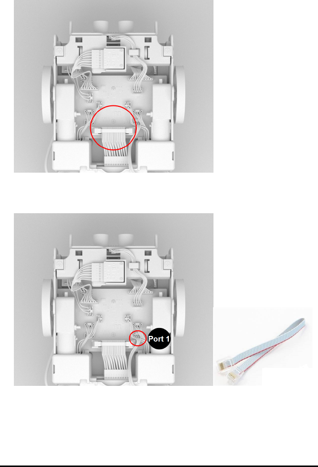
4. Open the two latches on the Rover Circuit Board Ribbon Cable Connector.
5. Align the notch in the ribbon cable with the slot on circuit board connector.
6. Insert the ribbon cable and close the latches.
7. Insert one end of the I2C Cable into the Rover circuit board.
Note: There are two possible I2C ports. Use Port 1.
TI-Innovator™ Rover Setup Guide 221
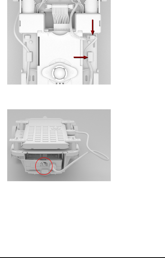
222 TI-Innovator™ Rover Setup Guide
8. Insert the slack I2C Cable into the side rails.
9. Align the tab on the I2C Cable with the top of the I2C port.
10. Insert the free end of the I2C Cable connector into the I2C port at the back of the
Hub.
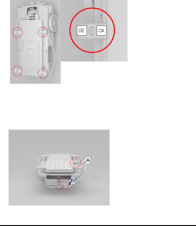
Connecting TI-Innovator™ Hub to a Graphing Calculator
1. Turn the Rover right side up.
2. Lift and turn the Calculator Holder Pegs so that they are parallel with the side of
the Rover.
3. Place the TI CE Graphing Calculator or TI-Nspire™ CX Handheld on the platform
with the screen toward the Marker Holder.
4. Turn the pegs so that the CE or CX Label is positioned inward to match the graphing
calculator.
The pegs will snap into place when they are positioned correctly.
Caution: Do not turn the Calculator Holder Pegs without lifting them first. They
could break.
5. Identify the "B" connector on the USB Unit-to-Unit (Mini-A to Mini-B) cable. Each end
of this cable is embossed with a letter.
6. Insert the "B" connector into the DATA port on the Hub.
7. Insert the free end of the cable (the "A" connector) into the USB port on the
graphing calculator.
TI-Innovator™ Rover Setup Guide 223
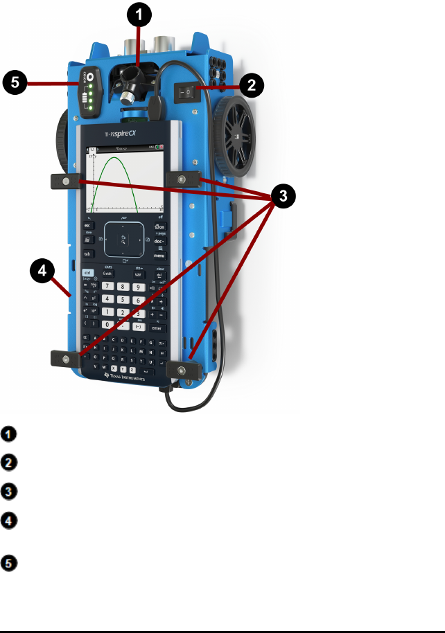
224 TI-Innovator™ Rover Setup Guide
Exploring the Assembled TI-Innovator™ Rover
Explore all sides of the TI-Innovator™ Rover when assembled with the TI-Innovator™
Hub and TI CE Graphing Calculator or TI-Nspire™ CX Handheld connected.
Top Side of the Rover
Marker Holder - Holds a marker to draw paths.
ON/OFF (I/O) Switch - Turns the Rover ON (–) or OFF (O).
Calculator Holder Pegs - Secures a graphing calculator to the calculator platform.
Calculator Platform - Holds either a TI CE Graphing Calculator or
TI-Nspire™ CX Handheld.
LED Panel (RGB LED/Battery Level Indicator) - Displays programmable feedback
through the Red-Green-Blue (RGB) LED, and displays battery charge level.
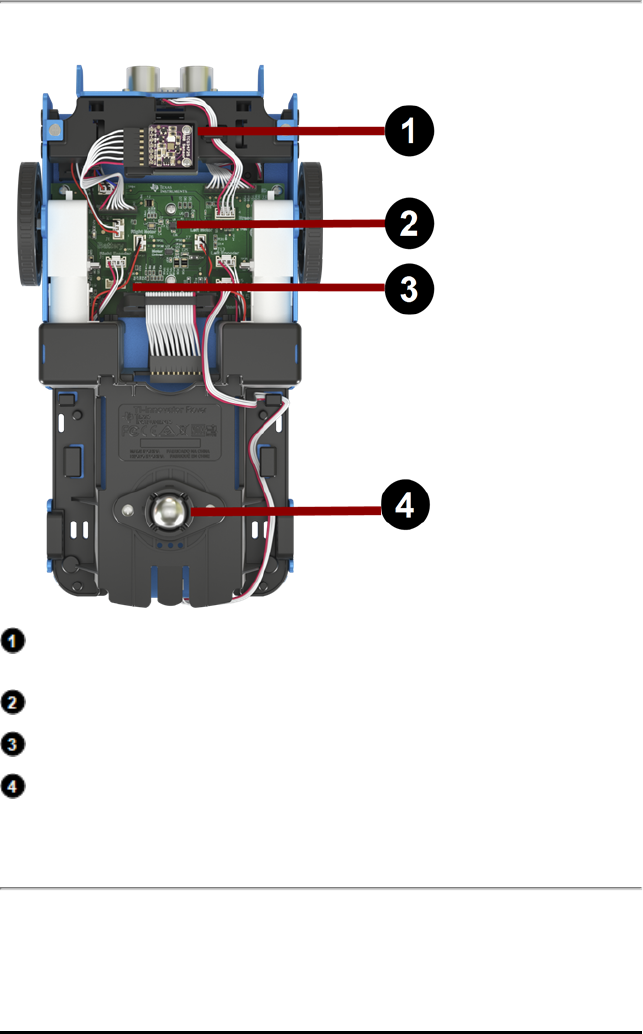
Bottom Side of the Rover
Color Sensor - Bottom-mounted color sensor detects the color of the surface. Can
also detect gray-level scale of black (0) to white (255).
Gyroscope - Measures or maintains orientation.
I2Cexpansion port.
Ball Caster - Provides smooth movement on hard surface.
Note: Not recommended for use on carpet.
Caution: If you dislodge or disconnect any of the cables, use this image as a reference
for correct hookups.
TI-Innovator™ Rover Setup Guide 225
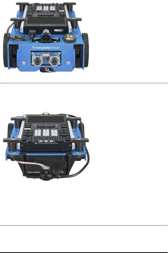
226 TI-Innovator™ Rover Setup Guide
Front Side of the Rover
Ultrasonic Ranger - Measures distance to obstacles.
Back Side of the Rover
Guide Rails - Allows the Hub to slide easily into the Rover and connect to the Rover
circuit board.
Note: With the TI-Innovator™ Hub inserted, access a sensor and two ports.
•Light Brightness Sensor - Reads as "BRIGHTNESS" in Hub command strings.
•I2Cport - Uses I2C cable to connect the Hub to the Rover circuit board.
•DATAMini-B port - Uses USB Unit-to-Unit (Mini-A to Mini-B) Cable to connect the
Hub to a Graphing Calculator.
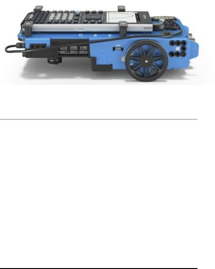
Right Side of the Rover
Access on the Rover:
•PWR port - Uses USB Standard A to Micro auxiliary power cable when charging the
Rover's Rechargeable battery.
•Front and Back Mounts - For adding structures to the Rover using interlocking
plastic blocks.
Note: With the Hub inserted, access three ports for controlling output modules.
•OUT1 and OUT2 provide 3.3V power.
•OUT3 provides 5V power.
TI-Innovator™ Rover Setup Guide 227
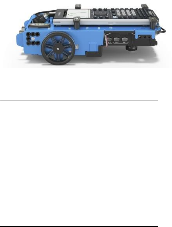
228 TI-Innovator™ Rover Setup Guide
Left Side of the Rover
Access on the Rover:
•Front and Back Mounts - For adding structures to the Rover using interlocking
plastic blocks.
Note: With the Hub inserted, access three ports for collecting data or status from input
modules.
•IN1 and IN2 provide 3.3V power.
•IN3 provides 5V power.
General Precautions
TI-Innovator™Rover
• Do not expose the Rover to temperatures above 140˚F (60˚C).
• Do not disassemble or mistreat the Rover.
• Do not put anything heavier than 1 Kg or 2.2 lbs on the Rover platform.
• Use only the USB cables provided with the TI-Innovator™ Hub.
• Use only the Ribbon cables provided with the Rover.
• Use only the TI provided wall charger included with the Hub.
• The front-mounted Ultrasonic Ranger will detect objects within 4 meters of the
Rover. For best results make sure the object's surface is bigger than a folder. If
used to detect small objects, such as a cup, place the Rover within 1 meter of the
object.
• For best results, leave the Slide Case off of your graphing calculator.
• For best performance, use Rover on the floor, not on tables. Damage may occur
from Rover falling off a table.
• For best performance, use Rover on a hard surface. Carpet may cause the Rover
wheels to catch or drag.

• Do not turn the Holder pegs on the Calculator Platform without lifting them first.
They could break.
• When securing a marker in the Marker Holder avoid over-tightening the screw.
• Do not use the marker as a lever to pull or push the Rover.
• Do not unscrew the case enclosure on the bottom of the Rover. Encoders have
sharp edges that should not be exposed.
• Do not move Rover after executing a program. The internal gyroscope may
unintentionally try to get the Rover back on track using the initial location.
• When inserting the Breadboard Ribbon Cable into the Hub Breadboard Connector, it
is critical that you insert the cable correctly. Make sure the red (dark) wire pin is
inserted into the 5v hole on the Hub's Breadboard Connector.
TI-Innovator™ Rover Setup Guide 229

230 TI-Innovator™ Rover Setup Guide
Caution: If you dislodge or disconnect any of the cables, use this image as a reference
for correct hookups.
Reference to Bottom View

TI-Innovator™ Rover Commands version 1.2
Prerequisite: Use the Send "Connect RV" Command First
The "CONNECT RV" command needs to be used first when using the Rover. The
"CONNECT RV" command configures the TI-Innovator™ Hub software to work with the
TI-Innovator™ Rover.
It establishes the connections to the various devices on the Rover – two motors, two
encoders, one gyroscope, one RGB LED and one color sensor. It also clears the various
counters and sensor values. The optional ‘MOTORS’ parameter configures only the
motors and allows direct control of motors without the additional peripherals.
CONNECT RV - initializes the hardware connections.
• Connects RV and inputs and outputs built into the RV.
• Resets the Path and the Grid Origin.
• Sets the units per meter to default value of 10. Default Grid unit = 10cm.
Named RV Subsystems
The RV object contains several subsystems that are directly addressed by name. These
subsystems consist of the wheels, and sensors that let the Rover sense the world.
The subsystems are listed by name in the following table.
Subsystem Name Description of Subsystem
RV The RV object as a whole.
RV.COLOR The tri-color RGB LED on the top surface of the
Rover can be controlled through user programs
to display any color combination.
RV.COLORINPUT The color sensor is on the bottom of the Rover
and is used to detect the color of the surface.
RV.RANGER The front-facing ultrasonic distance sensor.
Returns measurements in meters. ~10.00
meters means no obstacle was detected.
RV.ENCODERGYRO The rotary encoders – one on each motor –
measure the distance traveled by the Rover.
The left and right encoder, coupled with the
gyroscope and operating time information.
RV.GYRO The gyroscope is used to maintain the heading
of Rover while it’s in motion. It can also be
used to measure the change in angle during
turns.
RV.MOTOR.L Left wheel motor and control for direct control
(advanced) use.
RV.MOTOR.R Right wheel motor and control for direct
control (advanced) use.
TI-Innovator™ Rover Commands version 1.2 1

2 TI-Innovator™ Rover Commands version 1.2
Subsystem Name Description of Subsystem
RV.MOTORS Both the LEFT and RIGHT motor, managed as a
single object for direct control (advanced) use.
Rover Command Categories
The Rover commands fall into two categories:
1. Queued execution: All of the Rover motion commands – FORWARD, BACKWARD,
LEFT, RIGHT, ANGLE – are queued on the TI-Innovator Hub. They may execute at a
future time.
2. Immediate execution: Other commands – like the ones to read the sensors or set
the RGB LED on the Rover – are executed immediately.
This means that certain statements in your program will execute before statements
that appear earlier in the program especially if the latter commands are part of the
queued family.
For example, in the program below, the RGB LED will turn RED before the Rover stops
moving:
Send "SET RV.COLOR 255 0 255" – immediately executed
Send "RV FORWARD 5" – queued command
Send "RV LEFT 45" – queued command
Send "RV RIGHT 90" – queued command
Send "SET RV.COLOR 255 0 0" – immediately executed
Example:
To change color after a "FORWARD" movement, use "TIME" parameter with "WAIT".
Send "RV FORWARD TIME 5"
WAIT 5
Send "SET RV.COLOR 255 0 255"
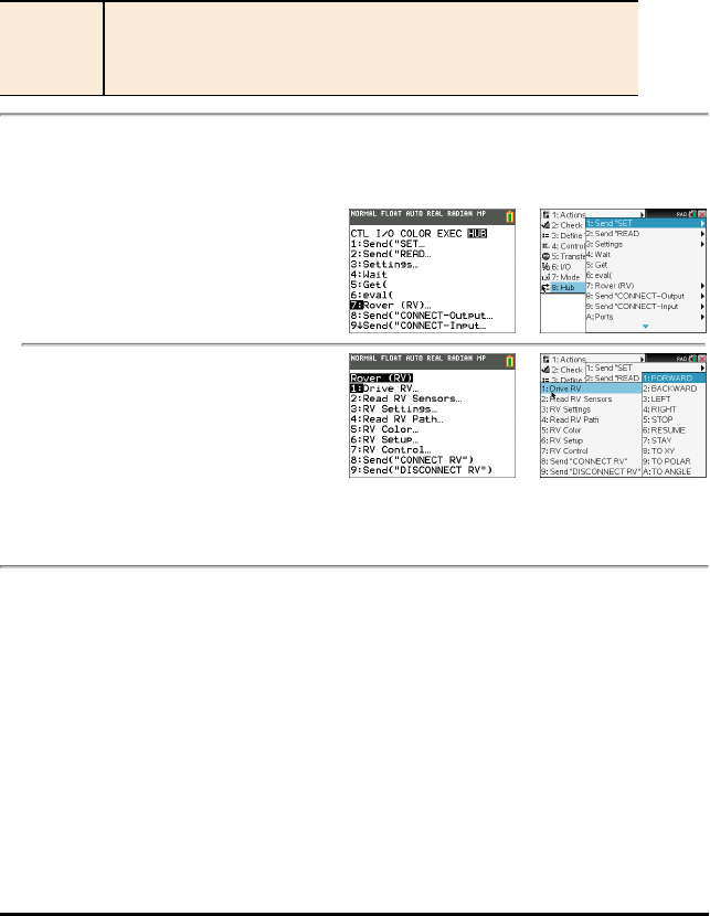
RV Commands, Code Samples, and Syntax
The following examples show how various commands for the RV are used. Anywhere a
SET command is used, the SET may be left off (optional use).
Code Samples
When you see "Code Sample" in a command table, this "Code Sample" may be copied
and pasted as is to send to your graphing calculator to use in your calculations.
Example:
Code
Sample:
Send ("RV FORWARD 5")
Send ("RV FORWARD SPEED 0.2 M/S TIME 10")
TI-Innovator™ Rover Menu
Rover (RV)... TI-84 Plus CE TI-Nspire™ CX
•Drive RV…
•Read RV Sensors…
•RV Settings…
•Read RV Path…
•RV Color…
•RV Setup…
•RV Control…
•Send("CONNECT RV")
•Send("DISCONNECT RV")
TI-Innovator™ Rover Commands version 1.2 3
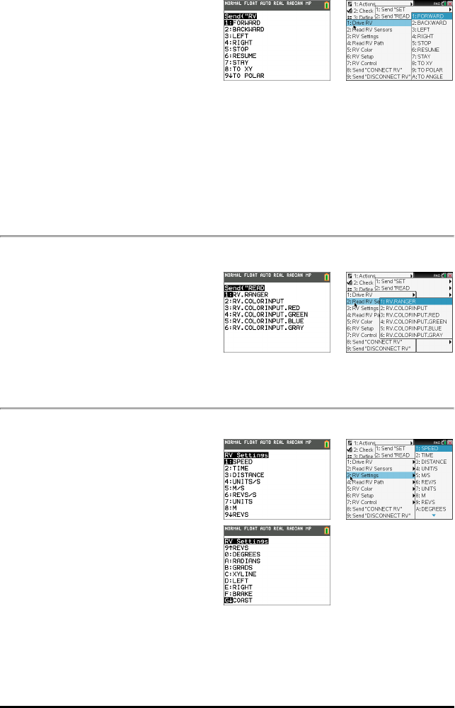
4 TI-Innovator™ Rover Commands version 1.2
•Drive RV…
–Send("RV
–FORWARD
–BACKWARD
–LEFT
–RIGHT
–STOP
–RESUME
–STAY
–TO XY (INACTIVE in v1.2
Release)
–TO POLAR (INACTIVE in
v1.2 Release)
–TO ANGLE
TI-84 Plus CE TI-Nspire™ CX
•Read RV Sensors…
–Send"READ"
–RV.RANGER
–RV.COLORINPUT
–RV.COLORINPUT.RED
–RV.COLORINPUT.GREEN
–RV.COLORINPUT.BLUE
–RV.COLORINPUT.GRAY
TI-84 Plus CE TI-Nspire™ CX
•RV Settings...
–RV Settings
–SPEED
–TIME
–DISTANCE
–UNIT/S
–M/S
–REV/S
–UNITS
–M
–REVS
–DEGREES
–RADIANS
–GRADS
TI-84 Plus CE TI-Nspire™ CX
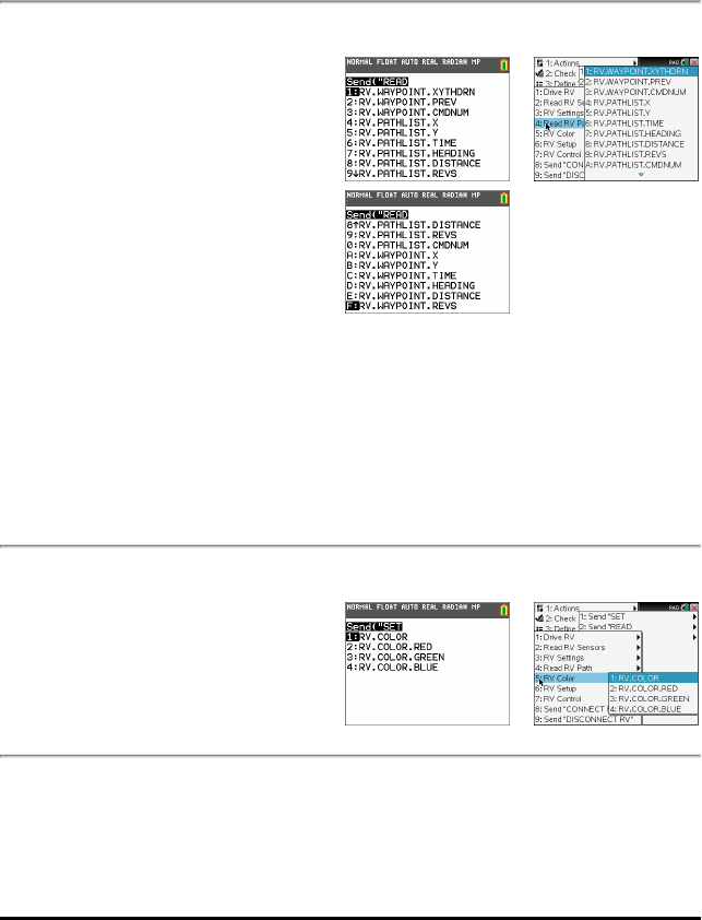
–XYLINE
–LEFT
–RIGHT
–BRAKE
–COAST
–CW
–CCW
•Read RV Path…
–Send "READ
–RV.WAYPOINT.XYTHDRN
–RV.WAYPOINT.PREV
–RV.WAYPOINT.CMDNUM
–RV.PATHLIST.X
–RV.PATHLIST.Y
–RV.PATHLIST.TIME
–RV.PATHLIST.HEADING
–RV.PATHLIST.DISTANCE
–RV.PATHLIST.REVS
–RV.PATHLIST.CMDNUM
–RV.WAYPOINT.X
–RV.WAYPOINT.Y
–RV.WAYPOINT.TIME
–RV.WAYPOINT.HEADING
–RV.WAYPOINT.DISTANCE
–RV.WAYPOINT.REVS
TI-84 Plus CE TI-Nspire™ CX
•RV Color…
–Send "SET
–RV.COLOR
–RV.COLOR.RED
–RV.COLOR.GREEN
–RV.COLOR.BLUE
TI-84 Plus CE TI-Nspire™ CX
•RV Setup…
–Send "SET
–RV.POSITION
TI-84 Plus CE TI-Nspire™ CX
TI-Innovator™ Rover Commands version 1.2 5
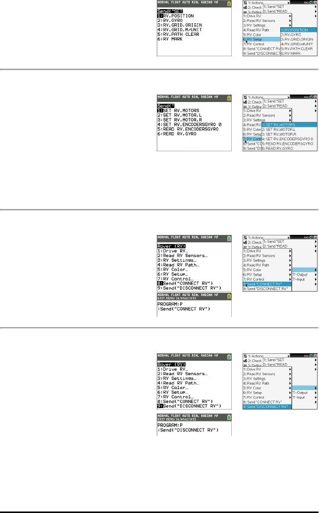
6 TI-Innovator™ Rover Commands version 1.2
–RV.GYRO
–RV.GRID.ORIGIN
–RV.GRID.M/UNIT
–RV.PATH CLEAR
–RV MARK
•RV Control…
–Send "
–SET RV.MOTORS
–SET RV.MOTOR.L
–SET RV.MOTOR.R
–SET RV.ENCODERSGYRO
0
–READ
RV.ENCODERSGYRO
–READ RV.GYRO
TI-84 Plus CE TI-Nspire™ CX
•Send "CONNECT RV"
–Send "CONNECT RV"
–CONNECT RV
TI-84 Plus CE TI-Nspire™ CX
•Send "DISCONNECT RV"
–Send "DISCONNECT RV"
–DISCONNECT RV
TI-84 Plus CE TI-Nspire™ CX
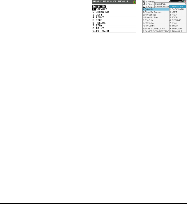
Drive RV...
RV Drive Command Families
• Base Drive Commands (in the spirit of Turtle Graphics)
- FORWARD, BACKWARD, RIGHT, LEFT, STOP, STAY
• Math Coordinate Drive Commands
- Turn to Angle
Note: Drive commands have options for Speed, Time and Distance as appropriate
• See RV Settings for Machine-Level Control Commands
- Set Left and Right Motor values for direction (CW/CCW) and level (0-255,Coast)
- Read accumulated values for wheel encoder edges and gyro heading change.
•Drive RV…
– Send("RV
–FORWARD
–BACKWARD
–LEFT
–RIGHT
–STOP
–RESUME
–STAY
–TO XY (INACTIVE in v1.2
Release)
–TO POLAR (INACTIVE in
v1.2 Release)
–TO ANGLE
TI-84 PlusCE TI-Nspire™ CX
TI-Innovator™ Rover Commands version 1.2 7

8 TI-Innovator™ Rover Commands version 1.2
RV FORWARD
Command: RV FORWARD
Command
Syntax:
RV FORWARD [[SPEED s] [DISTANCE d] [TIME t]]
Code
Samples:
Send ("RV FORWARD 0.5 M")
Send ("RV FORWARD SPEED 0.22 M/S TIME 10")
[SET] RV FORWARD
[SET] RV FORWARD [DISTANCE] d [M|UNIT|REV]
[SET] RV FORWARD [DISTANCE] d [M|UNIT|REV]
SPEED s.ss [M/S|[UNIT/S]|REV/S]
[SET] RV FORWARD [DISTANCE] d [M|UNIT|REV]
TIME t
[SET] RV FORWARD SPEED s [M/S|UNIT/S|REV/S]
[TIME t]
[SET] RV FORWARD TIME t [SPEED s.ss
[M/S|[UNIT/S]|REV/S]]
Range: N/A
Describe: RV moves forward a given distance (default 0.75 m). Default distance if
specified is in UNIT (grid units). Optional M=meters, UNIT=grid-unit,
REV=wheel-revolution.
Default speed is 0.20 m/sec, max is 0.23 m/sec, min is 0.14 m/sec.
Speed may be given and specified in meters/second, unit/second,
revolutions/second.
Result: Action to make the RV move in a forward direction
Type or
Addressable
Component:
Control
Note: This Rover control command is sent and executed in a queue.

RV BACKWARD
Command: RV BACKWARD
Command
Syntax:
RV BACKWARD
Code
Sample:
Send("RV BACKWARD 0.5 M")
Send("RV BACKWARD SPEED 0.22 M/S TIME 10")
[SET] RV BACKWARD
[SET] RV BACKWARD [DISTANCE] d [M|UNIT|REV]
[SET] RV BACKWARD [DISTANCE] d [M|UNIT|REV]
SPEED s.ss [M/S|[UNIT/S]|REV/S]
[SET] RV BACKWARD [DISTANCE] d [M|UNIT|REV]
TIME t
[SET] RV BACKWARD SPEED s.ss
[M/S|UNIT/S|REV/S] [TIME t]
[SET] RV BACKWARD TIME t
[SPEED s.ss [M/S|UNIT/S|REV/S]]
Range: N/A
Describe: RV moves backward a given distance (default 0.75 m). Default distance if
specified is in UNIT (grid units). Optional M=meters, UNIT=grid-unit,
REV=wheel-revolution.
Default speed is 0.20 m/sec, max is 0.23 m/sec, min is 0.14 m/sec.
Speed may be given and specified in meters/second, unit/second,
revolutions/second.
Result: Action to make the RV move in a backward direction.
Type or
Addressable
Component:
Control
Note: This Rover control command is sent and executed in a queue.
TI-Innovator™ Rover Commands version 1.2 9
10 TI-Innovator™ Rover Commands version 1.2
RV LEFT
Command: RV LEFT
Command
Syntax:
RV LEFT
Code
Sample:
Send "RV LEFT"
[SET] RV LEFT [ddd [DEGREES]]
[SET] RV LEFT [rrr RADIANS]
[SET] RV LEFT [ggg GRADIANS]
Range: N/A
Describe: Default turn is 90 degrees unless DEGREES, RADIANS, or GRADIANS
keyword is present, and then the value is converted internally to degrees
format from the specified units. Value given is ranged to a value between
0.0 and 360.0 degrees. The turn will be executed as a SPIN motion.
Result: Turn Rover to the LEFT.
Type or
Addressable
Component:
Control
Note: This Rover control command is sent and executed in a queue.
RV RIGHT
Command: RV RIGHT
Command
Syntax:
RV RIGHT
Code
Sample:
Send "RV RIGHT"
[SET] RV RIGHT [ddd [DEGREES]]
[SET] RV RIGHT [rrr RADIANS]
[SET] RV RIGHT [ggg GRADIANS]
Range: N/A
Describe: Default turn is 90 degrees unless DEGREES, RADIANS, or GRADIANS
keyword is present, and then the value is converted internally to degrees
format from the specified units. Value given is ranged to a value between
0.0 and 360.0 degrees. The turn will be executed as a SPIN motion.
Result: Turn Rover to the RIGHT.
Type or Control

Command: RV RIGHT
Addressable
Component:
Note: This Rover control command is sent and executed in a queue.
RV STOP
Command: RV STOP
Command
Syntax:
RV STOP
Code
Sample:
Send "RV STOP"
[SET] RV STOP
[SET] RV STOP CLEAR
Range: N/A
Describe: The RV will stop any current movement immediately. That movement can
be resumed from where it left off with a RESUME operation. Any
movement commands will cause the queue to flush immediately, and begin
the just-posted new movement operation
Result: Stop processing Rover commands from the command queue, and leave
pending operations in the queue. (immediate action). Queue can be
resumed by RESUME.The RV will stop any current movement
immediately. That movement can be resumed from where it left off with a
RESUME operation. Any movement commands will cause the queue to
flush immediately, and begin the just-posted new movement operation.
Stop processing Rover commands from the command queue, and flush
any pending operations left in the queue. (immediate action).
Type or
Addressable
Component:
Control
Note: This Rover control command is executed immediately.
RV RESUME
Command: RV RESUME
Command
Syntax:
RV RESUME
TI-Innovator™ Rover Commands version 1.2 11
12 TI-Innovator™ Rover Commands version 1.2
Command: RV RESUME
Code
Sample:
Send "RV RESUME"
[SET] RV RESUME
Range: N/A
Describe: Enable processing of Rover commands from the command queue.
(immediate action), or resume (see RV STAY) operation.
Result: Resume operation.
Type or
Addressable
Component:
Control
Note: This Rover control command is sent and executed in a queue.
RV STAY
Command: RV STAY
Command
Syntax:
RV STAY
Code
Sample:
Send "RV STAY"
[SET] RV STAY [[TIME] s.ss]
Range: N/A
Describe: Tells RV to "stay" in place for an optionally specified amount of time in
seconds.
Default is 30.0 seconds.
Result: RV stays in position.
Type or
Addressable
Component:
Control
Note: This Rover control command is sent and executed in a queue.
RV TO XY (INACTIVE in v1.2 Release)
RV TO POLAR (INACTIVE in v1.2 Release)

RV TO ANGLE
Command: RV TO ANGLE
Command
Syntax:
RV TO ANGLE
Code
Sample:
Send "RV TO ANGLE"
[SET] RV TO ANGLE rr.rr
[[DEGREES]|RADIANS|GRADIANS]
Range: N/A
Describe:
Result: Spins the RV to the specified angle from current heading.
Type or
Addressable
Component:
Control
Note: This Rover control command is sent and executed in a queue.
TI-Innovator™ Rover Commands version 1.2 13
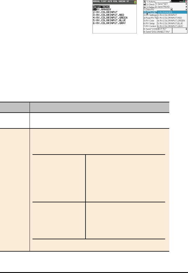
14 TI-Innovator™ Rover Commands version 1.2
READ RV Sensors...
SEND("Read Sensor Commands
• Reading of low level sensors for learning foundations of robotics.
•Read RV Sensors…
– Send("READ
–RV.RANGER
–RV.COLORINPUT
–RV.COLORINPUT.RED
–RV.COLORINPUT.GREEN
–RV.COLORINPUT.BLUE
–RV.COLORINPUT.GRAY
•RV.RANGER: Returns value in
Meters.
•RV.COLORINPUT: Reads color
sensor that is built into the RV.
RV.RANGER
Command: RV.RANGER
Command
Syntax:
RV.RANGER
Code
Sample:
Send("READ RV.RANGER")
Get(R)
Connects the Rover
Vehicle to the TI-
Innovator™ Hub. This
establishes connections
with the motor driver,
color sensor, gyroscope,
ultrasonic ranger, and
proximity sensors.
CONNECT RV
Returns the current
distance from the front of
the RV to an obstacle. If
there is no obstacle
detected, a range of
10.00 meters is reported
READ RV.RANGER
Get(R)
Command: RV.RANGER
Range: N/A
Describe: The front-facing ultrasonic distance sensor. Returns measurements in
meters. ~10.00 meters means no obstacle was detected.
Result: Returns value in Meters.
Type or
Addressable
Component:
Sensor
Note: This Rover sensor command is executed immediately.
RV.COLORINPUT
Command: RV.COLORINPUT
Command
Syntax:
RV.COLORINPUT
Code
Sample:
Send("READ RV.COLORINPUT")
Get(C)
Range: 1 thru 9
Describe: Bottom-mounted color sensor detects the color of the surface. Can also
detect gray-level scale of black (0) to white (255).
Result: Returns current color sensor information.
The return value is in the 1 – 9 range which maps to the colors below:
Color Return value
Red 1
Green 2
Blue 3
Cyan 4
Magenta 5
Yellow 6
Black 7
White 8
Gray 9
Type or
Addressable
Component:
Sensor
Note: This Rover sensor command is executed immediately.
TI-Innovator™ Rover Commands version 1.2 15
16 TI-Innovator™ Rover Commands version 1.2
RV.COLORINPUT.RED
Command: RV.COLORINPUT.RED
Command
Syntax:
RV.COLORINPUT.RED
Code
Sample:
Send("READ RV.COLORINPUT.RED")
Get(R)
Range: 0 - 255
Describe: Detect intensity of individual red components of surface.
The results are in 0-255 range.
Result: Returns current color sensor "red value".
Type or
Addressable
Component:
Sensor
Note: This Rover sensor command is executed immediately.
RV.COLORINPUT.GREEN
Command: RV.COLORINPUT.GREEN
Command
Syntax:
RV.COLORINPUT.GREEN
Code
Sample:
Send("READ RV.COLORINPUT.GREEN")
Get(G)
Range: 0 - 255
Describe: Detect intensity of individual green components of surface.
The results are in 0-255 range.
Result: Returns current color sensor "green" value.
Type or
Addressable
Component:
Sensor
Note: This Rover sensor command is executed immediately.

RV.COLORINPUT.BLUE
Command: RV.COLORINPUT.BLUE
Command
Syntax:
RV.COLORINPUT.BLUE
Code
Sample:
Send("READ RV.COLORINPUT.BLUE")
Get(B)
Range: 0 - 255
Describe: Detect intensity of individual blue components of surface.
The results are in 0-255 range.
Result: Returns current color sensor "blue" value.
Type or
Addressable
Component:
Sensor
Note: This Rover sensor command is executed immediately.
RV.COLORINPUT.GRAY
Command: RV.COLORINPUT.GRAY
Command
Syntax:
RV.COLORINPUT.GRAY
Code
Sample:
Send("READ RV.COLORINPUT.GRAY")
Get(G)
Range: 0 - 255
Describe: Detect grayness of surface.
The result will be in 0-255 range.
Result: Returns an interpolated "grayscale" value based on 0.3*red + 0.59*green
+ 0.11*blue
0-black, 255 - white.
Type or
Addressable
Component:
Sensor
Note: This Rover sensor command is executed immediately.
TI-Innovator™ Rover Commands version 1.2 17

18 TI-Innovator™ Rover Commands version 1.2
RV Settings...
RV Settings Commands
Settings menu for Rover contains other commands that support RV commands such as
FORWARD or BACKWARD.
•RV Settings...
– RV Settings
– SPEED
– TIME
– DISTANCE
– UNIT/S
– M/S
– REV/S
– UNITS
– M
– REVS
– DEGREES
– RADIANS
– GRADS
– XYLINE
– LEFT
– RIGHT
– BRAKE
– COAST
– CW
– CCW

Read RV Path…
Reading WAYPOINT and PATH
Tracking the RV’s Path
In order to support analysis of the Rover during and after a run, the sketch will
automatically measure the following information for each Drive command:
• X Coordinate on virtual grid
• Y Coordinate on virtual grid
• Time in seconds that the current command has been executing.
• Distance in coordinate units for the path segment.
• Heading in degrees (absolute terms measured Counter Clockwise with the X-axis as
0 degrees.
• Revolutions by the wheel in executing the current command
• Command number, tracks the number of commands executed, begins with 0.
The Path values will be stored in lists, starting with the segments associated with the
earliest commands and going to the segments associated with the latest commands.
The drive command in progress, the WAYPOINT, will repeatedly update the last
element in the Path lists as the Rover progresses toward the last waypoint.
When a drive command is completed a new waypoint is initiated and the dimension of
the Path lists are incremented.
Note: This implies that when all the drive commands in the queue are completed
that another waypoint for the stopped state is automatically started. This is similar
to the initial position where the RV is stationary and counting time.
Max number of waypoints: 80
TI-Innovator™ Rover Commands version 1.2 19
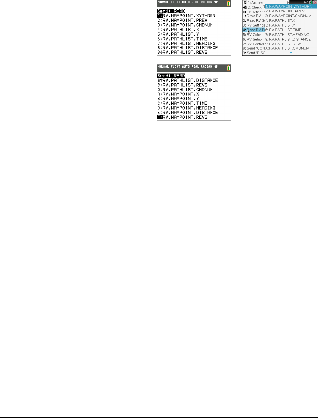
20 TI-Innovator™ Rover Commands version 1.2
RV Position and Path
• Ability to read X,Y coordinate, Heading, Time and Distance for each drive command
in execution.
• Will store path history in lists for plotting and analysis
Note: Coordinate grid scale can be set by the user, default is 10cm per unit. The user
will have options to set the origin of the grid.
•Read RV Path…
– Send("READ
–RV.WAYPOINT.XYTHDRN
–RV.WAYPOINT.PREV
–RV.WAYPOINT.CMDNUM
–RV.PATHLIST.X
–RV.PATHLIST.Y
–RV.PATHLIST.TIME
–RV.PATHLIST.HEADING
–RV.PATHLIST.DISTANCE
–RV.PATHLIST.REVS
–RV.PATHLIST.CMDNUM
–RV.WAYPOINT.X
–RV.WAYPOINT.Y
–RV.WAYPOINT.TIME
–RV.WAYPOINT.HEADING
–RV.WAYPOINT.DISTANCE
–RV.WAYPOINT.REVS
TI-84 PlusCE TI-Nspire™ CX

RV.WAYPOINT.XYTHDRN
Command: RV.WAYPOINT.XYTHDRN
Command
Syntax:
RV.WAYPOINT.XYTHDRN
Code
Sample:
Send("READ RV.WAYPOINT.XYTHDRN")
Example: Getting the distance traveled toward the current way-point from the last
way-point
Code
Sample:
Send("READ RV.WAYPOINT.XYTHDRN")
Get(L1)
(L1)(5)->D
Range: N/A
Describe: READ RV.WAYPOINT.XYTHDRN - read the x-coord, y-coord, time,
heading, distance traveled, number of wheel revolutions, command
number of the current waypoint. Returns a list with all these values as
elements.
Result: Return list of current way-point X, Y coordinates, Time, Heading, Distance,
Revolutions, and command number.
Type or
Addressable
Component:
Returns Data
RV.WAYPOINT.PREV
Command: RV.WAYPOINT.PREV
Command
Syntax:
RV.WAYPOINT.PREV
Code
Sample:
Send("READ RV.WAYPOINT.PREV")
Example: Getting the distance traveled during the previous way-point.
Code
Sample:
Send("READ RV.WAYPOINT.PREV")
Get(L1)
(L1)(5)->D
TI-Innovator™ Rover Commands version 1.2 21
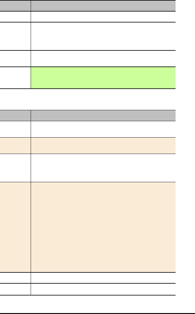
22 TI-Innovator™ Rover Commands version 1.2
Command: RV.WAYPOINT.PREV
Range: N/A
Describe: READ RV.WAYPOINT.PREV - read the x-coord, y-coord, time, heading,
distance traveled, number of wheel revolutions, command number of the
previous waypoint. Returns a list with all these values as elements.
Result: Return list of the previous way-point X, Y coordinates, time, heading,
distance, revolutions, and command number.
Type or
Addressable
Component:
Returns Data
RV.WAYPOINT.CMDNUM
Command: RV.WAYPOINT.CMDNUM
Command
Syntax:
RV.WAYPOINT.CMDNUM
Code
Sample:
Send("READ RV.WAYPOINT.CMDNUM")
Example: Program to determine if a drive command has completed without
referring to a specific command number.
Note: the Wait is intended to increase the probability of catching a
difference in the Command Number.
Code
Sample:
Send("RV FORWARD 10")
Send("READ RV.WAYPOINT.CMDNUM")
Get(M)
M->N
While M=N
Send("READ RV.WAYPOINT.CMDNUM")
Get(N)
End
Disp "Drive Command is completed"
Range: N/A
Describe: READ RV.WAYPOINT.CMDNUM - returns the last command number of

Command: RV.WAYPOINT.CMDNUM
the current waypoint.
Result: Returns a value of 0 if the RV is currently "working" on a command and is
either in motion, or running a STAY operation. This command will return a
value of 1 when ALL queued operations are completed, nothing is
remaining in the command queue, and the current operation has
completed (and immediately after CONNECT RV).
Type or
Addressable
Component:
Returns Data
RV.PATHLIST.X
Command: RV.PATHLIST.X
Command
Syntax:
RV.PATHLIST.X
Code
Samples:
Send("READ RV.PATHLIST.X")
Example: Program to plot the RV path on the graph screen
Code
Samples:
Plot1(xyLine, L1, L2,▫,BLUE)
Send("READ RV.PATHLIST.X")
Get(L1)
Send("READ RV.PATHLIST.Y")
Get(L2)
DispGraph
Range: N/A
Describe: READ RV.PATHLIST.X - returns a list of X values from the beginning to and
including the current Waypoint X value.
Result: Return list of X coordinates traversed since last RV.PATH CLEAR or initial
CONNECT RV.
Type or
Addressable
Component:
Returns Data
TI-Innovator™ Rover Commands version 1.2 23

24 TI-Innovator™ Rover Commands version 1.2
RV.PATHLIST.Y
Command: RV.PATHLIST.Y
Command
Syntax:
RV.PATHLIST.Y
Code
Sample:
Send("READ RV.PATHLIST.Y")
Example: Program to plot the RV path on the graph screen
Code
Sample:
Plot1(xyLine, L1, L2,▫,BLUE)
Send("READ RV.PATHLIST.Y")
Get(L1)
Send("READ RV.PATHLIST.X")
Get(L2)
DispGraph
Range: N/A
Describe: READ RV.PATHLIST.Y - returns a list of Y values from the beginning to and
including the current Waypoint Y value.
Result: Return list of Y coordinates traversed since last RV.PATH CLEAR or initial
CONNECT RV.
Type or
Addressable
Component:
Returns Data
RV.PATHLIST.TIME
Command: RV.PATHLIST.TIME
Command
Syntax:
RV.PATHLIST.TIME
Code
Sample:
Send "READ RV.PATHLIST.TIME"
Range: N/A
Describe: READ RV.PATHLIST.TIME - returns a list of the time in seconds from the
beginning to and including the current Waypoint time value.

Command: RV.PATHLIST.TIME
Result: Return list of cumulative travel times for each successive way-point.
Type or
Addressable
Component:
Returns Data
RV.PATHLIST.HEADING
Command: RV.PATHLIST.HEADING
Command
Syntax:
RV.PATHLIST.HEADING
Code
Sample:
Send "READ RV.PATHLIST.HEADING"
Range: N/A
Describe: READ RV.PATHLIST.HEADING - returns a list of the headings from the
beginning to and including the current Waypoint heading value.
Result: Return list of cumulative angular headings taken.
Type or
Addressable
Component:
Returns Data
RV.PATHLIST.DISTANCE
Command: RV.PATHLIST.DISTANCE
Command
Syntax:
RV.PATHLIST.DISTANCE
Example: Getting the cumulative distance traveled since the beginning of a journey
by the RV
Code
Sample:
Send "READ RV.PATHLIST.DISTANCE"
Get(L1)
sum(L1)
Range: N/A
Describe: READ RV.PATHLIST.DISTANCE - returns a list of the distances traveled
from the beginning to and including the current Waypoint distance value.
TI-Innovator™ Rover Commands version 1.2 25

26 TI-Innovator™ Rover Commands version 1.2
Command: RV.PATHLIST.DISTANCE
Result: Return list of cumulative distances traveled.
Type or
Addressable
Component:
Returns Data
RV.PATHLIST.REVS
Command: RV.PATHLIST.REVS
Command
Syntax:
RV.PATHLIST.REVS
Code
Sample:
Send "READ RV.PATHLIST.REVS"
Range: N/A
Describe: READ RV.PATHLIST.REVS - returns a list of the number of revolutions
traveled from the beginning to and including the current Waypoint
revolutions value.
Result: Return list of wheel revolutions traveled.
Type or
Addressable
Component:
Returns Data
RV.PATHLIST.CMDNUM
Command: RV.PATHLIST.CMDNUM
Command
Syntax:
RV.PATHLIST.CMDNUM
Code
Sample:
Send "READ RV.PATHLIST.CMDNUM"
Range: N/A
Describe: READ RV.PATHLIST.CMDNUM - returns a list of command numbers for
the path

Command: RV.PATHLIST.CMDNUM
Result: Return list of commands used to travel to the current way-point entry.
0 - Start of Way-points (if first action is a STAY, then no START is given, but
a STAY will be shown instead.)
1 - Travel forward
2 - Travel backward
3 - Left spin motion
4 - Right spin motion
5 - Left turn motion
6 - Right turn motion
7 - Stay (no motion) the time the RV stays at the current position is given in
the TIME list.
8 - RV is currently in motion on this way-point traversal.
Type or
Addressable
Component:
Returns Data
RV.WAYPOINT.X
Command: RV.WAYPOINT.X
Command
Syntax:
RV.WAYPOINT.X
Code
Samples:
Send("READ RV.WAYPOINT.X")
Range: N/A
Describe: READ RV.WAYPOINT.X - returns x coordinate of current waypoint.
Result: Return current way-point X coordinate.
Type or
Addressable
Component:
Returns Data
RV.WAYPOINT.Y
Command: RV.WAYPOINT.Y
Command
Syntax:
RV.WAYPOINT.Y
TI-Innovator™ Rover Commands version 1.2 27

28 TI-Innovator™ Rover Commands version 1.2
Command: RV.WAYPOINT.Y
Code
Samples:
Send("READ RV.WAYPOINT.Y")
Range: N/A
Describe: READ RV.WAYPOINT.Y - returns x coordinate of current waypoint.
Result: Return current way-point Y coordinate.
Type or
Addressable
Component:
Returns Data
RV.WAYPOINT.TIME
Command: RV.WAYPOINT.TIME
Command
Syntax:
RV.WAYPOINT.TIME
Code
Sample:
Send("READ RV.WAYPOINT.TIME")
Range: N/A
Describe: READ RV.WAYPOINT.TIME - returns time spent traveling from previous
to current waypoint
Result: Return total cumulative way-point travel time value in seconds.
Type or
Addressable
Component:
Returns Data
RV.WAYPOINT.HEADING
Command: RV.WAYPOINT.HEADING
Command
Syntax:
RV.WAYPOINT.HEADING
Code
Sample:
Send("READ RV.WAYPOINT.HEADING")

Command: RV.WAYPOINT.HEADING
Range: N/A
Describe: READ RV.WAYPOINT.HEADING - returns absolute heading of current
waypoint
Result: Return current absolute heading in degrees. (+h = counter-clockwise, -h =
clockwise.)
Type or
Addressable
Component:
Returns Data
RV.WAYPOINT.DISTANCE
Command: RV.WAYPOINT.DISTANCE
Command
Syntax:
RV.WAYPOINT.DISTANCE
Code
Sample:
Send("READ RV.WAYPOINT.DISTANCE")
Range: N/A
Describe: READ RV.WAYPOINT.DISTANCE - returns distance traveled between
previous and current waypoint
Result: Return cumulative total distance traveled in meters.
Type or
Addressable
Component:
Returns Data
RV.WAYPOINT.REVS
Command: RV.WAYPOINT.REVS
Command
Syntax:
RV.WAYPOINT.REVS
Code
Sample:
Send("READ RV.WAYPOINT.REVS")
Range: N/A
TI-Innovator™ Rover Commands version 1.2 29

30 TI-Innovator™ Rover Commands version 1.2
Command: RV.WAYPOINT.REVS
Describe: READ RV.WAYPOINT.REVS - returns number of revolutions needed to
travel between previous and current waypoint
Result: Return total revolutions of the wheels performed to travel the cumulative
distance to the current way-point.
Type or
Addressable
Component:
Returns Data
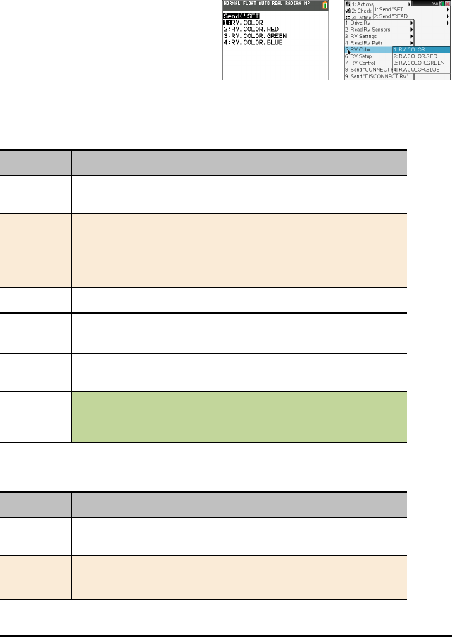
RV Color…
Send("SET Commands
RGB LED on Rover - This supports the same commands and parameters as the RGB
LED on the TI-Innovator™ Hub.
•RV Color…
– Send("SET
–RV.COLOR
–RV.COLOR.RED
–RV.COLOR.GREEN
–RV.COLOR.BLUE
RV.COLOR
Command: RV.COLOR
Command
Syntax:
RV.COLOR
Code
Sample:
Send "SET RV.COLOR
[SET] RV.COLOR rr gg bb [[BLINK] b [[TIME]
s.ss]]
Range: N/A
Describe: Set the RGB color to be displayed on the Rover's RGB LED.
Same syntax as for all RGB LED operations with COLOR, etc.
Result: Return the current RGB color, as a three-element list, that is being
displayed on the Rover's RGB LED
Type or
Addressable
Component:
Control
Note: This Rover control command is sent and executed in a queue.
RV.COLOR.RED
Command: RV.COLOR.RED
Command
Syntax:
RV.COLOR.RED
Code
Sample:
Send "SET RV.COLOR.RED
TI-Innovator™ Rover Commands version 1.2 31
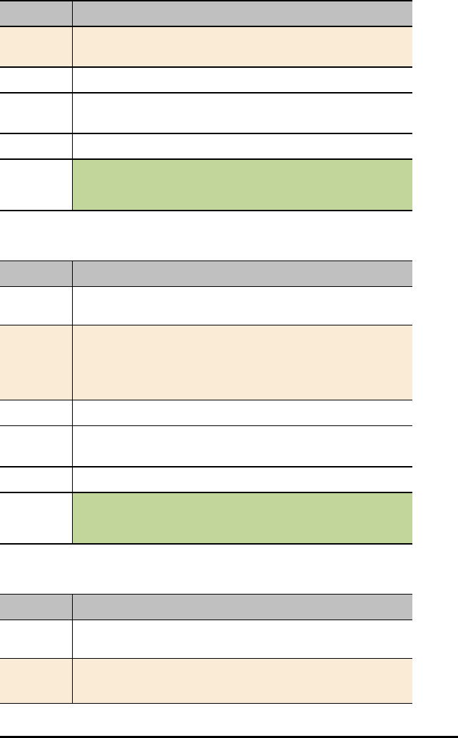
32 TI-Innovator™ Rover Commands version 1.2
Command: RV.COLOR.RED
[SET] RV.COLOR.RED rr [[BLINK] b [[TIME]
s.ss]]
Range: N/A
Describe:
Result: Set the RED color to be displayed on the Rover's RGB LED.
Type or
Addressable
Component:
Control
Note: This Rover control command is sent and executed in a queue.
RV.COLOR.GREEN
Command: RV.COLOR.GREEN
Command
Syntax:
RV.COLOR.GREEN
Code
Sample:
Send "SET RV.COLOR.GREEN
[SET] RV.COLOR.GREEN gg [[BLINK] b [[TIME]
s.ss]]
Range: N/A
Describe:
Result: Set the GREEN color to be displayed on the Rover's RGB LED.
Type or
Addressable
Component:
Control
Note: This Rover control command is sent and executed in a queue.
RV.COLOR.BLUE
Command: RV.COLOR.BLUE
Command
Syntax:
RV.COLOR.BLUE
Code
Sample:
Send "SET RV.COLOR.BLUE

Command: RV.COLOR.BLUE
[SET] RV.COLOR.BLUE bb [[BLINK] b [[TIME]
s.ss]]
Range: N/A
Describe:
Result: Set the BLUE color to be displayed on the Rover's RGB LED.
Type or
Addressable
Component:
Control
Note: This Rover control command is sent and executed in a queue.
TI-Innovator™ Rover Commands version 1.2 33
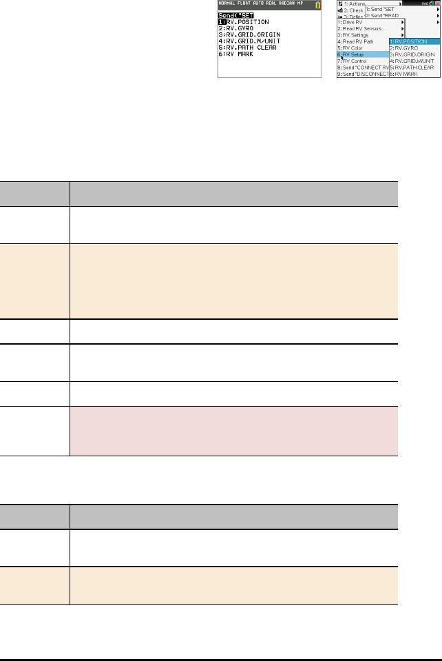
34 TI-Innovator™ Rover Commands version 1.2
RV Setup…
Send("SET Commands
•RV Setup…
– Send("SET
–RV.POSITION
–RV.GYRO
–RV.GRID.ORIGIN
–RV.GRID.M/UNIT
–RV.PATH CLEAR
–RV MARK
RV.POSITION
Command: RV.POSITION
Command
Syntax:
RV.POSITION
Code
Sample:
Send "SET RV.POSITION"
[SET] RV.POSITION xxx yyy
[hhh [[DEGREES]|RADIANS|GRADIANS]]
Range: N/A
Describe: Sets the coordinate position and optionally the heading of the Rover on
the virtual grid.
Result: Rover configuration is updated.
Type or
Addressable
Component:
Setting
RV.GYRO
Command: RV.GYRO
Command
Syntax:
RV.GYRO
Code
Sample:
Send "SET RV.GYRO"

Command: RV.GYRO
Range: N/A
Describe: Sets the on-board Gyroscope.
Result:
Type or
Addressable
Component:
Control (for Gyroscope)
RV.GRID.ORIGIN
Command: RV.GRID.ORIGIN
Command
Syntax:
RV.GRID.ORIGIN
Code
Sample:
Send "SET RV.GRID.ORIGIN"
[SET} RV.GRID.ORIGIN
Range: N/A
Describe: Sets RV as being at current grid origin point of (0,0). The "heading" is set to
0.0 resulting in the current position of the RV now set to pointing down a
virtual x-axis toward positive x values.
Result:
Type or
Addressable
Component:
Setting
RV.GRID.M/UNIT
Command: RV.GRID.M/UNIT
Command
Syntax:
RV.GRID.M/UNIT
Code
Sample:
Send "SET RV.GRID.M/UNIT"
[SET] RV.GRID.M/UNIT nnn
TI-Innovator™ Rover Commands version 1.2 35

36 TI-Innovator™ Rover Commands version 1.2
Command: RV.GRID.M/UNIT
Range: N/A
Describe: Set the size of a "grid unit" on the virtual grid. Default is 10 units per meter
(100 mm / 10 cm per unit grid). A value of 5 means 5 units per meter or
200 mm / 20 cm per unit grid). A value of 20 means 20 units per meter, or
50 mm / 5 cm per unit grid.
Result:
Type or
Addressable
Component:
Setting
RV.PATH CLEAR
Command: RV.PATH CLEAR
Command
Syntax:
RV.PATH CLEAR
Code
Sample:
Send "SET RV.PATH CLEAR"
[SET] RV.PATH CLEAR
Range: N/A
Describe: Clears any pre-existing path / waypoint information. Recommended
before doing a sequence of movement operations where waypoint / path-
list information is desired.
Result:
Type or
Addressable
Component:
Setting
RV MARK
Command: RV MARK
Command
Syntax:
RV MARK
Code
Sample:
Send "SET RV MARK"
[SET] RV MARK [[TIME] s.ss]

Command: RV MARK
Range: N/A
Describe: Enable RV to make a "mark" with a pen at the specified time interval
(default is 1 second if not specified).
A time value of 0.0 turns OFF marking.
Marking ONLY happens if the Rover is moving in a forward direction.
Result:
Type or
Addressable
Component:
Setting (for Rover)
TI-Innovator™ Rover Commands version 1.2 37
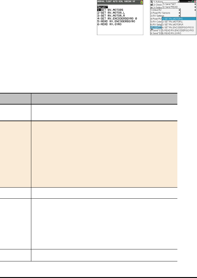
38 TI-Innovator™ Rover Commands version 1.2
RV Control…
SEND(" Commands
Wheel commands and other commands relevant for learning foundations of the Rover
vehicle.
•RV Control …
– Send("
–SET RV.MOTORS
–SET RV.MOTOR.L
–SET RV.MOTOR.R
–SET RV.ENCODERSGYRO
0
–READ
RV.ENCODERSGYRO
–READ RV.GYRO
SET RV.MOTORS
Command: SET RV.MOTORS
Command
Syntax:
SET RV.MOTORS
Code
Sample:
Send "SET RV.MOTORS"
[SET] RV.MOTORS [LEFT][CW|CCW]
<pwm value|BRAKE|COAST>
[RIGHT][CW|CCW]
<pwm value|BRAKE|COAST>
[DISTANCE ddd [M|[UNITS]|REV|FT]]
| [TIME s.ss]
Range: N/A
Describe: Set left or right or both motor PWM values. Negative values imply CCW
and Positive values imply CW. Left CW=backward motion. Left
CCW=forward motion. Right CW=forward motion, Right CCW=backward
motion. PWM values may be numeric from -255 to +255, or keywords
"COAST" or "BRAKE". Value of 0 is stop (coast).
Use of the DISTANCE option is only available if the RV is connected with all
sensors. CONNECT RV MOTORS means no sensors are available to
measure distance, so the DISTANCE option is an error in this instance.
Result: Both the LEFT and RIGHT motor, managed as a single object for direct
Command: SET RV.MOTORS
control (advanced) use.
Type or
Addressable
Component:
Control
Note: This Rover control command is sent and executed in a queue.
SET RV.MOTOR.L
Command: SET RV.MOTOR.L
Command
Syntax:
SET RV.MOTOR.L
Code
Sample:
Send "SET RV.MOTOR.L"
[SET] RV.MOTOR.L [CW|CCW] <+/-pwm
value|BRAKE|COAST>
[TIME s.ss] | [DISTANCE ddd [[UNITS]
|M|REV|FT]]
Range: N/A
Describe: Set left motor direct PWM value. CCW = forward, CW = backward, pwm
value negative = forward, positive = backward. TIME option available in all
modes, DISTANCE option available only when RV is fully connected (not
the RV MOTORS option).
Result: Left wheel motor and control for direct control (advanced) use.
Type or
Addressable
Component:
Control
Note: This Rover control command is sent and executed in a queue.
SET RV.MOTOR.R
Command: SET RV.MOTOR.R
Command
Syntax:
SET RV.MOTOR.R
Code
Sample:
Send "SET RV.MOTOR.R"
[SET] RV.MOTOR.R [CW|CCW] <+/-pwm
value|BRAKE|COAST>
[TIME s.ss] | [DISTANCE ddd [[UNITS]
|M|REV|FT]]
TI-Innovator™ Rover Commands version 1.2 39

40 TI-Innovator™ Rover Commands version 1.2
Command: SET RV.MOTOR.R
Range: N/A
Describe: Set right motor direct PWM value. CW = forward, CCW = backward, pwm
value positive = forward, negative = backward. TIME option available in all
modes, DISTANCE option available only when RV is fully connected (not
the RV MOTORS option).
Result: Right wheel motor and control for direct control (advanced) use.
Type or
Addressable
Component:
Control
Note: This Rover control command is sent and executed in a queue.
SET RV.ENCODERSGYRO 0
Command: SET RV.ENCODERSGYRO 0
Command
Syntax:
SET RV.ENCODERSGYRO 0
Code
Sample:
Send "SET RV.ENCODERSGYRO 0"
Range: N/A
Describe: Reset the left and right encoder, coupled with the gyro and operating time
information.
Result:
Type or
Addressable
Component:
Control
Note: This Rover control command is sent and executed in a queue.
READ RV.ENCODERSGYRO
Command: READ RV.ENCODERSGYRO
Command
Syntax:
READ RV.ENCODERSGYRO
Code
Sample:
Send "READ RV.ENCODERSGYRO"
Range: N/A

Command: READ RV.ENCODERSGYRO
Describe: The left and right encoder, coupled with the gyro and operating time
information.
Result: List of values of current left and right encoder, coupled with gyro and
operating time information
Type or
Addressable
Component:
Control
Note: This Rover READ command is executed immediately.
READ RV.GYRO
Command: READ RV.GYRO
Command
Syntax:
READ RV.GYRO
Code
Sample:
Send "READ RV.GYRO"
READ RV.GYRO [[DEGREES]|RADIANS|GRADIANS]
Range: N/A
Describe: The gyroscope is used to maintain the heading of Rover while it’s in
motion. It can also be used to measure the change in angle during turns.
The gyroscope is ready to use after the CONNECT RV command is
processed.
The GYRO object shall be usable even when the RV is not in motion.
Result: Returns current gyro sensor angular deviation from 0.0, reading partially
drift-offset compensated.
Type or
Addressable
Component:
Control
Note: This Rover READ command is executed immediately.
TI-Innovator™ Rover Commands version 1.2 41
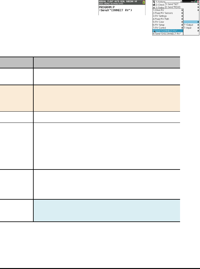
42 TI-Innovator™ Rover Commands version 1.2
Send "CONNECT RV"
SEND("CONNECT RV") Commands
CONNECT RV - initializes the hardware connections.
• Connects RV and inputs and outputs built into the RV.
• Resets the Path and the Grid Origin.
• Sets the units per meter to default value.
•Send("CONNECT RV")
CONNECT RV
Command: CONNECT RV
Command
Syntax:
CONNECT RV [MOTORS]
Code
Sample:
Send "CONNECT RV"
Send "CONNECT RV MOTORS"
Range: N/A
Describe: The "CONNECT RV" command configures the TI-Innovator™ Hub
software to work with the TI-Innovator™ Rover.
It establishes the connections to the various devices on the Rover – two
motors, two encoders, one gyroscope, one RGB LED and one
color sensor. It also clears the various counters and sensor values. The
optional ‘MOTORS’ parameter configures only the motors and allows
direct control of motors without the additional peripherals.
Result: Connects the Rover Vehicle to the TI-Innovator™ Hub.
This establishes connections with the motor driver, color sensor,
gyroscope, ultrasonic ranger, and RGB LED.
The Rover is now ready to be programmed
Type or
Addressable
Component:
All components of the Rover - two motors, two encoders, one
gyroscope, one RGB LED and one color sensor.
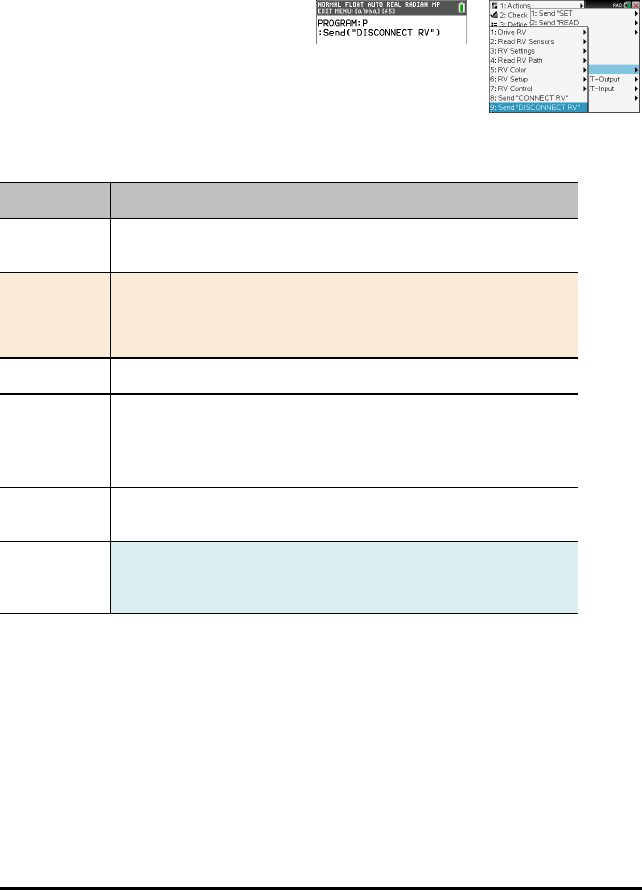
Send "DISCONNECT RV"
SEND("DISCONNECT RV") Commands
DISCONNECT RV - disconnects all the hardware peripherals from the Hub.
Format: Send("DISCONNECT RV")
•Send("DISCONNECT RV")
DISCONNECT RV
Command: DISCONNECT RV
Command
Syntax:
DISCONNECT RV
Code
Sample:
Send "DISCONNECT RV"
DISCONNECT RV
Range: N/A
Describe: The "DISCONNECT RV" command removes the logical connections
between the TI-Innovator™ Hub and the TI-Innovator™ Rover.
It also clears the counters and sensor values. It allows the use of the
breadboard port of the TI-Innovator™ Hub with other devices.
Result: The TI-Innovator™ Hub is now logically disconnected from the TI-
Innovator™ Rover
Type or
Addressable
Component:
N/A
TI-Innovator™ Rover Commands version 1.2 43

44 TI-Innovator™ Rover – Programmable Component Data Sheets
TI-Innovator™ Rover – Programmable Component Data
Sheets
The TI-Innovator™ Rover Programmable Component Data Sheets include the following;
a product name or number, a brief description, a product image, specifications, how
the component connects to the TI-Innovator™ Hub, and Rover commands with simple
code samples.
Device
Device Category
Rover (RV) Accessory
Sensors
Sensors Category
Rotary Encoders Motion and Distance Sensor
Gyroscope Motion and Distance Sensor
Ultrasonic Ranger Motion and Distance Sensor
Color Sensor Environmental Sensor
On-Board Light Brightness Sensor (On
Hub)
Environmental Sensor
Controllable Devices
Controllable Devices Category
Electric Motors Motors
RGB (Red-Green-Blue) LED LEDs and Displays
On-Board Speaker (on Hub) Sound Output
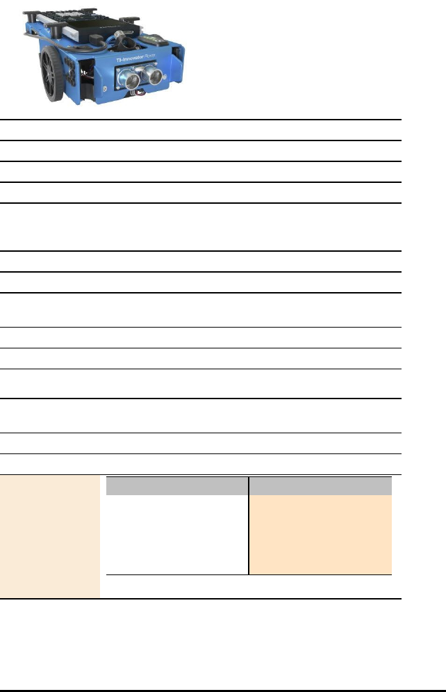
TI-Innovator™ Rover
Title TI-Innovator™ Rover Data Sheet
TI Item Name TI-Innovator™ Rover
Quantity 1
Included in TI-Innovator™ Rover
Description TI-Innovator™ Rover is a two-wheeled programmable
robotic vehicle which works with the TI-Innovator™ Hub
with TI LaunchPad™ Board.
Category Accessory
Hub Connection See: Connecting TI-Innovator™ Rover
Assembly
Instructions
See: Exploring the Assembled TI-Innovator™ Rover
Precautions See: General Precautions
Specifications See: TI-Innovator™ Rover Setup Requirements
Rover
Commands
Sketch Object RV
Command Syntax
Code
Sample: Desired Action Code Sample
Configure Hub for
additional commands such
as:
RV Forward 2
RV Left
Send "CONNECT RV"
TI-Innovator™ Rover – Programmable Component Data Sheets 45
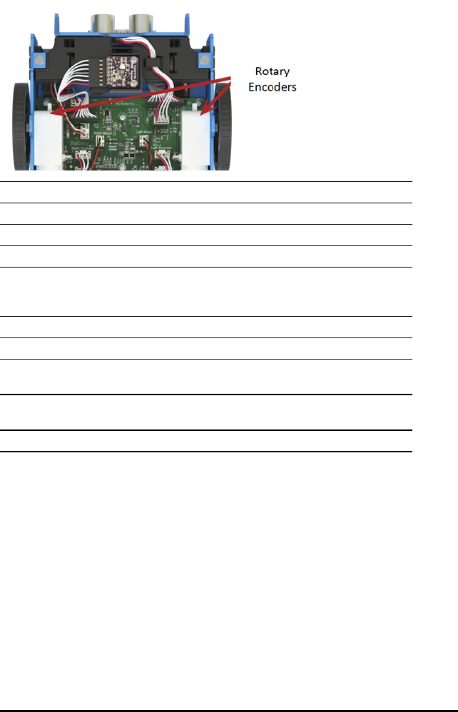
46 TI-Innovator™ Rover – Programmable Component Data Sheets
TI-Innovator™ Rover On-Board Rotary Encoders Data Sheet
Title TI-Innovator™ Rover Rotary Encoders
TI Item Name Built into the TI-Innovator™ Rover
Quantity 2 - 1 for each wheel
Included in TI-Innovator™ Rover
Description Calculates linear distance by detecting how many
rotations the wheels make as the Rover moves. Assists in
balancing and aligning the wheels.
Category Motion and Distance Sensors
Hub Connection on-board Rover
Assembly
Instructions
Not Applicable
Precautions Do not unscrew the case enclosure. Encoder has sharp
edges that should not be exposed.
Specifications Not Applicable
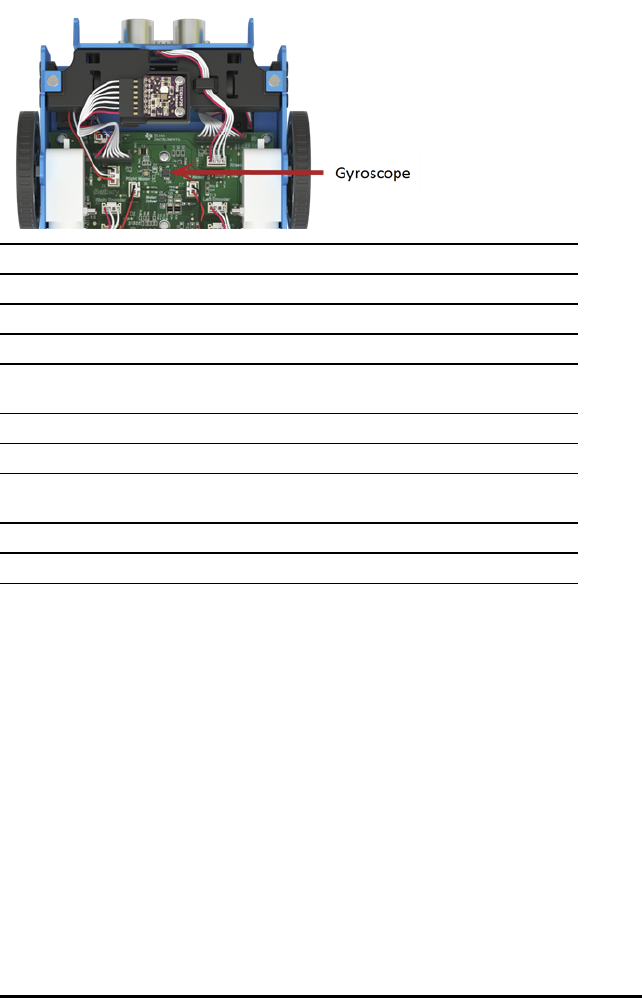
TI-Innovator™ Rover On-Board Gyroscope Data Sheet
Title TI-Innovator™ Rover Gyroscope
TI Item Name Built into the TI-Innovator™ Rover
Quantity 1
Included in TI-Innovator™ Rover
Description Calculates angular displacement and heading as it
maintains orientation.
Category Motion and Distance Sensors
Hub Connection on-board Rover
Assembly
Instructions
Not Applicable
Precautions Not Applicable
Specifications Not Applicable
TI-Innovator™ Rover – Programmable Component Data Sheets 47
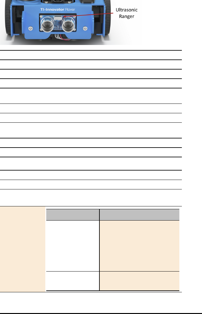
48 TI-Innovator™ Rover – Programmable Component Data Sheets
TI-Innovator™ Rover On-Board Ultrasonic Ranger Data Sheet
Title Ultrasonic Ranger
TI Item Name Built into the Rover
Quantity 1
Included in TI-Innovator™Rover
Description Non-contact measurement module that reads distance from
obstacle in meters.
Category Motion and Distance Sensors
Hub Connection On-board the Rover
Assembly
Instructions
Not Applicable
Precautions
Specifications Measures distances up to 4 m
Rover Commands
Sketch Object RV.RANGER
Command Syntax Send("READ RV.RANGER")
Code
Sample: Desired Action Code Sample
Connects the Rover to
the TI-Innovator Hub.
This establishes
connections with the
motor driver, color
sensor, gyroscope,
ultrasonic ranger, and
proximity sensors.
CONNECT RV
Returns the current
distance from the front
READ RV.RANGER
Get (R)

Rover Commands
Desired Action Code Sample
of the Rover to an
obstacle. If there is no
obstacle detected, a
range of 10.00 meters
is reported
TI-Innovator™ Rover – Programmable Component Data Sheets 49
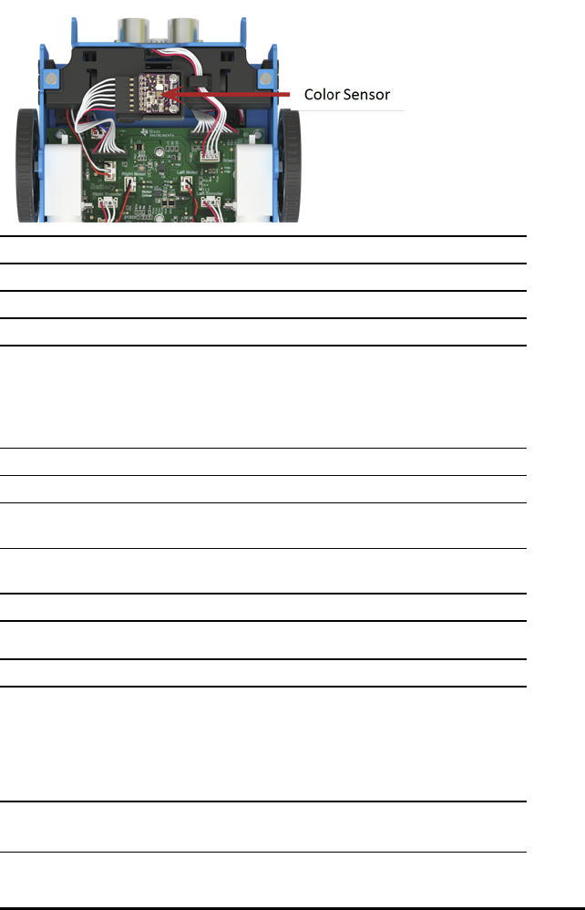
50 TI-Innovator™ Rover – Programmable Component Data Sheets
TI-Innovator™ Rover On-Board Color Sensor Data Sheet
Title TI-Innovator™ Rover Color Sensor
TI Item Name Built into the TI-Innovator™ Rover
Quantity 1
Included in TI-Innovator™ Rover
Description Bottom-mounted color sensor detects the color of the
surface. Can also detect gray-level scale of black (0) to
white (255).
Measures surface color. Used to identify colors and
execute Rover Hub commands based on color.
Category Environmental Sensors
Hub Connection on-board Rover
Assembly
Instructions
Not Applicable
Precautions Do not unplug the cable. If it becomes unattached see
proper positioning as shown above.
Specifications Not Applicable
Rover Commands
Sketch Object RV.COLORINPUT
RV.COLORINPUT.RED
RV.COLORINPUT.GREEN
RV.COLORINPUT.BLUE
RV.COLORINPUT.GRAY
Command Syntax

Rover Commands
Code
Sample: Desired Action Code Sample
Send "READ
RV.COLORINPUT.RED"
Get (C)
TI-Innovator™ Rover – Programmable Component Data Sheets 51

52 TI-Innovator™ Rover – Programmable Component Data Sheets
On-Board Light Brightness Sensor Data Sheet
Title On-Board Light Brightness Sensor
TI Item Name Built into the Hub
Quantity 1
Included in TI-Innovator™ Hub
Description Built-in light brightness sensor located at the bottom of the
Hub. The sensor detects light intensity.
Category Environmental Sensors
Hub Connection on-board Hub
Assembly
Instructions
Not Applicable
Precautions Not Applicable
Specifications Not Applicable
HUB Commands
Sketch Object BRIGHTNESS
Command Syntax Send("READ BRIGHTNESS")
Code
Sample: Desired Action Code Sample
Read the built-in
light brightness
sensor
Send("READ
BRIGHTNESS")
Get(B)
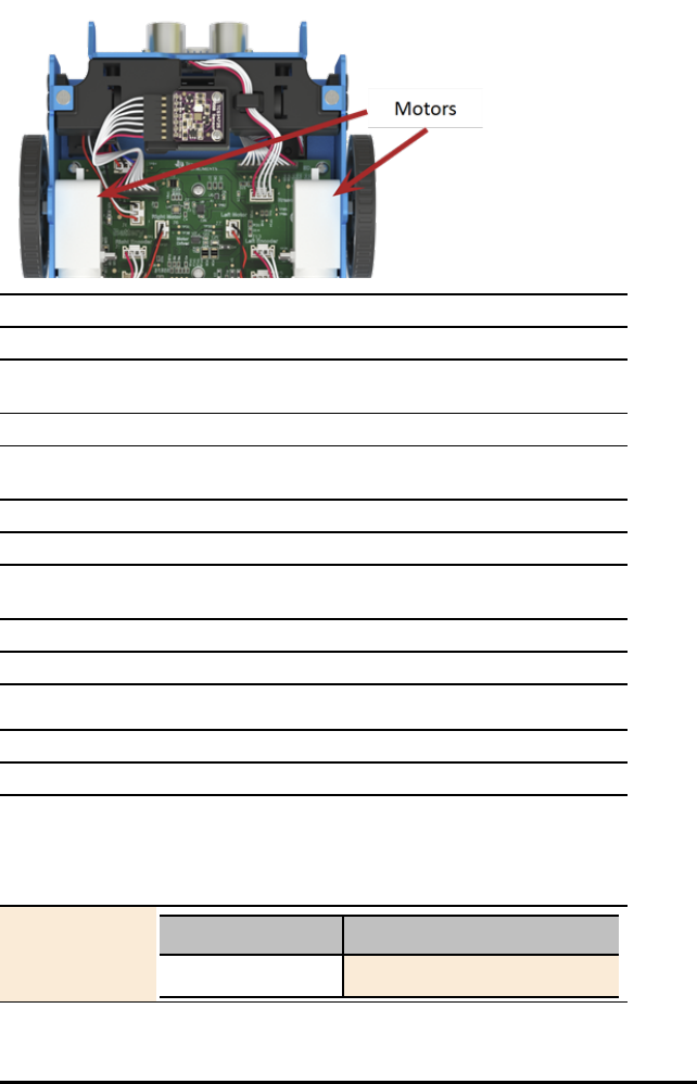
TI-Innovator™ Rover On-Board Electric Motors Data Sheet
Title TI-Innovator™ Rover Motors
TI Item Name Built into the TI-Innovator™ Rover
Quantity 2 – 1 on each wheel with electric motor and rotary
encoder to track rotations.
Included in TI-Innovator™ Rover
Description Motors that can be programmed to move the wheels
independently and at variable speeds.
Category Motors
Hub Connection on-board Rover
Assembly
Instructions
Not Applicable
Precautions Not Applicable
Specifications Not Applicable
Rover Commands Send "SET RV.MOTORS
Sketch Object RV.MOTORS
Command Syntax
Code
Sample: Desired Action Code Sample
Direct control of Send "SET RV.MOTORS"
TI-Innovator™ Rover – Programmable Component Data Sheets 53

54 TI-Innovator™ Rover – Programmable Component Data Sheets
Rover Commands Send "SET RV.MOTORS
Desired Action Code Sample
motors.
[SET] RV.MOTORS [LEFT]
[CW|CCW]
<pwm
value|BRAKE|COAST>
[RIGHT][CW|CCW]
<pwm
value|BRAKE|COAST>
[DISTANCE ddd
[M|[UNITS]|REV|FT]]
| [TIME s.ss]
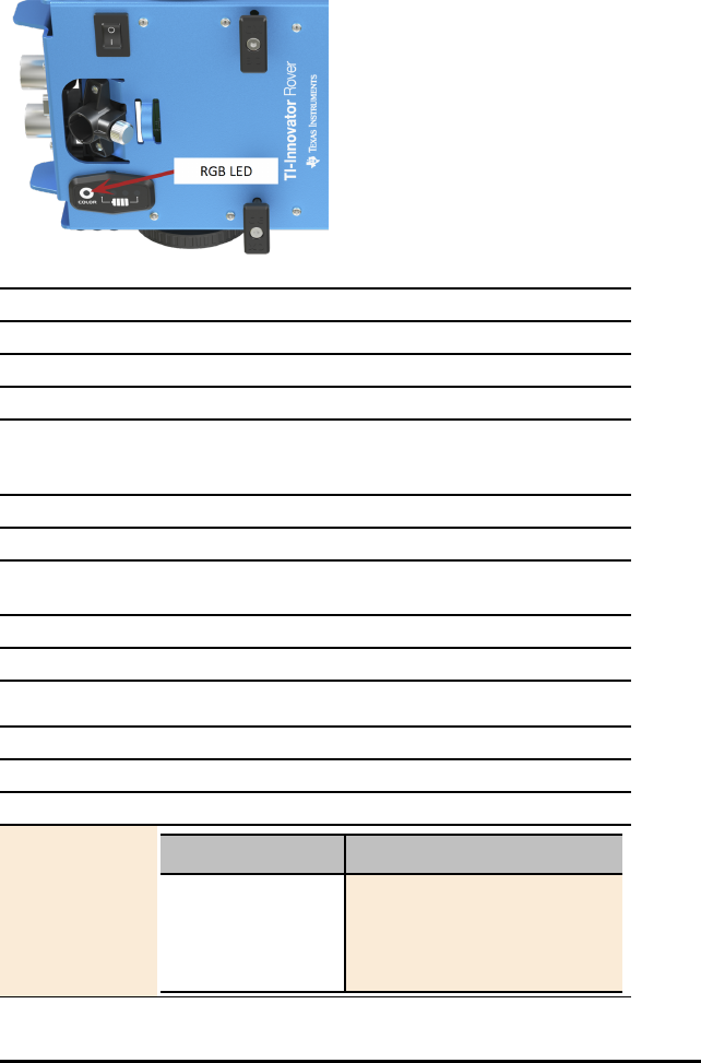
TI-Innovator™ Rover On-Board RGB (Red-Green-Blue) LED Data
Sheet
Title TI-Innovator™ Rover RGB (Red-Green-Blue) LED
TI Item Name Built into the TI-Innovator™ Rover
Quantity 1
Included in TI-Innovator™ Rover
Description Light-emitting diode with independently adjustable red,
green and blue elements. Can produce a wide variety of
colors.
Category LEDs and Displays
Hub Connection on-board Rover
Assembly
Instructions
Not Applicable
Precautions Not Applicable
Specifications Not Applicable
Rover Commands
Sketch Object RV.COLOR
Command Syntax
Code
Sample: Desired Action Code Sample
Configure LED
Note:
RV.COLOR supports
the same functions
Send("SET RV.COLOR 255
0 255")
TI-Innovator™ Rover – Programmable Component Data Sheets 55

56 TI-Innovator™ Rover – Programmable Component Data Sheets
Rover Commands
Desired Action Code Sample
as the Hub COLOR
object
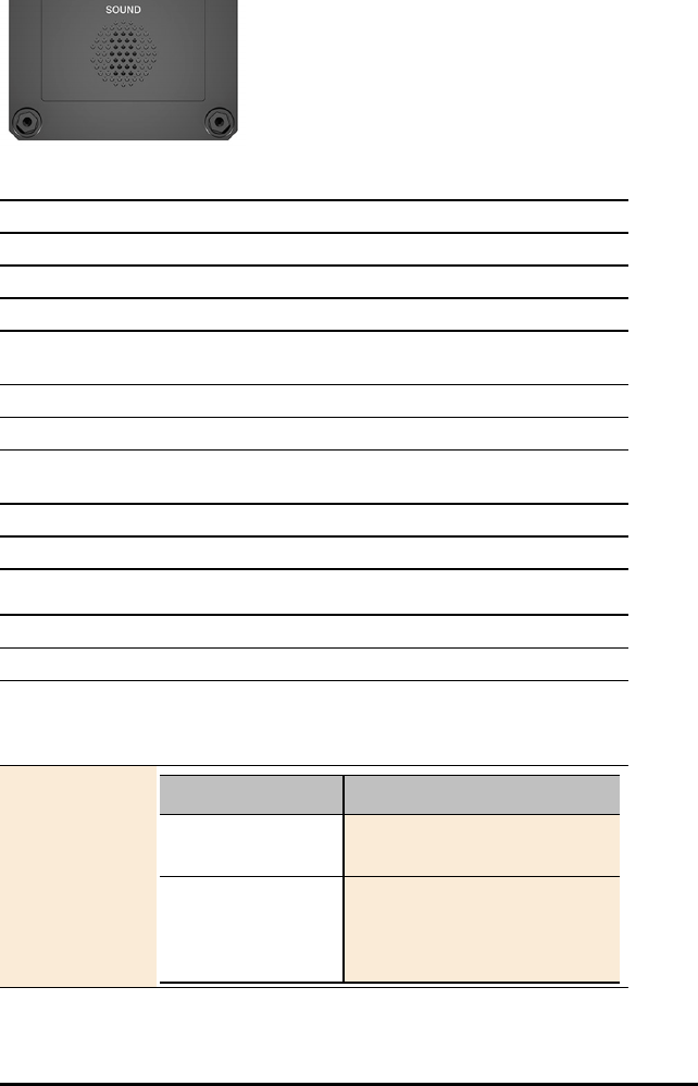
On-Board Speaker Data Sheet
Speaker (at back of Hub) is addressable as "SOUND" in Hub command strings.
Title On-Board Speaker
TI Item Name Built into the Hub
Quantity 1
Included in TI-Innovator™ Hub
Description Built-in speaker located at the back of the Hub. It converts
electrical current into sound you can hear.
Category Sound Output
Hub Connection on-board Hub
Assembly
Instructions
Not Applicable
Precautions Not Applicable
Specifications Not Applicable
HUB Commands
Sketch Object SOUND
Command Syntax Send("SET SOUND …")
Frequency in Hz or Note as C1, CS1, D2, ...
[TIME duration in seconds]
Code
Sample: Desired Action Code Sample
Play tone at 261.23
Hz
Send("SET SOUND
261.23")
Evaluate the
expression 2^8 (=
256) and play that
tone
Send("SET SOUND eval
(2^8)")
TI-Innovator™ Rover – Programmable Component Data Sheets 57

58 TI-Innovator™ Rover – Programmable Component Data Sheets
HUB Commands
Desired Action Code Sample
Evaluate the
expression 2^8 (=
256) and play that
tone for .25 seconds
Send("SET SOUND eval
(2^8) TIME .25")
Evaluate the
expression 2^9 (=
512) and play that
tone for 0.25
seconds (result of
evaluating 1/4)
Send("SET SOUND eval
(2^9) TIME eval(1/4)")
Turn speaker off Send("SET SOUND OFF")

I/O Modules Data Sheets
The TI-Innovator™ I/O Module Data Sheets include the following; a product name and
number, a brief description, a product image, specifications, how the component
connects to the TI-Innovator™ Hub, and Hub commands with simple code samples.
Topic Links
•Analog Light Sensor Data Sheet
•Vibration Motor Data Sheet
•White LED Data Sheet
•Servo Motor Data Sheet
•Ultrasonic Ranger Data Sheet
I/O Modules Data Sheets 59
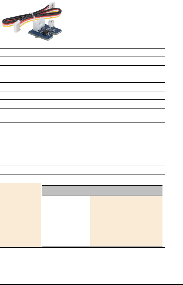
60 I/O Modules Data Sheets
Analog Light Sensor Data Sheet
Title Analog Light Sensor
TI Item Name STEMKT/AC/A
Quantity 1
Included in TI-Innovator™I/O Module Pack
Description Sensor that detects the light intensity of the environment.
Category Environmental Sensors
Hub Connection 4-Pin Cable to any of these ports: IN 1, IN 2, IN 3
Assembly
Instructions
Not applicable
Precautions Light sensor leads may break if bent repeatedly
Specifications Maximum voltage: 150, Maximum power: 100,
Environmental Temp: -30~+70, Spectrum Peak Value: 540
HUB Commands
Sketch Object LIGHTLEVEL
Command Syntax Send("READ LIGHTLEVEL n")
Code
Sample: Desired Action Code Sample
Configure the
program to use
LIGHTLEVEL on port
IN 1
Send("CONNECT
LIGHTLEVEL 1 TO IN 1")
Read the light
sensor
Send("READ LIGHTLEVEL
1")
Get(L)
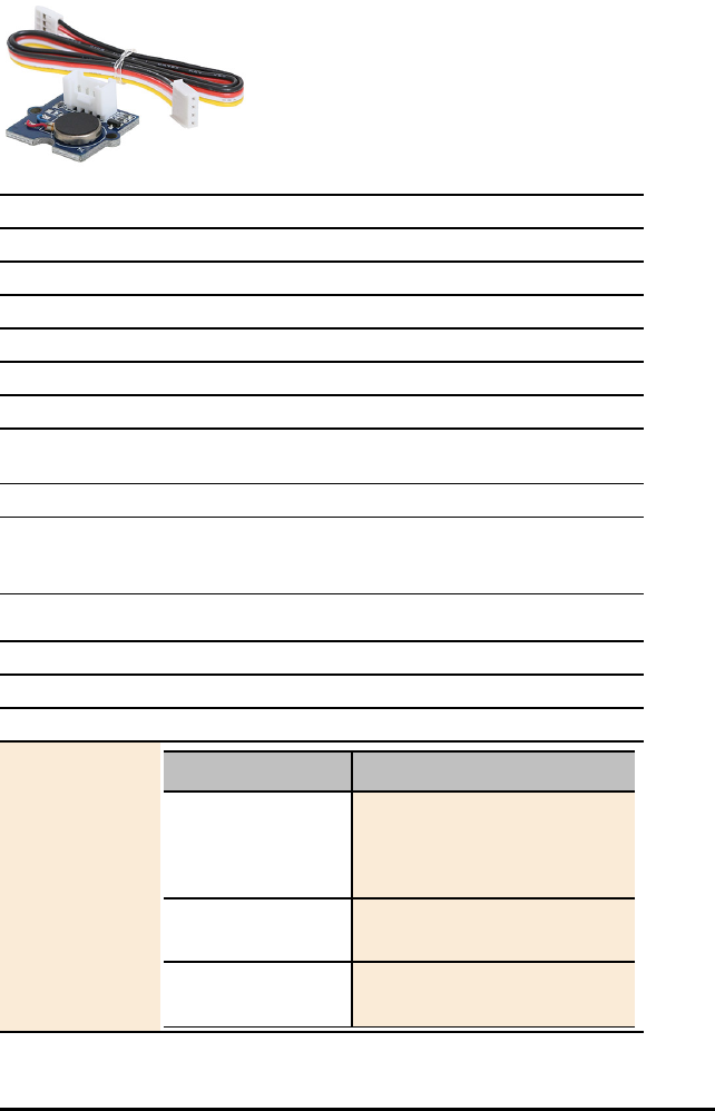
Vibration Motor Data Sheet
Title Vibration Motor
TI Item Name STEMKT/AC/B
Quantity 1
Included in TI-Innovator™I/O Module Pack
Description Coin type motor that vibrates when the input logic is HIGH.
Category Motors
Hub Connection 4-Pin Cable to any of these ports: OUT 1, OUT 2, OUT 3
Assembly
Instructions
Not Applicable
Precautions Use an Auxiliary Power Source
Specifications Operate Voltage: 3.0V to 5.5V, Control Mode: Logic Level
(When Logic HIGH, the motor is ON. When LOW, the motor
is OFF.), Rated speed: 9000 rpm
HUB Commands
Sketch Object VIB.MOTOR
Command Syntax Send("SET VIB.MOTOR 1 TO pwm") - pwm from 0 to 255
Code
Sample: Desired Action Code Sample
Configure the
program to use
ANALOG.OUT on
port OUT 1
Send("CONNECT
VIB.MOTOR 1 TO OUT 1")
Turn OFF vibration
motor
Send("SET VIB.MOTOR 1
TO 0")
Turn ON vibration
motor at full power
Send("SET VIB.MOTOR 1
TO 255")
I/O Modules Data Sheets 61

62 I/O Modules Data Sheets
HUB Commands
Desired Action Code Sample
Turn ON vibration
motor at half power
Send("SET VIB.MOTOR 1
TO 128")
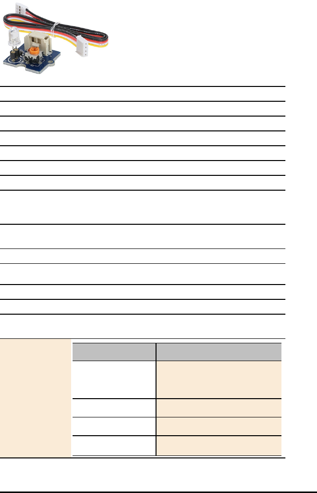
White LED Data Sheet
Title White LED
TI Item Name STEMKT/AC/C
Quantity 1
Included in TI-Innovator™I/O Module Pack
Description White LED module that bends to any position.
Category LEDs and Displays
Hub Connection 4-Pin Cable to any of these ports: OUT 1, OUT 2, OUT 3
Assembly
Instructions
Insert LED into socket - longer leg (lead) is positive (anode).
If both leads are of equal length, the lead adjacent to the
flat edge on LED casing is the negative (cathode) lead.
Precautions Do not bend the leads repeatedly; this will weaken the
wires and may cause them to break.
Specifications Operating voltage: 3.3v/5v, Emitting Color: White
HUB Commands
Sketch Object LED
Command Syntax Send("SET LED 1 TO ON/OFF [[BLINK|TOGGLE] frequency]
[[TIME] seconds]")
Code
Sample: Desired Action Code Sample
Configure the
program to use LED
on port OUT 1
Send("CONNECT LED 1 TO
OUT 1")
Turn LED ON Send("SET LED 1 ON")
Turn LED OFF Send("SET LED 1 OFF")
Turn external LED Send("SET LED 1 TO ON
I/O Modules Data Sheets 63

64 I/O Modules Data Sheets
HUB Commands
Desired Action Code Sample
ON for 5 seconds TIME 5")
Turn external LED
ON and blink it at 2
Hz (2 times a
second) for 5
seconds
Send("SET LED 1 TO ON
BLINK 2 TIME 5")

Servo Motor Data Sheet
There are two types of Servo motors, continuous and sweep. More about SERVO Motors
Title Servo Motor
TI Item Name STEMKT/AC/D
Quantity 1
Included in TI-Innovator™I/O Module Pack
Description 360 degree, continuous rotation servo motor with gearing
and feedback system; used in driving mechanism of robots.
Category Motors
Hub Connection 4-Pin Cable to only this port: OUT 3
Assembly
Instructions
Mount a gear to the top of the Servo Motor using one of
the provided screws.
Precautions Use an Auxiliary Power Source. Do not hold the Servo
Motor’s shaft while it is rotating. Also, do not rotate the
Servo Motor by hand.
Specifications Operating Speed: 110RPM (4.8V), 130RPM (6V); Stall
Torque: 1.3kg.cm/18.09oz.in (4.8V), 1.5kg.cm/20.86oz.in
(6V); Operating Voltage: 4.8V~6V
HUB Commands
Sketch Object SERVO
Command Syntax Send("SET SERVO n TO [CW/CCW] speed [[TIME] seconds] --
speed from -100 to 100, CW/CCW
(Clockwise/Counterclosewise) optional, if speed <0, CCW,
else CW unless CW/CCW keyword is specified,
TIME optional, in seconds, default=1 second (for
continuous servo operation)
(CW/CCW required if TIME/seconds NOT specified.)
I/O Modules Data Sheets 65

66 I/O Modules Data Sheets
HUB Commands
Code
Samples: Desired Action for
the
SERVO.CONTINOUS
Code Sample
Configure the
program to use
SERVO on port OUT
3
Send("CONNECT SERVO 1
TO OUT 3")
Set SERVO to turn
Counterclockwise
(CCW) at full (100%)
speed for 2 seconds
Send("SET SERVO 1 CCW
100 2")
Set SERVO to turn
Clockwise (CW) at
half (50%) speed for
1 second (default
time if not
specified)
Send("SET SERVO 1 CW
50")
Turn SERVO Off Send("SET SERVO 1
ZERO")
or
Send("SET SERVO 1
STOP")
More about SERVO Motors
There are two types of Servo motors, continuous and sweep.
• The motor in the I/O pack is a continuous motor. This motor rotates either clockwise
(positive direction) or counter clockwise (negative direction) for a specified amount of
time.
• Sweep servo motors turn only 90 degrees in each direction.
It is necessary to connect servo motors to the OUT 3 port. This port provides the 5 volts
needed for these motors.
• You will also need to plug an external battery into the PWR micro USB port.
• You will also give a number, in this case 1, as part of identifying to an external device
plugged into a port. (Note: In some cases you may have multiple devices of the same
type connected to the TI-Innovator (e.g. temperature probes))
Code
Sample:
Send("CONNECT SERVO.CONTINUOUS 1 TO OUT 3
")
The first argument sets the speed and direction of the motor. You can use -100 to 100.
Negative values are in the counter clockwise direction. Positive values are in the clockwise
direction. Zero stops the motor.
The second argument is the amount of time in seconds to run the motor in the specified
direction and speed. If there is no argument for time, then the motor will turn for one
second.
The Wait command is used in the case to delay execution of commands on the calculator
until the motor action is complete. This optional command is useful in delaying commands
that might replace the current motor command before the desired end time.
Code
Sample:
Send("SET SERVO.CONTINUOUS 1 ¬50 TIME 2")
Wait 2
You also have the options of using explicit CW and CCW settings with values for speed of 0
to 100.
Code
Sample:
Send("SET SERVO.CONTINUOUS 1 CW 100 TIME
3")
Wait 3
This example prompts for the inputs to the SERVO.CONTINUOUS command.
The example also uses a While loop with getKey as a way for the user to control when the
command to stop the motor is executed.
Code
Sample:
ClrHome
Disp "S:SPEED AND DIRECTION"
Disp "ENTER VALUES ¬100 TO 100 FOR S"
Disp "T:TIME IN SECONDS"
Prompt S,T
Send("SET SERVO.CONTINUOUS 1 eval(S) TIME
eval(T)")
Disp "PRESS 1 TO STOP THE MOTOR AND END THE
PROGRAM"
0→K
While K≠92
getKey→K
End
Send("SET SERVO.CONTINUOUS 1 0”)
I/O Modules Data Sheets 67
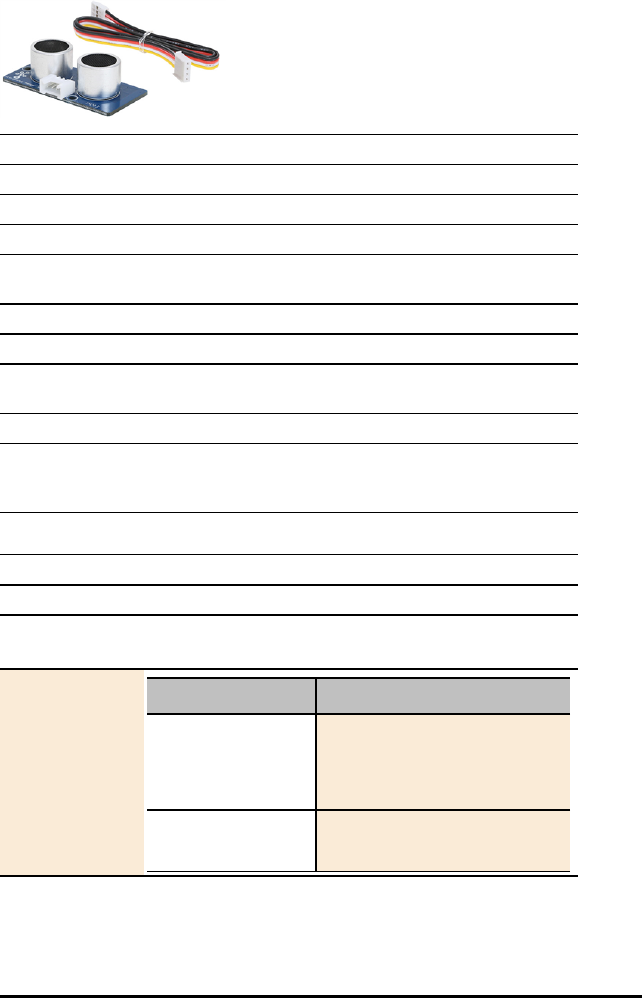
68 I/O Modules Data Sheets
Ultrasonic Ranger Data Sheet
Title Ultrasonic Ranger
TI Item Name STEMKT/AC/E
Quantity 1
Included in TI-Innovator™Ultrasonic Ranger Module
Description Non-contact measurement module that reads distance from
sensor in meters.
Category Motion and Distance Sensors
Hub Connection 4-Pin Cable to any of these ports: IN 1, IN 2
Assembly
Instructions
Not Applicable
Precautions Sold separately, not included in the I/O Modules Pack
Specifications Operating voltage: 3.3~5V, Operating current: 15mA,
Ultrasonic frequency: 42kHz, Measuring range: 3-400m,
Resolution: 1m, Output: PWM
HUB Commands
Sketch Object RANGER
Command Syntax Send("READ RANGER n")
Get(R)
Code
Sample: Desired Action Code Sample
Configure the
program to use
RANGER on port IN
1
Send("CONNECT RANGER 1
TO IN 1")
Read the Ultrasonic
Ranger
Send("READ RANGER 1")
Get(R)

TI-Innovator™ Breadboard Data Sheets
The TI-Innovator™ Breadboard Data Sheets include the following; a product name and
number, a brief description, a product image, specifications, how the component
connects to the TI-Innovator™ Hub, and simple code samples.
Topic Links
•Breadboard Components and Usable Pins
•Environmental Sensors
•LEDs and Displays
•Motors
•Power and Signal Control
•Passive Components
TI-Innovator™ Breadboard Data Sheets 69

70 TI-Innovator™ Breadboard Data Sheets
Breadboard Components and Usable Pins
Here is a list of all the components in our breadboard pack and the usable pins for each
component.
Component Use with pins
1 Breadboard N/A
10 Male/Female Breadboard Jumper Cables N/A
40 Male/Male Breadboard Jumper Cables N/A
5 Green LED BB 1-10
10 Red LED BB 1-10
2 RGB (Red-Green-Blue) LED BB 8-10
10 Resistor 100 Ohm N/A
10 Resistor 1K Ohm N/A
10 Resistor 10K Ohm N/A
10 Resistor 100K Ohm N/A
10 Resistor 10M Ohm N/A
1 Diode BB 1-10
1 Thermistor BB 5,6,7 (analog input required)
1 SPDT Slide Switch BB 1-10
1 8 Position SIP DIP Switch BB 1-10 (digital input)
1 8 100 Ohm Resistor SIP N/A
1 Potentiometer with Knob BB 5,6,7
1 Capacitor 100µF N/A
1 Capacitor 10µF N/A
1 Capacitor 1µF N/A
1 7-Segment Display BB 1-10
1 Small DC Motor BB 1-10 (uses digital to generate software
PWM)
2 TTL Power MOSFET BB 1-10
1 TI Analog Temperature Sensor BB 5,6,7 (analog input required)
1 Visible Light Sensor BB 5,6,7 (analog input required)
1 4-AA Battery Holder N/A
1 Infrared Receiver BB 1-10 (digital input)
1 Infrared Transmitter BB 1-10 (digital output)


72 TI-Innovator™ Breadboard Data Sheets
Thermistor Data Sheet
Title Thermistor
TI Item Name STEMEE/AC/THERM/A
Quantity 1
Included in TI-Innovator™ Breadboard Pack
Description Resistor whose resistance changes based on temperature.
Used for measurement and control.
Category Environmental Sensors
Hub Connection breadboard circuit
Assembly
Instructions
No polarity
Precautions Not Applicable
Specifications Resistance in Ohms @ 25°C: 10k, Resistance Tolerance:
±1%, B Value Tolerance: ±1%, Operating Temperature: -
40°C ~ 125°C, Power – Max: 7.5mW
HUB Commands
Sketch Object THERMISTOR
Command Syntax Send("READ THERMISTOR n")
Code
Sample: Desired Action Code Sample
Configure the
program to use
THERMISTOR on pin
BB 1
Send("CONNECT
THERMISTOR 1 TO BB 1")
Read the thermistor Send("READ THERMISTOR
1")
Get(T):Disp T
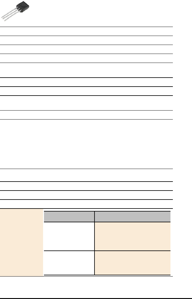
TI Analog Temperature Sensor Data Sheet
Title TI Analog Temperature Sensor
TI Item Name STEMEE/AC/TEMPSN/A
Quantity 1
Included in TI-Innovator™ Breadboard Pack
Description Sensor that reports a voltage proportional to the ambient
temperature within a range of −55°C to 130°C.
Category Environmental Sensors
Hub Connection breadboard circuit
Assembly
Instructions
Not Applicable
Precautions Not Applicable
Specifications Accuracy at +30°C ±2.5 °C (max)’
Accuracy at +130°C & −55°C ±3.5 to ±3.8 °C (max)’
Power Supply Voltage Range +2.4V to +5.5V’
Current Drain 10 μA (max), Nonlinearity ±0.4 % (typ),
Output Impedance 160 Ω (max), Load Regulation0µA < IL<
+16 µA
See:Detailed Technical documentation.
HUB Commands
Sketch Object TEMPERATURE
Command Syntax Send("READ TEMPERATURE n")
Code
Sample: Desired Action Code Sample
Configure the
program to use
TEMPERATURE on
pin BB 1
Send("CONNECT
TEMPERATURE 1 TO BB
1")
Read the
temperature sensor
Send("READ TEMPERATURE
1")
Get (T):Disp T
TI-Innovator™ Breadboard Data Sheets 73

74 TI-Innovator™ Breadboard Data Sheets
Visible Light Sensor Data Sheet
Title Visible Light Sensor
TI Item Name STEMEE/AC/LHTSEN/A
Quantity 1
Included in TI-Innovator™ Breadboard Pack
Description Sensor that reports the level of ambient light.
Category Environmental Sensors
Hub Connection breadboard circuit
Assembly
Instructions
Not Applicable
Precautions Not Applicable
Specifications
HUB Commands
Sketch Object LIGHTLEVEL or ANALOG.IN
Command Syntax Send("READ LIGHTLEVEL n")
Code
Sample: Desired Action Code Sample
Configure the
program to use
LIGHT LEVEL on pin
BB 4
Send("CONNECT
LIGHTLEVEL 1 TO BB 4")
Read the light
sensor
Send("READ LIGHTLEVEL
1")
Get(L):Disp L


76 TI-Innovator™ Breadboard Data Sheets
Green LED Data Sheet
Title Green LED
TI Item Name STEMEE/AC/LED/A
Quantity 5
Included in TI-Innovator™ Breadboard Pack
Description Light-emitting diode that emits green light when current
passes through it.
Category LEDs and Displays
Hub Connection breadboard circuit
Assembly
Instructions
Longer leg (lead) is positive (anode). If both leads are of
equal length, the lead adjacent to the flat edge on LED
casing is the negative (cathode) lead.
Precautions Do not insert the leads of LEDs directly into the Hub’s
Breadboard Connector. Assemble the components on the
breadboard and use the provided jumper cables to connect
the breadboard to the Hub.
Specifications Voltage - Forward (Vf) (Typ): 2.1V, Current – Test: 10mA,
Viewing Angle: 36°, Mounting Type: Through Hole.
HUB Commands
Sketch Object LED or DIGITAL.OUT
Command Syntax Send("SET LED i [TO] 0-255 [[BLINK|TOGGLE] frequency]
[[TIME] seconds]")
Code
Sample: Desired Action Code Sample
Send("SET LED 1 TO
ON")
Send("SET LED 1 TO
OFF")
Send("SET LED 1 TO ON
TIME 5")

HUB Commands
Desired Action Code Sample
Send("SET DIGITAL.OUT
1 TO ON")
Send("SET DIGITAL.OUT
1 TO OFF")
Send("SET DIGITAL.OUT
1 TO ON TIME 5")
TI-Innovator™ Breadboard Data Sheets 77

78 TI-Innovator™ Breadboard Data Sheets
RGB (Red-Green-Blue) LED Data Sheet
Title RGB (Red-Green-Blue) LED
TI Item Name STEMEE/AC/LED/B
Quantity 2
Included in TI-Innovator™ Breadboard Pack
Description Light-emitting diode with independently adjustable red,
green and blue elements. Can produce a wide variety of
colors..
Category LEDs and Displays
Hub Connection breadboard circuit
Assembly
Instructions
Not Applicable
Precautions Do not insert the leads of LEDs directly into the Hub’s
Breadboard Connector. Assemble the components on the
breadboard and use the provided jumper cables to connect
the breadboard to the Hub.
Specifications Not Applicable
HUB Commands
Sketch Object RGB
Command Syntax Send("SET RGB 1 TO r g b") - r = red value, g = green value,
b = blue value
Send("SET RGB 1 TO r g b [[BLINK|TOGGLE] frequency]
[[TIME] seconds]")
Code
Sample: Desired Action Code Sample
Configure LED Send("SET RGB 1 ON ON
OFF")
Send("SET RG 1 255 128
0")
Send("SET RGB 1 255
128 0 TIME 10")

HUB Commands
Desired Action Code Sample
Send("SET RGB 1 255
128 0 BLINK 20 TIME
10")
Send("SET RED 1 0")
Send("SET GREEN 1 128
BLINK 2 TIME 10")
TI-Innovator™ Breadboard Data Sheets 79

80 TI-Innovator™ Breadboard Data Sheets
Red LED Data Sheet
Title Red LED
TI Item Name STEMEE/AC/LED/C
Quantity 10
Included in TI-Innovator™ Breadboard Pack
Description Light-emitting diode that emits red light when current
passes through it.
Category LEDs and Displays
Hub Connection breadboard circuit
Assembly
Instructions
Longer leg (lead) is positive (anode). If both leads are of
equal length, the lead adjacent to the flat edge on LED
casing is the negative (cathode) lead.
Precautions Do not insert the leads of LEDs directly into the Hub’s
Breadboard Connector. Assemble the components on the
breadboard and use the provided jumper cables to connect
the breadboard to the Hub.
Specifications Voltage - Forward (Vf) (Typ): 2V, Current – Test: 10mA,
Viewing Angle: 60°, Mounting Type: Through Hole
HUB Commands
Sketch Object LED or DIGITAL.OUT
Command Syntax Send("SET LED n …")
ON/OFF
[BLINK frequency]
[TIME duration]
Code
Sample: Desired Action Code Sample
Configure LED Send("SET LED 1 TO
ON")
Send("SET LED 1 TO
OFF")
Send("SET LED 1 TO
BLINK 2 TIME 5")
Send("SET LED 1 TO ON

HUB Commands
Desired Action Code Sample
TIME 5")
Send("SET DIGITAL.OUT
1 TO ON")
Send("SET DIGITAL.OUT
1 TO OFF")
Send("SET DIGITAL.OUT
1 TO BLINK 2 TIME 5")
Send("SET DIGITAL.OUT
1 TO ON TIME 5")
TI-Innovator™ Breadboard Data Sheets 81

82 TI-Innovator™ Breadboard Data Sheets
Diode Data Sheet
Title Diode
TI Item Name STEMEE/AC/DIO/A
Quantity 1
Included in TI-Innovator™ Breadboard Pack
Description Component that allows an electric current to pass in one
direction, while blocking current in the opposite direction.
Category LEDs and Displays
Hub Connection breadboard circuit
Assembly
Instructions
Lead near grey band is cathode (negative pin)
Precautions Not Applicable
Specifications Voltage - DC Reverse (Vr) (Max): 100V, Current - Average
Rectified (Io): 200mA, Voltage - Forward (Vf) (Max) @ If: 1V
@ 10mA, Speed: Small Signal =< 200mA (Io), Any Speed,
Current - Reverse Leakage @ Vr: 5µA @ 75V, Capacitance @
Vr, F: 4pF @ 0V, 1MHz, Operating Temperature – Junction:
-65°C ~ 175°C
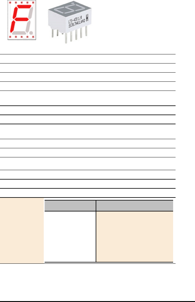
7-segment Display Data Sheet
Title 7-segment Display
TI Item Name STEMEE/AC/DISP/A
Quantity 1
Included in TI-Innovator™ Breadboard Pack
Description Array of LEDs arranged to display numbers and some
alphabetic characters. Also has an LED for a decimal point.
Category LEDs and Displays
Hub Connection breadboard circuit
Assembly
Instructions
Not Applicable
Precautions Not Applicable
Specifications 20mA max per segment, Vf:2V
HUB Commands
Sketch Object DIGITAL.OUT
Command Syntax Send("SET DIGITAL.OUT n ON") - n = 1 to 7
Code
Sample: Desired Action Code Sample
Configure the
program to use 7
DIGITAL.OUT on
pins BB 1 - 7
For (N, 1, 7)
Send("CONNECT
DIGITAL.OUT eval(N) TO
BB eval(N)")
Send("SET DIGITAL.OUT
eval(N) ON")
End
TI-Innovator™ Breadboard Data Sheets 83
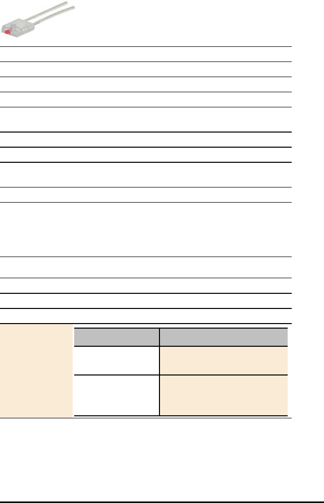
84 TI-Innovator™ Breadboard Data Sheets
Infrared Receiver Data Sheet
Title Infrared Receiver
TI Item Name STEMEE/AC/REC/A
Quantity 1
Included in TI-Innovator™ Breadboard Pack
Description Side emitting Infrared LED, designed to be paired with the
LTR-301 Photo-Transistor.
Category LEDs and Displays
Hub Connection breadboard circuit
Assembly
Instructions
Not Applicable
Precautions Not Applicable
Specifications Power Dissipation: 100mW, Peak Formard Current: 3A with
300 x 1μs pulses per second, Continuous Forward Current:
50 mA, Reverse Voltage: 5V, Forward Voltage: 1.2V,
Operating Temperature Range: -55°C - 100°C, Peak
Wavelength: 940 nM, Viewing Angle: 40°
HUB Commands
Sketch Object DIGITAL.IN
Command Syntax Send("READ DIGITAL.IN n")
Code
Sample: Desired Action Code Sample
Send("CONNECT
DIGITAL.IN 1 TO BB 2")
Send("READ DIGITAL.IN
1")
Get(D):Disp D
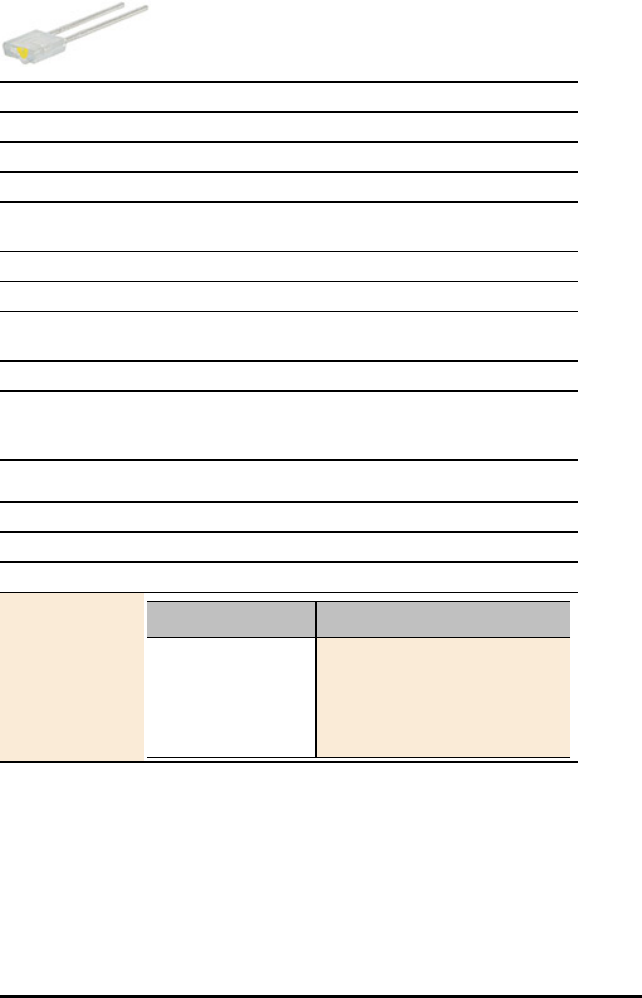
Infrared Transmitter Data Sheet
Title Infrared Transmitter
TI Item Name STEMEE/AC/TRANS/A
Quantity 1
Included in TI-Innovator™ Breadboard Pack
Description Side sensing Infrared photo transistor, designed to be
paired with the LTE-301 Infrared Emitter.
Category LEDs and Displays
Hub Connection breadboard circuit
Assembly
Instructions
Not Applicable
Precautions Not Applicable
Specifications Power Dissipation: 100mW, Collector-Emitter Voltage: 30V,
Emitter-Collector Voltage: 5V, Operating Temperature: -
40°C to 85°C, Storage Temperature: -55°C to 100°
HUB Commands
Sketch Object DIGITAL.OUT
Command Syntax Send("SET DIGITAL.OUT n ON")
Code
Sample: Desired Action Code Sample
Send("CONNECT
DIGITAL.OUT 1 TO BB
5")
Send("SET DIGITAL.OUT
1 ON")
TI-Innovator™ Breadboard Data Sheets 85

86 TI-Innovator™ Breadboard Data Sheets
Motors
Small DC Motor Data Sheet
Title Small DC Motor
TI Item Name STEMEE/AC/MOTOR/A
Quantity 1
Included in TI-Innovator™ Breadboard Pack
Description Motor that converts direct current electrical power into
mechanical power.
Category Motors
Hub Connection breadboard circuit
Assembly
Instructions
Not Applicable
Precautions Not Applicable
Specifications Nominal Voltage: 4.7V, Operating Voltage: 2.0-5.5V, No
Load Speed: 19900 r/min, No Load Current: 0.11A, At
Maximum Efficiency of Torque: 0.14mN.m (1.4g.cm), At
Maximum Efficiency of Output: 0.23W, Stall Torque:
0.7mN.m(7.1g.cm), Stall Current: 0.42A
HUB Commands
Sketch Object DCMOTOR
Command Syntax Send("SET DCMOTOR n TO frequency [duty [TIME] seconds]
")
frequency - 1 to 500Hz duty - 1 to 99%
duty cycle (default: 50%)
seconds = 1s default

HUB Commands
Code
Sample: Desired Action Code Sample
Send("SET DCMOTOR 1 TO
50 TIME 5")
TI-Innovator™ Breadboard Data Sheets 87

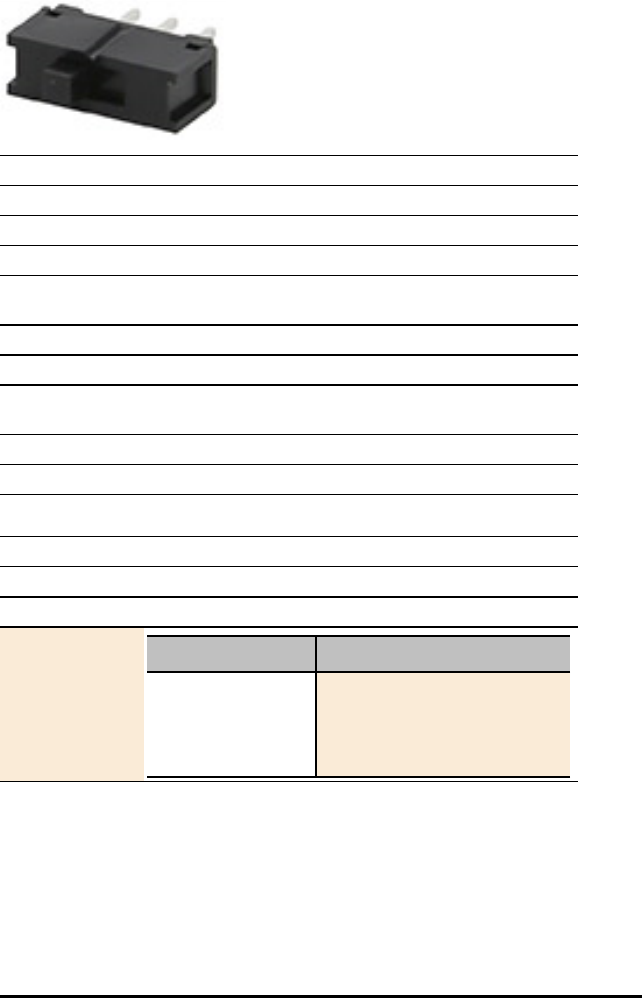
SPDT Slide Switch Data Sheet
Title SPDT Slide Switch
TI Item Name STEMEE/AC/SWIT/A
Quantity 1
Included in TI-Innovator™ Breadboard Pack
Description Single pole, double throw switch. Slide the switch knob
back and forth to open and close contacts.
Category Power and Signal Control
Hub Connection breadboard circuit
Assembly
Instructions
Not Applicable
Precautions Not Applicable
Specifications 30V, 200mA
HUB Commands
Sketch Object SWITCH
Command Syntax Send("READ SWITCH n")
Code
Sample: Desired Action Code Sample
Configure the
program to use
SWITCH on port BB
1
Send("CONNECT SWITCH 1
TO BB 1")
Send("READ SWITCH 1")
Get(T):Disp T
TI-Innovator™ Breadboard Data Sheets 89
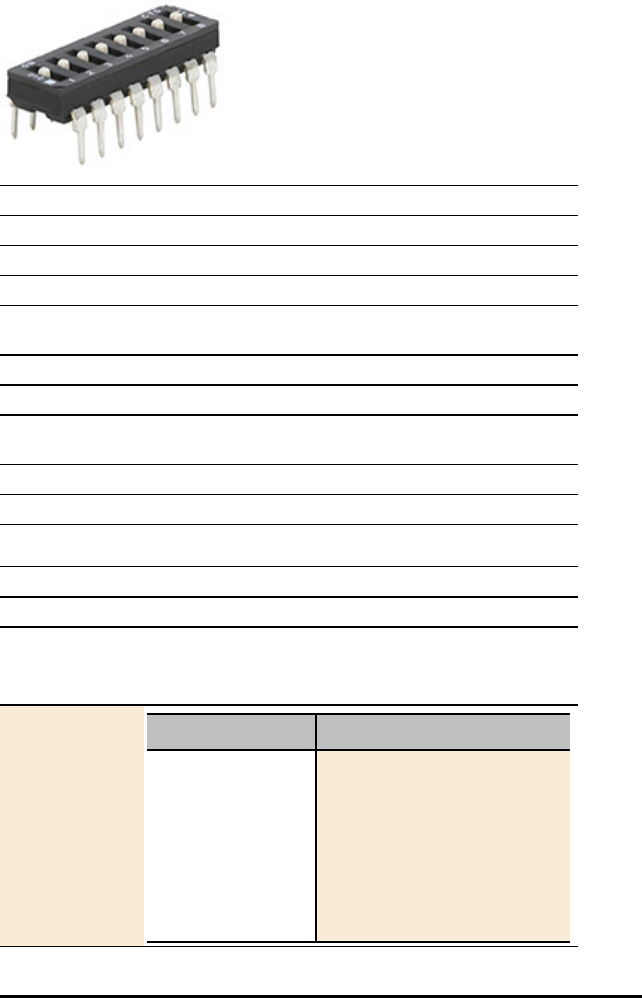
90 TI-Innovator™ Breadboard Data Sheets
8 Position DIP Switch Data Sheet
Title 8 Position DIP Switch
TI Item Name STEMEE/AC/SWIT/B
Quantity 1
Included in TI-Innovator™ Breadboard Pack
Description Set of 8 slide switches used to customize the behavior of
the circuit components for specific situations.
Category Power and Signal Control
Hub Connection breadboard circuit
Assembly
Instructions
Not Applicable
Precautions Not Applicable
Specifications '0.100", 100mA, 20VDC
HUB Commands
Sketch Object DIGITAL.IN
Command Syntax Send("READ DIGITAL.IN n") - n = 1 to 8
or
Send("READ SWITCH n") - n = 1 to 8
Code
Sample: Desired Action Code Sample
Configure the
program to use 8
SWITCHs on pins BB
1 - 8
For (N, 1, 8)
Send("CONNECT SWITCH
eval(N) TO BB eval(N)
")
Send("READ SWITCH eval
(N)")
Get(S):Disp S
End

TI-Innovator™ Breadboard Data Sheets 91

92 TI-Innovator™ Breadboard Data Sheets
8 100 Ohm Resistor SIP Package Data Sheet
Title 8 100 Ohm resistor SIP Package
TI Item Name STEMEE/AC/RES/E
Quantity 1
Included in TI-Innovator™ Breadboard Pack
Description 8 100 Ohm resistor SIP package for use with the 8 Position
DIP Switch.
Category Power and Signal Control
Hub Connection breadboard circuit
Assembly
Instructions
Not Applicable
Precautions Not Applicable
Specifications Bussed array
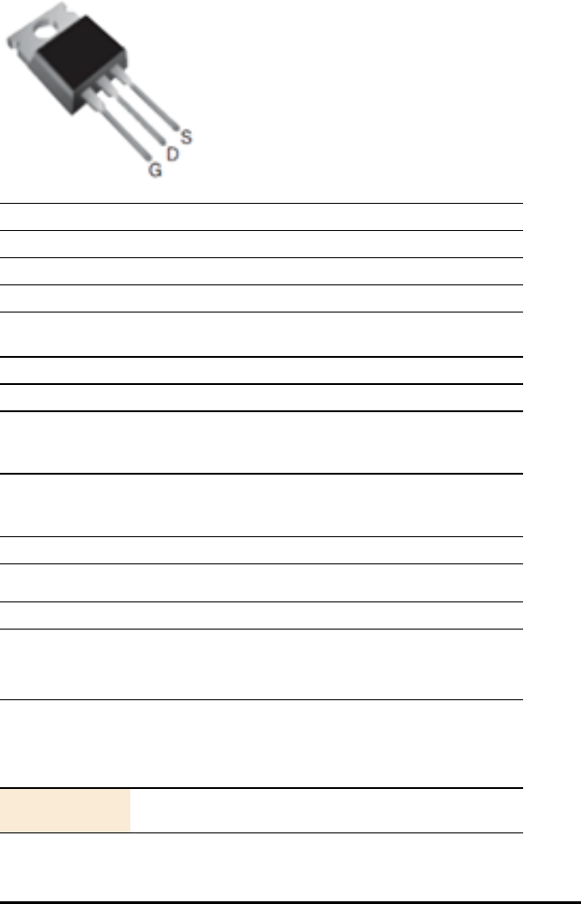
TTL Power MOSFET Data Sheet
Title TTL Power MOSFET
TI Item Name STEMEE/AC/MOSFET/A
Quantity 2
Included in TI-Innovator™ Breadboard Pack
Description Transistorused for amplifying or switching
electronicsignals.
Category Power and Signal Control
Hub Connection breadboard circuit
Assembly
Instructions
Connect the G-GATE to the BB pin of the TI-Innovator™
Hub, the D-DRAIN to the load being controlled (e.g., DC
motor) and the S-SINK to ground.
Precautions If the metal plate on the MOSFET becomes hot during use,
disconnect the battery immediately and re-check all
connections.
Specifications supports 100A
HUB Commands
Sketch Object RELAY
or
ANALOG.OUT
Command Syntax Send("SET RELAY n TO ON/OFF [[TIME] seconds]")
or
Send("SET ANALOG.OUT n TO 0-255/ON/OFF [[BLINK]
frequency] [[TIME] seconds]")
Code
Sample:
Note: a MOSFET can either be used as an ON/OFF control
(RELAY) or for finer control (ANALOG.OUT)
TI-Innovator™ Breadboard Data Sheets 93

94 TI-Innovator™ Breadboard Data Sheets
HUB Commands
Desired Action Code Sample
Send("CONNECT RELAY 1
TO BB 7")
Send("SET RELAY 1 ON")
Send("CONNECT
ANALOG.OUT 1 TO BB 7")
Send("SET ANALOG.OUT 1
127")


96 TI-Innovator™ Breadboard Data Sheets
Accessories
40-Pack Male to Male Breadboard Jumper Cable Data Sheet
Title 40-Pack Male to Male Breadboard Jumper Cables
TI Item Name STEMEE/AC/CABKT/A
Quantity 40
Included in TI-Innovator™ Breadboard Pack
Description Male to Male jumper cables for connecting components on
the breadboard.
Category Accessories
Hub Connection breadboard circuit
Assembly
Instructions
Not Applicable
Precautions Cable lead may break if bent repeatedly
Specifications Male to Male
Pack of 40, 20cm
10-Pack Male to Female Breadboard Jumper Cable Data Sheet
Title 10-Pack Male to Female Breadboard Jumper Cables
TI Item Name STEMEE/AC/CABKT/B
Quantity 10
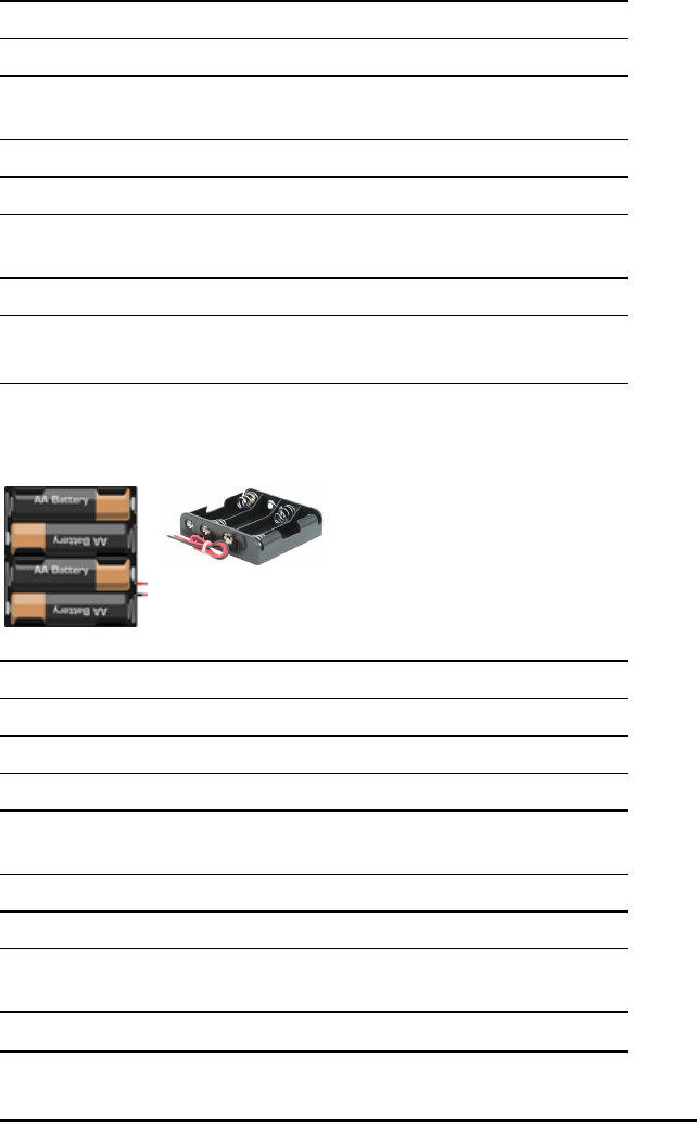
Title 10-Pack Male to Female Breadboard Jumper Cables
Included in Innovator™ Breadboard Pack
Description Male to female jumper cables for connecting components
on the breadboard.
Category Accessories
Hub Connection breadboard circuit
Assembly
Instructions
Not Applicable
Precautions Cable lead may break if bent repeatedly
Specifications Male to Female
Pack of 10, 20cm
4-AA Battery Holder Data Sheet
Title 4-AA Battery Holder
TI Item Name STEMEE/AC/BATHLD/A
Quantity 1
Included in Innovator™ Breadboard Pack
Description 4-AA battery holder with tined solid leads for easy
breadboard insertion.
Category Accessories
Hub Connection breadboard circuit
Assembly
Instructions
Not Applicable
Precautions Not Applicable
TI-Innovator™ Breadboard Data Sheets 97

98 TI-Innovator™ Breadboard Data Sheets
Title 4-AA Battery Holder
Specifications BHC-341-1A with lead wires 150mm, Strip & Tin: 5mm+/-
1mm, UL1007, AWG 26
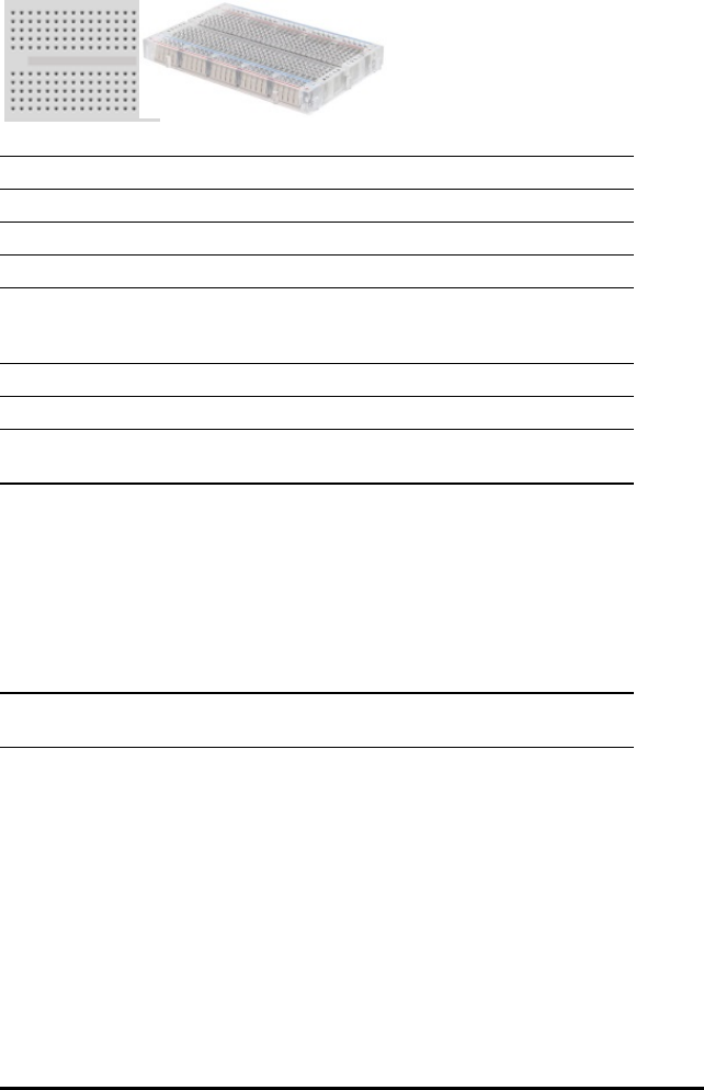
Breadboard Data Sheet
Title Breadboard
TI Item Name STEMEE/AC/BRDBD/A
Quantity 1
Included in TI-Innovator™ Breadboard Pack
Description Platform for connecting the electronic components of a
project by inserting component leads and jumper cables
into pins.
Category Breadboard
Hub Connection breadboard circuit
Assembly
Instructions
Not Applicable
Precautions Do not connect the positive and negative leads of a power
source to the same group of 5 pins on the breadboard.
Doing so could damage the breadboard and the power
source. Observe the correct polarity: When connecting the
breadboard to the Hub. When connecting components that
are sensitive to polarity, such as LEDs and the TTL Power
MOSFET.
See also: TI-Innovator™ Hub Ports and Breadboard Usable
Pins
Specifications 45.7x35.6x9.4mm, 170 tie-point, POM plastic (150℃),
Round Hole, with screwsx2pcs
TI-Innovator™ Breadboard Data Sheets 99

100 TI-Innovator™ Breadboard Data Sheets
Capacitors
Capacitor 100µF Data Sheet
Title Capacitor 100µF
TI Item Name STEMEE/AC/CAP/A
Quantity 1
Included in TI-Innovator™ Breadboard Pack
Description Capacitor that temporarily stores an electric charge of up to
100µF.
Category Capacitors
Hub Connection breadboard circuit
Assembly
Instructions
Longer leg (lead) is positive (anode). If both leads are of
equal length, the lead adjacent to the colored strip on the
casing is the negative (cathode) lead.
Precautions Not Applicable
Specifications Capacitance: 100µF, Tolerance: ±20%, Voltage Rating: 16V
Capacitor 10µF Data Sheet
Title Capacitor 10µF
TI Item Name STEMEE/AC/CAP/B
Quantity 1
Included in Innovator™ Breadboard Pack
Description Capacitor that temporarily stores an electric charge of up to
10µF.
Category Capacitors
Hub Connection breadboard circuit

Title Capacitor 10µF
Assembly
Instructions
Longer leg (lead) is positive (anode). If both leads are of
equal length, the lead adjacent to the colored strip on the
casing is the negative (cathode) lead.
Precautions Not Applicable
Specifications Capacitance: 10µF, Tolerance: ±20%, Voltage Rating: 16V
Capacitor 1µF Data Sheet
Title Capacitor 1µF
TI Item Name STEMEE/AC/CAP/C
Quantity 1
Included in Innovator™ Breadboard Pack
Description Capacitor that temporarily stores an electric charge of up to
1µF.
Category Capacitors
Hub Connection breadboard circuit
Assembly
Instructions
Longer leg (lead) is positive (anode). If both leads are of
equal length, the lead adjacent to the colored strip on the
casing is the negative (cathode) lead.
Precautions Not Applicable
Specifications Capacitance: 1µF, Tolerance: ±20%, Voltage Rating: 16V
TI-Innovator™ Breadboard Data Sheets 101
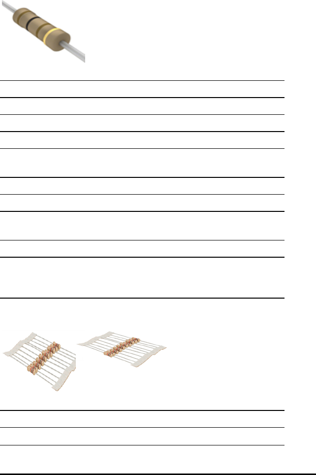
102 TI-Innovator™ Breadboard Data Sheets
Resistors
Resistor 100 Ohm Data Sheet
Title Resistor 100 Ohm
TI Item Name STEMEE/AC/RES/A
Quantity 10
Included in TI-Innovator™ Breadboard Pack
Description Resistor that provides 100 Ohms of resistance in a circuit.
Color Code Value: brown, black, brown.
Category Resistors
Hub Connection breadboard circuit
Assembly
Instructions
No polarity
Precautions Not Applicable
Specifications 'Resistance (Ohms): 100, Tolerance: ±5%, Power (Watts):
0.5W, 1/2W, Temperature Coefficient: 0/ -400ppm/°C,
Operating Temperature: -55°C ~ 155°C
Resistor 1K Ohm Data Sheet
Title Resistor 1K Ohm
TI Item Name STEMEE/AC/RES/B
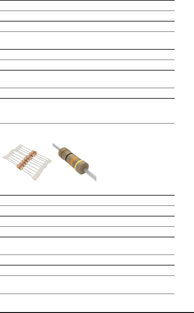
Title Resistor 1K Ohm
Quantity 10
Included in TI-Innovator™ Breadboard Pack
Description Resistor that provides 1K Ohms of resistance in a circuit.
Color Code Value: brown, black, red.
Category Resistors
Hub Connection breadboard circuit
Assembly
Instructions
No polarity
Precautions Not Applicable
Specifications 'Resistance (Ohms): 1K, Tolerance: ±5%, Power (Watts):
0.5W, 1/2W, Temperature Coefficient: 0/ -400ppm/°C,
Operating Temperature: -55°C ~ 155°C
Resistor 10K Ohm Data Sheet
Title Resistor 10K Ohm
TI Item Name STEMEE/AC/RES/C
Quantity 10
Included in TI-Innovator™ Breadboard Pack
Description Resistor that provides 10K Ohms of resistance in a circuit.
Color Code Value: brown, black, orange.
Category Resistors
Hub Connection breadboard circuit
Assembly
Instructions
No polarity
TI-Innovator™ Breadboard Data Sheets 103

104 TI-Innovator™ Breadboard Data Sheets
Title Resistor 10K Ohm
Precautions Not Applicable
Specifications 'Resistance (Ohms): 10K, Tolerance: ±5%, Power (Watts):
0.5W, 1/2W, Temperature Coefficient: 0/ -400ppm/°C,
Operating Temperature: -55°C ~ 155°C
Resistor 100K Ohm Data Sheet
Title Resistor 100K Ohm
TI Item Name STEMEE/AC/RES/D
Quantity 10
Included in TI-Innovator™ Breadboard Pack
Description Resistor that provides 100K Ohms of resistance in a circuit.
Color Code Value: brown, black, yellow.
Category Resistors
Hub Connection breadboard circuit
Assembly
Instructions
No polarity
Precautions Not Applicable
Specifications 'Resistance (Ohms): 100K, Tolerance: ±5%, Power (Watts):
0.5W, 1/2W, Temperature Coefficient: 0/ -400ppm/°C,
Operating Temperature: -55°C ~ 155°C

Resistor 10M Ohm Data Sheet
Title Resistor 10M Ohm
TI Item Name STEMEE/AC/RES/F
Quantity 10
Included in TI-Innovator™ Breadboard Pack
Description Resistor that provides 10M Ohms of resistance in a circuit.
Color Code Value: brown, black, blue.
Category Resistors
Hub Connection breadboard circuit
Assembly
Instructions
No polarity
Precautions Not Applicable
Specifications 'Resistance (Ohms): 10M, Tolerance: ±5%, Power (Watts):
0.5W, 1/2W, Temperature Coefficient: 0/ -400ppm/°C,
Operating Temperature: -55°C ~ 155°C
Potentiometer with Knob Data Sheet
Title Potentiometer with Knob
TI Item Name STEMEE/AC/POTEN/A
Quantity 1
Included in TI-Innovator™ Breadboard Pack
Description Variable resistor with knob used to change the resistance in
TI-Innovator™ Breadboard Data Sheets 105
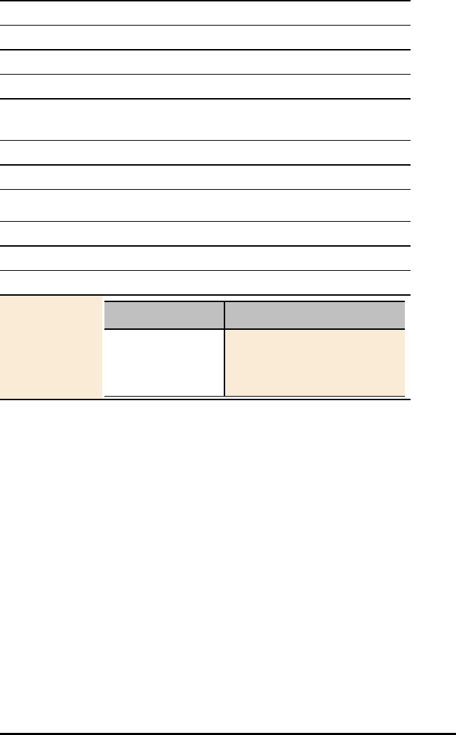
106 TI-Innovator™ Breadboard Data Sheets
Title Potentiometer with Knob
a circuit.
Category Resistors
Hub Connection breadboard circuit
Assembly
Instructions
Not Applicable
Precautions Not Applicable
Specifications 1 Turn, 10K
HUB Commands
Sketch Object POTENTIOMETER
Command Syntax Send("READ POTENTIOMETER n")
Code
Sample: Desired Action Code Sample
Read potentiometer Send("READ
POTENTIOMETER 1")
Get(P):Disp P

Frequently Asked Questions
This section includes some of the frequently asked questions we have received about
the
TI-Innovator™ Technology. Don’t see your question? Send feedback to the eGuide team.
hubeguide@list.ti.com
Topic Links
•Product Configuration Information
•Product Compatibility Information
•TI-Innovator™ Ports Information
•General TI-Innovator™ Rover Information
•TI-Innovator™ Hub App for the TI-84 Plus CE
•Updating Sketch on the TI-Innovator™ Hub
•TI LaunchPad™ Information
•General Activity Information
•General Power Information for TI-Innovator™ Hub
•External Battery Information for TI-Innovator™ Hub
•TI-Innovator™ Rover Battery Information
•TI-Innovator™ Hub On-Board Components Details
•TI-Innovator™ Rover On-Board Components Details
•I/O Module Details
•Breadboard Components Details
Frequently Asked Questions 107

108 Frequently Asked Questions
Product Configuration Information
What are the TI-Innovator™ configurations that are available for sale?
- TI-Innovator™ Hub Kit
- TI-Innovator™ Rover
- TI-Innovator™ I/O Module Pack
- TI-Innovator™ Breadboard Pack
- Ultrasonic Ranger Module
- External Battery
What is included with the TI-Innovator™ Rover?
- TI-Innovator™ Rover
- Breadboard Ribbon Cable
- I2C Cable
What is included in the TI-Innovator™ Hub Kit?
The TI-Innovator™ Hub Kit contains the following:
- TI-Innovator™ Hub
- TI Wall Charger
- USB Cable – Standard-A to Micro-B
- USB Cable – Mini-A to Mini-B
- USB Cable – Standard-A to Mini-B
What is included in the TI-Innovator™ I/O Module Pack?
The TI-Innovator™ I/O Module Pack contains the following:
- Light Sensor module with detachable cable
- LED module with detachable cable
- Vibration Motor module with detachable cable
- Servo Motor with attached cable
See I/O Module section for more detail.
What is included in the TI-Innovator™ Breadboard Pack?
The TI-Innovator™ Breadboard Pack contains the following:
– Breadboard 2 x 3 inches – 940nm Infrared
transmitter and
receiver
– Forty (40) – Male to Male breadboard
jumper cables (20 cm)
– Thermistor
– Ten (10) – Male to Female breadboard
jumper cables
– Analog temperature
sensor

– Assorted LEDs (five (5) green, ten (10)
red, two (2) RGB)
– Potentiometer with
knob
– Assorted resistors (ten (10) each of 100
Ohm, 1K Ohm, 10K Ohm, 100K Ohm,
10M Ohm)
– Small DC motor
– Assorted capacitors (one (1) each of
100 µF, 10 µF, 1 µF)
– Diode
– 7 segment display – Light sensor
– SPDT slide switch
– 8-Position DIP switch
– 8 100 Ohm resistor SIP
packages
– Two (2) Power
MOSFET
– 4AA battery holder
See Breadboard section for more detail.
What is included with the Ultrasonic Ranger Module?
- Ultrasonic Ranger Module with detachable cable.
See I/O Module section for more detail.
What is included with the External Battery Kit?
- This kit only contains the External Battery (Model # MP-3000).
See Battery section for more detail.
Frequently Asked Questions 109

110 Frequently Asked Questions
Product Compatibility Information
What TI products will work with the TI-Innovator™ Hub?
The TI-Innovator™ Hub is compatible with the following TI products. For best results
always use the latest version of the TI-Innovator sketch and compatible products.
- TI CE Graphing Calculator
- TI-Nspire™ CX handheld
- TI-Nspire™ CX CAS handheld
- TI-Nspire™ CX computer software (Student, Teacher, and TI-Nspire™ CX
Navigator™)
What programming language is compatible with the TI-Innovator™ Hub?
The TI-Innovator™ Hub can be programmed through the programming language TI
BASIC on both the TI CE graphing calculators and TI-Nspire™ CX calculators. This
programming language is used in several TI CE graphing calculators and is based on
the BASIC (Beginner's All-purpose Symbolic Instruction Code) programming language.
BASIC is a family of general-purpose, high-level programming languages whose design
philosophy emphasizes ease of use.
In addition, with TI-Nspire™ CX technology you can use LUA programming which is a
powerful, fast scripting language.
See Also: Hub Programming on TI CE Graphing Calculator for details.
See Also: Hub Programming on TI-Nspire™CX Technology for details.
What sensors, actuators, etc. can I connect to the TI-Innovator™ Hub?
The TI-Innovator™ Hub has two types of connectors:
- Universal 4-pin connector that is compatible with an array of modules.
- Breadboard connector that can be connected to a breadboard for prototyping
projects.
To easily get started, we have convenient kits that contain all the components you
need to complete the activities. See the sections related to the I/O Module and
Breadboard for details.
Can the TI-Nspire™ Lab Cradle with Vernier™ sensors be used while using the TI-
Innovator™ Hub?
Yes, the TI-Nspire™ Lab Cradle can be used concurrently with the TI-Innovator™ Hub on
TI-Nspire™ CX Handheld or TI-Nspire™ CX software. To use both the TI-Innovator™ Hub
and TI-Nspire™ Lab Cradle at the same time, they must be accessed via a LUA script.
Can I plug Vernier™ sensors directly into the TI-Innovator™ Hub?
The TI-Innovator™ Hub ports are not directly compatible with the Vernier™ sensors. The
Vernier™ sensors can be connected to a TI-Nspire™ Lab Cradle. To use both the TI-
Innovator™ Hub and TI-Nspire™ Lab Cradle at the same time, they must be accessed
via a LUA script.

Can the TI-Nspire™ CX Navigator™ System be used while using the TI-Innovator™
Hub?
Yes, students can have their TI-Nspire™ CX handheld connected to the TI-Nspire™ CX
Navigator™ system while using the TI-Innovator™ Hub. The teacher can use TI-Nspire™
CX Navigator™ functionality, including Live Presenter, Screen Capture, Quick Poll, etc.
while students are using the TI-Innovator™ Hub.
Can TI Connect™ CE or TI-SmartView™ CE software communicate with the TI-
Innovator™ Hub?
The TI-Innovator™ Hub cannot communicate directly with the TI Connect™ CE software
or TI-SmartView™ CE software. However, you can use TI Connect™ CE software to
write programs for use with the TI-Innovator™ Hub. TI-SmartView™ CE software is a
great way to demo the programming steps to your students.
TI-Innovator™ Ports Information
What connection ports are available, and what can they connect to?
See What's in the Box for details.
What is the difference between the two USB ports?
-DATA: This is a mini-USB port, labeled "DATA B", that is used to connect to
the TI graphing calculator, or a computer running TI-Nspire™ CX software. The
USB port is located on the same side as the Light Sensor.
-POWER: This USB port, labeled “PWR,” is located on the same side as the
Breadboard connector. This is a micro-USB port that is used for two purposes.
1. Connect to external power source (TI Wall Adapter and TI-Innovator™
External Battery) when using components that require 5V (e.g., motor).
2. Connect to computer USB port to update the TI-Innovator™ sketch.
General TI-Innovator™ Rover Information
What TI products will work with the TI-Innovator™ Rover?
The TI-Innovator™ Rover is compatible with the following TI products. For best results
always use the latest version of the TI-Innovator sketch and compatible products.
- TI-84 Plus CE calculator
- TI-Nspire™ CX handheld
- TI-Nspire™ CX CAS handheld
- TI-Nspire™ CX computer software (Student, Teacher, and TI-Nspire™ CX
Navigator™)
What are the features of the TI-Innovator™ Rover?
- Two independently controllable motors with high resolution motor shaft
encoder sensors to count revolutions
- Front mounted ranger for measuring distance to obstacles
- Bottom mounted color sensor to measure color
Frequently Asked Questions 111

112 Frequently Asked Questions
- Red Green Blue (RGB) LED on top to display programmable feedback to user
- High-capacity, rechargeable battery to meet the needs of classroom use
- Calculator Holder Pegs - For securing a TI CE Graphing Calculator or a TI-
Nspire™ CX Handheld to the calculator platform.
- Allows use of TI-Innovator speaker, light brightness sensor, and input and
output ports
- Gyroscope to measure heading
- Tracks mathematical coordinates, time, heading, and distance for each
segment in travel history for analysis
- Marker holder for drawing paths on paper
What type of marker does Rover work with?
Thin markers or dry erase markers should work with the Rover marker holder. Adding
masking tape to markers that are too thin may improve performance.
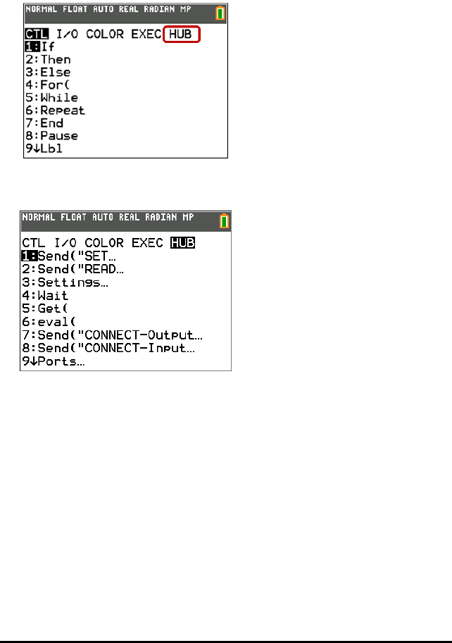
TI-Innovator™ Hub App for the TI CE Graphing Calculator(s)
What is the TI-Innovator™ Hub App?
The TI-Innovator™ Hub App adds the HUB menu to the programming menu on a TI CE
graphing calculator.
This menu option makes it easy to select commands that are commonly used when
creating programs to use with the TI-Innovator™ Hub.
How do I know whether I have the TI-Innovator™ Hub App?
To determine if the Hub app is loaded on your TI CE graphing calculator, follow these
steps.
1. Press 2nd [mem]
2. Select option "2: Mem Management/Delete…"
3. Select option "A: Apps"
4. The TI-Innovator™ Hub App is listed as "Hub" in the list of apps. Confirm that the
Hub is listed.
Frequently Asked Questions 113
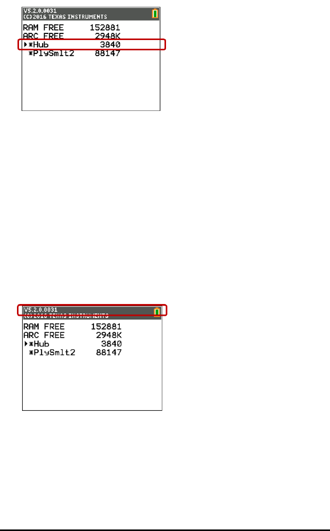
114 Frequently Asked Questions
What version of the TI-Innovator™ Hub App do I need?
For best results always use the latest version of the TI-Innovator™ Hub App and TI-84
Plus CE. Visit education.ti.com/en/product-resources/whats-new-84-ce to get the
latest.
How do I know what the version number of my TI-Innovator™ Hub App is?
To determine the version of the Hub App that is loaded on your TI CE Graphing
Calculator, follow these steps.
1. Press 2nd [mem]
2. Select option "2: Mem Management/Delete…"
3. Select option "A: Apps"
4. Press the down arrow until the Hub app is selected.
5. Look at the title bar to view the version number of the Hub app.
How do I get the TI-Innovator™ Hub App?
The TI-Innovator™ Hub App is available for download from the TI website at
education.ti.com/latest.

Will I need to update the TI-Innovator™ Hub app every time I update the calculator
OS?
The TI-Innovator™ Hub app would only need to be updated when new functionality is
added to the app. However, it is strongly recommended that you always keep your TI
products up to date with the latest OS and versions. When updating your OS always
check to see if any apps have updates as well.
Do I need an app to use the TI-Innovator™ Hub with TI-Nspire™ CX technology?
No. TI-Nspire™ CX technology has all the commands to communicate with the TI-
Innovator™ Hub built in. For best results always use the latest version of TI-Nspire™.
Frequently Asked Questions 115

116 Frequently Asked Questions
Updating Sketch on the TI-Innovator™ Hub
What is the TI-Innovator™ sketch?
The ‘sketch’ is the software on the TI-Innovator™ Hub that communicates with the
graphing calculator, processes the commands, and controls the external components.
Do I need to update the sketch on the TI-Innovator™ Hub?
For best results always use the latest version of TI-Innovator™ sketch. To stay informed
on any updates to the TI-Innovator™ Hub, make sure you register your product at
education.ti.com/register or check the TI-Innovator™ website at
education.ti.com/go/innovator.
What is the latest version of the sketch?
For best results always use the latest version of TI-Innovator sketch. You can always
find the latest version of the sketch at education.ti.com/go/innovator.
Why would I update the sketch?
There are a couple of different reasons to upgrade the sketch.
1. To get the latest version from TI that may include new functionality.
2. To restore the TI sketch after loading a custom sketch – This is only needed by
advanced users who use an alternative sketch.
How do I load the sketch on the TI-Innovator™ Hub?
The sketch can be updated through the TI-Innovator Hub Update Software. This
software is a free download on the TI website.
Can I update multiple TI-Innovator Hubs at the same time?
The TI-Innovator Hub Update Software only allows updating a single Hub at a time.
However, the application is designed to allow you to update multiple Hubs without
having to re-launch the software.
How do I know what version of the sketch I have?
The latest versions of the calculator operating systems have new functionality that will
show you the version of sketch on a connected Hub.
TI-Nspire™ CX handhelds or software
1. Connect your TI-Innovator Hub to the handheld or the computer through a USB
cable
2. Make sure to connect to the Hub’s DATA port
3. Click the ‘Home/On’ button, then “5: Settings” and “7:TI-Innovator Hub”. The dialog
will show the version number of the sketch.
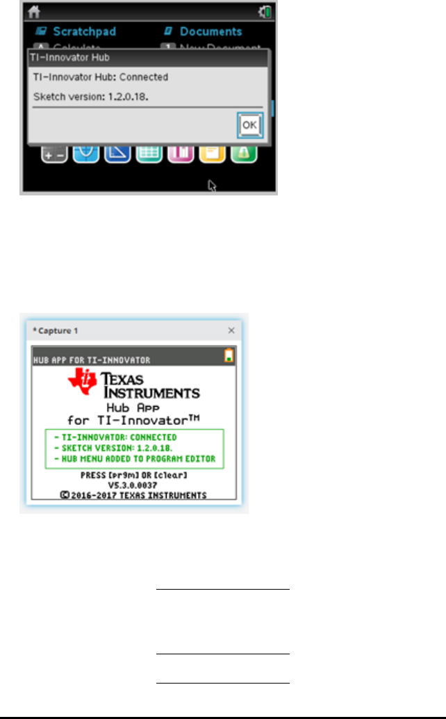
TI-84 Plus CE:
1. Connect your TI-Innovator Hub to the graphing calculator through a USB cable
2. Make sure to connect to the Hub’s DATA port
3. Click the APPS button and then select the ‘Hub’ app.
The app will display the sketch version of the connect TI-Innovator Hub.
For previous versions of calculator OSs, you can use programming commands to
identify the version number of the sketch loaded on the TI-Innovator™ Hub. Use the
"VERSION" command on the Hub Manage menu to return the version number of the
sketch on the TI-Innovator™ Hub.
TI-Nspire™
CX
handhelds
or
software:
TI-84 Plus
CE:
GetStr
"VERSIO
Send
("VERSIO
Frequently Asked Questions 117

118 Frequently Asked Questions
TI-Nspire™
CX
handhelds
or
software:
TI-84 Plus
CE:
N", ver N")
Disp ver Get(Str1)
Disp Str1
What are the system requirements for upgrading?
Windows OS Windows® 7 SP1
Windows 8.1 Update 1
Windows 8.1 Update 1 Pro
Windows 10
Compatible with 32-bit and 64-bit Operating Systems
Processor Intel Core i3 or higher generation processor (Except
Intel Atom)
RAM 2GB
Free hard drive space 100 MB
Screen resolution 1024 x 768 (minimum) - 3840 x 2160 (maximum)
Other requirements: Available USB Port
Active internet connection for installation
Mac OS Mac® OS X 10.11
macOS 10.12, 10.13
Processor Any Mac 2008 or newer
RAM 2GB
Free hard drive space 100 MB
Screen resolution 1024 x 768 (minimum) - 3840 x 2160 (maximum)
Other requirements: Available USB Port
Active internet connection for installation
Can the sketch that comes on the TI-Innovator™ Hub be edited to add functionality but
still work with the TI calculator? Is the sketch open source?
The code for sketch that is loaded on the TI-Innovator™ has not been published for
others to modify or edit. To maintain compatibility between the TI-Innovator™ Hub and
TI calculator products, only use the officially published sketch for TI-Innovator™ Hub.

TI LaunchPad™ Information
What is a TI LaunchPad™ development kit?
TI LaunchPad kits are a range of microcontroller development kits (also called
evaluation boards) from Texas Instruments. To learn more there is a lot of detail
regarding the TI LaunchPad ecosystem at
http://www.ti.com/ww/en/launchpad/about.html.
What TI LaunchPad™ kit is used in the TI-Innovator™ Hub?
The TI-Innovator™ Hub is powered by a MSP432P401 TI LaunchPad kit. More
information on the MSP432P401 LaunchPad is at
http://www.ti.com/ww/en/launchpad/launchpads-msp430-msp-
exp432p401r.html#tabs.
Can I use the TI-Innovator™ Hub as a TI LaunchPad™ development kit?
While the TI-Innovator™ Hub can be used as TI LaunchPad™ Board, the TI-Innovator™
Hub was specifically designed to be used by students learning how to code, build, and
explore using electronics. More information on TI LaunchPad can be found at
http://www.ti.com/ww/en/launchpad/about.html.
What resources are available for the TI LaunchPad?
If you are interested in the TI LaunchPad ecosystem, you can find resources at
http://www.ti.com/ww/en/launchpad/about.html
How are development kits/engineering boards used by engineers in the real word?
Engineers use evaluation boards like the TI LaunchPad™ boards to prototype their
designs and verify the suitability of a particular chip for their design. These boards
allow engineers to try different approaches before finalizing their design. The boards
also help the engineers measure other aspects of their designs, such as power
consumption and speed of operations.
These evaluation boards are also used in universities to learn about microcontrollers,
programming, and interfacing with sensors.
Frequently Asked Questions 119

120 Frequently Asked Questions
General Activity Information
What activities are available for the TI-Innovator™ Hub?
There are multiple activities available to use with the TI-Innovator™ Hub. Working with
educators we have created activities around the following themes:
10 Minutes of Code for TI-Innovator™ Hub: Engage students in short activities that
build understanding of math concepts, programming logic, and coding skills.
Activities use the built-in RGB, LED, Speaker, and Light Brightness Sensor of the TI-
Innovator™ Hub. Activities are available for the TI-84 Plus CE and TI-Nspire™ CX
technology.
10 Minutes of Code for TI-Innovator™ Rover: Continue learning to code with the TI-
Innovator™ Rover. Build on your knowledge of programming the TI-Innovator™ Hub
and write programs to control the TI-Innovator™ Rover. Learn the commands to
make the Rover move and use its built-in ranger and color sensor. Activities will be
available for the TI-84 Plus CE and TI-Nspire™ CX technology.
Math and Science Classroom “Conversations” for TI-Innovator™ Rover: Ready-to-use
programs for the TI-84 Plus CE and TI-Nspire™ CX technology. These programs will
include a usage guide for the teacher that will provide suggestions on how to
implement the TI-Innovator™ Rover with the program(s) provided to explore
concepts in the math and/or science classroom.
Science through Engineering Design: Rich, interactive lessons for middle grades
students in life and physical science. Uses components provided in the TI-
Innovator™ I/O Module Pack. Activities are available for TI-Nspire™ CX technology.
Path to STEM Projects: Design, build, test, refine. These sequential activities
engage middle grade and high school students in engineering principles, providing
students with the basic knowledge and skills required to synthesize new and
unique STEM projects. These activities require the components provided in the TI-
Innovator™ Breadboard Pack. Activities are available for the TI-84 Plus CE and TI-
Nspire™ CX technology.
Where can I download activities for the TI-Innovator™ Hub?
Activities for use with the TI-Innovator™ Hub can be found at the education.ti.com
website, under the Activities tab at the top of each page. Direct links to each set of
activities are as follows:
- 10 Minutes of Code with TI-Innovator™ Hub: education.ti.com/ticodes
- 10 Minutes of Code with TI-Innovator™ Rover: education.ti.com/ticodes
- Math and Science Classroom “Conversations” for TI-Innovator™ Rover:
- Science through Engineering Design:
https://education.ti.com/en/tisciencenspired/us/stem
- Path to STEM Projects: TBD

When will the activities be available?
The activities for the TI-Innovator™ Hub are now available. Activities for the TI-
Innovator™ Rover will be available in Fall 2017.
Frequently Asked Questions 121

122 Frequently Asked Questions
General Power Information for TI-Innovator™ Hub
How is the TI-Innovator™ Hub powered?
The TI-Innovator™ Hub is powered by the batteries in the TI CE graphing calculator or
the TI-Nspire™ CX handheld. In certain activities with high-powered devices such as
servo motors, you may need to use an auxiliary power source – either the TI Wall
Adapter or External Battery.
How does the TI-Innovator™ Hub affect the TI CE Graphing Calculator or TI-Nspire™ CX
battery life?
The TI-Innovator™ Hub has a minimal impact on the battery of the TI CE graphing
calculator or TI-Nspire™ CX graphing calculators.
When do I need to use the external power?
When using the Input and Output ports:
Certain I/O Modules require external power, as they use the 5V (OUT3 or IN3)
ports on the TI-Innovator™ Hub. See the I/O Module section for details.
When using the Breadboard connector:
A circuit that is powered from the 5V output of the breadboard connector will
require external power.
What options are available for external power?
You can use the TI Wall Adapter or the External Battery for additional power. The TI
Wall Adapter comes with the TI-Innovator™ Hub and is the same wall charger that is
provided with the TI CE graphing calculator and TI-Nspire™ CX calculators. The External
Battery is sold separately as an accessory for the TI-Innovator™ Hub.
Can I use a different battery/power supply with the TI-Innovator™ Hub?
You should only use the battery and power supply provided by TI to ensure safe
operation.

External Battery Information for TI-Innovator™ Hub
What is the external battery?
The External Battery provides additional power for those components that require
more power than can be provided via the TI graphing calculator. This battery (Model #
MP-3000) was selected to meet TI-Innovator™ component power needs.
How do you use the External Battery with the TI-Innovator™ Hub?
Using the Standard-A to Micro-B USB cable provided with the TI-Innovator™ Hub, the
external battery should be connected to the PWR USB port on the TI-Innovator™ Hub.
The external battery has an On/Off switch that must be turned on to provide power the
TI-Innovator™ Hub.
How long will the battery last on a full charge?
The battery life will depend on the components attached to the TI-Innovator™ Hub. For
example, the Servo Motor Module that is used with the Science through Engineering
Design activities can run for 8 hours of continuous use using the external battery. Other
components could last longer or drain the battery more rapidly.
What is the expected lifetime of the battery?
As lithium-ion batteries age, they lose capacity. When properly maintained and under
normal usage, batteries are expected to last about three years.
How do you recharge the battery?
The External Battery can be recharged using the TI Wall Adapter (included with the TI-
Innovator™ Hub) or the USB cable that came with the TI-Innovator Hub plugged into a
computer USB port.
How do I know how charged my battery is?
When you turn the external battery on, the LED battery indicators on the External
Battery will display the approximate battery charge (25%, 50%, 75%, and 100%). The
LEDs turn themselves off after 10 seconds.
Can I use the External Battery with other products?
The External Battery was specifically tested for use with the TI-Innovator™ Hub.
Frequently Asked Questions 123

124 Frequently Asked Questions
Rover Battery Information
How long will the battery last on a full charge?
The battery will last 8 hours of continuous driving. Typical use is expected to include
frequent breaks for programming. In that scenario, a full charge will last several days
of uses.
What is the expected lifetime of the battery?
As lithium-ion batteries age, they lose capacity. When properly maintained and under
normal usage, batteries are expected to last about 3 years.
How do you recharge the battery?
Connect a micro-USB cable to the PWR port on the right front side of the Rover. The
other end of the cable can be connected to a PC or a TI wall charger.
How do I know how charged my battery is?
The four battery level LEDs shows the battery capacity. When all four LEDs are solid
green, the Rover battery is fully charged.
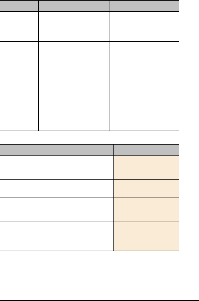
TI-Innovator™ Hub On-Board Components Details
What are the capabilities of the on-board components?
Component Capabilities Details
RGB LED Built-in light-emitting diode
(LED) that is capable of
emitting a variety of colors.
Can control red, blue, and
green levels of intensity (0
to 255) to create a specific
color.
Red LED Built-in light-emitting diode
(LED) that emits a red light.
Can set LED on or off, set
LED to blink and determine
frequency and duration.
Speaker Built-in speaker located at
the back of the Hub. It
converts electrical current
into sound you can hear.
The speaker can emit
sounds from 40 to 4000 Hz.
Light
Brightness
Sensor
Built-in light brightness
sensor located at the
bottom of the Hub. The
sensor detects light
intensity.
Can detect ambient light
brightness. Value is scaled
from 0 (darkness) to 100
(bright sunlight).
What are some examples of using the on-board components?
Component Desired Action Program Code
RGB LED Turn on blue element of on-
board RGB LED ("COLOR") at
100% brightness.
Send "SET
COLOR.BLUE 255"
Red LED Turn on the on-board Red LED
("LIGHT").
Send "SET LIGHT
ON"
Speaker Play a 440Hz tone on the on-
board speaker ("SOUND") for
2 seconds.
Send "SET SOUND
440 TIME 2"
Light
Brightness
Sensor
Read and display the current
value of the on-board light
sensor ("BRIGHTNESS"). Range
is 0% to 100%.
Send "READ
BRIGHTNESS"
Get a: Disp a
Frequently Asked Questions 125
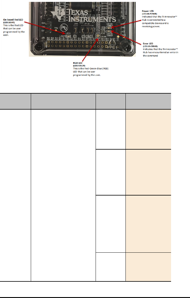
126 Frequently Asked Questions
What are all the LEDs that are built into the TI-Innovator™ Hub?
.
What are the full syntax options for the each of the on-board components?
Component Command Syntax Desired
Action
Code Samples
RGB LED Send("SET COLOR …")
ON/OFF/0-
255 (red
element)
ON/OFF/0-
255
(green
element)
ON/OFF/0-
255 (blue
element)
[BLINK
frequency]
(in Hz)
[TIME
duration]
(in
seconds)
Turn ON
Red and
Green
elements
of tri-color
LED
Send("SET
COLOR ON ON
OFF")
Set Red to
full
intensity,
Green to
half
intensity,
Blue to off
Send("SET
COLOR 255
128 0")
Set Red to
full
intensity,
Green to
half
intensity,
Blue to off
for 10
seconds
Send("SET
COLOR 255
128 0 TIME
10")
Set Red to
full
intensity,
Send("SET
COLOR 255
128 0 BLINK
2 TIME 10")

Component Command Syntax Desired
Action
Code Samples
Green to
half
intensity,
Blue to off
and blink
at 2 Hz (2
times a
second) for
10 seconds
Turn OFF
the Red
element
Send("SET
COLOR.RED
0")
Turn ON
the Green
element at
half
intensity
and blink
it at 2 Hz
(2 times a
second) for
10 seconds
Send("SET
COLOR.GREEN
128 BLINK 2
TIME 10")
Red LED Send("SET LIGHT …")
ON/OFF
[BLINK
frequency]
[TIME
duration]
(in
seconds)
Turn LED
ON
Send("SET
LIGHT ON")
Turn LED
OFF
Send("SET
LIGHT OFF")
Turn LED
ON for 10
seconds
Send("SET
LIGHT ON
TIME 10")
Turn LED
ON, blink
LED at 2
Hz (2
times a
second) for
10 seconds
Send("SET
LIGHT 1
BLINK 2 TIME
10")
Speaker Send("SET SOUND …")
Frequency
in Hz
Play tone
at 261.23
Hz
Send("SET
SOUND
261.23")
Frequently Asked Questions 127

128 Frequently Asked Questions
Component Command Syntax Desired
Action
Code Samples
[TIME
duration
in
seconds]
Evaluate
the
expression
2^8 (=
256) and
play that
tone
Send("SET
SOUND eval
(2^8)")
Evaluate
the
expression
2^8 (=
256) and
play that
tone for
.25 sec
Send("SET
SOUND eval
(2^8) TIME
.25")
Evaluate
the
expression
2^9 (=
512) and
play that
tone for
0.25 s
(result of
evaluating
1/4)
Send("SET
SOUND eval(
2^9) TIME
eval(1/4)")
Turn
speaker off
Send("SET
SOUND OFF")
Light
Brightness
Sensor
Send("READ BRIGHTNESS") Read the
built-in
light
brightness
sensor
Send("READ
BRIGHTNESS")
Get(B)

TI-Innovator™ Rover On-Board Components Details
What are the capabilities of the Rover on-board components?
Component Capabilities Details
2 Motors with
encoders
Move the Rover – forward,
backward, turns – and
measure the distance
traveled.
The rotary encoders – one on
each motor – measure the
distance traveled by the
Rover.
Ultrasonic
Ranger
Measure the distance to an
obstacle.
The front-facing ultrasonic
ranger that measures the
distance
Color Sensor Sense the color of the
surface that the Rover is
driving on.
The color sensor is on the
bottom of the Rover and is
used to detect the color of
the surface.
RGB light
indicator
Display any combination of
red green and blue colors.
The tri-color RGB LED on the
top surface of the Rover can
be controlled through user
programs to display any color
combination
Gyroscope Measures the angular
change in Rover motion
The gyroscope is used to
maintain the heading of Rover
while it’s in motion. It can
also be used to measure the
change in angle during turns.
What are some examples of using the Rover on-board components?
Component Desired Action Program Code
2 Motors
with
encoders
Move RV Forward by .5 M
Move RV Backward by .1 M
Send "RV FORWARD 0.5
M"
Send "RV BACKWARD 0.1
M"
Ultrasonic
Ranger
Detect distance to object in
front of Rover
Send "READ
RV.RANGER"
Get r
Disp r
Color Sensor Detect color of surface
There are three different
ways to detect the color:
Send "READ
RV.COLORINPUT"
Get c
Frequently Asked Questions 129

130 Frequently Asked Questions
Component Desired Action Program Code
1 As one of 9 pre-defined
colors
The return value is in the 1
– 9 range which maps to
the colors below:
Color Return value
Red 1
Green 2
Blue 3
Cyan 4
Magenta 5
Yellow 6
Black 7
White 8
Gray 9
If c=1 Then
Disp "Red
detected"
ElseIf c=2 Then
Disp "Green
detected"
ElseIf c=3 Then
Disp "Blue
detected"
EndIf
Detect intensity of
individual red, green, blue
components of surface
The results are in 0-255
range
Send "READ
RV.COLORINPUT.RED"
Get r
Send "READ
RV.COLORINPUT.GREEN"
Get g
Send "READ
RV.COLORINPUT.BLUE"
Get g
r, g, b will be in 0-255 range
Detect grayness of surface
The result will be in 0-255
range
Send "READ
RV.COLORINPUT.GRAY"
Get gr
RGB light
indicator
This supports the same
commands and parameters
as the RGB LED on the TI-
Innovator™ Hub
Send "SET RV.COLOR
255 0 255"
Send "SET
RV.COLOR.RED 100"
Send "SET
RV.COLOR.GREEN 255"
Send "SET
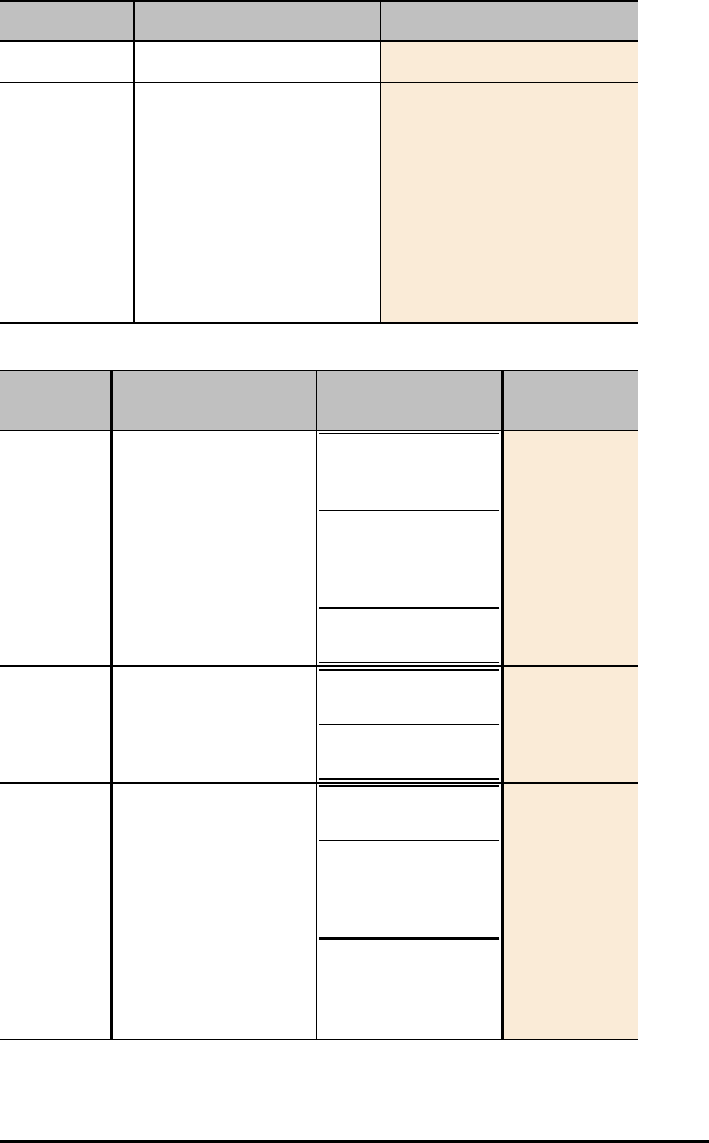
Component Desired Action Program Code
RV.COLOR.BLUE 150"
Gyroscope This component is used
internally by the FORWARD,
BACKWARD and ANGLE
commands. It can also be
used directly for machine-
level programming.
Send "SET
RV.ENCODERSGYRO 0"
Send "READ
RV.ENCODERSGYRO"
Get e
Send "READ RV.GYRO"
Get g
What are the full syntax options for the each of the Rover on-board components
Componen
t
Desired Action Desired Action Program Code
2 Motors
with
encoders
RV FORWARD
RV BACKWARD
Advanced:
SET RV.MOTORS <left
speed> <right speed>
READ
RV.ENCODERSGYRO
Drive in a straight
line for a fixed
distance/time
Drive/draw in a
specific shape (circle,
square, etc.) or
function
Drive to a specific
coordinate
For all Rover
Code Samples
and Test
Programs go to:
education.ti.co
m
Ultrasonic
Ranger
READ RV.RANGER Drive until an
obstacle is detected
Collect position
versus time data
Color
Sensor
READ RV.COLORINPUT
READ
RV.COLORINPUT.RED
READ
RV.COLORINPUT.GREE
N
READ
RV.COLORINPUT.BLUE
READ
RV.COLORINPUT.GRAY
Follow a line that is
on the floor
Speed up when
green is detected,
slow down when red
is detected
Frequently Asked Questions 131

132 Frequently Asked Questions
Componen
t
Desired Action Desired Action Program Code
RGB light
indicator
SET RV.COLOR <r> <g>
b>
Indicate different
colors depending on
how close to an
object
Provides visual
feedback/confirmatio
n during activity
Gyroscope READ
RV.ENCODERSGYRO
READ RV.GYRO
Angular positioning

I/O Module Details
What are the capabilities of the TI-Innovator™ I/O Modules available from TI?
Component Capabilities Details
Servo Motor 360 degree, continuous
rotation servo motor.
Can control direction and
speed. Should only be
connected to the OUT 3 port
and requires external power.
Vibration
motor
Coin type motor that
vibrates.
Can control the intensity of
the vibrations.
Light sensor Sensor that detects the
light intensity of the
environment.
Can detect ambient light
brightness. Value is scaled
from 0 (darkness) to 100
(bright sunlight).
White LED Light-emitting diode that
emits white light.
Can set LED on or off, set LED
to blink and determine
frequency and duration.
Ultrasonic
Ranger
Measures distance from
the module in centimeters
Can measure distance from
1cm to 4 meters
What are some examples of using the TI-Innovator™ I/O Modules available from TI?
Component Desired Action Program Code (TI CE
Graphing Calculator)
Servo Motor Rotate the shaft of the Servo
Motor connected to OUT 3
counter clockwise by 90°
Send("CONNECT
SERVO 1 TO OUT 3")
Send("SET SERVO 1
TO -90")
Vibration
motor
Turn on the Vibration Motor
connected to OUT 1
Send("CONNECT
VIB.MOTOR 1 TO OUT
1)
Send("SET
VIB.MOTOR 1 TO
ON")
Light sensor Read and display ambient
light level from the sensor
connected to IN 2
Send("CONNECT
LIGHTLEVEL 1 TO
IN2")
Send("READ
LIGHTLEVEL 1")
Get(L):Disp(L)
Frequently Asked Questions 133

134 Frequently Asked Questions
Component Desired Action Program Code (TI CE
Graphing Calculator)
White LED Turn on the White LED
module connected to OUT 1
Send("CONNECT LED
1 TO OUT 1")
Send("SET LED 1
ON")
Ultrasonic
Ranger
Read and display measured
distance from the ranger
connected to IN 2
Send("CONNECT
RANGER 1 TO IN2")
Send("READ RANGER
1")
Get(R):Disp (R)
What are the full syntax options for the each of the TI-Innovator™ I/O Modules
available from TI?
Compone
nt
Command Syntax Desired Action Code Samples
Servo
Motor
Send("SET SERVO n [TO]
[CW/CCW] speed [[TIME]
seconds] -- speed from -100
to 100, CW/CCW
(Clockwise/Counterclockwi
se) optional, if speed <0,
CCW, else CW unless
CW/CCW keyword is
specified, TIME optional, in
seconds, default=1 second
(for continuous servo
operation)
(CW/CCW required if
TIME/seconds NOT
specified.)
Configure the
program to use
SERVO on port
OUT 3
Send
("CONNECT
SERVO 1
TO OUT
3")
set SERVO to
turn
Counterclockwis
e (CCW) at full
(100%) speed
for 2 seconds
Send("SET
SERVO 1
CCW 100
2")
set SERVO to
turn Clockwise
(CW) at half
(50%) speed for
1 second
(default time if
not specified)
Send("SET
SERVO 1
CW 50")
Turn SERVO Off Send("SET
SERVO 1
ZERO")
or
Send("SET
SERVO 1
STOP")

Compone
nt
Command Syntax Desired Action Code Samples
Set SERVO to
move to -90
degree position
(CCW)
Send("SET
SERVO 1
TO -90")
or
Equivalent
code using a
variable with
eval():
angdeg:=-90
Send
("CONNECT
SERVO 1
TO OUT
3")
Send("SET
SERVO 1
TO eval
(angdeg)
")
Vibration
motor
Send("SET VIB.MOTOR 1
TO pwm") - pwm from 0 to
255
Configure the
program to use
ANALOG.OUT
on port OUT 2
Send
("CONNECT
VIB.MOTOR
1 TO OUT
2")
Turn OFF
vibration motor
Send("SET
VIB.MOTOR
1 TO 0")
Turn ON
vibration motor
at full power
Send("SET
VIB.MOTOR
1 TO
255")
Turn ON
vibration motor
at half power
Send("SET
VIB.MOTOR
1 TO
128")
Light
sensor
Send("READ LIGHTLEVEL
n")
Configure the
program to use
LIGHTLEVEL on
port IN 1
Send
("CONNECT
LIGHTLEVE
L 1 TO IN
1")
Frequently Asked Questions 135

136 Frequently Asked Questions
Compone
nt
Command Syntax Desired Action Code Samples
Read the light
sensor
Send
("READ
LIGHTLEVE
L 1")
Get(L)
White LED Send("SET LED 1 [TO]
ON/OFF [[BLINK|TOGGLE]
frequency] [[TIME] seconds]
")
Configure the
program to use
LED on port
OUT 1
Send
("CONNECT
LED 1 TO
OUT 1")
Turn LED ON Send("SET
LED 1
ON")
Turn LED OFF Send("SET
LED 1
OFF")
Turn external
LED ON for 5
seconds
Send("SET
LED 1 TO
ON TIME
5") --
Turn external
LED ON and
blink it at 2 Hz
(2 times a
second) for 5
seconds
Send("SET
LED 1 TO
ON BLINK
2 TIME
5")
Ultrasonic
Ranger
Send("READ RANGER n")
Get(R):Disp R
Configure the
program to use
RANGER on port
IN 1
Send
("CONNECT
RANGER 1
TO IN 1")
Read the
Ultrasonic
Ranger
Send
("READ
RANGER
1") Get
(R)
What other I/O Modules could work with the TI-Innovator™ Hub?
The items contained in the TI-Innovator™ kits have all been verified to be fully
compatible with the TI-Innovator™ Technology. The sketch of the TI-Innovator™ Hub
can support other modules that are compatible with the universal 4-pin connector that

is used for the input and output ports. Supported commands and potential modules are
listed below. If there are specific components you think would be valuable for
classroom activities, please contact TI-Cares and provide your feedback.
Example Module Component(s) Command/Sketch Object
Barometer Sensor BAROMETER
Button, Magnetic Switch BUTTON
3-Axis Digital Compass COMPASS
Fan DCMOTOR
Temperature & Humidity Sensor DHT
Single or variable color LEDs LED
Light sensor LIGHTLEVEL
Sound Sensor, Loudness Sensor LOUDNESS
Moisture Sensor MOISTURE
Collision Sensor, PIR Motion Sensor MOTION
Slide Potentiometer, Rotary Angle
Sensor
POTENTIOMETER
Electromagnet, Relay RELAY
Servo Motor SERVO
Buzzer, speaker SPEAKER
Switch SWITCH
Temperature Sensor TEMPERATURE
Frequently Asked Questions 137
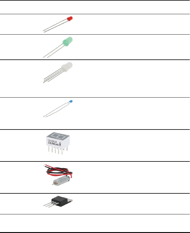
138 Frequently Asked Questions
Breadboard Components Details
What are the capabilities of the components in the TI-Innovator™ Breadboard Pack?
There are two types of components in the TI-Innovator™ Breadboard pack.
-Addressable components, such as LEDs and sensors, that responds to TI-
Innovator™ Hub commands.
-Passive components, such as resistors, capacitors, and manual switches that
are not directly addressable by the TI-Innovator™ Hub but are required in many
breadboard projects.
Addressable Components
Component Image Used with
pins
Description
Red LEDs BB 1-10 Light-emitting diode that
emits light when current
passes through it.
Green LEDs BB 1-10 Light-emitting diode that
emits light when current
passes through it.
RGB (Red-
Green-Blue)
LEDs
BB 8-10 Light-emitting diode
with independently
adjustable red, green
and blue elements. Can
produce a wide variety
of colors.
Thermistor BB 5,6,7
(analog
input
required)
Resistor whose
resistance changes based
on temperature. Used
for measurement and
control.
7-segment
Display
BB 1-10 Array of LEDs arranged to
display numbers and
some alphabetic
characters. Also has an
LED for a decimal point.
Small DC
Motor
BB 1-10
(uses digital
to generate
software
PWM)
Motor that converts
direct current electrical
power into mechanical
power.
TTL Power
MOSFET
BB 1-10 Transistorused for
amplifying or switching
electronicsignals.

TI Analog
Temperature
Sensor
BB 5,6,7
(analog
input
required)
Sensor that reports a
voltage proportional to
the ambient
temperature within a
range of −55°C to 130°C.
Visible Light
Sensor
BB 5,6,7
(analog
input
required)
Sensor that reports the
level of ambient light.
Infrared
Transmitter
LTE-302,
yellow dot
BB 1-10
(digital
output)
Side emitting Infrared
LED, designed to be
paired with the LTR-301
Photo-Transistor.
Infrared
Receiver
LTR-301,
red dot
BB 1-10
(digital
input)
Side sensing Infrared
photo transistor,
designed to be paired
with the LTE-302
Infrared Emitter.
See also: TI-Innovator™ Hub Ports and Breadboard Usable Pins
Frequently Asked Questions 139
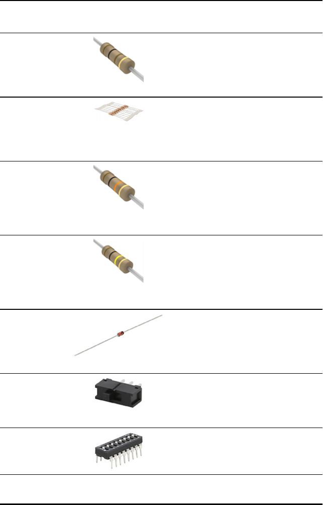
140 Frequently Asked Questions
Passive Components
Component Image Used
with
pins
Description
Resistor 100 Ohm
(10)
N/A Resistor that provides
100 Ohms of
resistance in a
circuit. Color Code
Value: brown, black,
brown. (10X10 = 100)
Resistor 1K Ohm
(10)
N/A Resistor that provides
1K Ohms of
resistance in a
circuit. Color Code
Value: brown, black,
red (10X100 = 1,000)
Resistor 10K Ohm
(10)
N/A Resistor that provides
10K Ohms of
resistance in a
circuit. Color Code
Value: brown, black,
orange (10X1,000 =
10,000)
Resistor 100K
Ohm (10)
N/A Resister that provides
100K Ohms of
resistance in a
circuit. Color Code
Value: brown, black,
yellow (10X10,000 =
100,000)
Diode BB 1-10 Allows an electric
current to pass in
one direction, while
blocking current in
the opposite
direction.
SPDT Slide Switch BB 1-10 Single pole, double
throw switch. Slide
the switch knob back
and forth to open
and close contacts.
8 Position DIP
Switch
BB 1-10
(digital
input)
Set of 8 slide
switches used to
customize the
behavior of the
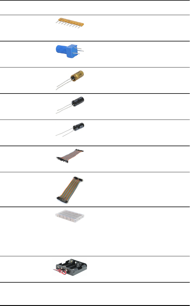
circuit components
for specific situations.
8 100 Ohm
resistor SIP
Package
N/A 8 100 Ohm resistor
SIP package for use
with 8 Position DIP
Switch.
Potentiometer
with Knob
BB 5,6,7 Variable resistor with
knob used to change
the resistance in a
circuit..
Capacitor 100µF N/A Capacitor that
temporarily stores an
electric charge of up
to 100µF.
Capacitor 10µF N/A Capacitor that
temporarily stores an
electric charge of up
to 10µF.
Capacitor 1µF N/A Capacitor that
temporarily stores an
electric charge of up
to 1µF.
40-Pack
male/male
Breadboard
Jumper Cables
N/A Male to Male jumper
cables for connecting
components on the
breadboard.
10-Pack
male/female
Breadboard
Jumper Cables
N/A Male to female
jumper cables for
connecting
components on the
breadboard.
Breadboard N/A Platform for
connecting the
electronic
components of a
project by inserting
component leads and
jumper cables into
pins.
4-AA Battery
Holder
N/A 4-AA battery holder
with tined solid leads
for easy breadboard
insertion.
Frequently Asked Questions 141

General Information
Texas Instruments Support and Service
General Information: North and South America
Home Page: education.ti.com
KnowledgeBase and e-mail inquiries: education.ti.com/support
Phone: (800) TI-CARES / (800) 842-2737
For North and South America and U.S.
Territories
International contact information: education.ti.com/support/worldwide
For Technical Support
Knowledge Base and support by e-mail: education.ti.com/support or
ti-cares@ti.com
Phone: (866) 846-2844
For Product (Hardware) Service
Customers in the U.S., Canada, Mexico, and U.S. territories: Always contact Texas
Instruments Customer Support before returning a product for service.
For All Other Countries:
For general information
For more information about TI products and services, contact TI by e-mail or visit the
TIInternet address.
E-mail inquiries: ti-cares@ti.com
Home Page: education.ti.com
Service and Warranty Information
For information about the length and terms of the warranty or about product service,
refer to the warranty statement enclosed with this product or contact your local Texas
Instruments retailer/distributor.
General Information 142
