JBL VERTEC White Paper
User Manual: JBL JBL - Manuals+
Open the PDF directly: View PDF ![]() .
.
Page Count: 16

1
White Paper
JBL’s Vertical Technology™:
Achieving Optimum Line Array Performance Through
Predictive Analysis, Unique Acoustic Elements and a
Dedicated Loudspeaker System
October, 2003 – Audio Engineering Society Convention by John Eargle, David Scheirman and Mark Ureda
1. INTRODUCTION:
This White Paper introduces the princi-
ples of JBL’s Vertical Technology™. This
technology comprises a predictive tool,
unique electroacoustical elements, and a
family of multiway loudspeaker systems.
These form JBL’s VERTEC™ system, a
next-generation line array product rst
embodied in the Model VT4889 full-
range system. VERTEC users have access
to a design program enabling systems
to be arrayed a priori with the assurance
that array performance will accurately
meet the program’s response estima-
tions. In this paper we will:
A. Cover the basics of line array tech-
nology from its beginnings to the
present;
B. Dispel much of the mystery sur-
rounding line array technology;
C. Outline in detail the development of
a full-range loudspeaker system and
the computer software that optimizes
arrays made up of these systems to
produce a desired directional re-
sponse.
2. WHAT IS A LINE ARRAY?
Line array loudspeakers date from the
early days of acoustical research when
it was observed that a simple vertical
array of radiators produced increased
directivity in the vertical plane.(1) Early
commercial development is shown in
Figures 1 through 3.
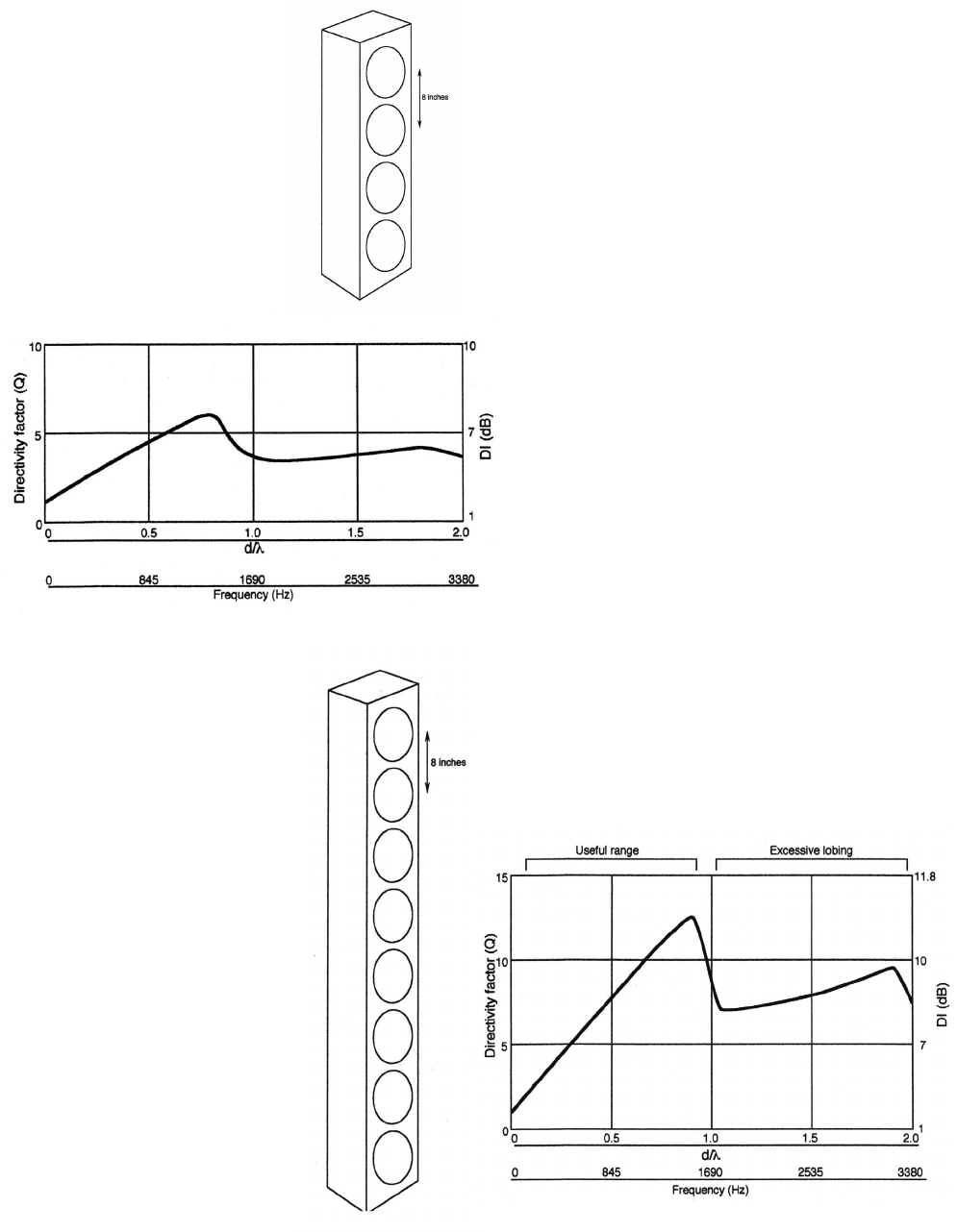
Figure 1A shows an array of four small
drivers with a 200-mm (8-in.) center-to-
center distance. Figure 1B shows the Q
and DI (Directivity Index) of this short
array. The DI increases up to that fre-
quency where the response maintains a
degree of useful directivity, but with the
addition of mild off-axis lobes. The limit-
ing frequency is where the inter-driver
spacing is equal to the signal wave-
length:
flimiting = (1130 x 12)/8 = 1690 Hz.
Horizontal directivity of the array is the
same as that for a single driver. In addi-
tion to the height of the array, the center-
to-center spacing of acoustic sources
directly inuences directionality of even
the simplest line arrays.
2
3
array at higher frequencies enabled it to
hold its consistent coverage pattern with
increasing frequency. Klepper & Steele
(1963) devised a unique, low-cost way to
accomplish the progressive truncation of
the array length with increasing frequen-
cy through a gradual high frequency
rolloff of the outer elements.(2) They
employed carefully tapered wedges of
berglass in front of the transducers to
act as progressive acoustical low-pass
lters.
Meanwhile, Hilliard (1970) was ad-
dressing aspects of motion picture
sound with vertical columns of LF driv-
ers. As his analysis tool he constructed
arrays of small drivers and then scaled
the results to give the response for 15-
inch driver arrays.(3)
Overall, line arrays of the sort discussed
here were excellent for speech or solo
vocal purposes in moderate size rooms.
Array theory was rarely if ever applied to
high level music reinforcement, primar-
ily because the available systems were
physically small. Most commercial ar-
rays, or “sound columns,” made use of
8-inch or smaller cone drivers and were
clearly limited in their output capability.
If we want increased
vertical directivity we
can use more driv-
ers. Figure 2A and B
show the effect of an
8-driver array with the
same 200-mm (8-in)
spacing. The array
achieves very high
directivity in the range
up to the limiting
frequency of 1690 Hz;
however, above that
frequency the off-axis
lobing becomes very
signicant, and any
directivity advantage
drops off quickly.
It was soon dis-
covered that reduc-
ing the length of the
Figure 2A. An 8-element line array
Figure 1. A 4-element
line array (A); direc-
tivity of 4-element
array (B).
Figure 2B. Directivity of 8-element array (B).
2
3
2.1 JBL’S EARLY LINE ARRAY
SYSTEMS:
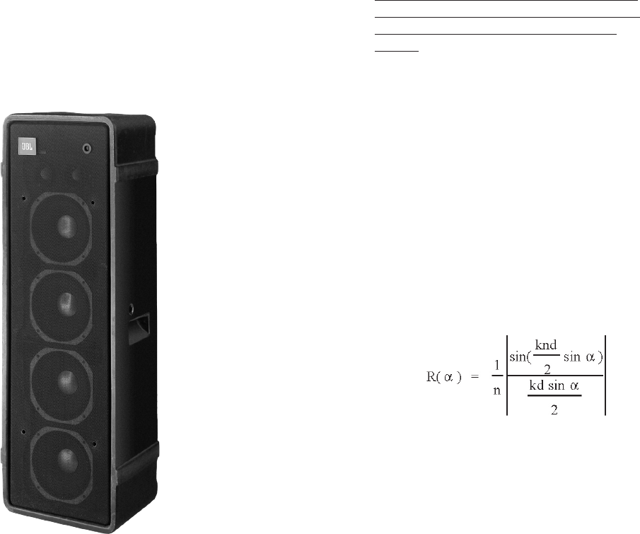
JBL developed a number of line array
systems during the 1970s. The 4682,
shown in Figure 3, is typical. Full power
capability of the four 10” drivers, ar-
ranged in a vertical line format, was
maintained at frequencies up to 2 kHz.
At one-tenth its rated power, this system
was capable of producing 96 dB SPL at
a distance of 15.25 meters (50 ft).
JBL’s early line array system products
were based on the foundations of acous-
tical knowledge gained from decades
of previous experimentation by sound
reinforcement industry pioneers. This
experience was applied for the benet
of professional users, and it led to the
creation of new high-powered trans-
ducers able to take portable sound
reinforcement systems to a new level of
performance. Astute observers will be
able to draw links be-
tween the Model 4682
system shown here
and innovative tour
sound products that
emerged in the same
time period.
At the core of JBL’s Ver-
tical Technology pro-
gram is the recognition
that the same line array
physics established by
industry pioneers, and
evidenced in products
like the Model 4682 line
array system nearly
30 years ago, are ap-
plicable to modern,
modular array elements
and are thus scalable
for use in larger-format
systems.
3. BASIC LINE ARRAY THEORY:
3.1 THE SUMMATION MODEL:
The arrays discussed so far can be
easily analyzed, and their directional
response can be determined using a
discrete, or summation, model.
In this analytic approach, the array is
broken down into component elements
whose outputs are summed to produce
the array’s net response. The summation
is taken to arrive at the array’s response
as it would be observed in the far eld
— the region in which inverse square
law holds, with its characteristic falloff of
6 dB per doubling of distance.
The far eld begins at a distance that is
proportional to the product of frequency
and the square of the effective array
length. At closer distances, we are in the
near eld, where the falloff with distance
from a simple array does not follow in-
verse square law. Because it is an inter-
ference eld, the changes in level with
distance and/or angular displacement can
be abrupt and unpredictable in the near
eld.
If we use the summation model and
we assume that all elements are driven
by the same signal, that the output
amplitude and phase relationships are
identical for all elements, and that the
elements are all omnidirectional, then
the directional response can be given by
the following equation:
(1)
where n is the number of elements in
the array and d is the spacing between
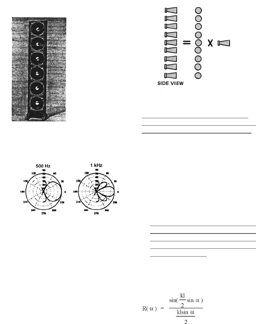
them.(4,5) Let’s use this relationship to
determine the response of Hilliard’s
vertical array of 127 mm (5-in) drivers as
shown in Figure 4A.
Figure 3. The JBL Model 4682
line array from the 1970s.
4
5
Figure 4A. Hilliard’s 6-element line array of
5-inch drivers
Here, the number
of elements is 6
and the spacing
between them is
5 inches. Using
the summation
model equation
we arrive at the
polars shown at
4B for 500 Hz
and 1 kHz. The
500 Hz polar
shows a single,
broad major lobe.
This demon-
strates good directivity at this frequency.
The 1 kHz polar shows the formation
of a narrower primary lobe with smaller
secondary (off-axis) lobes.
Figure 4B. Hilliard’s polar response at 500 Hz
and 1 kHz (B).
3.2 THE PRODUCT THEOREM
— PERFORMANCE AT HIGHER
FREQUENCIES:
The product theorem states that the
response of an array can be obtained
by multiplying its directional response
by the response of a single element
in the array.(6) This denition is shown
graphically in Figure 5. The rst prod-
uct theorem allows us to make a better
approximation of an array’s directivity
by multiplying the known directional
characteristics of a non-simple source
by the directional characteristics of an
array of simple sources.
Figure 5. Graphical representation of the prod-
uct theorem.
Thus, if the individual driver beams at
high frequencies, the net array response
will be impacted by this same beaming.
This will be superimposed on the array
response as determined by Equation 1.
4. LINE ARRAY THEORY USING
THE INTEGRATION MODEL:
As long as we compose our line array
of individual, discrete elements then
equation (1) will give us the answers we
need. However, it is important to note:
If we design new loudspeaker compo-
nents that can be combined to form a
continuous “ribbon” or line from top to
bottom, we need a new mathematical
model to describe it.
Without burdening the reader with the
rigors of the math involved, we’ll go
directly to the governing equation:
(kl/2 = pl/l, where l is the array length) (2)
This equation enables us to determine
the response of the continuous array in
the far eld.
4
5
Remember, the far eld begins at that
distance where we rst notice that
the fall-off in response follows inverse
square law, diminishing 6 dB with
each doubling of distance.
4.1 DECIBELS VERSUS DISTANCE
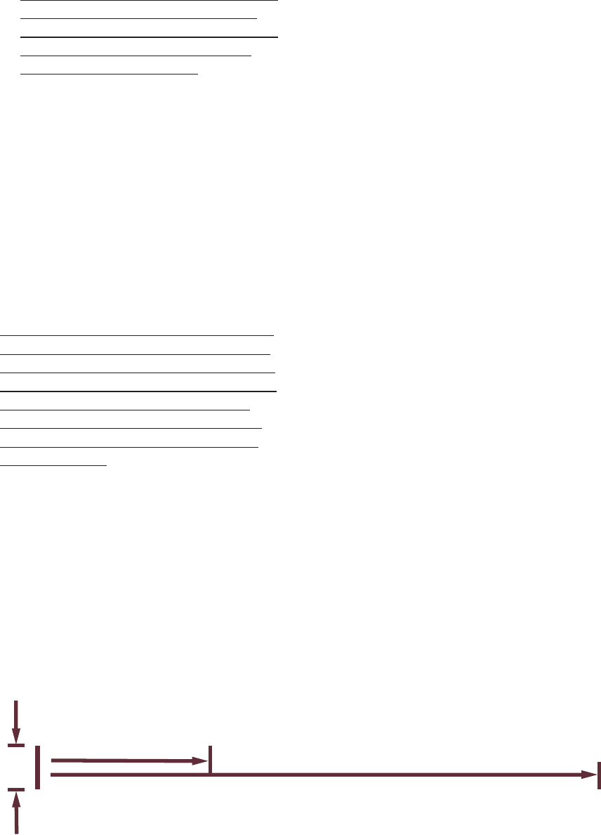
Figure 6 shows a continuous array 3
meters (10 feet) high, and we have indi-
cated the distances at which the far eld
begins at 1 kHz and 10 kHz. Note that at
1 kHz the far eld begins at 13 meters
(43 feet), while at 10 kHz it begins at
130 meters (430 feet).
At high frequencies, the more disparate
sources do not contribute coherently to
the on-axis sources until a considerable
distance from the array. This means that
high frequencies will appear to have
a farther "reach" than low frequencies
when we listen to the array on-axis at
large distances.
This comes as a simple consequence of ba-
sic physics and is not a result of any unique
or advanced proprietary engineering.
When we consider the -6-dB beam-
width in the far eld at high frequencies
we can observe another phenomenon.
In the example of Figure 6, the -6-dB
beamwidth is only 0.8 degrees at 10
kHz. It is clear that only a small frac-
tion of the audience will be in the zone
where such performance could be ap-
preciated.
This phenomenon has been presented
and discussed in prior literature. Not
so often discussed is the frequency-
dependent nature of this effect and the
varying coverage patterns that result. If
we are to optimize the performance of a
particular array used to cover a specic
audience area, we must take all aspects
of line array performance into account
when constructing the array.
Figure 6: A far-eld example. For a 3-meter array, the far eld begins at 13 meters (43’) for 1 kHz and
at 130 meters (430’) for 10 kHz.
6
7
5. NOT ALL ARRAYS ARE
STRAIGHT:
If a line array is to be useful in large-
scale sound reinforcement it must be
capable of excellent coverage for all
patrons. This normally requires that
the vertical line array be articulated, or
curved in the vertical plane.
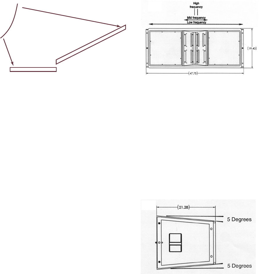
Figure 7. A curved array may be required for
near and far coverage.
A typical coverage situation is shown
in Figure 7. We can see intuitively that
the far-throw coverage can be met by a
relatively straight section of the array el-
ements, while the near throw coverage
will require some degree of curvature in
order to provide uniformity of coverage
over a wider vertical angle.
The VERTEC solution to this design prob-
lem has been met through the design
of a family of unique 3-way line array
elements along with a Windows/Excel
PC computer program, the JBL VERTEC
Line Array Calculator. This software tool
is capable of estimating the response of
an arbitrarily articulated vertical array
of such elements.
Using this program a JBL VERTEC sys-
tem user can enter the vertical cross-
section view of a performance space.
The designer can then enter into the
program various articulated vertical ar-
rays and observe the net response on
the seating areas. But rst let’s look at
the new loudspeaker design required to
integrate classical line array acoustics
and the predictive software program
into a useful, eld-oriented sound rein-
forcement solution.
6. DETAILS OF THE JBL VT4889
SYSTEM:
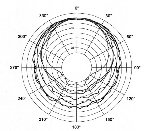
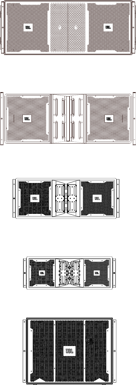
Figure 8A shows a front view of the 3-
way 4889 system. The inner HF section
consists of 3 in-line diffraction slots,
each fed by the newly-designed 2435
compression driver. These in-line slots
run from top to bottom and enable verti-
cally stacked 4889 systems to provide a
virtually continuous HF radiating seg-
ment from enclosure to adjacent enclo-
sure.
A side view of the enclosure is shown
at B, indicating the vertical relief angles
on top and bottom sides that allow for
articulation of adjacent enclosures.
Figure 8B. Side view of the JBL VT4889
system.
6
7
Each frequency section should form a
continuous virtual ribbon relative to its
operating frequency range for the array
to function properly. Gaps between cabi-
nets should be minimized and remain
constant for all splay angles between
cabinets to prevent destructive interfer-
ence at high frequencies.
Two MF sections ank the triple HF dif-
fraction slot. Each of these contains two
200 mm (8-in) neodymium drivers with
dual voice coils, working into compres-
sion slots located along the waveguide
expansion of the HF section. On the out-
side are a pair of 380 mm (15-in) drivers.
Crossover frequencies are roughly 200
Hz and 1.1 kHz with specic overlapping
characteristics, so both LF and MF sys-
tems are effectively continuous radiators
over their ranges of wavelength opera-
tion, resulting in a nested array of LF,
MF and HF sections, as indicated at 8A.
Precise control of HF radiation in the
proprietary waveguide is enabled by
geometrical tapering of the path from
each HF driver to the diffraction slot to
ensure that there is no vertical beaming
over the HF passband of the system.
Because of the close nesting of HF and
MF elements, advanced acoustical and
mechanical engineering was required.
This included the waveguide boundaries
that load the HF drivers and the com-
pression loaded slots through which the
MF drivers radiate.
A new Radiation Boundary Integrator
(RBI™) was devised to allow the exit of
HF acoustical energy past a boundary
surface which is integral to MF radiation,
making it virtually “invisible” to MF power
radiation. This results in a smoother cov-
erage pattern while reducing intermodu-
lation distortion.
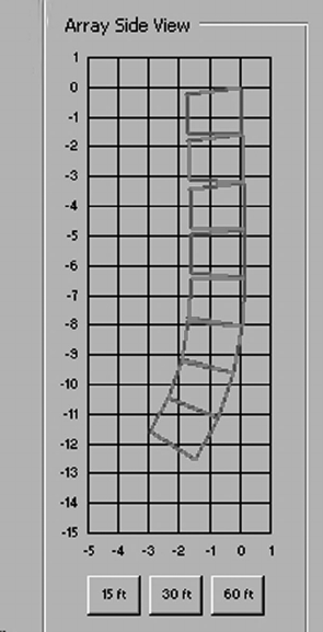
Figure 9 shows the horizontal polars for
the VT4889 system. These indicate the
effective horizontal coverage of a typical
vertical array of the elements, and that
response is largely independent of the
vertical articulation of elements.
Figure 9. Horizontal polar response of a single
JBL VT4889 system.
6.1 MECHANICAL DETAILS OF
THE VT4889 SYSTEM:
We have seen in Section 4 that a con-
tinuous ribbon of sound with no gaps in
the radiating surface is preferable, and
in Section 5 we noted that arrays may
need to be curved to adequately cover
typical audience areas. The VERTEC sys-
tem enclosures have been designed to
take maximum advantage of these two
acoustical requirements.
Measuring only 1213 mm x 489 mm x
546 mm (47.75” W x 19.25” H x 21.4”
D), each enclosure includes all required
hanging and rigging hardware ttings to
couple one box to another.
To make eld handling easier and to en-
able systems users to create very large
arrays, the individual box weight of the
full-size VT4889 is only 72 kg (159 lb.),
8
9
despite a transducer complement that
includes (2) 600-watt LF drivers, (4)
400-watt MF drivers, and (3) 100-watt
large format HF compression drivers.
Due to the low individual weight of each
array element, up to 18 VT4889 sys-
tems can be suspended from a single
VT4889-AF hanging Array Frame, with
a 7:1 design factor. The enclosure’s
compact size allows it to be stacked on-
end, two-high in typical transport truck
bodies with interior ceiling heights as
low as 2438 mm (96 in).
7. CASE STUDIES:
With JBL’s Vertical Technology, the
horizontal coverage of an array is xed
(nominally 90°) and thus becomes a
“constant” baseline on which the VERTEC
system engineer can build a well
planned event or venue sound design.
The primary tool is the software pre-
diction program which enables the user
to preview the expected results from the
number of enclosures and their hinge-
bar (vertical displacement) angles to
achieve optimum coverage of the audi-
ence seating areas.
The VERTEC Line Array Calculator, a
software tool based on Microsoft Excel,
allows the design engineer to select
the number of array elements and
individually adjust the splay angles
between adjacent elements. The de-
signer can specify up to three seating
planes and determine the front-to-back
distances as well as the slope of each
plane, all relative to the location of the
line array. The program then asks the
user to select a frequency (one-third oc-
tave centers from 100 Hz to 20 kHz).
When a frequency is selected the pro-
gram calculates the vertical polar plot of
the line array on 1-degree increments
and indicates the front-to-back center-
line coverage in dB on each of the three
seating planes.
Through an intuitive process of entering,
observing, and changing the angular re-
lationships between adjacent elements,
the designer can fairly rapidly arrive at
a target directional function for any ar-
ray of multiple enclosures. Additionally,
useful mechanical information such as
overall array weight, sizing and such is
available to the system engineer.
Figures 10 through 12 show typical data
produced by the design program, com-
pared to actual eld measurements of
the same array that is depicted in the
software.
Note that all eld measurements were
taken in a half-space groundplane
environment, with the measurement
microphone positioned at a distance of
20 meters.
Figure 10A. Calculations vs. measurements.
An 8-element array (A).
8
9
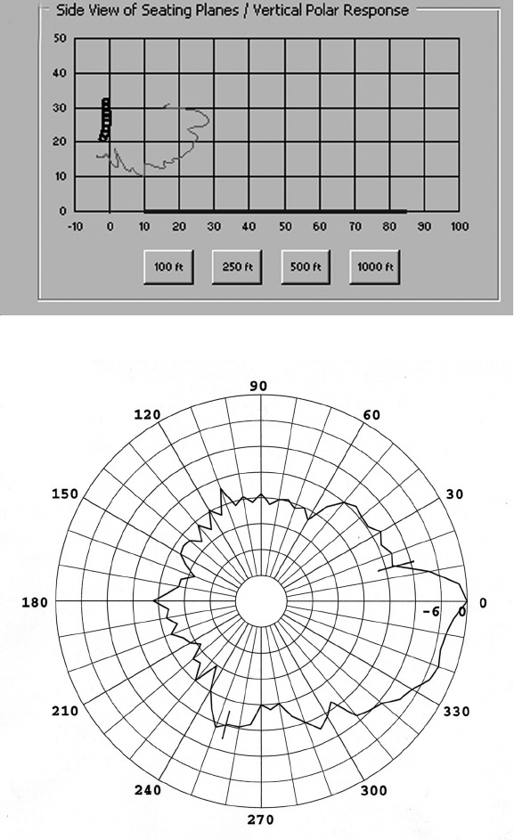
It should be pointed out that the angular range of the computed polar plot consists only
of the forward 120 degrees of the system’s response; this range is marked off in the
measured polar plots. It is clear that the program’s estimates of polar response very
closely match the measured data, consistent with the 5-degree resolution of the mea-
surements.
An 8-element array is shown at A. The computed polar plot at 250 Hz is shown at B,
along with the actual, measured 20-meter polar response at C.
Figures 10B & C. Calculations vs. measurements. Computed polar response at 250 Hz (B);
measured polar response at 250 Hz (at 20 meters) (C).
10
11
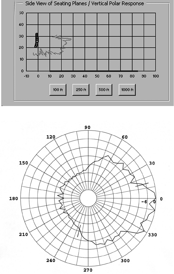
Figure 11 shows corresponding computed and measured data at 1 kHz. The polar data
produced by the design program are computed on one-degree increments, whereas
the measured polar data are taken every 5 degrees.
Figure 11. Calculations vs. measurements.
Computed polar response at 1 kHz (A); measured polar response at 1 kHz
(at 20 meters) (B).
10
11
Figure 12. Calculations vs. measurements.
Computed polar response at 4 kHz (A); measured polar response at 4
kHz (at 20 meters) (B).
Figures 12A and 12B show corresponding data at 4 kHz.
12
13
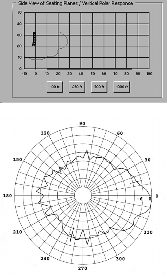
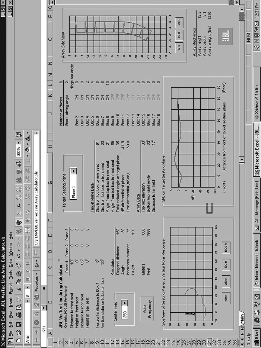
Figure 13. JBL VerTec line array calculator: Full computer display.
12
13
In order to give the reader an idea of the
full scope of the VERTEC Line Array Cal-
culator design program, Figure 13 illus-
trates a full-screen view of the program,
showing mechanical details of the array,
effective polar data, and uniformity of
coverage on any selected seating plane.
Note an array of eight (8) full-size
VT4889 enclosures has been selected,
with an array aiming angle (‘Box 1’) of
2 degrees downtilt, with individual box
aiming angles set at 0, 0, 2, 4, 6, 8 and
10. The graphic gure at the lower cen-
ter of the display shows the predicted
sound pressure level of the array at 250
Hz, from the rst to last seating rows.
Array design, splay angles and perfor-
mance results will vary when the mid-
size VT4888 or compact VT4887 multi-
way line array element are used.
CONCLUSIONS
The introduction of JBL’s Vertical Tech-
nology has taken the mystery and
mythology out of line arrays. It has been
shown that classical array acoustics
which were used to create rst-gen-
eration line array systems more than
50 years ago still hold true today, and
that the same mathematical concepts
explained by classical acoustical re-
searchers like Beranek, Olson and Hill-
iard can be scaled up to create higher-
powered line array systems capable of
serving the sound reinforcement needs
for both voice and music in even the
largest of performance venues.
JBL’s VERTEC line array systems, with
their unique suspension hardware sys-
tem, provide a continuous bafe surface
and can be congured into straight-line
arrays, uniformly and non-uniformly
curved arc arrays, progressive spiral,
and J-form arrays. They are representa-
tive of the dramatic evolution of the origi-
nal compact ‘speaker column’ that was
rst explored by such early practitioners.
Such exible, full-bandwidth arrays offer
a powerful new set of tools for the sound
reinforcement industry.(7)
One of the most signicant things to
comprehend is that, regardless of origin
or manufacturer, when modular ele-
ments are combined into a line array, the
observer should not, and indeed cannot,
expect the axial directivity of the larger
array to behave as if it were simply a
composite stack of linear soundpaths,
or ‘laser-like’ box angles. The observer
will come to understand that the array’s
performance should be evaluated holisti-
cally, rather than from the point of view
of discrete array elements.
In effect, the performance of a modular
line array, regardless of element size
and the number included in the array,
will be inuenced by the acoustical
characteristics and capabilities of each
individual enclosure. Assuming a viable
design for the individual enclosure, suc-
cessful eld deployments of line array
systems can now be realized, ranging
in size from small to large systems for a
variety of venues and events.(8)
The expectations of audiences and
sound engineers alike have changed
greatly since the early days of acous-
tical research. New line array system
tools are now available to meet those
expectations of clear, articulate sound
with higher system output and greater
dynamic headroom potential. With the
application of JBL’s Vertical Technology,
the VERTEC system gives modern system
designers and operators that capability.
14
15
BIBLIOGRAPHY:
(1)Wolfe, I. & Malter, L. “Directional
Radiation of Sound,” J. Acoustical
Society of America, volume 2, num-
ber 2, p. 201 (1930).
(2)Klepper, C & Steele, D., “Constant
Directional Characteristics from a
Line Source Array,” J. Audio Engi-
neering Society, volume 11, number
3 (July 1963).
(3)Hilliard, J., “Unbafed Loudspeaker
Column Arrays,” J. Audio Engi-
neering Society, volume 18, number
6 (1970).
(4)Beranek, L., Acoustics, McGraw Hill,
New York (1954).
(5)Olson, H., Elements of Acoustical
Engineering, p. 25. D. Van Nostrand,
New York (1940).
(6)Kinsler, L. & Frey, A., Fundamentals
of Acoustics, John Wiley & Sons,
New York (1980).
(7) Engebretson, M. “Directional Radia-
tion Characteristics of Articulating
Line Array Loudspeaker Systems”,
presented at the 111th Convention of
the Audio Engineering Society, New
York, NY, December 2001.
(8) Scheirman, D. “Practical Consider-
ations for Field Deployment of Modu-
lar Line Array Systems”, presented
at the 21st International Conference
of the Audio Engineering Society, St.
Petersburg, Russia, June 2002.
14
15
VT4880
(Full-size arrayable subwoofer)
VT4889
(Full-size 3-way line array element)
VT4888
(Midsize 3-way line array element)
VT4887
(Compact bi-amplied 3-way
line array element)
VT4881
(Compact arrayable subwoofer)

16
Part # WPVERTEC 10/03
JBL Professional
8500 Balboa Blvd., P.O. Box 2200
Northridge, CA 91329 U.S.A.
