JBL Technote V1 N33
User Manual: JBL JBL - Manuals+
Open the PDF directly: View PDF ![]() .
.
Page Count: 8

1. Introduction:
JBL Professional introduced the
Differential
Drive
concept in the EON System in 1995 as a
means of attaining maximum system perform-
ance with minimum weight. Compared with tra-
ditional driver designs, JBL’s patented
Differential Drive makes use of a pair of in-line
voice coils in separate magnetic gaps instead
of a single voice coil-gap combination. This
permits a more effective use of available
space, and allows more efficient removal of
heat from the motor structure. Specifically, the
voice coils are reversely wound and are
immersed in magnetic fields of opposite polari-
ty. This ensures reduced magnetic leakage flux
and focuses more magnetic energy in the gaps
where it is needed. Both ferrite and neodymi-
um-iron-boron (NIB) magnets can be used,
depending on the relative importance of weight
in a given system design. When coupled with
the light weight and high energy density of NIB
magnets, Differential Drive transducers can be
constructed that are only about one-third the
weight of traditional designs of comparable
performance.
Differential Drive provides many design options
for the engineer. The size, impedance, and
spacing of the two voice coils can be inde-
pendently adjusted relative to each other to
attain a desired set of electromechanical per-
formance features. Independently of these, the
overall size and mass of a system can be
adjusted as required. JBL has been granted
numerous patents on multiple aspects of
Differential Drive dual-coil, dual gap designs.
We will compare the traditional approach with
Technical Note Volume 1, Number 33
Title: JBL's Differential Drive®Transducers
Differential Drive technology in detail.
2. Anatomy of a Differential Drive transducer:
The simplest way to understand Differential Drive is
to compare it directly with JBL’s traditional motor
structures. Figure 1 shows a section view of a tradi-
tional JBL magnet-voice coil assembly and a
Differential Drive system. As a starting point, let us
design the Differential Drive system so that its
parameters are identical to those of the traditional
motor structure, with the same electrical-to-mechani-
cal coupling and the same moving mass.
In the traditional design, magnetic flux density
B
crosses a gap in which a coil of wire of length
l
is
placed. The coil has an electrical resistance,
R
E
.
These quantities establish the value of
(Bl)2/R
E
,
which is the electromechanical coupling factor of the
driver.
Now we inspect the Differential Drive topology. In
this design there are two magnetic gaps that have
opposing flux fields, and each gap has a
B
field
equal to that of the traditional design. Two reversely-
wound coils are used, each using wire with one-half
the cross-section width as before. The coils are
scaled so that they are one-half the length of the
traditional coil. In addition, the masses of the two
thinner coils will equal that of the single traditional
coil.
Each of these thinner coils will then have a coupling
factor of
0.5(Bl)
2
/R
E
, or one-half that of the tradition-
al driver. Since there are two such voice coils, both
acting in the same direction, the total coupling factor
for the new motor structure will be identical to that of
the traditional design. This relationship is shown in
Figure 2.
1

Figure 1. Comparison of standard and Differential Drive technologies.
Figure 2. The equivalence of standard and Differential Drive technologies.
2
In redesigning the system as shown here we
have gained some significant design advan-
tages:
A. Better heat dissipation. The physical sep-
aration of the two coils can be adjusted for
optimum heat transfer from each coil to the
outer structure of the driver. In addition, the
total surface area of the two coils has doubled,
creating twice the heat radiation capability.
B. The new voice coil arrangement will have
less
effective inductance than the standard
one, since the reversely wound coils will have
negative mutual inductance between them.
This translates into a more uniform impedance
curve and extended output at higher
frequencies.
C. The compact nature of the Differential
Drive motor structure requires much less iron
in the magnetic return path. If NIB (neodymi-
um-iron-boron) magnet material is used, a
Differential Drive transducer can weigh as little
as
one-third
the equivalent traditional ferrite
design. This advantage shows up primarily in
overall system weight and ease of installation.
D. The structure is inherently shielded mag-
netically, especially at 90 degrees away from
the axis of the structure. The result is very little
stray magnetic field interference with CRT
video systems.
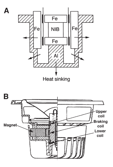
E. Nesting the small overall magnet struc-
ture in a large aluminum heat sink results in
efficient dissipation of heat from the coils, as
shown in Figure 3A. Aluminum, with its high
specific heat and low thermal resistance, is the
ideal material for this. The section view shown
at B illustrates the use of ferrite magnet materi-
al in the design of a Differential Drive transduc-
er which includes a braking coil, as discussed
in Section 5.
F. Design flexibility. The two voice coils may
be driven in electrical series or parallel,
depending on the system design impedance.
Typical applications call for a nominal 8-ohm
driver, with two 4-ohm coils operating in electri-
cal series.
G. Push-pull operation. In an analogy to
Class AB operation of a power amplifier, the
motion a Differential Drive system reduces
even-order distortion components, due to the
exact symmetry of the motor structure along its
operating axis.
3
Figure 3. Nesting of the dual coil structure in an aluminum heat sink (A); section view of a
ferrite-based Differential Drive transducer which includes a braking coil (B).
See Section 5 for a discussion of the braking coil.
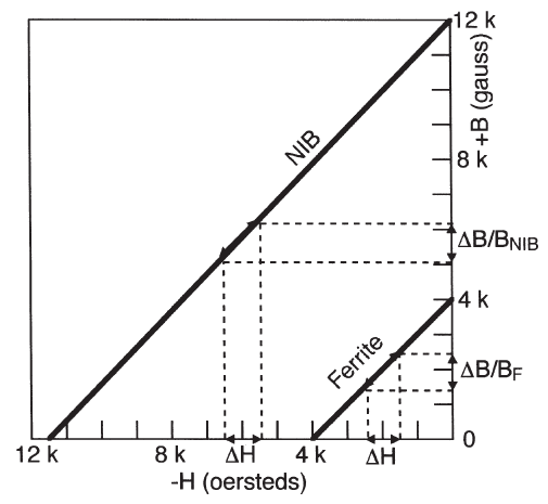
Figure 4. Flux modulation in ferrite and NIB magnet structures.
4
4. Performance of Typical Drivers:
The transducers in all of these curves are
mounted in a 280-liter (10 cu. ft.) sealed enclo-
sure. Low-frequency response and distortion
performance would be further enhanced in an
appropriate vented enclosure.
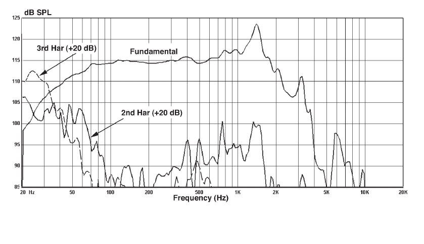
The model 2262H 300 mm (12-inch) Driver:
Figure 5 shows the second and third harmonic
distortion for the model 2262H LF driver oper-
ating with a power input equal to one-tenth (-10
dB) the transducer’s rated power of 700 watts.
The applied signal is 23.7 Vrms across a nomi-
nal 8-ohm load, corresponding to normal pro-
gram operation of the driver.
Note that the third harmonic distortion at 40 Hz
is no greater than 10% (where the distortion
and fundamental curves intersect). Over the
broad range from 100 Hz to 2500 Hz, second
and third harmonic distortion values are below
2% at 113 db SPL at 1 meter. This driver was
designed with the general characteristics of the
traditional 2206H in mind, and it can function
as either a LF horn driver or as a upper-bass,
lower MF direct radiator.
3. Transducer magnetic circuit linearity:
The neodymium magnet material used in most
Differential Drive transducers is much less
prone to flux modulation than ferrite materials.
As a result, the flux shorting ring, an essential
part of JBL's Symmetrical Field Geometry™, is
not usually necessary with neodymium-based
structures. Figure 4 shows the demagnetiza-
tion characteristics for typical NIB and ferrite
magnet materials. We can see that a typical
operating point for the neodymium magnet is
much higher along the B-axis than that of a fer-
rite magnet. Therefore, for a given change in
magnetizing force produced by signal current
in the voice coil, the resulting change in
induced flux
(
⌬
B/B
NIB
)
will be fairly small. By
contrast, the resulting change in induced flux
for the ferrite magnet will be ⌬
B/B
F
. Since
B
F
is
less than
B
NIB
, the total variation in induced flux
will be greater with the ferrite magnet. There is
about a three-to-one ratio between the amount
of flux modulation of the two magnet materials,
corresponding to an approximate 10 dB advan-
tage for neodymium over ferrite at any operat-
ing level.

5
Figure 5. Second and third harmonic distortion components, raised 20 dB
relative to the fundamental, in the 2262H driver at one-tenth rated power.
The model 2265H 380 mm (15-inch) Driver:
Figure 6 shows similar data for the model
2265H driver. Here, the second harmonic dis-
tortion is 10% at about 33 Hz, while the distor-
tion components in general are below 2% from
50 Hz to 2 kHz at approximately 114 dB SPL
at 1 meter.
Figure 6. Second and third harmonic distortion components raised 20 dB
relative to the fundamental, in the 2265H driver at one-tenth rated power.
6
5. The Dynamic Braking Coil:
The JBL LSR6300 Series studio monitors uti-
lize Differential Drive with an added feature.
During high drive conditions at low frequencies
there is a tendency for cone excursions to
approach and even exceed normal limits of lin-
ear travel. When this occurs there will be a rise
in distortion due to two factors: mechanical
nonlinearity of the suspension and loss of
Bl
product as the voice coils move out of the lin-
ear gap range.
Earlier solutions to this problem involve so-
called
progressive
inner suspensions whose
mechanical stress-strain curves have been tai-
lored to compensate – and cancel – the rise in
distortion. With Differential Drive systems we
have an additional tool here: the dynamic brak-
ing coil.
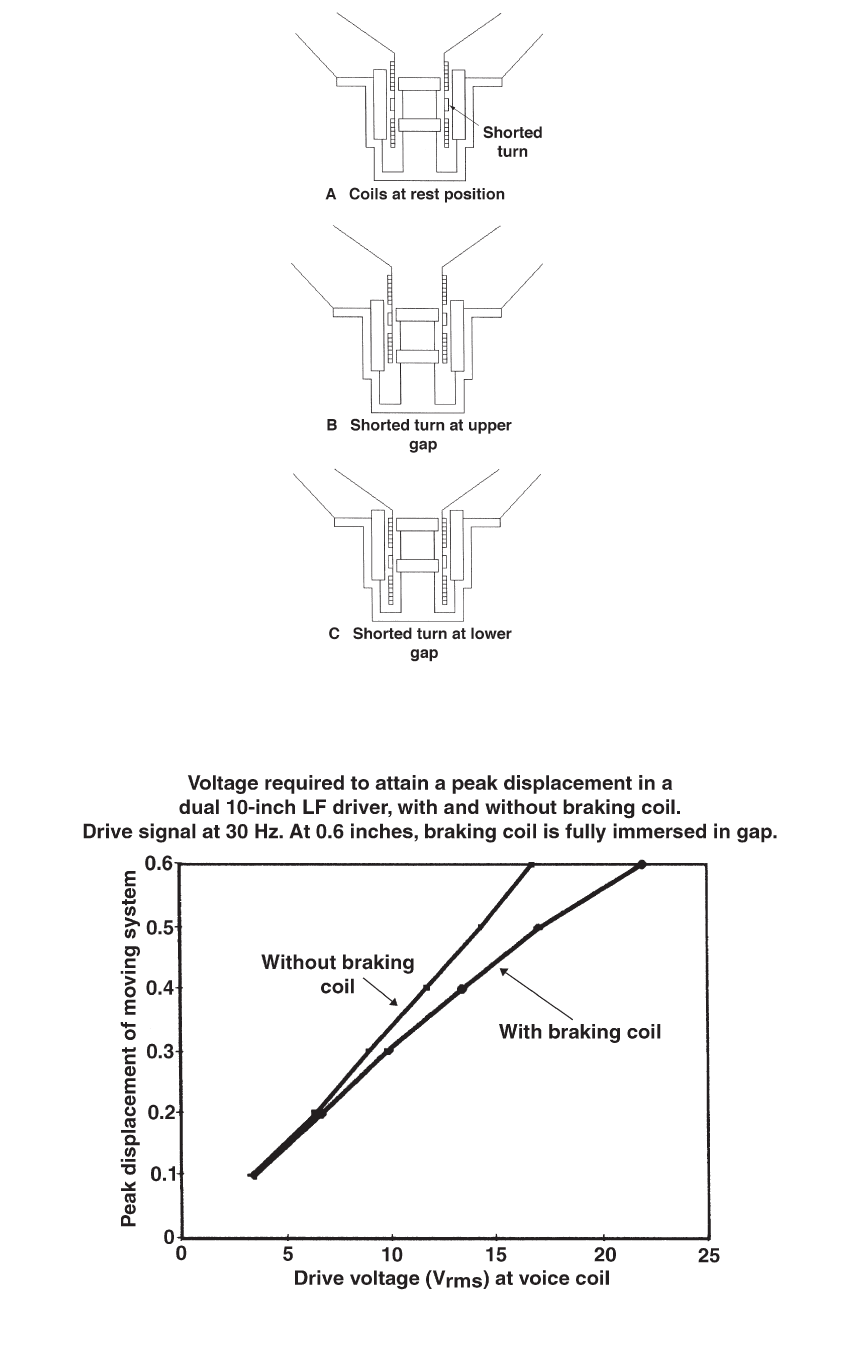
Figure 8 shows three section views of an LF
driver using a braking coil. The moving system
at rest is shown at
A
; the moving system at the
upper extreme of displacement is shown at
B
;
and the moving system at the lower extreme of
displacement is shown at
C
.
At the rest position
A
, the short-circuited brak-
ing coil is well outside the influence of either
the upper or lower magnetic gap and as a
result does nothing.
At
B
, the cone has moved to its maximum for-
ward position, and the braking coil is fully
immersed in the upper magnetic gap. As this
takes place a counter-current is developed in
the braking coil that causes a reverse force in
opposition to the cone’s movement. At
C
, we
see the opposite reaction as the cone’s move-
ment reaches its maximum inward position.
Figure 9 shows the effect of the dynamic brak-
ing coil in terms of displacement versus loud-
speaker drive voltage. The data shows the
beneficial restraint of excessive cone motion
under high drive conditions, which translates
into reduced distortion.
Figure 7. Second and third harmonic distortion components raised 20 dB
relative to the fundamental, in the 2268H driver.
The model 2268H 460 mm (18-inch) Driver:
Figure 7 shows a set of data for the model
2268H driver, which is intended for subwoofer
use in the same general performance category
as the traditional ferrite VGC™ Vented Gap
Cooled 2242H driver. Second harmonic distor-
tion is 10% at a frequency of about 33 Hz, and
overall distortion from about 50 Hz upward is
well below 3% at 115 dB SPL output at 1m.
7
Figure 8. The shorted-turn dynamic braking coil. Cone at rest position (A); cone
at maximum outward position (B); cone at maximum inward position (C).
Figure 9. Cone excursion versus signal voltage with and without
braking coil in model 252 driver.

A Harman International Company
JBL Professional
8500 Balboa Boulevard
Northridge, California 91329 U.S.A. TN VOL 1 NO 33
CRP 2M
6/05
© Copyright 2004 JBL Professional
References:
1. JBL Technical Note Volume 3, Number 2A, JBL’s New LSR6300 Series Studio Monitors, JBL
Professional (Northridge, CA, 2004)
2. Button, D.,”Magnetic Circuit Design Methodology for Dual-Coil Transducers,”
J. Audio Engineering
Society
, Volume 50, Number 6 (June 2002)
3. Eargle, J.,
The Loudspeaker Handbook
, 2nd edition, Kluwer Academic Press (Boston 2003)
4. Borwick, J., editor,
Loudspeaker and Headphone Handbook
, 3rd ed., Focal Press (Boston 2001)
5. U.S. Patent Number 5,748,760, “Dual Coil Drive with Multipurpose Housing”
6. U.S. Patent Number 5,828,767, “Inductive Braking in a Dual Coil Speaker Driver Unit”
7. U.S. Patent Number 6,768,806, “Shorting-Rings in Dual-Coil Dual Gap Loudspeaker Drivers”
8. U.S. Patent Number 6,774,510, “Electromagnetic Motor with Flux Stabilization Ring, Saturation
Tips, and Radiator”
