JBL Technical Note Volume 1 Number 21 Tn V1n21
User Manual: JBL JBL - Manuals+
Open the PDF directly: View PDF ![]() .
.
Page Count: 4
Technical Note, Volume 1, Number 21
JBL’s New Optimized Aperture™
Horns and Low Distortion Drivers
Introduction:
Except in their initial historical development, high
frequency horns and their associated compression
drivers have normally been designed independently of
each other. The reason is of course that drivers of a
given exit diameter are normally expected to work with
the appropriate family of horns, old and new. JBL's
large format family of 100 mm (4 in) diaphragm drivers
is a clear example of this. When the JBL 375
compression driver was designed during the fifties, it
was based on the exit geometry of the original Western
Electric 594 driver. Subsequent variations, such as the
JBL 2441, 2445, and 2450 family all maintained the
original exit geometry and were designed to work with
four decades of horn hardware with 50 mm (2 in) throat
diameter.
As part of JBL's ongoing research in horn/driver
acoustic relationships, it became apparent that
significant improvements could be made in non-linear
performance at high output levels in horn systems if
the exit geometry could be changed. Specifically, the
generation of second and third harmonic distortion at
high levels could be greatly reduced through a more
rapid flare rate from the driver into the horn, and in
order to do this both new drivers and new horns would
have to be developed simultaneously.
JBL has embarked on such a program, and the
driver models 2447 and 2451 have been developed.
These are both 100 mm (4 in) diaphragm drivers with
38 mm (1.5 in) exit diameter. Three medium size
format horn models 2352, 2353, and 2354, offering 90
by 40, 60 by 40, and 40 by 20 degree coverage, have
been designed to work with these drivers. We have
addressed the following points in the new coordinated
designs:
1. Phasing plug coupled directly to the horn throat.
2. Lower distortion than earlier JBL and
competitive combinations.
3. JBL's traditional 100 mm (4 in) titanium
diaphragm integral to the design.
4. Excellent pattern control, extending down to the
crossover range.
5. Consistent on-axis frequency response, model
to model.
While much of this information is apparent from
studying the product specification sheets, we have
developed this Technical Note for the purpose of
showing relevant competitive information on distortion
and pattern control. We will present distortion
measurements on three 90 by 40 degree horn/driver
combinations and show beamwidth data on three
combinations of 90 by 40 and 60 by 40 degree horns.
Background:
As discussed in JBL Technical Note Volume One,
Number Eight, second harmonic distortion in
horn/driver combinations is due to thermodynamic air
overload and, for a given level and driving frequency,
the distortion is inversely proportional to the design
cutoff frequency of the horn. Actually, the exponential
horn flare begins at the diaphragm and is initially
established through the relatively short openings of the
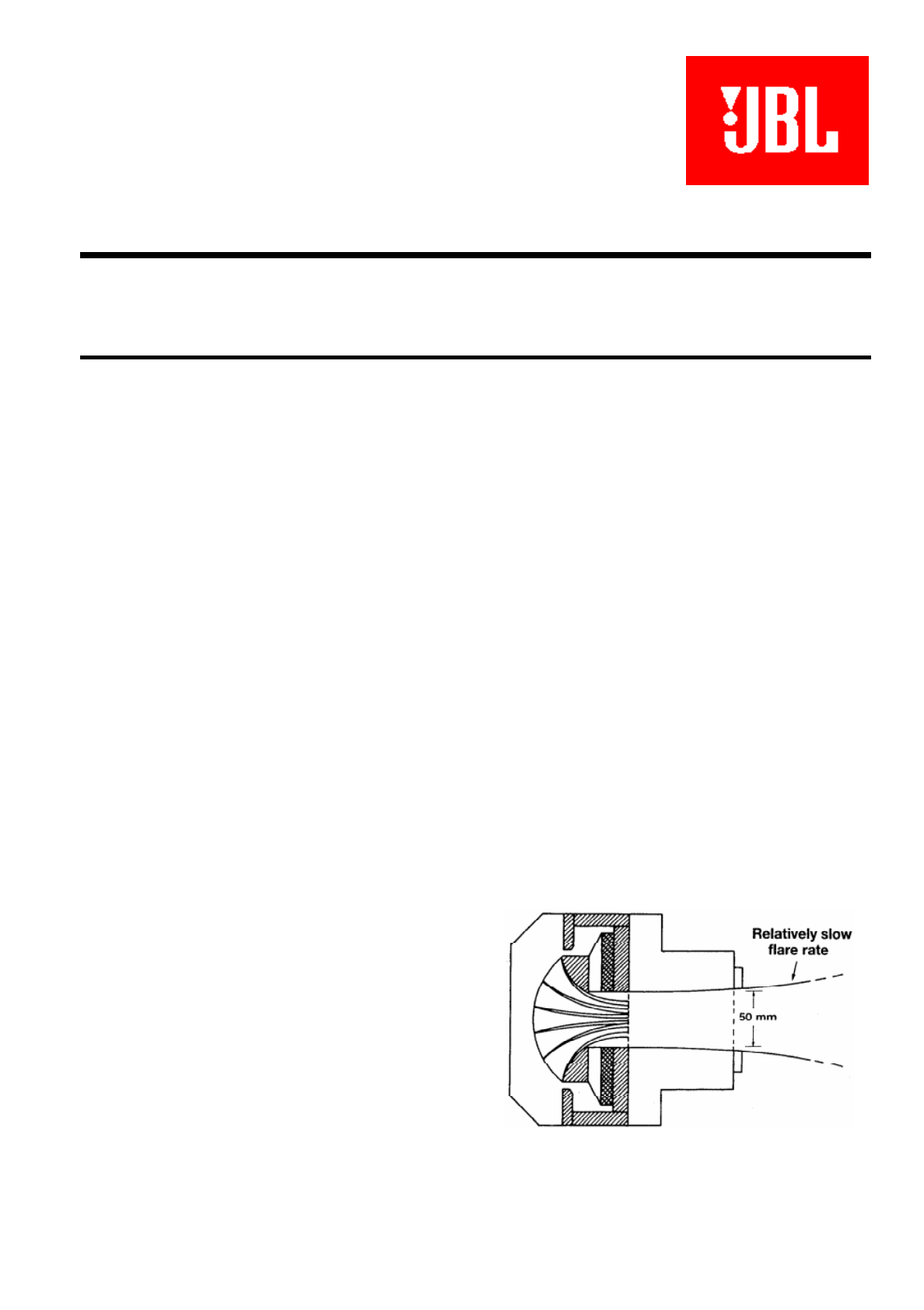
phasing plug. As shown in Figure 1 A, the older driver
technology had a built-in coupler that provided a slow
flare from the 38 mm (1.5 in) diameter of the phasing
plug to the 50 mm (2 in) diameter at the driver's exit.
The original reason for this was to allow internal space
in the driver for relatively deep magnet structures or
field coils.
Figure 1A. Old driver configuration.
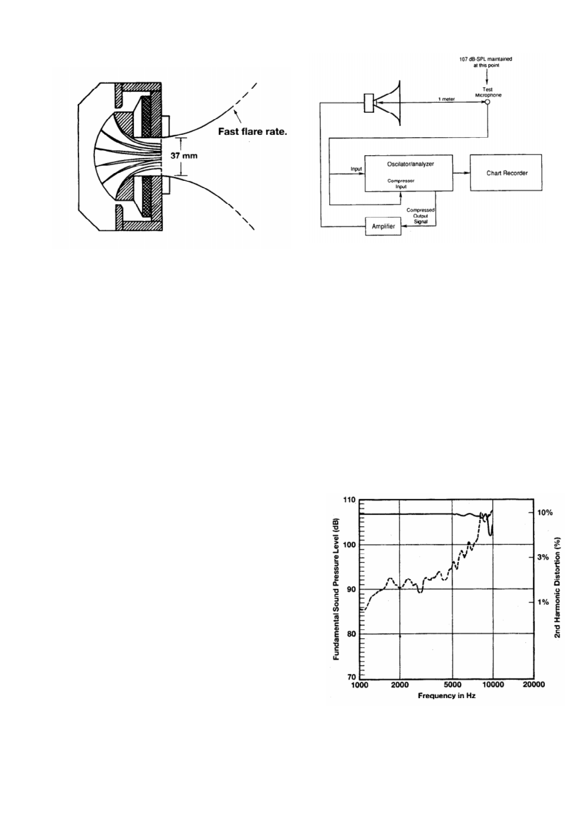
Figure 1B. New driver configuration.
Today, with very small, high energy neodymium
magnets and thin profile ferrite magnets, we do not
need that space. The overall depth of the driver can be
significantly reduced, as shown in Figure 1 B, providing
a relatively rapid flare into the throat of the horn.
By our calculations, the initial flare rate in the older
driver design was approximately 160 Hz, reflecting the
need to drive the very large horns that were used in
early motion picture systems. Today, we can double or
quadruple that flare rate, inasmuch as many horns are
now intended for nominal crossover at 800 Hz.
Rapid flare rates offer an opportunity to make
improvements in high frequency pattern control. Since
the exit of the phasing plug is virtually at the apex of
the horn, there is normally an excellent sight line into
the phasing plug, even at the extremes of angular
coverage; this is virtually a guarantee that high
frequency signals will illuminate the entire wave guide
and show little tendency to beam on axis.
Distortion Measurements:
Figure 2 shows the basic setup for measuring
second harmonic distortion. For these measurements,
the output level at one meter from the diffraction slot of
the horn was carefully maintained at 107 dB SPL
through the use of the compressor in the B&K test
gear. This level corresponds to 87 dB SPL at 10
meters (33 ft), and thus represents normal application
of these horns. The action of the compressor
simulates, on swept sine wave input signals, flat
equalization of the system on axis, as would be the
case in real world equalization practice for many
applications. The total range of compression was about
15 dB.
The three horn/driver combinations used in these
measurements were:
1. JBL 2380/2450
2. JBL 2352/2451
3. EV HP940/DH1A.
Figure 2. Block diagram of test setup for
measuring distortion.
These systems are commercially equivalent in
terms of nominal pattern control, and the horns are
medium format in size. The use of the B&K
compression circuitry enables a direct comparison of
distortion, as a function of output level, to be made by
inspection.
The JBL 2380/2450 combination is shown in
Figure 3A. The compressed fundamental is shown as
the solid line. Second harmonic distortion (dashed
curve) has been raised 20 dB, and distortion
percentage is indicated along the right axis of the
graph. For this combination, second harmonic
distortion lies between 1 % and 3% from 1 kHz to
about 5.5 kHz. Between 5 kHz and 10 kHz it rises to a
little over 10%.
Figure 3. Hom/Driver Distortion Measurements.
A. JBL 2380/24SO combination.
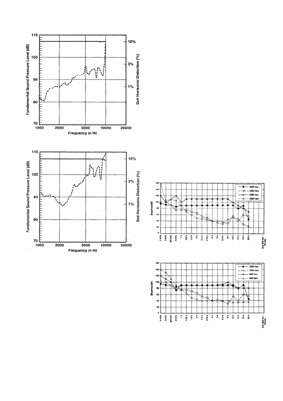
B. JBL 2352/2451 combination.
C. EV HP940/DH1A combination.
The JBL 2352/2451 combination is shown at 3B.
Again, second harmonic distortion has been raised 20
dB. Here, midband distortion lies below 1 % up to
about 2.5 kHz, reaching a value of 3% at about 9 kHz.
The EV HP940/DH1A combination is shown at 3C.
Note the rise in distortion between 1 and 2 kHz; this
appears to be due to mechanical suspension
nonlinearity in the driver rather than to thermodynamic
effects. In general, the distortion is significantly higher
than that of either the JBL 2380/2450 or JBL
2352/2451 combination.
Beamwidth Measurements:
As a rule, JBL publishes beamwidth data plotted
on a logarithmic vertical scale, since that scale relates
inversely to directivity index. However, in Figures 4 and
5, a linear vertical scale is used for beamwidth
measurements since it provides better resolution in the
80 to 120 degree range for ease in making competitive
comparisons.
Figure 4 shows beamwidth performance versus
frequency for the JBL 2352, as compared with the
JBL2380 and the EV HP940. At 4A the new JBL 2352
is compared with the older JBL2380. While both horns
have much in common, note that the horizontal
beamwidth is virtually flat out to 16 kHz. Also, the
pattern control in the 400 Hz to 1 kHz range is much
smoother in the new horn.
Figure 4B compares the JBL2352 with the EV
HP940. The 2352 exhibits better control in the
horizontal plane, while the EV HP940 horn exhibits
smoother control in the vertical plane. Overall, the 2352
exhibits smoother pattern control in the 400 Hz to 1
kHz range.
Figure 4. -6 dB Beamwidth Measurements.
A. JBL 2352 and 2380 comparison.
B. JBL 2352 and EV HP940 comparison.
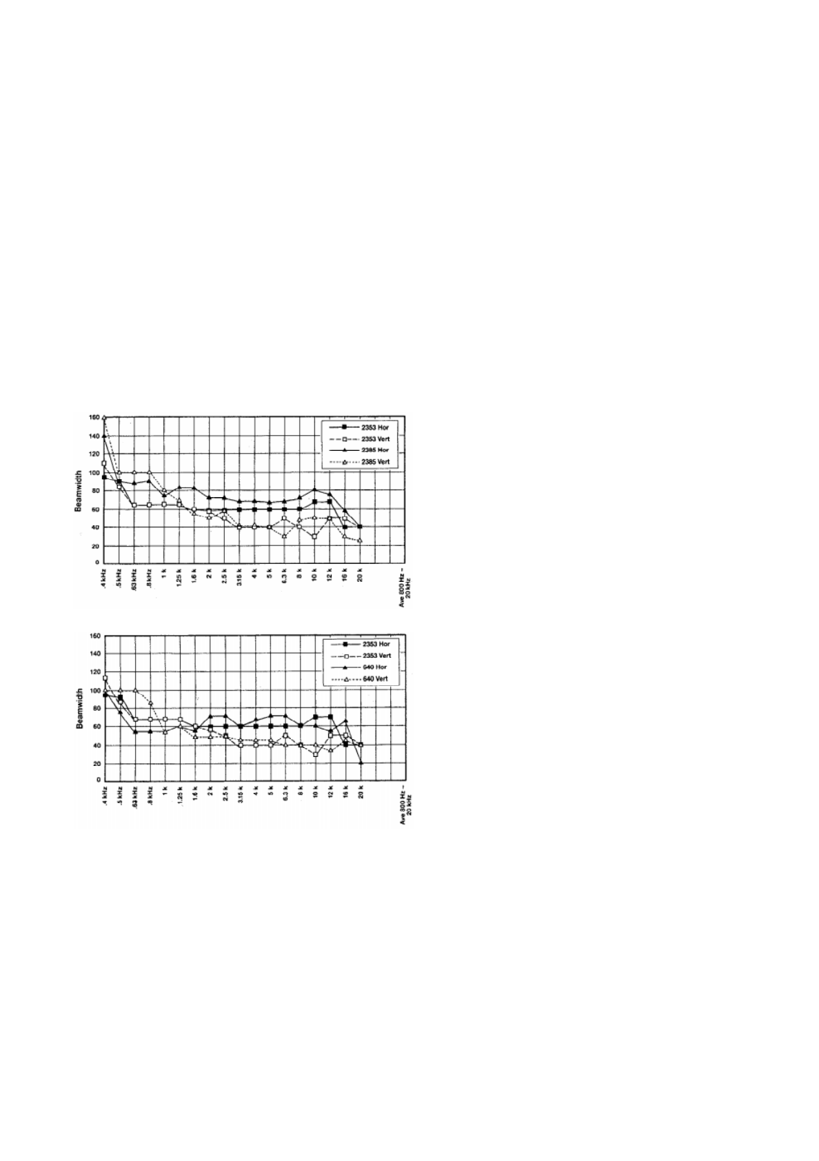
Figure 5 shows beamwidth performance versus
frequency for the JBL 2353, as compared with the JBL
2385 and the EV HP640. At 5A the new JBL 2353 is
compared with the older JBL2385. Note that the 2353's
horizontal beamwidth follows its target 60degree
response from 630 Hz to 12 kHz. Vertical pattern
control is maintained from 2.5 kHz to 16 kHz within +10
degrees.
The JBL2353 and EV HP640 are compared in
Figure 5B. Note that the 2353 exhibits horizontal
pattern control that is within 10 degrees of the target 60
degrees from 630 Hz to 12 kHz. Both horns have
roughly equivalent vertical pattern control. As with the
90 by 40 degree horn, note that the 2353 maintains
better pattern control in the 500 Hz to 1 kHz range than
either the older JBL2385 or the EV HP640.
Figure 5. -6 dB Beamwidth Measurements.
A. JBL 2353 and 2385 comparison.
B. JBL 2353 and EV HP640 comparison.
Conclusions:
JBL's new Optimized Aperture horns and their
associated drivers offer a significant reduction in
distortion when compared to all earlier JBL horns and
all competitive models. These improvements in
distortion have been attained with no loss of pattern
control, as we can see when they are directly
compared with the earlier JBL 2380 series Flat-Front
Bi-Radial designs. In some cases the new horns offer
better pattern control than the older Flat-Fronts. The
combination of large diaphragm diameter and rapid
flare exit geometry points the way for future
development for all classes of horns.
JBL Professional
8500 Balboa Boulevard, PO. Box 2200
Northridge, California 91329 U.S A.
A Harman International Company
3/94 P1221
