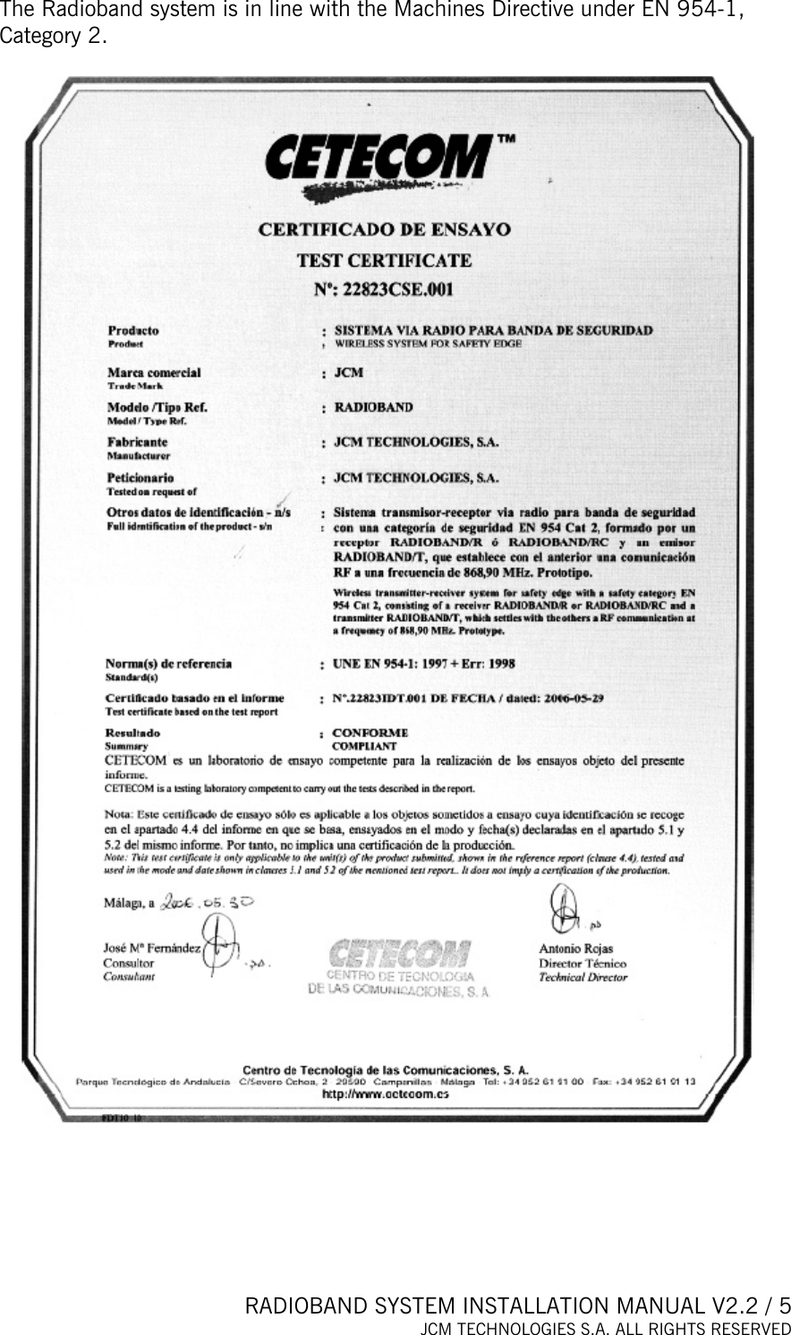
JCM Technologies RADIOBAND-T Remote Control Transceiver User Manual

JCM Technologies, S.A. Remote Control Transceiver

User Manual

 RADIOBAND SYSTEM INSTALLATION MANUAL V2.2 / 1 JCM TECHNOLOGIES S.A. ALL RIGHTS RESERVED                 RADIOBAND SYSTEM INSTALLATION MANUAL
 RADIOBAND SYSTEM INSTALLATION MANUAL V2.2 / 2 JCM TECHNOLOGIES S.A. ALL RIGHTS RESERVED  CONTENTS  CONTENTS ...................................................................................................................... 2 1. INTRODUCTION ......................................................................................................... 3 1.1 System description............................................................................................... 3 1.2 Normative requirements ...................................................................................... 3 2. THE SYSTEM .............................................................................................................. 6 2.1 RADIOBAND/T...................................................................................................... 6 2.2 RADIOBAND/R ..................................................................................................... 9 2.3 RADIOBAND/RC-RCS ........................................................................................ 16 2.4 COMPATIBILITY TABLE .................................................................................... 20 3. AUTO-TEST FUNCTION........................................................................................... 21 3.1 AUTO-TEST DESCRIPTION............................................................................... 21 3.2 RADIOBAND/RCS CONNECTIONS................................................................... 22 4. RADIOBAND SYSTEM INSTALLATION RECOMMENDATIONS........................... 23 4.1 Installation on roller door with control panel and RADIOBAND/R. ............... 23 4.2 Installation on two-leafed swing door with control panel and RADIOBAND/RC-RCS. .............................................................................................. 23 4.3 Installation on horizontal sectional door with control panel and RADIOBAND/R. ......................................................................................................... 24 4.4. Installation on angled sectional door with control panel and RADIOBAND/R..................................................................................................................................... 24 4.5 Installation on stackable sectional door with control panel and RADIOBAND/R. ......................................................................................................... 25 4.6 Installation on one-leafed residential folding door with control panel with RADIOBAND/RC-RCS card connector..................................................................... 25 4.7 Installation on one-leafed folding door for communities with control panel and RADIOBAND/R................................................................................................... 26 4.8 Installation on one-leafed sliding door with control panel and RADIOBAND/R..................................................................................................................................... 26 4.9 Installation on sliding door with control panel and RADIOBAND/RC-RCS card connector........................................................................................................... 27 4.10 Installation on guillotine door with control panel and RADIOBAND/R....... 27 5. JCM CONTROL PANEL DIAGRAM FOR CONNECTION TO THE RADIOBAND SYSTEM.......................................................................................................................... 28
 RADIOBAND SYSTEM INSTALLATION MANUAL V2.2 / 3 JCM TECHNOLOGIES S.A. ALL RIGHTS RESERVED  1. INTRODUCTION  1.1 System description  The Radioband system is designed for installation with a safety edge in garage door installations.  This system allows for wireless safety edge – control panel connection.   To install this system, you must follow the advice included in this manual and take the requirements of the applicable normative into account.   1.2 Normative requirements  The directives applicable to this system are:  -  98/37/EC Machines Directive -  73/23/EEC Low Voltage Directive -  2004/108/EC Electromagnetic Compatibility Directive -  R&TTE 1999/5/EC Radio and telecommunication terminal equipment Directive  Below are some of the requirements of the applicable harmonised standards:    In accordance with the European low voltage directive, you are informed of the following requirements: · For permanently connected equipment, an easily accessible connection device must be incorporated into the cabling. · This equipment must be installed in a vertical position and firmly fixed to the structure of the building. · This equipment may only be handled by a specialized installer, by maintenance staff or by a properly instructed operator.  · The instructions for use of this equipment must always remain in the possession of the user.  · Terminals with a maximum section of 3.8mm2 must be used to connect the cables.  - The frequency of the Radioband system does not interfere in any way with the 868 MHz remote control systems. However a  signal centred at 868,9MHz may cause a delay on the reaction of the system. - Always connect the door structure and metal parts to an earthing connection.  - Do not share the power and signal supply.
 RADIOBAND SYSTEM INSTALLATION MANUAL V2.2 / 4 JCM TECHNOLOGIES S.A. ALL RIGHTS RESERVED  JCM TECHNOLOGIES, S.A. declares herewith that the product RADIOBAND/T, RADIOBAND/R, RADIOBAND/RC-RCS complies with the relevant fundamental requirements as per Article 3 of the R&TTE Directive 1999/5/EG, insofar as the product is used correctly.  This device complies with Part 15 of the FCC Rules. Operation is subject to the following two conditions: (1) this device may not cause harmful interference, and (2) this device must accept any interference received, including interference that may cause undesired operation.  To comply with FCC rules, adjustment or modifications of this receiver and/or transmitter are prohibited, except for changing the code setting or replacing the battery. THERE ARE NO OTHER USER SERVICEABLE PARTS. Any other changes made, not expressly approved by JCM Technologies, S A could void the user's authority to operate the equipment.
 RADIOBAND SYSTEM INSTALLATION MANUAL V2.2 / 5 JCM TECHNOLOGIES S.A. ALL RIGHTS RESERVED   The Radioband system is in line with the Machines Directive under EN 954-1, Category 2.
 RADIOBAND SYSTEM INSTALLATION MANUAL V2.2 / 6 JCM TECHNOLOGIES S.A. ALL RIGHTS RESERVED  2. THE SYSTEM  2.1 RADIOBAND/T        Operating frequency  868.90MHz Power supply  3V DC  (2 x 1.5V LR03 AAA) Op. consumption  12mA Radiated power  < 25mW Op. temperature  -20ºC - +55ºC Seal IP67 Dimensions  85 x 53 x 36mm Range (guaranteed)  10m Battery life   2 years Minimum time between two RADIOBAND/T activations (for complying with the R&TTE Directive) 7 min
 RADIOBAND SYSTEM INSTALLATION MANUAL V2.2 / 7 JCM TECHNOLOGIES S.A. ALL RIGHTS RESERVED     INSTALLATION AND CONNECTIONS Fix the back of the box to the door. Install the transmitter following the technical manual and avoid placing metallic surfaces between the receiver and the transmitter. Pass the cables through the bottom of the transmitter. Connect a resistive 8K2 safety band directly to terminal B1 and ensure that the safety edge keeps totally waterproof. Fix the front of the transmitter to the back with the screws supplied for the purpose. N.B.: If a non-resistive element (with a contact normally closed) needs to be connected, the jumper JP4 must be bridged. This application does not comply with safety standard EN 12453 for the use of motorised garage doors, since the connection of the resistive element to the RADIOBAND/T is not checked.  OPERATION The receiver checks that all the programmed bands are working properly. If a band is activated or if there is an error in its operation, the receiver activates the output relay.   PROGRAMMING RADIOBAND/T If the receiver is in programming, press the transmitter button to programme it into the receiver.  TRANSMITTER BATTERY LOW INDICATOR (RADIOBAND/T) If the battery of a transmitter programmed into the receiver becomes low, it will give out 4 short signals every 20 seconds. If there is more than one transmitter programmed, the safety band must be activated to check whether the receiver then makes these 4 short signals. If this is the case, the transmitter connected to the activated safety band will be the one with the low battery. Change it.   CHANGING THE BATTERY Remove the box cover. The batteries are positioned on the back of the cover. Replace the two used batteries with new ones, taking into account the polarity indicated by the connector. Check that the new batteries support the same temperature range as those they are replacing.
 RADIOBAND SYSTEM INSTALLATION MANUAL V2.2 / 8 JCM TECHNOLOGIES S.A. ALL RIGHTS RESERVED  INSTALLATION ADVICE  Install the equipment so that the cable outlet is at the bottomDo not fit the equipment at ground levelIn installations likely to have range problems between the transmitter and the receiver, the antenna must stand vertically from the hole in the gland  Do not place metal surfaces between the transmitter and the receiverThe transmitter and receiver anten amust be parallel to each other for optimum signal receptionn     * Once the system has been installed, check it works correctly by enabling the safety edge on the ends of the door.
 RADIOBAND SYSTEM INSTALLATION MANUAL V2.2 / 9 JCM TECHNOLOGIES S.A. ALL RIGHTS RESERVED  2.2 RADIOBAND/R    Frequency 868.90MHz Memory  6 Radioband-T (3 on relay 1, 3 on relay 2) Number of relays  2 relays Power supply  12/24V AC/DC Power supply range  9-35V DC 8-28V AC Relay contacts  1A Consumption: idle/op.  18mA/80mA Self-test input  2 0/12/24V AC/DC inputs with selectable polarity  Power   < 25mW Op. temperature  -20ºC to +85ºC Seal  IP54 (with IP65 cable seals) Box size  82 x 190 x 40mm Range (guaranteed)  10 metres
 RADIOBAND SYSTEM INSTALLATION MANUAL V2.2 / 10 JCM TECHNOLOGIES S.A. ALL RIGHTS RESERVED  INSTALLATION AND CONNECTIONS Fix the back of the box to the wall, using the wall plugs and screws supplied. Install the receiver, close to the door and avoid metal surfaces between the receiver and the transmitter. Pass the cables through the bottom of the receiver. Connect the power cables to the terminals of the printed circuit, following the indications of the connections diagram. Store RADIOBAND-T. Fix the front of the receiver to the back with the screws supplied for the purpose.  1-  Power supply 12/24V AC/DC: (+) 2-  Power supply 12/24V AC/DC (-) 3,4- R1: Connection to the safety band input of the control panel (resistive contact 8.2kΩ)  with jumper in position BS1 (see CONNECTIONS Figure 1). Or to the control panel safety contact input (NC) with jumper in position CS1 (see CONNECTION Figure 2). 5,6- R2: Connection to a second safety band input of the control panel (resistive contact 8.2kΩ) with jumper in position BS2. Or to the control panel safety contact input (NC) with jumper in position CS2. 7-  AUTOTEST: Common connection safety self-test (-). See CONNECTIONS Figure 3 and table POLARIZED SELF-TEST. 8-  AUTOTEST: Self-test connection for R1. See CONNECTIONS Figure 3 and table POLARIZED AUTO-TEST. 9-  AUTOTEST: Self-test connection for R2. See CONNECTIONS Figure 3 and table POLARIZED AUTO-TEST.   POLARIZED AUTO-TEST Check the auto-test output on the control panel, in standby, to see whether the voltage is 0V (inverted test input) or 12/24V AC/DC (positive polarity). The auto-test signal of the panel must remain at its maximum for 2 seconds.   Autotest output in standby Autotest output activated Polarity type Jumper ATEST POL  ATEST1 ATEST2 0V 12/24V Positive OFF  Connected*  Connected* Connection to a equipment with autotest  12/24V 0V  inverted  ON  Connected* Connected* Connection to a equipment without autotest**  --- --- ---  OFF No connected No connected  * N.B.: Only connect the auto-test output to be used.       ** Where the auto-test is not used, the system is not checked at the start of the operation, which means that security normative EN 12453 regarding the use of motorised garage doors is, in some cases, not complied with.
 RADIOBAND SYSTEM INSTALLATION MANUAL V2.2 / 11 JCM TECHNOLOGIES S.A. ALL RIGHTS RESERVED  LIGHT INDICATORS RADIOBAND/R-RC-RCS In operation  In programming Relay 1 LED  Normally off. Indicates the status of the relay output.  If R1 is not connected, on. On. Indicates the channel to be programmed. Relay 2 LED  Normally off. Indicates the status of the relay output.  If R2 is not connected, on. On. Indicates the channel to be programmed.  OPERATION The receiver checks that all the programmed bands are working properly. If a band is activated or if there is an error in its operation, the receiver activates the output relay.   MANUAL PROGRAMMING  RADIOBAND-R makes it possible to store 6 RADIOBAND-Ts (3 on Relay 1 and 3 on Relay 2). Press the receiver programming PROG button for 1s; a sound signal will be heard. The receiver will go into programming the first relay. If the programming button is kept pressed, the receiver will go into programming the second relay, moving cyclically from one really to another. Once the programming relay has been chosen for the transmitter you want to start using, send the programming code by pressing the transmitter. Every time a transmitter is programmed, the receiver will emit a sound signal for 0.5s. If 10 seconds pass without programming, the receiver will go out of programming mode, emitting two 1s sound signals. If, when programming a transmitter, the receiver's memory is full, it will emit 7 sound signals lasting 0.5s and come out of programming. Note: For a right operation of the system, the transmitter has to be programmed in one receiver only.  RADIOBAND/T replacement: In case you need to replace a RADIOBAND/T, it is necessary to reset the system and reprogram all RADIOBAND/T used in the installation.  SYSTEM CHECK This function is used to check the operation and range of all the devices once the installation has been carried out.   Press the receiver’s CHECK button for at least 1 second to enter check mode. The indicator light will come on and four beeps will be heard.  Perform a complete door opening and closing manoeuvre.  During the system check a beep will be heard every 1,5 seconds.  CORRECT OPERATION OF THE SYSTEM If no other acoustic signal is heard on completing the manoeuvre, the system is operating correctly. Either press the CHECK button again or wait 5 minutes and the RADIOBAND/R will exit checking automatically, indicating with two beeps that the check has been correct. The check indicator light will go out.
 RADIOBAND SYSTEM INSTALLATION MANUAL V2.2 / 12 JCM TECHNOLOGIES S.A. ALL RIGHTS RESERVED  DETECTION OF BAND FAILURE If the communication with a RADIOBAND/T fails during checking, or the communication is deficient (for instance, too many communication retries or poor coverage), the RADIOBAND/R emits three consecutive beeps, indicating that an error has occurred. Halt the door manoeuvre and press the safety bands installed to detect what has failed.  -  If a single beep is heard on pressing a band, this means that the band is correct.  -  If three consecutive beeps are heard on pressing the band, this means that the band has failed.  In this event, it is recommended changing the orientation of the transmitting-receiving aerials or installing an AED-868 or FLAT-868 outdoor aerial to ensure the desired range. On exiting check mode, seven consecutive beeps will be heard and the indicator light will flash continuously. Perform another system check until the result is correct.  Signal coverage On pressing each of the installed bands, continuous flashes, ranging from 1 to 5, indicate the signal coverage for each of these. Number of check LED flashes Coverage  Result of check 1  Very weak  Band failure 2 Weak OK 3 Normal OK 4 Good OK 5 Very good OK  TOTAL RESET In programming mode, keep the programming PROG button pressed down and make a bridge with the "MR" reset jumper for 3s. The receiver will emit 10 warning sound signals and then more at a faster frequency, indicating that the operation has been carried out. The receiver will stay in programming mode. If 10 seconds elapse without programming, or if you press the programming button quickly, the receiver will go out of programming mode, emitting two 1s sound signals.  TRANSMITTER BATTERY LOW INDICATOR (RADIOBAND/T) If the battery of a transmitter programmed into the receiver becomes low, it will give out 4 short signals every 20 seconds. If there is more than one transmitter programmed, the safety band must be activated to check whether the receiver then makes these 4 short signals. If this is the case, the transmitter connected to the activated safety band will be the one with the low battery. Change it.
 RADIOBAND SYSTEM INSTALLATION MANUAL V2.2 / 13 JCM TECHNOLOGIES S.A. ALL RIGHTS RESERVED  INSTALLATION ADVICE  Do not fit the equipment at ground levelThe transmitter and receiver antenna must be parallel to each other for optimum signal reception    Do not place metal surfaces between the transmitter and the receiverThe transmitter and receiver anten amust be parallel to each other for optimum signal receptionn
 RADIOBAND SYSTEM INSTALLATION MANUAL V2.2 / 14 JCM TECHNOLOGIES S.A. ALL RIGHTS RESERVED  a) Connection to safety edge inlet   b) Connection to security contact inlet
 RADIOBAND SYSTEM INSTALLATION MANUAL V2.2 / 15 JCM TECHNOLOGIES S.A. ALL RIGHTS RESERVED  c) Auto-test connection with negative polarisation      d) Auto-test connection with positive polarisation     * Once the system has been installed, check it works correctly by enabling the safety edge on the ends of the door.
 RADIOBAND SYSTEM INSTALLATION MANUAL V2.2 / 16 JCM TECHNOLOGIES S.A. ALL RIGHTS RESERVED  2.3 RADIOBAND/RC-RCS        Frequency 868.90MHz Memory  6 Radioband-T  Power supply  pluggable Power supply range  --- Consumption: idle/op.  18mA Self-test input  incorporated Power   < 25mW Op. temperature  -20ºC to +85ºC Seal IP20 Box size  50x20x17mm Range (guaranteed)  10 metres
 RADIOBAND SYSTEM INSTALLATION MANUAL V2.2 / 17 JCM TECHNOLOGIES S.A. ALL RIGHTS RESERVED  INSTALLATION AND CONNECTIONS Connection to a control panel using a connector for safety devices.  LIGHT INDICATORS RADIOBAND/R-RC-RCS In operation  In programming Relay 1 LED  Normally off. Indicates the status of the relay output.  If R1 is not connected, on. On. Indicates the channel to be programmed. Relay 2 LED  Normally off. Indicates the status of the relay output.  If R2 is not connected, on. On. Indicates the channel to be programmed.  OPERATION The receiver checks that all the programmed bands are working properly. If a band is activated or if there is an error in its operation, the receiver activates the output relay.   MANUAL PROGRAMMING  RADIOBAND/RC-RCS makes it possible to store 6 RADIOBAND-Ts (3 on Relay 1 and 3 on Relay 2). Press the receiver programming PROG button for 1s; a sound signal will be heard. The receiver will enter safety band closing programming mode (BSC). If the programming button is kept pressed, the receiver will enter  safety band opening programming mode (BSO), moving cyclically from one really to another. Once the programming relay has been chosen for the transmitter you want to start using, send the programming code by pressing the transmitter. Every time a transmitter is programmed, the receiver will emit a sound signal for 0.5s. If 10 seconds pass without programming, the receiver will go out of programming mode, emitting two 1s sound signals. If, when programming a transmitter, the receiver's memory is full, it will emit 7 sound signals lasting 0.5s and come out of programming. Note: For a right operation of the system, the transmitter has to be programmed in one receiver only.  RADIOBAND/T replacement: In case you need to replace a RADIOBAND/T, it is necessary to reset the system and reprogram all RADIOBAND/T used in the installation.  SYSTEM CHECK This function is used to check the operation and range of all the devices once the installation has been carried out.   Press the receiver’s CHECK button for at least one second to enter check mode. The indicator light will come on and four beeps will be heard.  Perform a complete door opening and closing manoeuvre.  During the system check a beep will be heard every 1,5 seconds.  CORRECT OPERATION OF THE SYSTEM If no other acoustic signal is heard on completing the manoeuvre, the system is operating correctly. Either press the CHECK button again or wait 5 minutes and the
 RADIOBAND SYSTEM INSTALLATION MANUAL V2.2 / 18 JCM TECHNOLOGIES S.A. ALL RIGHTS RESERVED  RADIOBAND/RC-RCS will exit checking automatically, indicating with two beeps that the check has been correct. The check indicator light will go out.   DETECTION OF BAND FAILURE If the communication with a RADIOBAND/T fails during checking, or the communication is deficient (for instance, too many communication retries or poor coverage), the RADIOBAND/RC-RCS emits three consecutive beeps, indicating that an error has occurred. Halt the door manoeuvre and press the safety bands installed to detect what has failed.  -  If a single beep is heard on pressing a band, this means that the band is correct.  -  If three consecutive beeps are heard on pressing the band, this means that the band has failed.  In this event, it is recommended changing the orientation of the transmitting-receiving aerials or installing an AED-868 or FLAT-868 outdoor aerial to ensure the desired range. On exiting check mode, seven consecutive beeps will be heard and the indicator light will flash continuously. Perform another system check until the result is correct.  Signal coverage On pressing each of the installed bands, continuous flashes, ranging from 1 to 5, indicate the signal coverage for each of these. Number of check LED flashes Coverage  Result of check 1  Very weak  Band failure 2 Weak OK 3 Normal OK 4 Good OK 5 Very good OK  TOTAL RESET In programming mode, keep the programming PROG button pressed down and make a bridge with the "MR" reset jumper for 3s. The receiver will emit 10 warning sound signals and then more at a faster frequency, indicating that the operation has been carried out. The receiver will stay in programming mode. If 10 seconds elapse without programming, or if you press the programming button quickly, the receiver will go out of programming mode, emitting two 1s sound signals.
 RADIOBAND SYSTEM INSTALLATION MANUAL V2.2 / 19 JCM TECHNOLOGIES S.A. ALL RIGHTS RESERVED  INSTALLATION ADVICE Where an antenna extensionis not installed, place the receivercard antenna in vertical position An AED-868 or FLAT 868 antenna extensionto 868 MHz should be installed for greater range 868MHz AED-868 or FLAT 868antenna extension with RG 58 coaxial cable      * Once the system has been installed, check it works correctly by enabling the safety edge on the ends of the door.
 RADIOBAND SYSTEM INSTALLATION MANUAL V2.2 / 20 JCM TECHNOLOGIES S.A. ALL RIGHTS RESERVED  2.4 COMPATIBILITY TABLE    RADIOBAND/R-RC-RCS (C)  RADIOBAND/R-RC-RCS (D) RADIOBAND/T (A)   No check function  No check function RADIOBAND/T (B)    No check function  With check function A: model without outdoor antenna (WBAND-Ba board) B: model with outdoor antenna (WBAND-Bb board and later)  C: model without CHECK button (/R WBAND-Ia to WBAND-Id board; /RC-RCS WBAND-Qa and WBAND-Qb board) D: model with CHECK button (/R WBAND-Ie board and later; /RC-RCS WBAND-Qc board and later)   N.B.: It is possible to combine RADIOBAND/T units A and B in the same installation, providing the first units programmed are A. This option does not permit the system check function.
 RADIOBAND SYSTEM INSTALLATION MANUAL V2.2 / 21 JCM TECHNOLOGIES S.A. ALL RIGHTS RESERVED  3. AUTO-TEST FUNCTION 3.1 AUTO-TEST DESCRIPTION   Before starting operations, the control panel must check that the entire security system is working correctly.  To make this check, the panel must act on the auto-test signal.  •  AUTO-TEST timing correct                 •  AUTO-TEST timing error                While the auto-test is being run to learn of the status of the RADIOBAND/T, the RADIOBAND/R questions the status of the different Safety edges.  This process ensures the correct working order of the following parts:  •  Safety edge •  RADIOBAND/T (1 or several). •  RF Channel (if there is any interference) •  RADIOBAND/R (control and RF) Autotest CS RADIOBAND/T status Auto-test carried out Autotest OK Tautotest TendThe operation can now be carried out Autotest CS RADIOBAND/T status Auto-test carried out Autotest Error  TMAXautotest TendTHE OPERATION CANNOT BE STARED AS THE AUTO-TEST HAS NOT BEEN SUCCESSFULLY COMPLETED
 RADIOBAND SYSTEM INSTALLATION MANUAL V2.2 / 22 JCM TECHNOLOGIES S.A. ALL RIGHTS RESERVED  Switching the status of the output relay outlet means that the control status and the correct working order of the RADIOBAND/R output relays can be checked.   Description Tmin Ttype Tmax Tauto-test 10ms 375ms 750ms TMAXauto-test   1500ms Tend  50 ms    3.2 RADIOBAND/RCS CONNECTIONS      1- Not connected 2-  RB_S1: Outlet 1 Radioband activation 3- Mass 4-  RB_S2 Outlet 2 Radioband activation 5-  5Vdc power supply 6-  RB_AT-1: Inlet 1 Radioband auto-test  7- Not connected 8-  RB_AT-2: Inlet 2 Radioband auto-test
 RADIOBAND SYSTEM INSTALLATION MANUAL V2.2 / 23 JCM TECHNOLOGIES S.A. ALL RIGHTS RESERVED  4. RADIOBAND SYSTEM INSTALLATION RECOMMENDATIONS  4.1 Installation on roller door with control panel and RADIOBAND/R.       4.2 Installation on two-leafed swing door with control panel and RADIOBAND/RC-RCS.
 RADIOBAND SYSTEM INSTALLATION MANUAL V2.2 / 24 JCM TECHNOLOGIES S.A. ALL RIGHTS RESERVED  4.3 Installation on horizontal sectional door with control panel and RADIOBAND/R.      4.4. Installation on angled sectional door with control panel and RADIOBAND/R.
 RADIOBAND SYSTEM INSTALLATION MANUAL V2.2 / 25 JCM TECHNOLOGIES S.A. ALL RIGHTS RESERVED  4.5 Installation on stackable sectional door with control panel and RADIOBAND/R.    4.6 Installation on one-leafed residential folding door with control panel with RADIOBAND/RC-RCS card connector.  M
 RADIOBAND SYSTEM INSTALLATION MANUAL V2.2 / 26 JCM TECHNOLOGIES S.A. ALL RIGHTS RESERVED  4.7 Installation on one-leafed folding door for communities with control panel and RADIOBAND/R.  4.8 Installation on one-leafed sliding door with control panel and RADIOBAND/R. M
 RADIOBAND SYSTEM INSTALLATION MANUAL V2.2 / 27 JCM TECHNOLOGIES S.A. ALL RIGHTS RESERVED  4.9 Installation on sliding door with control panel and RADIOBAND/RC-RCS card connector.  M  4.10 Installation on guillotine door with control panel and RADIOBAND/R.
 RADIOBAND SYSTEM INSTALLATION MANUAL V2.2 / 28 JCM TECHNOLOGIES S.A. ALL RIGHTS RESERVED  5. JCM CONTROL PANEL DIAGRAM FOR CONNECTION TO THE RADIOBAND SYSTEM  SINGLE-PHASE PANELS  JCM Control panels Applications Description Compatibility with Radioband system START-EU  Roller for  residential and commercial use  Semi-automatic operations. 433 or 868 MHz radio card connection. Start button and safety edge connection. RADIOBAND/R with external power supply   RESIDENT+DCS  Roller for  residential use  Semi-automatic and automatic operations. Built-in 433 MHz receiver. Start/stop button connection, limit switches and security contact on close.  Possible to connect the TBAND card. 24Vac outlet Garage light contact RADIOBAND/R  ROLLER-MOTION  Roller for  residential and commercial use  “Dead-man” operations (using GO-BUTTON or GO- SWITCH), semi-automatic. Built-in 868 MHz receiver. Start button  and safety edge connection. RADIOBAND/R with external power supply  BASIC-EU  Sliding for residential and  community use  Semi-automatic and automatic operations. 433 or 868 MHz radio card connector. Start, pedestrian and stop button connection. Limit switch, safety edge and security contact connection.  Garage light contact 12Vdc outlet RADIOBAND/R MAIN-1T-EU  Swing, folding and sliding for residential and community use   Semi-automatic and automatic operations. 433 or 868 MHz radio card connector. Start and stop button connection. Limit switch,  safety edge and security contact connection.  Traffic light or signal card connector. Garage light contact 24Vac outlet Electro-lock connection. RADIOBAND/R    MAIN-2T-EU Same as MAIN-1T-EU Same as MAIN-1T-EU for 2 motors RADIOBAND/R
 RADIOBAND SYSTEM INSTALLATION MANUAL V2.2 / 29 JCM TECHNOLOGIES S.A. ALL RIGHTS RESERVED  ADVANCE  Swing, folding and sliding for residential and intensive use.  Semi-automatic and automatic operations. Digital programming. Gentle stop.  RADIOBAND and other force limiting device (FORCELIMIT and T-HALL) connector. 433 or 868 MHz card connector. Start and stop button connection. Limit switch, Limit switch, safety edge and security contact connection.  Electro-lock connection. Traffic light card or signal card connector. Garage light contact 24Vac outlet Auto-test outlet. RADIOBAND/RC or RADIOBAND/R with negative polarisation auto-test function  STANDARD-1T-EU  Swing, folding and sliding for residential and community use  Semi-automatic and automatic operations. Gentle stop.  433 or 868 MHz radio card connector. Start, pedestrian, stop, open and close button connection. Limit switch, safety edge and security contact connection.  Traffic light connector. Garage light and signal contact 24Vac outlet Electro-lock connection. RADIOBAND/R     STANDARD-2T-EU Same as STANDARD-1T-EU Same as STANDARD-1T-EU for 2 motors  RADIOBAND/R                   D.C. PANELS
 RADIOBAND SYSTEM INSTALLATION MANUAL V2.2 / 30 JCM TECHNOLOGIES S.A. ALL RIGHTS RESERVED     D.C. PANELS  JCM Control panels Applications Description Compatibility with Radioband system  CONTINUE-EU Sectional, swing,  folding and  sliding for residential and  community use   Semi-automatic and automatic operations by limit switch or with Hall sensor. Time control. Electronic motor power limitation without the need for additional devices.  433 or 868 MHz radio card connector. Start and stop button connection. Limit switch, safety edge and security contact connection.  Garage light  contact. 24Vac outlet RADIOBAND/R  NUA   THREE-PHASE PANELS  JCM Control panels Applications Description Compatibility with Radioband system UNIVERSAL-EU  Sectional, swing  and guillotine for community use   Semi-automatic and automatic operations. 433 or 868 MHz radio card connector. Open, start and stop button connection. Limit switch and security contact connection.  Signal or traffic light card connector. Garage light contact 24Vac outlet Electro-lock connection. Auto-test outlet. RADIOBAND/R with positive polarisation auto-test function  TRIBASIC-MOTION  Winding and sectional  for industrial use  “Dead-man” operations Built-in 868 MHz receiver.  Open, close, start and stop button connection. Limit switch and security contact connection.  Signal or traffic light card connector. Garage light contact 24Vac outlet RADIOBAND/R        TRIBASIC  Sectional, swing  and sliding for community use   Semi-automatic and automatic operations. 433 or 868 MHz radio card connector. Start and stop button connection. Limit switch,  safety edge and security contact connection.  Signal or traffic light card connector. Garage light contact. 24Vac outlet Auto-test outlet. RADIOBAND/R
 RADIOBAND SYSTEM INSTALLATION MANUAL V2.2 / 31 JCM TECHNOLOGIES S.A. ALL RIGHTS RESERVED   TRIBASIC-S/I Same as TRIBASIC Same as TRIBASIC without ON/OFF switch. Auto-test outlet. RADIOBAND/R TRIBASIC-IND Same as TRIBASIC  Same as TRIBASIC but in INDUSTRIAL box.  Auto-test outlet. RADIOBAND/R INDUSTRIAL-MAN  Swing for  industrial use  “Dead-man” operations 433 or 868 MHz radio card connector. Open, start and stop button connection. Limit switch connection.  Signal or traffic light card connector. Garage light contact 24Vac outlet Electro-lock connection. INDUSTRIAL box with general circuit breaker switch.  RADIOBAND/R   INDUSTRIAL-EU  Swing, sectional, sliding and guillotine for industrial use  Semi-automatic and automatic operations. 433 or 868 MHz radio card connector. Open, start and stop button connection. Limit switch and security contact connection.  Signal or traffic light card connector. Garage light contact 24Vac outlet Electro-lock connection. INDUSTRIAL box with general circuit breaker switch.  Auto-test outlet. RADIOBAND/R with positive polarisation auto-test function       TRI-ADVANCE Fast doors  Semi-automatic and automatic operations. 433 or 868 MHz radio card connector. Open, start and stop button connection. Limit switch, security contact and safety edge connection.  Hall sensor connection. Signal or traffic light card / garage light connector. Connector for magnetic sensor card. 24Vac outlet Electro-break outlet. INDUSTRIAL box with general circuit breaker switch.  Auto-test outlet. RADIOBAND/RCS or RADIOBAND/R with negative polarisation auto-test function

Navigation menu