JCM Technologies RBAND-OS Transmitter for automatic door safety edges User Manual Manual Installation Operation
JCM Technologies, S.A. Transmitter for automatic door safety edges Manual Installation Operation
Manual Installation Operation
COD. 1248034-GB / 1.1
RBAND/OS – RBAND/OSB
- 1 -
• INTRODUCTION
DESCRIPTION
The RadioBand system is designed of Industrial, Commercial and Domestic door and gate applications where a safety edge
is used. The system provides a wireless system replacing spiral cables or energy chain systems to provide the safety signal to
the door or gate control panel. The receiver monitors the status of transmitters connected to it.
Up to three transmitters per output can be connected to the receiver. There are two outputs on each receiver. The system is
compatible with 8K2 monitored safety edges, opto safety edges and volt free safety contacts. Two inputs available in the
transmitter.
The system complies with EN ISO 13849-1.
USE OF THE SYSTEM
This equipment is designed to be installed with a safety edge for door and gate installations. It is not guaranteed for directly
activating equipment other than that specified.
The manufacturer reserves the right to change the specification of the equipment without prior warning.
• RBAND/O TECHNICAL CHARACTERISTICS
System non compatible with RADIOBAND 1G.
RBAND/OS – RBAND/OSB
Frequency Multifrequency system (433 MHz,
868 MHz)
Power supply 3V DC (2 x 1.5V LR6 AA)
Operating consumption 10mA
Radiated power < 25mW
Operating temperature -20ºC - +85ºC
Watertighness IP65
Size 151x60x23mm
Range 10 metres
Battery life (aprox) 2 years
COD. 1248034-GB / 1.1
RBAND/OS – RBAND/OSB
- 2 -
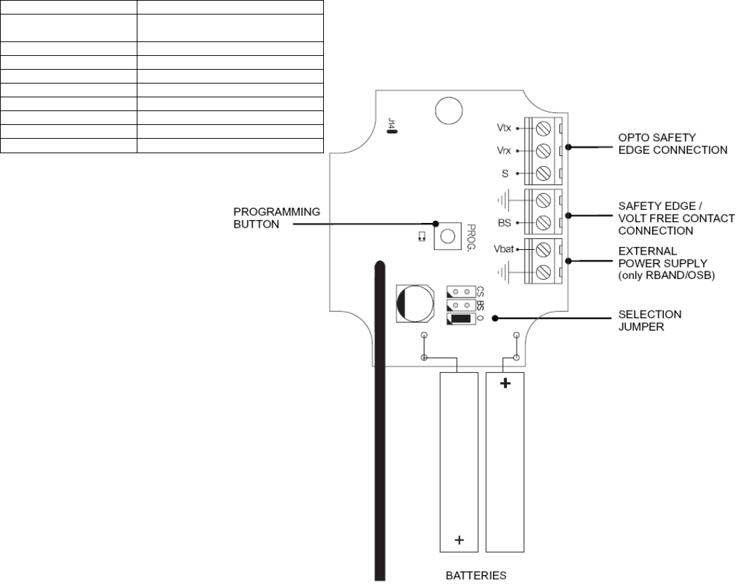
• INSTALLATION PROCEDURE AND BASIC WIRING
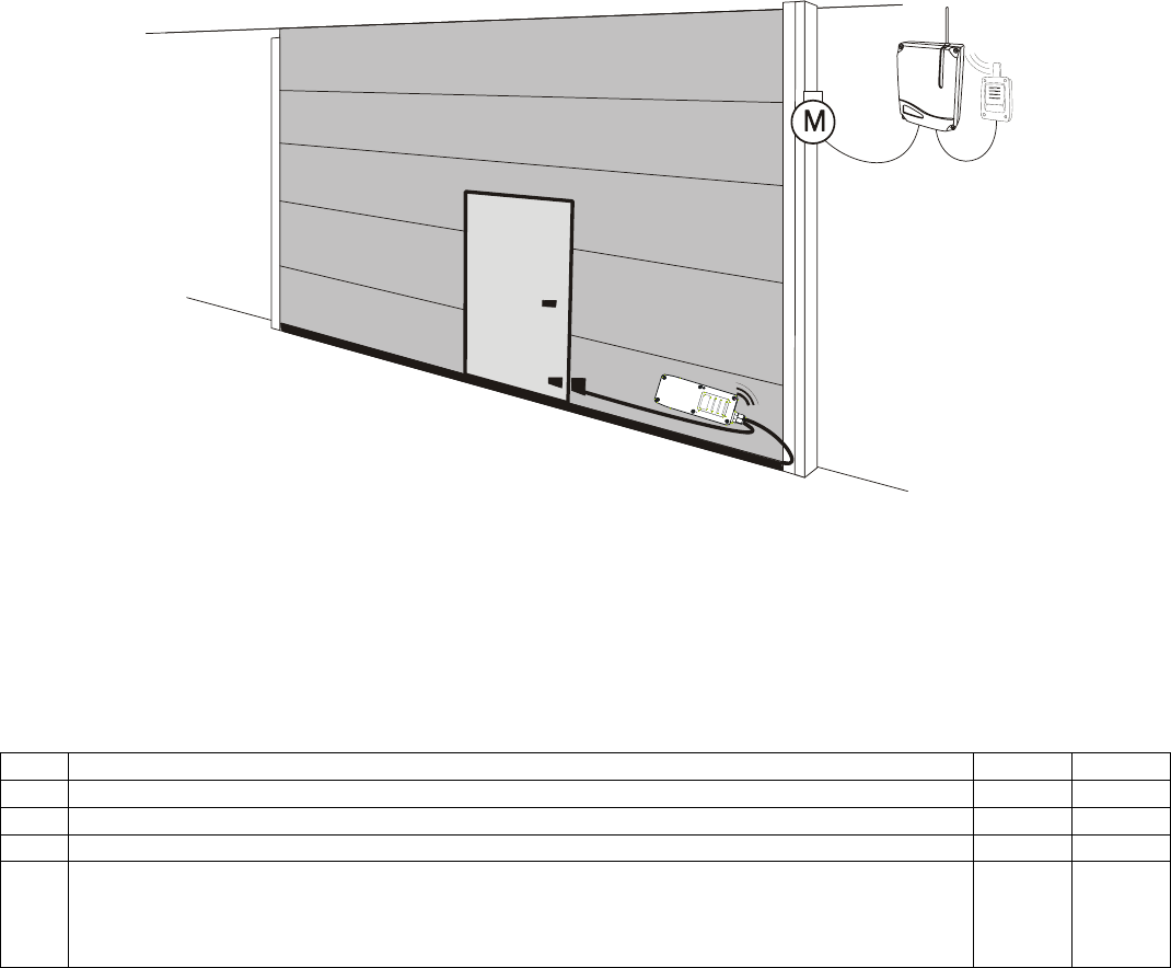
MECHANICAL INSTALLATION
Fix the back of the box to the door. Install the transmitter following the technical manual and avoid placing metallic surfaces
between the receiver and the transmitter. Pass the cables through the bottom of the transmitter. Connect the safety edge
following the electrical connections clause and ensure that the safety edge keeps totally waterproof. Fix the front of the
transmitter to the back with the screws supplied for the purpose.
SELECTOR JUMPERS
Allow selecting the type of the security element which is connected.
Jumper selector Function
CS Voltage free safety contact
BS 8k2 monitored safety edge
O Opto safety edge
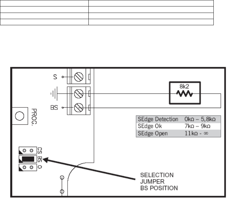
8k2 MONITORED SAFETY EDGE
Ensure the safety edge selection jumper is fitted in the BS position.
Electromechanical safety edges with 8k2 output are also considered 8k2 monitored safety edges.
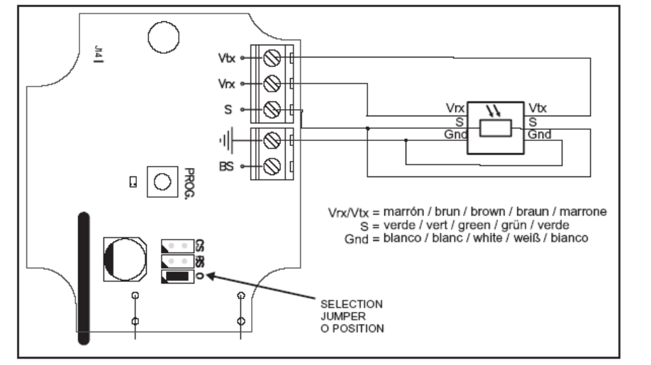
OPTO SAFETY EDGES
The use of opto safety edges requires the autotest signal or the current detector signal from the receiver.
Ensure the safety edge selection jumper is fitted in the O position.
The system is only compatible with low power opto transmitter/receiver (3Vdc / 3mA).
The opto safety edge remains in standby mode (non functioning) until it receives an activation signal from the receiver. The
activation signal is sent during the auto-test and it enables the opto safety edge for 60 seconds (by default) to allow the full
travel of the door/gate.
When using the current detector signal instead of autotest, the opto safety edge will remain active during the motor
movement.
COD. 1248034-GB / 1.1
RBAND/OS – RBAND/OSB
- 3 -
The activation time of the opto safety edge can be modified. Before doing this operation it is necessary to know the door
travel time.
1. Press the receiver PROG and CHECK buttons simultaneously until the three CHECK, B1 and B2 leds go light on.
2. Press the PROG button to begin the memorisation of the time the opto safety edge will be activated. You will hear a
beep each second, to count the time easier.
3. Press the PROG button another time to memorise the total time the opto safety edge will be activated.
4. Program the transmitter to the receiver again (see paragraph PROGRAMMING).
CONNECTION OF THE VOLTAGE FREE CONTACT
When a voltage free contact is to be connected, (eg. photocells or electromechanical safety edges without resistive output),
fit the jumper in CS position.
Note: In order to comply with the EN 12453 safety standard for the use of motorized garage doors, the device connected
to this input must have some verification system to ensure its proper functioning.
COD. 1248034-GB / 1.1
RBAND/OS – RBAND/OSB
- 4 -
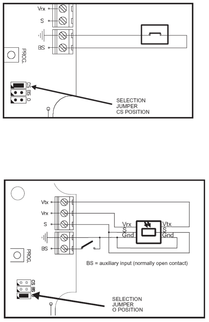
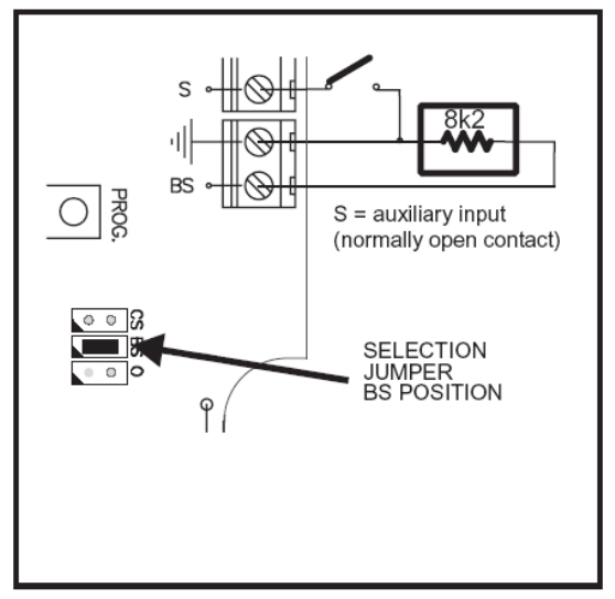
CONNECTING AN AUXILIARY INPUT
When programming in the receiver the Mode 4 (See PROGRAMMATION clause), an auxiliary input turns available on the
transmitter. The transmitter transmits the status of auxiliary input to the second relay of the receiver. This auxiliary input is a
normally open contact and it will be programmed always in the relay 2 of the receiver.
In case of using an 8k2 monitored safety edge or a voltage free safety contact, this auxiliary input will be on the S terminal.
In case of using an opto safety edge, this auxiliary input will be on the BS terminal.
Example of auxiliary input NO
COD. 1248034-GB / 1.1
RBAND/OS – RBAND/OSB
- 5 -
COD. 1248034-GB / 1.1
RBAND/OS – RBAND/OSB
- 6 -
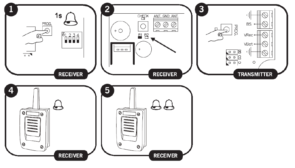
• PROGRAMMATION
Each safety edge transmitter must be learnt into the appropriate channel of the safety edge receiver.
Mode Configuration of transmitter programming in the receiver. Led R1 Led R2
1 By pressing the transmitter, relay 1 on the receiver will be activated
ON OFF
2 By pressing the transmitter, relay 2 on the receiver will be activated OFF ON
3 By pressing the transmitter, the two relays will be activated at the same time ON ON
4 The relays are activated 1st relay by channel 1 (operate as normal operation for connecting a
safety element) and 2nd relay by channel 2 (connection of an auxiliary input, the sender
transmits the status of the auxiliary input to the second relay of the receiver) (operates as a
normally open contact for connecting an auxiliary input)
Flashing
Flashing
Notes:
- Modes 1, 2 and 3: Up to 6 transmitters (3 on output R1 and 3 on output R2) can be connected to the receiver in modes
1, 2 and 3.
- Mode 4: In this mode only 3 transmitters can be connected to the receiver. The second relay cannot make the function
of indicating low battery.
- Each transmitter can be configured independently on the receiver.
- A Transmitter should only be connected to one receiver.
COD. 1248034-GB / 1.1
RBAND/OS – RBAND/OSB
- 7 -
If 10 seconds pass without programming a transmitter, the receiver will exit the programming mode.
If when programming a transmitter the receiver’s memory is full then it will emit 7 beeps of 0.5 sec and exit the
programming mode.
• MAINTENANCE
TRANSMITTER BATTERY LOW INDICATOR
If the battery of a transmitter programmed into the receiver becomes low, the receiver will beep 4 times every 20 seconds. If
there is more than one transmitter programmed, each safety edge should be activated to identify, hearing the 4 beeps, which
transmitter has a low battery. If the battery power is low, replace it immediately.
When the second relay of the receiver is not used for a safety edge, it can be used as a battery low indicator, useful to trigger
an alarm. It will activate the output relay when a transmitter with low battery is detected. In this case the receiver will not
indicate low battery with the beeps. Put dipswitch 4 on the function selector to ON.
Note: Only available in mode 1.
REPLACING THE TRANSMITTER BATTERY
Remove the box cover. Replace the two used batteries with new ones, taking into account the polarity indicated by the
connector. Check that the new batteries support the same temperature range as those they are replacing.
COD. 1248034-GB / 1.1
RBAND/OS – RBAND/OSB
- 8 -
IMPORTANT ANNEX
Disconnect the power supply whenever you proceed to the installation or repair of the control panel.
In accordance with the European low voltage directive, you are informed of the following requirements:
· For permanently connected equipment, an easily accessible connection device must be incorporated into the cabling.
· This system must only be installed by a qualified person that has experience with automatic doors/gates and knowledge of
the relevant EU standards.
· The instructions for use of this equipment must always remain in the possession of the user.
· Terminals with a maximum section of 3.8mm2 must be used to connect the cables.
· The frequency of the RadioBand system does not interfere in any way with the 868 MHz remote control systems.
JCM TECHNOLOGIES, S.A. declares herewith that the product RBAND/OS – RBAND/OSB complies with the requirements
of the 1999/5/ CEE R&TTE Directive, 2004/108/EC Directive on electromagnetic compatibility and 2006/95/EC on low
voltage, insofar as the product is used correctly.
This device complies with Part 15 of the FCC Rules. Operation is subject to the following two conditions: (1) this device may
not cause harmful interference, and (2) this device must accept any interference received, including interference that may
cause undesired operation.
To comply with FCC rules, adjustment or modifications of this receiver and/or transmitter are prohibited, except for changing
the code setting or replacing the battery. THERE ARE NO OTHER USER SERVICEABLE PARTS. Any other changes made,
not expressly approved by JCM Technologies, S A could void the user’s authority to operate the equipment.
CE CONFORMITY DECLARATION
See web www.motion-line.com