JCO Electronic Technology JCO40H H.265 WIFI User Manual
JCO Electronic Technology Co.,LTD H.265 WIFI Users Manual
UserManual.wiki
>
JCO Electronic Technology
>
JCO40H User Manual
User Manual
Navigation menu
Upload a User Manual
Namespaces
Wiki Guide
HTML
PDF
Info
Views
User Manual
Discussion / Help
Navigation
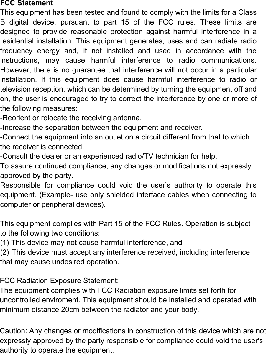
![Please read the guide or user manual carefully before usingNo. Name Description1 Bracket Support 3 axis adjustment2 Antenna Transfer and receive wireless signal3 Rear cover Rear cover of the case4 Front cover Front cover of the case5 Double loop glass Prevent inside light-leaking of lens6 Power supply DC 12V7 Ethernet port connect to Ethernet IP cable, 10/100M auto-adjustable8 Antenna interface Connect to IPC antennaWhen finished code matching, clickNo. Name Quantity No. Name Quantity1 Wireless NVR 1 7 Quick Operation Guide 12 Wireless IPC 4/8 8 Screw for hard disk 13IP Cable(1M) formatching code 1 9 Screw for IPC 4/84 USB Mouse 1 10 Power supply for NVR 15Antenna for NVR(black) 2 11 Power supply for IPC 4/86Antenna for IPC(white) 4/8 12 IPC installation sticker 4/812341096512 13 14 1518 21 221.Statement12341243① ⑦ ② ③④ ⑤ ⑥16Main menu →【System Setup】→ Recording Setting →【Backup】→ choose channel and time → select target file →【Backup】→ pull out mouse and insert backup device in 20s Attention: If target file can not be searched out, click 【clean】→【Add】. Please remove files which no need before backupping.Ensure insert device( like USB) in 20s,as system reserved searching time for it is 20s.IP CameraWire NetWireless NetScreen1PlaybackManual RecordSystem SetupImage ColorQuit2016-04-2 0 8:30:59System SetupRecor dDiskBacku pNum Nam e Residual/Rot al State1 /dev/sda1(usb) 28.76G/2 8.8 5G Id leQuitApplyDetec tionRemov eForma tUnins tallBacku p QueryQuitApplyBacku pRemov eDevic eRecor d TypeStart Tim eEnd TimeBacku pingcance l6 3 29 . 0 0M B/dev/s dc1(usb)All2016-0 4-20 8:00:00chann el AllcleanAddSize(K B)NumSystem SetupBacku pRec ord Set tings ,disk m anage ment, video f ile bac kup.nee d/rem ainin g space :2.30 G/28. 86GRec ord Set tings ,disk m anage ment, video f ile bac kup.1234Apr 2016SUN MON T UE W ED T HU F RI S AT1 2 3 4 56 7 8 9 10 11 1213 14 15 1 6 17 18 1920 21 23 24 25 2 627 28 29 3 0 3122Queryzoom inzoom outchannel01Manual Scheduie Motio n Alarm10:1 7:55 10 :22:5 5 10:27 :55 1 0: 32: 55 10:3 7:55 10 :42:5 5 10:47 :55channel02channel03channel04System SetupQuitChannelLocalAlarm Type Channel Enable Sensitivity 50Motion date 1Set Area Set TimeLinkage Screen RecordAllClean CopyApply√√Rec ord Set tings ,disk m anage ment, video f ile bac kup.Record SettingChann elPerio d123456Perio dPerio dPerio dPerio dPerio dPerio d1Wed Video type n ormal notion A lar m00:00: -23:5900:00: -23:5900:00: -23:5900:00: -23:5900:00: -23:5900:00: -23:59Defau lt Co pyBacku oDiskRecor dApply Q uitRecord Sett ings,disk man agem ent,video fil e backup.Stop video playback to Query√√ √ √Network SettingNet CardIP AddressSubnetGatewayMain NDSSub NDSMACDHCPNet Card1192.168. 0 .166255.255.255. 0192.168. 0. 1 8 . 8 . 8 . 8 8 . 8 . 8 . 4 00:00:01:02:03:08Default Save Refresh Cancel6. Repeater Function SettingWith latest repeater function, wireless NVR kit offer a new IPC signal connection type with further transmission distance , wider coverage area. IPC in further area can be connected to near IPC via WiFi signal and connect to NVR finally.Steps• Right-click to enter [Net Channel] interface, select [Repeater];• Click [+] to set bridging relationship.Net ChannelDev Has AddNum IP Addr Prot Protocol Co nnect Status RemoveRemove AllEdit DevDev Has SearchedAdd AllManual AddSet NVRMatch CodePRIVATE searchNum IP Addr Prot Prot Device123456789172.25.123 .4 554 Private Connecte d123456789 172.25.123 .3 554 Private 20:f4:1b:b a:5e:5dPepeaterModify IPNet ChannelDev Has AddRepeaterNVR Ch1Ch2Ch3Ch4Ch5Ch6Ch7Ch8++01020304Refresh SavePicture below shows 3 connect models • One by one: CH3→CH2→CH1→NVR• Two to one: CH5 and CH6→CH4→NVR• Directly connected to NVR: CH7→NVR,CH8→NVRDev Has AddNVR Ch1Ch4Ch2 Ch3Ch5Ch6Ch7Ch8++Refresh SaveRepeaterDelete • Click repeater to enter interface above→ put mouse in camera needed to delete→ left click→ delete→ save.• The camera which is deleted will connected to NVR automatically after 30S.2.Record and Playback① Check the hard disk. Click right button on main interface shows main menu, and chose 【System Setup】→ Record Setting → Disk. Make sure the hard disk is connected and runs normally. Attention : please format hard disk, it can come into use after showing capability.3. Backup7118iOS Android IP CameraWire NetWireless NetScreen1PlaybackManual RecordSystem SetupImage ColorQuitWireless NVR KitQuick Operation Guide4.Motion Detection Record 8.PC View 9.IE View17GMT 2016-7- 25 20:44:28 GMT 2016-7- 25 20:44:28① For logging in Danale for the first time, click to add device.IP CameraWire NetWireless NetScreen1PlaybackManual RecordSystem SetupImage ColorQuitSyetem SetupEnab leStat us Not onl ineDevi ce ID 6 44a20 35b 7c255 400 71d42 aP2PNetworkQuitAppl yPortRefr eshDevice ID APP Client√Network servicesIP CameraWire NetWireless NetScreen1PlaybackManual RecordSystem SetupImage ColorQuitNetwork SettingNet CardIP AddressSubnetGatewayMain NDSSub NDSMACDHCPNet Card1192.168. 0 .1 66255.255.2 55. 0192.168. 0. 1 8 . 8 . 8 . 8 8 . 8 . 8 . 4 00:00:01: 02:03:08Default Save Refresh Cancelck to a SettingSharing device19 2320② Timing and alarm record: Main Menu →【System Setup】 → Record Setting→ Record →chose channel and record type → apply. Users can click 【Copy】, copy to other channels with the same mode.Net ChannelDev Has AddNum IP Addr Prot PROTC OL Co nne ct St atus RemoveRemove AllEdit DevDev Has SearchedAdd AllManual AddSet NVRMatch CodePRIVATE searchNum IP Addr Prot Prot Device123456789192.168. 93. 212 8 0 Onv if Co nnected123456789 172.25.1 23. 3 554 P riv ate 20:f4:1b:ba:5e:5dRecord SettingChann elPerio d123456Perio dPerio dPerio dPerio dPerio dPerio d1Fri Vi deo type No rma l Motion Al arm00:00:- 23:5900:00:- 23:5900:00:- 23:5900:00:- 23:5900:00:- 23:5900:00:- 23:59Defau lt CopyBacku pDiskRecor dDefau lt CopyRecord Sett ings,disk managem ent,video file back up.Manual RecordChannel 1 2 3 4 5 6 7clearAll ReturnSave8IP CameraWire NetWireless NetScreen1PlaybackManual RecordSystem SetupImage ColorQuitchooseIP CameraWire NetWireless NetScreen1PlaybackManual RecordSystem SetupImage ColorQuitNetwork SettingNet CardIP AddressSubnetGatewayMain NDSSub NDSMACDHCPNet Card1192.168. 0 .166255.255.255. 0192.168. 0. 1 8 . 8 . 8 . 8 8 . 8 . 8 . 4 00:00:01:02:03:08Default Save Refresh CanceliOS Android 5.Internet Connecting7.Mobile Phone ViewWirelessNVRKitQuickOperation Guide12345678678](https://usermanual.wiki/JCO-Electronic-Technology/JCO40H/User-Guide-3869791-Page-1.png)