JDTECK JD60-7-TB-US Wireless Cellular Repeater User Manual User s manual
JDTECK INC Wireless Cellular Repeater User s manual
JDTECK >
Users Manual

JD60-7-TB-US
Wireless Cellular Repeater
User’s Manual

Wireless Cellular Repeater User Manual
- 2 -
1. SAFETY WARNINGS .....................................................................................................................................................3
2. WHY REPEATER............................................................................................................................................................4
2.1. REASON 1 .................................................................................................................................................................4
2.2. REASON 2 .................................................................................................................................................................4
3. INTRODUCTION.............................................................................................................................................................6
4. SYSTEM CHARACTERISTICS......................................................................................................................................7
4.1. FEATURES:..............................................................................................................................................................7
4.2. APPEARANCE OF THE TRIPLE BAND REPEATERS ...........................................................................................................7
5. BLOCK DIAGRAM AND WORK PRINCIPLE................................................................................................................8
6. THE REPEATER SYSTEM.............................................................................................................................................9
7. THE TRIPLE BAND REPEATER MAIN TECHNICAL SPECIFICATION.....................................................................10
7.1. MECHANICAL SPECIFICATION.....................................................................................................................................10
7.2. ENVIRONMENT CONDITIONS......................................................................................................................................10
7.3. RF TECHNICAL SPECIFICATION .................................................................................................................................. 11
7.4. REQUIREMENTS FOR ADAPTERS:............................................................................................................................12
7.5. REPEATER MODEL LIST ............................................................................................................................................13
8. INSTALLATION.............................................................................................................................................................14
8.1. INSTALLATION LOCATION REQUIREMENT ....................................................................................................................14
8.2. POWER REQUIREMENT .............................................................................................................................................14
8.3. INSTALLATION TOOLS AND ACCESSORY.......................................................................................................................14
8.4. INSTALLATION OF DONOR ANTENNA............................................................................................................................14
8.5. INDOOR ANTENNA INSTALLATION ....................................................................................................................................18
8.6 REPEATER INSTALLATION ...............................................................................................................................................19
8.4.1. Installation Steps............................................................................................................................................19
8.4.2. Repeater’s ports description ..........................................................................................................................21
8.4.3. Accessories selection.....................................................................................................................................21
8.5. REPEATER SETTINGS ...............................................................................................................................................22
8.5.1. Switch on power.............................................................................................................................................22
8.5.2. Manual Gain Control (MGC) ..........................................................................................................................23
8.5.3. GSM & DCS Band Settings............................................................................................................................24
8.5.4. WCDMA Band Settings..................................................................................................................................25
8.5.5. Adjusting System Isolation.............................................................................................................................27
8.5.6. Detecting Repeater ........................................................................................................................................28
8.6. SYSTEM TEST ..........................................................................................................................................................28
8.6.1. Check whether the coverage is good.............................................................................................................28
8.6.2. Repeater can not communicate in Power-ON status.....................................................................................29
9. HOT LINE.........................................................................................................................................错误!未定义书签。
Wireless Cellular Repeater User Manual
- 3 -
Preface
This user’s manual describes the installation, commissioning and maintenance of
JD60-7-TB-US Wireless Cellular Repeater.
Please do read the user manual carefully before installing and maintaining the triple band
repeater.
The information in this manual is subject to change without prior notice
Opinions are welcomed about the manual improvement.
1. Safety Warnings
Users must follow the below principles:
z Repeater should follow system requirement of communication equipment, assure good
groundings and lightning protection.
z The power supply voltage of repeater should meet the standards of security requirement; any
operation shall be carried out only after cutting off power in advance. Only the professional is
authorized for the operation.
z Do not dismantle machine, maintain or displace accessories by yourself, because in
this way, the equipment may be damaged or even get an electric shock.
z Do not open the repeater; touch the module of repeater, or to open the cover of
module to touch the electronic component, the components will be damaged due to
electrostatic.
z Please keep away from heating-equipment, because the repeater will dissipate heat during
operation. And do not cover repeater with anything that influences heat-dissipation.

Wireless Cellular Repeater User Manual
- 4 -
2. Why repeater
2.1. Reason 1
1) Blind or weak signal areas are formed if the buildings are too far away from BTS, or the buildings
themselves shield or absorb the signals.
2) There are too many complicated signals in the higher part of the buildings, therefore ping-pong switching
effect has been formed and the signals fluctuate a lot, there are annoying noises during phone calls and
there are dropped phone calls accordingly.
3) Elevators and basements are well-known blind areas.
4) Downtown areas of the cities, congested with many high-rise buildings are usually the weak or blind
areas.
2.2. Reason 2
The remote villages, mountains, hills, valleys, etc. are mostly scarcely populated areas with quite few mobile
users, so the main target is to send coverage to these areas, and it will not be cost effect to install a BTS tower,
therefore a repeater is a quite good option.
Can we not use mobile phones? The answer is definitely NO. But it might be much more miserable that the
communication can’t be achieved due to no or weak signals though there is a mobile phone.
Will your customers stay comfortable when there is no smooth communication in your shops or restaurants?
Will your business be influenced if your clients couldn’t call you through due to weak signals in offices?
Will your life be influenced if your mobile is always “out of service” at home when your friends call you?
How to solve the problems?
Best Solution:
Plug & play: Purchase a set of repeater solution and install it at your home, offices, and plug on the
power and immediately you would be able to enjoy the full bar and high quality signals!

Wireless Cellular Repeater User Manual
- 5 -
Question: Will repeater increase the RF radiation?
A: No, it will decrease instead.
As it can be searched easily through internet, the tower would “order” the mobile phone to increase its output
power, in order to ensure successful connection when the mobile signal bar is few, there will be stronger mobile
output power level when the mobile signal bar is less and the strongest one can reach 2W (GSM); moreover,
the mobile phone is usually as near as less than 5cm to human body when people are in phone calls. Not only
it influences badly the human bodies, but also run out of the battery power much more quickly; usually the
mobile phone gets hot in such status.
The maximum power level of JD60-7-TB-US is 0.01~0.1W, and it decreases to be maximum 0.003W when
reaching server antenna. And since the server antenna is installed over the ceiling or onto the wall, there are
usually more than 3 meter away from the human body, 3meter away means at least 40dB propagation loss, or
10000 times less, 0.0000003W, therefore it is too weak to influence human bodies though it is still a very good
signal for mobile phones.
And when a repeater is installed, it improves the mobile signals in the coverage, and the successful phone call
can be connected easily with a much less power level of the mobile phone, thus it will reduce tremendously the
RF radiation.
Wireless Cellular Repeater User Manual
- 6 -
3. Introduction
This JD60-7-TB-US full duplex mobile communications repeater from JDTECK INC is the perfect solution for
providing a wireless improvement in the cellular reception of a home, office, restaurant, VIP Room, apartment,
building or shopping mall, in the quickest time possible. One repeater covers 300 to 600 square meters.
It is designed to improve the call quality of an area by receiving, amplifying and re-transmitting signals of the
base station into a specified area via the server antenna of the repeater.
This repeater has Manual Gain Control (MGC) feature that enables engineers to reduce the gain of the repeater
manually if oscillation is detected or too strong input power level during installation, this will help to get the best
coverage effect without any interference back to mobile network.
And to maintain safe and specific output signal levels during the repeater’s operation, this repeater has a built-in
signal oscillation detection circuit to adjust the gain automatically so as to avoid interference to the cellular
network, also it gets color changing LED’s indicate its environmental status: the Alarm LED’s located on the front
of the unit (Alarm Low & Alarm High) will change color from green to orange or red, (depending on the input
power level) if the system detects signal oscillation in either band or, if the input signal is beyond a safe limit.
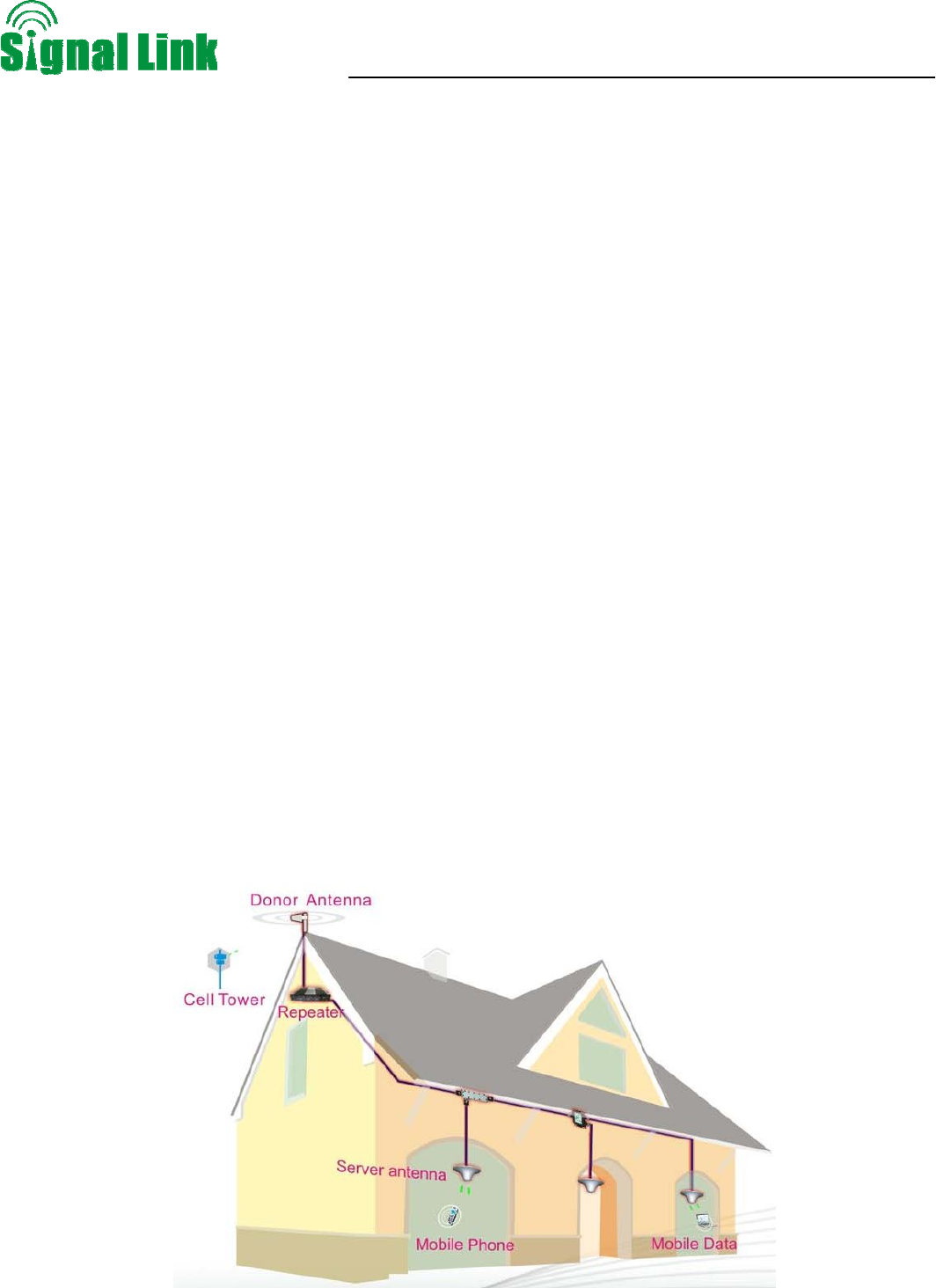
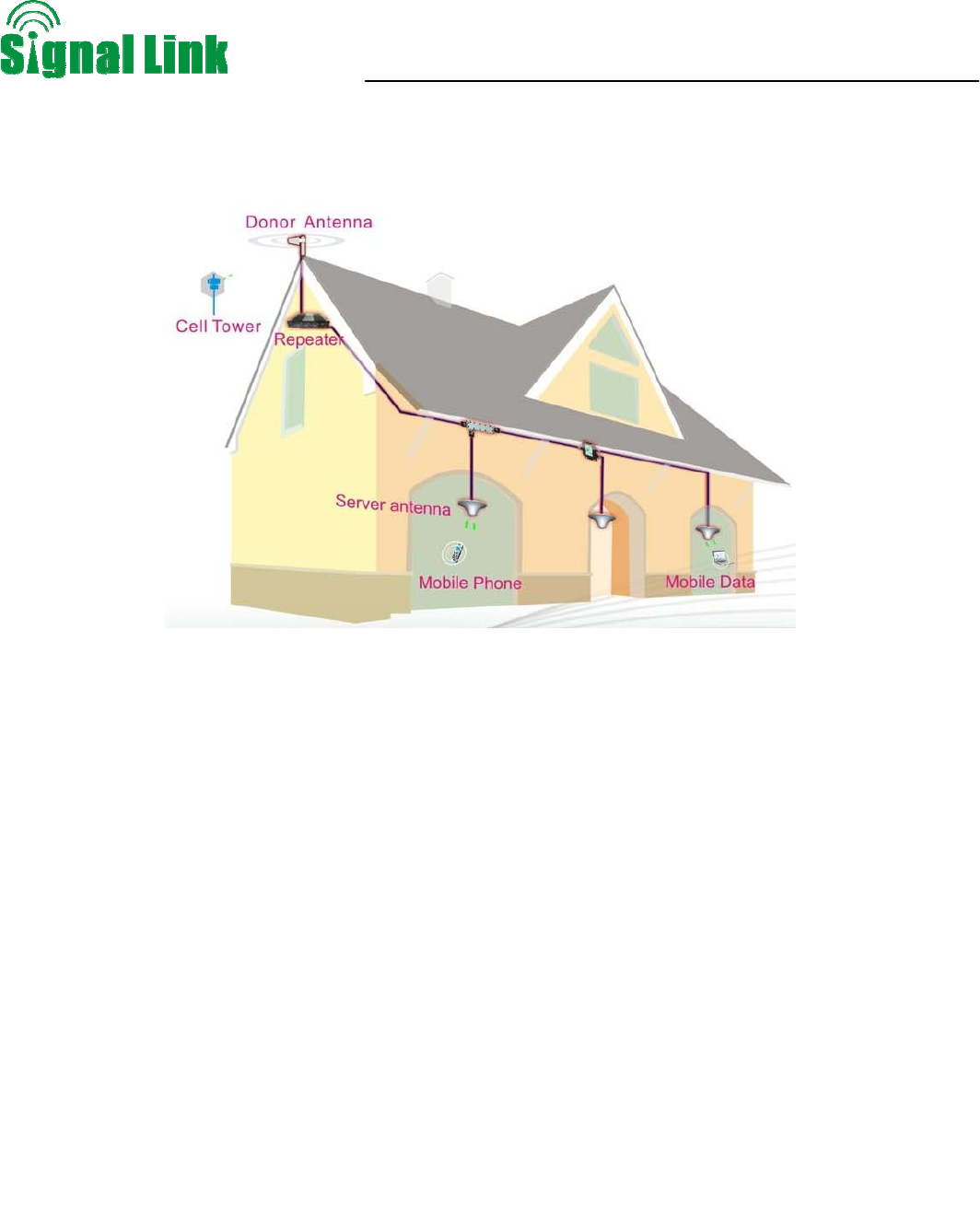
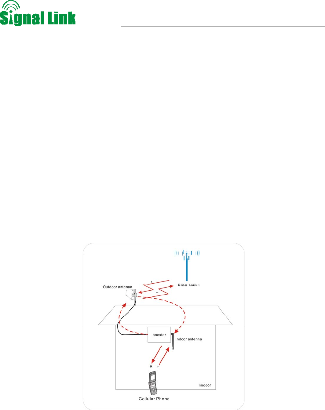
Below diagram shows how simple and fast repeater system is installed and works effectively: one wide band
directional antenna, as a donor antenna, has been installed at the top of the roof to pick up good mobile signals
from outside, and send through a 5D-FB cable to a JD60-7-TB-US repeater to be amplified significantly, then the
output signals are divided into three signals by a 8dB coupler and a 2way splitter, sent to three indoor omni
antennas and finally transmitted into the coverage area. Very clear phone call or high speed mobile data services
are immediately effected within the area.
Wireless Cellular Repeater User Manual
- 7 -
4. System Characteristics
4.1. Features:
z CE Certified
z Streamline shape
z Excellent out of band rejection.
z Wide power supply range and low power consumption
z High-integration (One board to contain low-noise amplifier, band pass filter, power amplifier module,
both uplink and downlink one for all)
z Wide band repeater to support all signals within three systems.
z Manual gain control provides a variety of applications.
z MTBF>50000h, low failure rate
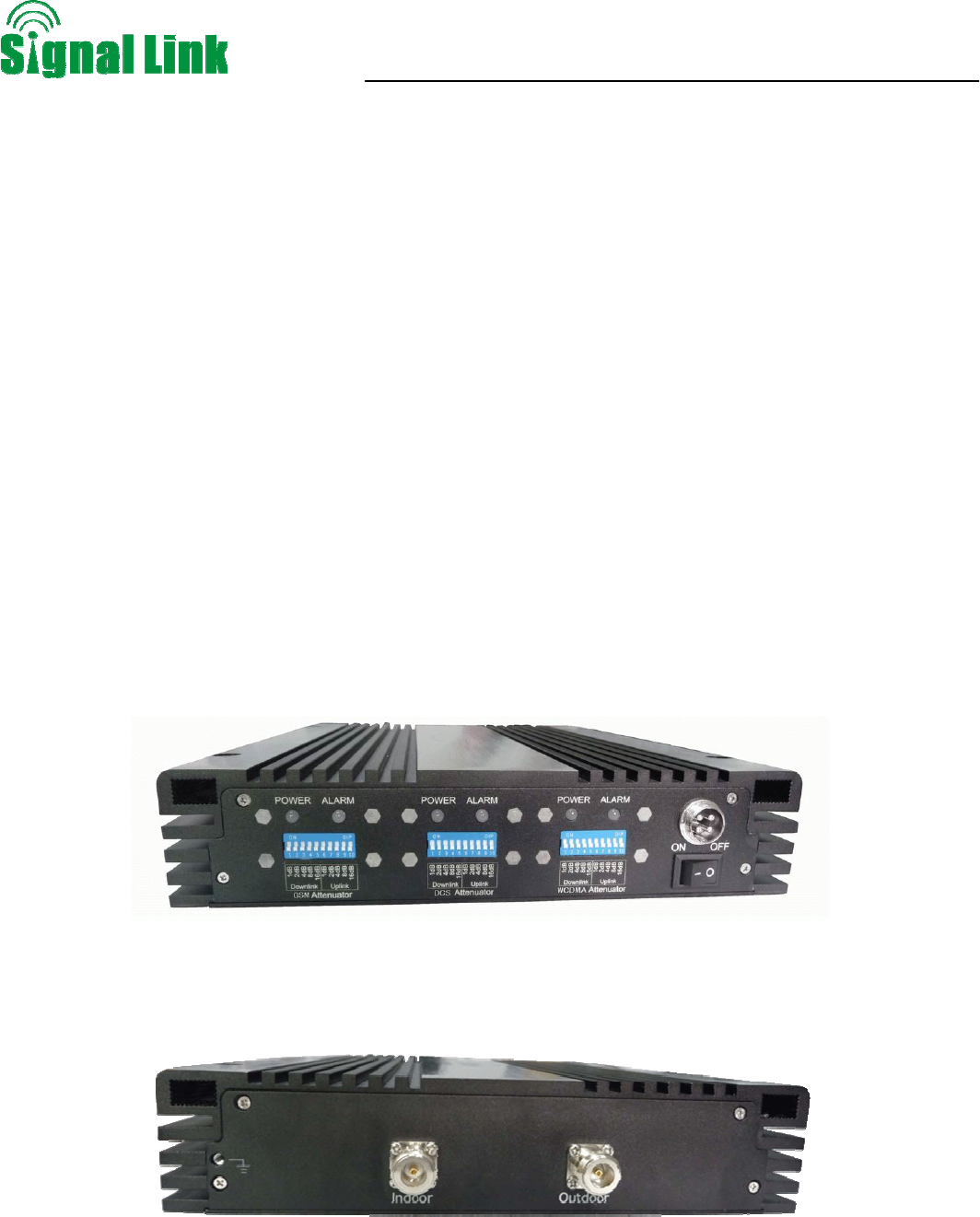
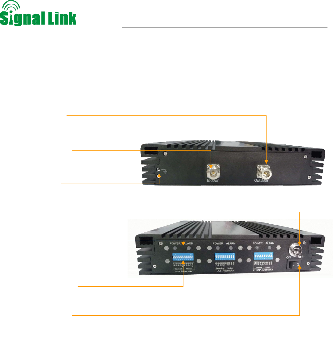
4.2. Appearance of the triple band repeaters
Figure 1 shows the front view (colors may differ from real products).
Figure 2 Front view of repeater
Wireless Cellular Repeater User Manual
- 8 -
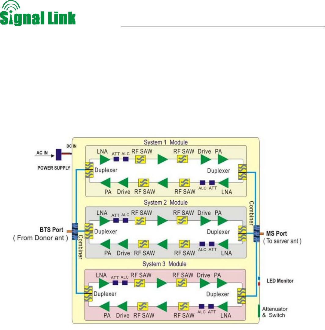
5. Block diagram and work principle
The triple band repeater is a bi-directional repeater that consists of three mobile systems, the three systems
are combined together by a combiner, and each system gets their independent uplink and downlink power
amplifying system, and each link consists of duplexer, LNA, Filter and PA. The triple band repeater downlink
receives, amplifiers and retransmits the signals over the air from BTS to the coverage area; at the same time,
the uplink receives, amplifies and retransmits the signals of MS back to BRS, therefore a successful
communication is accomplished.
Modules in the system diagram:
z Combiner: a combiner helps to combine signals of three mobile systems together, and at the same
time to keep independence of each system and avoid their interference of each other.
z Duplexer: The main purpose of duplexer is to combine downlink and uplink to share the same
antennas, the duplexer is composted of one pair of band pass filter that can not only reject the
spurious interference, but also increase the isolation of Uplink and Downlink
z LNA: LNA is the first active sub system of the repeater, of which low noise and high linearity is
requested under strong input signals. LNA is the major sub system that determines the noise figure
of the repeater system.
z PA: The power amplifier sub system helps the repeater to reach its targeted output power, linearity
of which decides the linearity of the repeater
z Power supply is to supply power electricity to all repeater’s modules
Wireless Cellular Repeater User Manual
- 9 -
6. The repeater system
z Donor Antenna:
¾ 5~7dbi outdoor panel or 7~9dBi wide band Yagi are recommended as donor antenna.
¾ Function: Pick up donor signals from the BTS and send to the repeater by cable; the received
signals’ power level and quality influence a lot on the coverage effect. Donor antenna also
transmit the uplink signals from the repeater to BTS.
z Server Antenna:
¾ 2~3dBi indoor omni ceiling or 5~7dBi indoor panel are recommended.
¾ Omni antenna (Indoor ceiling omni antenna or whip antenna), suitable to installed in the center
and radiate all direction; It is better to use a directional panel antenna or Yagi when the coverage
shape is long and narrow (corridors, long row of houses in two sides, tunnels or elevators or rural
open space)
z Cables: LMR 300 or 400, 5D or 8D –FB coax cables are recommended.
z Splitters or couplers: when the building structure is too complicated or there is big loss due to thick
walls, etc., splitters or couplers shall be used so that more antennas can be installed in more areas
to distribute the signals to each corner of the coverage area.
z Power Box including electricity meter, air switch and groundings, some sites might need surge
arrestors.
z Note: because this triple band repeater is a broadband repeater, so band in requirements contain
antenna, splitter and coupler in this system is 880-960MHz and 1710-2170MHz.
z This device complies with part 15 of the FCC Rules. Operation is subject to the following two
conditions: (1) This device may not cause harmful interference, and (2) this device must accept any
interference received, including interference that may cause undesired operation.
Wireless Cellular Repeater User Manual
- 10 -
z Changes or modifications not expressly approved by the party responsible for compliance could void
the user's authority to operate the equipment.
z This equipment complies with FCC radiation exposure limits set forth for uncontrolled
environment .This equipment should be installed and operated with minimum distance 400cm
between the radiator& your body.
7. The triple band repeater Main technical specification
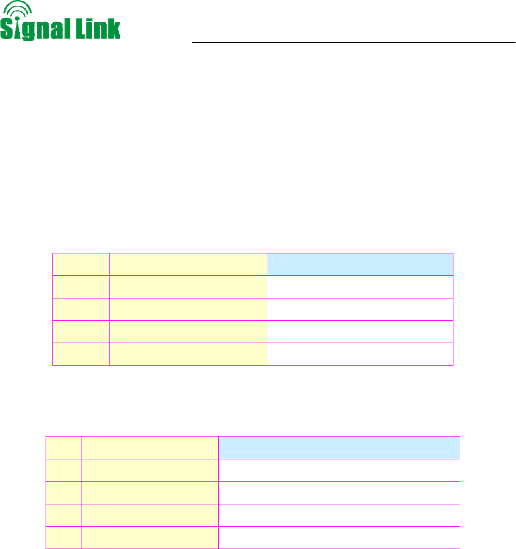
7.1. Mechanical specification
SN Item specification
1 Dimensions 250x 330 x 53 mm
2 Weight 4.5kg
3 Environment Conditions IP40
4 Cooling mode Nature cooling
7.2. Environment Conditions
SN Item specification
1 Operating Temperature -25°C to +55°C
2 Storage Temperature -40°C to +80°C
3 Humidity 5% to 85%
4 Air Pressure 86 kPa to 106 kPa
Wireless Cellular Repeater User Manual
- 11 -
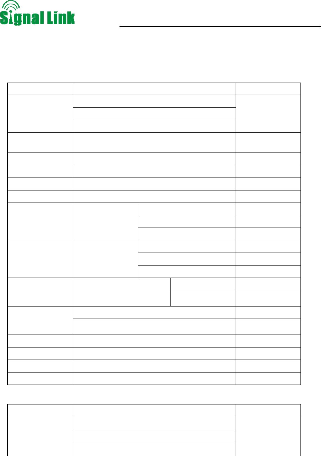
7.3. RF technical specification
NO:
Uplink
Test Project Test Condition Index Require
824~849MHz(GSM/CDMA)
1850~1910MHz(PCS/CDMA)
Frequency Range
1710~1755MHz(AWS)
Band Width GSM/CDMA:25MHz, PCS/CDMA:60MHz, AWS:
45MHz
Max .Gain Testing in working band(without control) 63±1dB
ALC Output Center frequency(deep control 10dB) 10±10dBm
ALC Center frequency(deep control 1~20dB) |△|≤2.0dB
AGC Center frequency, deep control 15~20dB(red) Shut off
CDMA ≤8dB
GSM/PCS ≤10dB
Gain Flatness Testing in working
band
AWS ≤6dB
1~10dB,1dB step |△|≤1.0dB
11~20dB,1dB step |△|≤1.5dB
Gain control error Center frequency
21~30dB,1dB step |△|≤2.0dB
9KHz~1GHz ≤-36dBm
Intermodulation
Center frequency, double
audio signal interval 600KHz
(deep control 10dB) 1GHz~12.75GHz ≤-30dBm
9KHz~1GHz ≤-36dBm
Spurious Emission
Output
inter-modulation 1GHz~12.75GHz ≤-30dBm
Input V.S.W.R Testing in working band ≤ 3.0
Output V.S.W.R Testing in working band ≤ 3.0
Group Delay Testing in working band ≤ 0.5us
Noise Figure Testing in working band(Max gain) ≤ 8dB
Downlink
Test Project Test Condition Index Require
869~894MHz(GSM/CDMA)
1930~1990MHz(PCS/CDMA)
Frequency Range
2110~2155MHz(AWS)
Wireless Cellular Repeater User Manual
- 12 -
Band Width GSM/CDMA:25MHz, PCS/CDMA:60MHz, AWS:
45MHz
Max .Gain Testing in working band(without control) 67±1dB
ALC Output Center frequency(deep control 10dB) 15±10dBm
ALC Center frequency, deep control 1~20dB |△|≤2.0dB
ALC deep control 1~5dB Orange
AGC
Center frequency
deep control 15~20dB red and shut off
CDMA ≤8dB
GSM/PCS ≤10dB
Gain Flatness Testing in working
band
AWS ≤6dB
1~10dB,1dB step |△|≤1.0dB
11~20dB,1dB step |△|≤1.5dB
Gain control error Center frequency
21~30dB,1dB step |△|≤2.0dB
9KHz~1GHz ≤-36dBm
Intermodulation
Center frequency, double
audio signal interval 600KHz
(deep control 10dB) 1GHz~12.75GHz ≤-30dBm
9KHz~1GHz ≤-36dBm
Spurious Emission
Output
inter-modulation 1GHz~12.75GHz ≤-30dBm
Input V.S.W.R Testing in working band ≤ 3.0
Output V.S.W.R Testing in working band ≤ 3.0
Group Delay Testing in working band ≤ 0.5us
Noise Figure Testing in working band(Max gain) ≤ 8dB
Remark:
1,Power supply 12V/5A
2,Shut off function, about 5 second
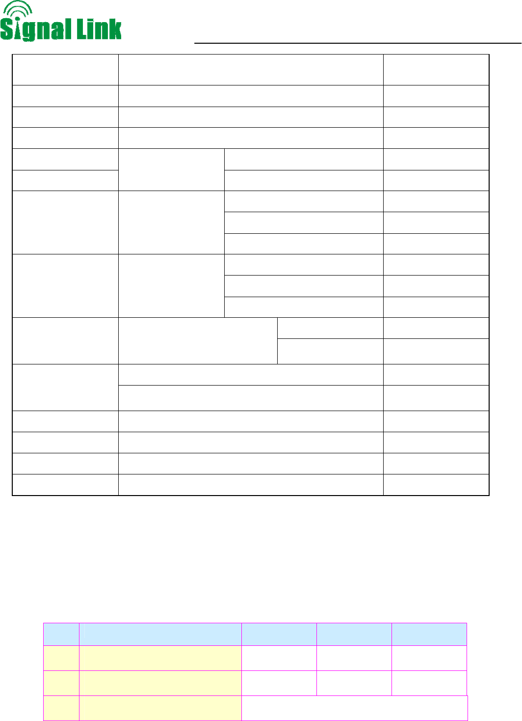
7.4. Requirements for adapters:
SN Item Minimum Typical value Maximum
1 Input Voltage Range 100 V 220 V 264 V
2 Output Voltage Range 47 Hz 50Hz 63 Hz
3 Total Power Consumption 50W
Wireless Cellular Repeater User Manual
- 13 -
7.5. Repeater Model List
MODEL NO:JD60-7-TB-US -GDW
Device Type F: Wide band consumer repeater
Power rating
10: downlink output power is 10dBm
15: downlink output power is 15dBm
20: downlink output power is 20dBm
C: GSM850 or CDMA800
P: PCS or CDMA1900
A: WCDMA1710-2155
CP: dual band C (GSM850 or CDMA800) & P (PCS or CDMA1900)
System code
CPA: Triple band C (GSM850 or CDMA800) & P(PCS or CDMA1900) &
A (WCDMA1710-2155)
Device Type
Power rating
System code
Wireless Cellular Repeater User Manual
- 14 -
8. Installation
The triple band repeater micro repeater should be used to cover the area indoor and the humidity and
temperature of working can affect the reliability of repeater. So, temperature, humidity, dust, interference, power,
space requirements and other factors should be considered during installation of repeater.
8.4. Installation Location Requirement
1) It is appreciated that the repeater is installed in a cool, dry and ventilated room without erosive gas and
smoke and without leakage on its proof.
2) Besides above, a cool and ventilated wall of which sun-proof and waterproof is expected.
3) Besides above, common wall, tower or high pole is ok.
4) Installation height should be easy for RF cable wiring, heat dissipation, security and maintenance.
5) Have a set of independent and stable power supply.
6) Have lightning conducer in the building, tower or high pole with enough strength or stability.
8.5. Power requirement
Generally it is AC power supply,and the requirement of AC is 100~264VAC/50±5Hz
8.6. Installation tools and accessory
No. Name Specification Quantity Remark
1 Plastic Expansion Bolt M5*24 6 Standard accessories
2 Tapping screw M3*27 4
Standard accessories
3 reciprocating drill 1
Engineering-owned, punch the
wall
4 Shot bit M3 1 Engineering-owned, punch the
wall
8.7. Installation of donor antenna
The repeater’s main function is to improve weak RF signals to an area. A simple formula: Input power+ Gain=
Output power. The signal strength from the outdoor antenna directly affects the efficiency of the indoor coverage.
It is very important to choose the location of the outdoor antenna carefully. With this in mind, it is not
Wireless Cellular Repeater User Manual
- 15 -
recommended the donor antenna to be installed in an attic.
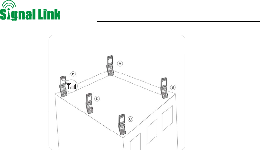
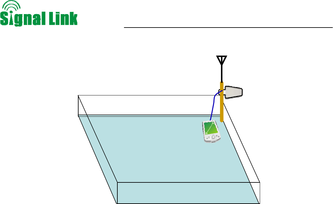
Testing the signal strength received from donor antenna mounted in site by mobile phone:
z Please select the top of the building to install the donor antenna if the total floors are less than 7,
and must select a place like balcony or platform lower than 7th floor for the donor antenna if the
buildings are over 7 floors.
z The mobile phone shall display full bar signals in location where the donor antenna is installed
z The phone calls or data transmission are smooth and stable by 3 times testing in location where
the donor antenna is to be installed
z As shown from the above illustration, testing the signals from A to E, and select a best place that
displays full bar signals to install the donor antenna.
Selection the installation direction of donor antenna
z The donor antenna shall point to the direction of the tower, and it would be much better to keep
line of sight.
z Please select the opposite directions for donor antenna and server antenna. If donor and server
antennas have to be installed in the same direction, please install them only after the signal
quality is tested and the self-oscillation is avoided. If the directional antenna is selected, the
main directional angle should point to the tower antenna.
z If the performance is poor due to weak signals or poor phone call quality after installation, please
adjust the direction of donor antenna or change its installation position in order to obtain the best
calling effect.
Donor antenna installation ---Notes:
z Do not install the donor antenna during the rainy day with lightning.
z Please follow the instructions to install the donor antenna.
z It is a must that the waterproof shall be done to connectors of donor antenna and feeder lines.
z In order to avoid interference, please note that the donor antenna should be far away from the
Wireless Cellular Repeater User Manual
- 16 -
following objects.
Metal
High-voltage line
RF antenna
High-voltage transformer
z Repeater is a two-way signal amplifier. So proper isolation between donor antenna and server
antenna is necessary in order to avoid self-oscillation. About the definition for self-oscillation,
take MIC and loudspeaker for example; if it is too close for each other, it could make big noise.
So the repeater can run smoothly if the isolation between donor antenna and server antenna is
15 dB higher than the gain of booster. For example, if the booster gain is 60 dB, then the
isolation between donor antenna and server antenna should be 75 decibel.
The minimum distance between donor antenna and server antenna is 10 meters, again the
direction of donor and server antennas shall be opposite.
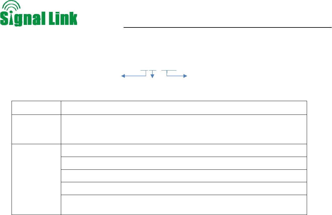
As shown in the below illustration, the booster amplifies the signal R and signal T from the tower
at the same time. If the distance between donor antenna and server antenna is less than the
required distance, then the amplified signal R (T) will back to server antenna (donor antenna). So
it will lead to self-oscillation and reduce the coverage area, also the bad calling quality could
happen at the same time.
If isolation can’t be achieved by the limited distance, the roof of the building or other barriers can
be used to increase isolation.
Wireless Cellular Repeater User Manual
- 17 -
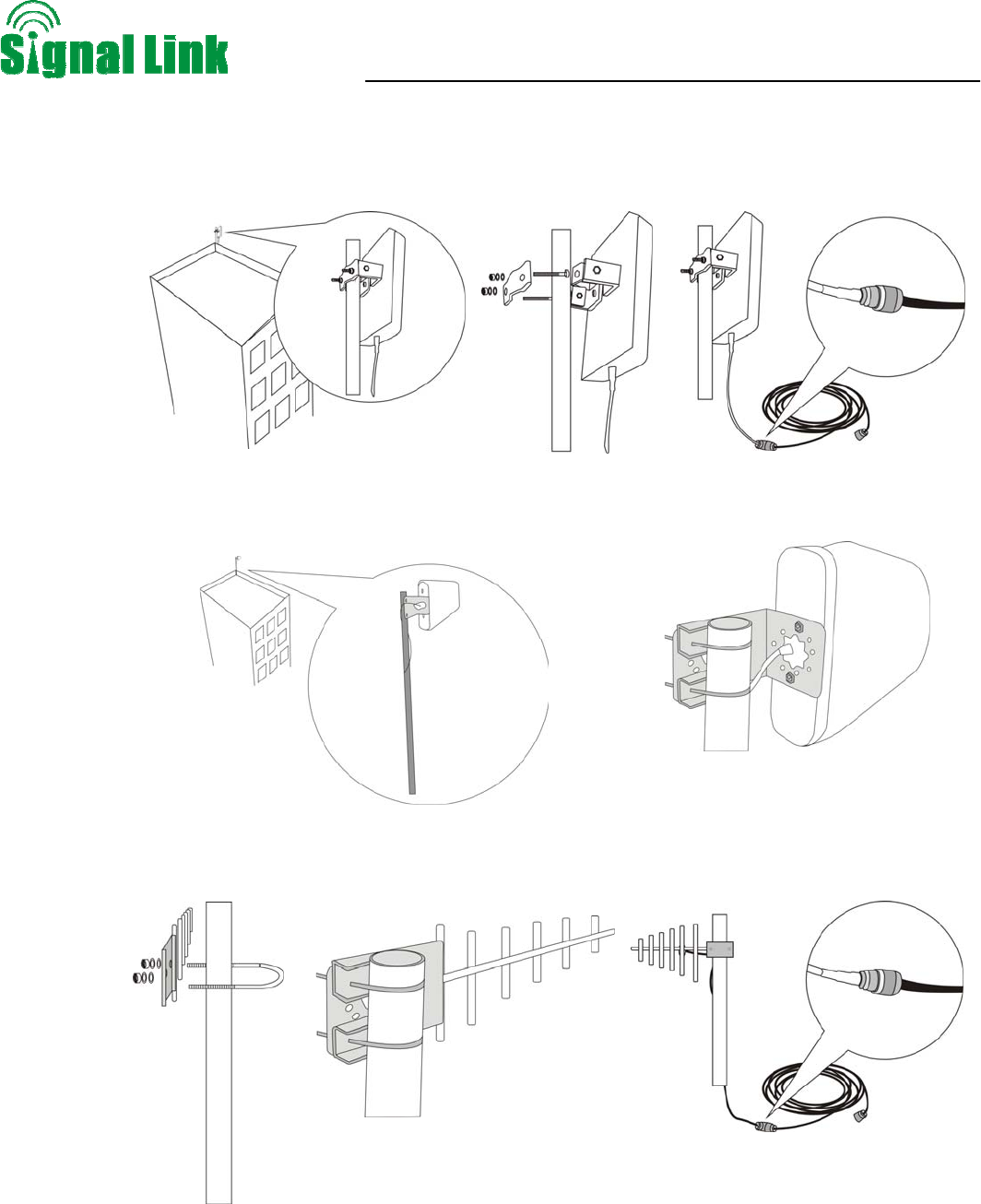
Installation of panel antenna as donor antenna
Installation of wide directional antenna as donor antenna
Installation of YAGI antenna as donor antenna
Wireless Cellular Repeater User Manual
- 18 -
Test the call quality of donor antenna
Fix the donor antenna after selecting the best position, and adjust slightly its height or angles in
order to get the signals with suitable input power level and calling Quality
z System Requirement of GSM or DCS
1) The total input power level shall be around -50dBm, lowest shall be more than –80dBm
2) Test by mobile phone or data card by 3~5 times to make sure the calling quality is good
in 95% of the time, and no handovers.
3) It is requested that the leading BCCH shall be 6dBi higher than the second (for
professional engineering reference only).
z System Requirement of WCDMA
1) The total input power level shall be around -50dBm, lowest shall be more than –70dBm
2) Test by mobile phone or data card by 3~5 times to make sure Ec/Io is more than –7dB,
and no handovers.
3) Ec/Io of adjacent carrier shall be 8dB less than that of donor carrier to avoid soft
handover. The active PN shall be only 1.
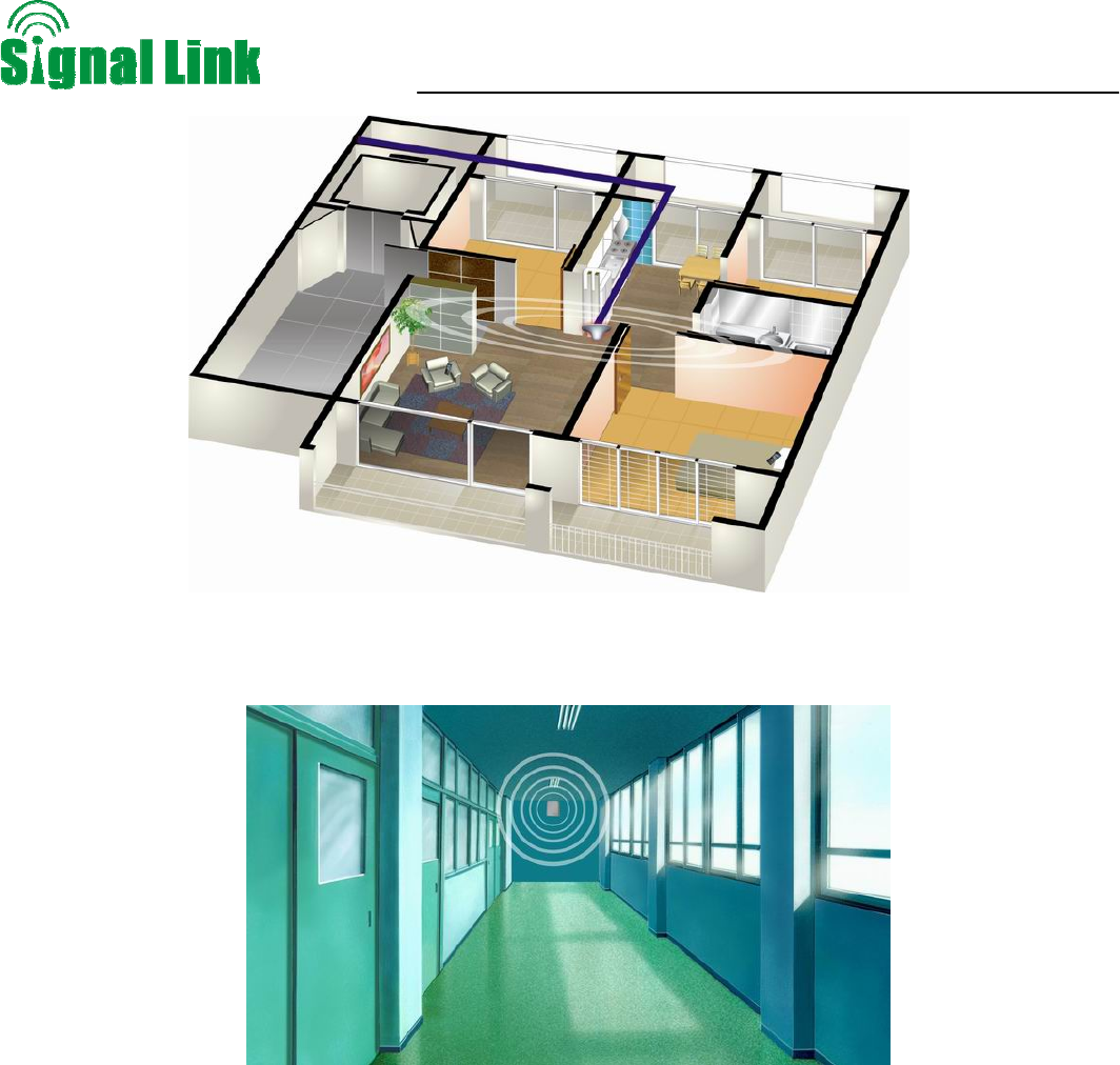
8.5. Indoor antenna installation
Proper antennas shall be selected according to the site conditions and the requirement.
Omni antenna (Indoor ceiling omni antenna or whip antenna), suitable to installed in the center and radiate all
directions
Lightening
Test Engineer Phone
Wireless Cellular Repeater User Manual
- 19 -
It is better to use a directional panel antenna or Yagi when the coverage shape is long and narrow (corridors,
long row of houses in two sides, tunnels or elevators or rural open space)
8.6 Repeater Installation
8.7.1. Installation Steps
The triple band repeater shall be installed in indoor areas only
Drill holes on the selected place and install expansion bolts.
Align the holes on the installing support with the expansion bolts, keep the installing support vertical, place
flat washers, spring washers, and nuts in turn, and tighten the nuts to fasten the installing support.
Place the repeater on the support and fasten it.
Connect cables and power cables to the repeater respectively.
Wireless Cellular Repeater User Manual
- 20 -
After installing the repeater as described as above, power on the repeater to check the operation status.
Wireless Cellular Repeater User Manual
- 21 -
8.7.2. Repeater’s ports description
Outdoor port: connected with the donor antenna by cable
Indoor port: connected with server antenna directly or by cable
DC IN: connected with power supply.
Note: The indicator LED and DIP Switch attenuation in the three system above,from left to right,
respectively is GSM, DCS and WCDMA .
8.7.3. Accessories selection
Please pay attention to the two points of “frequency” and “impedance” during the selection of the accessories.
All accessories shall support the repeater’s frequencies from feeder line, antenna and splitter to combiners etc.
For example, the repeater’s frequency is GSM900+DCS1800+WCDMA, so all the accessories must support the
890MHz~2170MHz frequency. And the repeater’s impedance is 50ohm, so the accessories shall all be 50ohm.
To use any other impedance of coax will put an extra load on your repeater, shorten its life span and decrease
the system performance.
Power adaptor
DC in
Outdoor port:
Connect the Donor
Antenna
Power Indicator LED
Indoor port: Connect
the Sever Antenna
Grounding
DIP Switch attenuation
Power ON/OFF
Wireless Cellular Repeater User Manual
- 22 -
8.8. Repeater Settings
Please check very carefully all cable connections are correct and firm before running operation test and then
carry out following tests
8.8.1. Switch on power
After power is on, check firstly the alarm and power LEDs.
z Status and definition of POWER indicators:
z Status and Definition of ALARM indicators,
Status ALARM
It is working in linearity
Green
attention: Input signals may be not enough
Red There are overloading or self oscillation, strong input signals, measures shall
be taken
It is working in linearity
Orange Attention: Please adjust MGC to increase the attenuation value, till you find the
“edge point” ( I.E. the Alarm LED shall stay at green color, with intention of
turning Orange), and let the repeater work at this point.
Off Repeater break down
Remark:
Please note that Alarm LED works on repeater downlink signals only, I.E. the repeater input signals
from BTS.
Status Definition
Green Normal
Off DC power problem
Wireless Cellular Repeater User Manual
- 23 -
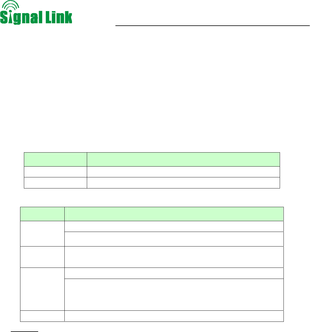
8.8.2. Manual Gain Control (MGC)
z Note: GSM as example, the rest two system is the same as GSM.
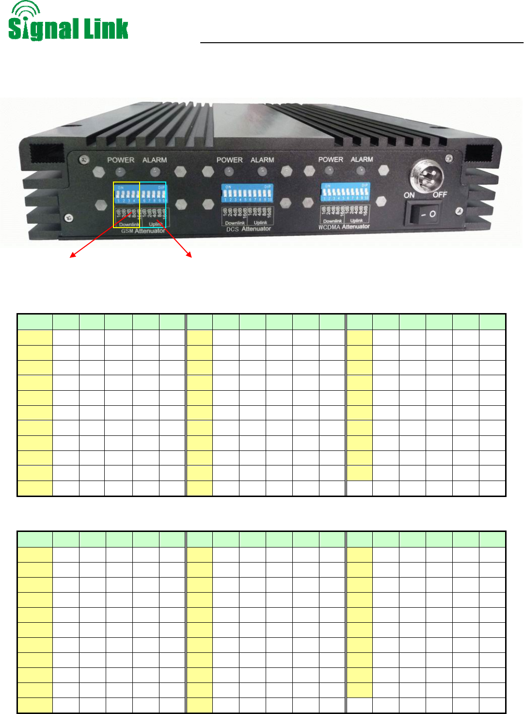
z DIP switch uplink attenuation setting:
Att 1 2 3 4 5 Att. 1 2 3 4 5 Att. 1 2 3 4 5
0 dB off off off off off 11dB ON ON off ON off 22dB off ON ON off ON
1 dB ON off off off off 12dB off off ON ON off 23dB ON ON ON off ON
2 dB off ON off off off 13dB ON off ON ON off 24dB off off off ON ON
3 dB ON ON off off off 14dB off ON ON ON off 25dB ON off off ON ON
4 dB off off ON off off 15dB ON ON ON ON off 26dB off ON off ON ON
5 dB ON off ON off off 16dB off off off off ON 27dB ON ON off ON ON
6 dB off ON ON off off 17dB ON off off off ON 28dB off off ON ON ON
7 dB ON ON ON off off 18dB off ON off off ON 29dB ON off ON ON ON
8 dB off off off ON off 19dB ON ON off off ON 30dB off ON ON ON ON
9 dB ON off off ON off 20dB off off ON off ON 31dB ON ON ON ON ON
10 dB off ON off ON off 21dB ON off ON off ON
z DIP switch downlink attenuation setting:
Att 6 7 8 9 10 Att. 6 7 8 9 10 Att. 6 7 8 9 10
0 dB off off off off off 11dB ON ON off ON off 22dB off ON ON off ON
1 dB ON off off off off 12dB off off ON ON off 23dB ON ON ON off ON
2 dB off ON off off off 13dB ON off ON ON off 24dB off off off ON ON
3 dB ON ON off off off 14dB off ON ON ON off 25dB ON off off ON ON
4 dB off off ON off off 15dB ON ON ON ON off 26dB off ON off ON ON
5 dB ON off ON off off 16dB off off off off ON 27dB ON ON off ON ON
6 dB off ON ON off off 17dB ON off off off ON 28dB off off ON ON ON
7 dB ON ON ON off off 18dB off ON off off ON 29dB ON off ON ON ON
8 dB off off off ON off 19dB ON ON off off ON 30dB off ON ON ON ON
9 dB ON off off ON off 20dB off off ON off ON 31dB ON ON ON ON ON
10 dB off ON off ON off 21dB ON off ON off ON
DIP Switch attenuation
Uplink attenuation Downlink attenuation
Wireless Cellular Repeater User Manual
- 24 -
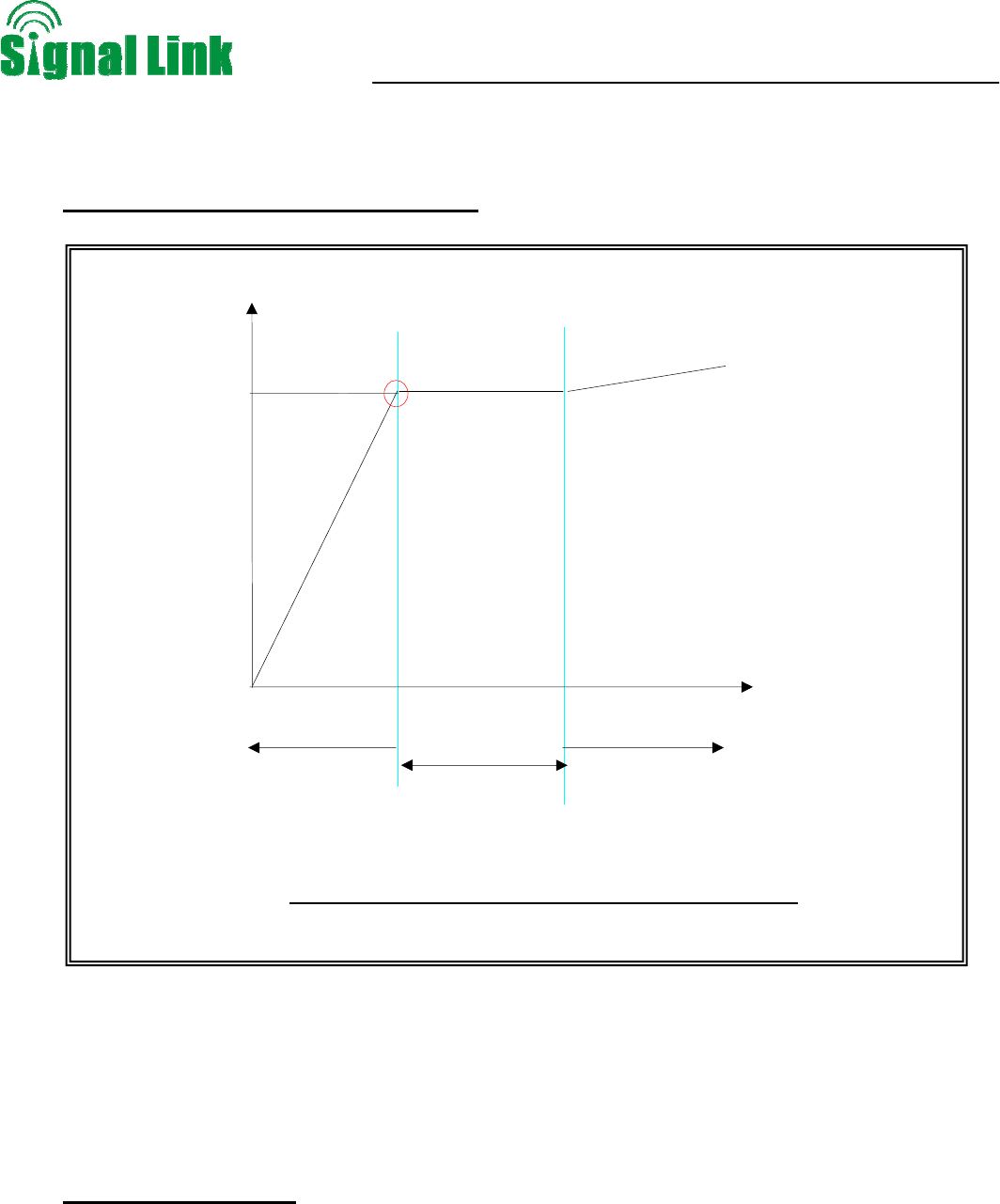
8.8.3. GSM & DCS Band Settings
z The curve about device working status
POutput Power: Output Power
Pinput Power: Input Power
VATT: Attenuation value of attenuator
Pinput Power -VATT: Input Power-Attenuation value of attenuator
Pmax: Rate output power
z Downlink gain setting
First the alarm LED only indicates the downlink input power level, here we use color of Alarm LED
to adjust the gain of the repeater. As for the downlink working performance, Alarm LED of “Green”
color and with the intention of turning orange is a good working point, here we refer as “edge point”. At this
time, downlink output power and coverage effect are stable.
And the equipment must be as far as possible away from overloading status of “red” (tthe equipment would
hold higher interference and depression ability at this stage). So we try our best to set the equipment near
POutput Power
Pmax
(Pinput Power-VATT)
Green LED linear
amplification area
Red LED Equipment
overload zone
Orange LED
Stable work area
Critical stable point
Output power, input signal and their attenuation curve
Wireless Cellular Repeater User Manual
- 25 -
“edge point” of green and intention of turning orange during engineering.
z Setting of “edge point”:
Switch on the power supply after connection with donor antenna and server antenna, and observe
ALARM LED.
If it shines “orange”, use 1dB as step to reduce the gain until “green” turns on, then increase the gain
1~3dB attenuation value until “orange” starts to turn on, then brings back 1~2dB till “green” is on, then
fix the gain and the repeater’s downlink output power reaches the perfect status.
If it shines “green” then,
To check whether the attenuation value has been set, if it is, use 1dB as step to increase gain until
the “orange” turns on, then brings back 1~2dB till “green” is on again , then the repeater’s downlink
output power reaches the perfect status.
But if attenuation is not set, it indicates that the input power is not enough.
Then please check coverage effect first, if the coverage effect is good, the engineering has
reached expecting target
But if the coverage effect is not good, the donor antenna should be adjusted to get a stronger
signals until “orange” intends to turn on or the effect reaches the target. At this stage, please
make sure “Orange” color is not generated by self oscillation. Please take off the server
antenna to test if it is self oscillation or not: if the Orange turns to be Orange, it is self oscillation;
if it stays as Orange, it is not self oscillation.
z Uplink gain setting
Standard: uplink attenuation values =downlink attenuation values
Remark: Keep in mind that you do not want to have more than a 5dB difference between the uplink and
downlink values for optimum system performance, and it is better to keep the same attenuation value of
Uplink with that of Downlink.
8.8.4. WCDMA Band Settings
z Testing Effective Downlink Path Loss
The downlink path loss between node B and the donor antenna is as follows:
LD-link = Pnode B- Pdonor (Pdonor is the downlink signal power received at the donor end)
Suppose: The maximum transmitting power of node B is 20 W and the overhead power accounts for 20%.
When there is no traffic, the transmitting power of node B is as follows:
Wireless Cellular Repeater User Manual
- 26 -
Pnode B=20W*20%=4W=36 dBm
The effective downlink path loss is as follows:
LD-link=36- Pdonor
Budgeting Maximum Uplink Low Noise Power Output at Donor Port of Repeater
Therefore the repeater UL gain shall be Gup ≤LD-link –NF , (NF is the repeater Uplink Noise figure)
Suppose Gnoise= LD-link–NF.
z Downlink gain setting
There are three factors to be followed to set DL gain of indoor repeater:
A. Meet with isolation requirement of G1= LISO-10dB。
The repeater’s gain shall be less than “Isolation I -10dB”, and if it allows, the gain shall be less
than “Isolation I -15dB”
B. Meet with UL noise Gnoise
The UL noise from the repeater shall be less than the thermal noise floor when reaching BTS
tower.
C. The DL gain G2 shall be set so that the repeater can reach its full downlink output power
D. Finally to set the gain GDL= MIN(G1,Gnoise+8dB,G2)
UL Gain GUL= MIN(G1,Gnoise,G2)
Downlink gain setting procedures:
A. Use engineering mobile phone to test the input signal strength at the repeater’s BTS port, in
order to get the exact values of PBTS PORT P-CPICH.
B. The gain to meet the targeted output power
Set G2=PDL MAX-PBTS PORT Pilot CH-5dB
“-5dB” explanation: pilot signal of WCDMA system only takes up 15% of the BTS total
output power, and shall be set at 50% capacity, then the gain shall be set according to the
input power level of Pilot CH in order to avoid breathing effect, therefore there will be 5dB
left from the total output power to leave the capacity to traffic channels
C. The Downlink maximum gain GDL≤MIN (G2,Gnoise +8dB,LISO-10dB) , usually the value shall
be the equal value, but if the coverage size is not big, please reduce the gain to some degree.
Wireless Cellular Repeater User Manual
- 27 -
“Gnoise +8dB” explanation: The downlink gain can be maximum 8dB higher than uplink
gain in indoor repeater solutions
D. The attenuation should be less than 30 dB when you set the downlink gain of the repeater and
it would be the best to attenuate less than 15dB range, and in case more than 15dB
attenuation is needed, please use external attenuator.
z Uplink gain setting
UL maximum gain GUL≤ MIN(GDL,Gnoise,LISO-10dB)
With the condition of meeting above formula, GUL value is usually between GDL and GDL-4dB
8.8.5. Adjusting System Isolation
When the repeater gain is set improperly, or the isolation between the donor antenna and the transmitting
antenna is insufficient, self-oscillation often happens. A self-oscillated signal is a high amplitude signal of an
in band frequency. Result of self oscillation: Slight self oscillation leads to non-linearity of repeater’s output
power, that would accordingly worsen the signal quality and cause noises, if it is more serious, there will be
call drops, and the most serious one would lead to the collapse of BTS tower.
Below methods are available to check if the repeater has self oscillation or not: Compare the spectrums in
below two test result:
Illustration 1 the repeater’s output power is connected with a load
Illustration 2 the repeate’s outut power is connected with a server antenna
When there is no self oscillation, the two spectrums shall be quite similar
When there is self oscillation, some quite strong signals would be detected in Illustration 2, and many
spurious signals would come out. Please try to reduce the gain of the repeater, you will see these spurious
disappears immediately.
An effective way of eliminating self-oscillation is to reduce the gain, adjust the azimuth and down tilt of the
antenna, and increase the system isolation.
the inequality LISO-Grep >10B is not satisfied after the repeater gain is determined, take the following
measures to increase the system isolation:
a) Tune the azimuth of the donor antenna
b) Tune the down tilt of the donor antenna

Wireless Cellular Repeater User Manual
- 28 -
c) Tune the azimuth of the transmitting antenna
d) Tune the down tilt of the transmitting antenna
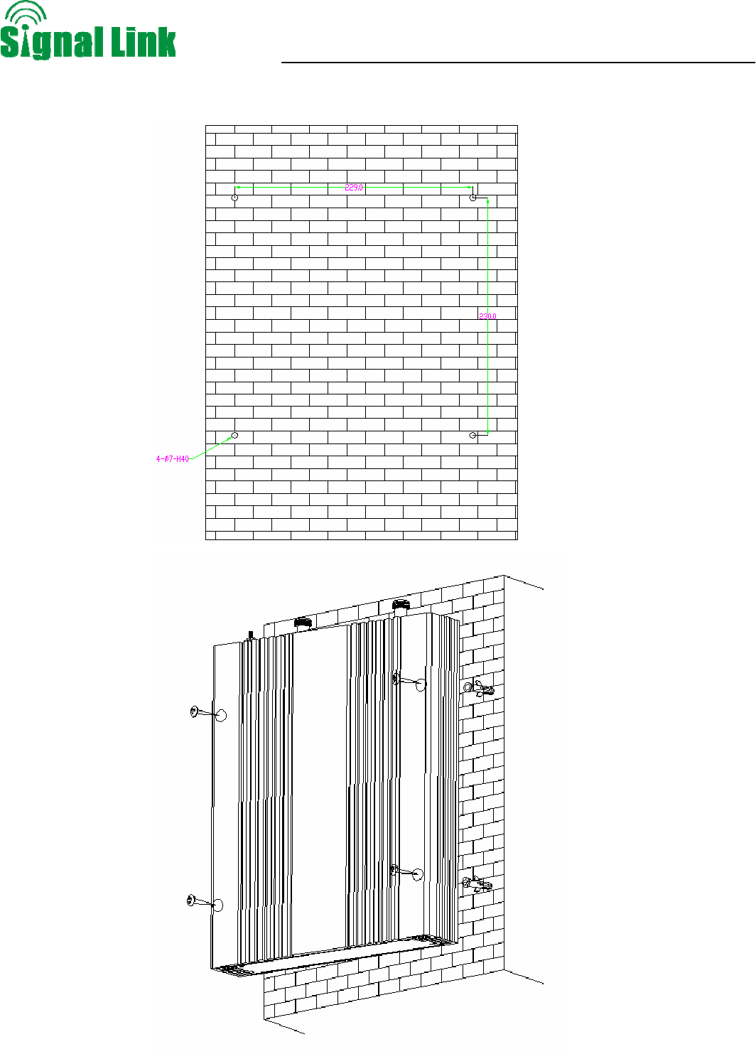
e) Add isolation net at the back of the antenna
8.8.6. Detecting Repeater
When you cannot find the reason why the receiving or transmitting channel is abnormal, you can use a
source-scanning spectrum analyzer to detect the repeater. (For the specifications, see the instructions for the
repeater.) Note that the amplitude of the introduced signal must agree with the actual condition.
----------------------------------------------------------------------------------------------------------------------------------------
Note:
When testing the downlink power of the repeater, use couplers or attenuators to avoid burning out the tester.
----------------------------------------------------------------------------------------------------------------------------------------
8.9. System Test
8.9.1. Check whether the coverage is good
1) Have a test with mobile phone or data card (engineering mobile phone is preferred). If the signals in most
areas have not been improved, please check below again:
The weak input signal leads to the low output power. Change the direction of donor antenna or Its
installation position or replace donor antenna with higher gain to increase input signal power level.
Check whether it is necessary to add more server antennas due to barriers, whether the repeater’s
power is enough; please install more server antennas or change with a repeater with higher power
level.
2) If the signals in small part of the areas have not been improved, please check below:
Check whether the service antenna is installed correctly or not, you may try to move the antnena
location improve coverage
Check if it is necessary to use use a directional antenna
Check whether it is necessary to add one or more antenna to enhance the coverage of special
areas.
Wireless Cellular Repeater User Manual
- 29 -
Remark:
Reduce the attenuation values*---at the same time must ensure the isolation
Increase the output power* ---recommended ways: adjust the donor antenna; increased
input signal strength.
8.9.2. Repeater can not communicate in Power-ON status
The power is on but there is signal fluctuation
1) The power is on but it has a signal fluctuation or a flash signal. The phone call can not achieved.
It shall be caused by the insufficient isolation between donor antenna and serve antenna,
Please take below measures:
¾ Firstly check whether the alarm LED becomes red. The red light shows the insufficient isolation.
¾ Secondly adjust the antenna directions or locations or enlarge the distance between them
¾ Thirdly reduce the repeater’s gain by ATT DIP if the above methods don’t work
The best minimum distance between donor antenna and serve antenna should be more than 10
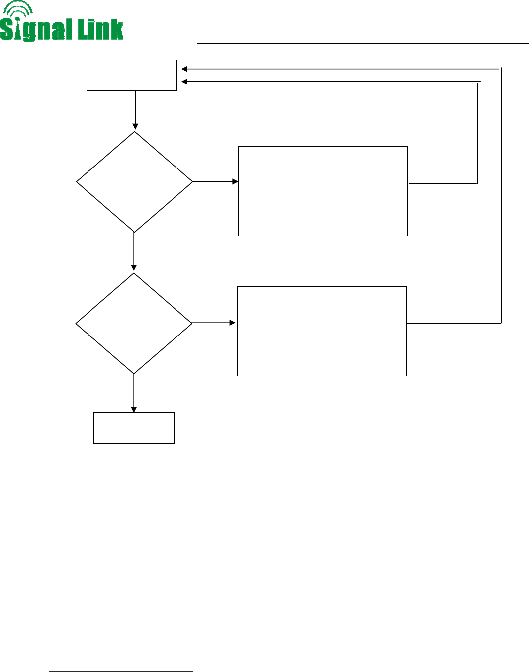
Test coverage
1) Mobility Service antenna
2) increase the number of service
antenna
3) reduce the attenuation values
4) increase the output power
Yes
No
Completion
Yes
No
1) Mobility Service antenna
2) increase the number of service
antenna
3) reduce the attenuation values
4) increase the output power
Check the signal
strength is fit
Check call quality
Wireless Cellular Repeater User Manual
- 30 -
meters.
The following measures can also be tried:
¾ Use the roof of the building to enlarge the isolation (Please try to place the donor antenna and
server antenna in different floors)
¾ Use some obstacles.(Such as wall )
2) The repeater’s power is on but the phone is not connected into the network and still can not
communicate.
¾ Reason 1: There are loose or wrong connections in the repeater system.
Solution: Please try to fasten the connections between the different parts of the system.
¾ Reason 2: The signals received by donor antenna of other operators nearby are too strong. (For
example, the other operators’ signals are 10 dB stronger than the needed signals.)
Solution 1: Change the direction of donor antenna or its installation position, so that the gap of
signal strength between operators are reduced.
Solution 2: Use barriers (like buildings) to block signals of other operators.