JDTECK JD60-9-19-LC Wireless Cellular Repeater User Manual
JDTECK INC Wireless Cellular Repeater Users Manual
JDTECK >
Users Manual
Meaning
Automatic Gain Control
Base Transmitting Station (Cell Tower)
Code Division Multiple Access
Decibel – (A unit of measure for signal strength)
Downlink (Communication channel from cell tower to mobile device)
Outdoor Antenna (Antenna that donates an input signal)
Global System for Mobile Communications
Integrated Digital Enhanced Network
Liquid Crystal Display
Light Emitting Diode
Long Term Evolution
Mobile Station
Personal Communication System
Radio Frequency
Uplink (Communication channel from mobile device to cell tower)
AGC
BTS
CDMA
dB
DL
Donor
GSM
iDEN
LCD
LED
LTE
MS
PCS
RF
UL
Abbreviations…………………………………………..………………………………..2
Safety……………………………………………………………………….……………….2
1. Preface………………………………………………………………………………... 3
2. Introduction / Features & Functions……………………………………..5
3. Installation…………………………………………………………………………….7
3.1 Installation Procedure………………………………………...………………8
3.1 Installation Procedure – Con’t……………………………………………9
3.2 Antenna Installing and Cable Wiring………………………..………10
3.3 Manual Gain Adjustment - UL / DL……………………..……………11
3.4 Testing……………………………………………………………………….……..15
3.5 Trouble Shooting………………………………………………..…………….16
Specifications……………………………………………………………………..…..17
FCC Statement………………………………………………………...……….……18
Repeater Settings….………………………………………………...…………..…19
Terminology
User Warnings – MUST READ!
1. This repeater must ONLY be used for the purpose it was
intended for. Making any alternations to the design layout
without first consulting with a trained technician can result in
interference to the operator’s network and liability by the end
user.
2. Please read this entire manual carefully before using this product!
3. Only the power supply that came with the repeater should be
used at all times. It is highly recommended that the repeater
is grounded and lightning protection used.
4. Do not attempt to open any part of the repeater. This will void
the warranty and can cause an electric shock. Electrostatic
can also cause damage to the internal components.
5. Please keep away from any heating-equipment, because the
repeater will dissipate heat when working. Do not cover the
repeater with anything that influences heat-dissipation.
6. Do not place or mount the repeater in a location that is exposed
to the elements. This will void the warranty and can cause an
electric shock.
1 2
1
N
r
a
m
c
p
w
t
h
t
e
F
w
m
g
n
T
c
e
i
t
c
a
e
a
s
T
s
r
e
a
A
a
a
b
c
c
p
n
T
c
a
c
a
t
o
3
1
. Preface
N
owadays, persona
l
a
te and persons ar
e
m
obile communicati
o
c
ommunication net
w
p
resent second-gen
e
w
idely used all over
h
ird-generation (3G
e
chnology is widely
F
or example, Code
D
w
hich greatly exten
d
m
odulation. As an a
d
g
ood multi-channel
a
n
arrowband interfer
e
T
he CDMA network
c
overage will gradu
a
e
ffect makes netwo
r
t
self determines tha
c
onstruction should
a
dding carriers and
r
e
xpanding network
c
a
n auxiliary means
o
hould to provide co
T
he cost of wireless
imple. They have t
h
e
peaters can help
a
a
t a minimum cost.
A
cellular tower typi
c
a
relatively small co
v
a
ccess it is limited a
b
est way of solving
t
c
overage to fully util
i
c
ellular network con
s
p
eripheral devices t
o
n
etwork itself.
T
he complete cover
a
c
ellular network, but
a
network operator
s
c
omplete coverage.
a
reas, office buildin
g
o
consummate the
n
l
mobile communic
a
e
having higher exp
o
n network. A high-
s
w
ork has become th
e
e
ration (2G) mobile
the world, but mos
t
) and forth-generat
i
used in Europe, N
o
D
ivision Multiple A
c
d
s the signal width -
d
vanced wireless c
o
a
ccess capability, a
e
nce capability and
has, what is called
a
lly shrink as the ce
r
k planning more co
t the load of the ne
t
be higher than that
r
oaming agreemen
t
c
apacity, and addin
g
o
f capacity expansi
o
ntinuous coverage,
repeaters are relat
i
h
e functions of a mi
a
BTS or Node B to
c
ally supports a lar
g
v
erage footprint. Th
nd a large amount
o
t
his problem is to u
s
i
ze the telecommu
n
s
truction in Asia, re
p
o
cover blind areas
a
ge is not only a pr
e
also a factor that a
s
hould first conside
r
The seamless cov
e
g
s, super markets,
a
n
etwork.
a
tion is developing
a
ectations and dem
a
s
peed and high-ca
p
e
trend of future de
v
communication sy
s
t
ly in developing na
t
on (4G) mobile co
m
o
rth America and K
o
c
cess (CDMA) tech
n
- the so-called spr
e
o
mmunication tech
n
nti-multipath fading
security protection
a “cell breathing ef
f
ll load increases. T
h
mplicated. The CD
M
t
work at the early s
t
of the GSM netwo
r
t
s between them is
g
BTS’s or Node B
b
o
n. The aim of the r
a
instead of hotspot
i
vely low and the c
o
ni BTS or Node B.
O
achieve the optim
a
g
e capacity of users
erefore, the numbe
o
f channel resourc
e
s
e repeaters to ext
e
n
ication resources.
F
p
eaters are no lon
g
in the network but
a
e
requisite for a hig
h
ttracts users. From
r
providing a radio
n
e
rage in urban area
s
a
nd top grade hotel
s
a
t a very rapid
a
nds on the
p
acity
v
elopment. At
s
tems like GSM is
t
ions, whereas
m
munication
o
rea.
n
ology is used
e
ad spectrum
n
ology, it features
capacity, anti-
capabilities.
f
ect”. That is, the
h
e cell breathing
M
A technology
t
age of
r
k. Therefore,
a major means of
b
ase stations is
a
dio network
coverage.
o
nstruction is
O
n the network,
a
l network quality
but is affected by
r of users who can
e
s are wasted. The
e
nd the BTS
F
or example, in
g
er considered as
a
s part of the core
h
quality mobile
this point of view,
n
etwork with a
s
, heavy traffic
s
is the first step
In such
repeat
e
antenn
a
or freq
u
Becau
s
popula
t
simply
u
buildin
g
are us
e
fiber s
o
Since t
h
the nu
m
may en
power
e
areas.
Repeat
and co
m
its high
indoor
s
rooms,
They a
r
very su
a background, JD
T
e
rs that are applica
b
a
system. (DAS) R
e
u
ency used today.
s
e a large amount o
f
t
ed urban areas, th
e
u
sed to cover small
g
s or sub-ground lo
c
e
d when optical fibe
r
o
lution is not cost ef
f
h
e number of repe
a
m
ber of buildings to
d up feeding from
o
e
d repeaters (below
ers adopt an integr
a
m
bines the RF mod
selectivity, stability
s
ignal distribution i
n
hotels, tea shops,
n
r
e also used to cov
e
itable to signal opti
m
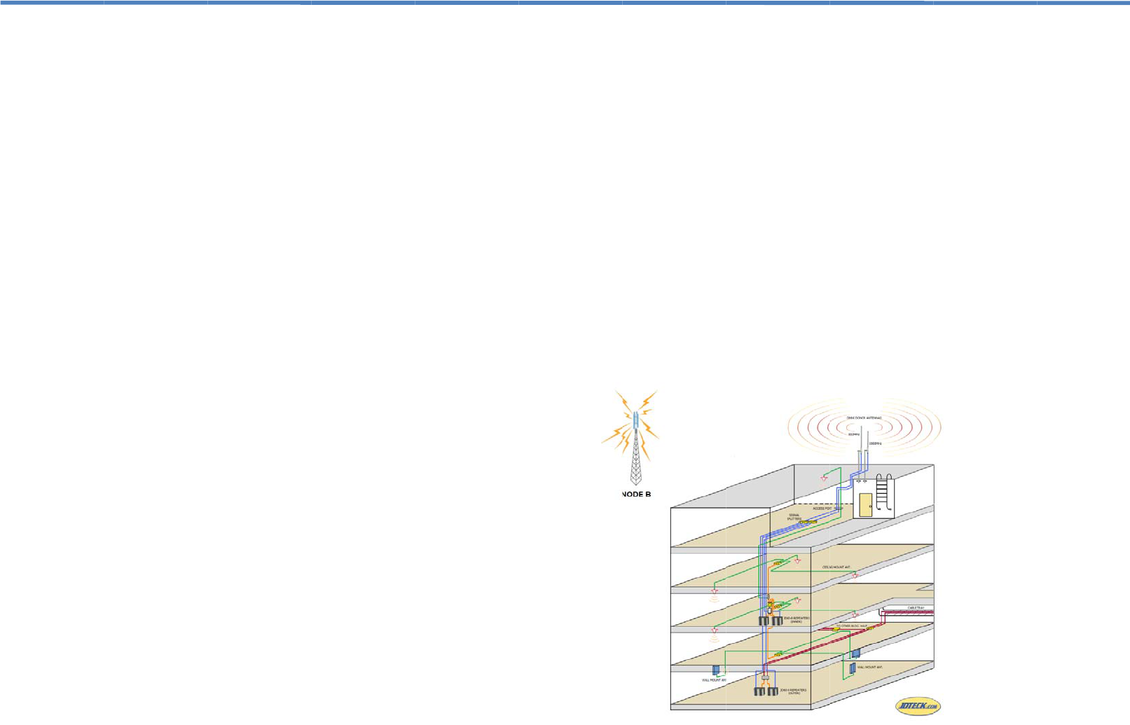
Figure 1 s
h
T
ECK has successf
u
b
le to any mobile n
e
e
peaters are availa
b
f
BTS or Node B d
e
e
re is usually no lar
g
blind areas and pr
o
c
ations. Typically, r
a
r
s are not available
f
ective.
a
ters on a cellular n
e
be covered in a sp
e
o
ne BTS or Node B
.
1 W) should be de
p
a
ted module conce
p
ule and the monito
r
and reliability, rep
e
n
small areas such
a
n
ight clubs, and caf
e
e
r shadow areas o
u
m
ization in densely
h
ows the applications
u
lly developed adv
a
e
twork and indoor d
i
b
le to support any t
e
e
vices are deploye
d
g
e blind area. Rep
e
o
vide signal covera
a
dio frequency (RF
)
in buildings or whe
e
twork usually incr
e
e
cific sector, multipl
.
In view of this, onl
y
p
loyed in densely p
o
p
t. It is compact in
s
r
ing mode in one u
n
e
aters are widely ap
a
s office buildings,
m
e
s where signals a
r
u
tdoors. Such repe
a
populated urban a
r
of the repeaters.
a
nced
i
stributed
e
chnology
d
in densely
e
aters are
ge inside
)
repeaters
n using a
e
ases with
e repeaters
y
low
o
pulated
s
tructure
n
it. Owing to
plied to
m
eeting
r
e shielded.
a
ters are
r
eas.
4
4
2
T
f
o
o
s
I
t
fi
a
T
s
e
(
D
r
e
e
i
n
T
r
e
c
r
e
t
h
r
e
f
u
t
h
m
d
J
a
c
t
h
a
T
t
o
A
G
A
R
O
5
2
. Introductio
n
T
his full duplex mob
o
r providing a wirel
e
o
ffice building, unde
hopping mall, outd
o
t
is designed to imp
ltering and re-trans
a
rea via a distribute
d
T
o maintain safe an
d
ignal oscillation de
t
e
nvironmental statu
s
D
ownlink Alarm &
U
e
d, (depending on
t
e
ither band, or if the
n
terference to the c
e
T
his repeater also h
a
e
duce the output p
o
c
an vary from 15-20
d
e
duction in gain ne
e
h
e AGC, then the e
n
e
peater called man
u
u
rther reduce the o
u
h
e front of the unit t
m
anually attenuate
(
d
ownlink individuall
y
DTECK’s repeater
s
a
utomatically shuts-
d
c
ellular network if n
o
h
e repeater’s LEDs
a
ll times for optimu
m
T
he main cause of
s
o
o close in proximit
y
A
larm LED status c
h
G
reen
- System fun
c
A
mber
- Mild detect
R
ed
- Strong signal
O
ff
– Repeater is n
o
n
ile communications
e
ss improvement in
r-ground parking lo
t
o
or park or any oth
e
rove the call qualit
y
mitting the signals
f
d
antenna system (
D
d
specific output si
g
t
ection circuits with
s
. The Alarm LEDs
U
plink Alarm) will c
h
t
he intensity) if the
s
input signal is bey
o
e
llular network, the
a
s an automatic ga
i
o
wer of the repeate
r
d
B depending on t
h
e
ded to take the un
i
n
d user can make
u
u
al gain control (M
G
u
tput gain of the re
p
o navigate through
(
reduce) the repeat
e
y
.
s
also feature a Net
w
d
own the transmis
s
o
adjustments are
m
. You will want to
m
m
system performa
n
s
ignal oscillation is
w
y
to the outdoor an
t
h
art and recommen
d
c
tioning well / no er
ion of signal oscilla
t
oscillation.
o
t transmitting (MU
T
repeater from JDT
the cellular recepti
o
t
, warehouse, apar
t
e
r large coverage a
r
y
of an area by rece
f
rom the base stati
o
D
AS) or distributed
g
nal levels, this rep
e
color changing LE
D
located on the fron
t
h
ange color from gr
e
s
ystem detects sign
o
nd a safe limit so
a
repeater will indica
t
i
n control (AGC) fe
a
r
if oscillation is det
e
h
e model of your re
p
i
t out of alarm exce
e
u
se of yet another f
e
G
C). This allows th
e
p
eater by using the
the liquid crystal di
s
e
r’s output gain of
e
w
ork Safe / MUTE
f
s
ion side of the rep
e
m
ade to eliminate al
a
m
ake sure the LEDs
n
ce.
w
hen any of the ind
o
t
enna on the roof.
d
ed action:
rors.
t
ion.
T
E Activated)
ECK is perfect
o
n inside a large
t
ment building,
r
ea requirement.
iving, amplifying,
o
n into a specified
antenna grid.
e
ater has built-in
D
s to indicate its
t
of the unit
e
en to amber or
al oscillation in
a
s to avoid
t
ed this.
a
ture which will
e
cted. This range
p
eater. If the
e
ds the range of
e
ature of this
e
end user to
push buttons on
s
play (LCD) and
e
ither the uplink or
f
eature that
e
ater to protect the
a
rm readings on
remain green at
o
or antennas are
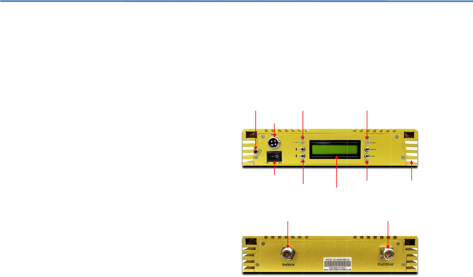
Feat
u
S
l
L
E
S
u
L
o
A
A
G
M
M
L
C
H
Grounding
P
u
res & Functi
o
l
eek attractive hou
s
E
D indicators to m
o
u
pports all technol
o
o
w power consump
t
LC function. (Auto
L
G
C function. (Auto
m
M
GC function. (Man
u
M
UTE function. (Sh
u
C
D Interface. (User
eat Sink cooling fin
s
Stud
P
ower Switch
DC Power Plug
UL A
l
Up / Dow
n
Outdoor Port
o
ns
s
ing.
o
nitor environmenta
l
o
gies including, GP
R
t
ion.
L
imit Control – will
n
m
atic Gain Control)
u
al Gain Control)
u
ts down if no chan
g
Friendly Digital Int
e
s
to dissipate heat
q
LCD Scree
n
l
arm
n
Button
l
status.
R
S, EDGE, CDMA
&
n
ot exceed max rat
e
g
e in environmental
e
rface)
q
uickly and efficien
t
n
Enter Button
DL Alarm
Indoor
&
UMTS.
e
d power)
conditions)
t
ly
Heat Sink Fins
6
Port
3. Installation
1. The repeater’s main function is to improve weak RF signals to an area.
2. Selecting the appropriate accessories that are compatible with the
frequency of the repeater is very important for optimal system
performance. An 850Mhz Repeater needs to be used with accessories
that supports the 850Mhz band. In the same way, choosing accessories in
the 1900Mhz Band needs to go with a 1900Mhz Repeater etc. For dual
band or multi-band repeaters, please ensure the peripheral components
used supports all the frequencies needed.
3. The signal strength from the outdoor antenna directly affects the efficiency
of the indoor coverage. It is very important to choose the location of the
outdoor antenna carefully. With this in mind, it is not recommended that
the donor antenna be installed in an attic or at the side of a building.
4. The repeater is a two-way (full duplex) signal amplifier. Therefore there
needs to be proper isolation between the outdoor antenna and indoor
antenna in order to avoid signal oscillation on the repeater. (Interference)
There needs to be more than 15dB of isolation above the repeater gain.
For example, if the repeater gain is 60dB, then you need 75dB of isolation
between outdoor antenna and indoor antenna.
5. The repeater gain is adjustable for both the uplink / downlink individually.
Depending on the environment, the end-user may need to adjust the
repeater gain to achieve optimum performance and desired coverage.
6. The repeater is designed to amplify the input signal, filter it and retransmit
it to the desired area via service antennas. In order to reach the best
performance, the outdoor signal should be greater than -80dBm, and not
over +10dBm. If the outdoor signal is very weak, then a pre-amplifier may
be used.
7. Calculating the Link budget before setting the repeater gain.
Link budget calculation:
Outdoor signal strength – Loss of accessories (cable, connectors,
splitters, Directional Couplers) + Antenna gain (outdoor antenna, indoor
antenna) + Repeater gain = Indoor signal strength.
8. For all cellular applications, you need to use 50 Ohm rated coax.
Besides affecting voice quality, using any other impedance of coax will
put an extra load on your repeater and shorten its life span.
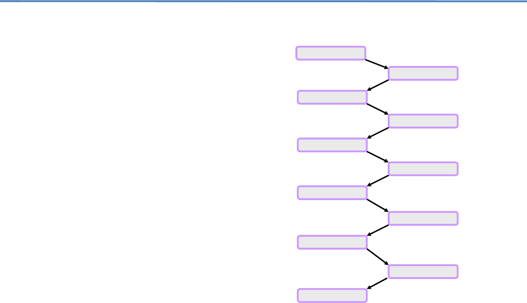
3.1 Installation Procedure
Site Surve
y
Installation Plannin
g
Link Bud
g
et Calculatin
g
Install Outdoor Antenna
Cable Installation
Install Re
p
eater
Install Indoor Antennas
Si
g
nal Measurement
Gain Ad
j
ustment
Test for Call Qualit
y
Trouble Shootin
g
7 8
3
W
m
r
e
9
3
.1 Installation
P
Check the cont
e
Identify a suita
b
antenna on you
antennas or im
m
input signal fro
m
Ensure the loca
and at the sam
e
complete your i
n
Install the dono
r
the indoor base
including any s
e
Connect the in
d
the unit and mo
If the donor ant
e
nearest cell to
w
commissioning,
best signal stre
n
while making s
u
W
e suggest getting
s
m
onitor both your m
e
peater at the sam
e
If signal oscillat
i
relevant band
w
LEDs turn gree
n
If the signal os
c
relevant band
w
as a result of
service antenn
a
and then matc
h
settings for adj
u
P
rocedure – C
o
e
nts supplied.
b
le location where y
o
r roof or at an elev
a
m
ediate obstruction
s
m
the cell tower or t
o
tion is properly isol
a
e
time, ensure the
c
n
stallation.
r
antenna and rout
e
unit.
DO NOT COI
e
rvice loops.
d
oor service antenn
a
nitor the LED statu
s
e
nna used is not a
n
w
er location is not k
n
then you may nee
d
n
gth or call quality i
s
u
re the LEDs sta
y
g
s
omeone to help r
o
obile device (Phon
e
e
time.
i
on is between 1~4
d
w
ill turn amber. Plea
n
. (See attenuation
c
illation is between
w
ill turn red, and th
e
not having enou
g
a
s. In this case at
t
h
the UL gain to th
u
stments)
o
nt.
o
u would like to mo
a
ted location, free o
f
s
. Confirm this loca
o
wers you would li
k
a
ted from the indoo
c
able length supplie
d
e
the coax to the pr
o
L UP
any excess
c
a
s, coax and powe
r
s
for errors.
n
omni-directional a
n
n
own at the time of
s
d
to rotate the dono
s
achieved on your
reen on the repeat
e
o
tate the donor ante
e
or PC Card) and
th
d
B then the Alarm
L
se adjust the DL re
adjustment)
10-15dB then the
A
e
repeater will then
g
h isolation betwe
e
t
enuate the DL gai
e same gain value
unt the donor
f
any other
tion has the best
k
e to support.
r antenna
d
is sufficient to
o
posed location for
c
oax you may have,
r
supply. Power up
n
tenna or the
s
ystem
r antenna until the
mobile device,
e
r.
n
na while you
h
e LEDs on the
L
ED for the
peater gain till the
A
larm LED for the
shut down. This is
e
n the donor and
n on the repeater
. (See attenuation
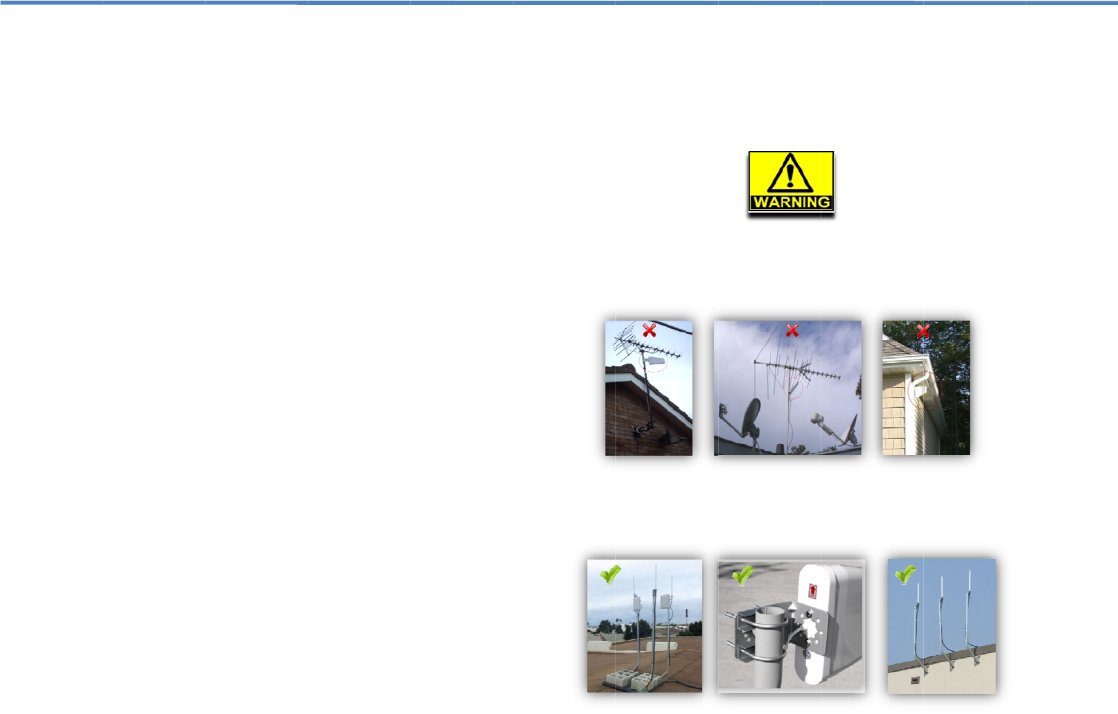
3.2 A
n
We do
n
in the a
quality
o
signal
o
your re
p
D
P
D
It i
s
fre
e
br
a
n
tenna Installa
t
n
ot recommend ins
t
ttic or at the side o
f
o
f the input signal f
r
o
scillation taking pl
a
p
eater.
D
o not install the d
o
P
lease take the ne
c
D
o not mount near
o
s
recommended th
a
e
of any immediate
a
cket is recommen
d
t
ion and Coax
C
t
alling the donor an
f
a single story buil
d
r
om the cell tower.
A
a
ce, thus having to
a
o
nor antenna near
h
c
essary safety mea
s
o
r in the path of oth
a
t you mount your d
obstructions. Maki
n
d
ed for optimum an
t
C
able Wiring
tenna of your repe
a
d
ing. Doing so will r
e
A
lso you increase t
h
a
ttenuate the outpu
t
h
igh voltage power l
s
ures when workin
g
er antennas or sat
e
onor antenna in a
s
n
g use of a pole or
m
t
enna performance.
a
ter system
e
duce the
h
e risk of
t
power of
ines.
g
on heights.
e
llite dishes.
s
pot that is
m
ounting
1
10
3
I
n
n
a
/
W
U
Do
w
U
D
o
11
3
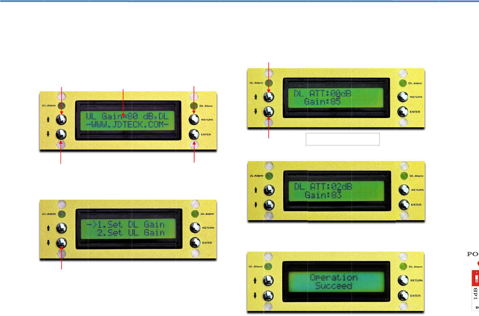
.3 Manual Gai
n
n
order to meet a
n
n
etwork integration,
a
llows you to manu
a
DL attenuator cont
r
W
hen your repeate
r
U
L and DL gain valu
Click the
ENTER
b
Click the
UP
or
D
O
would
w
n Navigation Button
p Navigation Button
o
wn Navigation Butto
n
n
Adjustment
~
n
d maintain safe e
n
this repeater is
e
a
lly control the Upli
n
r
ol range is from 0d
r
is switched on, th
e
es and output pow
e
utton to access the
O
WN
navigation bu
t
like to attenuate. (
U
A
ctive Power St
a
n
~
UL / DL
n
vironmental condi
t
e
quipped with an
L
n
k / Downlink gain i
n
B to -31dB by 1dB
i
e
LCD screen will
d
e
r setting in a scroll
menu to add or re
m
t
ton to access the
d
U
PLINK or DOWNL
E
a
tus Scrolling
t
ions for seamless
L
CD interface that
n
dividually. The UL
i
ncrements.
d
isplay the current
ing sequence.
m
ove attenuation.
d
esired band you
INK)
nter / Select Button
Return Button
3.3 M
a
Click th
would l
i
attenu
a
DOWN
T
Ple
a
ENT
E
Down N
Up Navi
a
nual Gain Adj
u
e ENTER button a
g
i
ke to attenuate. Th
a
tion value. (Default
navigation buttons
T
he following exam
p
a
se note: For the s
e
E
R button after, or i
t
response
avigation Button
gation Button
u
stment ~ UL /
g
ain after you have
is will then bring yo
is 0dB) You can t
h
to add the desired
p
le shows a value
o
e
lected value to tak
e
t
will not register. Y
o
when the change
w
The default of UL
/
attenuator is at 0dB.
DL – Con’t.
selected the desire
d
ur prompt to the cu
r
h
en use either the
U
amount of attenuat
i
o
f 2dB has been sel
e
e
effect, you must
p
o
u will then get a c
o
w
as successful.
/
DL gain
(Full Power)
d
band you
r
rent
U
P or
i
on.
e
cted.
p
ress the
o
nfirmation
12
2
3
A
g
t
h
I
n
t
h
w
a
M
W
o
f
a
O
O
A
a
s
u
r
e
p
I
f
a
c
p
D
o
13
3
.3 Manual Gai
n
A
fter the change h
a
g
reen or if further at
t
h
en be sure to mat
c
n
some deploymen
t
h
e location of the r
e
w
ould be best not t
o
a
ffect the optimu
m
M
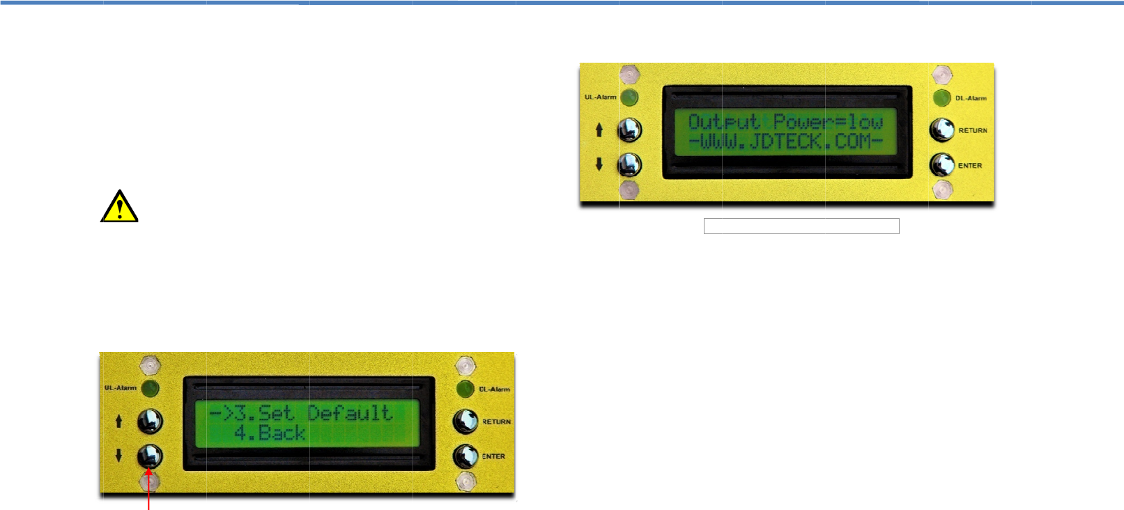
ain Menu
W
hen in the main
m
o
ptions 3 & 4. Whe
n
a
ctory default. (No
A
O
ption 4 simply allo
w
Click
t
O
utput Power
A
nother neat featu
r
a
ddition to the cur
r
creen, it also displ
a
u
sed as an indica
t
e
ceived by the rep
e
p
ower will display “
O
f
your donor anten
n
a
nd the Output Po
w
c
ompromised conn
e
p
re-amp to the syst
e
A
void putting
o
wn Navigation Butto
n
Adjustment ~
a
s been made, mo
t
enuation is neede
d
c
h the UL gain to th
e
t
s, the end user ma
e
peater is very far
f
o
exceed a 5dB di
f
m
performance of
m
enu, if you contin
u
n
selected, option
3
A
ttenuation = Full
P
w
s you to exit the
m
t
he ENTER button t
r
e about the LCD
r
ent UL and DL g
a
a
ys the active outp
u
t
or to determine h
e
ater. For example
O
utput Power = Lo
w
n
a is in the best loc
a
w
er is still Low, th
e
e
ctor on your input
c
e
m to boost the we
a
more than a 5dB diff
e
n
UL / DL – Con
’
nitor the DL alarm
d
. If the DL LED re
m
e
same dB value.
y decide to have a
f
rom the cell tower.
f
ference on the DL
the repeater’s b
a
u
e to scroll down th
3
will allow you res
e
ower).
m
ain menu back to t
h
o access any selec
Interface on this
r
a
in values that sc
r
u
t power level of th
e
ow strong an inp
u
if the input signal i
s
w
”.
a
tion for receiving
a
e
n it could be that
c
oax cable, or that
a
k input signal.
e
rence between the U
p
’
t.
LED to see if it’s
m
ains a solid green,
stronger UL gain if
In this instance, it
gain as this could
a
ndwidth capacity.
e LCD will display
e
t the dB values to
h
e home screen.
tion.
r
epeater is that in
r
olls on the home
e
unit. This can be
u
t signal is being
s
weak, the output
a
good input signal
you either have a
you need to add a
p
link and Downlink.
3.3 M
a
When
This re
p
If the in
either,
a
occur i
f
(RSSI)
oscillati
from th
e
antenn
a
To det
e
discon
n
repeat
e
the cell
DL gai
n
match
t
indoor
a
If after
r
back to
of your
should
When
c
covera
g
showin
g
be that
howev
e
the upli
We en
c
make s
always
a
nual Gain Adj
u
do
y
ou ad
j
ust t
h
p
eater is equipped
w
put gain is too high
a
mber or red indica
t
f
the donor antenna
from the cell tower
on is taking place.
S
e
indoor service an
t
a
outside.
e
rmine what is the c
a
n
ect the indoor ant
e
e
r. If the LED does
n
tower is very stron
g
n
by 1dB increment
s
t
he same attenuati
o
a
ntenna / service li
n
r
econnecting the in
d
amber or red then
indoor and outdo
o
therefore have mor
c
omplete, try maki
n
g
e while monitorin
g
g
strong signal str
e
you need to atte
n
e
r that you do not
w
nk and downlink va
c
ourage you to call
u
ure you have seam
happy to help. 1-8
6
R
e
u
stment ~ UL /
h
e Repeater Gai
n
w
ith an alarm featu
r
, the Alarm LED wil
t
ing the intensity or
is in a location wh
e
is extremely good (
S
ignal Oscillation i
s
t
enna is being rece
i
a
use of your Alarm
e
nna / service line fr
n
ot change to gree
n
g
and it is highly re
c
s
till the LEDs turns
o
n value to the UL,
a
n
e again.
d
oor antenna or se
r
signal oscillation is
o
r antennas being t
e separation.
n
g some test calls
g
the LEDs to see
e
ngth but your calls
n
uate your uplink
g
w
ant to have more
lues for optimum s
y
u
s when commissi
o
less integration to t
6
6-4-JDTECK (53-
8
e
peater not receiving a g
o
DL – Con’t.
n
?
r
e that monitors th
e
l change color from
the error. High inp
u
e
re the receive sign
a
-50dB or better) or
s
when the amplifie
d
i
ved back into the d
LED changing colo
om the “INDOOR”
p
n
, then your input si
g
c
ommended you at
t
green again. Then
a
fter which you can
r
vice line, the LED
c
taking place. This i
s
oo close to each ot
h
throughout the de
s
if it changes colo
r
are not going thro
u
g
ain a bit more. K
e
than a 5dB differe
n
y
stem performance
.
o
ning your repeater
he cellular network
.
8
325).
o
od input signal.
e
input gain.
green to
u
t gain can
a
l strength
if signal
d
signal
onor
r you can
p
ort of the
g
nal from
t
enuate the
you must
connect the
c
hanges
s
the result
h
er and
s
ired area of
r
. If you are
u
gh, it could
e
ep in mind
n
ce between
.
system to
.
We are
14
4
3
15
3
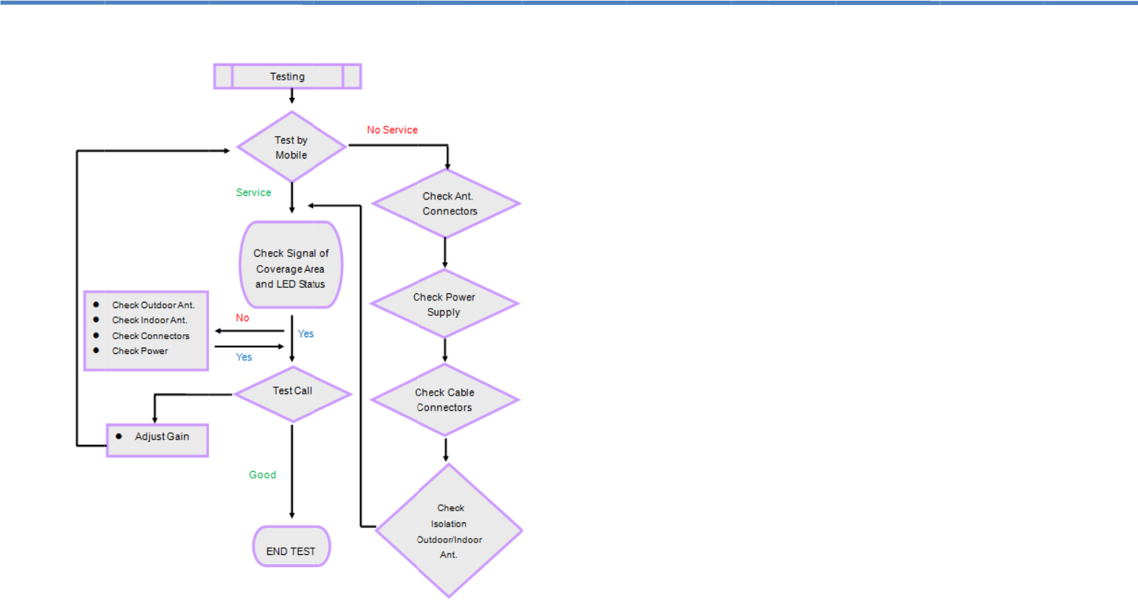
.4 Testing
3.5 Tr
Q1. W
h
A
nswe
1. Che
c
2. Che
c
3. Che
c
4. Che
c
5. Che
c
6. Che
c
7. Che
c
Q2. W
h
A
nswe
1. Che
c
2. Che
c
3. Che
c
4. Cha
n
5. Che
c
6. Depl
o
Q3. W
h
de
t
A
nswe
1. Che
c
2. Cha
n
3. Red
u
Q4. Th
e
A
nswe
1. Che
c
2. Che
c
3. Che
c
4. Con
f
Q5. W
h
A
nswe
1. Che
c
2. MU
T
oubleshooting
h
y is there still no
s
r:
c
k the power on re
p
c
k the connector of
c
k the connectors o
f
c
k the outdoor sign
a
c
k to make sure the
c
k the connector of
c
k the cable type is
h
y the signal stren
r:
c
k the outdoor sign
a
c
k repeater is full g
a
c
k all of the connec
t
n
ge the location of
o
c
k the cable type is
o
y more indoor ant
e
h
y can’t I make a c
t
ect a signal?
r:
c
k LED status of re
p
n
ge the location of
o
u
ce the UL gain of t
h
e
signal is not sta
b
r:
c
k to see if the outd
o
c
k the location of th
e
c
k the RF cable is b
f
irm direction of don
h
y is the LED on t
h
r:
c
k the power sourc
e
T
E feature is active.
s
ignal after install
p
eater and power s
u
outdoor antenna is
f
RF cable are tight
a
l is strong enough
antenna is installe
d
indoor antenna is ti
suitable or not.
gth is too weak o
n
a
l and antenna dire
c
a
in or not.
t
ors are tight.
o
utdoor/indoor ante
n
suitable or not.
e
nnas.
all after installatio
p
eater to make sur
e
o
utdoor / indoor ant
e
h
e repeater.
b
le after turning o
n
o
or signal is stable
e
donor antenna. T
o
roken or not and h
a
or antenna in relati
o
h
e front of the rep
e
e
is normal or not.
Attenuate gain of r
e
ing the equipmen
t
u
ppl
y
.
tight or not.
or not.
or not.
d
correctly.
ght or not.
n
the edge of area
?
c
tion.
n
na.
n, even though I
c
e
alarms are green.
e
nna.
n
the repeater po
w
or not.
o
o close to other a
n
a
s no coils.
o
n to cell tower.
e
ater not lit?
e
peater and cycle p
t
?
?
c
an
w
er.
n
tennas.
ower.
16
6
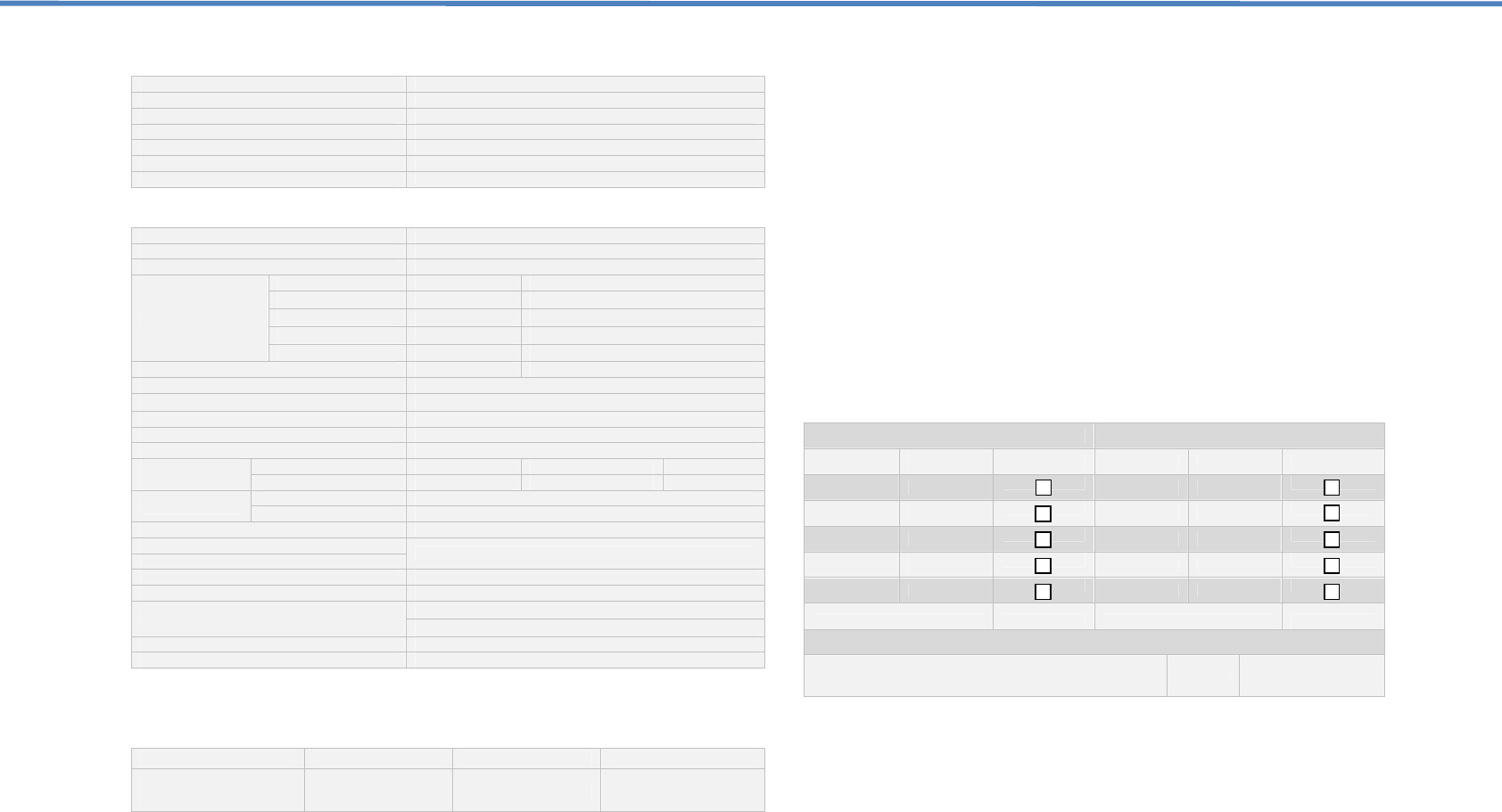
Mechanical Specifications
Input / Output Port N-Female
Impedance 50 Ω
Dimensions (W x D x H) 250 x 330 x 53mm
Weight ≤4.9Kg (10.8 Lbs)
Operating Temperature -10°C ~ 50°C
Environment Conditions IP40
Switching Adapter Input AC 100~240V, Output DC 12V / 6A
Record your repeater settings here.
Downlink Uplink
Dip Switch Value ON Dip Switch Value ON
1 1dB 1 1dB
2 2dB 2 2dB
3 4dB 3 4dB
4 8dB 4 8dB
5 16dB 5 16dB
Total dB Attenuated …………... Total dB Attenuated …………...
Adjusted By: ___________________________________ Date: ……./……/…………
FCC Statement
Changes or modifications not expressly approved by the party responsible
for compliance could void the user's authority to operate the equipment.
PLEASE NOTE: It is normal for your repeater to be quite warm while in use.
FCC Radiation Exposure Statement:
This equipment complies with FCC radiation exposure limits set forth for an
uncontrolled environment . This equipment should be installed and operated
with minimum distance 20cm between the radiator& your body.
This transmitter must not be co-located or operating in conjunction with any
other antenna or transmitter.
Frequency Specifications
Model JD60-9-19-LC
FCC ID SQX-JD60-9-19-LC
Filter Bandwidth GSM & EDGE& CDMA& WCDMA | PCS 60MHz
Output power
Uplink Downlink
GSM 20±1 dBm 30±1 dBm
EDGE 20±1 dBm 30±1 dBm
CDMA 20±1 dBm 30±1 dBm
WCDMA 20±1 dBm 30±1 dBm
Max. Gain 80dB 85dB
Gain Flatness CDMA & GSM: ≤8dB, PCS: ≤10dB
AGC Range ≧15dB ,auto shut off after 15dB
Maximum Input Power 0dBm
Gain Control Range(MGC) ≥31dB in step of 1dB by LCD menu
V.S.W.R ≤2
Spurious
Emission
9KHz~1GHz ≤-36dBm ≤-36dBm ≤-36dBm
1GHz~12.75GHz ≤-30dBm ≤-30dBm ≤-30dBm
CDMA System Rho p >0.980
ACPR Meets IS95 & CDMA2000
Modulation Accuracy ≥12.5%
Spurious Emission Mask Meet 3GPP TS 25.143 (V 6.2.0)
Input Inter-modulation
Peak Code Domain Error ≥-35dB @ Spreading Factor 256
Frequency Stability ≤0.01ppm
ACRR ≥30dBc / 30KHz @±5MHz
≥50dBc / 30KHz @±10MHz
Noise Figure (@ max gain) ≤6dB
Group Delay ≤4.5 micro Sec
Model Specifications
Classification Bandwidth Range
Frequency Range
PCS
DL -1930-1990 (MHz)
UL -1850-1910 (MHz)
17

NOTES
_________________________________________________________________________________
_________________________________________________________________________________
_________________________________________________________________________________
_________________________________________________________________________________
_________________________________________________________________________________
_________________________________________________________________________________
_________________________________________________________________________________
_________________________________________________________________________________
_________________________________________________________________________________
_________________________________________________________________________________
_________________________________________________________________________________
_________________________________________________________________________________
_________________________________________________________________________________
_________________________________________________________________________________
_________________________________________________________________________________
_________________________________________________________________________________
_________________________________________________________________________________
_________________________________________________________________________________
_________________________________________________________________________________
_________________________________________________________________________________
_________________________________________________________________________________
_________________________________________________________________________________
_________________________________________________________________________________
_________________________________________________________________________________
18