JDTECK JD60-9-AWS-LC Wireless Cellular Repeater User Manual
JDTECK INC Wireless Cellular Repeater Users Manual
JDTECK >
Users Manual
Meaning
Automatic Gain Control
Base Transmitting Station (Cell Tower)
Code Division Multiple Access
Decibel – (A unit of measure for signal strength)
Downlink (Communication channel from cell tower to mobile device)
Outdoor Antenna (Antenna that donates an input signal)
Global System for Mobile Communications
Integrated Digital Enhanced Network
Liquid Crystal Display
Light Emitting Diode
Long Term Evolution
Mobile Station
Personal Communication System
Radio Frequency
Uplink (Comm unication channel from mobile device to cell tower)
AGC
BTS
CDMA
dB
DL
Donor
GSM
iDEN
LCD
LED
LTE
MS
PCS
RF
UL
Abbreviations…………………………………………..………………………………..2
Safety……………………………………………………………………….……………….2
1. Preface………………………………………………………………………………... 3
2. Introduction / Features & Functions……………………………………..5
3. Installation…………………………………………………………………………….7
3.1 Installation Procedure………………………………………...………………8
3.1 Installation Procedure – Con’t……………………………………………9
3.2 Antenna Installing and Cable Wiring………………………..………10
3.3 Manual Gain Adjustment - UL / DL……………………..……………11
3.4 Testing……………………………………………………………………….……..15
3.5 Trouble Shooting………………………………………………..…………….16
Specifications……………………………………………………………………..…..17
FCC Statement………………………………………………………...……….……18
Repeater Settings….………………………………………………...…………..…19
Terminology
User Warnings – MUST READ!
1. This repeater must ONLY be used for the purpose it was
intended for. Making any alternations to the design layout
without first consulting with a trained technician can result in
interference to the operator’s network and liability by the end
user.
2. Please read this entire manual carefully before using this product!
3. Only the power supply that came with the repeater should be
used at all times. It is highly recommended that the repeater
is grounded and lightning protection used.
4. Do not attempt to open any part of the repeater. This will void
the warranty and can cause an electric shock. Electrostatic
can also cause damage to the internal components.
5. Please keep away from any heating-equipment, because the
repeater will dissipate heat when working. Do not cover the
repeater with anything that influences heat-dissipation.
6. Do not place or mount the repeater in a location that is exposed
to the elements. This will void the warranty and can cause an
electric shock.
1 2
1. Preface
Nowadays, personal mobile communication is developing at a very rapid
rate and persons are having higher expectations and demands on the
mobile communication network. A high-speed and high-capacity
communication network has become the trend of future development. At
present second-generation (2G) mobile communication systems like GSM is
widely used all over the world, but mostly in developing nations, whereas
third-generation (3G) and forth-generation(4G) mobile communication
technology is widely used in Europe, North America and Korea.
For example, Code Division Multiple Access (CDMA) technology is used
which greatly extends the signal width -- the so-called spread spectrum
modulation. As an advanced wireless communication technology, it features
good multi-channel access capability, anti-multipath fading capacity, anti-
narrowband interference capability and security protection capabilities.
The CDMA network has, what is called a “cell breathing effect”. That is, the
coverage will gradually shrink as the cell load increases. The cell breathing
effect makes network planning more complicated. The CDMA technology
itself determines that the load of the network at the early stage of
construction should be higher than that of the GSM network. Therefore,
adding carriers and roaming agreements between them is a major means of
expanding network capacity, and adding BTS’s or Node B base stations is
an auxiliary means of capacity expansion. The aim of the radio network
should to provide continuous coverage, instead of hotspot coverage.
The cost of wireless repeaters are relatively low and the construction is
simple. They have the functions of a mini BTS or Node B. On the network,
repeaters can help a BTS or Node B to achieve the optimal network quality
at a minimum cost.
A cellular tower typically supports a large capacity of users but is affected by
a relatively small coverage footprint. Therefore, the number of users who can
access it is limited and a large amount of channel resources are wasted. The
best way of solving this problem is to use repeaters to extend the BTS
coverage to fully utilize the telecommunication resources. For example, in
cellular network construction in Asia, repeaters are no longer considered as
peripheral devices to cover blind areas in the network but as part of the core
network itself.
The complete coverage is not only a prerequisite for a high quality mobile
cellular network, but also a factor that attracts users. From this point of view,
a network operator should first consider providing a radio network with a
complete coverage. The seamless coverage in urban areas, heavy traffic
areas, office buildings, super markets, and top grade hotels is the first step
to consummate the network.
In such a background, JDTECK has successfully developed advanced
repeaters that are applicable to any mobile network and indoor distributed
antenna system. (DAS) Repeaters are available to support any technology
or frequency used today.
Because a large amount of BTS or Node B devices are deployed in densely
populated urban areas, there is usually no large blind area. Repeaters are
simply used to cover small blind areas and provide signal coverage inside
buildings or sub-ground locations. Typically, radio frequency (RF) repeaters
are used when optical fibers are not available in buildings or when using a
fiber solution is not cost effective.
Since the number of repeaters on a cellular network usually increases with
the number of buildings to be covered in a specific sector, multiple repeaters
may end up feeding from one BTS or Node B. In view of this, only low
powered repeaters (below 1 W) should be deployed in densely populated
areas.
Repeaters adopt an integrated module concept. It is compact in structure
and combines the RF module and the monitoring mode in one unit. Owing to
its high selectivity, stability and reliability, repeaters are widely applied to
indoor signal distribution in small areas such as office buildings, meeting
rooms, hotels, tea shops, night clubs, and cafes where signals are shielded.
They are also used to cover shadow areas outdoors. Such repeaters are
very suitable to signal optimization in densely populated urban areas.
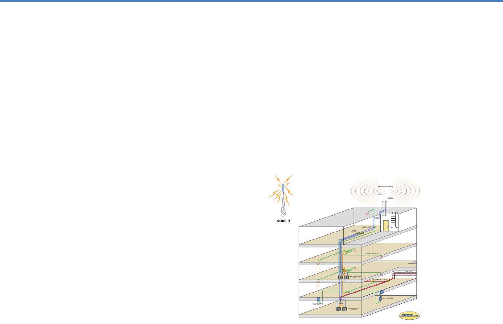
Figure 1 shows the applications of the repeaters.
3 4
2. Introduction
This full duplex mobile communications repeater from JDTECK is perfect
for providing a wireless improvement in the cellular reception inside a large
office building, under-ground parking lot, warehouse, apartment building,
shopping mall, outdoor park or any other large coverage area requirement.
It is designed to improve the call quality of an area by receiving, amplifying,
filtering and re-transmitting the signals from the base station into a specified
area via a distributed antenna system (DAS) or distributed antenna grid.
To maintain safe and specific output signal levels, this repeater has built-in
signal oscillation detection circuits with color changing LEDs to indicate its
environmental status. The Alarm LEDs located on the front of the unit
(Downlink Alarm & Uplink Alarm) will change color from green to amber or
red, (depending on the intensity) if the system detects signal oscillation in
either band, or if the input signal is beyond a safe limit so as to avoid
interference to the cellular network, the repeater will indicated this.
This repeater also has an automatic gain control (AGC) feature which will
reduce the output power of the repeater if oscillation is detected. This range
can vary from 15-20dB depending on the model of your repeater. If the
reduction in gain needed to take the unit out of alarm exceeds the range of
the AGC, then the end user can make use of yet another feature of this
repeater called manual gain control (MGC). This allows the end user to
further reduce the output gain of the repeater by using the push buttons on
the front of the unit to navigate through the liquid crystal display (LCD) and
manually attenuate (reduce) the repeater’s output gain of either the uplink or
downlink individually.
JDTECK’s repeaters also feature a Network Safe / MUTE feature that
automatically shuts-down the transmission side of the repeater to protect the
cellular network if no adjustments are made to eliminate alarm readings on
the repeater’s LEDs. You will want to make sure the LEDs remain green at
all times for optimum system performance.
The main cause of signal oscillation is when any of the indoor antennas are
too close in proximity to the outdoor antenna on the roof.
Alarm LED status chart and recommended action:
Green - System functioning well / no errors.
Amber - Mild detection of signal oscillation.
Red - Strong signal oscillation.
Off – Repeater is not transmitting (MUTE Activated)
Features & Functions
Sleek attractive housing.
LED indicators to monitor environmental status.
Supports all technologies including, GPRS, EDGE, HSDPA & UMTS.
Low power consumption.
ALC function. (Auto Limit Control – will not exceed max rated power)
AGC function. (Automatic Gain Control)
MGC function. (Manual Gain Control)
MUTE function. (Shuts down if no change in environmental conditions)
LCD Interface. (User Friendly Digital Interface)
Heat Sink cooling fins to dissipate heat quickly and efficiently
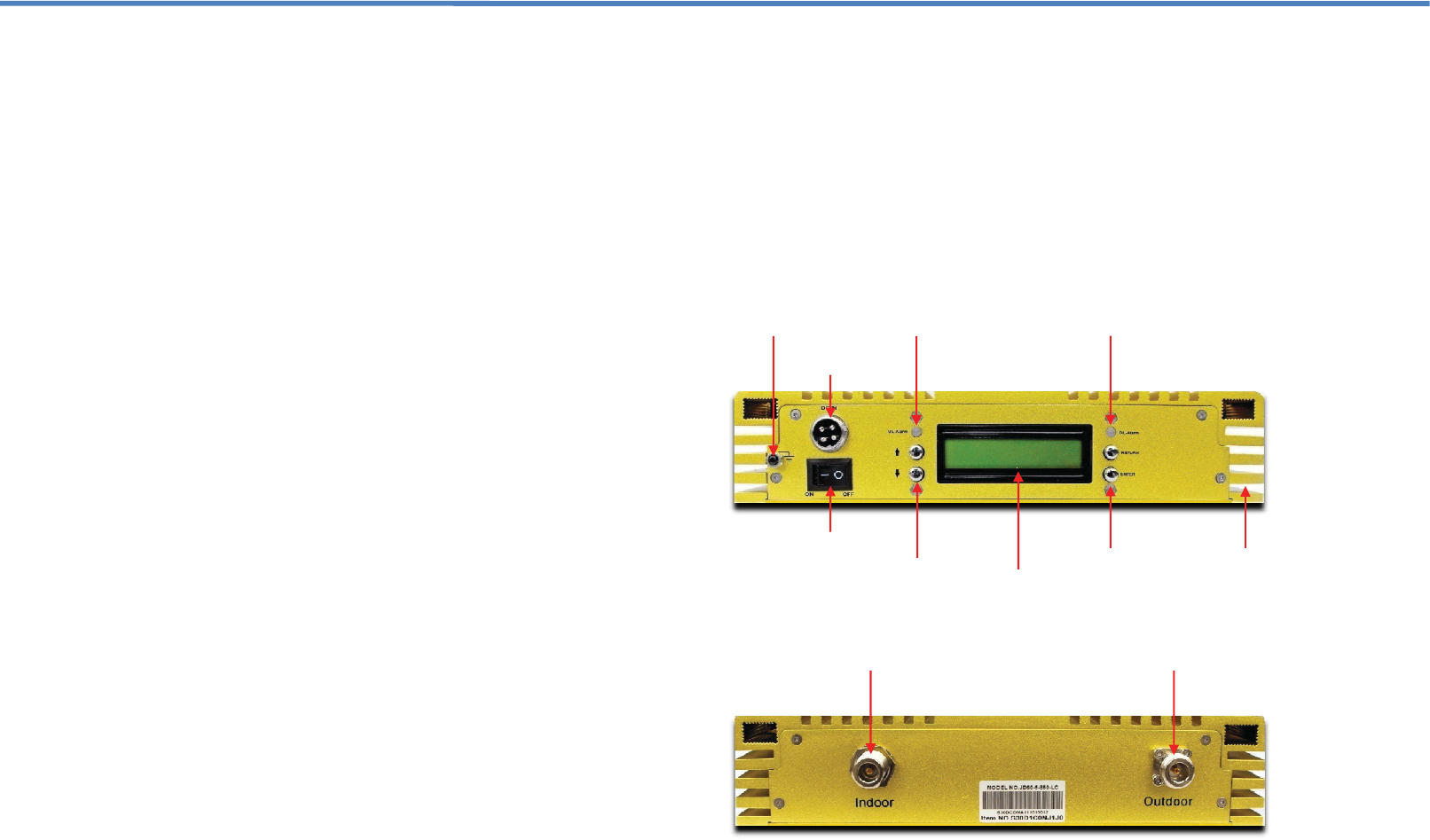
Grounding Stud
Power Switch
LCD Screen
DC Power Plug
UL Alarm
Enter Button
Up / Down Button Heat Sink Fins
DL Alarm
5 6
Outdoor Port Indoor Port
3. Installation
1. The repeater’s main function is to improve weak RF signals to an area.
2. Selecting the appropriate accessories that are compatible with the
frequency of the repeater is very important for optimal system
performance. An 850Mhz Repeater needs to be used with accessories
that supports the 850Mhz band. In the same way, choosing accessories in
the 1900Mhz Band needs to go with a 1900Mhz Repeater etc. For dual
band or multi-band repeaters, please ensure the peripheral components
used supports all the frequencies needed.
3. The signal strength from the outdoor antenna directly affects the efficiency
of the indoor coverage. It is very important to choose the location of the
outdoor antenna carefully. With this in mind, it is not recommended that
the donor antenna be installed in an attic or at the side of a building.
4. The repeater is a two-way (full duplex) signal amplifier. Therefore there
needs to be proper isolation between the outdoor antenna and indoor
antenna in order to avoid signal oscillation on the repeater. (Interference)
There needs to be more than 15dB of isolation above the repeater gain.
For example, if the repeater gain is 60dB, then you need 75dB of isolation
between outdoor antenna and indoor antenna.
5. The repeater gain is adjustable for both the uplink / downlink individually.
Depending on the environment, the end-user may need to adjust the
repeater gain to achieve optimum performance and desired coverage.
6. The repeater is designed to amplify the input signal, filter it and retransmit
it to the desired area via service antennas. In order to reach the best
performance, the outdoor signal should be greater than -80dBm, and not
over +10dBm. If the outdoor signal is very weak, then a pre-amplifier may
be used.
7. Calculating the Link budget before setting the repeater gain.
Link budget calculation:
Outdoor signal strength – Loss of accessories (cable, connectors,
splitters, Directional Couplers) + Antenna gain (outdoor antenna, indoor
antenna) + Repeater gain = Indoor signal strength.
8. For all cellular applications, you need to use 50 Ohm rated coax.
Besides affecting voice quality, using any other impedance of coax will
put an extra load on your repeater and shorten its life span.
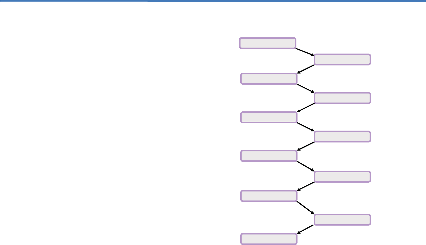
3.1 Installation Procedure
Site Survey
Installation Planning
Link Budget Calculating
Install Outdoor Antenna
Cable Installation
Install Repeater
Install Indoor Antennas
Signal Measure
ment
Gain Adjustment
Test for Call Quality
Trouble Shooting
7 8
3.1 Installation Procedure – Cont.
Check the contents supplied.
Identify a suitable location where you would like to mount the donor
antenna on your roof or at an elevated location, free of any other
antennas or immediate obstructions. Confirm this location has the best
input signal from the cell tower or towers you would like to support.
Ensure the location is properly isolated from the indoor antenna
and at the same time, ensure the cable length supplied is sufficient to
complete your installation.
Install the donor antenna and route the coax to the proposed location for
the indoor base unit. DO NOT COIL UP any excess coax you may have,
including any service loops.
Connect the indoor service antennas, coax and power supply. Power up
the unit and monitor the LED status for errors.
If the donor antenna used is not an omni-directional antenna or the
nearest cell tower location is not known at the time of system
commissioning, then you may need to rotate the donor antenna until the
best signal strength or call quality is achieved on your mobile device,
while making sure the LEDs stay green on the repeater.
We suggest getting someone to help rotate the donor antenna while you
monitor both your mobile device (Phone or PC Card) and the LEDs on the
repeater at the same time.
If signal oscillation is between 1~4dB then the Alarm LED for the
relevant band will turn amber. Please adjust the DL repeater gain till the
LEDs turn green. (See attenuation adjustment)
If the signal oscillation is between 10-15dB then the Alarm LED for the
relevant band will turn red, and the repeater will then shut down. This is
as a result of not having enough isolation between the donor and
service antennas. In this case attenuate the DL gain on the repeater
and then match the UL gain to the same gain value. (See attenuation
settings for adjustments)
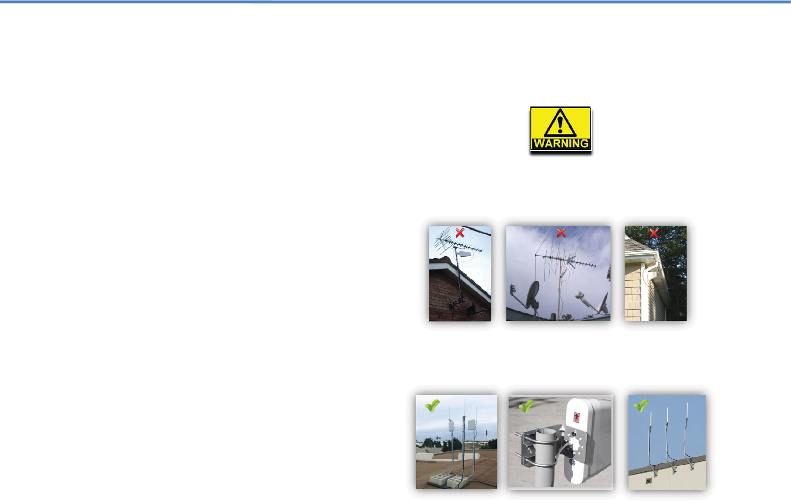
3.2 Antenna Installation and Coax Cable Wiring
We do not recommend installing the donor antenna of your repeater system
in the attic or at the side of a single story building. Doing so will reduce the
quality of the input signal from the cell tower. Also you increase the risk of
signal oscillation taking place, thus having to attenuate the output power of
your repeater.
Do not install the donor antenna near high voltage power lines.
Please take the necessary safety measures when working on heights.
Do not mount near or in the path of other antennas or satellite dishes.
It is recommended that you mount your donor antenna in a spot that is
free of any immediate obstructions. Making use of a pole or mounting
bracket is recommended for optimum antenna performance.
9 10
3.3 Manual Gain Adjustment ~ UL / DL
In order to meet and maintain safe environmental conditions for seamless
network integration, this repeater is equipped with an LCD interface that
allows you to manually control the Uplink / Downlink gain individually. The UL
/ DL attenuator control range is from 0dB to -31dB by 1dB increments.
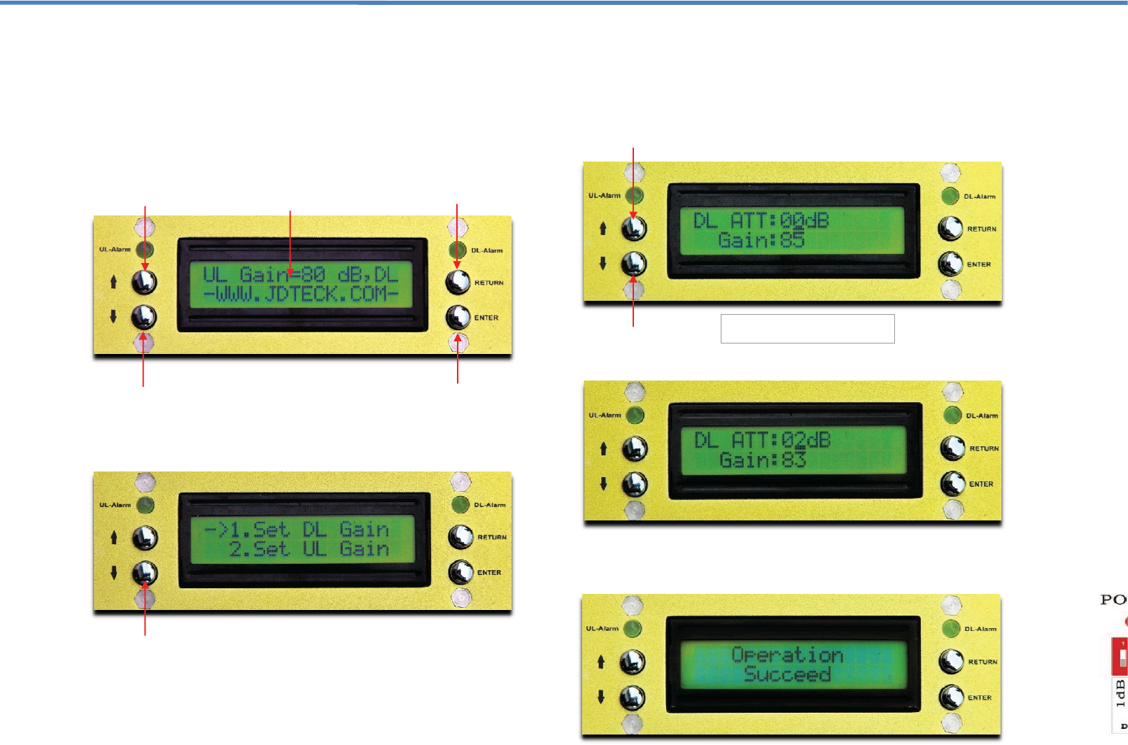
When your repeater is switched on, the LCD screen will display the current
UL and DL gain values and output power setting in a scrolling sequence.
Click the ENTER button to access the menu to add or remove attenuation.
Click the UP or DOWN navigation button to access the desired band you
would like to attenuate. (UPLINK or DOWNLINK)
3.3 Manual Gain Adjustment ~ UL / DL – Con’t.
Click the ENTER button again after you have selected the desired band you
would like to attenuate. This will then bring your prompt to the current
attenuation value. (Default is 0dB) You can then use either the UP or
DOWN navigation buttons to add the desired amount of attenuation.
The following example shows a value of 2dB has been selected.
Please note: For the selected value to take effect, you must press the
ENTER button after, or it will not register. You will then get a confirmation
response when the change was successful.
Down Navigation Button
Enter / Select Button
Return Button
The default of UL/DL gain
attenuator is at 0dB. (Full Power)
Up Navigation Button
Active Power Status Scrolling
Down Navigation Button
Down Navigation Button
Up Navigation Button
11
12
3.3 Manual Gain Adjustment ~ UL / DL – Con’t.
After the change has been made, monitor the DL alarm LED to see if it’s
green or if further attenuation is needed. If the DL LED remains a solid green,
then be sure to match the UL gain to the same dB value.
In some deployments, the end user may decide to have a stronger UL gain if
the location of the repeater is very far from the cell tower. In this instance, it
would be best not to exceed a 5dB difference on the DL gain as this could
affect the optimum performance of the repeater’s bandwidth capacity.
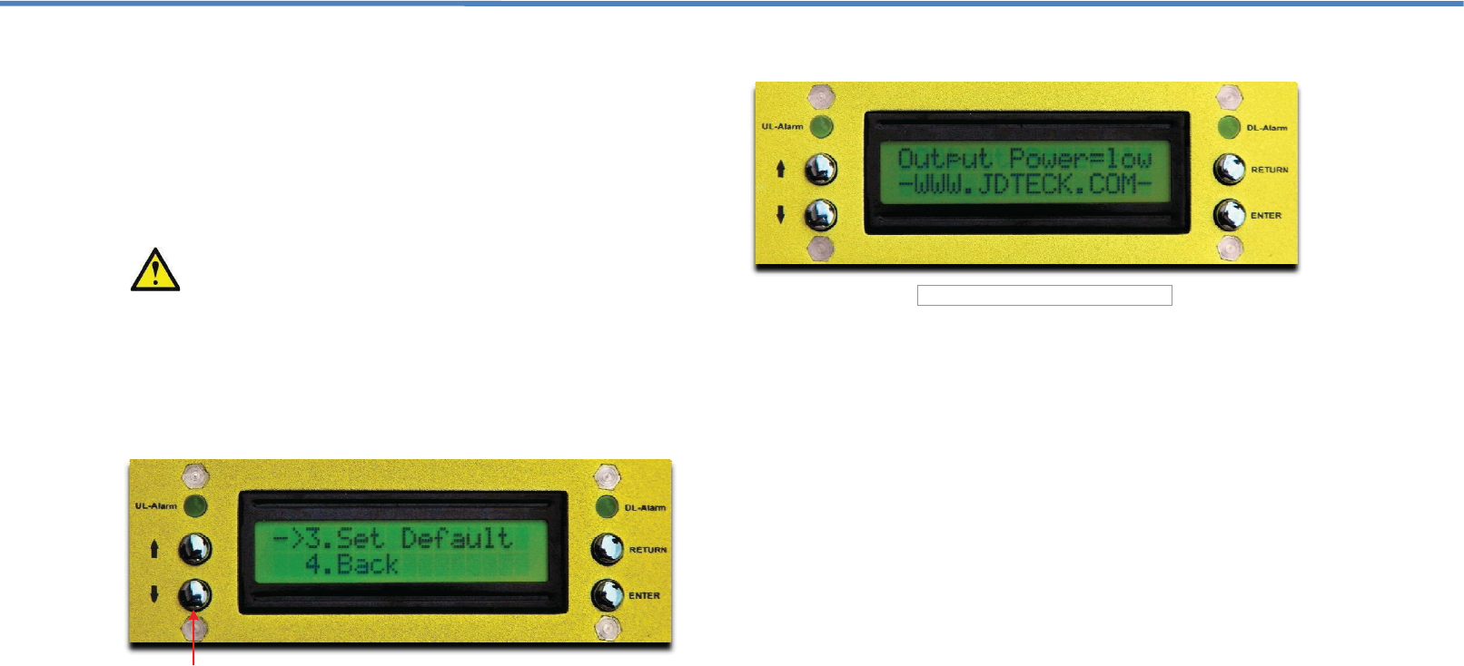
Main Menu
When in the main menu, if you continue to scroll down the LCD will display
options 3 & 4. When selected, option 3 will allow you reset the dB values to
factory default. (No Attenuation = Full Power).
Option 4 simply allows you to exit the main menu back to the home screen.
Click the ENTER button to access any selection.
Output Power
Another neat feature about the LCD Interface on this repeater is that in
addition to the current UL and DL gain values that scrolls on the home
screen, it also displays the active output power level of the unit. This can be
used as an indicator to determine how strong an input signal is being
received by the repeater. For example if the input signal is weak, the output
power will display “Output Power = Low”.
If your donor antenna is in the best location for receiving a good input signal
and the Output Power is still Low, then it could be that you either have a
compromised connector on your input coax cable, or that you need to add a
pre-amp to the system to boost the weak input signal.
3.3 Manual Gain Adjustment ~ UL / DL – Con’t.
When do you adjust the Repeater Gain?
This repeater is equipped with an alarm feature that monitors the input gain.
If the input gain is too high, the Alarm LED will change color from green to
either, amber or red indicating the intensity or the error. High input gain can
occur if the donor antenna is in a location where the receive signal strength
(RSSI) from the cell tower is extremely good (-50dB or better) or if signal
oscillation is taking place. Signal Oscillation is when the amplified signal
from the indoor service antenna is being received back into the donor
antenna outside.
To determine what is the cause of your Alarm LED changing color you can
disconnect the indoor antenna / service line from the “INDOOR” port of the
repeater. If the LED does not change to green, then your input signal from
the cell tower is very strong and it is highly recommended you attenuate the
DL gain by 1dB increments till the LEDs turns green again. Then you must
match the same attenuation value to the UL, after which you can connect the
indoor antenna / service line again.
If after reconnecting the indoor antenna or service line, the LED changes
back to amber or red then signal oscillation is taking place. This is the result
of your indoor and outdoor antennas being too close to each other and
should therefore have more separation.
When complete, try making some test calls throughout the desired area of
coverage while monitoring the LEDs to see if it changes color. If you are
showing strong signal strength but your calls are not going through, it could
be that you need to attenuate your uplink gain a bit more. Keep in mind
however that you do not want to have more than a 5dB difference between
the uplink and downlink values for optimum system performance.
We encourage you to call us when commissioning your repeater system to
make sure you have seamless integration to the cellular network. We are
always happy to help. 1-866-4-JDTECK (53-8325).
Avoid putting more than a 5dB difference between the Uplink and Downlink.
Down Navigation Button
13 14
Repeater not receiving a good input signal.
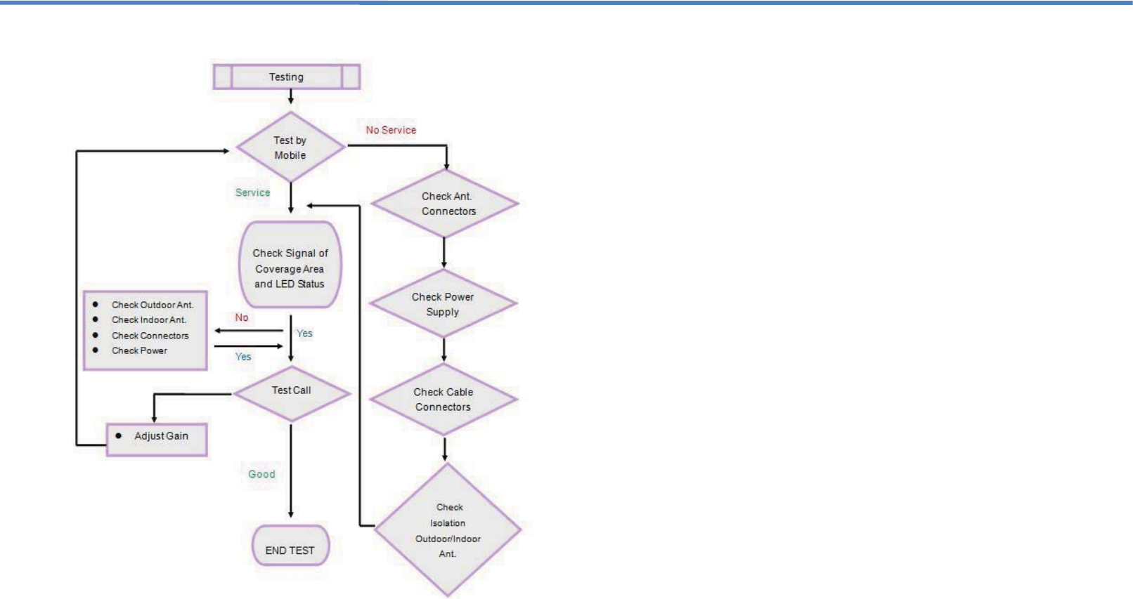
3.4 Testing
3.5 Troubleshooting
Q1. Why is there still no signal after installing the equipment?
Answer:
1. Check the power on repeater and power supply.
2. Check the connector of outdoor antenna is tight or not.
3. Check the connectors of RF cable are tight or not.
4. Check the outdoor signal is strong enough or not.
5. Check to make sure the antenna is installed correctly.
6. Check the connector of indoor antenna is tight or not.
7. Check the cable type is suitable or not.
Q2. Why the signal strength is too weak on the edge of area?
Answer:
1. Check the outdoor signal and antenna direction.
2. Check repeater is full gain or not.
3. Check all of the connectors are tight.
4. Change the location of outdoor/indoor antenna.
5. Check the cable type is suitable or not.
6. Deploy more indoor antennas.
Q3. Why can’t I make a call after installation, even though I can
detect a signal?
Answer:
1. Check LED status of repeater to make sure alarms are green.
2. Change the location of outdoor / indoor antenna.
3. Reduce the UL gain of the repeater.
Q4. The signal is not stable after turning on the repeater power.
Answer:
1. Check to see if the outdoor signal is stable or not.
2. Check the location of the donor antenna. Too close to other antennas.
3. Check the RF cable is broken or not and has no coils.
4. Confirm direction of donor antenna in relation to cell tower.
Q5. Why is the LED on the front of the repeater not lit?
Answer:
1. Check the power source is normal or not.
2. MUTE feature is active. Attenuate gain of repeater and cycle power.
15 16
Mechanical Specifications
Input / Output Port N-Female
Impedance 50 Ω
Dimensions (W x D x H) 250 x 330 x 53mm
Weight ≤4.9Kg (10.8 Lbs)
Operating Temperature -10°C ~ 50°C
Environment Conditions IP40
Switching Adapter Input AC 100~240V, Output DC 12V / 6A
___________
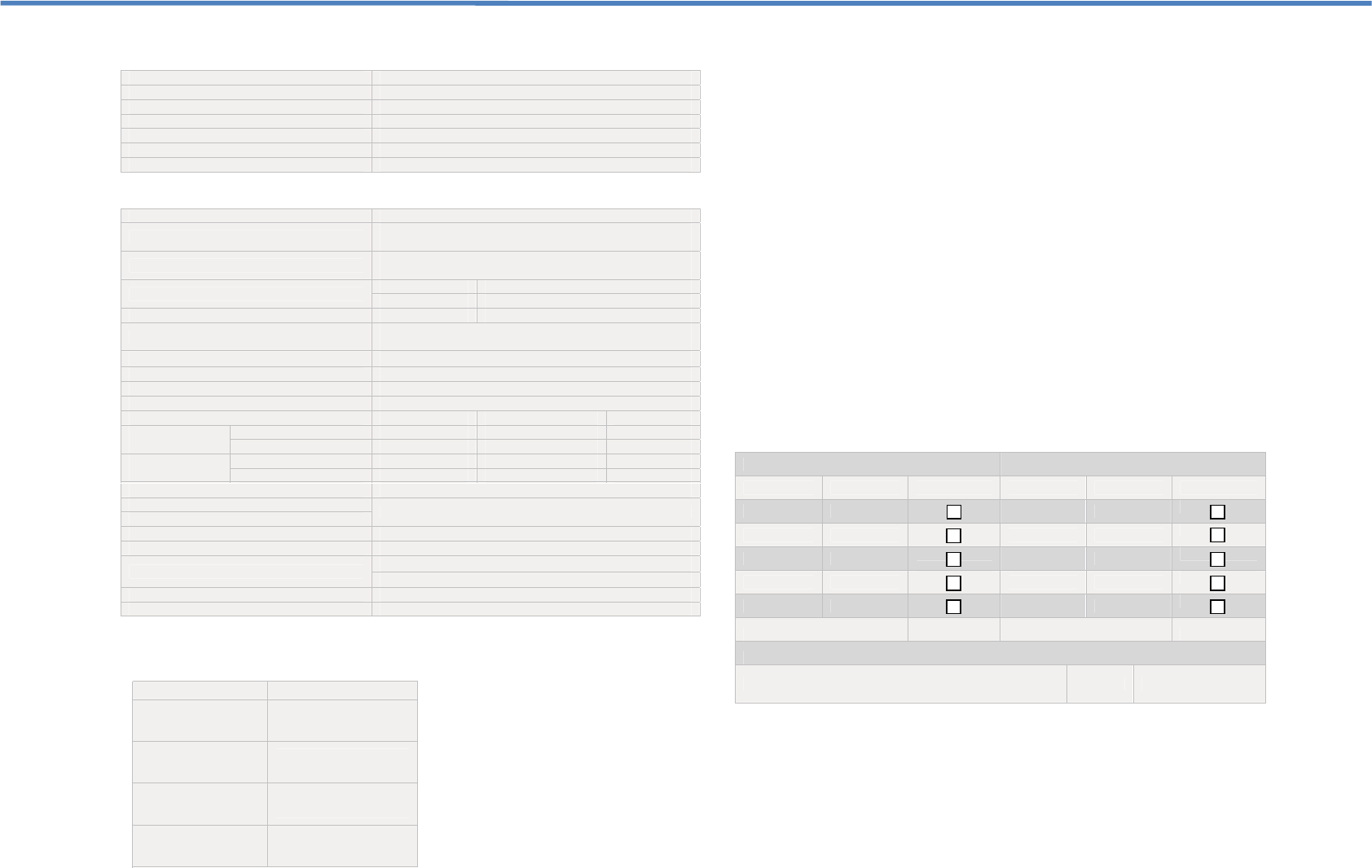
Record your repeater settings here.
Downlink Uplink
Dip Switch Value ON Dip Switch Value ON
1 1dB 1 1dB
2 2dB 2 2dB
3 4dB 3 4dB
4 8dB 4 8dB
5 16dB 5 16dB
Total dB Attenuated …………... Total dB Attenuated …………...
Adjusted By: ___________________________________ Date: ……./……/…………
FCC Statement
PLEASE NOTE: It is normal for your repeater to be quite warm while in use.
FCC Radiation Exposure Statement:
This equipment complies with FCC radiation exposure limits set forth for an
uncontrolled environment . This equipment should be installed and operated
with minimum distance 20cm between the radiator& your body. This
transmitter must not be co-located or operating in conjunction with any other
antenna or transmitter.
Frequency Specifications
Model JD60-9-LC
FCC ID SQXJD60-9-AWS-LC
Filter Bandwidth
AWS 45MHz
Max total output power Downlink Uplink
29dBm 20dBm
Max. Gain 85dB 80dB
Gain Flatness CDMA
AWS ≤6dB
AGC Range ̱15dB ୈauto shut off after 15dB
Maximum Input Power 0dBm
Gain Control Range(MGC) ≥31dB in step of 1dB by LCD menu
V.S.W.R ≤2
AWS|WCDMA
Output Inter-
modulation
9KHz~1GHz ≤-36dBm ≤-36dBm
1GHz~12.75GHz ≤-30dBm ≤-30dBm
Spurious
Emission
9KHz~1GHz ≤-36dBm ≤-36dBm
1GHz~12.75GHz ≤-30dBm ≤-30dBm
Modulation Accuracy ≥12.5%
Spurious Emission Mask Meet 3GPP TS 25.143 (V 6.2.0)
Input Inter
-modulation
Peak Code Domain Error ≥-35dB @ Spreading Factor 256
Frequency Stability ≤0.01ppm
ACRR ≥30dBc / 30KHz 㧬±5MHz
≥50dBc / 30KHz 㧬±10MHz
Noise Figure (@ max gain) ≤6dB
Group Delay ≤4.5 micro Sec
Model Specifications
Classification Bandwidth Range
A. Frequency Range
(AWS)
1700 / 2100Mhz
DL- 2110-2155 (MHz)
UL -1710-1755 (MHz)
17 18
Any Changes or modifications not expressly approved by the party responsible
for compliance could void the user's authority to operate the equipment.