JENOPTIK Robot 590106 Doppler Radar Sensor User Manual Quick Start Guide
JENOPTIK Robot GmbH Doppler Radar Sensor Quick Start Guide
Quick Start Guide
OPTISCHE SYSTEME | LASER & MATERIALBEARBEITUNG | INDUSTRIELLE MESSTECHNIK | VERKEHRSTECHNIK | VERTEIDIGUNG & ZIVILE SYSTEME
Quick Start Guide
RRS24F-SD2/20
FCC ID: QJJ-590106
IC ID: 8226A-590106
Robot/590106/250610/En/A

RRS24F-SD/20
Robot/590106/250610/En/A 2
Legal notice
JENOPTIK Robot GmbH
Opladener Strasse 202
D-40789 Monheim am Rhein
Germany
Telephone: +49 2173 3940-0
Fax: +49 2173 3940-169
www.jenoptik.com/ts
Legal notes
Contents
We strive to provide information that is correct, up to date and complete, and
we have carefully prepared this document. Still, we cannot give any kind of
warranty whatsoever for said information. We expressly exclude any liability for
damage and consequential damage in any way related to the use of this docu-
ment. We reserve the right to modify the documented products and product in-
formation at any time.
Data protection
The user as the owner of the data is responsible for the protection of any per-
sonal data that were created with the system. This applies particularly to the
storage, transmission, blocking and deletion of personal data. The user must
comply the applicable data protection regulations that are in force in the coun-
try where the user is registered. ROBOT Visual Systems GmbH cannot be held
liable for any consequences resulting from misuse of the data or from offences
committed by the user against the law with regard to the protection of personal
data.
Copyright/Industrial property rights
Any texts, images, graphics and the like, as well as their arrangement, are sub-
ject to protection under copyright and other laws of protection. The reproduc-
tion, modification, transmission or publication of any part of this document or of
the entire document in any form is prohibited.
The document serves the exclusive purposes of information and of operation in
accordance with the regulations and does not justify any counterfeiting of the
products concerned.
All signs contained in this document (protected marks, such as logos and trade
names) are the property of ROBOT Visual Systems GmbH or of third parties
and must not be used, copied or distributed without prior written consent.

RRS24F-SD/20
Robot/590106/250610/En/A 3
Contents
1 Important information ..................................................................................................... 4
1.1 Obligation to Read ..................................................................................................................... 4
1.2 Target Group.............................................................................................................................. 4
1.3 Storing the document................................................................................................................. 4
1.4 FCC / IC Compliance Information.............................................................................................. 4
2 Product Information ........................................................................................................ 5
2.1 RRS24F-SD2/20 Functional Description ................................................................................... 5
2.2 Technical Data RRS24F-SD2/20............................................................................................... 6
3 Sensor Location .............................................................................................................. 7

RRS24F-SD/20
Robot/590106/250610/En/A 4
1 Important information
This document is designed to familiarize the user with the unit so that the unit
is used for its correct purpose. This document provides important information.
Following these instructions helps to avoid hazards and repair costs, and to re-
duce failure times.
1.1 Obligation to Read
This document must be carefully read, understood and applied by all persons
who are involved in the operation of the unit or system. For your own safety,
please read the Safety Instructions section with particular care. Following all
instructions exactly will ensure that neither yourself nor any other person is put
at risk and will avoid damage to the unit or system. Please contact the cus-
tomer service of ROBOT Visual Systems GmbH if you have any questions that
are not dealt with in this document.
1.2 Target Group
This document is aimed at qualified staff that has been specially trained to op-
erate the unit.
1.3 Storing the document
This document must be kept for future use and made available to the staff at
any time. Excerpts are not allowed.
1.4 FCC / IC Compliance Information
The K-Band RADAR device supplied with this product has been tested and
found to comply with the limits for a Class A digital device, pursuant to Part 15
of the FCC Rules and with RSS-210 of Industry Canada.
These limits are designed to provide reasonable protection against harmful in-
terference when the equipment is operated in a commercial environment. This
equipment generates, uses, and can radiate radio frequency energy and, if not
installed and used in accordance with the instruction manual, may cause harm-
ful interference to radio communications. Operation of this equipment in a resi-
dential area is likely to cause harmful interference in which case the user will
be required to correct the interference at his own expense.
Operation is subject to the following two conditions:
1. this device may not cause harmful interference, and
2. this device must accept any interference received, including interference
that may cause undesired operation.
Changes or modifications made to this equipment not expressly approved by
JENOPTIK Robot GmbH may void the FCC authorization to operate this equip-
ment.
RRS24F-SD/20
2 Product Information
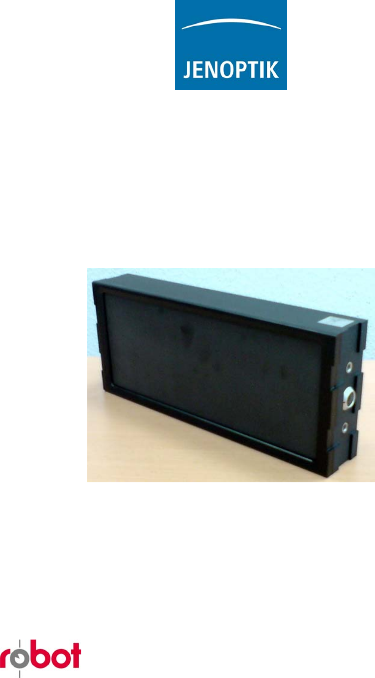
The RRS24F-SD2/20 is a K-Band RADAR sensor intended for the monitoring
of vehicle speed in road traffic. Features of the sensor are:
− Operates within the 24GHz ISM band.
− Transmitter power < 20dBm e.i.r.p., R&TTE conform.
− Continuous Wave (CW) transmission.
− Peak power transmission at 20°l to the front face of the product (20°
squint angle).
− Horizontal beam width, within -3dB limits, of ±2,5°.
− Vertical beam width, within -3dB limits, of ±10°.
− Speed in km/h, vehicle duration in meter, distance to vehicle in deci-
meter and vehicle direction for each measured vehicle.
− Single cable for power and communication.
− Communication using proprietary message protocol over standard
‘232 / ’422 serial interface.
Typically the sensor is connected to an intelligent camera system that provides
power and control. When activated the sensor sends a message to the camera
in response to vehicles passing through its beam. Each message is analyzed
in the camera and may trigger the recording of an evidence photograph.
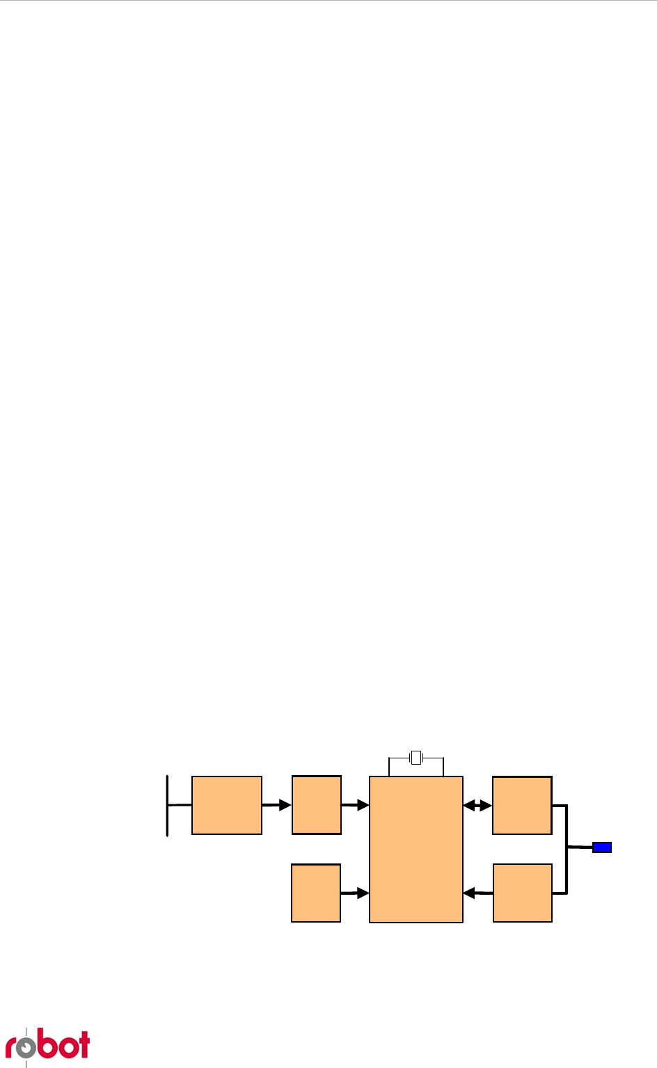
2.1 RRS24F-SD2/20 Functional Description
The RRS24F-SD2/20 includes all components necessary for traffic speed
monitoring in a single robust waterproof enclosure. Using a simple propriety
command protocol the sensor can be configured as required by the measure-
ment location. Once activated, the internal CPU translates the complex Dop-
pler signal at the output of the transceiver into verified values of vehicle speed,
distance, duration and direction. All valid measurements are forwarded auto-
matically to the host using the serial interface. Only a single connection cable is
required.
The sensor interface is optimized for use with an intelligent camera system
from JENOPTIK Robot GmbH.
IVS-157_V2_
squint
CPU
Serial
Int e r fa c e
ADC
System
monit o r
Power
supply
K-Band A ntenna
and Transceiver
Processor with
Quartz stabilized
clock
'232 / '422 Serial
Int e r f a c e
Connector to
Host System
Robot/590106/250610/En/A 5

RRS24F-SD/20
Robot/590106/250610/En/A 6
K-Band Antenna and Transceiver
IVS-157_V2_squint K-Band antenna and transceiver integrates the following
parts:
− Patch array structure with a constant beam form and direction.
− K-Band transmitter with voltage controlled oscillator frequency.
− Low noise receiver and quadrature mixer.
− Dual base-band outputs of the recovered Doppler signal.
The direction of maximum transmitter power is normal to the face of the sen-
sor. Measured between points 3dB below peak power, the beam width is ±2,5°
in the horizontal direction and ±10° in the vertical direction. All side-lobes
measured in the horizontal direction are at least 20dB below peak transmitter
power.
The transmitter is active only when the sensor is placed in measurement mo-
dus by the host (camera).
ADC
The dual outputs of the IVS-157_V2 are digitized at a fixed rate. The continu-
ous stream of samples is passed directly to the CPU for processing.
CPU
The CPU searches the stream of samples from the ADC for moving vehicles.
When recognized, its speed and distance are measured throughout its pas-
sage through the Radar beam. On leaving, the acquired measurements are
checked for quality and consistency, then corrected for the angle between ve-
hicle motion and sensor direction (assumed to be 20°).
The verified speed/distance measurement is packed together with the vehicle
duration in the radar beam and its direction. This package is then sent directly
to the camera via the serial interface.
All speed and distance measurements are referenced to a quartz-stabilized
clock.
Serial Interface
The serial interface operates in ‘232 or ‘422 modus, dependent on the connec-
tion cable used.
System Monitor
All supply voltages and the sensor temperature are constantly monitored.
Should any parameter move out of tolerance, the measurement modus is im-
mediately terminated and the transmitter shut down. The sensor than waits for
the fault to be resolved prior to restarting speed measurement.
Power Supply
The supply from the camera is converted and regulated to the various voltages
required by the sensor. All voltages, including the input supply voltage, are
constantly compared to upper and lower tolerances. Operation of the sensor is
only possible when all supply voltages are within tolerance.
2.2 Technical Data RRS24F-SD2/20
Measuring range: 10 km/h to 300 km/h
Measuring accuracy: 10 km/h to 100 km/h ± 1 km/h
100 km/h to 300 km/h ± 1%
RRS24F-SD/20
Traffic error limit: 10 km/h to 100 km/h ± 3 km/h
100 km/h to 300 km/h ± 3%
Distance measurement: 1 m to 99 m
Measuring angle: 20° with regard to the roadside border
Squint angle: 20°
Horizontal aperture angle: 5° (half-power width)
Vertical aperture angle: 20° (half-power width)
Sensitivity: 3 levels, selectable by host camera
Direction of measurement: selectable by host camera.
Array Type: IVS-157_V2_squint
Transmitter frequency: 24.1 GHz
Transmitting power: 20dBm e.i.r.p. (R&TTE-conform)
Weight: 2.2 kg
Dimensions (W x H x D): 294 mm x 124 mm x 49 mm
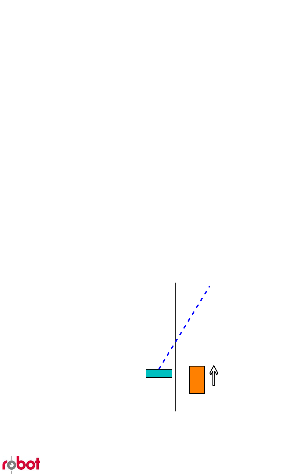
3 Sensor Location
There are several options available for assembly of the sensor at the meas-
urement location. It is well suited to assembly on a tripod at the roadside; in a
vehicle (moving or parked) or to assembly in a fixed radar enclosure. In all
situations the following points are important for dependable and accurate
measurement.
− The sensor assumes that the vehicle to be measured is moving at an
angle of 20° to the radar beam, and corrects the measured speed ap-
propriately. This requires that the RRS24F-SD2/20 be mounted parallel
to the direction of vehicle motion (i.e. road edge).
Sensor
RRS24F-SD2/20
Road Edge
Radar Beam
Radar 20°
to Road Edge
Vehicle moves
parallel to road
edge.
− There must be a clear space of at least four meters in front of the sen-
sor in the direction of measurement.
Robot/590106/250610/En/A 7

RRS24F-SD/20
Robot/590106/250610/En/A 8
− The radar beam must not be obstructed by obstacles such as parked
cars, hedges, piles of sand or snow or similar.
− Measured from the sensor, the road section to be monitored must be
straight for the following distances:
o 30m for a single-lane road.
o 40m for a double-lane road
o 50m for a triple-lane road.
For this purpose a section of road can be considered straight when the shortest
distance between a 35m long straight line and the road verge is not more than
0,1m (radius of band >1600m).
Following assembly at the measurement location the interface cable from the
intelligent camera is attached to the sensor and the measurement modus acti-
vated using the camera GUI.