JENOPTIK Robot 590112 Radar Sensor System User Manual 110415 Draft Introduction
JENOPTIK Robot GmbH Radar Sensor System 110415 Draft Introduction
User Manual
OPTICAL SYSTEMS | LASERS & MATERIAL PROCESSING | INDUSTRIAL METROLOGY | TRAFFIC SOLUTIONS | DEFENSE & CIVIL SYSTEMS
Introduction
RRS24F-ST3
FCC ID: QJJ-590112
IC ID: 8226A-590112
Robot/590112/150411/En/A

RRS24F-ST3
Robot/590112/150411/En/A
2
Legal notice
JENOPTIK Robot GmbH
Opladener Strasse 202
D-40789 Monheim am Rhein
Germany
Telephone: +49 2173 3940-0
Fax: +49 2173 3940-169
www.jenoptik.com/ts
Legal notes
Contents
We strive to provide information that is correct, up to date and complete, and we have carefully
prepared this document. Still, we cannot give any kind of warranty whatsoever for said informa-
tion. We expressly exclude any liability for damage and consequential damage in any way related
to the use of this document. We reserve the right to modify the documented products and prod-
uct information at any time.
Data protection
The user as the owner of the data is responsible for the protection of any personal data that were
created with the system. This applies particularly to the storage, transmission, blocking and dele-
tion of personal data. The user must comply with the applicable data protection regulations that
are in force in the country where the user is registered. ROBOT Visual Systems GmbH cannot be
held liable for any consequences resulting from misuse of the data or from offences committed by
the user against the law with regard to the protection of personal data.
Copyright/Industrial property rights
Any texts, images, graphics and the like, as well as their arrangement, are subject to protection
under copyright and other laws of protection. The reproduction, modification, transmission or pub-
lication of any part of this document or of the entire document in any form is prohibited.
The document serves the exclusive purposes of information and of operation in accordance with
the regulations and does not justify any counterfeiting of the products concerned.
All signs contained in this document (protected marks, such as logos and trade names) are the
property of ROBOT Visual Systems GmbH or of third parties and must not be used, copied or dis-
tributed without prior written consent.

RRS24F-ST3
Robot/590112/150411/En/A
3
Contents
1.1
Obligation to Read ..............................................................................................4
1.2
Target Group......................................................................................................4
1.3
Storing the document..........................................................................................4
1.4
FCC / IC Compliance Information .........................................................................4
2
Product Information .........................................................................................5
2.1
Positioning the Sensor.........................................................................................6
2.2
Connection to SmartCamera system .....................................................................7
2.3
Technical Data RRS24F-ST3.................................................................................7

RRS24F-ST3
Robot/590112/150411/En/A
4
Important information
This document is designed to familiarize the user with the unit so that the unit is used for its cor-
rect purpose. This document provides important information. Following these instructions helps to
avoid hazards and repair costs, and to reduce failure times.
1.1 Obligation to Read
This document must be carefully read, understood and applied by all persons who are involved in
the operation of the unit or system. For your own safety, please read the Safety Instructions sec-
tion with particular care. Following all instructions exactly will ensure that neither yourself nor any
other person is put at risk and will avoid damage to the unit or system. Please contact the cus-
tomer service of ROBOT Visual Systems GmbH if you have any questions that are not dealt with in
this document.
1.2 Target Group
This document is aimed at qualified staff that has been specially trained to operate the unit.
1.3 Storing the document
This document must be kept for future use and made available to the staff at any time. Excerpts
are not allowed.
1.4 FCC / IC Compliance Information
This K-Band RADAR device has been tested and found to comply with the limits for a Class A digi-
tal device, pursuant to Part 15 of the FCC Rules and with RSS-210 of Industry Canada.
These limits are designed to provide reasonable protection against harmful interference when the
equipment is operated in a commercial environment. This equipment generates, uses, and can ra-
diate radio frequency energy and, if not installed and used in accordance with the instruction
manual, may cause harmful interference to radio communications. Operation of this equipment in
a residential area is likely to cause harmful interference in which case the user will be required to
correct the interference at his own expense.
Operation is subject to the following two conditions:
1. this device may not cause harmful interference, and
2. this device must accept any interference received, including interference that may cause
undesired operation.
Changes or modifications made to this equipment not expressly approved by JENOPTIK Robot
GmbH may void the FCC authorization to operate this equipment.
RRS24F-ST3
Robot/590112/150411/En/A
5
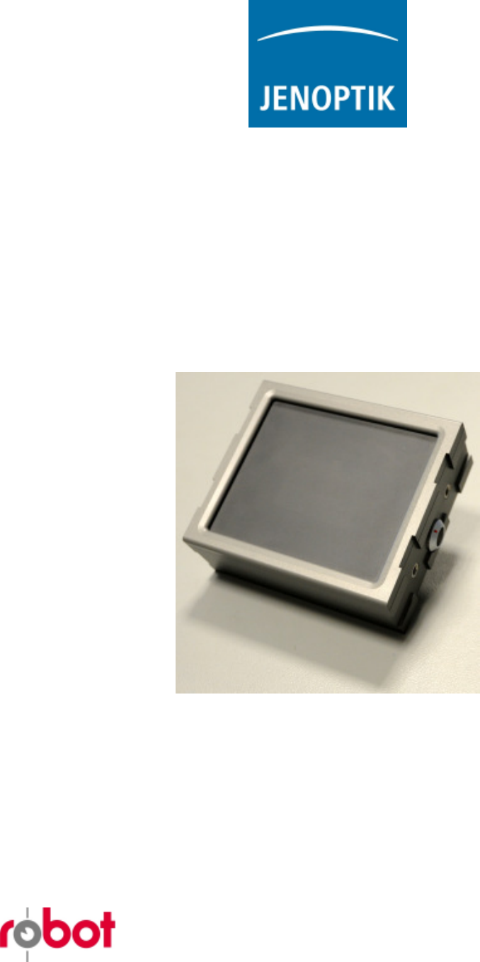
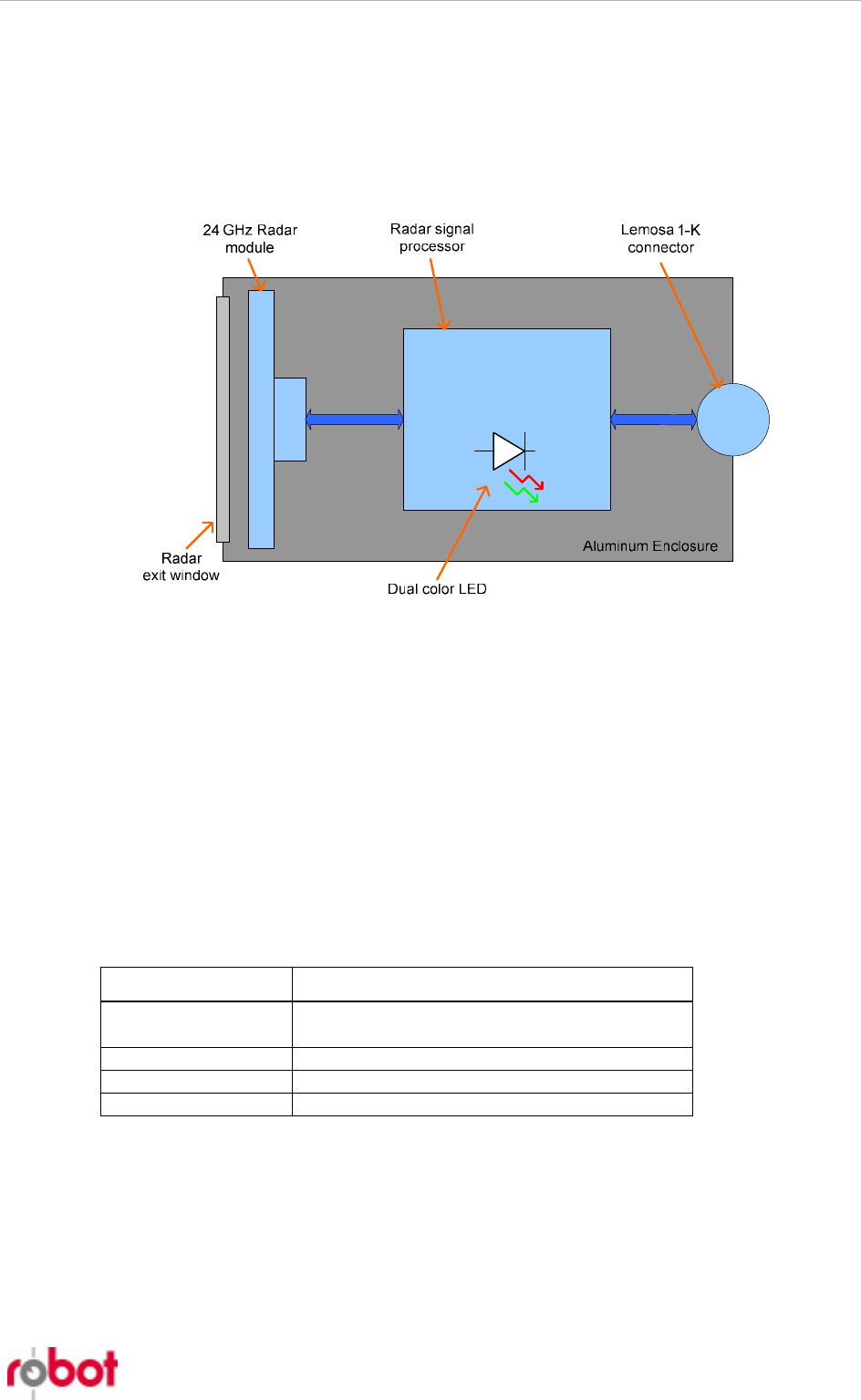
2 Product Information
The sensor includes an advanced 24 GHz Radar module and a high-performance Radar signal
processor, all sealed within a compact and rugged aluminum case. Communication and power is
carried through a single screened cable that locks into an 8-Pol 1-K socket from Lemosa.
The 24 GHz Radar module is mounted directly behind a plastic “window”, or Radom, in the front
face of the enclosure. Microwave energy passes exclusively through this Radom.
Multiple RRS24F-ST3 can jointly monitor traffic from different directions. To avoid interference
each sensor must then operate on a different frequency. Three frequencies are available:
Frequency Set 1: 24,08 GHz
Frequency Set 2: 24,12 GHz
Frequency Set 3: 24.16 GHz
The active frequency set must be selected prior to starting the transmitter. Other frequencies are
not available.
In the rear face is a dual color (red / green) LED visible. The light from this LED is indicative of
the status of the sensor.
LED Color Sensor Status
Orange Sensor power is available; Radar signal proc-
essor is being initialized.
Green Sensor waiting for commands from host
Red blinking Sensor failure
Off Sensor in measurement mode from host
RRS24F-ST3
Robot/590112/150411/En/A
6
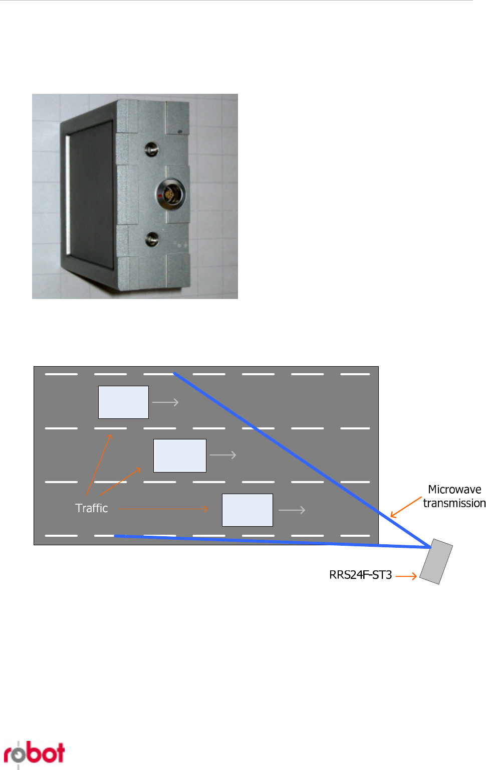
2.1 Positioning the Sensor
Both sides of the enclosure have 20 mm wide
grooves to accept horizontal or vertical guides.
The guides are secured to the sensor by 2x M6
bolts (left / right) in the threaded inserts.
Microwave energy from the Radar module passes
normally through the plastic Radom in the front
of the case (left side in this photograph). The
sensor is typically pointed directly into the traffic
to be monitored.
A typical arrangement of the sensor is next to the road such that the microwave transmission is
directed along the lanes of traffic.
Each vehicle reflects some of the microwave energy back to the sensor, to be received by the Ra-
dar module. The Radar signal processor recovers from the received signal:
− the speed of each vehicle in the field of the microwave transmission.
− the position of each vehicle in a 2D Cartesian co-ordinate system.
Up to 32 vehicles can be simultaneously monitored by the sensor.
Speed and position of each vehicle is updated more than 100x each second. These values contrib-
ute to up to 32 tracks, each associated with a specific vehicle. Should a track cross one of multiple

RRS24F-ST3
Robot/590112/150411/En/A
7
user defined trigger lines, then the current speed and position of that vehicle is transmitted auto-
matically to the host – typically a SmartCamera system – for evidence collection.
2.2 Connection to SmartCamera system
The sensor is typically connected directly to a “SmartCamera” system from Jenoptik Robot. All
parameterization and control of the sensor is done using the customized fields of the camera GUI.
A single cable carries the 115,2-kbaud serial interface and provides power to the sensor from the
camera.
For complete information regarding the application of the sensor to traffic monitoring consult the
documentation provided with the SmartCamera system.
2.3 Technical Data RRS24F-ST3
Speed range and accuracy
Speed: 10 km/h to 300 km/h
Accuracy: ± 3 km/h (speed ≤ 100 km/h)
± 3 % (speed > 100 km/h)
Position measurement range
Distance: ≤ 600-meter
Angle: ± 20° from normal
Frequency
Three user selectable frequency ranges are available:
Set 1: 24,08 GHz
Set 2: 24,12 GHz
Set 3: 24,16 GHz
Transmitter
Transmitter
power: < 20dBm (regulated)
Enclosure
Weight: 1 kg
Dimensions: 137 mm x 120 mm x 50 mm
(W x H x D)
IP: IP67