JSF Technologies AB500 CROSSWALK-WARNING DEVICE User Manual 1
JSF Technologies CROSSWALK-WARNING DEVICE 1
USERS MANUAL
Installation Manual
Active Beacon Version 3.x
Manual Revision 2.01
August 2004
safety just got easier
Installer Configurable Features
Up to 8 JSF Active Beacon units can be interconnected in a single
network system
Up to 16 separate network systems can be installed in close proximity
Both JSF Signature (pulsed) and industry-standard MUTCD flash
patterns are supported along with options for alternating the flashing
(e.g. in sync or "wig-wag") between the two light heads of a single JSF
Active Beacon head or between the various units in a network system
Flash duration can be adjusted over a range of 5 to 60 seconds
Battery Capacity and Nominal Rated Usage
The Nominal Rated Usage is 300 activations per day at a flash duration
of 20 second
Beginning with a fully charged battery pack, a JSF Active Beacon unit
will meet the nominal rated usage without any solar charging
FCC Statement - JSF Technologies
This device complies with Part 15 of
the FCC Rules. Operation is subject
to the following two conditions: (1)
This device may not cause harmful
interference, and (2) this device must
accept any interference received,
including interference that may
undesired operation.
This device and its antenna(s) must
not be co-located or operating in
conjunction with any other antenna
or transmitter. End-users must be
provided with specific operating
instructions for satisfying RF exposure
compliance requirements.
Caution: Changes or modifications
to this equipment, not expressly
approved by the manufacturer
could void the user's authority to
operate the equipment.
This equipment complies with
Industry Canada's ICES 003.
Operation is subject to the condition
that This device may not cause
harmful interference.
Cet Apparreil numerique de la Classe
A respecte toutes les exigences du
Reglement sur le material broilleur du
Canada.
M.U.T.C.D. References
Chapter 4K. Flashing Beacons
Section 4K.01 General Design and Operation of Flashing
Beacons
Section 4K.03 Warning Beacon
Section 4K.03 - B. Warning Signs
Section 4K.03 - C. Crosswalks
Section 4K.03 - Standard
Section 4C.06 - Warrant 5, School Crossing
Section 4F.02 - Emergency Vehicle Traffic Control Signals
Installation Procedure Overview
JSF Technologies recommends that customers observe the following 4 steps as part of their JSF Active Beacon installation procedure:
1. Planning. Plan and recording the installation details using supplied JSF Technologies Active Beacon
Installation Record.
2. Configuring. Configure the JSF Active Beacon units by adjusting the network address, flash pattern and
duration via the user accessible rotary switches on the unit controllers.
3. On-site Mechanical Installation. Connect the JSF Active Beacon battery pack to the unit controller and
perform the mechanical installation of the units.
4. Adjustment.
a. Adjust the flash pattern so that the desired synchronized or alternating flash behavior between the
light heads and units is realized.
b. Adjust the flash duration of all the units in network systems that have push buttons connected.
c. Record the final settings of flash pattern and duration in the JSF Technologies Active Beacon
Installation Record.
5. Record Storage. Store all of your JSF Technologies Active Beacon Installation Records for future reference.
Planning
The general guidelines for planning are to :
A. Consider the number of JSF Active Beacon units that will be required in a network system in order to
provide adequate pedestrian warning to approaching vehicles.
B. Consider any network systems that may already exist in close proximity to a new installation and ensure
that a unique network address (0 through 15) can be allocated.
Configuration
Although not absolutely required, for consideration of speed of network system synchronization, JSF Technologies
recommends that the following steps be executed with the all control units disconnected from their respective battery packs.
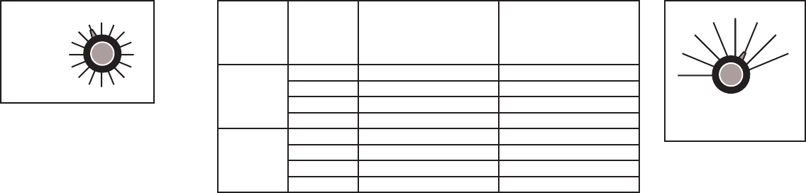
A. Set the network address switch
to the same value (0 through 15)
for all units.
B. Set the flash pattern based on
the following table.
Basic
Pattern
Pattern
Switch
Setting
Flash Synchronization
with other units in
Network
Flash Synchronization
between unit heads
1 and 2
JSF
Signature
(Pulsed)
Industry
Standard
M.U.T.C.D.
in-phase
out-of-phase / alternating
out-of-phase / alternating
in-phase
in-phase
out-of-phase / alternating
out-of-phase / alternating
in-phase
0
1
2
3
4
5
6
7
in-phase
out-of-phase / alternating
out-of-phase / alternating
in-phase
in-phase
out-of-phase / alternating
out-of-phase / alternating
in-phase
0
1
2
3
4
5
6
7
8
9
1
0
1
1
1
2
1
3
1
4
1
5
Network
Address
Fig. 1 - Network Address Selector
Table 1 - Flash Pattern Selection
0
1
2
3
4
5
6
7
Flash Pattern
0
1
2
3
4
5
6
7
Fig. 2 - Flash Pattern Selector
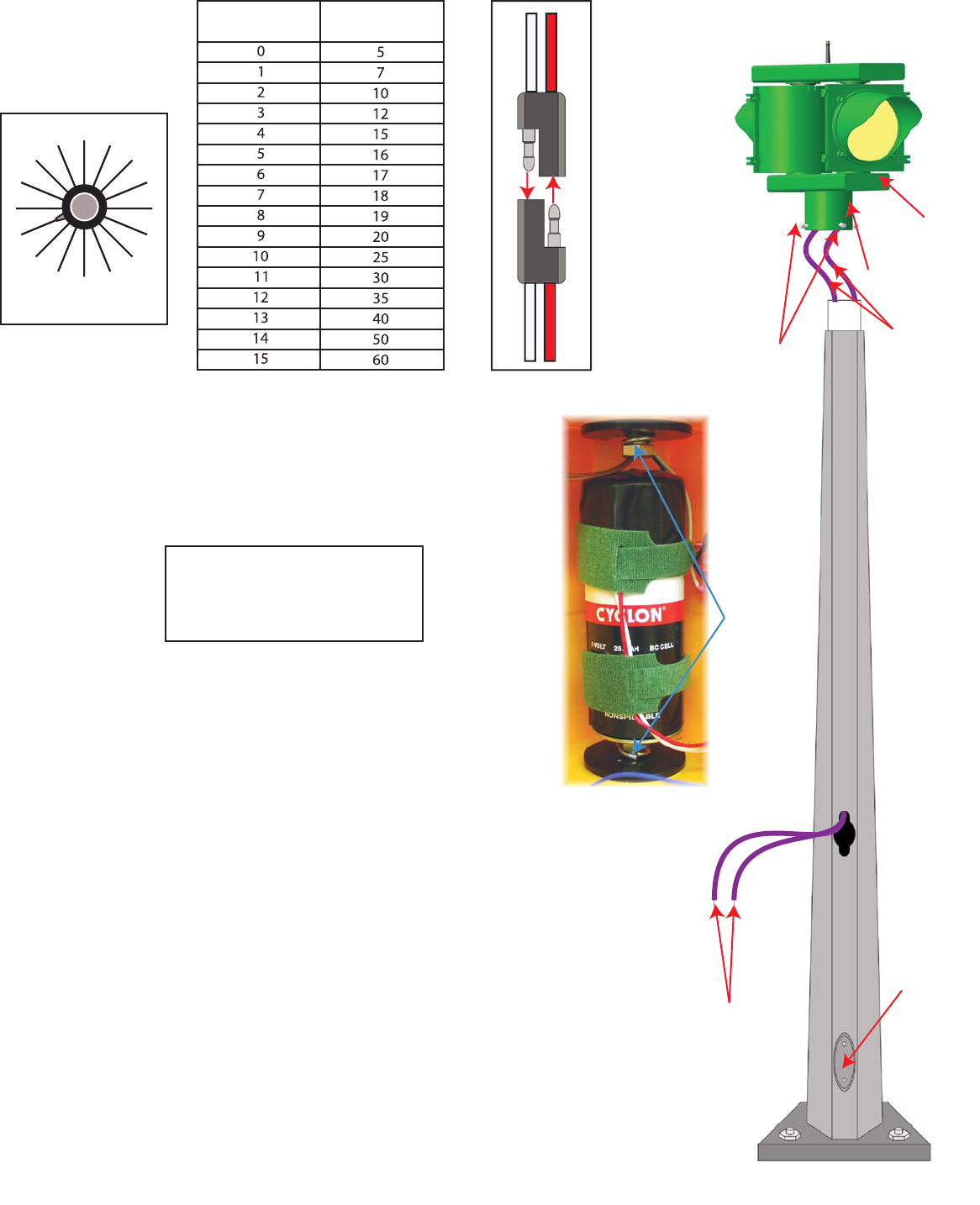
5
7
1
0
1
2
1
5
1
6
1
7
1
8
1
9
2
0
2
5
3
0
3
5
4
0
5
0
6
0
5
7
1
0
1
2
1
5
1
6
1
7
1
8
1
9
2
0
2
5
3
0
3
5
4
0
5
0
6
0
Duration (In Seconds)
C. Set the flash
duration of all units to
the anticipated
required value based
on the following table:
Flash Duration
Switch Setting
Duration
(seconds)
Fig.3- Flash Pattern Selector
Table 2 - Flash Duration Selection
Mechanical Installation
Please note: these installation notes assume that the flash pattern, flash
duration, and network address have all been configured to the desired
setting.
Fig. 4 - Battery Connectors
3/4" crescent wrench
1/2" socket or crescent/box wrench
Robertson #2 (red) screwdriver
Wire strippers/crimpers (for PED Button)
Tools Required
E
.
P
P
ED B
utton
Con
n
n
ect
i
o
n
Wi
r
res
-
Co
nn
ect
T
o
S
Sta
n
da
r
d
PE
D
D
B
utto
n
.
Po
l
l
arit
y
no
t
im
p
p
ortant
.
C.
Set
Sc
r
e
w
s
D
.
PED B
utton
Co
nn
ect
i
on
Wires
(
stored i
n
r)
mountin
g
colla
r
ar
B. Mountin
g
Coll
a
A. Si
g
nal Hea
d
F
.
R
e
m
o
v
ab
l
e
o
r
.
h
a
n
d
-h
o
l
d
doo
Fi
g
. 6- Installation In Detai
l
1. Connect the battery connector in each head. See Figure 4.
Standard practice is to connect the Primary Head (the enclosure that
contains the control box) first before connecting the other head(s).
2. Uncoil the purple PED button wires that are packed inside the
mounting collar. To ease installation, attach the two purple PED
button wires to a weighted object to allow the wires to travel easily
through the signpost.
3. Raise the assembly to the top of the post while feeding the wires
down through the sign post. Mount the assembly to the post using
the mounting collar.
4. Orient the bracket to be parallel to the roadway. Tighten the four
setscrews on the bracket collar.
5. Adjust the angle of each signal head to be perpendicular to the
road.
6. Tighten the retaining bolts. See Figure 5. Check that the bolts are
tightened enough to bury the teeth on the top and bottom of the
signal head into the gasket.
7. Mount the PED button, feeding the two PED button wires to the
hand hole or to the PED cutout and pull the wire through.
8. Connect the PED button to the wires. Polarity is not important.
Fig. 5 - Retaining Bolts
Retainin
g
B
o
l
ts
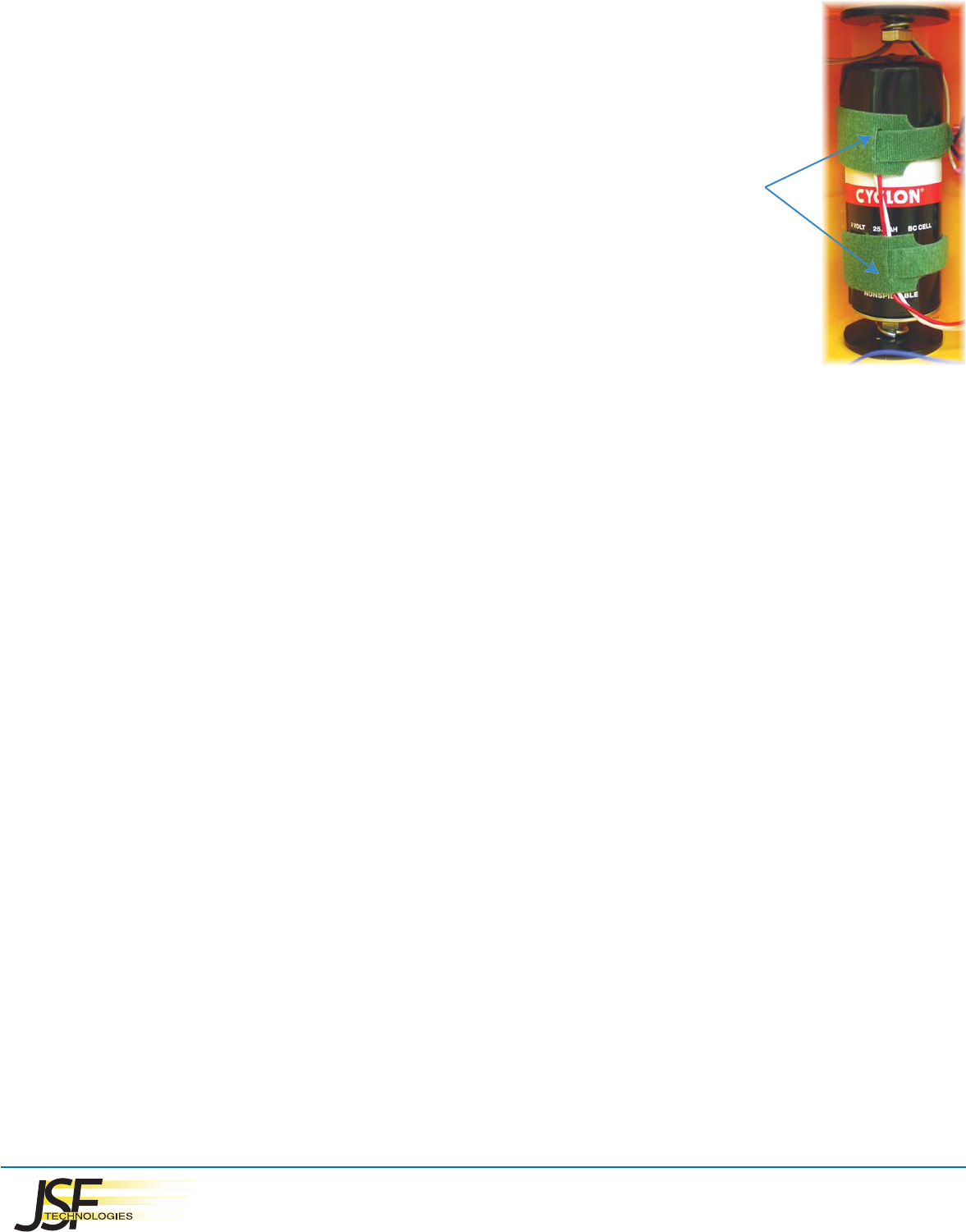
Battery Replacement
The sealed lead-acid battery has a lifespan of approximately 3 years. The battery is a standard model that is
available from JSF Technologies or through the battery manufacturer.
1. Disconnect the battery's power connector.
2. Release the battery's retaining straps. See Figure 8.
3. Installation is the reverse of removal.
Fig. 8 - Battery and Straps
Retaining
Straps
Warranty
JSF Technologies warrants its products against defects in materials and workmanship for a
period of one year from the date of purchase. Products that are returned the JSF
Technologies will be repaired or replaced at the discretion of JSF. Shipping costs are not
included. Products that have misused, vandalized, or struck by a vehicle are not covered by
this warranty. This warranty excludes batteries.
Troubleshooting
If the problem behavior you are experiencing is not covered below, please visit www.jsftech.com and refer to our frequently asked
question page or contact us via e-mail at info@jsftech.com.
Problem: Pushing the push-button on one unit does not cause all the other units in the network system to flash.
Potential solutions:
1) If units were powered up before bringing them to installation site, disconnect and then reconnect their battery packs, then wait for 7 minutes.
2) If units have just been installed, wait for 7 minutes after installation to allow all devices in the network to complete synchronization checks.
3) Adjust the network address switch setting so that all units in the network system same network address.
Note: Changing the network address after powering up the unit will cause the associated device to reset. This will be, effectively, the same as
cycling the power.
Problem: A unit in the network system is flashing with a double-pulsed pattern instead of the pattern indicated by the flash pattern switch.
Potential solutions:
1) The stored energy in the battery is low and the unit has entered a power conservation mode.
A) If the unit was installed more than 3 years ago, try replacing the battery.
B) If the site has experienced a long period of low sunlight, monitor the unit daily as the battery should eventually recharge and resume
its normal flash pattern.
C) If the unit is installed in an area of insufficient sunlight, contact JSF Technologies to discuss options for installation of additional solar
panels.
safety just got easier
JSF Technologies
6771 Kirkpatrick Crescent
Saanichton B.C. V8M1Z8 Canada
1-800-990-2454 / f. 1-800-576-7899
info@jsftech.com / www.jsftech.com