JSW Pacific CCD-325LWS Wireless Camera User Manual UserManual 325CW 730R Cover ai
JSW Pacific Corporation Wireless Camera UserManual 325CW 730R Cover ai
Users Manual
User's Manual
Model No.: CCD-325LWS
2.4 GHz Wireless Color Weather-proof
IP44 Camera
PLEASE READ CAREFULLY AND SAVE
This manual contains important information about this product's operation.
If you are installing this product for use by others you must leave this
manual -or a copy- with the end user.
Navigator R
Impoirtant!
Please read this booklet carefully
before installing or using these units.
DANGER-HIGHVOlTAGE- These units
should ONLYbe opened by an authorized
technician ifservice is required,
Safety Precautions
For correct and safe operation of this
system, it is essential that installers, end-
users and service technicians should follow
all safety procedures outlined inthis
manual. Specific Warning and Caution
statements (and/or symbols) are marked on
the units where needed,
Warning and Caution Statements
"WARNING"indicates a situation where
faiilureto followproper procedures can
cause personal injury,
"CAUTION"indicates a situation where
failure to followproper procedures can
cause damage to the equipment.
Federal Communication Commis.fion Interference Statement
This hasheentestedandfoundto withthelimitsfmaClassB device,
pursuanttoPart15oftheFCCRules,These!imit~are toprovidereasonable
interference in II residenti.al installation.
harmful
This generates, uses and can radiate radio ener&}' MId, if oot installed and used in accordance
with the instructions, niay cause harmful interference to radio communications. However, there i$ 00 guarantee
that interference wi.ll nm occur in a particular installation, Ifthis equipment does cau.se harmful interference to
radio or television reception, which can be determined by turning the equipment off and on, the user is encouraged
to try to correct the interference by one of the following measures:
.Reorient or relocate the receiving mtenna.
, Increase the .separation between the equipment and receiver,
Connect the equipmem into an outlet on a circuit different from that to which the receiver is connected.
. Consult the dealer or an experienced radiorrv technician for help.
FCC Caution :Toassurecontinuedcompliance,any or modifications not expressly
approved the party responsible for compli.ance could void the user's authority to operate this equipment
(Example -use only shielded interface cables when connecting to computer or peripheral devices).
This device complies witb Part 15of the FCC Rules.
is to the following two conditions:
(I) Tbis device may not cause harmful interference, and
Tbis device must accept any interference
undesired operation.
including interference tbat may cause
Canada (Industry Canada) :
To prevent radio interference to the licenscnd service (i.e. co-channel Mobile satellite system) this
device is intended to be operated indoors and away from windowa to provide maximum shielding.
Equipment (or its transimit antenna) that is installed outdoor is sUl~jectto licensing.
'1'0 I

Model No.: CCD-325LWS
2.4 GHz Wireless Color
Weather-proof IP44 Camera
Contents
Important Safety Precautions ..................................1
Specifications ............................................................2
Parts Included with This System .............................3
Parts of the System ..................................................3
- Parts of the Camera ..............................................3
Installing the Wireless Color Weather-proof IP44
Camera System ........................................................4
The Auto-Sequence Function ..................................5
Connecting the Receiver to a TV or Monitor ..........5
Troubleshooting Guide ............................................6
Warranty .....................................................................6

1 6
Important Safety Precautions
Please read before Installing
Congratulations on your purchase of the 2.4GHz Wireless Color Weather-proof Camera.
Please read these safety and operating instructions carefully before installing and using this system.
- Keep the camera AC/DC adapter cords out of reach of children.
- Do not place the camera AC/DC adapter cords in a crib or playpen.
- Locate the camera, receiver, AC/DC adapters where there is adequate ventilation. Do not locate the
camera in direct sunlight.
- Do not locate the camera AC/DC adapters near heat sources such as heat registers,
radiators, ovens, furnaces or other appliances with high operating temperatures.
- Do not use with extension cords. Use only the AC/DC adapters provided with this system.
***Note: Use of other adapters may damage the units and void your warranty.
- Only plug components into standard household voltage outlets (110V - 240V AC, 50Hz or 60 Hz).
- Do not place cords from the AC/DC adapters and camera where they can be pinched or
stepped on. Protect the cords by keeping them out of the way of children, pets and routine household
traffic. Do not place heavy objects on power cords or cover cords with rugs or carpet.
- When cleaning, use a DRY, lint-free cloth. Unplug the camera AC/DC adapters before
cleaning. NEVER immerse any components in water and do not spray cleaners or solvents on the
units. Doing so may damage the units or cause electrical shock.
- Unplug the AC/DC adapters from the wall outlet when the system is not in use.
- Mishandling, alterations or modifications not approved by the manufacturer will void the warranty.
CAUTION!
- Connect this unit ONLY to other compatible units. Do not connect it to any other type of alarm or
auxiliary device. Connecting anything else to this unit may damage it or prevent it from operating
properly.
CAUTION!
- Do not paint over the camera.
CAUTION!
- This system uses public airwaves for wireless operation. The sound and video may be broadcast
to and picked up by other 2.4 GHz receiving devices. Conversations and images from other rooms
near the camera may be broadcast and picked up. To protect your privacy.
IMPORTANT!
ACCESSORIES:Do not place weather-proof camera or equipment on an unstable cart, stand or table.
The video monitor or equipment may fall causing serious injury to a child or adult, and serious damage to
the equipment. Wall or shelf mounting should follow the manufacturer's instruction, and should use a
mounting kit approved by the manufacturer.
VENTILATION: Solts and openings in the cabinet and the back or bottom are provided for ventilation and
to ensure reliable operation of the weather-proof camera or equipment and to protect if from overheating.
These openings must not be blocked or covered. The openings should never be blocked by placing the
weather-proof camera on a bed, sofa, rug, or other similar surface. Weather-proof camera or equipment
receiver should never be placed near or over a radiator or heat register. Weather-proof camera or
equipment receiver should not be placed in a built-in installation such as a bookcase unless proper
ventilation is provided.
You should...
1. Check that the power cord(s) for camera are properly
connected.
2. Check that the monitor is turned ON.
3. Wrong AC/DC adapter used. Check if your are using the right
AC/DC adapter.
1. Check the channel switch settings on the both camera
and receiver is in same channel.
2. Signal interference from a microwave oven. Check if a
micro-wave oven is in use or located in the path between
the weather-proof camera. If so, turn it off or move it out of
the path.
3. Signal interference from other signal producing devices.
(a) Identify and eliminate the source of the interference.
(c) Relocate the weather-proof camera closer to each other.
4. Weather-proof Camera and receiver are too far apart.
Troubleshooting Guide
If the Camera
and/or Monitor...
No Power
No sound or picture.
Distorted sound or
picture
1 Year Limited Warranty:
JSW Pacific Corp., the maker of Navigator brand products, warrants that for a period of 1 year from
the date of purchase, this product will be free from defects in material and workmanship. JSW, at its
option, will repair or replace this product or any component of the product found to be defective during
the warranty period. Replacement will be made with a new or remanufactured product or component.
If the product is no longer available, replacement may be made with a similar product of equal or
greater value. This is your exclusive warranty.
This warranty is valid for the original purchaser from the
date of initial purchase with JSW and is not transferable.
This warranty does not cover normal wear of
parts or damage resulting from any of the following: negligent use or misuse of the product, use on
improper voltage or current, use contrary to the operating instructions, disassembly, repair or alteration
by anyone other than JSW or an authorized service center. Further, the warranty does not cover acts
of God, such as fire, flood, hurricanes and tornadoes or any batteries that are included with this unit.
JSW
shall not be liable for any incidental or consequential damages caused by the breach of any
express or implied warranty.
5 2
FCC/CE WARNING
This equipment generates and uses radio frequency energy and if not installed and used properly,
that is, in strict accordance with the manufacture's instructions, may cause interference to radio and
television reception. It has been tested and found to comply with limits for a Class B digital device in
accordance with Part 15 of FCC Rules and CE I-ETS 300 440, which are designed to provide
reasonable protection against such interference in a residential installation. However, there is no
guarantee that interference will not occur in a particular installation. If this equipment does cause
interference to radio or television reception, which can be determined by turning the equipment off
and on, the user is encouraged to try to correct the interference by one or more of the following
measures:
1. Reorient the TV/radio antenna.
2. Relocate the Receiver away from the TV/radio receiver.
3. Plug the Receiver into a different wall outlet so that the Receiver is on a different branch circuit.
4. If necessary, the user should consult the dealer or an experienced radio/television technician for
additional suggestions.
The user may find the following booklet prepared by the Federal Communication Commission helpful:
"How to Identify and Resolve TV Interference Problems." This booklet is available from the US
Government Printing Office, Washington, D.C. 20402, Stock No. 004-000-00345-4.
FCC/CE NOTICE
The user is cautioned that changes or modifications not expressly approved by the manufacturer
could void the user's authority to operate the equipment. Linear radio controls provide a reliable
communications link and fill an important need in portable wireless signaling. However, there are
some limitations which must be observed.
The radios are required to comply with FCC Rules and Regulations as Part 15 devices and CE I-ETS
300 440. As such, they have limited transmitter power and therefore limited range. A receiver cannot
respond to more than one transmitted signal at a time and may be blocked by radio signals that occur
on or near their operating frequencies. Changes or modifications to the device may void FCC and CE
compliance. Infrequently used radio links should be tested regularly to protect against undetected
interference or fault.
Specifications
*Design and specification are subject to change without notice.
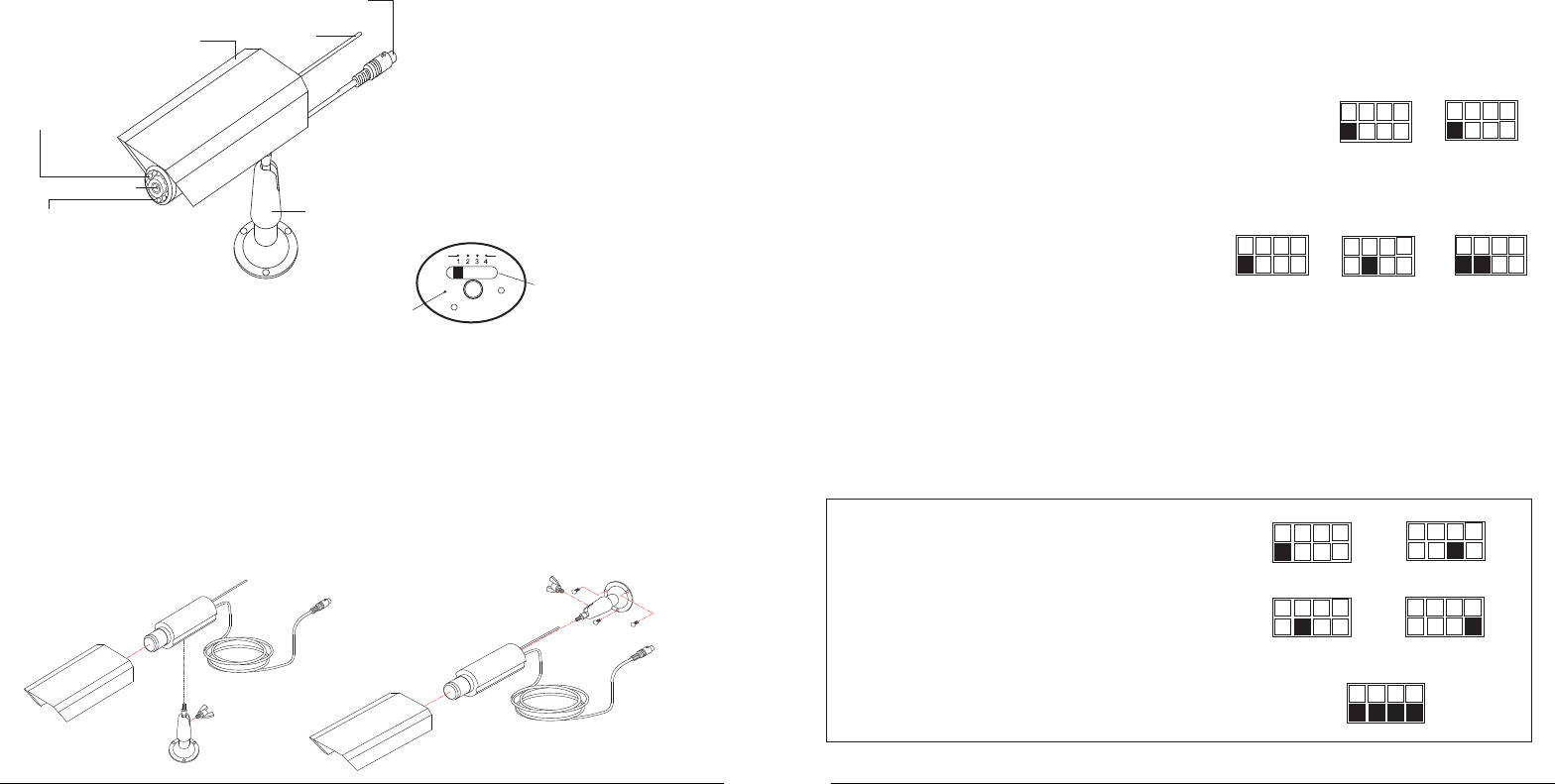
The Auto Sequence Feature
The Wireless Color Weather-proof Camera and Receiver System can be set up to monitor a series of
rooms in a home or office. The receiver can connect up to four cameras on four different channels for
Video reception, and display them in auto sequence. The system has dip-switches for 4 channels to allow
various monitoring options.
When the channel dip-switches are set in the "ON" position, that channel is active on the receiver
and can be seen on the TV or monitor. Channel dip-switches in the "OFF" position are inactive
and will not be shown on the TV or monitor.
The auto-sequence feature is activated
when more than one channel is switched ON.
The channels switched ON will display
on the monitor at five second intervals.
For example, if you have two cameras, one
set to Channel 1 and the other set to channel 3,
the dip-switch on the receiver must be set for
both channels 1 and 3. Then camera one [CH1]
and camera two [CH3] will start to display on the
TV or monitor in sequence at five seconds intervals.
This interval time is preset by the factory and cannot
be adjusted by the user.
To stop the auto-sequence function:
Slide the dip-switch of the channel(s) you do not want displayed
to OFF on both that camera and the receiver. Channels in the
OFF position will no longer be displayed.
1 2 3 4
OF F
ON
Channel Dip-Switch
Diagram Channel 1 ON
1 2 3 4
OFF
ON
Channel Dip-Switch
Diagram Channel 3 ON
1 2 3 4
OFF
ON
Channel Dip-Switch Diagram
Channel 1 & 3 ON
POWER 9V DC, 300mA
CONSUMPTION
CAMERA:
IMAGE SENSOR 1/3" Color CMOS
Image Sensor
RESOLUTION 330 Horizontal TV Lines
LENS Board Lens F6mm / F2.0 (62o)
OPERATING TEMP. 14°F - 122°F
-10°C - 50°C
DIMENSIONS 4" x 1.5" x 1.7"
100 x 38 x 40 mm (approx.)
Illumination
WEIGHT Approx. 140g
< 3 Lux with IR at F2.0 (5 meter)I,R Activated
Automatically
< 0 Lux
Receiver
Camera
3 4
Parts Included with This System
- 2.4 GHz Wireless Color Weather-proof Camera
- Camera Stand
- 9V AC/DC adaptor for the Camera
Parts of The System
Installation
Tools you will need: Pencil, Drill, drill Bits, Phillips-head Screwdriver, Hammer
Installing Mounting Bracket (Camera Stand)
1. Select a mouniting location. Use the mounting bracket as a guide and mark the screw holes
with a pencile.
2. Drill 1/8" pilot holes over the center of each pencil mark. For mounting on drywall or sheet
rock, use the wall anchors provided. Gently tap the anchors into the pilot holes with hammer
until they are flush.
3. Align the bracket over the holes or wall anchors and tighten the screw to secure the bracket
to the wall or ceiling
Installing the Wireless Color Weather-proof
Camera and Receiver System
To install the system, follow these steps:
Weather-proof Camera:
1. Plug the AC/DC adapter cord into the power input jack on the bottom of power cable.
2. Weather-proof camera power will auto on when you plug the AC/DC adapter into a standard
(110V-240V) AC outlet.
1 2 3 4
ON
CH1
Camera 1
1 2 3 4
ON
Camera 2
1 2 3 4
ON
Camera 3
1 2 3 4
ON
Camera 4
1 2 3 4
ON
Receiver
CH2
CH3
CH4
System Setup:
1. Select the channel (Channel 1-4, as indicated on Channel Label) to be used on both the
camera and receiver.
NOTE: Make sure the camera and receiver are set to the same channel (1, 2, 3 or 4).
2. Set the selected channel by gently pushing the dip-switch for that channel to the ON position on
both the camera and the receiver.
For example, to set both the camera and receiver on Channel 1:
(a) Push the Channel 1 dip-switch located on the camera and
the receiver to the ON position.
(b) Make sure the remaining dip-switches are in the OFF
position. In this case, channels 2, 3 and 4 should be in
the OFF position.
If more than one camera is to be installed and operated at the same time:
Simply follow steps (a) and (b) and set the
dip-switches for the other channels on the
camera and receiver to ON.
For example, to operate two cameras: set
Camera 1 to Channel 1 (other channels off),
set Camera 2 to Channel 2 (other channels off),
and on the receiver, set channels 1 and 2 to ON.
See “Camera and Receiver Setting Chart” below for more detailed instructions.
Additional Notice- When installing the camera, check the reception of the receiver before final
installation. Have someone hold the camera in the area to be monitored and another person to
check the reception with your TV or monitor. If interference or other problems occur, refer to the
Troubleshooting Guide.
Camera & Receiver Channel Setting Chart
1. This 2.4 GHz system can be connected with up to 4
channels. Set channels on the camera and receiver
before starting the system.
2. Set camera and receiver channels by gently pushing the
switches with an object such as a pen or pencil to the ON
or OFF position. Use the illustrations shown on the right
as a guide. The switches are inset into the camera and
receiver housings to avoid accidentally changing the
channel settings.
3. The Auto Sequential Scanning feature automatically
activates when more than one switch is set to ON.
4
ON ON ON
1 2 3 4 1 2 3 4 1 2 3
Camera 1
Set to
Channel 1
Camera 2
Set to
Channel 2
Receiver Set
to Channel
1 & 2
ON
1 2 3 4 1 2 3 4
ON
Camera Set to
Channel 1
Receiver Set to
Channel 1
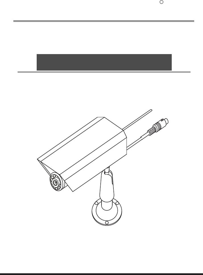
Parts of the Camera
Antenna
Sunshield
11 pcs IR LED
Camera Lens
Power Jack
Camera Stand
CDS Auto Control
for Night Vision
Microphone
Channel Switch