JSW Pacific CCD-402S Wireless Mini Camera User Manual UserManual 6200 Cover ai
JSW Pacific Corporation Wireless Mini Camera UserManual 6200 Cover ai
UserManual.wiki
>
JSW Pacific
>
CCD 402S User Manual
Users Manual
Navigation menu
Upload a User Manual
Namespaces
Wiki Guide
HTML
PDF
Info
Views
User Manual
Discussion / Help
Navigation
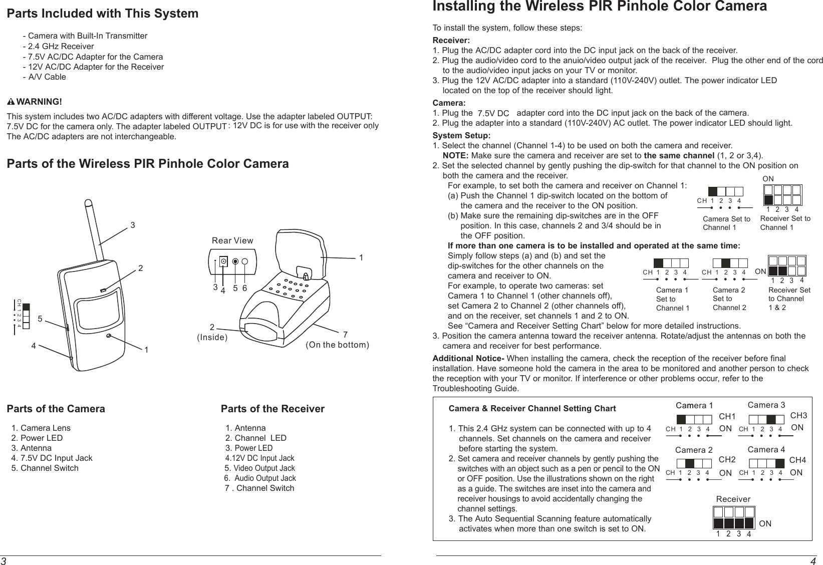
![5 2FCC/CE WARNINGThis equipment generates and uses radio frequency energy and if not installed and used properly, that is, in strict accordance with the manufacture's instructions, may cause interference to radio and television reception. It has been tested and found to comply with limits for a Class B digital device in accordance with Part 15 of FCC Rules and CE I-ETS 300 440, which are designed to provide reasonable protection against such interference in a residential installation. However, there is no guarantee that interference will not occur in a particular installation. If this equipment does cause interference to radio or television reception, which can be determined by turning the equipment off and on, the user is encouraged to try to correct the interference by one or more of the following measures: 1. Reorient the TV/radio antenna. 2. Relocate the Receiver away from the TV/radio receiver. 3. Plug the Receiver into a different wall outlet so that the Receiver is on a different branch circuit. 4. If necessary, the user should consult the dealer or an experienced radio/television technician for additional suggestions.The user may find the following booklet prepared by the Federal Communication Commission helpful: "How to Identify and Resolve TV Interference Problems." This booklet is available from the US Government Printing Office, Washington, D.C. 20402, Stock No. 004-000-00345-4.FCC/CE NOTICEThe user is cautioned that changes or modifications not expressly approved by the manufacturer could void the user's authority to operate the equipment. Linear radio controls provide a reliable communications link and fill an important need in portable wireless signaling. However, there are some limitations which must be observed.The radios are required to comply with FCC Rules and Regulations as Part 15 devices and CE I-ETS 300 440. As such, they have limited transmitter power and therefore limited range. A receiver cannot respond to more than one transmitted signal at a time and may be blocked by radio signals that occur on or near their operating frequencies. Changes or modifications to the device may void FCC and CE compliance. Infrequently used radio links should be tested regularly to protect against undetected interference or fault.Rotating the Antennas for Best PerformanceThis system broadcasts its high-quality audio and video using directional antenna. The antenna can rotate in either clockwise or counterclockwise directions to obtain the best signal and picture clarity. In most situations, additional adjusting of the antenna may be necessary to get optimal performance. If the camera and receiver are less than 10 feet apart, leave the antenna in the closed (down) position. See the instructions shown on the right to rotate the antenna. The Auto Sequence FeatureThe Wireless Color Monitoring System can be set up to monitor a series of rooms in ahome or office. The receiver can connect up to three cameras on three different channels forboth Audio/Video reception, and display them in auto sequence. The system has dip-switchesfor 4 channels to allow various monitoring options.When the channel dip-switches are set in the "ON" position, that channel is active on the receiverand can be seen on the TV or monitor. Channel dip-switches in the "OFF" position are inactive and will not be shown on the TV or monitor.The auto-sequence feature is activated when more than one channel is switched ON. The channels switched ON will display on the TV or monitor at three second intervals. For example, if you have two cameras, one set to Channel 1 and the other set to channel 3, the dip-switch on the receiver must be set for both channels 1 and 3. Then camera one [CH1] and camera two [CH3] will start to display on the TV or monitor in sequence at three seconds intervals. This interval time is preset by the factory and cannot be adjusted by the user.To stop the auto-sequence function:Slide the dip-switch of the channel(s) you do not want displayed to OFF on both that camera and the receiver. Channels in the OFF position will no longer be displayed.270ºUp/Down 84ºReceiverChannel Dip-SwitchDiagram Channels 1 & 3 ON4SpecificationsRECEIVER:RECEIVING DISTANCE Up to 300 Feet (Clear Line of Sight)VIDEO OUT 1 Vp-p 75 OhmAUDIO OUT 1 Vp-p 600 OhmPOWER SUPPLY 12V DC, 200 mAOPERATING TEMP. 32°F - 122°F 0°C - 50°CWEIGHT Approx. 0.3LB/146.2gCAMERA:IMAGE SENSOR 1/3" Color CMOS Image SensorRESOLUTION 330 Horizontal TV LinesLENS 6mmOPERATING TEMP. 32°F - 122°F 0°C - 50°CDIMENSIONS Approx. 2.1" x 1.6" x 6.2" 5.5 x 4 x 16cm (LxWxH)WEIGHT Approx. 0.2LB/100gDIMENSIONS Approx. 3.6" x 2.3" x 3.6" 9.6 x 6.2 x 9.5cm (LxWxH)POWER SUPPLY 7.5V DC, 500mAPIR Viewing Angle > 75° PIR Viewing Distance >5m ONCH1CCaammera 11ONCamera 3CH3CH 1 2 3 4 CH 1 2 3 4](https://usermanual.wiki/JSW-Pacific/CCD-402S/User-Guide-456787-Page-5.png)