JSW Pacific CCD-602S Wireless Camera User Manual CCD 602S
JSW Pacific Corporation Wireless Camera CCD 602S
UserManual.wiki
>
JSW Pacific
>
CCD 602S User Manual
Users Manual
Navigation menu
Upload a User Manual
Namespaces
Wiki Guide
HTML
PDF
Info
Views
User Manual
Discussion / Help
Navigation
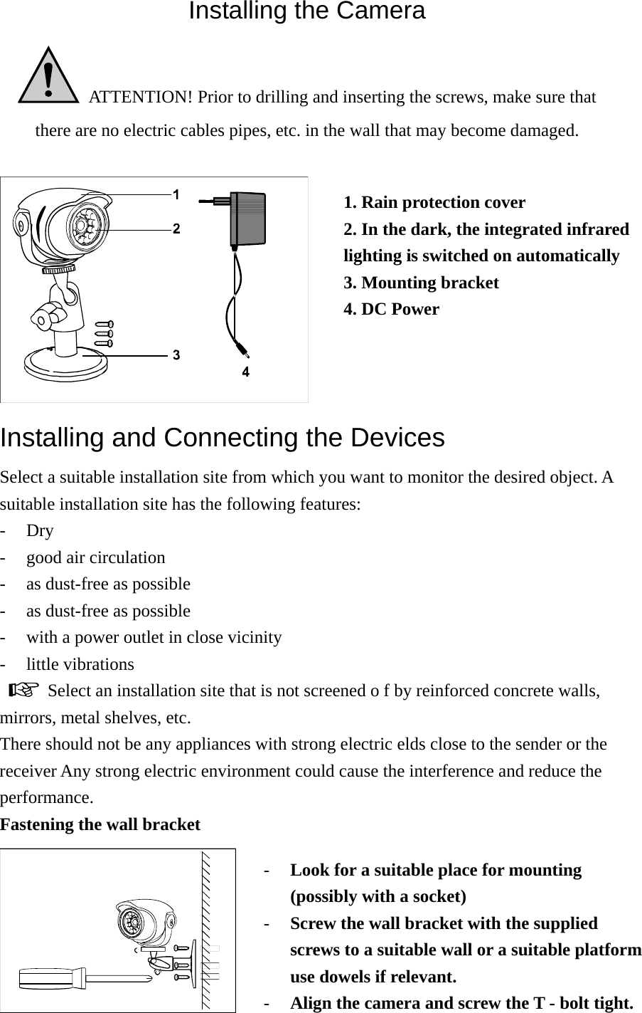
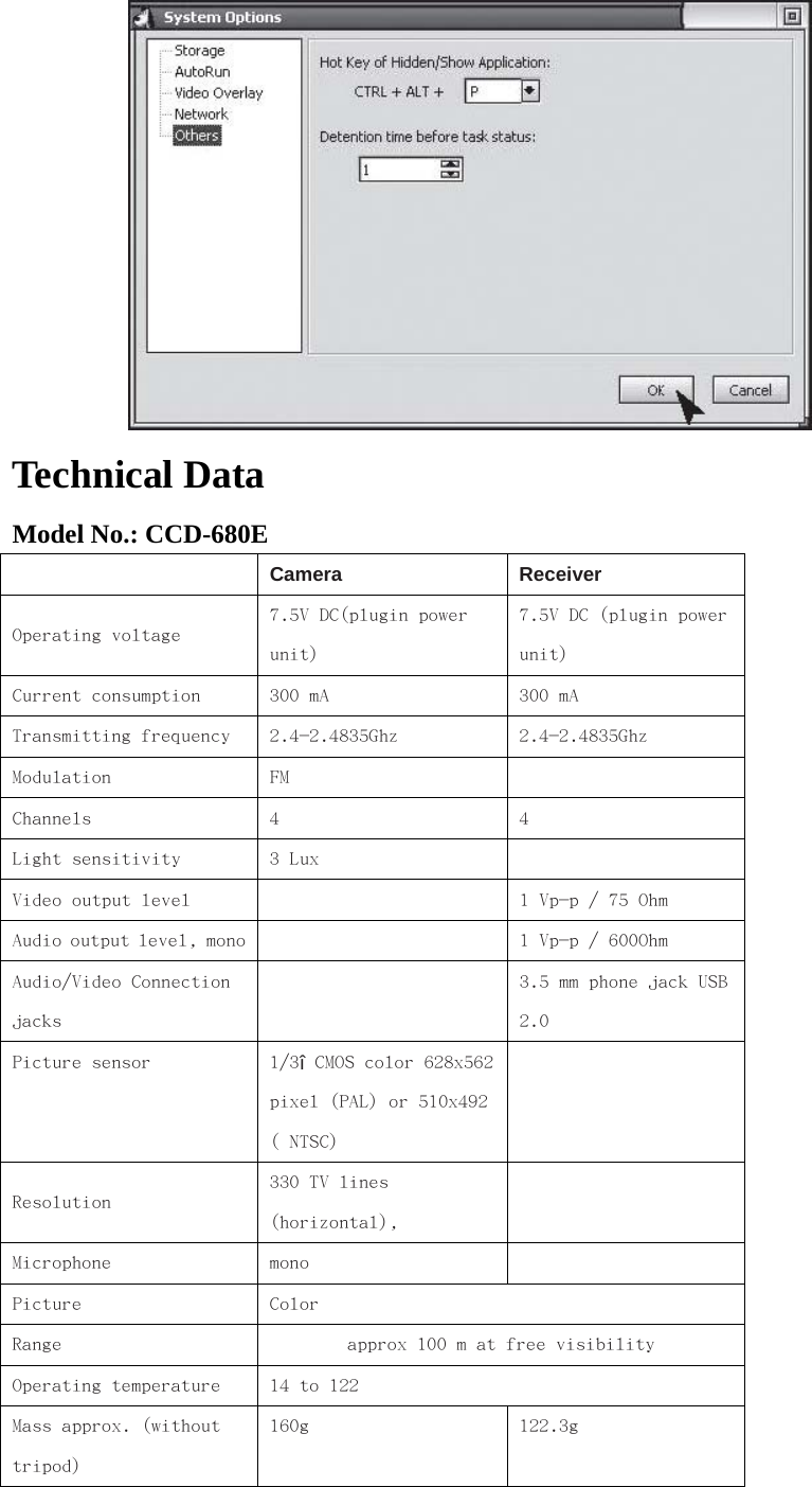
![a) Manual channel selection: To set the channel selection switch on the receiver, please take a pointed object, e.g. a ballpoint pen and select the desired channel switch (no. 1 to no. 4) to position "ON”. The selected channel always remains active. Receiver Set to Receiver Set to Receiver Set to Receiver Set to Channel 1 Channel 2 Channel 3 Channel 4 b) Auto-scan mode: If there is more than one camera in operation, you can allow the channels to run through automatically (scan mode). For this just simply select desired channel on each camera, and adjust the channels to on position on receive accordingly. On monitor you will see the channel change accordingly at an interval of 5 seconds. If not all four channels are occupied with cameras, you have the possibility to block channels which are not occupied (position "OFF") on both camera and receiver. These will simply be left out in the auto-scan mode. -The aerial of the radio camera can be adjusted to ensure the best possible transmission quality. Please rotate them carefully so that they are vertical. The aerial can only be rotated within a certain range. Do not rotate the aerials over and beyond the rotation limits with force as they could be destroyed. -Alter the channel set on the radio camera and on the receiver (channel selection switches and if transmission is disturbed,) See also "Elimination of disturbances". -To switch off the devices, proceed in the opposite order to switching them off. Always pull the plug-in power units out of the mains socket if not used for a longer period. Software installation: CamGard Security System (Home Edition) 1. Double click on CamGuard installation program. 2. Select the language you wish to install, and press [Ok].](https://usermanual.wiki/JSW-Pacific/CCD-602S/User-Guide-764463-Page-9.png)
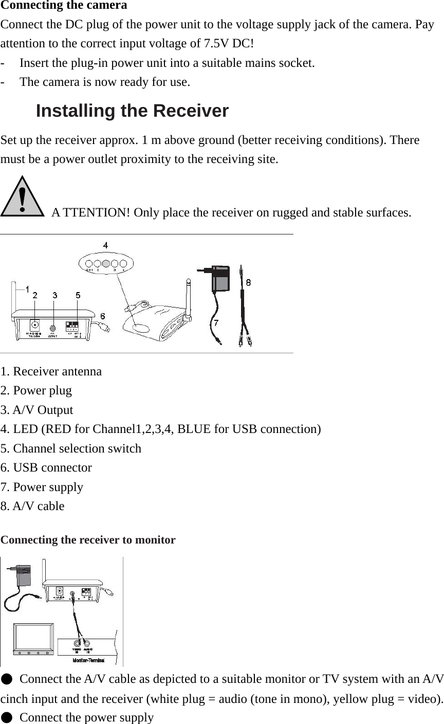
![4. Click [Next] to proceed the installation for CamGard Security System (Home Edition). 5. Click [Yes] to proceed the installation, when the agreement is accepted. 6. Select the destination location you wish to install the program (ex: C:/, D:/), and click [Next] to install the program. 9. Finally, click [Finish] when the software is fully installed. USB Video Device Driver Setup 1. Click [Next] to install the USB Video Device Driver. USB Audio Device Driver Setup](https://usermanual.wiki/JSW-Pacific/CCD-602S/User-Guide-764463-Page-10.png)
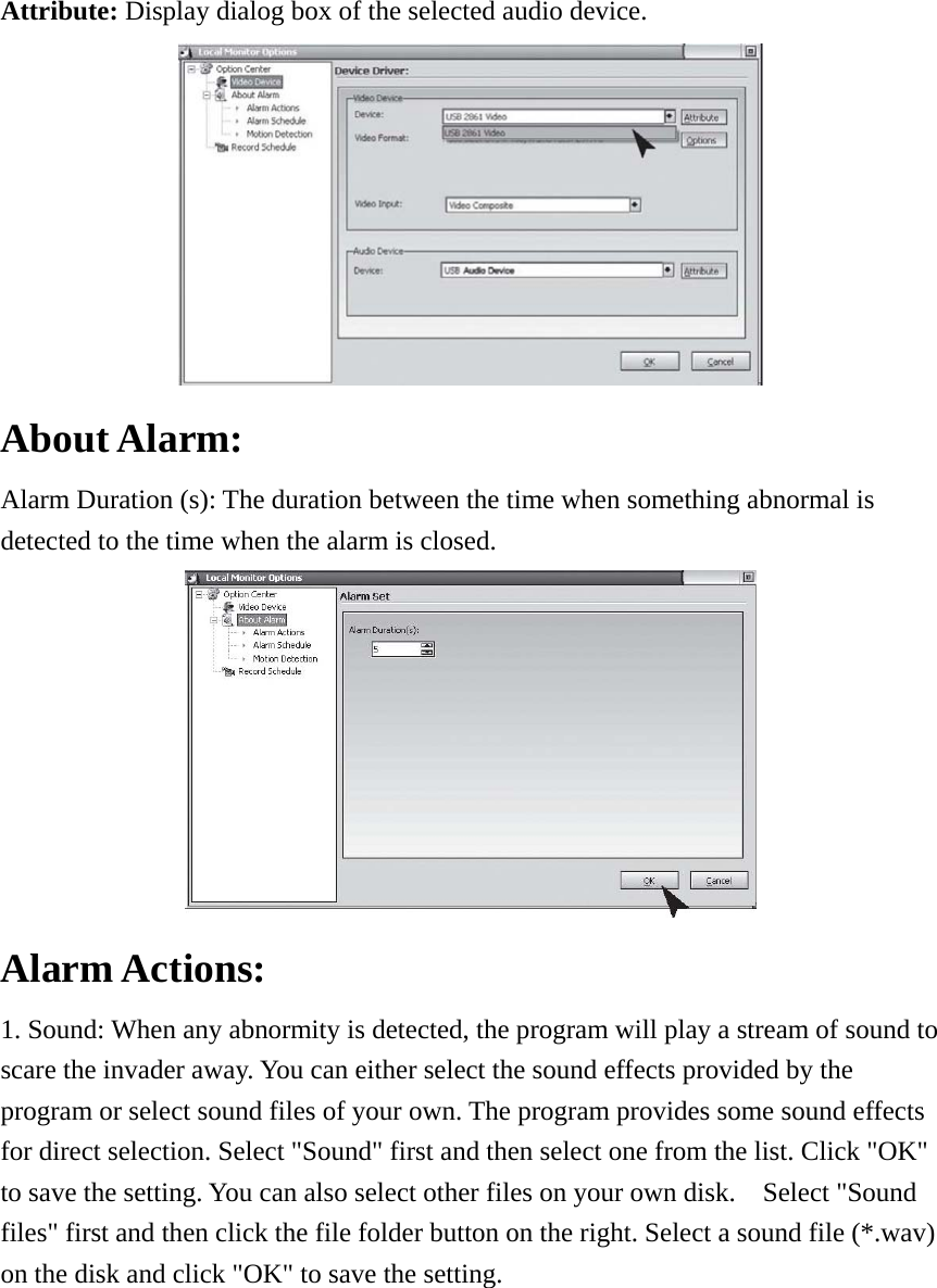
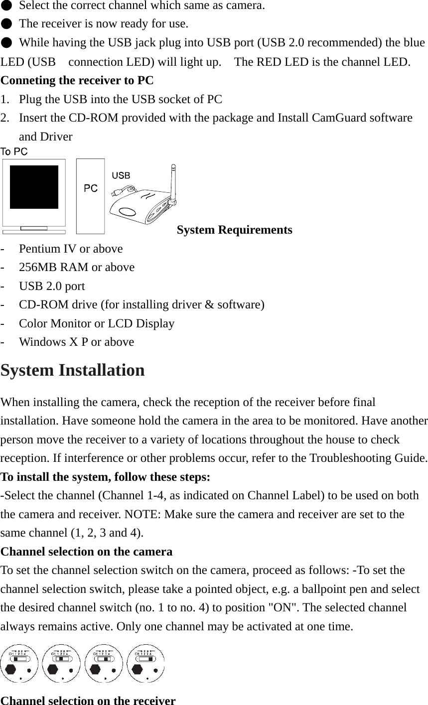
![1. Click [Next] to install the USB Audio Device Driver, and click [Finish] when installation is finished. Device Setting: Select “Device Setting” under “Option”. Device: The video device can be used the listed here in your computer, please choose one for source of video. Attribute: Display dialog box of the selected video device. Options: Display and set size and frame rate of the selected video device. Audio Device Device: The audio device can be used the listed here in your computer, please choose one for source of audio. You can leave it empty.](https://usermanual.wiki/JSW-Pacific/CCD-602S/User-Guide-764463-Page-11.png)