JSW Pacific G95 DIGITAL WIRELESS SURVEILLANCE SYSTEM User Manual
JSW Pacific Corporation DIGITAL WIRELESS SURVEILLANCE SYSTEM
Contents
- 1. User Manual EN
- 2. User Manual FR
User Manual EN
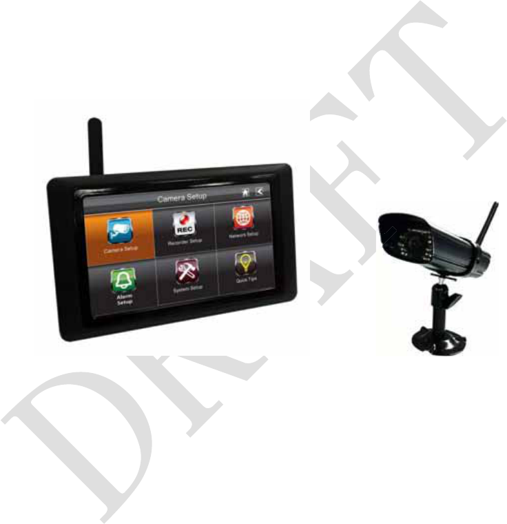
DWH SERIES
VIDEO SECURITY SYSTEM
Installation and Operation Instruction Manual
Model: G955
Version 1.0 DRAFT
This manual should be retained for future reference

1
CONTENTS
IMPORTANT NOTICE.......................................................................................................3
PLEASE READ BEFORE YOU START...............................................................3
WIRELESS DEVICES OPERATING RANGE....................................................3
IMPORTANT SAFETY PRECAUTIONS .............................................................3
REQUIREMENTS FOR REMOTE VIEW................................................................5
KIT CONTENT ...................................................................................................................6
SAFETY AND INSTALLATION TIPS..............................................................................7
Camera Installation.....................................................................................................8
Setting the Camera Channel (optional) ......................................................................9
Pairing the Camera to Receiver (optional) .................................................................9
QUICK START GUIDE....................................................................................................10
Set Up the Camera....................................................................................................10
Set up the Wireless Touch Screen Monitor ..............................................................10
System Operation .....................................................................................................11
Remote Access .........................................................................................................11
SYSTEM INTRODUCTION.............................................................................................13
Live Screen Displays................................................................................................15
Zoom Feature ...........................................................................................................15
Recording Live Video ..............................................................................................15
Playing Back Recorded Video..................................................................................16
SYSTEM MENU ...............................................................................................................17
SYSTEM OPERATION ....................................................................................................18
Camera Setup Screen................................................................................................18
Camera Pairing.........................................................................................................18
Camera Activation....................................................................................................19
Brightness.................................................................................................................19
Recorder Setup Screen .............................................................................................20
Motion Detection......................................................................................................20
Email Alert ...............................................................................................................20
Schedule Record.......................................................................................................22
Clear a Scheduled Recording ...................................................................................23
Network Setup Screen ..............................................................................................23
Internet Setup ...........................................................................................................24
Security Code ...........................................................................................................24
Network Information................................................................................................25
Alarm Setup Screen..................................................................................................26
Period .......................................................................................................................26
Melody .....................................................................................................................27
System Setup Screen ................................................................................................27
Power Saving............................................................................................................27
Screen Auto Lock.....................................................................................................28

2
Time .........................................................................................................................29
Clock Alarm .............................................................................................................29
Time Setting .............................................................................................................30
Timer ........................................................................................................................30
Storage Management................................................................................................31
Format ......................................................................................................................31
Overwrite..................................................................................................................32
System Upgrade .......................................................................................................32
Language ..................................................................................................................33
Quick Tips ................................................................................................................33
REMOTE ACCESS ...........................................................................................................34
Overview ..................................................................................................................34
Downloading Android APP......................................................................................34
Downloading iPhone APP........................................................................................34
Connecting to the Internet ........................................................................................34
MAINTAINING YOUR SYSTEM ...................................................................................36
TROUBLE SHOOTING....................................................................................................37
PRODUCT SPECIFICATION ..........................................................................................38
Recording Time for Memory Card (32GB max) ......................................................38
3
IMPORTANT NOTICE
PLEASE READ BEFORE YOU START
Always use discretion when installing CCTV equipment, especially when there is
perceived policy. Enquire relevant local regulations applicable to the lawful installation
of video recording/surveillance. Third party consent may be required.
WIRELESS DEVICES OPERATING RANGE
Ensure the signal reception viewed from the wireless camera(s) is the best possible
reception between the camera(s) and receiver. If necessary, reduce the distance between
the camera(s) and receiver to improve overall system performance. Wireless Color
Camera Recordable CCTV Kit operating on a secure digital 2.4GHz frequency which
could greatly reduce interference from product such as wireless routers, cordless phones
or microwave ovens.
IMPORTANT SAFETY PRECAUTIONS
Damages caused by non-compliance with this operating manual will void the warranty!
We will not assume any liability for damages to items or persons caused by improper
handling or non-compliance with the safety notices! Any warranty claim will be null and
void in such cases.
1. Do not drop, puncture or disassemble the camera; otherwise the warranty will be
voided.
2. Avoid all contact with water, and dry hands before using.
3. Never tug on the power cords. Use the plug to unplug it from the wall outlet.
4. Do not expose the camera to high temperature or leave it in direct sunlight. Doing so
may damage the camera or cause camera temporary malfunction.
5. Use the devices with care. Avoid pressing hard on the camera body.
6. For your own safety, avoid using the camera or power off the camera when there is a
storm or lightning.
7. Remove the power adapter during long periods between usages.
8. Use only the accessories and power adapters supplied by the manufacturer.
9. To meet the regulations pertaining to parental responsibility, keep the devices out of
the reach of infants.
10. Check power cables, do not get crushed or damaged by sharp edges whenever the
devices are in operation.

4
FCC Compliance Statement: This
device complies with Part 15 of the
FCC rules. Operation is subjected
to the following two conditions:
(1) this device may not cause harmful interference,
and (2) this device must accept any interference
received, including interference that may cause
undesired operation.
Products with CE Marking comply with
EMC Directive (2004/108/EC); Low
Voltage Directive (73/23/EEC);
R&TTE(1999/5/EC); ROHS Directive
(2011/65/EU) issued by the Commission of the
European Community. Compliance with these
directives implies conformity to the following
European Norms:
EMC: EN 301 489
LVD: EN 60950
Radio: EN 300 328
FCC/CE WARNING
This equipment has been tested and found to comply with limits for a Class B digital
device, pursuant to Part 15 of the FCC rules and ETSI(EN) 300328. These limits are
designed to provide reasonable protection against harmful interference in residential
installations. This equipment generates, uses, and can radiate radio frequency energy,
and if not installed and used in accordance with the instructions, may cause harmful
interference to radio communications. However, there is no guarantee that interference
will not occur in a particular installation. If this equipment does interference to radio or
television equipment reception, which can be determined by turning the equipment off
and on, the user is encouraged to try to correct the interference by one or more of the
following measures:
-Reorient or relocate the receiving antenna.
-Move the equipment away from the receiver.
-Plug the equipment into an outlet on a circuit different from that to which the receiver
is connected.
-Consult the dealer or an experienced radio/television technician for additional
suggestions.
You are cautioned that any change or modifications to the equipment not expressly
approved by the party responsible for compliance could void your authority to operate
such equipment.
DISPOSAL
If the camera system no longer functions or can no longer be repaired, it
must be disposed of according to the valid statutory regulations.
Disposal of spent batteries/accumulators:
You are required by law (Battery Ordinance) to return all spent batteries
and accumulators. Disposing of spent batteries/accumulators with common household
waste is prohibited! Batteries/accumulators that contain hazardous substances are
marked with the symbols on the side. These symbols indicate that it is prohibited to
dispose of these batteries/accumulators in the household waste. The abbreviations for
the respective heavy metals are: Cd=cadmium, Hg=mercury, Pb=lead. You can return
spent batteries and accumulators that can no longer be charged to the designated
collection points in your community, outlets or wherever batteries or accumulators are
sold. Following these instructions will allow you to fulfill the legal requirements and
contribute to the protection of our environment!

5
zSystem “Device ID” and “Password” are provided on a label applied at
the back of the LCD Monitor (behind the pull out stand).
The “Device ID” and “Password” are needed for remote viewing.
For security purpose, it is recommenced for user to copy the “Device ID”
and “Password” information to the user manual, following by removing the
label containing the “Device ID” and “Password” information.
Please store this manual in a safe place to protect the device ID and
password information for future reference.
zAlways use discretion when installing CCTV surveillance equipment
especially when there is perceived policy. Enquire regarding local
regulations applicable to the lawful installation of video
recording/surveillance. Third party consent may be required.
REQUIREMENTS FOR REMOTE VIEW
Supported Device
- iPhone / iPad / iPod Touch w/ iOS 5.0.1 or above
- Android smartphone / tablet v2.3X or above"
Note: Not suitable for Windows7 or Blackberry Smartphones
Recommended minimum internet upload speed
512Kbps upload speed (or bandwidth) to achieve up to an average of 2FPS viewing speed.
Average viewing speed will depend on other restrictions by your ISP (internet service
provider).
6
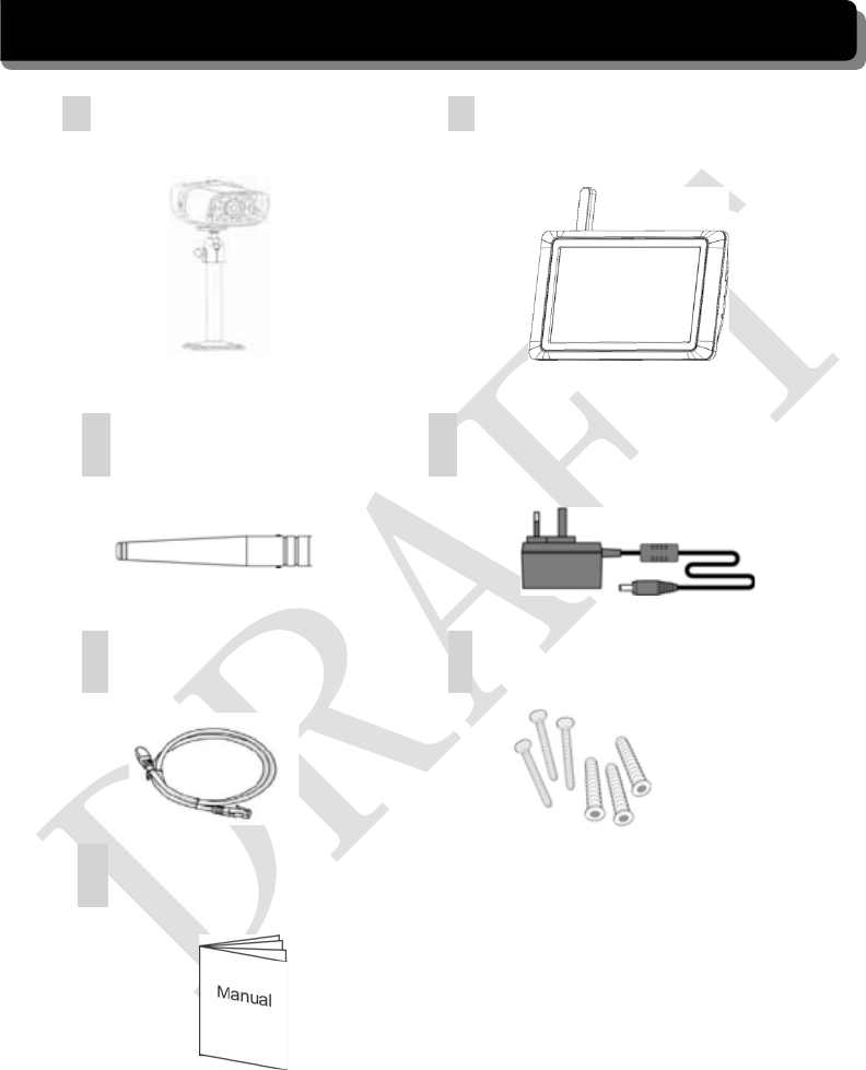
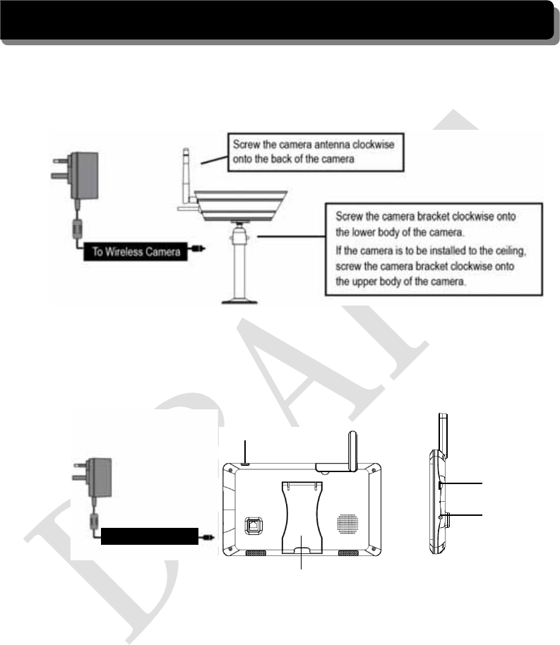
KIT CONTENT
AWireless Camera w/ stand
x 1
BWireless Touch Screen LCD
Monitor x 1
C Camera Antenna x 1 D5V/1A Power Adapter x2
EInternet Cable x 1 FScrew Bag x 1
GInstruction Manual x 1 Tools Required:
yElectric drill
y5mm masonry drill bit
y15mm masonry drill bit
yNo. 2 Philips screwdriver
7
SAFETY AND INSTALLATION TIPS
LCD Touch Screen Monitor
zkeep away from heat sources and high temperature places
zAvoid direct sunlight
zAvoid humid places
zAvoid vibration
zInstall in a ventilated environment
zThe supplied SD card can be replaced with up to a 32GB SD card if required
Installation Notes
Always follow manufacturer’s advice when using power tools, steps, ladders, etc and
wear protective equipment (e.g, safety goggles and gloves) when drilling holes, etc.
When using ladders ensure they are positioned on a firm stable surface at an angle and
suitably secured. Check for hidden electricity wires or water pipes before drilling any
holes. If in doubt use a cable/pipe locator. It is recommended to avoid exposing the
camera to extreme weather conditions (e.g, under a gutter which is prone to water leaks).
After drilling any holes through an external wall for a cable, ensure the hole is sealed up
using a suitable sealant to prevent drafts.
To prevent a fire or electrical shock hazard, do not attempt to open the housing while the
camera is exposed to rain water or wet conditions. Do not expose any wiring connections
to weathering. If terminating any wiring connections outdoors then use a suitable
weathering box to insulate the connections.
There are no user serviceable parts inside. Refer servicing to qualified service personnel.
NOTE: The camera has an open field RF operating range of up to 150m.
8
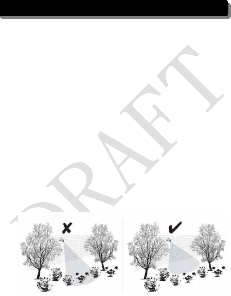
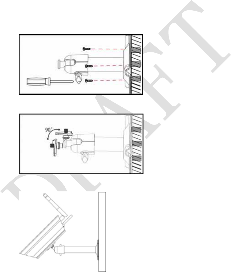
Camera Installation
zAvoid positioning the camera so that it is facing directly at the sun as this will impair
the picture quality viewed.
zAvoid pointing the camera lens directly through clear glass as the night vision LEDs
will cause a blurred image at night.
zAvoid pointing the camera directly at any bushes, tree branches or moving objects that
might naturally move due to winds. This is also because if you need to use the motion
detection feature in the PC software to record movement the software might record
unnecessarily.
Secure camera stand on the stable
surface
Loosen up the Thumb screw
Adjust proper view angle then secure the joint
with T-bolt.
9
Setting the Camera Channel (optional)
The wireless camera is supplied preset to channel 1.
The monitor supports up to 4 cameras. Follow the steps below in Camera Setup section to
setup or change the monitor channel of the camera. If you are adding another camera to
link with the supplied monitor in this kit, then ensure its channel is set to a different
channel to the existing camera(s).
Pairing the Camera to Receiver (optional)
Follow the steps in Camera Setup section to setup or change the channel of the camera. If
you are adding another camera to link with the supplied monitor in this kit, then ensure its
channel is set to a different channel to the existing camera(s).
Note:
If the camera is located within 1m to 1.5m from the monitor and the camera's volume on
the receiver is turned on, then you may hear a whistling noise on the monitor which is the
feedback picked up by the microphone. In this case please locate the camera further away
from the monitor to prevent this noise.
If the power connection to the camera is kept outdoors, ensure the connection is suitably
protected.
10
QUICK START GUIDE
For further details on the installation of the camera bracket and fixings, please refer to the
Camera Installation section.
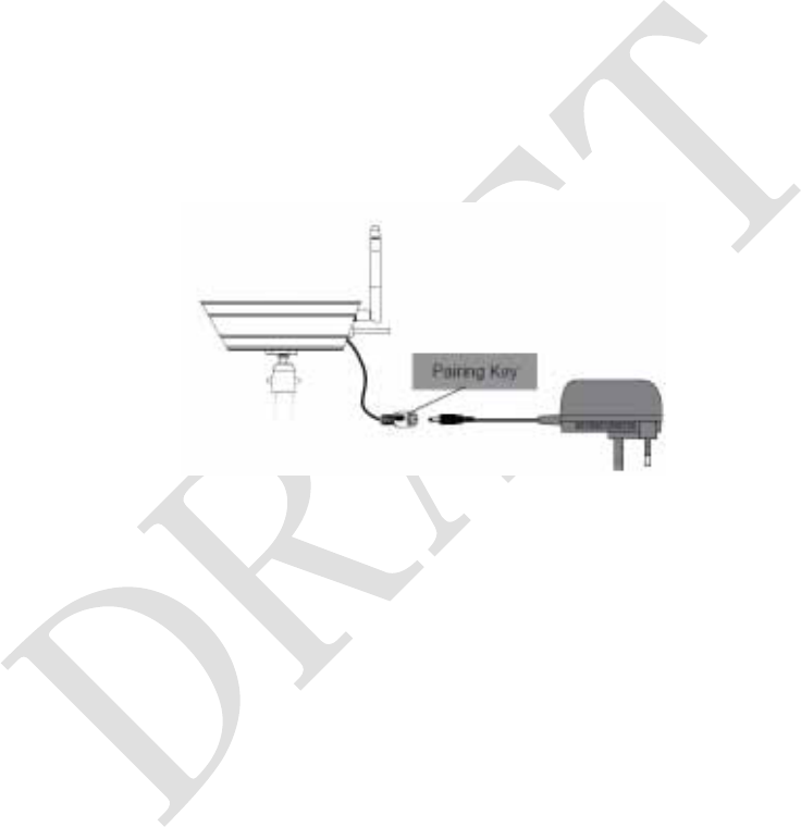
Set Up the Camera
Set up the Wireless Touch Screen Monitor
1. Flip out the stand, extend the antenna, connect AC/DC adapter to the input on the
side of the monitor.
2. Press and hold the POWER button on the top of the monitor for 3 – 4 seconds to
power it up.
3. The receiver displays Welcome Screen for a few seconds and then transitions to the
LIVE view.
4. Place the SD card into the SD card slot located on the side of the monitor.
Note: The screen remains dark until the camera is powered up.
To Wireless Camera
To Touch Screen Monitor
P
ower
A
ntenna
P
u
ll
-
O
ut
S
tan
d
SD
s
l
ot
AC
P
ower
Connection

11
The monitor is fitted with a rechargeable battery and can operate for up to 2 hours on
battery power once fully charged (w/Power Saving function activated). The monitor can
be carried around anywhere within operating range of the camera(s), but should be used in
a dry environment as it is not weatherproof.
System Operation
Please refer to the System Operation section for Camera, System and Recording Settings.
Remote Access
Can be done via iPhone / iPad / iPod Touch w/iOS 5.0.1 or above, Android smartphone /
tablet v2.3X or above connected to 3G/WiFi internet.
For an Android device
Please refer to the Downloading Android APP section.
For iPhone, iPad1, iPad2, New iPad
Please refer to the Downloading iPhone APP section.
12
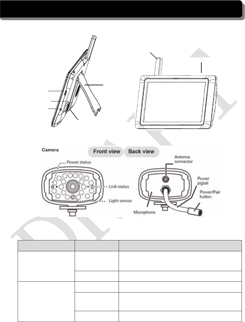
GETTING TO KNOW THE MONITOR AND CAMERA
WHAT THE LIGHTS MEAN
Light State What it means
Power status
On
(Red) The camera is on.
Off The camera is off.
Link status
Flashing The camera is in pairing mode.
On
(Green) The camera is connected to the receiver.
Off The camera is in standby.
Power
On/Of
SD slot
AC Power
Connection
Antenna
Data Cable Connection
Pull-Out
Stand
Receiver
(back/side)
Receiver
(Front view)
Reset Button
13
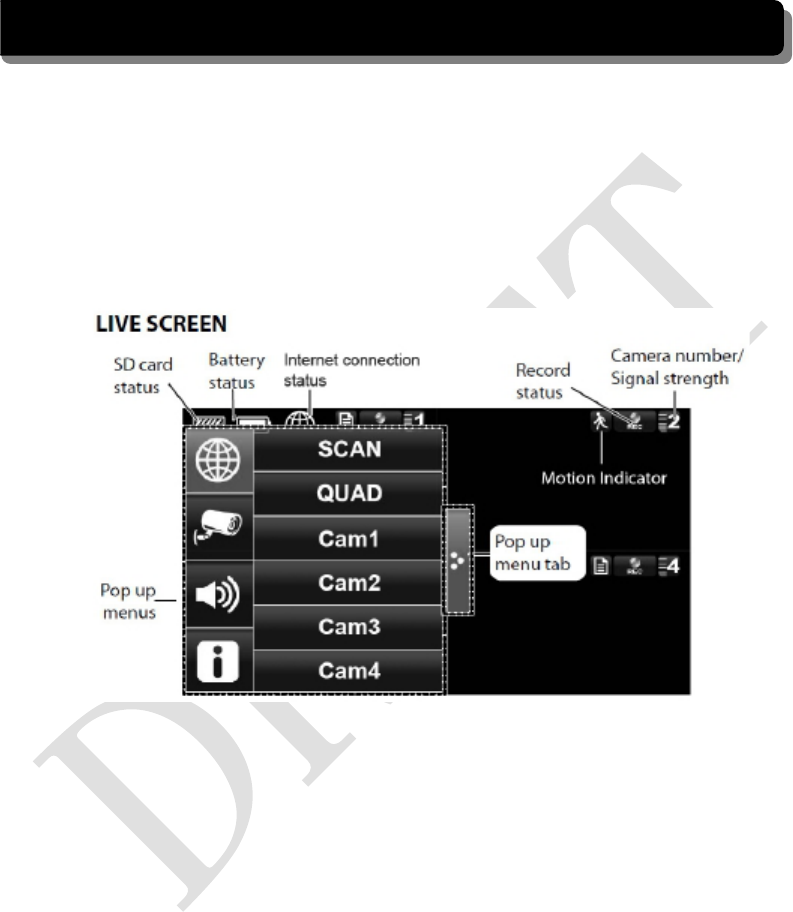
SYSTEM INTRODUCTION
Your monitor’s system software operates through a series of screens that let you choose
groups of operations. For example, when you tap on the camera icon in the Pop-up menu,
you can set how you want the main viewing screen, “the Live screen” to display images
from the paired cameras. You can scan between cameras, show all cameras on a single
screen (Quad view), or only display specific camera.
The Live screen lets you view the camera transmissions. It also lets you set up your screen
display and make adjustments to it. Icons on the screen itself let you monitor power and
camera status.
14
ICON WHAT THE ICON MEANS
Camera Mode
Select how you want the Live screen to display camera input:
Scan between cameras (5 seconds)
Quad view (all paired cameras display)
Full view (1 camera displays on full screen)
Volume
Adjust the volume level.
System Settings
Access the system software operation and setting page or view recorded
events.
SD Capacity Indicates memory capacity remaining.
Battery Capacity Displays battery capacity. This graphic shows battery at nearly full.
Camera Number Displays the camera number and signal strength through the status lines
to the left of the number.
Record Status Tap to start or stop recording for that camera
• Steady on - Not recording • Flashing - Recording
Connecting to the
Internet Connecting your system to the internet.
Internet Connected Connects your system to the internet.
Intranet Connected Connects your system to the intranet.
Remote View Indicates remote viewing is in process.
Motion System indicates motion detection recording in progress.
Scheduled System indicates scheduled recording in progress.
Pop Up Menu Tab Opens and closes the pop up menu display.
No SD Card
Indicator Displays red when the SD card is not present or is damaged.
Zoom Zoom in / out of a particular section of the live video
15
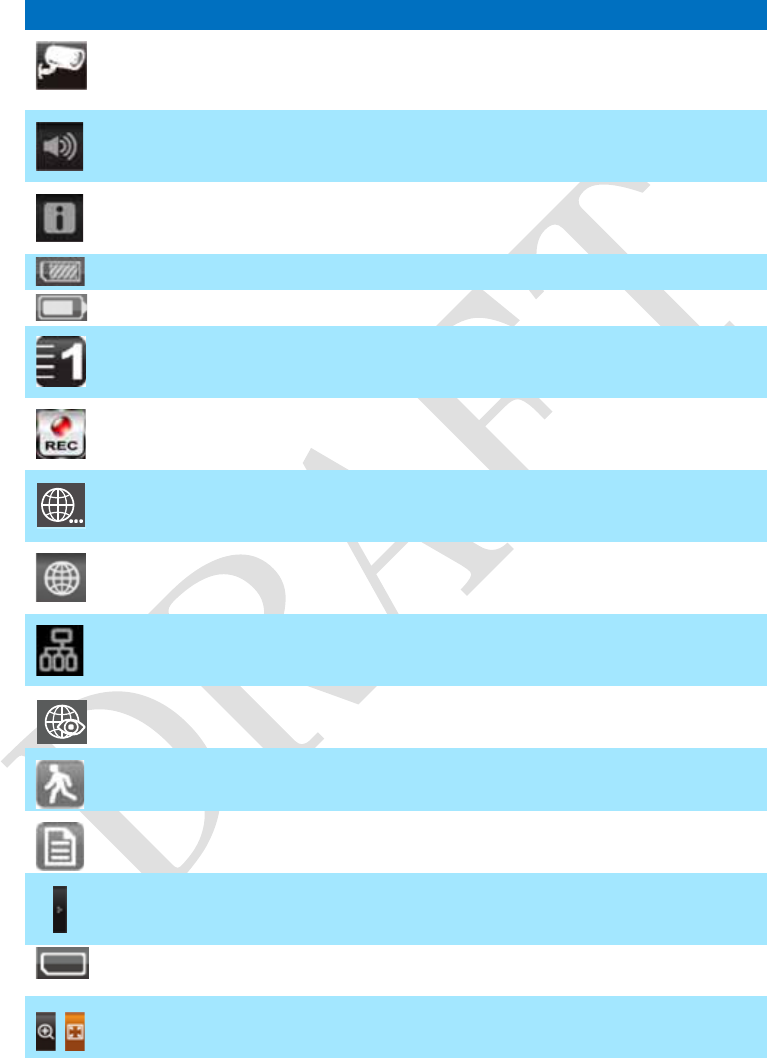
Live Screen Displays
The Live screen displays in 2 views - Quad View or Full View. Quad View displays the
images in 4 quadrants (only display camera that is ON). Tap a quadrant to display single
camera view / full view. Tap on that image again to return to Quad View.
Zoom Feature
To zoom into a particular area,
1. Go to full view, then tap to activate zoom mode.
2. Select the zone by tapping the zone area to view zoom in screen.
Recording Live Video
1. On the Live screen, tap for the camera to begin recording.
2. Tap it again to stop recording.
You can record all cameras at the same time. With manual recording, each recording
session (video clip per camera) is two minutes in length.
16
Playing Back Recorded Video
From the pop-up menu, tap the following
icons
The Record List screen displays:
Î
1. Tap on the highlighted day containing the recording you want to view.
The Record List screen will display that day’s recordings listed in a folder.
If you tap on a day that is not highlighted, a folder displays with no recordings
listed.
2. Tap on the recording you want to view. It displays on the screen.
3. Tap on any area of the screen that does not have control icons to bring up the
playback progress bar. Tap that area again to close it.
4. While playback progress is visible, you can fast forward/rewind by dragging the
playback bar.
5. When playback ends, tap or to return to the Record List.
17
SYSTEM MENU
From the pop-up menu, tap the following
icons
The Main Screen displays:
Î
The SYSTEM MENU highlights the Camera Setup option as the default.
Main Screen Sub Screens What it Does
Camera Setup Camera Setup Pairs new cameras to the receiver.
Camera on Makes the cameras visible to the monitor.
Brightness Brightens or darkens the video of that camera.
Recorder Setup Motion Detection Records when something moves in front of the
camera. Continues recording for 2 minutes.
Schedule Record Set up a schedule for pre-determined recording
times and lengths.
N
etwork Setup Internet Setup Select the type of internet connection to be
used.
Security Code Set a security code for remote access.
N
etwork Information Displays information about your network and
the receiver’s unique DID number.
Alarm Setup Period Set a length of time for the alarm to sound.
Melody Select a melody to play for the alarm.
System Setup Power Saving Temporarily turns off the LCD after the
system is idle for 2 minutes to conserve
p
ower.
Screen Auto Lock Locks the screen from further activity until the
screen is unlocked.
Time Set the time in 12-hour increments.
Format Storage Formats / erases all the data on the SD card.
System Upgrade Upgrades the receiver firmware.
Default Lists the original system defaults.
Quick Tips
N
/A Provides a list of 10 common questions.
18
SYSTEM OPERATION
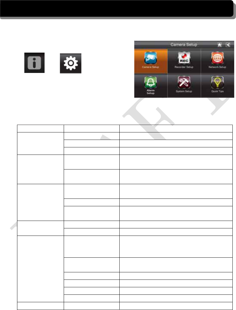
Camera Setup Screen
Tap on camera setup.
This screen should display:
Camera Pairing
Your camera is paired to the monitor at the factory to channel 1.
To add new camera(s) to your system, you have to pair it to the different channel(s).
From the pop-up menu, tap the following
icons
The Main Screen displays:
ÎÎÎ
1. Tap the camera image you want to pair. A processing icon displays for a 60 second
countdown.
2. Press and release the Pairing button on that camera’s power cord (please refer to the
Getting to Know the Monitor and Camera section). The system will indicate pairing is
successful when pairing completes.
3. The system will automatically adjust the Camera On screen.
19
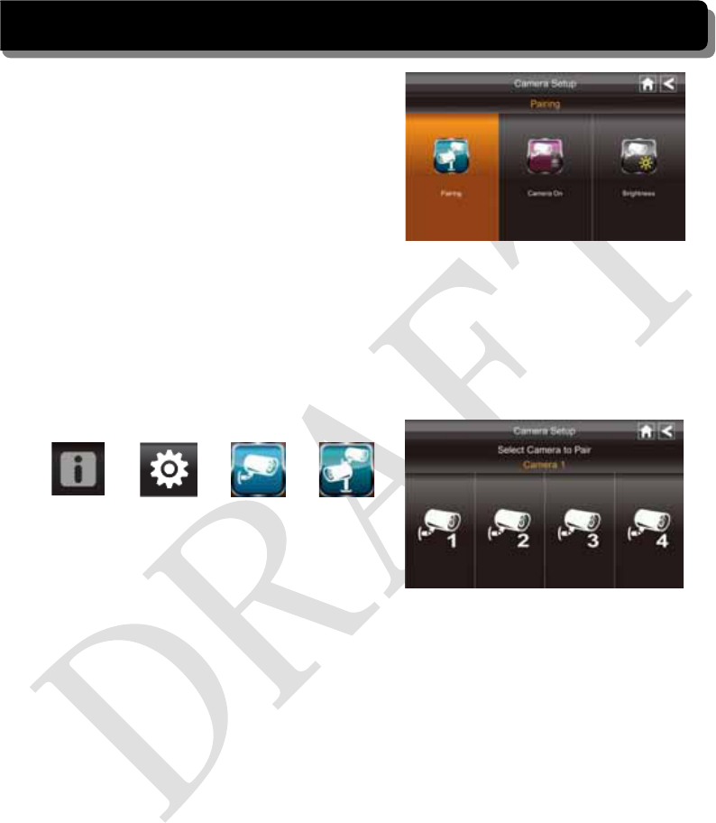
Camera Activation
When you add a camera to your system, the system will turn on the camera automatically.
From the pop-up menu, tap the following
icons
The screen displays:
ÎÎÎ
An Xindicates a camera is OFF, a check indicates ON. Tap on the camera to turn it ON or
OFF.
Brightness
From the pop-up menu, tap the following
icons
The screen displays:
ÎÎÎ
Tap the camera to change brightness level. The default brightness is 0, and the range is
from -2 through 2.
20
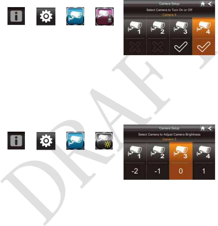
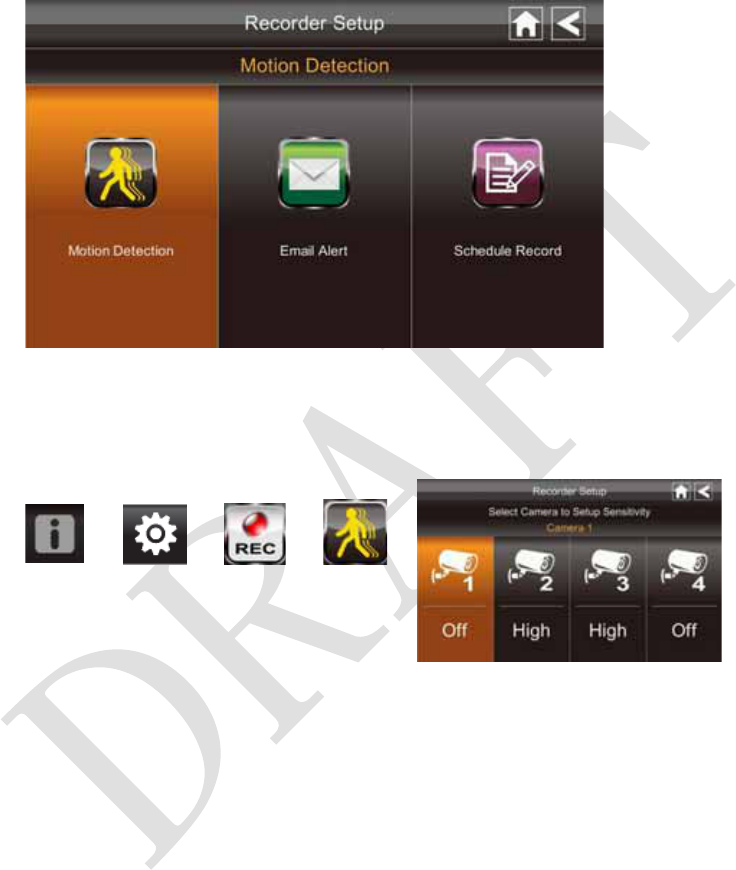
Recorder Setup Screen
Motion Detection
From the pop-up menu, tap the following
icons
The screen displays:
ÎÎÎ
Tap the camera’s to set the sensitivity to Off, Low or High.
Default = low. The screen will return to the Motion Detection screen after 10 seconds or
when you press the Back icon.
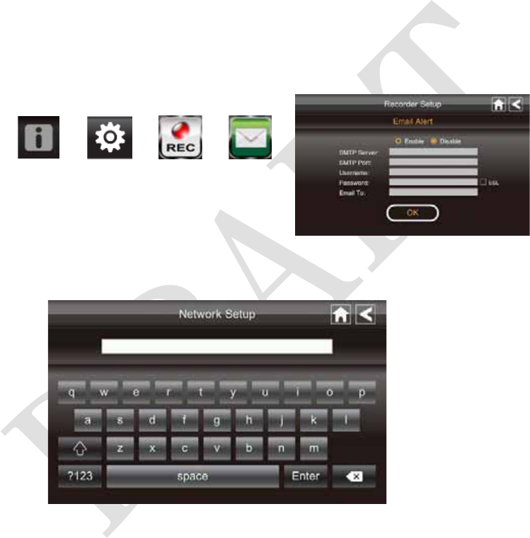
Email Alert
The system can notify you when it detects motion from any camera by sending you an
email alert. The email alert contains information such as the time that motion was detected
and by which camera. In order to enable the Email Alert function, you must enter both
incoming and outgoing email addresses.
We strongly recommend you use Gmail to set up as the outgoing email server.
The outgoing email server (SMTP server) is responsible for sending out the email
notification to tell users when the system detects motion from any camera (Motion
Detection must be activated).
21
The incoming mail server (Email To) receives the email notification sent from the SMTP
server, The user must be able to receive email on a Windows PC or on mobile devices
(such as an iPhone, iPad or Android smartphone or tablet) to receive e-mail alerts from the
system.
When you receive an email alert, you can view live video from iPhone, iPad, Android
smartphone or Android tablet through apps. Free apps are available through the iTunes
App store or the Android Market.
From the pop-up menu, tap the following
icons as they appear on the screens:
The screen displays:
ÎÎÎ
1. Tap Enable to activate Email Alert or Disable to deactivate it.
2. Tap on the SMTP Server field. A keyboard screen displays.
3. Enter your outgoing e-mail SMTP server (example: johndoe@gmail.com). You can
switch the keyboard from alphabetical characters to numbers/symbols and back again
by tapping the field to the left of the space bar. Tap Return. The Email Alert screen
displays again.
4. Repeat the previous step for the Password field. Tap Return. The password entered
here must be the same password as the password for the outgoing email account.
5. Repeat Step 3 for the Email To field. Only one incoming email account will be
22
accepted by the system. The incoming email account can be different from the
outgoing email account.
6. Tap OK to save the settings, then tap to return to the previous screen.
If you are using Gmail as the outgoing SMTP server, check SSL and use the data in
the following table:
For Gmail
SMTP Server Smtp.gmail.com Enter this.
SMTP Port 465 Enter this.
Username XXXX@gmail.com Enter your gmail address in full,
including @gmail.com.
Password XXXXXXXXXX Enter the password for this
gmail account.
Email to XXXX@gmail.com Enter the email address where you
want the alerts sent.
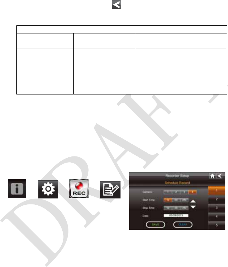
Schedule Record
Up to 5 scheduled recording sessions available in a single day. You are limited to the size
of the SD card for how long a total recording time you have. These recording sessions
must begin and end within a single 24-hour period. They cannot cross into the next day.
From the pop-up menu, tap the following
icons
The Schedule Record screen displays:
ÎÎÎ
1. Tap the camera/channel number you want to record (1 - 4). Multiple cameras can be
selected.
2. Set the recording start and end time. Tap the hour and minutes boxes separately and
use the UP and DOWN arrows to scroll through the times.
3. Tap the AM/PM block to toggle between them.
4. Tap on the blank DATE box. The Schedule Record Calendar screen displays.
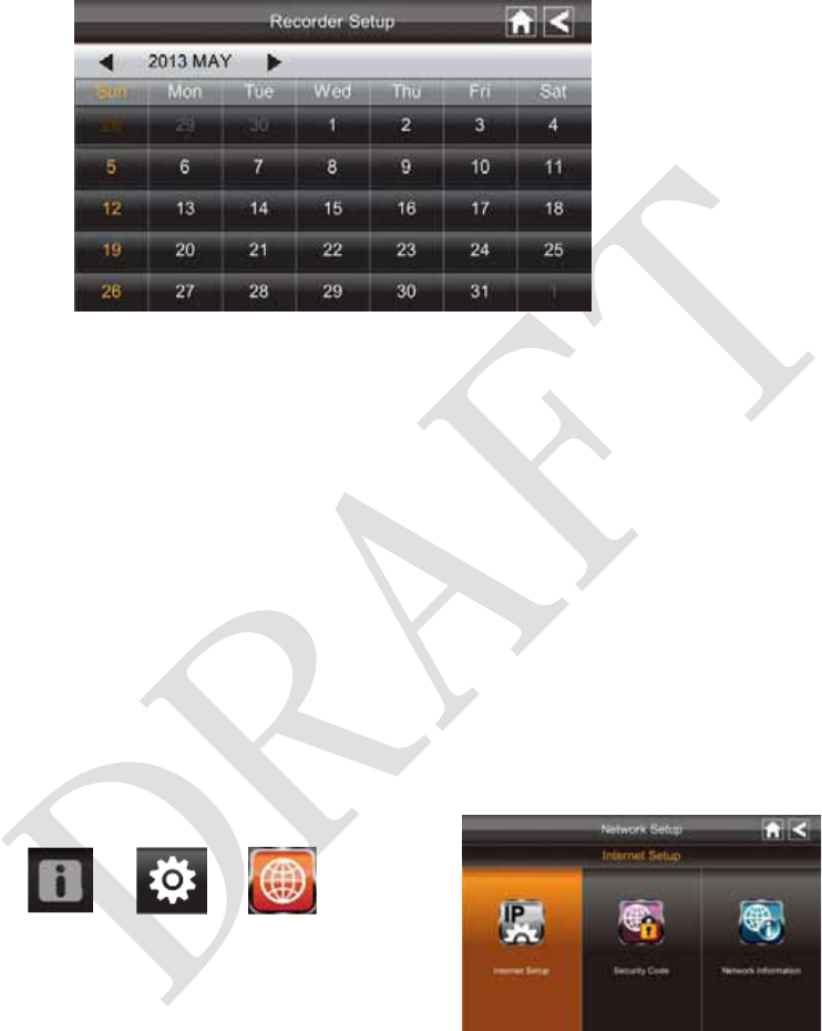
23
5. Tap on the date you want the recording. The previous screen displays.
6. Set up the recording and then tap Save. You can select another recording session to
schedule.
Clear a Scheduled Recording
1. Access the Schedule Record screen.
2. Tap on the scheduled recording you want to clear (1-5). The screen displays the
settings for that schedule.
3. Tap CLEAR. The screen resets to the default values for that recording slot.
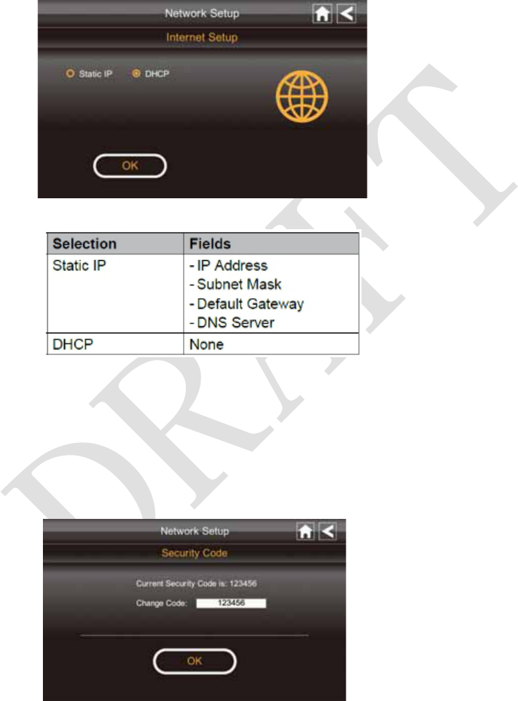
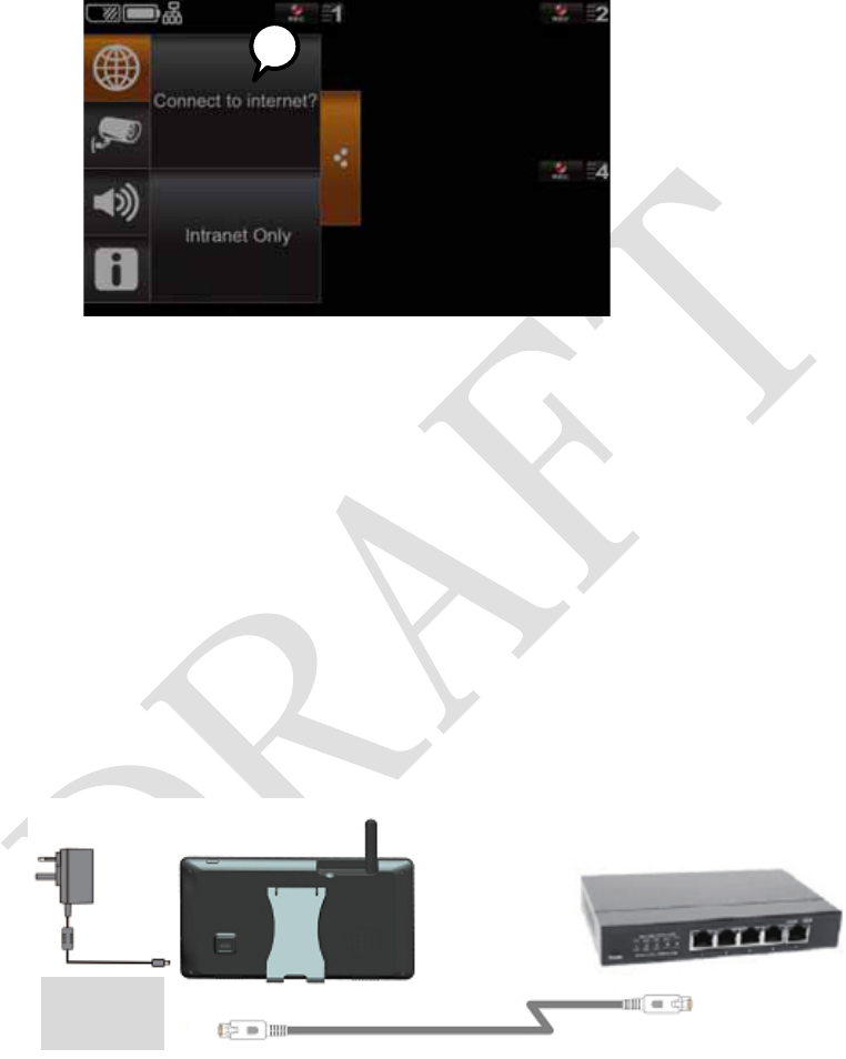
Network Setup Screen
The Network Setup screen allows you to select your internet type, set a security code. You
can also display system default configuration.
From the pop-up menu, tap the following
icons
The Network Setup screen displays:
ÎÎ
24
Internet Setup
1. Tap Internet Setup icon to display the Internet Setup screen.
2. Tap on your selection and fill in the fields requested. Tap OK.
3. Tap OK at the system reboot prompt. The Network Setup screen displays.
Security Code
Set up your security code to limit who can have access to the system from a remote
location.
1. Tap Security Code icon to display the Security Code screen.
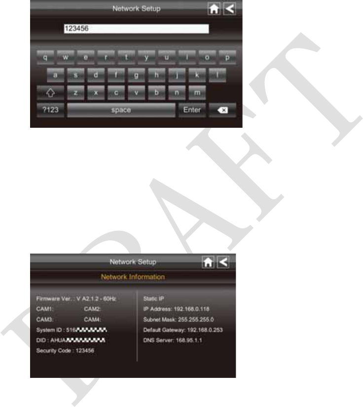
25
2. If you have previously entered a code, the screen will display your current code
3. Tap on the change code field, a key board screen displays.
4. Enter your security code.
5. Tap OK. The system will return to Network Setup screen.
Note: Security code must be entered to gain remote access. To protect your privacy,
please be sure to change the default password 123456 into your personal security code.
Network Information
1. Tap the Network Information icon to display the Network Information screen.
2. Tap the BACK arrow to return to the previous screen.
Note:
The DID is a unique code specific to your monitor and is required to gain remote access
to your cameras over the internet.
The information in the DHCP setting is assigned to your monitor from your home router.
26
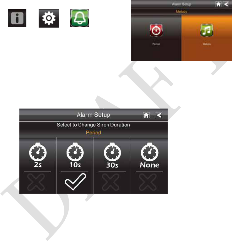
Alarm Setup Screen
From the Alarm Setup screen, you can:
zSet the length of time the alarm sounds
zSelect a melody for the alarm.
ÎÎ
Period
This selection allows you to select the alarm/siren duration for Clock Alarm and Timer.
1. Tap Period. The Set Siren Duration screen displays.
2. Select the alarm duration time required
3. Tap the BACK arrow to return to the previous screen.
27
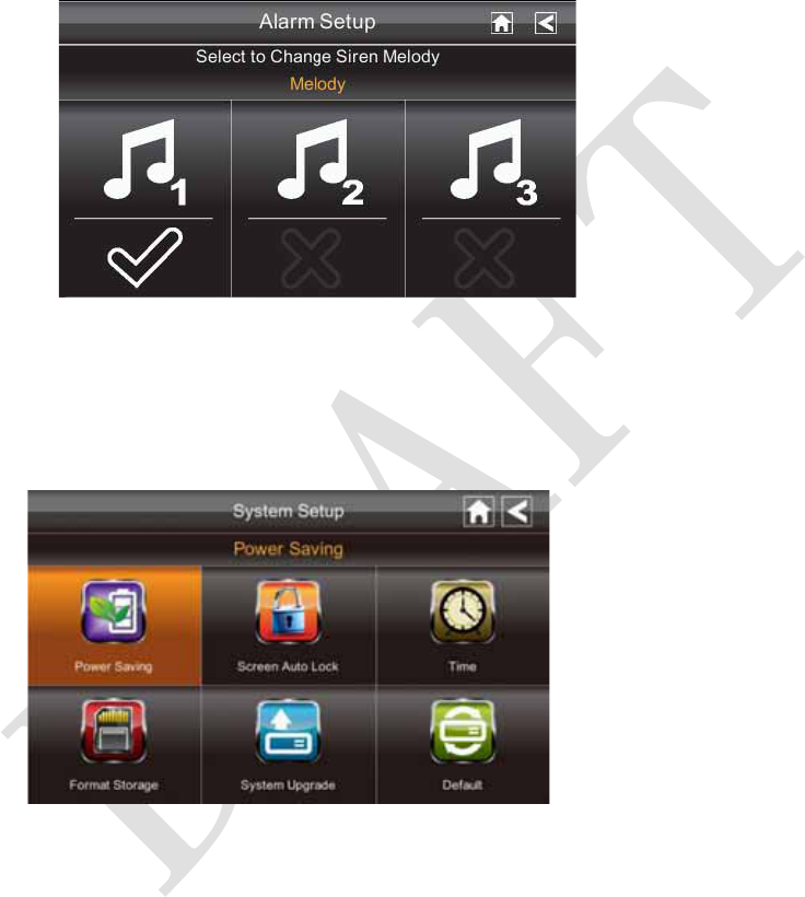
Melody
This selection allows you to select a melody for the siren.
1. Tap Melody. The Change Siren Melody screen displays.
2. Select the melody required
3. Tap the BACK arrow to return to the previous screen.
System Setup Screen
Power Saving
In Power Saving mode, the monitor will shut off LCD after idle for 2 minutes. Press
Power button once to reactivate the monitor.
If a motion detection event or scheduled recording begins, the LCD turns back on
automatically.
28
1. Tap Power Saving Enable to activate power saving. Default is off.
2. A check mark appears on your selection.
3. Tap the BACK arrow to return to the previous screen.
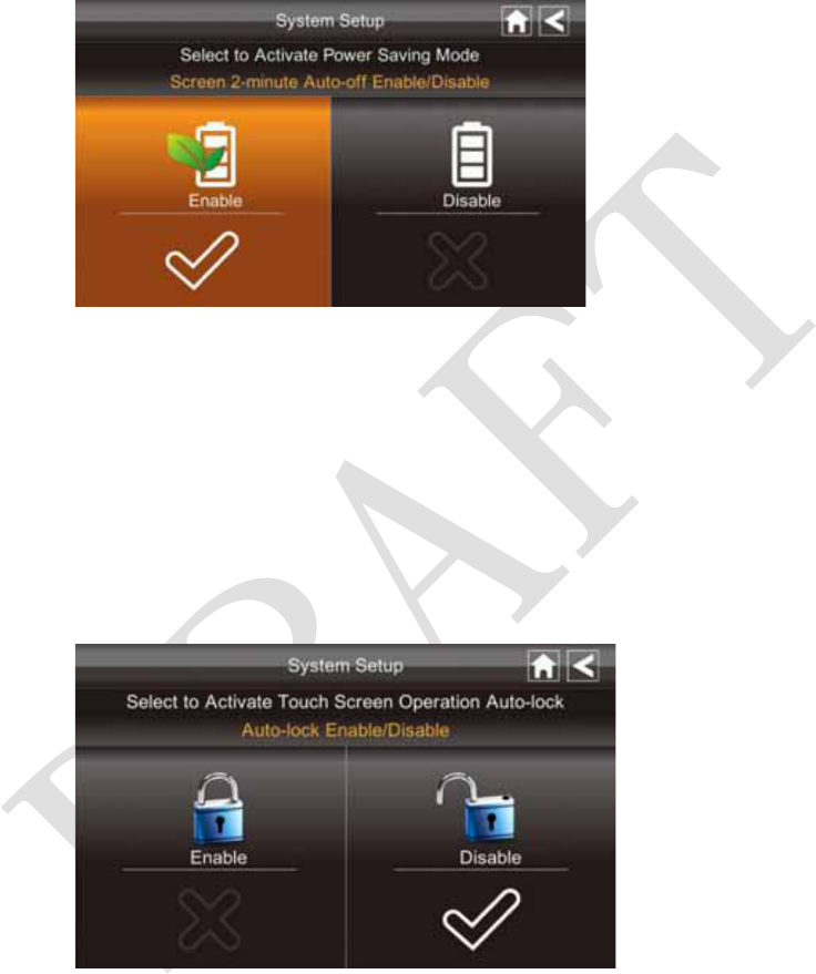
Screen Auto Lock
In Auto Lock mode, the monitor will enter screen lock mode after it has been idle for 2
minutes. Auto Lock disables the touch screen and removed the icons from the display.
1. Tap Screen Auto Lock
2. Tap your selection; a check mark displays.
3. Tap the BACK arrow to return to the previous screen.
Note: From the Live screen, tap the Power button once to unlock the screen and
return to normal touch screen operation.
29
Time
The Time screen lets you set up clock alarms, set the system time, and set a timer.
From the pop-up menu, tap the following
icons
The screen displays:
ÎÎÎ
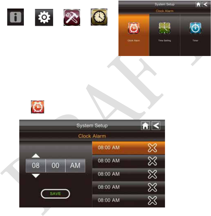
Clock Alarm
This feature operates as an independent alarm clock. It does not affect the operation of
live video or recording video.
1. Tap to display the Clock Alarm screen.
2. Tap on an alarm button (total of 5 to select from).
3. Tap on the hour/minutes block then UP/DOWN arrows to set the time.
4. Tap on AM/PM to toggle between the two.
5. Tap SAVE, then back.
30
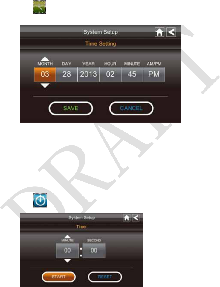
Time Setting
This screen contains fields to set the Month, Day, Year, Hour, Minute and AM/PM.
1. Tap to display the Time Setting screen.
2. Tap on each field to set it. The UP/DOWN arrows shift to that field. Use UP/DOWN
to set the field.
3. Tap on the AM/PM block to switch between the two.
4. Tap SAVE when you are finished.
Timer
This feature operates as an independent alarm clock. It does not affect the operation of
live video of recoding video.
1. Tap to display the Time Setting screen.
31
2. Tap on each field to set it. Use UP/DOWN to set the field.
3. Tap START to begin the time. When the time reaches 00:00, an alarm beeps until you
tap OK.
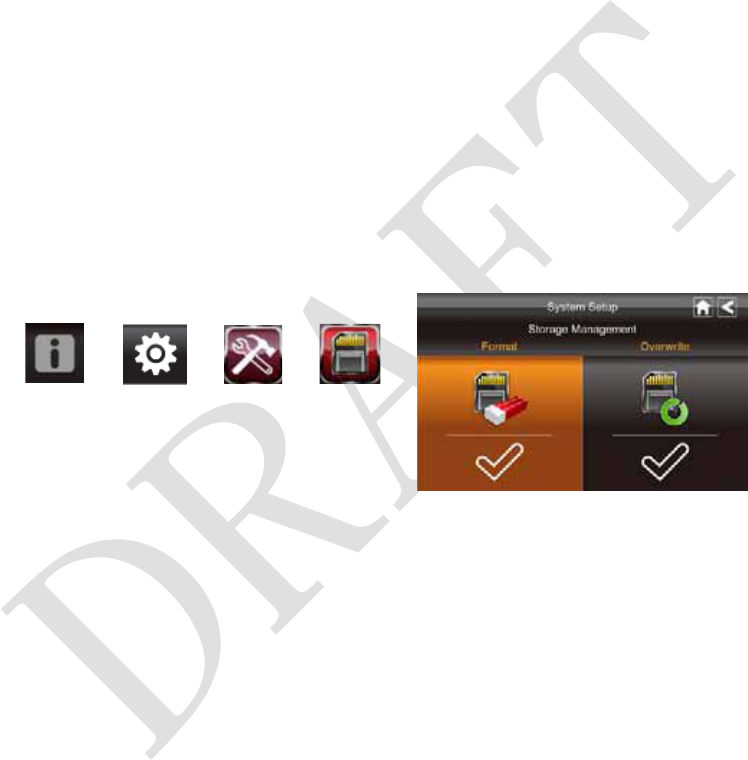
Storage Management
The Storage Management screen lets you format the SD card or set up the SD card
overwrite function.
Format
When using an SD card other than the provided one, it is highly recommended that you
format the card using these procedures. Formatting any SD card deletes all files on that
card.
From the pop-up menu, tap the following
icons
The Format Storage screen displays:
ÎÎÎ
1. Tap on the Format feature; a warning statement displays.
2. Tap OK to proceed to format storage or tap CANCEL to discontinue.
3. The system will indicate success or failure.
32
Overwrite
This feature will overwrite the oldest files when the capacity of SD card is full. Turning
on this feature will enable the system to start overwriting the oldest 300Mb files when the
available capacity is less than 100Mb.
From the pop-up menu, tap the following
icons
The Format Storage screen displays:
ÎÎÎ
Tap on the Overwrite feature. The check mark indicates the feature is enabled.
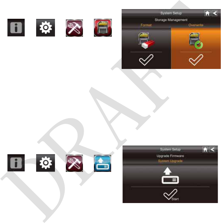
System Upgrade
To upgrade the firmware from the vendor website, you must download and store it in the
SD card root directory.
From the pop-up menu, tap the following
icons
The screen displays:
ÎÎÎ
Press the Start button to upgrade the firmware.
33
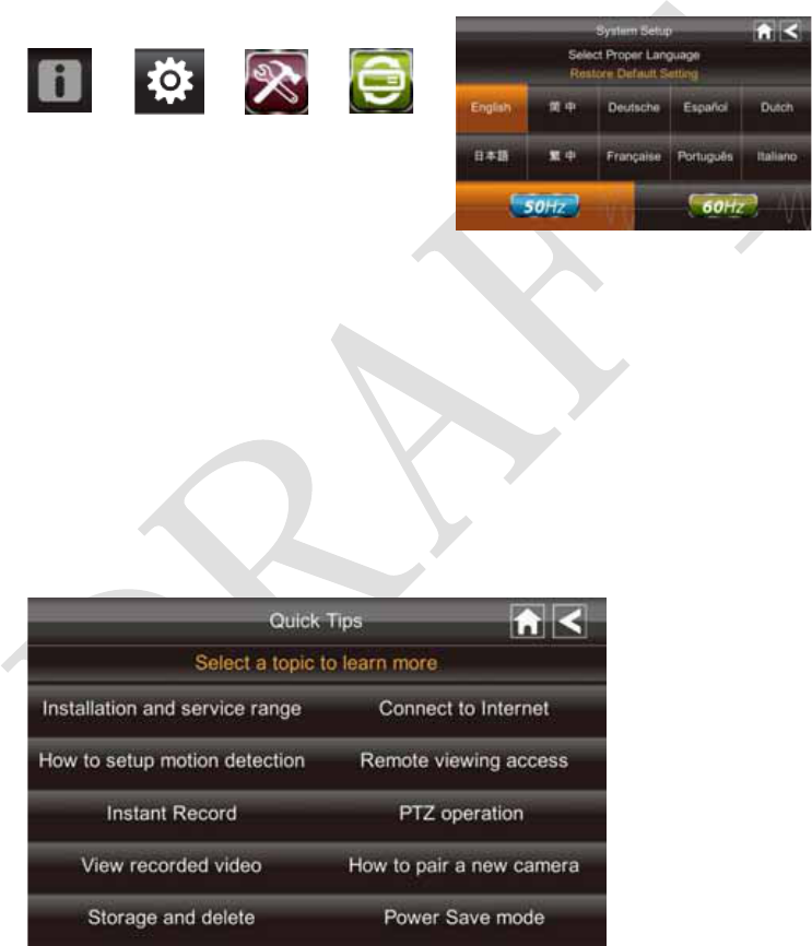
Language
English is the default language. If you change the language, all system settings default to
the original factory settings. You will have to reenter any specialized settings.
From the pop-up menu, tap the following
icons
The screen displays:
ÎÎÎ
1. Select the language required. The Restore Default Settings screen displays.
2. Tap OK to continue. The system will shut down in about 5 seconds.
3. When the system restarts, it will ask you to perform the touch screen calibration.
Follow the instructions on the screen.
4. Select the frequency setting by tapping the frequency icon (50Hz /60Hz). Make sure
the frequency setting complies with local electrical regulations.
Note: In general the frequency for Europe is 220-240 volt, at 50 hertz frequency
Quick Tips
The Quick Tips screen provides additional details on important subjects of system
operation. Tap on a subject to display the information.

34
REMOTE ACCESS
Overview
This DWH Series Video Security System lets you view live video from your iPhone, iPad,
or Android smartphone or tablet. Free apps are available through the iTunes App Store or
the Android Market.
Up to 2 remote users can access live video at the same time as long as they have the User
ID (DID) code and security code.
Downloading Android APP
From your Android smart phone or tablet device, go to the Android Market and search for
OMGuard.
Downloading iPhone APP
From your iPhone or iPad, go to the iTunes App Store and search for OMGuard
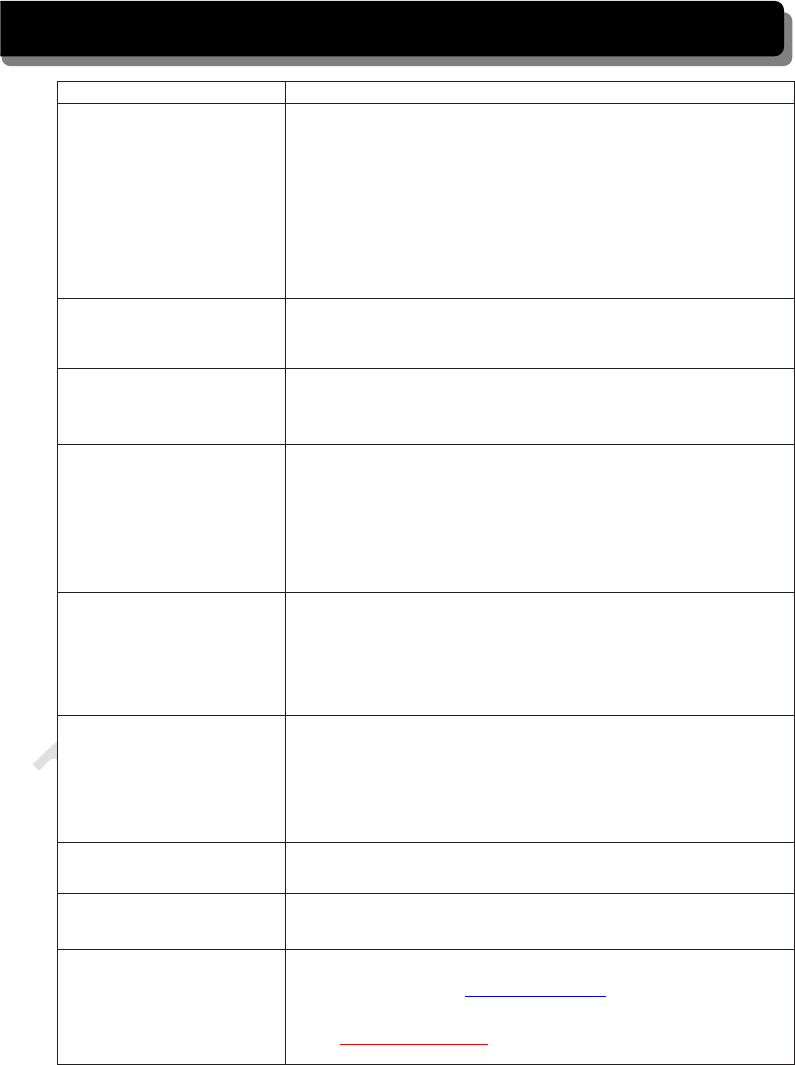
Connecting to the Internet
The docking cradle charges your monitor as well as provides an internet connection.
When you are connected to the internet, live video will continue to display on the monitor,
but monitor's touch operation will become limited.
Monitor's touch operation will resume normal after disconnecting from the internet by
select Charge Only option from the pop up menu, or remove monitor from the docking
cradle.
1. Connect the AC adapter to the docking cradle.
2. Connect the RJ45 (Ethernet) cable from the back of the cradle to your primary router
(from your internet service provider).
3. Insert the monitor into the cradle. A screen asks if you want to connect to the internet
or only charge the monitor.
35
4. Tap Connect. The Internet Connection Status Indicator appears on the upper left of
the Live screen indicating that the system is connected to the internet.
You can now view live video through your mobile devices.
>> While the system is connected to the internet, the LIVE screen display rate may
reduce to 2 - 3 frames per second.
5. When you connect remotely to the monitor, the Internet Connection Status Indicator
shows that remote view is in progress.
>> Once internet connectivity is set, the system will memorize the setting and the
next time you place the monitor back into the cradle, the system will automatically
connect to the internet."
Connecting to the Intranet (Home Network)
When the monitor is placed in the cradle and "charge only" is selected, you can still access
your live video from smartphone(s) or tablet(s) as long as those devices are also connected
to the same network as the monitor. For example, your smartphone is connected to your
home network via WiFi, in this case, live video will still be displayed on the monitor as
well as on the smartphone.
Receiver
Power Supply
Adaptor
5

36
MAINTAINING YOUR SYSTEM
Please make sure to upgrade your system firmware to the latest version. Check your
system firmware version on the Network Information screen (please refer to the Network
Information section).
Go to vendor website to check the current firmware version. Compare it with your system
firmware version. If you need to upgrade your system firmware, download the latest
firmware version to your SD card and then upgrade that firmware version to the monitor.
1. Eject the SD card from the monitor.
2. Place the SD card into a USB card reader/writer (not included with the purchased
package).
3. Connect the flash drive to your PC.
4. Copy the latest firmware version from vendor website to your SD card root directory.
5. Remove the SD card and reinsert it into the monitor.
6. Upgrade the firmware (please refer to the System Upgrade section).
37
TROUBLE SHOOTING
TROUBLE SOLUTIONS
No image Screen lock may be on. Tap the Power button to unlock the
screen.
Make sure the camera is power on.
Make sure the monitor has enough charge / connect it to
AC/DC adaptor.
Move the camera closer to the monitor; it might be out of
range or flip the antenna of the receiver to obtain best
possible reception.
Poor picture quality Flip the antenna of the receiver to obtain best possible
reception.
Clean the camera lens usin
g
lens cleanin
g
cloth.
The motion sensor not
working
Increase or decrease the sensitivity of the motion sensor
(please refer to the Motion Detection section).
Check the settings on the RECORD screen.
No recording happens
although it has the
schedule set.
Ensure correct DATE AND TIME has been set and the
Record Schedule setup correctly.
Ensure the memory card is inserted into DVR and formatted.
There might be no movement detected,
i.e.: no moving object to trigger the motion sensor.
Unable to pair the camera
to the receiver
Make sure the camera is power on.
Press and release the pairing button quickly. Do not press and
hold.
Power off the receiver and restart. If power button does not
respond, use a pin to press the reset button.
A white image appears at
night
The camera's infra-red LEDs shine invisible light that reflects
of surfaces such as glass will cause white light. Place the
camera on the other side of windows to improve the night
vision or place it in a well-lit area (recommend to install a
security lamp to improve lighting).
LIVE screen has no icons. Screen lock may be on. Tap the Power button to unlock the
screen.
System locked up Power off the receiver and restart. If power button does not
respond, use a pin to press the reset button.
Unable to use the
Windows Media Player
to play the video
clips from the SD card
The video files play with a Quicktime® player. Download
this free player from www.apple.com . You can also
download the alternative free player, VLC Media Player,
from www.videolan.org. Ensure your PC has SD card reader.
38
PRODUCT SPECIFICATION
Camera Receiver
Maximum channels - 4
Communication Range 150 meters in open space
LCD Monitor Resolution 800 x 480
Camera Resolution Single Camera: 480x272 / Multiple Camera: 320x240
Operating Temperature -10堕C ~ 50堕C
Operating Voltage DC 5V / 1A
Current Consumption 500mA (MAX) 800mA (MAX)
Night Vision 8 meters
Dimension 151x74x49 mm 184x128x28 mm
Recording Time for Memory Card (32GB max)
SD Card Capacity Single Camera
(Full Screen)
Multiple Cameras
(QUAD Mode)
1GB 200 Minutes 130 Minutes
2GB 400 Minutes 260 Minutes
8GB 1,600 Minutes 1,040 Minutes
16GB 3,200 Minutes 2,080 Minutes
32GB 6,400 Minutes 4,160 Minutes
Note: Single camera file recorded with video/audio; multiple camera file recorded with
video only.

FCC NOTE:
This device complies with Part 15 of the FCC Rules.
Operation is subject to the following two conditions: (1) this device may not cause
harmful interference, and (2) this devi ce must accept any interference received,
including interference that may cause undesired operation.
THE MANUFACTURER IS NOT RESP ONSIBLE FOR ANY RADIO OR TV
INTERFERENCE CAUSED BY UNAUTHORIZED MODIFICATIONS OR
CHANGE TO THIS EQUIPMENT. SU CH MODIFICATIONS OR CHANGE
COULD VOID THE USER’S AUTHORITY TO OPERATE THE EQUIPMENT.
This equipment has been tested and found to comply with the limits for a Class B
digital device, pursuant to part 15 of the FCC Rules. These limits are designed to
provide reasonable protection against harmful interference in a resi dential installation.
This equipment generates, uses and can radiate radio frequenc y energy and, if not
installed and used in accordance with the in structions, may cause harmful interference
to radio communications. However, there is no guarantee that interference will not
occur in a particular insta llation. If this equipment does cause harmful interference to
radio or television reception, which can be determined by turning the equipment off
and on, the user is encouraged to try to corr ect the interference by one or more of the
following measures:
-- Reorient or relocate the receiving antenna.
-- Increase the separation between the equipment and receiver.
-- Connect the equipment into an outlet on a circuit different from that to which the
receiver is connected.
-- Consult the dealer or an experien ced radio/TV technician for help.
To maintain compliance with FCC’s RF exposure guidelines, this equipment should be
installed and operated with a minimum distance of 20cm between the radiator and your
body.