JSW Pacific RC-820 Radio Clock With Hidden Camera User Manual UserManual RC820 730R Cover
JSW Pacific Corporation Radio Clock With Hidden Camera UserManual RC820 730R Cover
UserManual.wiki
>
JSW Pacific
>
RC 820 User Manual
USer Manual
Navigation menu
Upload a User Manual
Namespaces
Wiki Guide
HTML
PDF
Info
Views
User Manual
Discussion / Help
Navigation
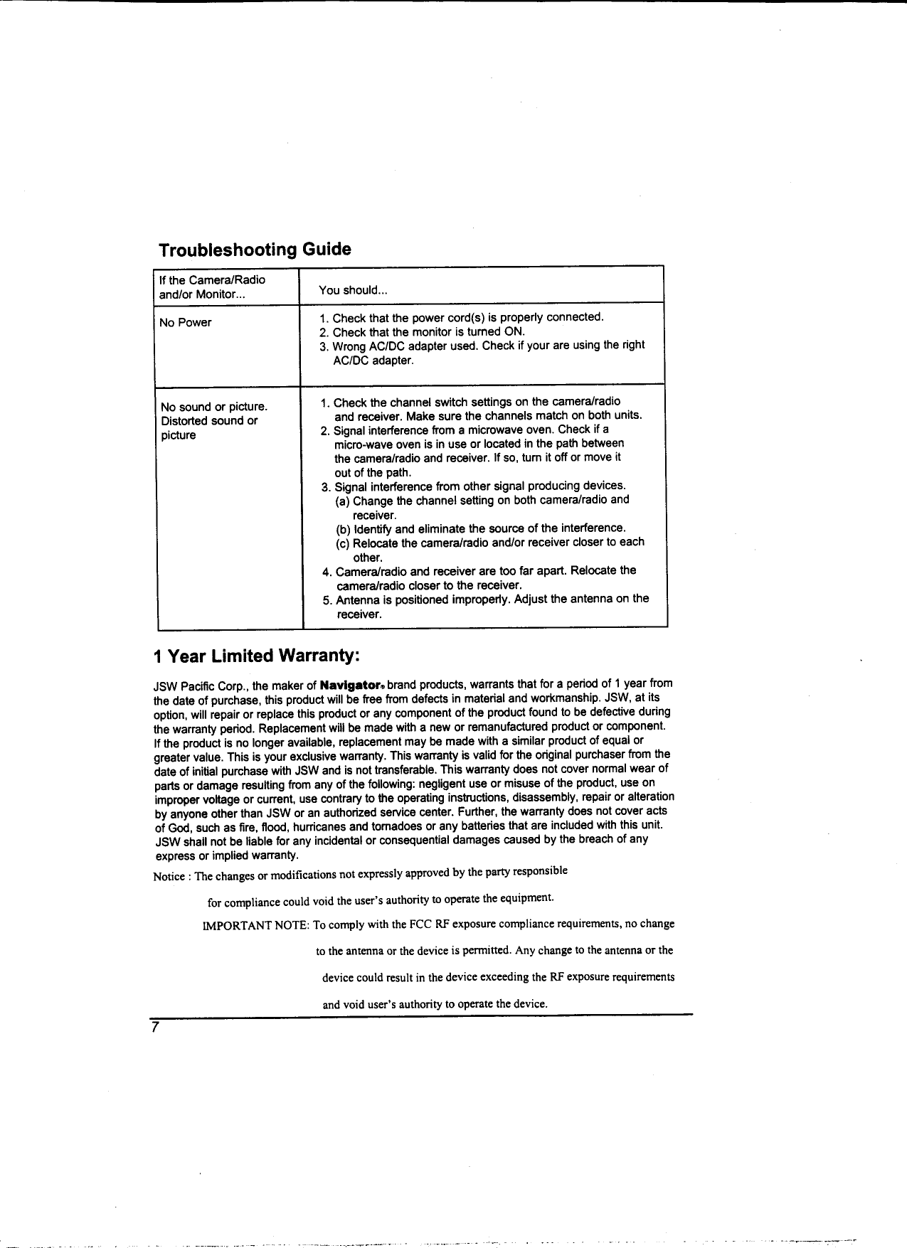
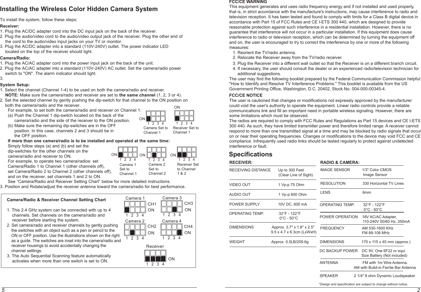
![1 6Rotating the Antenna for Best PerformanceThis system broadcasts its high-quality audio and video using directional antenna. The antenna can rotate in either clockwise or counterclockwise directions to obtain the best signal and picture clarity. In most situations, additional adjusting of the antenna may be necessary to get optimal performance. If the camera/radio and receiver are less than 10 feet apart, leave the antenna in the closed (down) position. See the instructions shown on the right to rotate the antenna. The Auto Sequence FeatureThe Wireless Color Hidden Camera System can be set up to monitor a series of rooms in ahome or office. The receiver can connect up to four cameras on four different channels forboth Audio/Video reception, and display them in auto sequence. The system has dip-switchesfor 4 channels to allow various monitoring options.When the channel dip-switches are set in the "ON" position, that channel is active on the receiver and can be seen on the TV or monitor. Channel dip-switches in the "OFF" position are inactive and will not be shown on the TV or monitor.The auto-sequence feature is activated when more than one channel is switched ON. The channels switched ON will display on the monitor at five second intervals. For example, if you have two cameras, one set to Channel 1 and the other set to channel 3, the dip-switch on the receiver must be set for both channels 1 and 3. Then camera one [CH1] and camera two [CH3] will start to display on the TV or monitor in sequence at five seconds intervals. This interval time is preset by the factory and cannot be adjusted by the user.To stop the auto-sequence function:Slide the dip-switch of the channel(s) you do not want displayedto OFF on both that camera and the receiver. Channels in the OFF position will no longer be displayed.Connecting the Receiver to a TV or MonitorThe receiver has an audio/video output which is for transferring the picture and sound fromthe camera/radio to a TV or monitor. Connect the A/V outputs to the A/V input on a TV or monitor for a screen display, or connect the A/V outputs to the A/V inputs on a VCR to record transmissions from the camera/radio.Important Safety PrecautionsPlease read before InstallingCongratulations on your purchase of the 2.4GHz Wireless Color Hidden Camera with AM/FM Radio Alarm Clock System. Please read these safety and operating instructions carefully before installing and using this system. - Keep the camera/radio, receiver, AC/AC and AC/DC adapter cords out of reach of children. - Do not place the camera/radio, receiver, AC/AC or AC/DC adapter cords in a crib or playpen. - Do not use the camera/radio near water or damp and wet environments, such as a bathtub, laundry tub, kitchen sink, or wet basements. - Locate the camera/radio, receiver, AC/AC and AC/DC adapters where there is adequate ventilation. Do not locate the camera/radio in direct sunlight. - Do not locate the camera/radio, receiver, AC/AC and AC/DC adapters near heat sources such as heat registers, radiators, ovens, furnaces or other appliances with high operating temperatures. - Do not use with extension cords. Use only the AC/AC and AC/DC adapters provided with this system. Use of other adapters may damage the units and void your warranty. - Only plug components into standard household voltage outlets (110V - 240V AC, 50Hz or 60 Hz). - Do not place cords from the AC/AC and AC/DC adapters and camera/radio, receiver where they can be pinched or stepped on. Protect the cords by keeping them out of the way of children, pets and routine household traffic. Do not place heavy objects on power cords or cover cords with rugs or carpet. - When cleaning, use a DRY, lint-free cloth. Unplug the camera/radio, receiver, AC/AC and AC/DC adapters before cleaning. NEVER immerse any components in water and do not spray cleaners or solvents on the units. Doing so may damage the units or cause electrical shock. - Unplug the AC/AC and AC/DC adapters from the wall outlet when the system is not in use. - Mishandling, alterations or modifications not approved by the manufacturer will void the warranty. CAUTION! - Connect this unit ONLY to other compatible units. Do not connect it to any other type of alarm or auxiliary device. Connecting anything else to this unit may damage it or prevent it from operating properly. CAUTION! - Do not paint over the camera. CAUTION! - This system uses public airwaves for wireless operation. The sound and video may be broadcast to and picked up by other 2.4 GHz receiving devices. Conversations and images from other rooms near the camera may be broadcast and picked up. To protect your privacy.Additional Notice- Do not place video monitor or equipment on an unstable cart, stand or table. The video monitor or equipment may fall causing serious injury to a child or adult.1 2 3 4OFFON1 2 3 4OFFONChannel Dip-SwitchDiagram Channel 1 ONChannel Dip-Switch DiagramChannel 1 & 3 ON360ºUp/Down 90ºReceiver](https://usermanual.wiki/JSW-Pacific/RC-820/User-Guide-321491-Page-3.png)


![1 6Rotating the Antenna for Best PerformanceThis system broadcasts its high-quality audio and video using directional antenna. The antenna can rotate in either clockwise or counterclockwise directions to obtain the best signal and picture clarity. In most situations, additional adjusting of the antenna may be necessary to get optimal performance. If the camera/radio and receiver are less than 10 feet apart, leave the antenna in the closed (down) position. See the instructions shown on the right to rotate the antenna. The Auto Sequence FeatureThe Wireless Color Hidden Camera System can be set up to monitor a series of rooms in ahome or office. The receiver can connect up to four cameras on four different channels forboth Audio/Video reception, and display them in auto sequence. The system has dip-switchesfor 4 channels to allow various monitoring options.When the channel dip-switches are set in the "ON" position, that channel is active on the receiver and can be seen on the TV or monitor. Channel dip-switches in the "OFF" position are inactive and will not be shown on the TV or monitor.The auto-sequence feature is activated when more than one channel is switched ON. The channels switched ON will display on the monitor at five second intervals. For example, if you have two cameras, one set to Channel 1 and the other set to channel 3, the dip-switch on the receiver must be set for both channels 1 and 3. Then camera one [CH1] and camera two [CH3] will start to display on the TV or monitor in sequence at five seconds intervals. This interval time is preset by the factory and cannot be adjusted by the user.To stop the auto-sequence function:Slide the dip-switch of the channel(s) you do not want displayedto OFF on both that camera and the receiver. Channels in the OFF position will no longer be displayed.Connecting the Receiver to a TV or MonitorThe receiver has an audio/video output which is for transferring the picture and sound fromthe camera/radio to a TV or monitor. Connect the A/V outputs to the A/V input on a TV or monitor for a screen display, or connect the A/V outputs to the A/V inputs on a VCR to record transmissions from the camera/radio.Important Safety PrecautionsPlease read before InstallingCongratulations on your purchase of the 2.4GHz Wireless Color Hidden Camera with AM/FM Radio Alarm Clock System. Please read these safety and operating instructions carefully before installing and using this system. - Keep the camera/radio, receiver, AC/AC and AC/DC adapter cords out of reach of children. - Do not place the camera/radio, receiver, AC/AC or AC/DC adapter cords in a crib or playpen. - Do not use the camera/radio near water or damp and wet environments, such as a bathtub, laundry tub, kitchen sink, or wet basements. - Locate the camera/radio, receiver, AC/AC and AC/DC adapters where there is adequate ventilation. Do not locate the camera/radio in direct sunlight. - Do not locate the camera/radio, receiver, AC/AC and AC/DC adapters near heat sources such as heat registers, radiators, ovens, furnaces or other appliances with high operating temperatures. - Do not use with extension cords. Use only the AC/AC and AC/DC adapters provided with this system. Use of other adapters may damage the units and void your warranty. - Only plug components into standard household voltage outlets (110V - 240V AC, 50Hz or 60 Hz). - Do not place cords from the AC/AC and AC/DC adapters and camera/radio, receiver where they can be pinched or stepped on. Protect the cords by keeping them out of the way of children, pets and routine household traffic. Do not place heavy objects on power cords or cover cords with rugs or carpet. - When cleaning, use a DRY, lint-free cloth. Unplug the camera/radio, receiver, AC/AC and AC/DC adapters before cleaning. NEVER immerse any components in water and do not spray cleaners or solvents on the units. Doing so may damage the units or cause electrical shock. - Unplug the AC/AC and AC/DC adapters from the wall outlet when the system is not in use. - Mishandling, alterations or modifications not approved by the manufacturer will void the warranty. CAUTION! - Connect this unit ONLY to other compatible units. Do not connect it to any other type of alarm or auxiliary device. Connecting anything else to this unit may damage it or prevent it from operating properly. CAUTION! - Do not paint over the camera. CAUTION! - This system uses public airwaves for wireless operation. The sound and video may be broadcast to and picked up by other 2.4 GHz receiving devices. Conversations and images from other rooms near the camera may be broadcast and picked up. To protect your privacy.Additional Notice- Do not place video monitor or equipment on an unstable cart, stand or table. The video monitor or equipment may fall causing serious injury to a child or adult.1 2 3 4OFFON1 2 3 4OFFONChannel Dip-SwitchDiagram Channel 1 ONChannel Dip-Switch DiagramChannel 1 & 3 ON360ºUp/Down 90ºReceiver](https://usermanual.wiki/JSW-Pacific/RC-820/User-Guide-321491-Page-8.png)