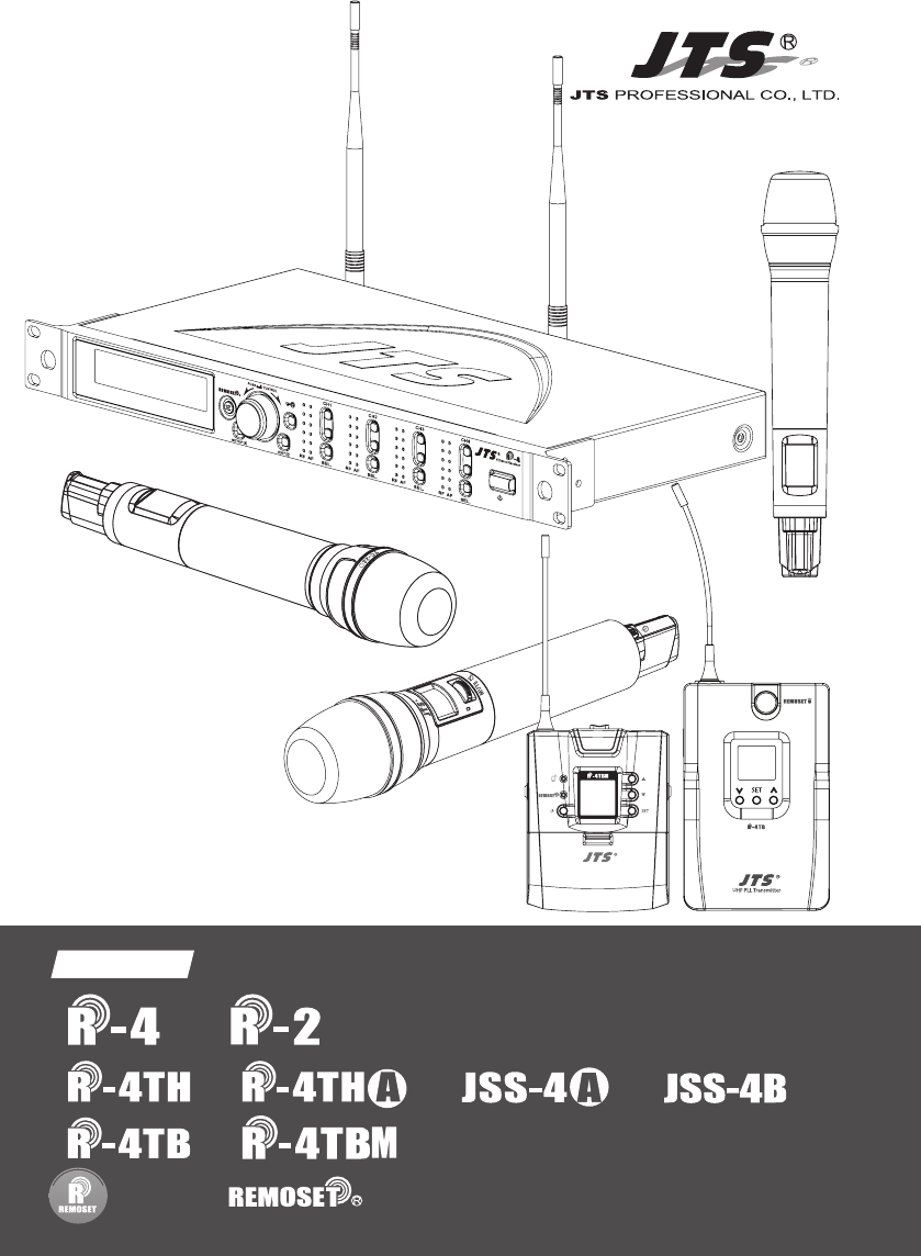
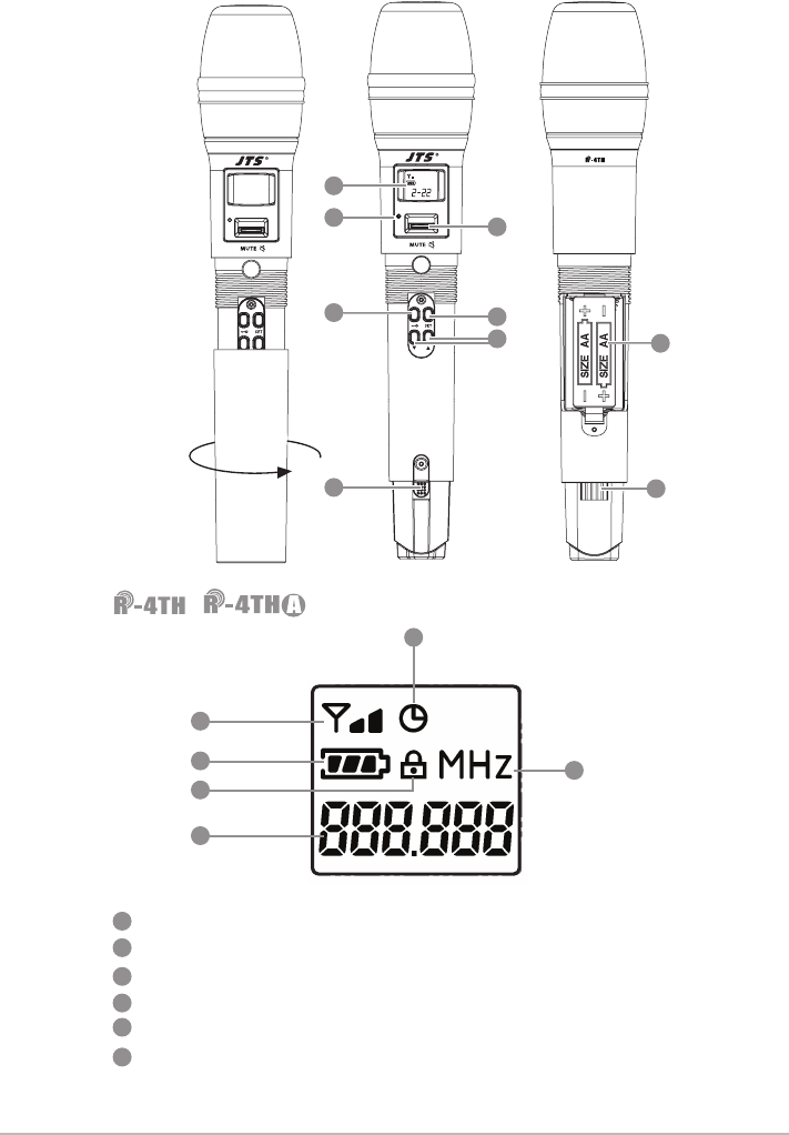
JTS Professional Co R-4 Wireless Microphone Receiver User Manual
JTS Professional Co Ltd Wireless Microphone Receiver
user manual
59508-085-01
PROFESSIONAL CO., LTD
www.jts.com.tw
/
/
/
/ /
Instruction Manual
UHF PLL
With JTS 2.4G RF Synchronizing Technology
UHF PLL Transmitter
-12dB
IDoff
633.875 MHz
G: 1 C: 11
UF-20TB
AT
Hi

1. The warranty card must be presented with the date of purchase and attached at
the bottom of the machine to ensure the validity of warranty service.
2. The warranty is valid for one year starting from the date of purchase shown on
''warranty label'' attached to the product; alternatively, the warranty is valid for 15
months starting from the date the product was manufactured if the ''warranty label''
is missing on the machine. If the microphone is returned for service but with the
machine, the warranty is valid for 15 months starting from the date of manufacturing
shown on the microphone.
3. If malfunction occurs under normal operations according to the instruction manual
while the warranty is still valid, please call the shop where you purchased the
product for warranty service.
4. It is important to return both the machine and microphone back to the shop for
service, since this makes it easier to identify where the possible problem is and
determine whether a service fee is needed.
5. JTS will provide service free of charge while the warranty is still valid. However, A fee
for parts and/or service may be charged for the following:
a. Damage due to natural disaster or any other irresistible factors;
b. Damage due to dropping, immersion in water, exposure to high humidity,
corrosion, ingress of alien objects, or loss of parts;
c. Consumables are not part of the warranty; or
d. The ''warranty label'' is not found on the machine or the ''warranty label'' is
damaged to the point that the validity of warranty is not recognizable.
6. Keep this warranty card at a safe place, as the warranty is invalid with a lost
warranty card.
One-Year Warranty Card
Product model Serial number
Customer Phone number
Address
Date of purchase
Distributor’s
shop seal
The distributor’s shop seal and date of purchase are
required for the warranty to be valid!
Warranty Service
Contents
1. Notes for system operations
2 . F e a t u r e s
3. Specications
3-1 UHF PLL 4-channel / 2-channel, diversity receiver
3-2 UHF PLL handheld transmitter
3-3 UHF PLL body-pack transmitter
3-4 Optional Condenser Microphon
4. Parts
4-1 UHF PLL 4-channel / 2-channel, diversity receiver // /
4-2 UHF PLL handheld transmitter // /
4-3 UHF PLL handheld transmitter// /
4-4 UHF PLL body-pack transmitter //
4-5 UHF PLL body-pack transmitter //
4-6 Accessories
4-7 Microphone Choices
5. Connection
5-1 Connecting transmitter
5-2 Installing transmitter // /
5-3 Installing transmitter // /
5-4 Installing transmitter //
5-5 Installing transmitter //
6. Operation
6-1 Operation // /
6-2 Operation // /
6-3 Operation // /
6-4 Operation //
6-5 Operation //
7. Digital Code Alert Function
8. Notes for the product
1
1
2
2
3
5
7
9
9
13
15
17
19
21
21
24
24
26
27
27
28
29
29
37
40
46
49
55
56

1
1. Notes for system operations
2. Features
• Before connecting to the main power supply, check that the
power requirements shown on the nameplate of the machine
meet the output of the adaptor.
• Do not place the machine at a place where high temperature
and humidity are expected.
• Do not operate the system with wet hands.
• Keep the machine away from any heat or ignition source.
• Before setting up the machine, make sure that the volume is
set at the minimum for both the mixer and amplier.
• The system features the latest anti-interference digital code
circuit design that is proven to isolate the interference
between the system and the outside world.
• Up to 36MHz of bandwidth with a maximum of 1440 channels
to choose from
• Adjustable squelch level
• Default with 6 groups, up to 22 available
• User-dened groups provided
• Automatic scan
• Provided with antenna booster power
• JTS patent: the latest RF allows the transmission of
not only frequency, but also data such as sensitivity, low cut,
transmission power and key lock to the transmitter.
• With one push of the key, upto four transmitters
can be synchronized.
• RF ''no signal'' alert on LCD display
• AF ''microphone mute'' alert on LCD display
• Transmitter ''low battery'' alert on LCD display
• Antenna and power cascading for improved performance
and convenience.
• Digicode prevents intermodulation
2
3.Specications
3-1 UHF PLL 4-channel / 2-channel, diversity receiver
Model
Frequency oscillation Phase-locked loop, PLL
Carrier frequency 470~960 MHz
No. of channels 4 channels 2 channels
Channel pairing RF
Diversity antenna diversity
Bandwidth 36MHz
Signal/noise ratio >106dB(A)
Total harmonic
distortion
<0.5%@1KHz
Receiving sensitivity -95dBm,S/N>80dB
Mirror rejection ratio >80 dB
General frequency
response
50Hz~18KHz±2dB
Antenna connector BNC female
Antenna booster
power DC12V/100mA
Display LCD
Functions displayed Group, channels, frequency, transmitter power, antenna A/B,
mute, AF, RF, channel scan, output level, volume, Device ID
Controls
Power ON/OFF, groups, channels, frequency, receiving
sensitivity, key lock, volume, output attenuation (XLR),
channel scan (ON/OFF), antenna power, display setting
Audio output level
Ref:±22.5KHz Dev@1KHz Tone
ψ6.3 Phone Jack:-10dBV
XLR Jack:-4dBV(Line)、-24dBV(MIC)
Audio output
impedance
600Ω
Mute Noise mute and Pilot Tone
Output port 5 balance XLR ports,
1 unbalance φ6.3mm jack
3 balance XLR ports,
1 unbalance φ6.3mm jack
Power 100~240VAC
Dimensions 485mm L x 230mm W x 44mm H
Remark Specications provided above may be slightly different from
the product without further notice.
3
3-2 UHF PLL handheld transmitter
Model /
Frequency oscillation Phase-locked loop, PLL
Carrier frequency 470~960MHz
Bandwidth 108MHz as per local regulation
Paring RF Remoset
RF power output 10mW/50mW(as per local regulation)
RF stability <±10KHz@Fc
Modulation frequency
deviation
±48KHz
Spurious Emissions <-50dBc
LCD display
Group, channels, frequency, mute, auto off, input
level attenuation, sensitivity adjustment, power
indication, Device ID
Controls
Power, mute, groups, channels, frequency,
sensitivity adjustment, input level attenuation,
auto off, transmission power, key lock
Battery AA Alkaline battery x 2
Charging Yes
Dimension 265mm L x 51.2mm W x 51.2mm H
Remark Specications provided above may be slightly
different from the product without further notice.
Model /
Frequency oscillation Phase-locked loop, PLL
Carrier frequency UHF 470~960 MHz
Bandwidth 108 MHz as per local regulation
Pairing RF Remoset
RF power output 10mW / 50mW (as per local regulation)
RF output Hi / Lo adjustable
Stability <0.005%
Frequency deviation ±48kHz
LCD display
Group and channel, frequency, power indication,
transmission power, sensitivity, Device ID, username,
gain, low cut
Controls
Power ON/OFF, frequency setting, group, sensitivity,
bass attenuation, pairing ID, frequency pairing,
transmission power adjustment, display contrast,
backlight time setting, Chinese/English selection, key
lock pattern, mute, reset
Harmonic radiation <-50 dBC

4
Audio frequency
response 50KHz~18KHz
Capsule Module Interchangeable
Battery AA Alkaline battery x 2 / rechargeable battery x 2
Charger CH-2,CH-8
Dimensions 35.5mm L x 50mm W x 253mm H
Remark
Specications provided above may be slightly
different from the product without further
notice.
5
Model
Frequency oscillation Phase-locked loop, PLL
Carrier frequency 470~960MHz
Bandwidth 108MHz as per local regulation
Paring RF Remoset
RF power output 10mW/50mW(as per local regulation)
RF stability <±10KHz
Modulation frequency
deviation
±48KHz(Peak)
Spurious Emissions <-50dBc
LCD display
Group, channels, frequency, mute, auto off, input level
attenuation, sensitivity adjustment, power indication,
Device ID
Controls
Power, mute, groups, channels, frequency, sensitivity
adjustment, input level attenuation, auto off, transmission
power, key lock
Input connector 4-pin mini XLR
Controls Power, mute, group, channel, frequency, sensitivity
adjustment, input level attenuation, auto off
Battery AA Alkaline battery x 2
Charger CH-2 CH-8
Dimension 62.3mm L x 20mm W x 97mm H
Remark Specications provided above may be slightly different
from the product without further notice.
3-3 UHF PLL body-pack transmitter
6
Model
Frequency oscillation PLL Synthesized Control
Carrier frequency UHF 470~960 MHz
Bandwidth 108MHz as per local regulation
Rf power outputs Low / High
RF stability <±10KHz
Modulation frequency
deviation
±48KHz (Peak)
Chassis Aluminium alloy
Lcd display Group, Channel, Frequency, Battery Status, GAIN Adjust
Controls Power ON/OFF, AF Level, Frequency (Up/Down), Lock-on
Mode, REMOSET ID, RF Output Adjust
Input connector 4P Mini XLR
Spurious emissions <-50 dBC
Audio frequency response 50Hz~18k Hz
Battery AA NiMH x2
Dimension 62mm W x 80.3mm H x 22.6mm D
Weight 93g
7
3-4 Optional Condenser microphone
Lavaliere microphone
Headset microphone
Model CM-501 CM-201i CM-125i
Output
connector
4-pin mini XLR
Frequency
response
100~15,000 Hz 60~15,000 Hz 50~18,000 Hz
Directionality Cardioid
directionality
Omni-directionality
Sensitivity -60 ± 3dB -60 ± 3dB -53 ± 3dB
Output
impedance
2.2K Ω 4.4K Ω
Max. sound
pressure allowed
130dB
Dimension (mm) Ø10.1mm W x
26.4mm H
Ø5mm W x 9mm H Ø4mm W x 11mm H
Weight 21.5g 20.7g 7g (cable not
included)
Model CM-214i CM-214Ui CM-214ULi
Output
connector
4-pin mini XLR 4P/3P mini
XLR/3.5stereo jack
Output
connector
(optional)
3P Mini XLR/3.5 stereo plug/4P Hirose
jack
4P Hirose jack
Frequency
response
60~15,000 Hz 30~18,000 Hz 100~18,000 Hz
Directionality Omni-directionality Cardioid directionality
Sensitivity -60 ± 3dB -68 ± 3dB -75 ± 3dB
Output
impedance
1.8kΩ 680Ω 1.8kΩ
Max. sound
pressure allowed
130dB 120dB
Dimension (mm)
157mm L x
125mm W x
134mm H
157mm L x
205mm W x
134mm H
157mm L x
125mm W x
134mm H
Weight 32.9g 38.4g 18g (cable not
included)
8
Ear-hook microphone
Model CM-235i CX-504
Output
connector
4P-pin mini XLR
Output
connector
(optional)
3P Mini XLR/3.5 ste-
reo plug/4P Hirose
jack
Frequency
response
50~18,000 Hz 30~18,000 Hz
Directionality Omni-directionality Cardioid
directionality
Sensitivity -53 ± 3dB -68 ± 3dB
Output
impedance
1.8kΩ 680Ω
Max. sound
pressure
allowed
130dB
Dimensions
(mm)
157mm L x
155mmWx
134mmW
111.3mm L x
285mmWx
55mmW
Weight 17g 56.3g
Model CM-801 / CM-804i CM-8015 / CM-825i
Output
connector
4-pin mini XLR
Output
connector
(optional)
3P Mini XLR/3.5 stereo plug/4P Hirose jack
Frequency
response
60~15,000 Hz 50~18,000 Hz
Directionality Omni-directionality
Sensitivity -64 ± 3dB -53 ± 3dB
Output
impedance
1.8KΩ
Max. sound
pressure
allowed
130dB
9
4. Parts
1
4
2
3
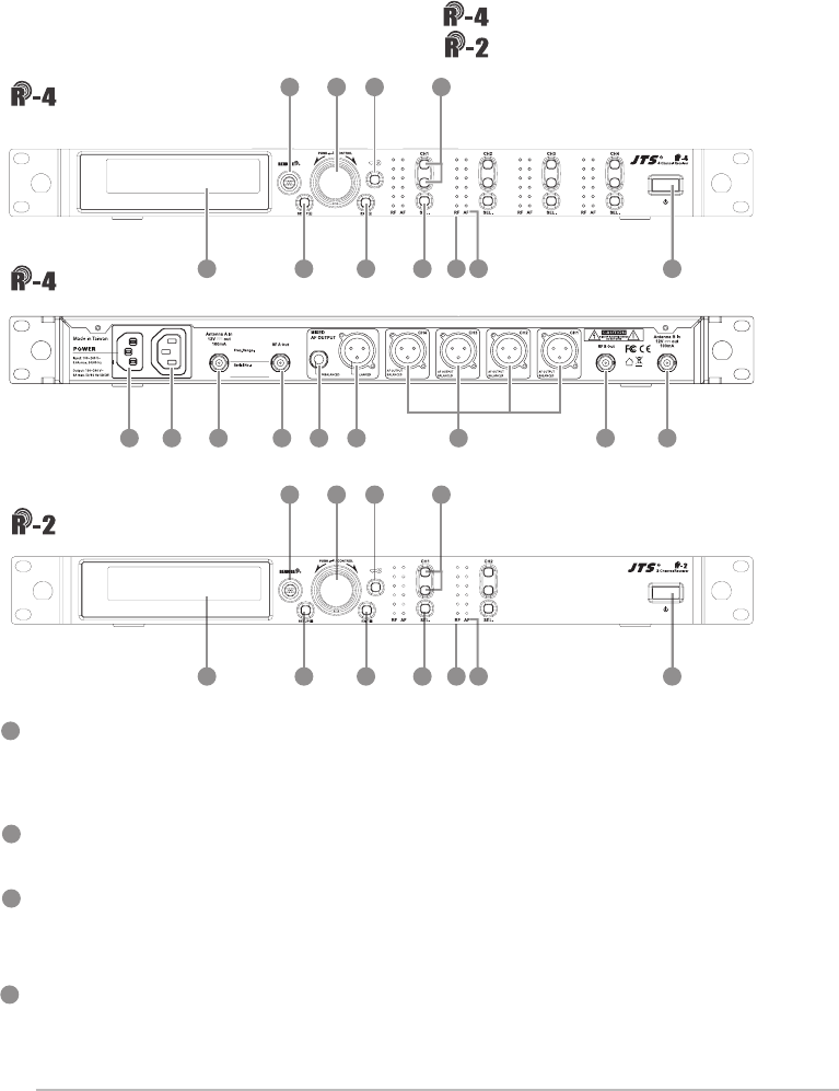
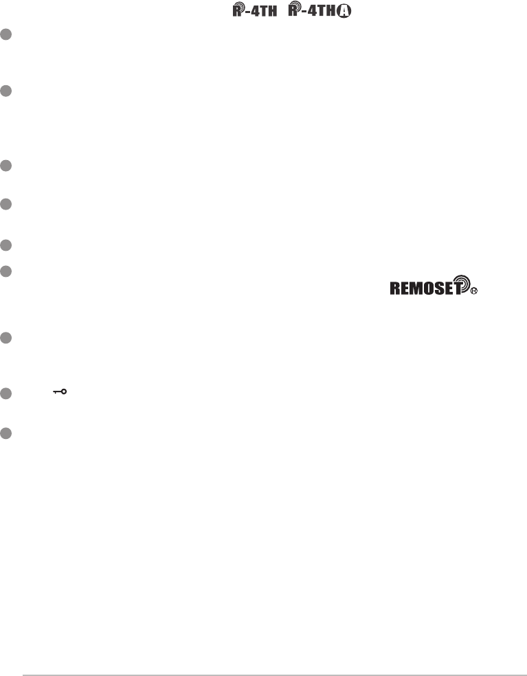
Power ON/OFF:ON:push once to turn on
OFF:push and hold until ''Power OFF'' is shown on the
LCD to turn off.
EXIT:Push exit to cancel a selection or exit from the current menu when
R-4/2 is in the ''setting menu.''
Rotary Switch:when in the ''function menu,'' turn the switch to select the
desired function; push the switch (or SETUP) to enter the selection and
spin the switch to select the setting. Push [SETUP] to save the setting.
SETUP:Push and hold for 2 seconds to enter the vsetting menu.'' Push
SETUP to save the setting once the selection and setting are made
according to ''3. Rotary Switch.''
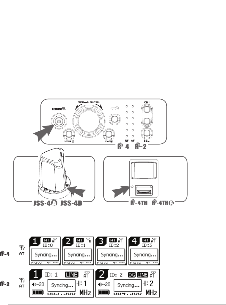
Front panel
Rear panel
9
9
11
11
1
1
3
3
2
2
5
5
7
7
4
4
8
8
6
6
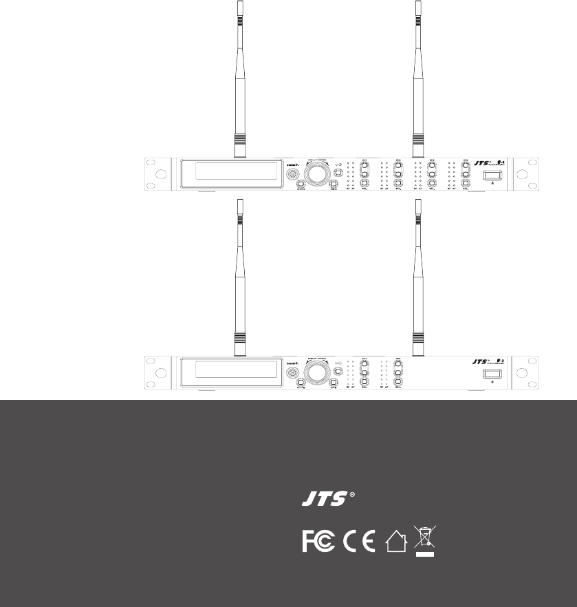
4-1 UHF PLL 4-channel diversity receiver //
10
10
Front panel
UHF PLL 2-channel diversity receiver //
14
16 1617 1715 14a
13
12

10
9
5
6
7
8
REMOSET:When the receiver setting is done, push to
transmit the setting data to the handheld or body-pack transmitter.
LCD display:See ''Receiver LCD display instructions.''
AF: indicates the current strength of audio frequency signals.
RF: indicates the current strength of radio frequency signals.
Key lock: push and hold for 2 seconds to lock all keys, and again to unlock.
Volume keys:push▲/▼keys to adjust the volume between 0 and -31dB.
Selection key:push this button
a. Push SETUP to enter the setting for the selected channel for parameter
settings.
b. Push REMOSET to transmit the setting data to the transmitter in this
selected channel.
AC Power Jack:connects 100-240VAC power.
AC power cascading:use AC double power cable (optional) for power
cascading.
XLR audio jack:balanced audio signal output
XLR audio jack:balanced audio signal output after mixing
Ø6.3 audio output jack:unbalanced audio signal output after mixing
Antenna A (B) input terminal:BNC antenna input jack that also provides
DC12V/100mA output.
RF signal A (B) output terminal: RF signal output jack; it is possible to
connect the RF A (or B) OUT of the rst unit to the antenna A (or B) IN of
the second unit with a BNC-BNC signal cable, and then the RF A (or B)
OUT of the second unit to the antenna A (or B) IN of the third unit, and so
on and so forth. The cascade may consist of up to 10 units to minimize the
number of antennas used.
10
11
12
13
14
14a
15
16
17
Note: Each cascading may bring1.2dB attenuation to RF signal.
11
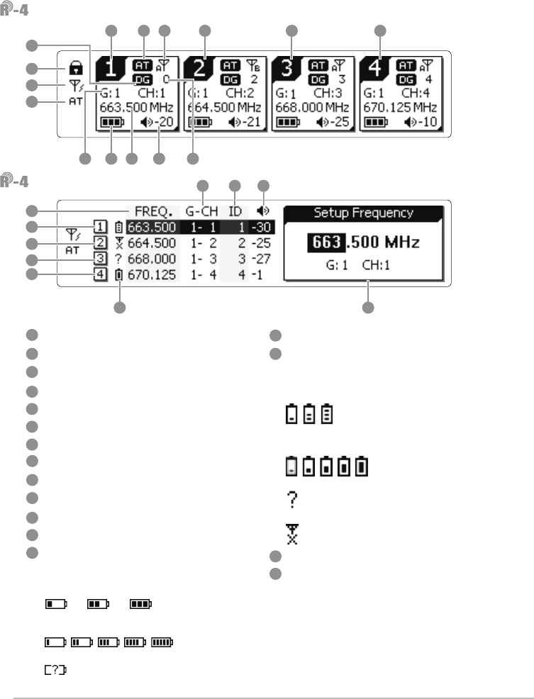
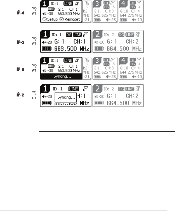
LCD displays
Setting page
Key lock
Antenna power supply ON
Mixed output attenuation ON
Receiver channel 1
Receiver channel 2
Receiver channel 3
Receiver channel 4
Output attenuation ON
Antenna selection A/B
Device ID
Group/channel
Frequency
Transmitter battery
3blocks: R-4TH/R-4THA/R-4TB
microphone is used
5blocks: JSS-4A microphone is used
:waiting for battery
information from transmitter
Volume
Transmitter battery
3blocks: R-4TH/R-4THA/R-4TB
microphone is used
5blocks: JSS-4A microphone is used
:waiting for battery information
from transmitter
:no microphone signal
Setting window
Digital code ON
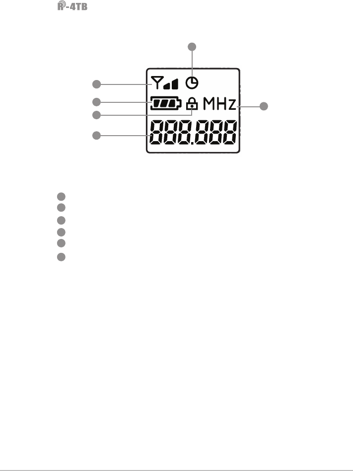
18
33
25
19
26
20
27
21
28
22
29
23
30
24
31
32
21
2930 31
3128 27
28
25 26
27
22 23 24
18
20
19
29
21
22
23
24
32 33
34
34
12
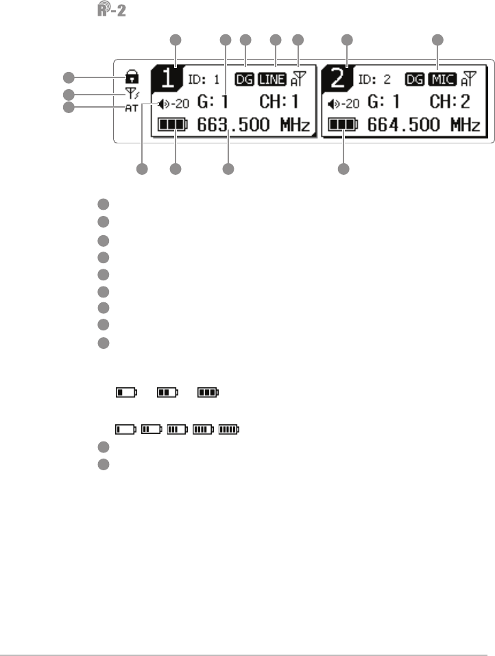
LCD displays
Key lock
Antenna power supply ON
Mixed output attenuation ON
Receiver channel
Digital code ON
Output level LINE/MIC
Antenna selection A/B
Volume
Transmitter battery
3blocks: R-4TH / R-4THA/R-4TB
microphone is used
5blocks:JSS-4A microphone is used
Group / channel
Frequency
38 39 40 41 38 4044
42
35
36
37
43 4345
41
35
42
36
43
37
44
45
38
39
40
13
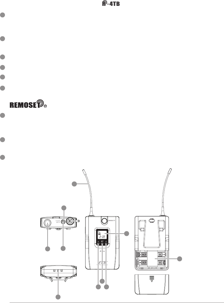
Power ON/OFF:push once to turn on. Push and hold for 2 seconds while
the power is on to turn off. While the power is on, a quick push of this
button will show the Device ID on the LCD display.
Mute:switch up to talk and down to mute while the power is on. If the
power is off, switching up from mute will turn the microphone on. In
mute, it is allowed to select 1, 10 or 30 minutes to automatically turn the
microphone off.
Battery compartment:it holds 2 UM3, AA 1.5V Alkaline batteries or MiNH
rechargeable batteries.
LED indicator:it shows the microphone's status, including battery power,
mute and pairing.
LCD display:it shows the parameter settings of transmitter.
SET:for parameter settings, including frequency, group, channel,
sensitivity, transmission frequency, auto off time, Device ID ,
function (ON/OFF).
Up/down selection keys:they are used with ''SET'' to change parameter
settings. Before entering the setting mode, a quick push will show the
Device ID on the LCD display.
LOCK :push and hold ''LOCK'' for 2 seconds to lock and again to un-
lock. Under ''LOCK'' status MUTE function is still valid.
Charging contact module: if rechargeable batteries are used, charging is
possible with the matching charger.
4-2 UHF PLL handheld transmitter // /
Note:R-4TH is the same as R-4THA except that the battery cover of the R-4THA is made of
metal.
1
4
2
3
9
5
6
7
8
14
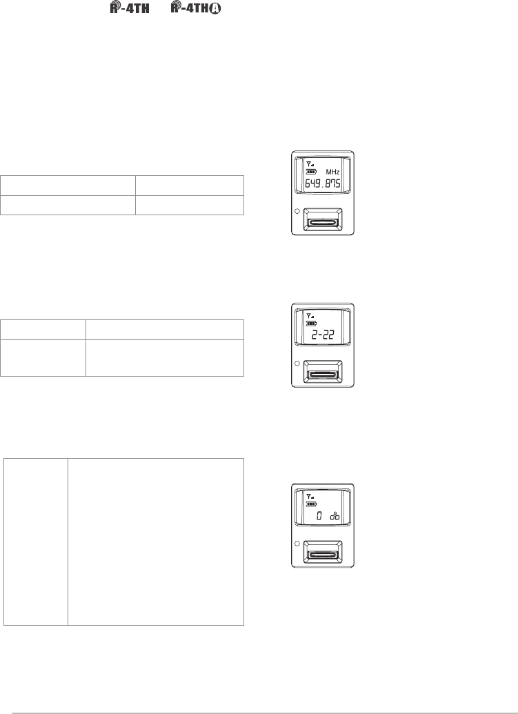
RF output power (1 block is 10mW and 2 blocks are 50mW)
Auto off ON
Battery level
Key lock
Frequency (MHz)
Indication of frequency, group and channel
/ LCD displays
1
42
3
9
5
6
7
8
10
10
11
11
12
12
13
13
14
14
15
15
15
4-3 UHF PLL handheld transmitter // /
LCD display
SET:for handheld transmitter setting and saving
▲、▼:up and down; used to select the desired item for handheld
transmitter.
Power ON/OFF
(1)Turn the handheld transmitter on
Power on: push the button once to turn on
Power off: push and hold for 1 second until the LCD display shows
''power off.''
(2)Mute:while the handheld transmitter is in use (main page on the
LCD display)
Mute:push the Power ON/OFF and the display shows ''mute.''
Unmute: push the Power ON/OFF again and the display shows
''unmute.''
(3)Exit setting menu
In the setting menu: push Power ON/OFF to return to main page.
In the function setting menu: push Power ON/OFF to return to the
setting menu, and again to return to main page.
Battery compartment
Charging contact: used with the charger (optional for CH-2 or CH-8)
Slide cover
Detachable capsule module
LED status indication
Green: Power ON
Blue: Remoset done (on for about 5 seconds)
Red: battery low
Blinking red: mute
Blinking red/green: battery low and mute
1
4
2
3
9
5
6
7
8
16
Channel number for the matching receiver
Microphone sensitivity
Device ID
RF output power
Low cut ON
Key lock
Transmitter battery
Group/channel
Frequency
/ LCD displays
18
18
1
42
9
5
6
7
8
10
10
11
11
12
12
13
13
14
14
15
15
16
16
17
17
2
3
17
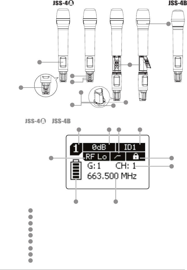
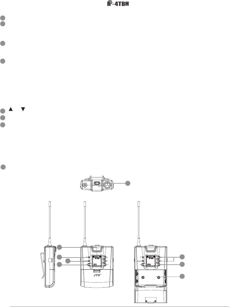
Power/mute:push once to turn the power on. While the power is on,
one quick push to mute and again to unmute. Push and hold for 2
seconds to turn off.
LED indicator: it shows the transmitter's status, including battery
power, mute and pairing.
LCDdisplay:it shows the parameter settings of transmitter.
Antenna:transmitter antenna
Microphone input :4-pin mini XLR
SET:for parameter settings, including frequency, group, channel,
sensitivity, transmission frequency, auto off time, Device ID ,
function (ON/OFF).
Up/down selection keys:they are used with ''SET'' to change
parameter settings. Before entering the setting mode, a quick push
will show the Device ID on the LCD display.
Battery compartment:it holds 2 UM3, AA 1.5V Alkaline batteries or
MiNH rechargeable batteries.
Charging contact:if rechargeable batteries are used, charging is
possible with the matching charger.
4-4 UHF PLL body-pack transmitter //
1
4
2
3
9
5
6
7
8
1
82
4
2
3
9
5
7
6
77
8
18
RF output power (1 block is 10mW and 2 blocks are 50mW)
Auto off ON
Transmitter battery
Key lock
Frequency (MHz)
Indication of frequency, group and channel
LCD displays
10
8810
11
11
12
12
13
13
14
14
15
15
19
4-5 UHF PLL body-pack transmitter //
LCD display
Battery level
Red: battery low; replace battery
REMOSET indicators
Blue: Remoset transmitting (approximately 5 seconds)
Power:
(1)On: push the power button
Off: push and hold the power button for 2 seconds till the display shows
“Power Off.”
(2)Exit Setting Menu: when in the Setting Menu, push the power button to
return to the main screen.
、 : up and down buttons for selection
SET: to set and save
Mute Switch / LED Indicator :
(1)Show green light when power is on.
(2)Show red light when battery level is too low.
(3)Flash red light when switch to ''MUTE'' function to mute the transmitter.
(4)Flash red light and green light when mute function is on and battery
level is too low.
Battery tray
UHF PLL Transmitter
-12dB
IDoff
633.875 MHz
G: 1 C: 11
UF-20TB
AT
Hi
-12dB
IDoff
633.875 MHz
G: 1 C: 11
UF-20TB
AT
Hi
-12dB
IDoff
633.875 MHz
G: 1 C: 11
AT
Hi
-12dB
IDoff
633.875 MHz
G: 1 C: 11
AT
Hi
1
1
4
4
2
2
3
3
5
5
6
6
7
7
8
8
20
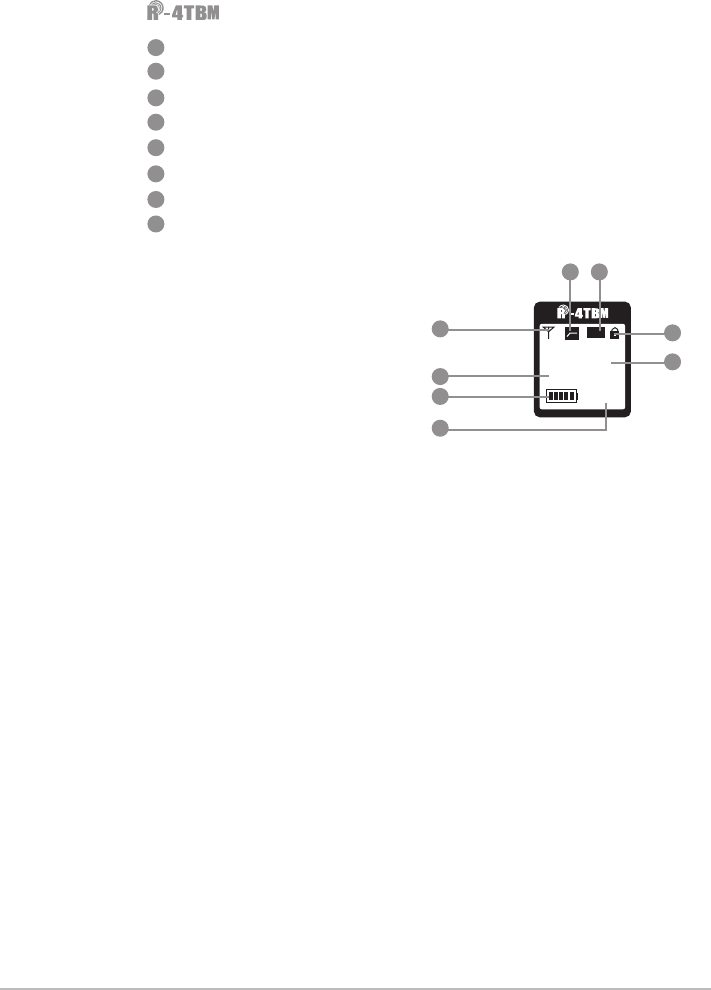
Transmission Power: Hi (High) and Lo (Low)
Indicate current Group and current Channel
Frequency: it shows the RF frequency
Battery level: in 5 levels
Sensitivity Value
Low Cut indication
Attenuate Indication
Lock On Statue
For screen display and operation please refer to ''6-5. System
operation setup for Body-Pack transmitter''.
-12dB
IDoff
633.875 MHz
G: 1 C: 11
AT
Hi
LCD displays
9
10
11
12
13
14 15
16
9
10
11
12
13
14
15
16
21
4-6 Accessories
Clip
4-pin mini XLR
Wind shield
4-7 Microphone Choices
Lavaliere microphone // CM-501 CM-201i CM-125i
Note: CM-501 is standard accessory.
CM-501 CM-201i CM-125i
SELF-MA N
SM-018
SELF-MA N
SM-006
AC power cable* 1
Cascading RF cable* 2
XLR(M)/XLR(F) Audio cable * 1
AC power cascading cable* 1
MH-56 Microphone Holder * 1
1
1
1
1 1
1
4
4
2
2
2
2
3
3
333
3
5
5
22
Headset microphone // CM-214i CM-214Ui CM-214ULi CM-235i CX-504
Gooseneck
Adjustable head ring
Head ring
4-pin mini XLR
Wind shield
CM-214i
CM-235i
CM-214Ui CM-214ULi
Standard:
4-pin mini XLR
3-pin mini XLR
3.5 stereo jack
CM-504
4
4
44
4
4
5
55 5
6
66
7
7
8
8
88
8
8
23
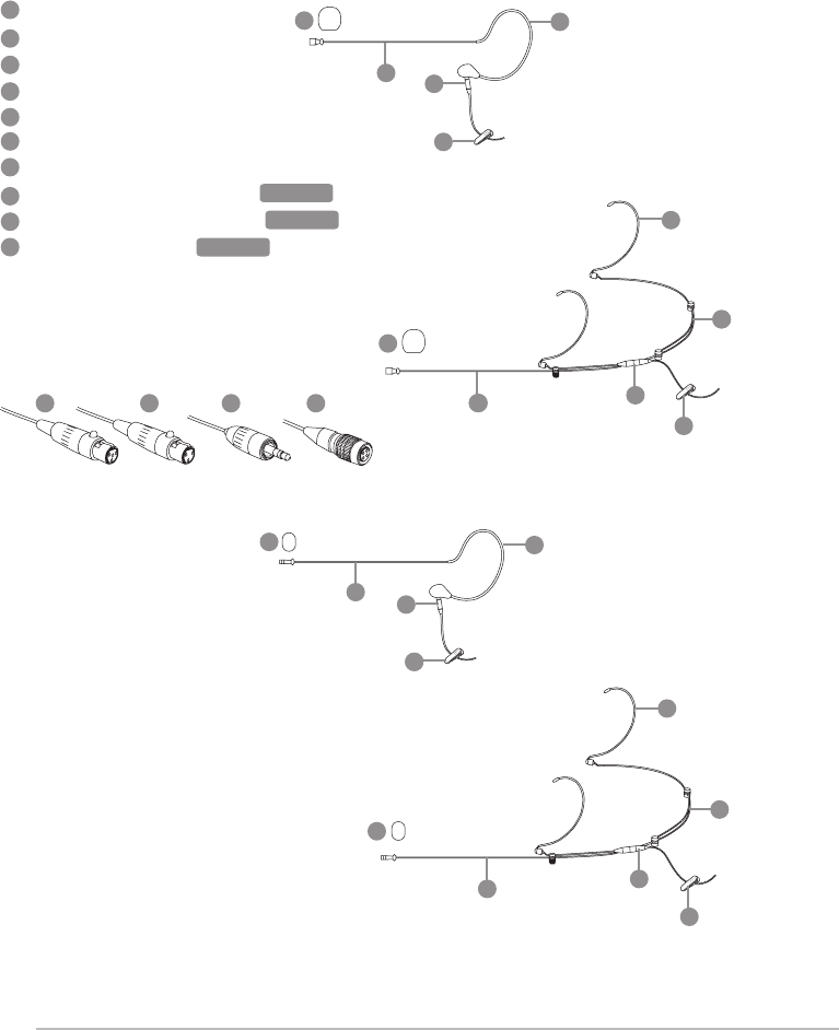
Ear-hook microphone // CM-801 CM-804i CM-8015 CM-825i
Boom
Adjustable Headband
Adjustable ear hook
Detachable cable
Clip
Windscreen
4-pin mini XLR
3-pin mini XLR optional
3.5 stereo jack optional
4-pin Hirose jack
optional
optional
optional
CM-801
CM-804i
CM-8015
CM-825i
124
2
9
9
9
9
9
5
10
10
10
18
18
11
11
11
11
11
12 12
12
12
12
13
13
13
13
13
14
14
14
14
14
15
15
16
16
17
17
24
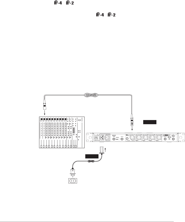
Amplier
AC power
cable
Wall socket
Audio output
Step 2
Step 1
5. Connection
5-1 Connecting the receiver
1.Connect the audio signal cable
Connect theR-4 / Raudio output to a mixer or an amplier:
Audio cable: one end of the XLR or φ6.3mm audio cable is connected
to the ''AF output balanced'' of / and the other to the audio
input of the mixer or amplier.
2.Connect the power
Connect AC power cable: insert one end to the receiver's AC jack and
the other to AC power outlet (100~240VAC).
圖 1
25
Cascading of AC power cable and antennas (for R-4 only)
Wall socket
More R-4s…
*Up to 10 units can be cascaded for power/antenna.

26
The mute switch of handheld transmitter also serves to turn the power
on. Therefore, the power will come on when the batteries are replaced.
Place the mute switch at mute if you do not want to turn the power on
immediately after battery replaced.
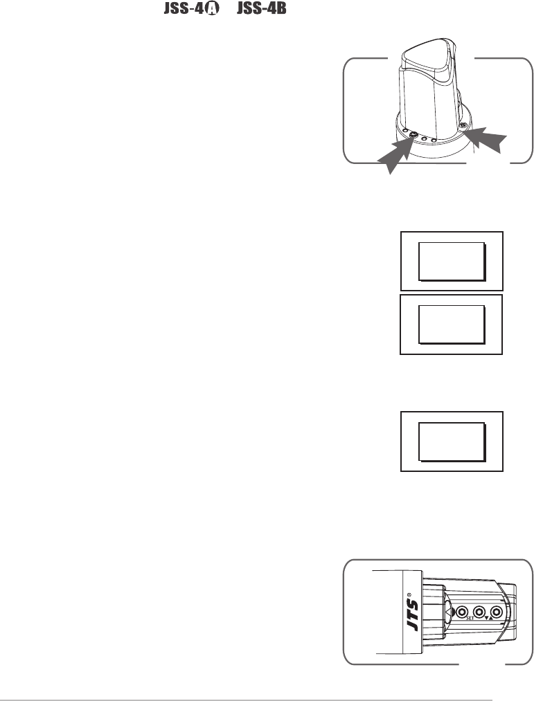
1.Unscrew the outer tube of the transmitter.(Figure1)
2.Place 2 AA batteries in the battery compartment according to their
polarity.(Figure 2)
3. Screw the outer tube back on.(Figure 3)
4. To turn the transmitter on:
a. Push Power ON/OFF to turn on. (Figure 4a)
b. Or, turn the power on by switching the MUTE switch up.(Figure 4b)
5. Dene the transmitter parameters according to the instructions.
Figure 1 Figure 2 Figure 3 Figure 4a Figure4b
5-2 Installing transmitter // /
27
Figure1 Figure2 Figure3 Figure4 Figure5
1. Slide the battery cover open as indicated by the arrow. (Figure 1)
2. Place 2 AA batteries in the battery compartment according to their
polarity.(Figure2)
3. Slide the battery cover back on.(Figure3)
4. Depending on the type of microphone, insert the 4-pin mini XLR into
MIC IN to nish the installation.(Figure4)
5. Push Power ON/OFF to turn on. (Figure5)
6. Dene the transmitter parameters according to the instructions.
1. Unscrew the outer tube of the transmitter.(Figure 1)
2. Place 2 AA batteries in the battery compartment according to their
polarities.(Figure 2)
3. Screw the outer tube back on.(Figure 3)
4. Turn the transmitter on.(Figure 4)
5.Dene the transmitter parameters according to the instructions.
Figure 1 Figure 2 Figure 3
Figure 4
5-3 Installing transmitter // /
5-4 Installing transmitter //
28
-1
I
633.875
G: 1 C
UF-20TB
Hi
Figure1 Figure2 Figure3
Figure4 Figure5
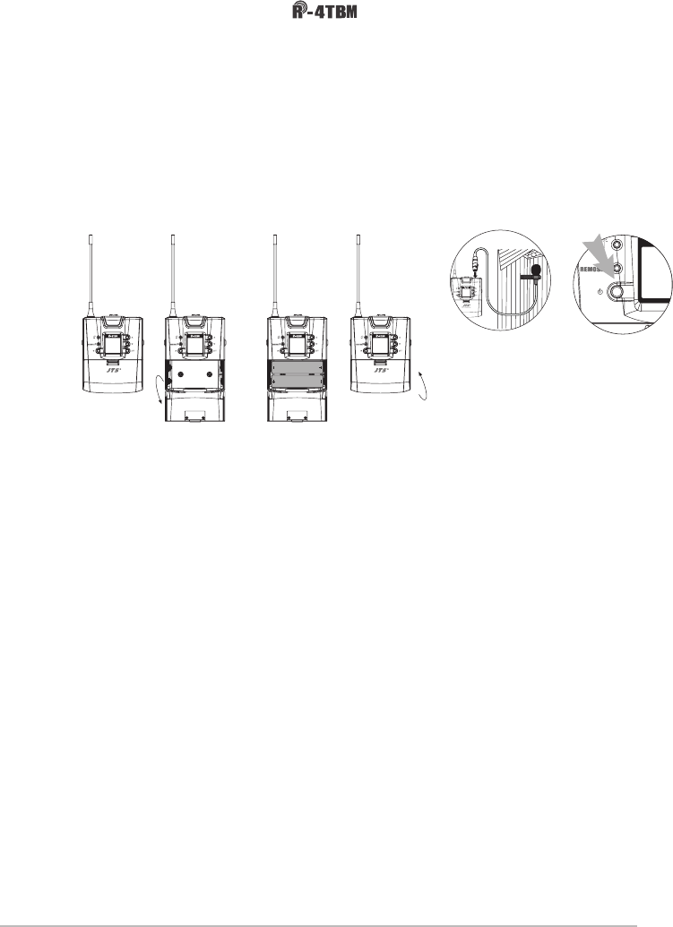
1. Open the battery cover as indicated by the arrow. (Figure 1)
2. Place 2 AA batteries in the battery compartment according to their
polarity.(Figure2)
3. Close the battery cover back on.(Figure3)
4. Depending on the type of microphone, insert the 4-pin mini XLR into
MIC IN to nish the installation.(Figure4)
5. Push Power ON/OFF to turn on. (Figure5)
6. Dene the transmitter parameters according to the instructions.
5-5 Installing transmitter //
UHF PLL Transmitter
-12dB
IDoff
633.875 MHz
G: 1 C: 11
UF-20TB
AT
Hi
-12dB
IDoff
633.875 MHz
G: 1 C: 11
UF-20TB
AT
Hi
-12dB
IDoff
633.875 MHz
G: 1 C: 11
UF-20TB
AT
Hi
UHF PLL Transmitter
-12dB
IDoff
633.875 MHz
G: 1 C: 11
UF-20TB
AT
Hi
29
6. Operation
Push and hold ''SET'' for 2 seconds to enter the setting mode. Turn
the rotary switch to select the desired item. Push the rotary switch
(or SETUP) to enter the setting page. Spin the switch to select the
desired value or function. Push SETUP to save the settings. Push EXIT
to return to the previous page.
Parameter settings
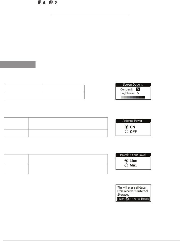
System Settings
◎Display
◎Mixed output level
◎Antenna power supply
◎Reset to factory defaults
◎Return
Push and hold SETUP for 2 seconds and the system is
reset to factory defaults and restarts.
Return: push SETUP to return to the previous page.
Contrast 0~9 (default: 5)
Brightness 0~9 (default: 5)
OFF(Line) Line output is selected for balanced
mixing output level.
ON(Mic) Mic output is selected for balanced
mixing output level.
ON (DC12V/100mA is provided to) power
the external antenna booster.
OFF
6-1 Operation // /
30
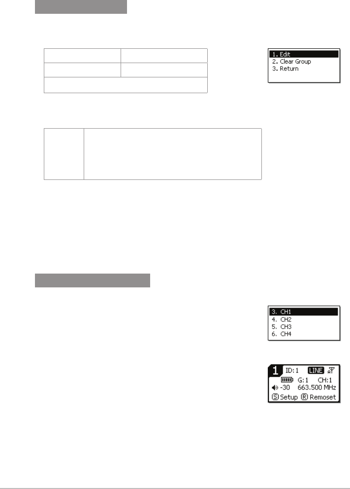
Self-dened groups
Dene receiver channel
◎Edit a self-dened group
1.Push and hold SETUP for 2 seconds. Spin the
rotary switch to select the desired receiver
channel in the main menu. Push the switch to
start dening.
or
2.Push SEL of the receiver channel to be dened.
Push and hold SETUP for 2 seconds to start
dening.
◎Return
Return: push SETUP to return to the previous page.
G U1~U6 (group no.)
CH 1~24 (channel)
---.---MHz (frequency setting)
◎Delete a self-dened group
Group Select the group to be deleted
from U1~U6, push SETUP and the
program will ask if you want to de-
lete the group. Push ''Yes'' to delete.
31
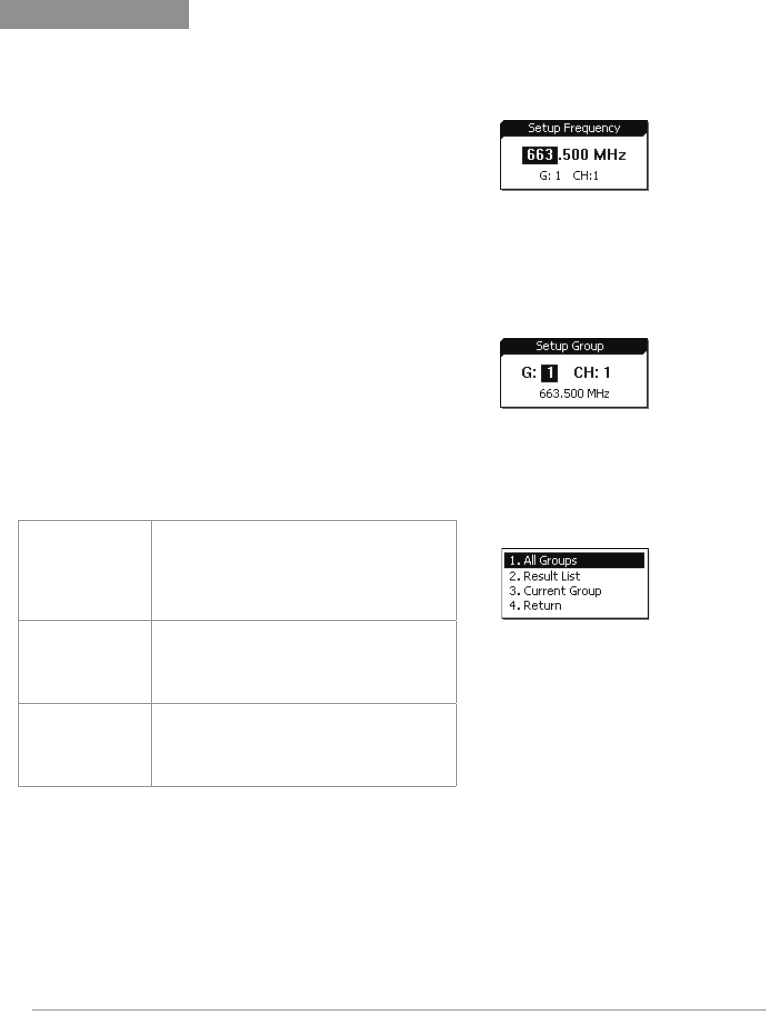
Receiver channel 1
◎Frequency setting
◎Default group
Spin the rotary switch to select group ''G:'' through 1
to 6: Push the switch to conrm the selection.
Spin the rotary switch again to select channel
''CH:'' up to 22 channels are available. Push SETUP
to conrm and save the selection.
Select the left 3 digits of the frequency; spin the
rotary switch to adjust in the increment of ''+/-'' 1
MHz. Push the switch to conrm the selection.
Select the right 3 digits of the frequency; spin the
rotary switch to adjust in the increment of ''+/-''
0.025 MHz. Push SETUP to conrm and save the
selection.
◎Channel scan
Scan all
groups Push the rotary switch to start
scanning. The system goes to the
selection page once the scanning
is done. It is also possible to arrive at
here through menu.
Scan result Push the rotary switch to enter the
selection page and examine the
result. Select an available channel
and push SETUP to save the selection.
Scan current
group
The next group will be scanned every
time the rotary switch is pushed.
Make the selection and push SETUP
to save it.
32
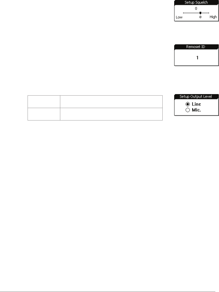
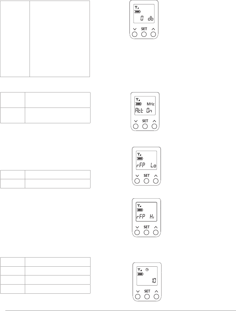
◎Squelch
◎Device ID
+15~ -5:the higher the value, the less sensitive
the receiving, and vice versa. The default is 0.
Device ID: 0~255: this setting affects the use of REMOSET;
both the receiver and transmitter must be on the same
Device ID before REMOSET is available.
Note: this does not apply when the
microphone Device ID is not activated.
◎Output Level
Line Line output is selected for channel 1
balanced output level.
Mic Mic output is selected for channel 1
balanced output level.
33
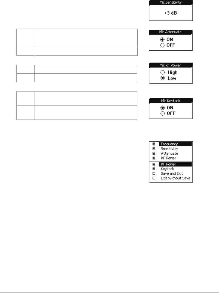
Sensitivity
Synchronization options
Input attenuation
RF power
Key lock
Adjustment range:-15dB~+15dB;the default is 0.
Use the rotary switch to search the items for REMOSET
and push the knob to select.
□ Frequency
□ Sensitivity
□ Input attenuation
□ RF power
□ Key lock
□ Save and exit
□ Exit without saving
Push SETUP to save the selection, or just select ''Save and Exit.''
*At least one of the above has to be selected.
◎Microphone options
ON Audio input attenuation by 20dB (depend-
ing on whether the transmitter has the
corresponding function)
OFF No attenuation (default)
HI High transmission power 50mW
LO Low transmission power 10mW (default)
Lock
ON
Microphone is in the Lock ON mode as
pairing is complete
Lock
OFF
Microphone is not locked as pairing is
complete
Return
Return: push SETUP to return to the previous page.
34
◎DigCode(digital anti-interference)
ON Digital code activated
OFF Digital code deactivated
◎Return
Exit setting
Return: push SETUP to return to the previous page.
Push SETUP to exit the setting page and return to the main page.
Receiver channel 2
Receiver channel 3
Receiver channel 4
◎See channel 1
◎See channel 1
◎See channel 1
Volume adjustment
Push▲/▼key at each channel to adjust the volume up or down.
Mute, -31dB ~ 0dB. The default is -10 dB.
35
Pairing for REMOSET
4.Pairing 4 microphones simultaneously: push REMOSET and the blue indicator starts
to ashing. On the display all 4 receiver channels show ''Synchronizing,'' indicating
that data are being transmitted to all 4 microphones.
1.REMOSET:push REMOSET and the blue indicator will start ashing, indicating that
the frequency data is being transmitted.
2.REMOSET successful:the blue indicator lights up on the transmitter for 3 seconds
and that on the receiver stops ashing.
3.REMOSET failed:if the blue indicator ashes slowly on the receiver, check that:
(1) The ''frequency range labels'' on ''both'' the receiver and transmitter are the
same;
(2)''Pairing'' in the function menu of the transmitter is ''activated;''
(3) The ''Device ID'' on the transmitter is the same as that on the receiver; and
(4) Transmitter battery is low (synchronization is impossible when battery is low).
*It should be avoided to have two or more receivers on REMOSET when REMOSET is used, as
sometimes it prevents pairing due to the mutual interference of REMOSET signals.
/
//
LED LED
36
5.Pairing a single microphone: push SEL of the receiver channel to be paired.
Push REMOSET and the blue indicator starts to ash. On the display the receiver
channel is ''Synchronizing,'' indicating that data is being transmitted to that
microphone.
Others
Push ''SEL'' below each of the channel volume keys:
Push SETUP to enter the page containing the selections of that channel for
parameter settings.
Push REMOSET to start pairing that channel; other channels remains
standing by.
37
6-2 Operation // /
Push and hold SET for 2 seconds to enter the
setting mode. Push SET repeatedly to locate
the desired item. Use▲/▼for parameter
settings. Push SET again to save the changes
and exit.
◎ FREQ: frequency setting
Increment of 1MHz Select with▲/▼
Increment of 0.025MHz Select with▲/▼
◎ GROUP: group/channel setting
G (group) Select default group1~6
CH (channel) Select default channel(s),
up to22
Sensitivity: for microphone input
Normal
sensitivity
GAIN:+15dB
GAIN:+12dB
GAIN:+9dB
GAIN :+6dB
GAIN:+3dB
GAIN:0dB(default)
GAIN:-3dB
GAIN:-6dB
GAIN:-9dB
GAIN:-12dB
GAIN:-15dB
Start with group number and then
channel number.
Start with those digits in 1MHz and
then those in 0.025MHz
The sensitivity is at GAIN 0dB (default)
as shown above.
38
ON Digital code activated
OFF Digital code
deactivated (The
receiver will be in mute
status if receiver has this
function activated.)
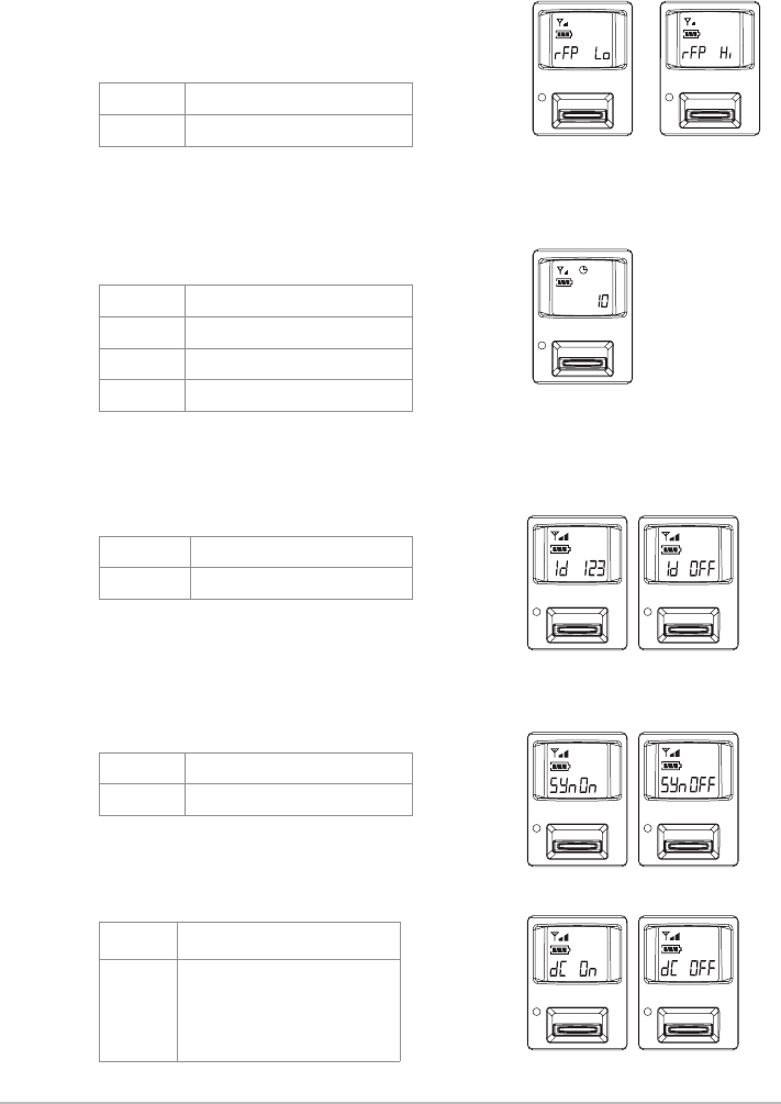
◎ RFP: RF power of microphone
rF Lo 10mW (default)
rF Hi 50mW
◎AUTO-OFF: time to turn off microphone
automatically (in MUTE)
OFF Deactivated
1 1 minute to auto off
10 10 minutes to auto off
30 30 minutes to auto off
RFP low RFP Hi
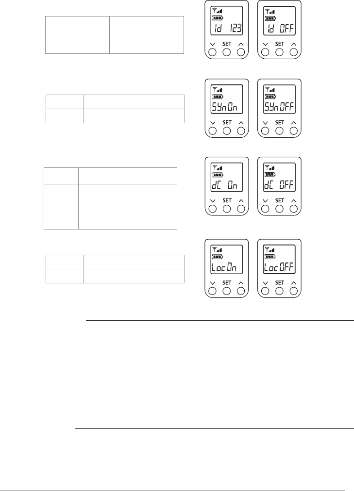
◎ Remoset (ON/OFF)
Syn on Remoset activated
Syn oFF Remoset deactivated
◎ Device ID
ID OFF Device ID deactivated
ID 0~255 Device ID 0 ~ 255
Note: default is 10 minutes.
◎Digital code (digital anti-interference)

39
Others
Indicator
Battery charging is supported. The transmitter turns off automatically when
charging.
When battery is < 1.8V, the transmitter will turn off automatically.
If the microphone is turned off with the mute switch on mute, just slide the
switch up to turn the microphone on.
Green: power is sufcient, > 2V
Green ashing: microphone mute
Red: power low, ≤ 2V
Red and green ashing alternately: microphone mute
and power low
Blue: on for 3 seconds, indicats pairing successfully
Blue ashing: data receiving error LED
40
6-3 Operation // /
6-3-1 Power ON/OFF
(1)Power on
To turn on: push Power ON/OFF once.
To turn off: push and hold Power
ON/OFF until the display
shows ''power off.''
Note: when the button is pushed and
held, ''mute on'' or ''mute off'' will
come out rst before ''power off.''
(2)Mute: when the transmitter is in use (the display is
at the main page)
To mute: Short push Power ON/OFF and the display
shows ''mute on.''
When in mute, the power indicator is ashing red
and the display shows mute on.
To unmute: Short push Power ON/OFF and the
display shows ''mute off.''
(3)Exit the setting menu
When in setting menu: push Power ON/OFF to
return to the main page.
When in function ''items'': push Power ON/OFF once
to return to the setting menu and again to the main
page.
**The display will show ''battery low'' when the
battery is low. In about 30 minutes, the transmitter
will turn itself off automatically.
6-3-2Menu function settings
Push and hold SET for 2 seconds to enter
the function setting menu.
(1)Push▲or▼to selected the desired item.
Push SET to show the default setting.
(2)When the default is shown, use▲or▼to
change the setting and then push SET to
save the change.
Figure 1
Figure 2
LED
Power
Mute On
Mute Off
Battery
Low
41
1.Frequency
(1) Use ▲ or ▼ to move to ''1. Frequency
setting.'' Push SET to enter the setting page.
(2) To adjust the rst 3 digits of the frequency, use
▲ or ▼ to adjust in the increment of '' +/- '' 1
MHz. Push SET to adjust the 3 digits on the right.
(3)To adjust the 3 digits on the right: use ▲ or ▼
to adjust in the increment of ''+/-'' 0.025 MHz.
Push SET to save the change and exit.
2.Group / Channel
(1)Use ▲ or ▼ to move to ''2. Group / Channel.''
Push SET to enter the setting page.
(2)Select the desired group with ▲ or ▼. Push SET
to save and to the channel settings.
(3)Select the desired channel with ▲ or ▼. Push
SET to save the change.
Frequency
Group / Channel
Sensitivity
Group / Channel
Group / Channel
Frequency
Group / Channel
Sensitivity
Frequency
Frequency
42
3.Sensitivity
(1)Use ▲ or ▼ to move to ''3. Sensitivity.''
Push SET to enter the setting page.
(2)Adjust the sensitivity with ▲ or ▼ in the
increment of 3 dB. Save the change by
pushing SET. The sensitivity ranges from -15dB
to +15dB.
4.Low Cut
Use ▲ or ▼ to move to ''4. Low Cut''
Push SET to enter the setting page.
Push ▲ to deactivate Low Cut function.
Push ▼ to activate Low Cut function.
Push SET to save the change.
Frequency
Group / Channel
Sensitivity
Group / Channel
Sensitivity
Low Cut
Off
On
Low Cut
Low Cut
Sensitivity
43
5.Device ID
(1)Use ▲ or ▼ to move to ''5. Device ID.'' Push SET
to enter the setting page.
Setting page
(2)Use ▲ or ▼ to select the Device ID between 0
and 255. Push SET to conrm the selection and
go to Device ID on/off.
Push ▲ to activate. The microphone has to be
on the same Device ID with the receiver in
order for REMOSET to work.
Push ▼ to deactivate. The microphone will
receive the REMOSET data from any receiver
with REMOSET function regardless its Device ID.
Push SET to save the change.
6.Remoset
Use ▲ or ▼ to move to ''6. Remoset.''
Push SET to enter the setting page.
Push ▲ to activate. Remoset is activated.
Push ▼ to deactivate. Remoset is deactivated,
but the microphone is more energy efcient this
way. When pairing is not needed, it is
recommended to deactivate it to extend the
battery power.
Push SET to save the change.
Device ID
Remoset
RF Power
Device ID
Remoset
RF Power
Remoset
Device ID
Device ID
Off
On
Off
On
44
7.RF Power:
Use ▲ or ▼ to move to ''7. RF Power.''
Push SET to enter the setting page.
Push ▲: high→ high RF power
Push ▼: low→ low RF power
Push SET to save the change.
Note: The microphone drains more power out of
battery with high RF power.
8.Contrast:
(1)Use ▲ or ▼ to move to ''8. Contrast.'' Push SET
to enter the setting page.
(2)Adjust the contrast using ▲ or ▼. The larger
the value, the dark it is, and vice versa. The
contrast ranges from 0 to 20.
9.Light time
(1)Use ▲ or ▼ to move to ''9. Light time.'' Push SET
to enter the setting page.
(2)Adjust the time using ▲ or ▼.
Available for selection: off, 5~30 sec
(increment of 5 seconds), always on.
Device ID
Remoset
RF Power
Contrast
Light time
DigiCode
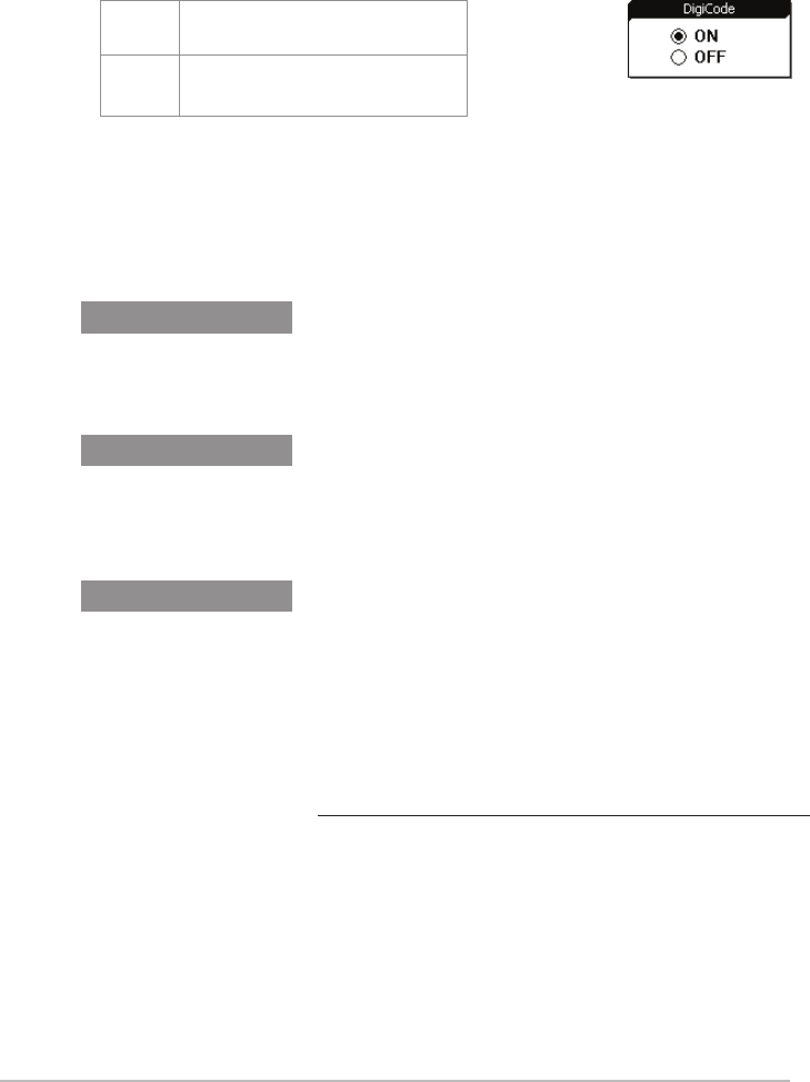
Contrast
Light time
DigiCode
Light time
LCD contrast
RF Power
High
Low
sec
45
10.Digicode
Use ▲ or ▼ to move to ''a. DigiCode.''
Push SET to enter the setting page.
Push ▲ to activate. The microphone will transmit
digital code signals.
Push ▼ to deactivate. The microphone will not
transmit digital code signals. The receiver will be
in mute status if receiver has this function
activated.
11.Reset
Use ▲ or ▼ to move to ''b. Reset.'' Push SET to
enter the setting page.
Push ▲ to conrm and the handheld transmitter
will be reset.
Push ▼ to cancel the reset.
Push SET to save the change.
12.KeyLock
Use ▲ or ▼ to move to ''c. KeyLock.''
Push SET to enter the setting page.
(1)Push ▲: all keys will be locked to prevent
accidental triggering of any button.
Push SET to save the change.
Push ▼ to ''unlock'' and the key lock is
deactivated.
Push SET to save the change.
(2)Unlock: when the display is in the main page,
push and hold SET for 2 seconds to go to the
key lock page. Push ▼ to unlock.
Push SET to save the change.
13.Exit
Use ▲ or ▼ to move to ''d. Exit.'' Push SET to
return to the main page.
DigiCode
Reset
KeyLock
DigiCode
Reset
KeyLock
This will erase all date from
Mic Internal Storage.
DigiCode
Reset
KeyLock
Reset
KeyLock
Exit
KeyLock
ON
OFF
Yes / No
46
Push and hold SET for 2 seconds to enter the
setting mode. Push SET repeatedly to select
the desired item. Use ▲ / ▼ for parameter
settings. Push SET again to save the change
and exit.
Parameter settings
◎ FREQ: Frequency setting
Increment of 1MHz Select
with▲/▼
Increment of 0.025MHz Select
with▲/▼
◎ GROUP: group/channel setting
G (group) Select default group 1~6
CH (channel) Select default channel(s),
up to 22
6-4 Operation //
Start with group number and then channel
number.
Start with those digits in 1MHz and then
those in 0.025MHz
47
◎ ATT: Microphone input attenuation
At oFF No attenuation for
audio input
At on 20dB attenuation for
audio input
Sensitivity: microphone input sensitivity
Normal
sensitivity
GAIN:+15dB
GAIN:+12dB
GAIN:+9dB
GAIN :+6dB
GAIN:+3dB
GAIN:0dB
GAIN:-3dB
GAIN:-6dB
GAIN:-9dB
GAIN:-12dB
GAIN:-15dB
The sensitivity is at GAIN 0dB (default)
as shown above.
◎ RFP: RF power of the transmitter
rF Lo 10mW(default)
rF Hi 50mW
Two output levels can be chosen
(as per local regulation)
RFP low
RFP Hi
The audio input attenuation is
20dB as shown above.
◎AUTO-OFF: time to turn off microphone automatically (in Mute status)
OFF Deactivated
1 1 minute to auto off
10 10 minutes to auto off
30 30 minutes to auto off
Note: default is 10 minutes.
48
◎DigiCode (digital anti-interference)
Others
Indicator
Battery charging is supported. The transmitter turns off automatically when
charging.
When battery is < 1.8V, the transmitter will turn off automatically.
Green: power is sufcient, > 2V
Green ashing: microphone mute
Red: power low, ≤ 2V
Red and green ashing alternately: microphone mute and power low
Blue: on for 3 seconds, indicats pairing successfully
Blue ashing: data receiving error
◎ Remoset (ON/OFF)
◎ Key lock
Syn on Remoset activated
Syn oFF Remoset deactivated
Loc on Lock ON
Loc oFF Lock OFF
◎ Device ID
ID OFF Device ID
deactivated
ID 0~255 Device ID 0 ~ 255
ON Digital code activated
OFF Digital code
deactivated (The
receiver will be in mute
status if receiver has this
function activated.)
49
6-5 Body-pack transmitter system operation setting //
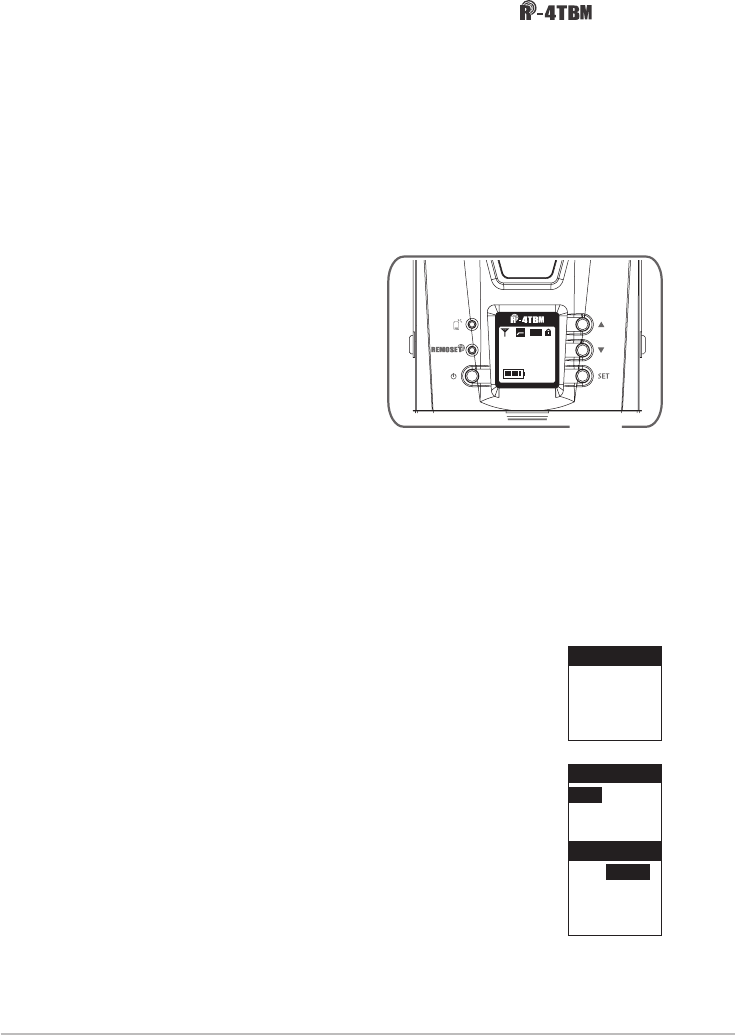
6-5-1 To turn on R-4TBM body-pack transmitter (Fig.1)
(1) To turn on the power: press the Power button.
(2) To turn off the power: press the Power button for a while. The
screen will display “Power OFF” after approx. 2 seconds. The
body-pack transmitter will be turned off.
(3) To exit the function setting menu: when you are at the func-
tion setting menu, press Power button to go back to the main
screen.
6-5-2 Function setting menu:
Press SET for a while. After two seconds, it will go into
the function setting menu.
(1) Press ▲、▼ and select the desired item. Press SET
to enter into the menu.
(2) After entering into the menu, press ▲、▼ to ad-
just the values. Press SET to save the setting.
1. Frequency: set the frequency
(1) Press ▲、▼ to frequency setting. Press SET to
enter into the frequency setting screen.
(2) When entering into the frequency adjustment
screen, adjust the rst three digits of frequency at
the left. Press ▲、▼ using “+/-“ with 1MHz as the
unit of modication. After adjustment, press SET to
adjust the three frequency at the right.
(3) Adjust the three digits of frequency at the right:
Press ▲、▼ using “+/-“ with 0.025MHz as the unit
of modication. After the adjustment, press SET to
save the setting.
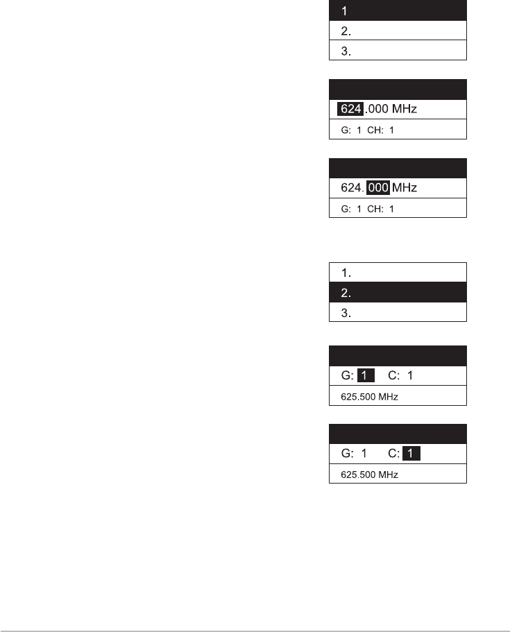
Fig. 1
Frequency
624 .750
G: 1 C: 1
Frequency
624. 750
G: 1 C: 1
Frequency
Group/Chan
Sensitivity
Attenuate
Low Cut
-12dB
IDoff
633.875 MHz
G: 1 C: 11
AT
Hi
50
2. Group / Channel
(1) Press ▲、▼ to select “2. Group / Channel.”Press
SET to enter into the setting screen.
(2) After entering into the screen, press ▲、▼ to select
desire Group. Press SET for saving and change into the
channel setting.
(3) Press ▲、▼ to select desire channel. Press SET to
save the setting.
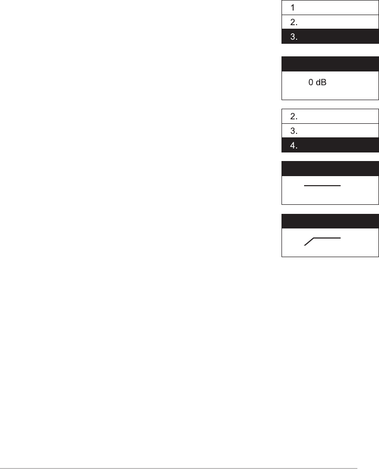
3. Sensitivity
(1) Press ▲、▼ to “Sensitivity.”Press SET to enter into
the “Sensitivity”setting screen.
(2) Press ▲、▼ to adjust the sensitivity. Use 1 dB as unit
of modication. After adjustment, press SET to save the
setting; the range of sensitivity is -15dB~+15dB.
4. Attenuate
(1) Press ▲、▼ to enter into “Attenuate.” Press SET
to enter into the “Attenuate” setting screen.
(2) Press ▲to turn on
(3) Press ▼ to turn off
After adjustment, press SET to save the setting.
Group/Chan
G: 1
C: 1
624.750MHz
Group/Chan
G: 1
C: 1
624.750MHz
Sensitivity
0 dB
Sensitivity
-3 dB
Attenuate
ON
OFF
Attenuate
ON
OFF
Frequency
Group/Chan
Sensitivity
Attenuate
Low Cut
Frequency
Group/Chan
Sensitivity
Attenuate
Low Cut
Frequency
Group/Chan
Sensitivity
Attenuate
Low Cut
51
5. Low Cut
(1) Press ▲、▼ to select“Low Cut.” Press SET to enter
into the “Low Cut” setting screen.
(2) Press ▲ to turn on the Low Cut function.
(3) Press ▼ to turn off the Low Cut function.
6. Device ID: to set the Device ID
(1) Press ▲、▼ to set the ID. Press SET to enter into
“Device ID” setting screen.
(2) Press ▲、▼ to adjust the pre-set ID value. The
range is from 0 ~ 255. After the adjustment, press SET to
go to ID setting: On / Off
ID: On → The ID of the microphone and the ID of the
receiver shall be the same as to use the REMOSET
function.
ID: OFF → Ignore the ID value. The microphone
will receive all REMOSET information transmitted
by“receivers with ID code”
Press SET for setting.
This setting will affect the usage of REMOSET.
Frequency
Group/Chan
Sensitivity
Attenuate
Low Cut
Low Cut
OFF
Low Cut
ON
Device ID
Remoset
RF Power
Contrast
Light Time
Device ID
1
ID : ON
Device ID
1
OFF / ON
52
7. Remoset: to turn on/off the REMOSET
(1) Press ▲、▼ to select REMOSET function. Press SET to
enter into “Remoset” setting screen.
(2) Press ▲: to turn on and REMOSET function can be
used.
(3) Press ▼: to turn off. REMOSET function cannot be
used. The microphone will be more power-saving.
When not using REMOSET function, it can prolong the
usage time of the battery when it is “OFF.”
8. RF Power: setting of RF power
(1) Press ▲、▼ to select RF power. Press SET to enter
into “RF Power” screen for RF power setting.
(2) Press ▲: High → High RF power
(3) Press ▼: Low → Low RF power.
Press SET to save the setting.
Note: When It is in “High RF power”, the power
consumption of the microphone is larger which would
shorten the usage time of the battery.
9. Contrast: adjustment of screen contrast
(1) Press ▲、▼ to select“Contrast.” Press SET to enter
“Contrast” screen for contrast adjustment.
(2) Press ▲、▼ to adjust the contrast. The higher the
value, the darker the color; on the contrary, it would
be lighter. There is a total of 0~20, 21 level of adjust-
ment.
Remoset
ON
OFF
Remoset
ON
OFF
RF Power
High
Low
RF Power
High
Low
Contrast
10
Device ID
Remoset
RF Power
Contrast
Light Time
Device ID
Remoset
RF Power
Contrast
Light Time
Device ID
Remoset
RF Power
Contrast
Light Time
53
10. Light Time: the the backlight time
(1) Press ▲、▼ to select backlight time. Press SET to
enter into “Light Time” screen.
(2) Press ▲、▼ to select the backlight time; you can
select “closed”, “5~30 seconds”(having 5 seconds
as the unit of change) or “constant light.”
The longer the backlight time, the shorter the usage
time of the battery.
11.Digicode
Use ▲ or ▼ to move to ''DigiCode.''
Push SET to enter the setting page.
Push ▲ to activate. The microphone will transmit
digital code signals.
Push ▼ to deactivate. The microphone will not
transmit digital code signals. The receiver will be
in mute status if receiver has this function
activated.
12. Reset
(1) Press ▲、▼ to select reset. Press SET to enter into
“Reset” screen.
(2) Press ▲to select conrm as to reset the internal
information of the handheld transmitter. Press SET to
save the setting.
(3) Press ▼to select cancel as to cancel the reset set-
ting. Press SET to save the setting.
Light Time
10 Sec.
Reset
KeyLock
Exit
Reset
KeyLock
Exit
All stored
data will be
erased.
Yes / NO
Device ID
Remoset
RF Power
Contrast
Light Time
DigiCode
DigiCode
54
13. Key Lock: setting of the keypad lock
(1) Press ▲、▼ to the keypad lock. Press SET to enter
into “key Lock” screen for keypad lock setting.
(2) Press ▲、▼ to select lock “ALL” , “Set & Power”
only or lock “OFF”. Press SET to save the setting.
ALL: All the buttons are locked as to prevent any
misoperation touch.(include Mute switch)
Set & Power: Only funtion buttons are locked, Mute
switch will not be locked.
(3) Press ▲、▼ to select lock off. Press SET to save the
setting.
(4) To unlock: press SET for two seconds and it will
directly go into the key lock screen. Press ▼to select
OFF. Press SET to save the setting.
14. Exit
Press ▲、▼ to select exit setting. Press SET to go back
to the main screen.
Reset
KeyLock
Exit
Reset
KeyLock
Exit
Press Set
for 2 Sec.
to unlock
keypad.
KeyLock
ALL
Set & Power
OFF
KeyLock
ALL
Set & Power
OFF
KeyLock
ALL
Set & Power
OFF
DigiCode
DigiCode

55
7. Digital Code Alert Function
When receiver's DigiCode function is OFF, the alert screen will
blink rapidly under these circumstance:
When receiver's DigiCode function is ON, the alert screen will
blink slowly under these circumstance:
2.When microphone's power is OFF.
3.When microphone's battery level is too low.
1.When microphone is under mute mode or microphone's
DigiCode function is OFF.
2.When microphone's power is OFF.
3.When microphone's battery level is too low.
1.When microphone is under mute mode.

56
8. Notes for the product
(1)For the optimized reception, keep the receiver 3m or more away
from the transmitter.
(2)Receivers and transmitters shall be kept at least 50cm away from
any metal object.
(3)Do not point the receiver directly into a speaker or there will be
annoying feedback noises.
(4)It is recommended to hold the transmitter (microphone) at the
middle section for the optimized audio pickup.
(5)In case that the microphone is not used for an extended period of
time, it is recommended to remove the batteries from the battery
bay in order to prevent electrolyte leaks from damaging the
transmitter.
(6)When changing the batteries, it is recommended to change both
batteries of the same manufacturer for the optimized power perfor
mance.

FCC Statement
Notice:
The changes or modifications not expressly approved by the party responsible for compliance
could void the user’s authority to operate the equipment.
This device complies with part 15 of the FCC Rules. Operation is subject to the following two
conditions: (1) This device may not cause harmful interference, and (2) this device must
accept any interference received, including interference that may cause undesired operation.
IMPORTANT NOTE:
To comply with the FCC RF exposure compliance requirements, no change to the antenna or
the device is permitted. Any change to the antenna or the device could result in the device
exceeding the RF exposure requirements and void user’s authority to operate the device.
FCC INFORMATION
The equipment has been tested and found to comply with the limits for a Class B
Digital Device, pursuant to part 15 of the FCC Rules. These limits are designed to provide
reasonable protection against harmful interference in a residential installation. This
equipment generates, uses and can radiate radio frequency energy and, if not installed and
used in accordance with the instruction, may cause harmful interference to radio
communication. However, there is no grantee that interference will not occur in a particular
installation. If this equipment dose cause harmful interference to radio or television
reception, which can be determined by turning the equipment off and on , the user is
encouraged to try to correct the interference by one or more of the following measures:
--Reorient or relocate the receiving antenna.
--Increase the separation between the equipment and receiver.
--Connect the equipment into an outlet on a circuit different from that to which the receiver
is connected.
--Consult the dealer or an experienced radio/TV technician for help.