JTS Professional Co R-4TB UHF PLL Body-Pack Transmitter User Manual
JTS Professional Co Ltd UHF PLL Body-Pack Transmitter
UserManual.wiki
>
JTS Professional Co
>
R-4TB User Manual
>
User Manual
Contents
1.
User Manual
2.
FCC Notice Info
User Manual
Navigation menu
Upload a User Manual
Namespaces
Wiki Guide
HTML
PDF
Info
Views
User Manual
Discussion / Help
Navigation
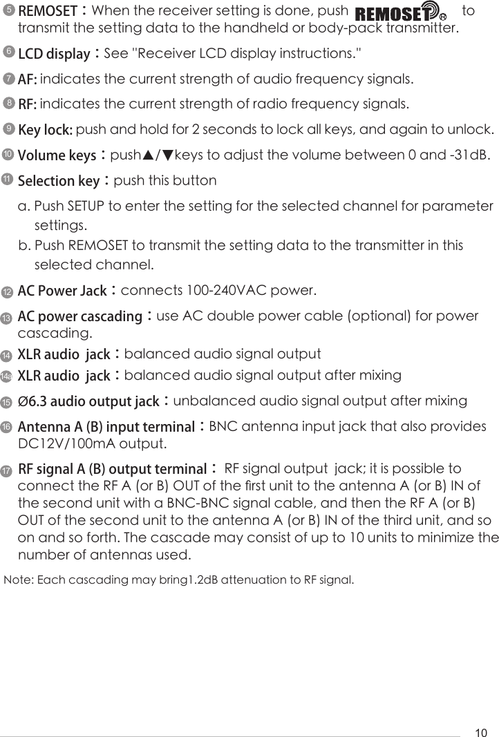
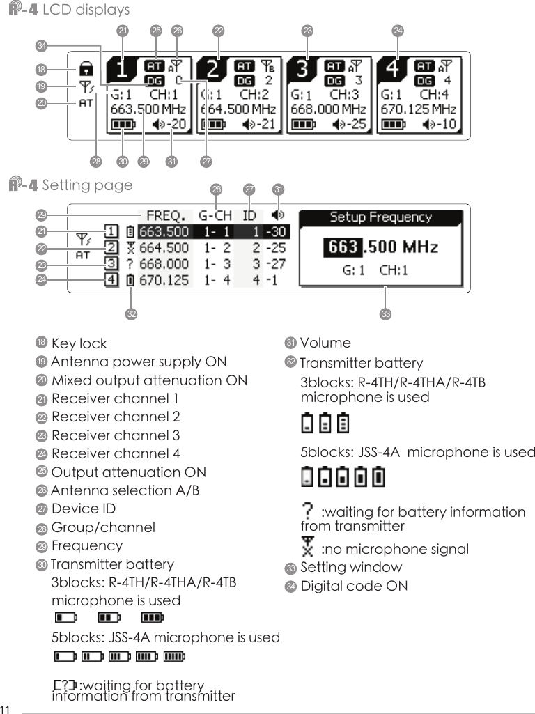
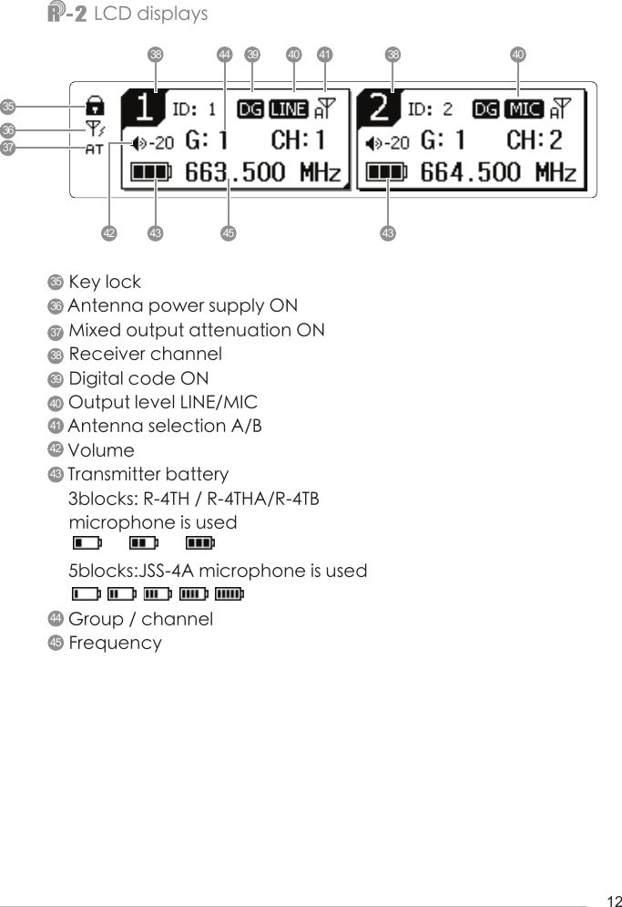
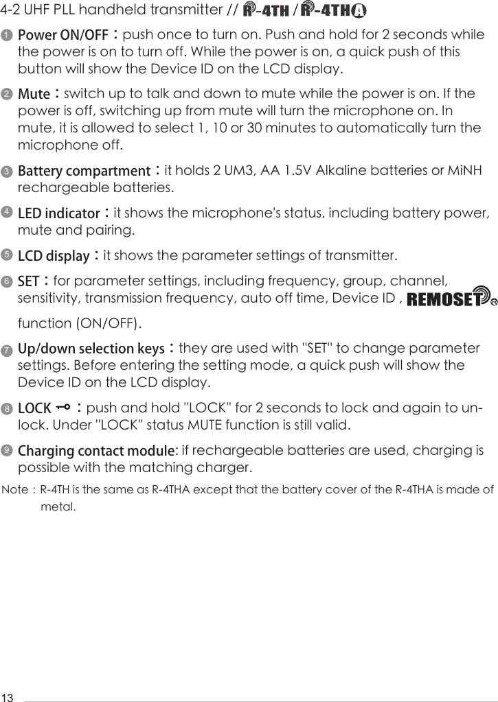
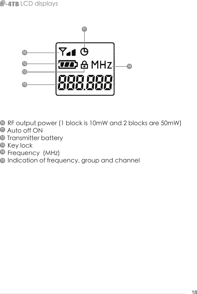
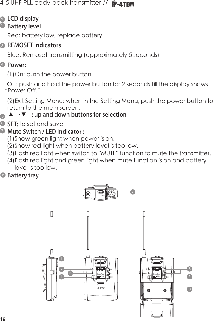
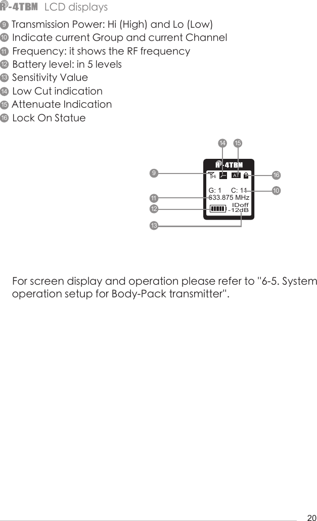
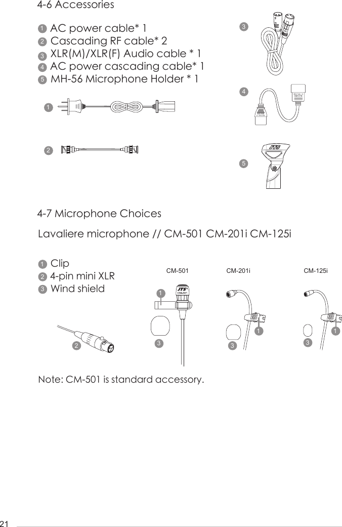
![94. Parts1423Power ON/OFF:ON:push once to turn on OFF:push and hold until ''Power OFF'' is shown on the LCD to turn off.EXIT:Push exit to cancel a selection or exit from the current menu when R-4/2 is in the ''setting menu.''Rotary Switch:when in the ''function menu,'' turn the switch to select the desired function; push the switch (or SETUP) to enter the selection and spin the switch to select the setting. Push [SETUP] to save the setting.SETUP:Push and hold for 2 seconds to enter the vsetting menu.'' Push SETUP to save the setting once the selection and setting are made according to ''3. Rotary Switch.''Front panelRear panel99111111332255774488664-1 UHF PLL 4-channel diversity receiver // 1010Front panelUHF PLL 2-channel diversity receiver // 1416 1617 1715 14a1312](https://usermanual.wiki/JTS-Professional-Co/R-4TB.User-Manual/User-Guide-3668733-Page-13.png)