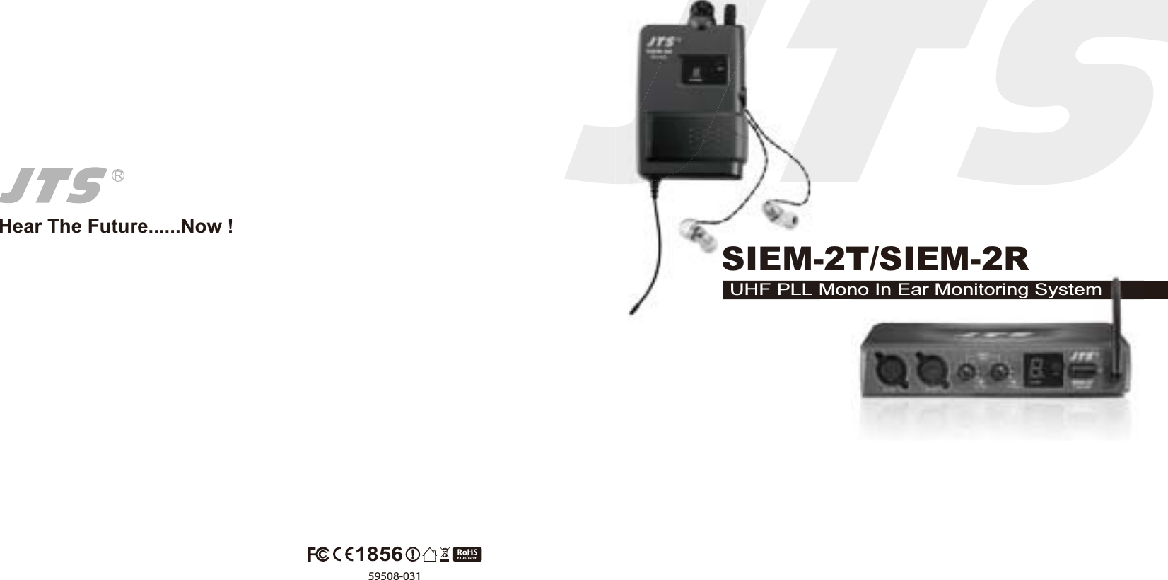
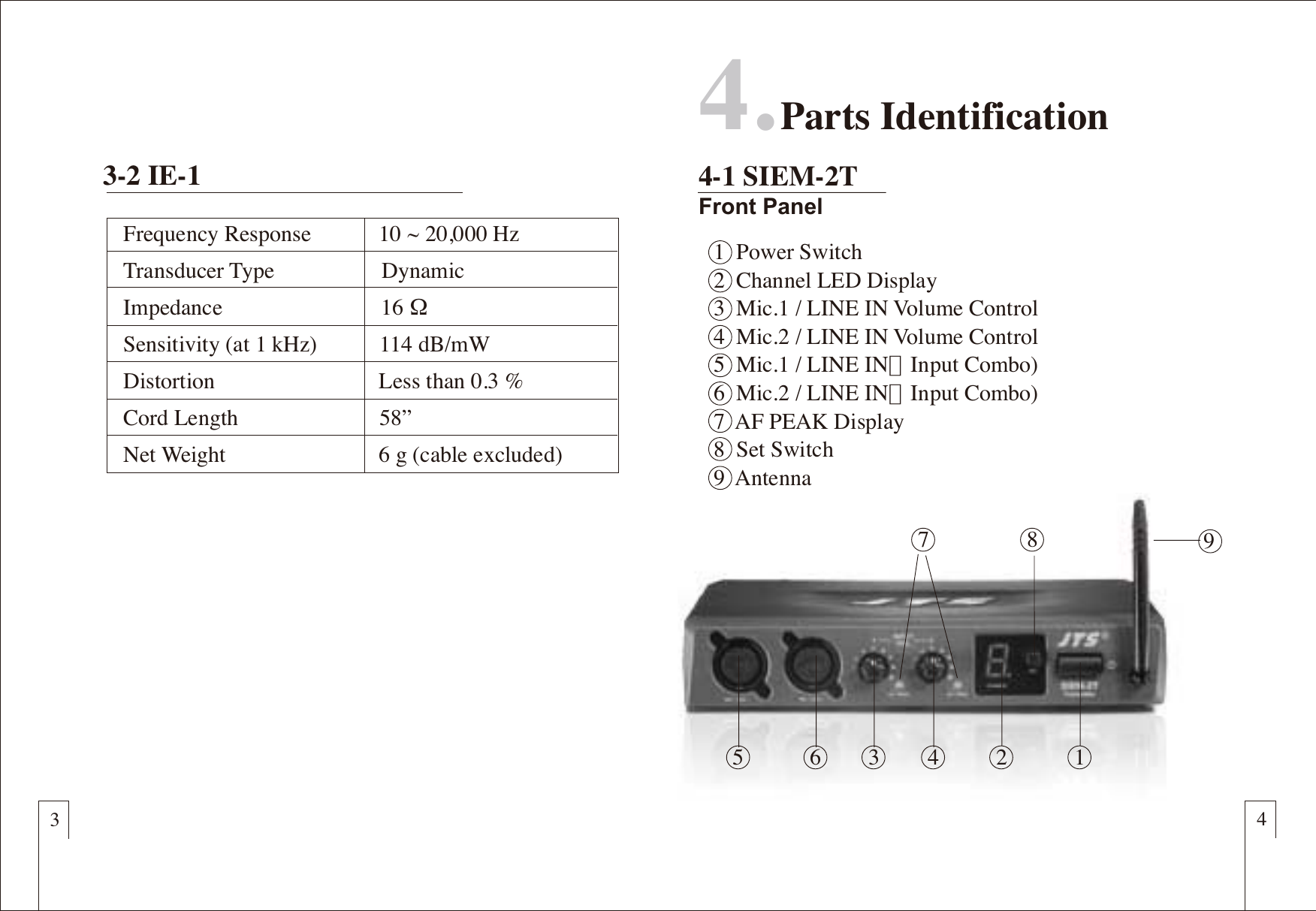
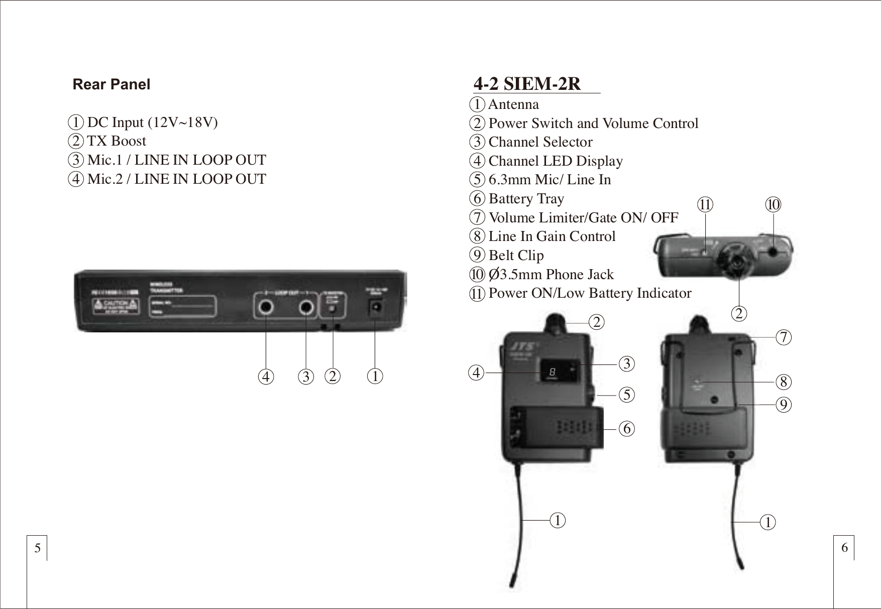
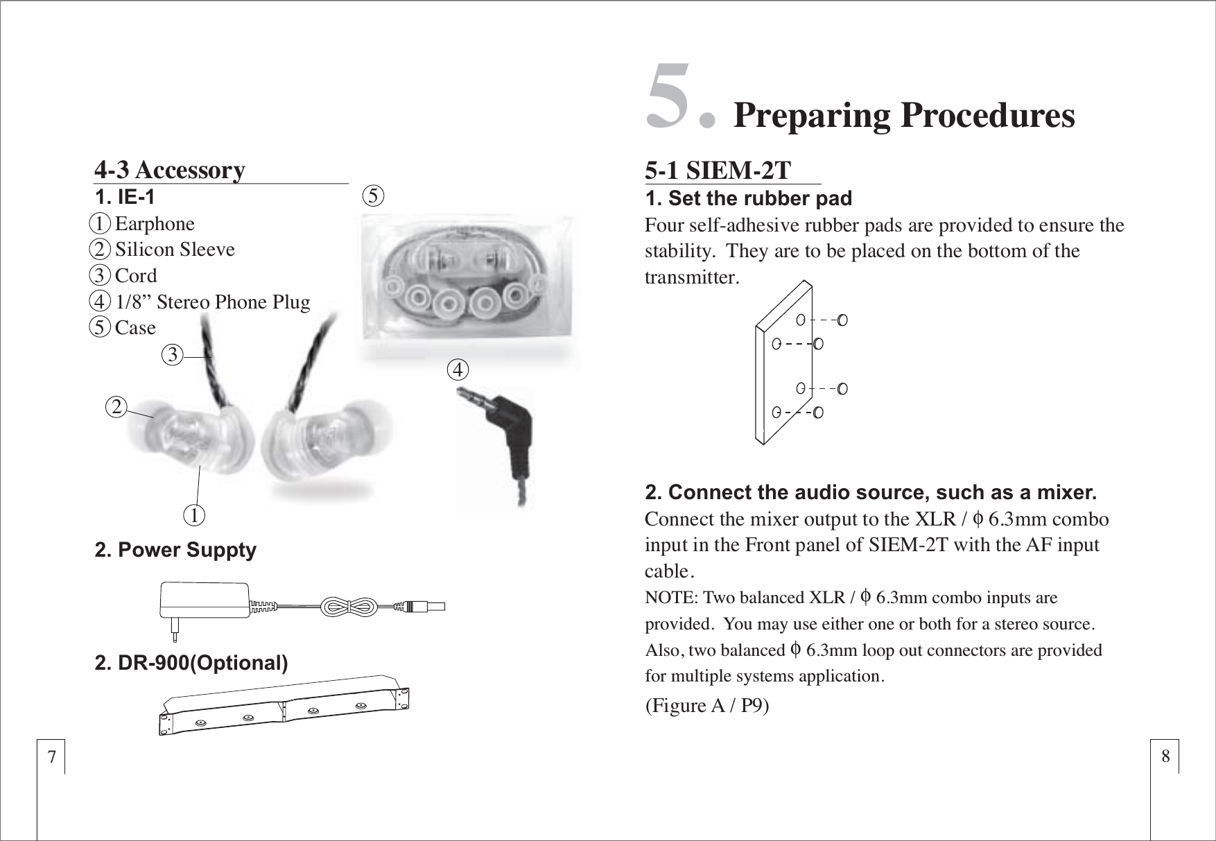
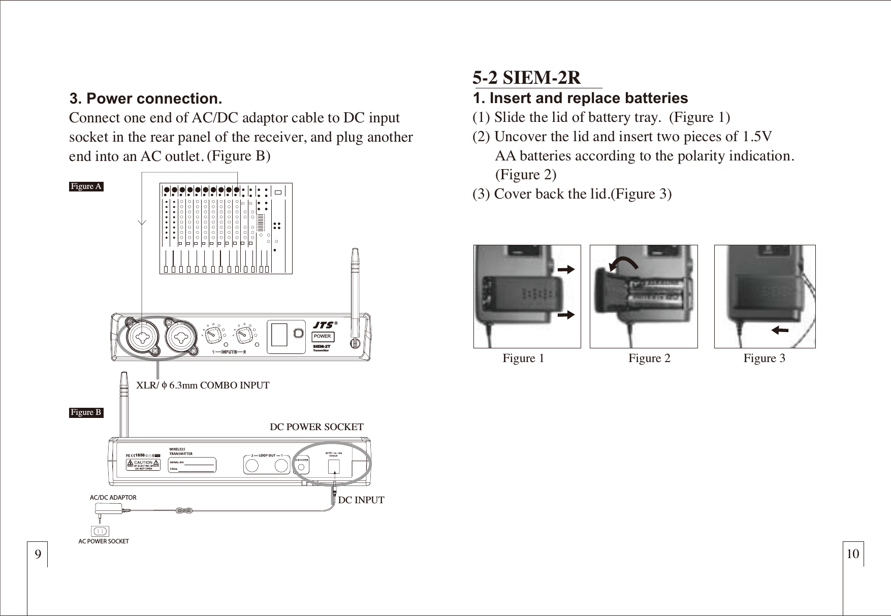
JTS Professional Co SIEM-2T UHF PLL Mono In Ear Monitoring System (Transmitter) User Manual

JTS Professional Co Ltd UHF PLL Mono In Ear Monitoring System (Transmitter)

User Manual

Hear The Future......Now !SIEM-2T/SIEM-2RUHF PLL Mono In Ear Monitoring System59508-0311856no In Ear Monitoring SystemSIEM-UHF PLL M
ATTENTIONPlease pay high attention to the following information.Sound Level (dB) Duration per day (hrs)The guideline published by Occupational Safety Health Administration (OSHA) in United States indicatesoverload volume level for prolonged listening may harm your hearing. Here below are referenced dataon maximum time exposure to sound level before hearing injury occurs.90929597100102105110115864321.510.50.25140 Avoid or injury may occur
TABLE OF CONTENTS1. Important Cautions2. Features3. Specification3-1 SIEM-2T / SIEM-2R3-2 IE-1 4. Parts Identification4-1 SIEM-2T4-2 SIEM-2R4-3 Optional AccessoryThank you for choosing the JTS in ear monitoring system. In order to obtain the best efficiency from the system, you are recommended to take a few minutes to read this instruction manual carefully.11348131719205. Preparing Procedures5-1 SIEM-2T5-2 SIEM-2R5-3 Optional Accessory6. Basic Operation6-1 SIEM-2T6-2 SIEM-2R7. Installation 8. Recommendations7-1 Loop Out Application9. Important Notice
1. Important CautionsëMake all connections before plugging the unit into an     AC power outlet.ëDo not leave the devices in a place with high     temperature or high humility.ëDo not handle the power cord with wet hands.ëKeep the devices away from fire and heat sources.ëAvoid prolonged listening at overhigh volume.  It may     cause injury to your ears.2. Features12ëDeveloped with JTS advanced wireless technology.ëWired and wireless design for ambience.ëUHF PLL 16 selectable channels.ëOver 80 meters of stable operation distance.ëOutstanding signal to noise ratio.ë Light weight engineering plastic chassis.  ëBuilt in limit to protect hearing.3. Specification3-1 SIEM-2T/SIEM-2R1.  Carrier Frequency Range.......2.  RF Output Power.....................3.  Nominal Frequency Deviation     (modulation).............................4.  Audio Input Impedance...........5.  Nominal Input Level................6.  Maximal Input Level................7.  LED Display.............................8.  Audio Input Connector...........9.  Loop Out Connector...............10.Operation Voltage...................502~960 MHz10 mW/50mW(depending on local regulation)       ±40KHz20kΩ -20 dBV 0 dBVAF Level, Channel2 x Balanced XLR 2 x Ø6.3mm Balanced Loop Out Socket12-18 VDC, 300 mA
  912365 4874. Parts Identification4-1 SIEM-2TFront Panel341  Power Switch2  Channel LED Display3  Mic.1 / LINE IN Volume Control4  Mic.2 / LINE IN Volume Control5  Mic.1 / LINE IN(Input Combo)6  Mic.2 / LINE IN(Input Combo)7  AF PEAK Display8  Set Switch     9  AntennaFrequency Response            10 ~ 20,000 HzTransducer Type                   DynamicImpedance                            16 ΩSensitivity (at 1 kHz)           114 dB/mWDistortion                             Less than 0.3 %Cord Length                         58”Net Weight                           6 g (cable excluded)3-2 IE-1
56Rear Panel1  DC Input (12V~18V)2  TX Boost3  Mic.1 / LINE IN LOOP OUT4  Mic.2 / LINE IN LOOP OUT  4 3 211243156102118794-2 SIEM-2R1  Antenna2  Power Switch and Volume Control 3  Channel Selector 4  Channel LED Display5  6.3mm Mic/ Line In6  Battery Tray7  Volume Limiter/Gate ON/ OFF8  Line In Gain Control9  Belt Clip    O3.5mm Phone Jack     Power ON/Low Battery Indicator1011
312784-3 Accessory1. IE-11  Earphone2  Silicon Sleeve3  Cord4  1/8” Stereo Phone Plug5  Case5.  Preparing Procedures5-1 SIEM-2T1. Set the rubber padFour self-adhesive rubber pads are provided to ensure thestability.  They are to be placed on the bottom of the transmitter.4542. Power Suppty2. DR-900(Optional)  2. Connect the audio source, such as a mixer.Connect the mixer output to the XLR /ɑ6.3mm combo input in the Front panel of SIEM-2T with the AF input cable. NOTE: Two balanced XLR /ɑ6.3mm combo inputs are provided.  You may use either one or both for a stereo source.  Also, two balancedɑ6.3mm loop out connectors are provided for multiple systems application.(Figure A / P9)
9103. Power connection.Connect one end of AC/DC adaptor cable to DC input socket in the rear panel of the receiver, and plug another end into an AC outlet. 5-2 SIEM-2R1. Insert and replace batteries (1) Slide the lid of battery tray.  (Figure 1)(2) Uncover the lid and insert two pieces of 1.5V       AA batteries according to the polarity indication.      (Figure 2)(3) Cover back the lid.(Figure 3)DC INPUTDC POWER SOCKETXLR/ɑ6.3mm COMBO INPUTFigure 1 Figure 3Figure 2POWERSIEM-2TTransmitterAC/DC ADAPTORAC POWER SOCKET (Figure B)Figure AFigure B1856
11 122. Connect with the earphone IE-1(1) Plug the earphone into the jack of the receiver.       (Figure 1)(2) Make sure the volume is at low level to avoid injury       to your ears.(3) Insert earphones into your ear at a correct position.      (Figure2)(4) Check if the silicon sleeve is suitable for your ear.  If       not, replace with other sizes of sleeves for comfort       and best isolation. (Figure 3)(5) Make sure correct channels are chosen.  The letter       “R” and “L” on the earphones indicate the right and       left ear respectively. 5-3 Optional Accessory1. DR-900/RP-900 Rack Mount KitRack mount kit is available to install the half rack transmitter into a standard EIA rack.Figure 3Figure 1 Figure 2RL
13 146.  Basic Operation6-1 SIEM-2T1. Power On / OffTurn on or turn off the transmitter by pressingthe “POWER” button.2. VolumeAdjust the volume to a proper level.POWERVOLUME3. SettingLED Display1  Channel LED Display2  Channel SelectorPOWERSIEM-2TTransmitterPOWERSIEM-2TTransmitter12CHANNELSETSelect ChannelHold “Channel Selector” for about 3 seconds, the decimal point in LED Display starts flashing, allowing you to change the channel. Then, cycling press “Channel Selector” to select a desired channel from preset 16 channels. (0-9,A-F)  Notice.1 : The channel of the transmitter must match                      that of the receiver .Notice.2 : The LED Display will stop flashing if no                      operation for about 6 seconds
15 166-2 SIEM-2R1.Power On / Off and VolumeTurn on or off the receiver and adjust the volume by rotating the volume control clockwise and reversely.NOTE: Please turn off the receiverbefore replacing batteries to ensureall functions normal.SIEM-2RReceiver12Select Channel  Hold “Channel Selector” for about 3 second, the decimal   point in LED Display starts flashing, allowing you to   change the channel. Then, cycling press “Channel   Selector” to select a desired channel from preset 16   channels. (0-9,A-F)    Notice.1 : The channel of the transmitter must match                      that of the receiver .  Notice.2 : The LED Display will stop flashing if no                      operation for about 6 seconds2. SettingLED Display1  Channel LED Display2  Channel SelectorCHANNELSETON/LOM
7-1 Loop Out Application17 187. Installation Here are some basic operation modes for your reference.  Also, you may make use of the loop out connectors for multiple systems application.   1. Connect the mixer outputs to inputs of the first transmitter. 2. Connect loop out connectors of the first transmitter to the     second one.3. Connect subsequent systems in the same way.1. Set for Multiple Systems2.Mix For Multiple SystemsThis installation enables each performer to create their own mix.1. Send the band mix to input (Right / CH.2) of the first     transmitter.2. Connect loop out connector (CH.2) of the first transmitter to     input (Right/CH.2) of the second transmitter. 3. Connect individual solo mix to input (Left/CH.1) of each     performer's transmitter.Solo Mix ASolo Mix BBand Mix
198. Recommendations1. In order to achieve the optimum reception and also extend     the operating distance, please leave an “open space”     between the receiver and transmitter.2. Keep the devices away from the metal objects or any     interference sources, at least 50 cm.3. Remove batteries from the battery compartment when the     receiver will not be used for long time.4. When you need to replace the batteries, please replace both     batteries at the same time with new ones.9. Important Notice1. JTS offers wireless systems in a selection of bands that      conform to the different government regulations of specific     nations or geographic regions. These regulations help limit radio     frequency (RF) interference among different wireless devices     and prevent interference with local public communications        channels, such as television and emergency broadcasts.2. For information on bands available in your area, consult your     local dealer or phone JTS. More information is also available at     JTS’s website (www.jts.com.tw).3.This Radio apparatus may be capable of operating on some     frequencies not authorized in your region. Please contact your     national authority to obtain information on authorized     frequencies and RF power levels for wireless microphone     products.20Notice : The changes or modifications not expressly approved by the party responsible for compliance could void the user’s authority to operate the equipment.IMPORTANT NOTE: To comply with the FCC RF exposure compliance requirements, no change to the antenna or the device is permitted. Any change to the antenna or the device could result in the device exceeding the RF exposure requirements and void user’s authority to operate the device.This device complies with Part 15 of the FCC Rules. Operation is subject to the following two conditions: (1) this device may not cause harmful interference, and (2) this device must accept any interference received, including interference that may cause undesired operation.

Navigation menu