JTS Professional Co UF-10TH UHF PLL Handheld Transmitter User Manual Exhibit 8 Users Manual rev
JTS Professional Co Ltd UHF PLL Handheld Transmitter Exhibit 8 Users Manual rev
Exhibit 8 Users Manual_rev

UF-10R / UF-10TH / UF-10TB
Professional Wideband (60~75MHz)
True Diversity System
59508-040-01
No.148, Gongye 9th Rd., Dali Dist., Taichung
City 41280, Taiwan (R.O.C.)
Tel: 886-4-24938803 Fax: 886-4-24914890
Email: jts@jts.com.tw
PROFESSIONAL CO., LTD
www.jts.com.tw

UF-10TH
UF-10TB
UF-10R
UHF PLL
Product manual

One year product warranty
Product Model
Warranty description
1. Be sure to put the warranty label indicating purchase date on the boom of equipment to ensure your
interest in maintenance and service.
2. Product warranty, starting on the purchase date indicated on “warranty label”, will last for one year; if
the equipment does not have “warranty label”, the warranty period is 15 months from the manufac-
turing date. If a microphone is broken but not sent back with the equipment, the warranty period is
15 months from the manufacturing date of the microphone.
3. Within the warranty period, if the equipment is broken under normal use as instructed in manual,
please contact the original selling store for repair.
4. When the product is returned for repair, to facilitate proper determination of cause of malfunction
and of whether repair fee is needed, please ship back the equipment and microphone together.
5. Within the warranty period, our company provides repair service at no cost except for the following
conditions that parts and repair may be charged:
a.Damages due to natural disaster or irresistible outside forces.
b.Damages due to drop, water, moisture, corrosion, foreign objects, missing components.
c.e warranty does not cover consumable parts. (such as microphone capsule, ball grille etc.)
d.ose without “warranty label” on equipment or with “warranty label” being damaged and failing to
identify warranty period.
6. Please keep the warranty properly. No replacement will be made if the warranty is missing.
Equipment
serial number
Customer
name
Contact
number
Address
Purchase date
Selling store
stamp
Be sure to put store stamp and ll in purchase date for the warranty to be
effective!
1. System operation instructions
2. Features
2-1 Receiver// UF-10R
2-2 Handheld Transmitter // UF-10TH
2-3 Body-Pack Transmitter // UF-10TB
3. Specication
3-1 Receiver// UF-10R
3-2 Handheld Transmitter // UF-10TH
3-3 Body-Pack Transmitter // UF-10TB
3-4 Optional Condenser Microphone
4. Parts Identication & Accessories
4-1 Receiver // UF-10R
4-2 Handheld Transmitter // UF-10TH
4-3 Body-Pack Transmitter // UF-10TB
4-4 Optional Condenser Microphone
4-5 Accessories
5. Connection method
6. Operation
6-1 Receiver// UF-10R
6-2 Handheld Transmitter // UF-10TH
6-3 Body-Pack Transmitter // UF-10TB
6-4 Installation of Condenser Microphones
7. Product notes
8. Important Notice
....................................... 1
............................................................................................. 1
............................................................................ 1
..................................................... 2
................................................... 2
................................................................................. 3
............................................................................. 3
..................................................... 4
................................................... 4
...................................................... 5
......................... 8
........................................................................... 8
................................................... 11
................................................. 12
................................................... 13
..................................................................................... 17
.............................................................. 18
...................................................................................... 21
.......................................................................... 21
................................................... 30
................................................. 35
........................................... 40
............................................................................. 42
................................................................... 43
INDEX

Professional Wideband (60~75MHz) True Diversity System
1
1. System operation instructions
2. Features
Before connecting to power, make sure the voltage marked on equipment is the same as that •
on the power socket.
Do not place the equipment in damp and hot environment.•
Prior to operation, please dry your hands.•
Keep the equipment away from re and heat source.•
Transmier and receiver need to be adjusted to the same “default channel” or “frequency”.•
e UF-10 Wide Band Wireless Microphone System uses the latest wireless technology
can be found. Up to 75 MHz bandwidth benets multi system application. JTS patented
REMOSET provides great convenience to project set up. Various advanced features assure a
successful performance.
UHF PLL True Diversity System renders 200 to 480 meters of operation distance.•
Maximum 2400 to 3000 selectable frequencies across 60~75 MHz.•
Maximum 12 groups, each provides maximum 60 channels. (gures vary according to •
frequency band)
Provide 6 user-built groups, maximum 64 channels for each group.•
Automatic search function for available frequency.•
JTS patented function, one press key allows instant synchronous setup for •
transmier.
Adjustable squelch level.•
JTS LCX circuit design technology eectively reduces noise interference•
Come with antenna booster power, compatible with various external antennas.•
2-1 UHF PLL Broadband true diversity receiver // UF-10R
REMOSET
2
Maximum 2400 to 3000 selectable frequencies across 60~75 MHz.•
Phase-locked loop circuit design.•
Extended dynamic range and smooth frequency response.•
Tone key squelch.•
Replaceable condenser or dynamic capsule module.•
Hidden antenna design.•
Lock-On function prevents signal interruption due to accidental change.•
Adjustable transmission power between 10mW and 50 mW.•
Maximum 2400 to 3000 selectable frequencies across 60~75 MHz.•
Phase-Locked Loop (PLL) synthesized tuner.•
Extended dynamic range and smooth frequency response.•
Adjustable transmission power•
Tone-key squelch•
e “lock-on” function mode prevents tampering and RF interruption.•
4 pin mini XLR connector compatible with guitar cable and various vocal and instrument mics.•
Adjustable transmission power between 10 mW and 50 mW•
2-2 UHF PLL Handheld transmitter // UF-10TH
2-3 UHF PLL Body-Pack Transmitter // UF-10TB
Professional Wideband (60~75MHz) True Diversity System
3
3. Specication
3-1 UHF PLL Broadband true diversity receiver // UF-10R
Frequency oscillation mode
REMOSET......................................
Carrier frequency range..........
Signal to noise ratio....................
Total distortion rate....................
Function display method.......
Function display content........
Control method...........................
Audio output level......................
Audio output impedance......
Mute method................................
Power supply..................................
Output type...................................
Size(m/m).......................................
PLL Synthesized Control
Radio Frequency
502~960 MHz
> 105dB
<0.6%@1KHz
LCD and LED
Channel , Group , Antenna A/B , Mute , AF/RF , Low baery ,
Device ID
ON/OFF , Frequency (up/down) , Available frequency scan ,
Volume , Jog dial , ID pairing , REMOSET , Squelch level
-12dB
600Ω
Pilot tone and noise mute
+15 VDC , 1000 mA
1 balanced XLR connector
1 balanced Ø6.3mm connector
212mm (Width) * 44mm (Height) * 213.9mm (Length)
4
3-2 UHF PLL Handheld transmitter // UF-10TH
Frequency oscillation mode
Carrier frequency range.........
RF output.........................................
Stability...............................................
Frequency dri.............................
LCD.....................................................
Control method..........................
Spurious Emissions...................
Frequency response..................
Baery type.....................................
Frequency Preparation...............
Carrier Frequency Range.........
RF Outputs........................................
Stability..................................................
Frequency Deviation...................
LCD Display......................................
Controls................................................
Spurious Emissions.......................
Audio Frequency Response....
Baery.....................................................
PLL Synthesized Control
502~960MHz
10mW/50mW (Depend on Local Regulation)
< ±10KHz
±48KHz
Frequency (up/down) , Power indicator , Device ID
Power switch , AF , Frequency (up/down) , Lock-On ,
ID pairing
< -50dBC
50~16,500Hz
UM3 , AA 1.5V*2
PLL Synthesized Control
502~960 MHz
10mW / 50mW
(Depend on Local Regulation)
< ±10KHz
±48KHz
User name, Group, Channel, Frequency,
Baery Fuel Gauge, Sensitivity
Power On/O, AF Level,
Frequency Up/Down, Lock-on Mode,
ID Pairing
<-50 dBC
50~16,500 Hz
UM3, AA 1.5V*2
3-3 UHF PLL Body-Pack Transmitter // UF-10TB
Professional Wideband (60~75MHz) True Diversity System
5
3-4 Optional Condenser Microphone
Model No...............................
Connector..............................
Frequency Response......
Polar Paern..........................
Sensitivity (at 1000Hz)
Impedance.............................
Max. SPL for 1% THD
Dimension(mm)..............
Net Weight............................
CM-501
4P Mini XLR
100~15,000 Hz
Cardioid
-60±3 dB
2.2kΩ
130dB
Ø10.1mm(W)
* 26.4mm(H)
21.5g
CM-201
4P Mini XLR
60~15,000 Hz
Omni-directional
-60±3 dB
2.2kΩ
130dB
Ø5mm(W)
* 9mm(H)
20.7g
CM-125
4P Mini XLR
50~18,000 Hz
Omni-directional
-53±3 dB
4.4kΩ
130dB
Ø4mm(W)
* 11mm(H)
7g (cable excluded)
Lavaliere Microphone
6
Model No...............................
Connector..............................
Frequency Response......
Polar Paern..........................
Sensitivity (at 1000Hz)
Impedance.............................
Max. SPL for 1% THD
Dimension(mm)..............
Net Weight............................
CM-235
4P Mini XLR
50~18,000 Hz
Omni-directional
-53±3 dB
4.4kΩ
130dB
155mm(W)
* 134mm(H)
* 157mm(D)
17g (cable excluded)
CX-504
4P Mini XLR
30~18,000 Hz
Cardioid
-68±3 dB
680Ω
130dB
285mm(W)
* 55mm(H)
* 111.3mm(D)
56.3g
Model No...............................
Connector..............................
Frequency Response......
Polar Paern..........................
Sensitivity (at 1000Hz)
Impedance.............................
Max. SPL for 1% THD
Dimension(mm)..............
Net Weight............................
CM-214
4P Mini XLR
60~15,000 Hz
Omni-directional
-60±3 dB
2.2kΩ
130dB
125mm(W)
* 134mm(H)
* 157mm(D)
32.9g
CM-214U
4P Mini XLR
30~18,000 Hz
Cardioid
-68±3 dB
680Ω
130dB
205mm(W)
* 134mm(H)
* 157mm(D)
38.4g
CM-214UL
801C3 (3 pin mini XLR)
801C4 (4 pin mini XLR)
801CS (3.5 stereo plug)
100 ~ 18,000Hz
Cardioid
-75±3 dB
1.5kΩ
120dB
125mm(W)
* 134mm(H)
* 157mm(D)
18g (cable excluded)
Headset Microphone
Professional Wideband (60~75MHz) True Diversity System
7
Model No...............................
Connector..............................
Frequency Response......
Polar Paern..........................
Sensitivity (at 1000Hz)
Impedance.............................
Max. SPL for 1% THD
Good For.................................
Model No...............................
Connector..............................
Frequency Response......
Polar Paern..........................
Sensitivity (at 1000Hz)
Impedance.............................
Max. SPL for 1% THD
Good For.................................
CX-500
4P Mini XLR
20~20,000 Hz
Omni-directional
-58±3dB
1.5kΩ
130 dB
Violin
CX-508W
4P Mini XLR
50~18,000 Hz
Cardioid
-67±3 dB
220Ω
130 dB
Winds
CX-500F
4P Mini XLR
50~18,000 Hz
Omni-directional
-58±3dB
1.5kΩ
130 dB
Flutes
CX-520
4P Mini XLR
50~18,000 Hz
Supercardioid
-78±3dB
600Ω
148 dB
Harmonica
CX-516W
4P Mini XLR
30~18,000 Hz
Cardioid
-67±3 dB
220Ω
130 dB
Accordion
Compatible Instrument Microphone
Model No...............................
Connector..............................
Option Connector...........
Frequency Response......
Polar Paern..........................
Sensitivity (at 1000Hz)
Impedance.............................
Max. SPL for 1% THD
CM-801/CM-804i
801C4 (4 pin mini XLR)
801C3 (3 pin mini XLR)
801CS (3.5 stereo plug)
60~15,000 Hz
Omni-directional
-64±3 dB
1.8kΩ
130dB
CM-8015/CM-825i
801C4 (4 pin mini XLR)
801C3 (3 pin mini XLR)
801CS (3.5 stereo plug)
50~18,000 Hz
Omni-directional
-53±3 dB
1.2kΩ
130dB
Ear-hook Microphone
8
4. Parts Identication & Accessories
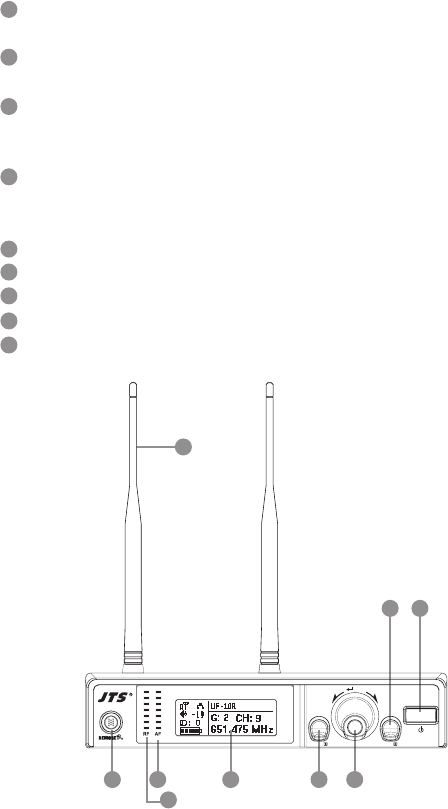
4-1 Broadband true diversity receiver key function and
LCD description//UF-10R
Power switch: press switch once to turn power on; press and hold for 2 seconds to shut
down.
EXIT key: when UF-10R is under “setup menu”, press EXIT to cancel selection or leave
menu.
Jog dial: when main menu is on screen, turn jog dial to adjust volume (MUTE,
-31~0dB); on “setup menu” screen, turn jog dial to select setup item, aer entering into the
selected item turn jog dial to adjust the value.
SETUP key: press and hold for 2 seconds to enter “setup menu”; press SETUP key to
enter into setup mode for jog dial; aer adjustment of value, press SETUP key to save the
seing.
REMOSET: Press REMOSET once to send frequency data to a microphone.
LCD: refer to “(2) Receiver LCD instruction”.
AF: indicate current audio signal strength.
RF: indicate current radio frequency signal strength.
Antenna: 1/2 wave length antenna.
1
4
7
2
5
8
3
6
9
12
3465 7
8
(1) Front panel
9
EXITSETUP
PUSH / CONTROL
UF-10R
wireless receiver
Professional Wideband (60~75MHz) True Diversity System
9
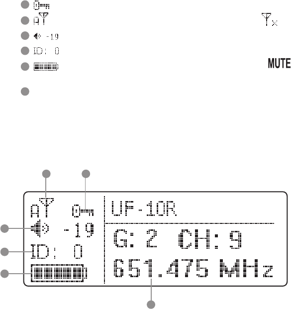
(2) Receiver LCD instruction
1011
12
13
14
15
15
11
12
13
14
10 : indicate key lock is set (Key lock on).
: show antenna A or B is receiving signal; signal is not received .
: indicate current receiver volume.
: indicate device ID seing: ID number 0~255.
: indicate transmier baery level; if no RF signal is received will show
up.
G: indicate current Group, 1~13
CH: indicate current Channel, CH1~63
Frequency indication: current operation frequency
10
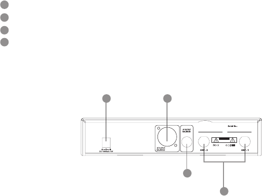
(3) Rear panel
Power receptacle: connect to power supply (DC15V/1000mA)
Balanced XLR MIC output
φ 6.3mm balanced output
BNC antenna socket: ANT 1 and ANT 2, set antennas vertical or sloping for beer
reception.
18
17
16
19
16 17
18
19
CAUTION
Freq.Range:
1856
Made in Taiwan
Note: select MIC or LINE audio output dierence:
From setup menu, set “7. OUTPUT LEVEL”:
Set Line: Output level of XLR MIC output and Ø 6.3mm are identical
Set Mic: XLR MIC output level is lower than Ø 6.3mm output by “-20dB”
Professional Wideband (60~75MHz) True Diversity System
11
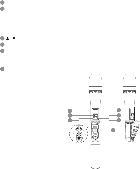
4-2 UHF PLL handheld transmitter key function and LCD description //
UF-10TH
LCD
Power key:
Turn on power: press power key once
Shut down power: press and hold power key for 2 seconds
Mute mode: during use, press power key once to mute the microphone, press it again to
release
, : up and down keys, select setup item
SET: set up and save data
Mute/REMOSET indicator lamp:
Mute mode: red light ashes
REMOSET successful: blue light on for 5 seconds
Baery compartment
20
21
22
23
24
25
20
25
21
22 22
23
24
For screen display and operation please refer to “6-2. System operation setup for
handheld transmier”.
12
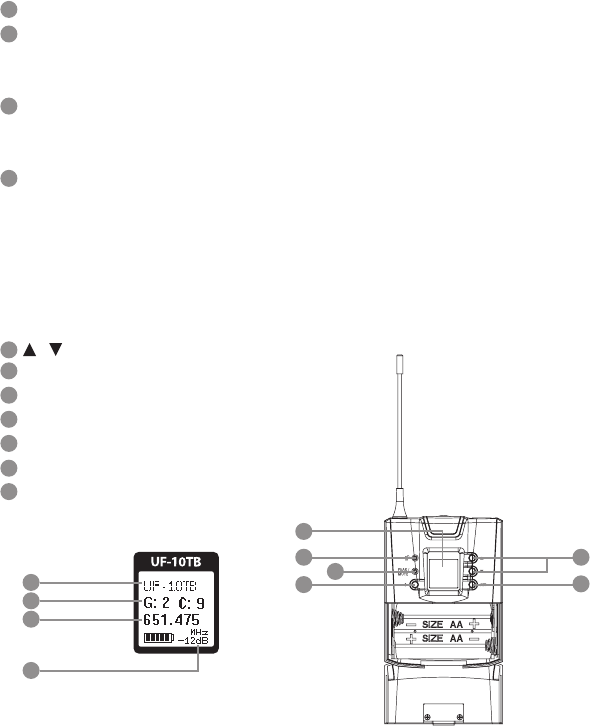
4-3 UHF PLL Body-Pack Transmitter // UF-10TB
LCD
Baery
Low Baery Indicator: when baery lever is low this red LED will light on constantly.
Note: when switch on the unit the red LED will light on for 1 second and turn o.
AF Peak and Mute Indicator
AF PEAK: Orange
Mute mode: Red light ashes
Power Key
(1) Turn on power: press power key once
(2) Shut down power: press and hold Power Key for 2 seconds
(3) Mute mode: during use, press Power Key once to mute the microphone, press it
again to release.
(4) Leave the seing window: press the power key once the LCD display will return to
the main window.
, : up and down keys, select setup item
SET : set up and save data
User Name
Indicate current Group and current Channel
Current operation frequency
Baery status: display baery status
Microphone sensitivity
26
27
28
29
30
31
32
33
34
35
36
26
27 30
31
28
29
32
33
34
36
For screen display and operation please refer to “6-3. System operation setup for
Body-Pack transmier”.
Professional Wideband (60~75MHz) True Diversity System
13
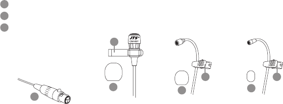
4-4 Optional Condenser Microphone
Clip
4 Pin Mini XLR
Windscreen
39
39 39 39
38
38
Lavaliere Microphone // CM-501 / CM-201 / CM-125
CM-501 CM-201 CM-125
37
37
37 37

14
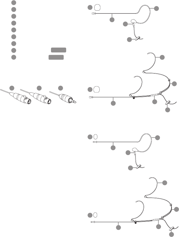
Gooseneck
Adjustable headband
Headband
4 Pin Mini XLR
Windscreen
CM-214 CM-214U
CM-235 CX-504
41
41 41
41
41
42
43
44
44 44
44
44
44
40
40
40
40
40
40
42
43
CM-214UL
Standard :
4 Pin Mini XLR
3 Pin Mini XLR
3.5 Stereo Plug
Headset Microphone // CM-214 / CM-214U / CM-214UL / CM-235 /
CX-504
Professional Wideband (60~75MHz) True Diversity System
15
Boom
Adjustable Headband
Adjustable ear hook
Detchable Cable
Cable Clip
Windscreen
4 Pin Mini XLR
3 Pin Mini XLR
3.5 Stereo Plug
Ear-hook Microphone // CM-801 / CM-804i / CM-8015 / CM-825i
50
52
52
51
53
53
47
49
51
48
45
46
CM-825i 49
50
45
47
48
46
Option
Option
CM-801
49
50
45
47
48
CM-804i 49
50
45
47
48
46
CM-8015
49
50
45
47
48
16
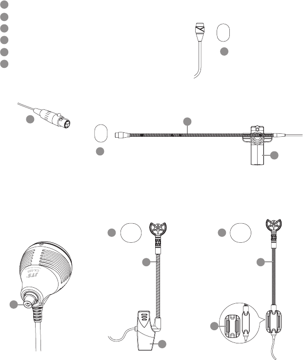
59
Gooseneck
Clip
Bracket
Volume Control
Windscreen
4 Pin Mini XLR
57
58
59
56
55
58
58
54
CX-520
CX-500F
CX-500
CX-516W
54
CX-508W
55
54
58 58
54
56
Compatible Instrument Microphone // CX-500 / CX-500F / CX-520 /
CX-508W / CX-516W
55
57
Professional Wideband (60~75MHz) True Diversity System
17
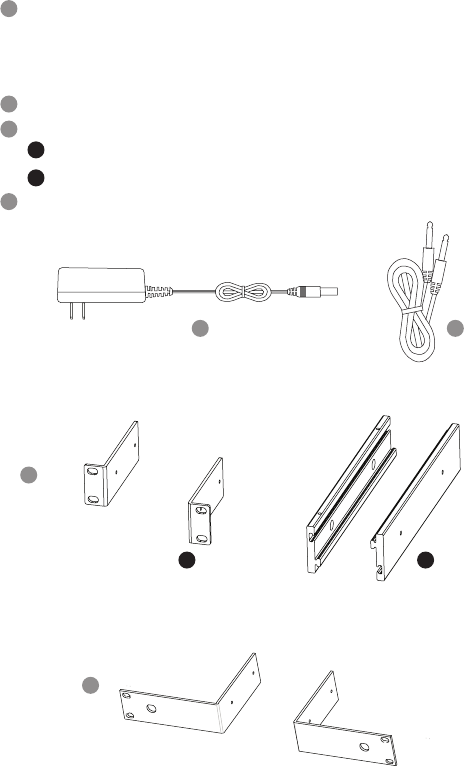
4-5 Accessories
AC/DC power adapter:
Switching power adapter
AC IN: AC100~240V/50~60Hz
DC OUT: DC15V/1000 mA
Audio cable
Rack mount kit//RM-10 (optional)
RM-10E
RM-10M
Rack mount kit//RM-901 (optional)
60
61
62
63
A
B
A B
60
62
63
61
18
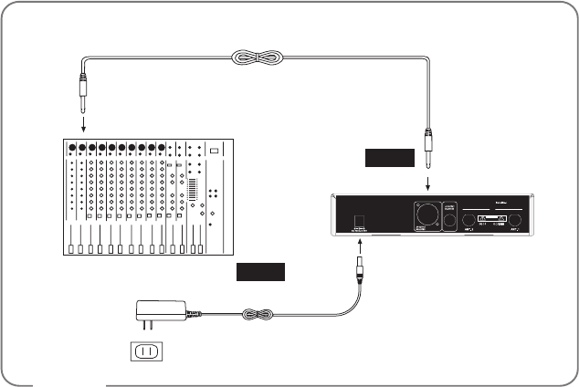
5. Connection method
1. UF-10R output to a mixer or an amplier:
Audio cable: XLR or φ 6.3mm audio cable, one end connects to audio output of UF-10R “AF
OUTPUT BALANCED”, while the other end connects to audio input of a mixer or an ampli-
er.
2. Connect to power
Connect to AC/DC adapter: one end connects to receiver “DCV INPUT”, while the other
end connects to AC power receptacle.
Receiver connection method
32
CAUTION
Freq.Range:
1856
Made in Taiwan
Figure 1
Amplier
AC/DC transformer
Power receptacle
Step 2
Step 1
Audio output
Power supply
Professional Wideband (60~75MHz) True Diversity System
19
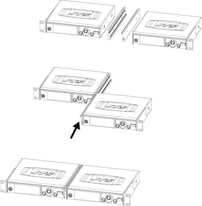
3. Receiver rack mount kit assembly//RM-10 (optional)
(1) Assembly the rack mount kit as the following illustration to mount two UF-10R into one
U rack.
(2) Lock equipment onto a rack

20
4. Rack Mount Kit RM-901 (optional)
Mount one UF-10R into one U rack.•
(1) Screw the rack mount kit on the receiver.
(2) screw the whole set onto a rack.
Professional Wideband (60~75MHz) True Diversity System
21
6. Operation
1. Turn receiver power on
(1) Connect antennas onto the receiver
(2) Press power key once to turn power on
(3) Shut down: press and hold power key for 2 seconds.
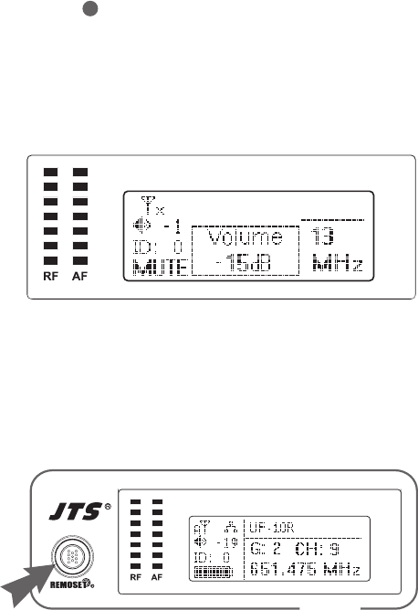
2. Adjust volume
On main menu, turn jog dial to adjust volume, ranging from MUTE, -31 ~ 0 dB.
6-1 Operation setup for broadband true diversity receiver system //
UF-10R
UF-10R
wireless receiver
1
3. REMOSET function:
(1) Pressing REMOSET key, blue light starts to ash, indicating transmiing frequency data.
(Fig. 1)
UF-10R
wireless receiver
Fig. 1
22
(2) When microphone receives data, microphone indicator lamp shows blue light for 5
seconds, while receiver blue light stops ashing, indicating the REMOSET has been done
successfully . (Fig. 2)
(3) Receiver blue light ashes slowly, indicating REMOSET failure, please check it:
1) Whether “frequency range labels” aached on receiver and microphone are the same.
2) “REMOSET” selection in microphone function menu needs to be set “ON”.
3) Device ID for receiver and microphone should be paired.
Refer to receiver setup method:
4. Menu function setup “6. Device ID: set device ID”
Refer to handheld transmier setup method:
6. Menu function setup “4. Device ID: set device ID”
4. Menu function setup:
Press Setup key for 2 seconds to enter menu screen
(1) Turn jog dial to make desired selection; press Setup key or press jog dial to enter setup
screen; press Exit key to leave menu.
(2) Aer entering into menu screen, turn jog dial to select default item; press Setup key or press
jog dial to enter into menu screen.
(3) Aer selecting the desired item, turn jog dial to obtain desired value; press Setup key to save
the seing.
Fig. 2
24

Professional Wideband (60~75MHz) True Diversity System
23
1. Frequency: set frequency
(1) Turn jog dial to “1. Frequency”, press Setup (or press jog dial)
to enter into frequency adjustment screen.
(2) Aer entering into frequency adjustment screen, rst adjust le
3 digit frequency; turn jog dial with “+/-” 1 MHz as unit change;
press jog dial to adjust right 3 digit frequency; press jog dial to
switch frequency between le and right.
(3) Adjust right 3 digit frequency; turn jog dial with “+/-”
0.025MHz as unit change; press Setup key to save seing.
2. Group/Channel: set group and channel
(1) Turn jog dial to “2. Group/Channel”, press Setup (or press jog
dial) to enter into setup screen.
(2) Turn jog dial to select group “G:”; group U1~U6 are user
self-dened group/channel, which needs to be preset in “3. User
Group” before use (please refer to “3. User Group” instructions
for setup); press jog dial to set channel.
(3) Turn jog dial to adjust channel “CH:”; aer adjustment, press
Setup key to save seing.
(4) If not to save seing, press Exit key twice to leave.
1. Frequency
2.Group/Channel
3.User Group
4. Scan
M
E
N
U
Setup Frequency
G: - - CH: - -
638 .000 MHz
Setup Frequency
G: - - CH: - -
638 . 000 MHz
1. Frequency
2.Group/Channel
3.User Group
4. Scan
M
E
N
U
Setup Group/Channel
638.100MHz
G: 1 CH: 1
Setup Group/Channel
638.100MHz
G: 1 CH: 1

24
1. Frequency
2.Group/Channel
3.User Group
4. Scan
M
E
N
U
1. Custom Group
2. Clear Group
3. Return
Setup Group/Channel
- - -,- - -MHz
G: U1 CH: 1
1. Custom Group
2. Clear Group
3. Return
Group: U1
Rotary to select
Push “Entry” to clear
Push “Exit” to return
1. Custom Group
2. Clear Group
3. Return
3. User Group: user self-dened group and channel
Turn jog dial to “3. User Group”, press Setup (or press jog dial) to
enter into User Group setup screen.
#1. Custom Group: self-dened group
(1) Turn jog dial to “1. Custom Group”; press jog dial to enter
into Custom Group screen.
(2) Enter into Custom Group screen; press jog dial to switch set-
ting from group (G), channel (CH), frequency in sequence; as
frequency area shows “- - - . - - -MHz”, it indicates the channel
(G/CH) is not in use; turn jog dial to adjust frequency.
#2. Clear Group: clear user self-dened groups
(1) Turn jog dial to “2. Clear Group”; press jog dial to enter into
Custom Group screen.
(2) Turn jog dial to select the group to clear; then press jog dial
to clear the seing for the group; the frequency for all chan-
nels in the group will become “- - -. - - - MHz”.
#3. Return: return to main menu
Turn jog dial to “3. Return”; press jog dial to return to main menu.

Professional Wideband (60~75MHz) True Diversity System
25
1. Frequency
2.Group/Channel
3.User Group
4. Scan
M
E
N
U
1. All Groups
2. Result List
3. Current Group
4. Return
Scan All Group
Press Setup or Enter to
To Start Scan.
Press Exit to quit.
Scan All Group
Scanning... 10%
Scan Result List
G: 1 CH: 1
Open Channel : 40
Scan Result List
G: 1 CH: 1
Open Channel : 40
4. Scan: scan channel
(1) Turn jog dial to “4. Scan”, press Setup (or press jog dial) to
enter into scan channel screen.
#1. All Groups: scan all groups
(1) Turn jog dial to “1. All Group”, press Setup (or press jog dial)
to enter into menu screen.
(2) Aer entering into the screen (press Exit to return to upper
menu); in “Scan All Group” press jog dial to start scanning.
(3) Scan screen indicates current percentage of completion; to
stop scan, press Exit key.
(4) Aer scan, automatically enter into “2. Result List” screen;
user can enter directly by selecting it on menu.
Scan result can be seen on screen; select available channel;
press Setup key to save seing; press Exit to cancel seing
#2. Result List: see scan list
Turn jog dial to 2. Result List; press Setup (or press jog dial) to
enter into menu screen to see scan result; select available chan-
nel; press Setup key to save seing; press Exit to cancel seing.

26
1. All Groups
2. Result List
3. Current Group
4. Return
Scan Current Group
G: 1 CH:1
1. All Groups
2. Result List
3. Current Group
4. Return
#3. Current Group: scan single channel
(1) Turn jog dial to “3. Current Group”; press jog dial to enter
into menu screen.
(2) Turn jog dial to select Group rst; press Setup key (or press
jog dial) to start scan.
(3) Aer scan, screen shows OK; press jog dial once to scan the
next channel; press Exit to return to upper menu.
#4. Return: return to main menu
Turn jog dial to “4. Return” ; press jog dial to return to menu
screen
5. Squelch: Adjust receiving sensitivity
(1) Turn jog dial to “5. Squelch”, press Setup (or press jog dial) to
enter into adjustment screen.
(2) Turn jog dial to adjust squelch, ranging from 10 ~ -5; 0 is
standard, press Setup key to save seing; higher number
represents lower sensitivity; lower number represents higher
sensitivity.
6. Device ID: set device ID
(1) Turn jog dial to “6. Device ID”, press Setup (or press jog dial)
to enter into ID adjustment screen.
Setup Squelch
0
5. Squelch
6. Device ID
7. Output Level
8. Antenna Power
M
E
N
U
5. Squelch
6. Device ID
7. Output Level
8. Antenna Power
M
E
N
U
Scan Current Group
Press "Setup" to Save.
G: U1 CH: 6 OK

Professional Wideband (60~75MHz) True Diversity System
27
Setup Device ID
6 (0~255)
(2) Turn jog dial to adjust ID, ranging 0~255; press Setup key
to save seing.
e seing will aect the use of REMOSET.
7. Output Level: set audio output level
(1) Turn jog dial to “7. Output Level”, press Setup (or press jog
dial) to enter into setup screen.
(2) Turn jog dial to select Line or Mic:
- Set Line: XLR MIC Output and Ø6.3mm output volume
level is same.
- Set Mic: XLR MIC Output volume is lower than Ø6.3 mm
output by -20dB.
(3) Press Setup key to save seing
8. Antenna Power: Set power on/o provided at BNC con-
necters
(1) Turn jog dial to “8. Antenna Power”, press Setup (or press
jog dial) to enter into adjustment screen.
(2) Turn jog dial to select ON or OFF to turn on or shut
down antenna booster power; press Setup key to save seing.
5. Squelch
6. Device ID
7. Output Level
8. Antenna Power
M
E
N
U
Output Levell
Line
Mic.
5. Squelch
6. Device ID
7. Output Level
8. Antenna Power
M
E
N
U
Antenna Power
ON
OFF
28
9. User Name: set user name
(1) Turn jog dial to “9. User Name”, press Setup (or press jog
dial) to enter into User Name setup screen.
(2) Turn jog dial to select desired character; aer conrmation
press jog dial to go to next character setup; aer setup press
Setup key to save seing.
A user name consists of 10 characters at maximum.
a. Contrast: adjust screen contrast
(1) Turn jog dial to “a. Contrast”, press Setup (or press jog dial) to
enter into setup screen.
(2) Turn jog dial to adjust screen contrast; aer conrmation
press Setup key to save seing; higher number represents
darker color; 7 adjustable levels.
b. Key Lock: set key lock
(1) Turn jog dial to “b. Key Lock”, press Setup (or press jog dial)
to enter into setup screen.
(2) Turn jog dial to select “Lock On”; aer conrmation press
Setup key to save seing; “Lock On” can lock all panel keys to
prevent accidental touch except “ Setup” key.
9. User Name
a. Contrast
b. Key Lock
c. Exit
M
E
N
U
User Name
JTS UF-10R
Char:1/10
10 characters
available
Indicate which
character currently
is set
9. User Name
a. Contrast
b. Key Lock
c. Exit
M
E
N
U
Setup Contrast
4/7
9. User Name
a. Contrast
b. Key Lock
c. Exit
M
E
N
U
Setup Key Lock
Lock On
Lock Off

Professional Wideband (60~75MHz) True Diversity System
29
9. User Name
a. Contrast
b. Key Lock
c. Exit
M
E
N
U
(3) At Lock On statue pressing of any key will prompt texts as
shown in the gure.
(4) Cancel Lock On: press SETUP key for 2 seconds to go
directly to “Key Lock” setup screen.
Turn jog dial to select Lock O; aer conrmation press Setup
key to save seing.
c. Exit: leave menu
Turn jog dial to “c. Exit”; press Setup key (or press jog dial) to
return to main menu; or press “exit” to return to main menu.
Setup Key Lock
Lock On
Lock Off
Press Setup for 2 Sec.
to unlock keyPad

30
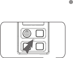
1. Turn power on for UF-10TH handheld transmier
(1) Turn on power: press power key once (Fig. 3).
(2) Shut down power: press and hold power key for
2 seconds.
(3) Mute setup:
When microphone is in use and mute setup is
needed:
Set mute: short press power key once; indicator lamp
ashes in red.
Cancel mute: short press power key again to cancel
mute.
6-2 System operation setup for handheld transmitter // UF-10TH
Fig. 3
Fig. 3
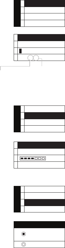
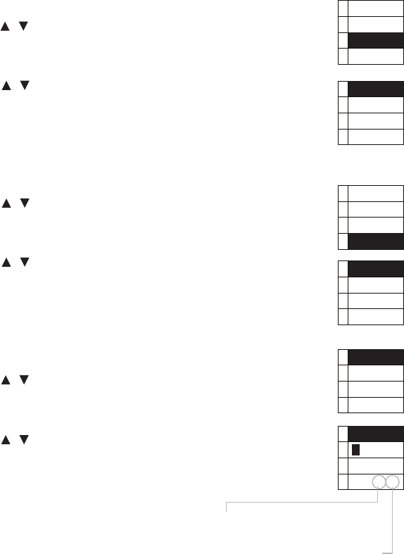
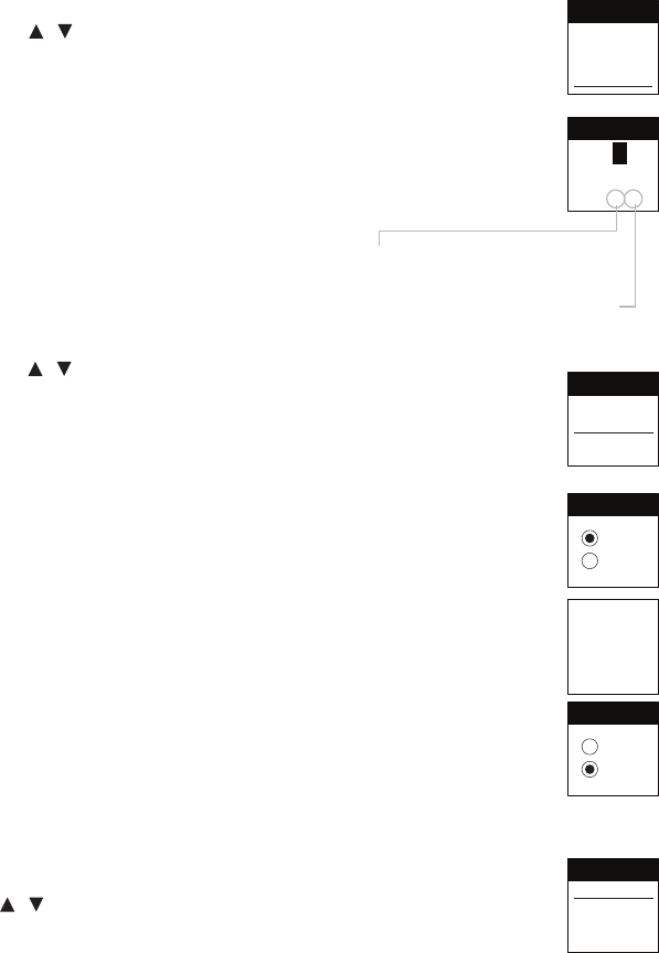
2. Menu function setup:
Press and hold SET key for 2 seconds; enter into function setup menu;
(1) Press , keys to select desired item; press SET key to enter into menu.
(2) Aer entering into menu, press , keys to adjust to desired value;
press SET key to save seing.
1. Freq.: set frequency
(1) Press , keys to Freq.; press SET key to enter into frequency adjust-
ment screen.
(2) Aer going to frequency adjustment screen, rst adjust le 3 digit frequen-
cy; press , keys with “+/-” 1 MHz as unit change; aer adjustment
press SET key to adjust right 3 digit frequency
Freq.
Group
Sensit.
Device ID
Frequency
G:- - C:- -
638.100
Professional Wideband (60~75MHz) True Diversity System
31
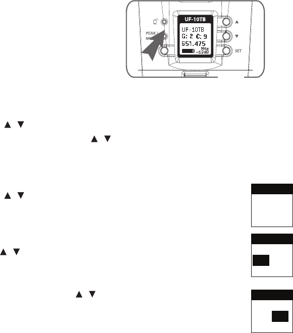
(3) Adjust right 3 digit frequency: press , keys with “+/-” 0.025 MHz as
unit change; aer adjustment press SET key to save seing.
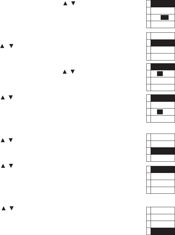
2. Group: set group and channel
(1) Press , keys to Group; press SET key to enter into “Group” setup
screen.
(2) Aer entering into the screen, press , keys to select the desired group;
press SET key to switch to Channel setup.
(3) Press , keys to select the desired channel; press SET key to save
seing.
3. Sensit: microphone sensitivity setup
(1) Press , keys to Sensit; press SET to enter into “Sensit” sensitivity
setup screen.
(2) Press , keys to adjust sensitivity with 3dB as unit change; adjustment
range from -18dB to +12dB.
4. Device ID: set device ID
(1) Press , keys to Device ID; press SET key to enter into “Device ID”
setup screen.
Frequency
G:- - C:- -
638.100
Freq.
Group
Sensit.
Device ID
Group/Channel
G: 1
C: 1
638.100
Group/Channel
G: 1
C: 1
638.100
Freq.
Group
Sensit.
Device ID
Sensitivity
3db
Freq.
Group
Sensit.
Device ID
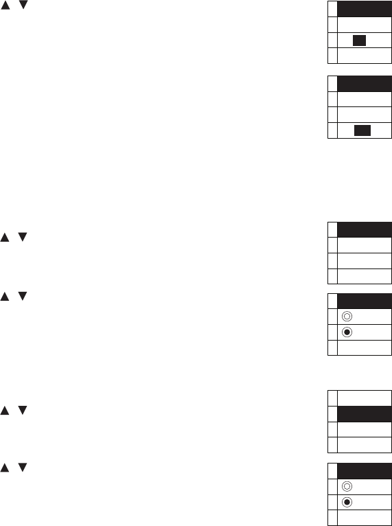
32
Device ID
0
ID:OFF
Device ID
0
ID: ON
REMOSET
RF Power
Contrast
Light T.
Remote Set
ON
OFF
REMOSET
RF Power
Contrast
Light T.
RF Power
Hi
Low
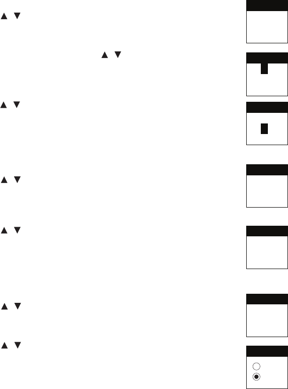
(2) Press , keys to adjust default ID between 0 and 255; press SET key to
switch to set ID: ON/OFF.
ID: ON → only if microphone ID and receiver ID are the same, REMOSET
function can work.
ID: OFF → regardless of ID, the transmier will accept REMOSET data from
all receivers of the same band and with ID O.
e seing will aect the use of REMOSET.
5. REMOSET: set REMOSET function on/o
(1) Press , keys to REMOSET; press SET to enter into “REMOSET”
setup screen.
(2) Press , keys to select ON or OFF; press SET key to save seing.
Seing ON: REMOSET function available.
Seing OFF: disenable REMOSET function; and saves microphone power.
6. RF Power: set transmission power
(1) Press , keys to RF Power; press SET to enter into “RF Power” screen;
set transmission power.
(2) Press , keys to select transmission power as Hi or Low; press SET
key to save seing.
Aention: if seing is Hi, microphone consumes more power.
Note: Hi represents 50 mW and Low 10 mW.
Professional Wideband (60~75MHz) True Diversity System
33
7. Contrast: adjust screen contrast
(1) Press , keys to Contrast; press SET to enter into “Contrast” screen;
adjust screen contrast.
(2) Press , keys to adjust contrast; higher number represents higher
contrast; otherwise, lower contrast; -3 ~ 0 ~ +3 total seven adjustable
levels.
8. Light T.: set screen backlight time
(1) Press , keys to Light T.; press SET to enter into “Light T.” screen; set
screen backlight time.
(2) Press , keys to select backlight time;
3 options available; Always OFF (shut o), 5~30Sec (5 Sec as unit
change), Always ON (always on).
e longer screen backlight time, the shorter baery life.
9. Name: set user name
(1) Press , keys to Name; press SET to enter into “Name” screen; set
user name.
(2) Press , keys to select texts; aer conrmation press SET key to set
the next character; if no characters is needed, select “blank” character;
aer conrmation press SET key to save seing; Name consists of 10
characters at maximum.
REMOSET
RF Power
Contrast
Light T.
Contrast
0
REMOSET
RF Power
Contrast
Light T.
Light Time
5 Sec.
Name
UF-10T
Char:1 / 10
Name
Key Lock
Exit
--------------
10 characters
available
Indicate which
character currently
is set

34
Press Set
For 2 Sec.
to unlock
Keypad.
10. Key Lock: set key lock
(1) Press , keys to Key Lock; press SET to enter into “Key Lock” screen;
set key lock
(2) Select “Lock On” to lock all keys to prevent accidental touch; if seing is
Lock On, mute function is not aected.
(3) If seing is “Lock On”, except mute, pressing any other keys will prompt
the following screen.
(4) Cancel Lock On: press SETUP key for 2 seconds to go directly to “Key
Lock” setup screen, select “Lock O”.
11. Exit: leave function setup menu
Press , keys to Exit; press SET key to leave menu.
Name
Key Lock
Exit
--------------
Key Lock
Lock On
Lock Off
Lock On
Lock Off
Key Lock
Light T.
Name
Key Lock
Exit
Professional Wideband (60~75MHz) True Diversity System
35
6-3 System operation setup for Body-Pack transmitter // UF-10TB
6-3-1 Turn power on for UF-10TB Body-Pack transmier (Fig. 5)
(1) Turn on power: press power key once
(2) Shut down power: press and hold power key for 2 seconds.
(3) Mute setup : When microphone is in use and mute setup is needed:
Set mute: short press power key once; indicator lamp ashes in red.
Cancel mute: short press power key again to cancel mute.
(4) Leave the seing window: press the power key once the LCD display will return to the
main window.
6-3-2 Menu function setup :
Press and hold SET key for 2 seconds; enter into function setup menu;
(1) Press , keys to select desired item; press SET key to enter into menu.
(2) Aer entering into menu, press , keys to select desired value : press
SET key to save seing.
1. Freq.: set frequency
(1) Press , keys to Freq. ; press SET key to enter into frequency adjustment
screen.
(2) Aer going to frequency adjustment screen, rst adjust le 3 digits ;
Press , keys with “+/-” 1 MHz as unit change; aer adjustment press
SET key to adjust right 3 digits
(3) Adjust right 3 digits : press , keys with “+/-” 0.025 MHz as unit change;
aer adjustment press SET key to save seing.
UHF PLL Transmitter
Fig. 5
Freq.
Group
Sensit.
Attenuate
Frequency
G: 1 C:1
625 .500
Frequency
G: 1 C:1
625 . 500
36
2. Group: set group and channel
(1) Press , keys to Group; press SET key to enter into “Group” setup screen.
(2) Aer entering into the screen, press , keys to select the desired group ;
press SET key to switch to Channel setup.
(3) Press , keys to select the desired channel; press SET key to save seing.
3. Sensit: microphone sensitivity setup
(1) Press , keys to Sensit; press SET to enter into “Sensit” sensitivity setup
screen.
(2) Press , keys to adjust sensitivity with 3dB as unit change ; press SET key
to save seing ; adjustable range from -18dB to +12dB.
4. Aenuate : Microphone Aenuate
(1) Press , key to Aenuate. Press SET to enter “Aenuate”setup screen.
(2) Press , key to select ON or OFF
ON: -20dB aenuation
OFF: No aenuation
Group
Sensit.
Attenuate
Device ID
Group/Chan
G: 1
C: 1
625 . 500
Group/Chan
G: 1
C: 1
625 . 500
Sensit.
Attenuate
Device ID
Remoset
Sensitivity
12 dB
Attenuate
Device ID
Remoset
RF Power
ON
OFF
Attenuate
Professional Wideband (60~75MHz) True Diversity System
37
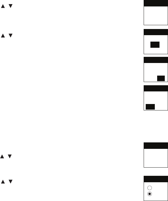
5. Device ID: set device ID
(1) Press , keys to Device ID; press SET key to enter into “Device ID” setup
screen.
(2) Press , keys to adjust default ID between 0 and 255; press SET key to
switch to set ID: ON/OFF.
ID: ON → only if microphone ID and receiver ID are the same , REMOSET
function will work.
ID: OFF → regardless of ID, the transmier will accept REMOSET data from all
receivers of the same band and with ID O.
Press SET key to save seing.
e seing will aect the use of REMOSET.
6. REMOSET: set REMOSET function on/o
(1) Press , keys to REMOSET; press SET to enter into “REMOSET” setup
screen.
(2) Press , keys to select ON or OFF; press SET key to save seing.
Seing ON: REMOSET function available.
Seing OFF: disenable REMOSET function; and saves microphone power.
Device ID
Remoset
RF Power
Contrast
Device ID
255
ID : OFF
Device ID
255
OFF / ON
Device ID
0
OFF / ON
Remoset
RF Power
Contrast
Light T.
Remote Set
ON
OFF

38
7.RF Power: set transmission power
(1) Press , keys to RF Power; press SET to enter into “RF Power” screen;set
transmission power.
(2) Press , keys to select transmission power as Hi or Low; press SET key
to save seing.
Aention: if seing is Hi, the RF signal is stronger while microphone consumes
more power.
Note: Hi represents 50 mW and Low 10 mW.
8. Contrast: adjust screen contrast
(1) Press , keys to Contrast; press SET to enter into “Contrast” screen ;
adjust screen contrast.
(2) Press , keys to adjust contrast; higher number represents higher
contrast ; otherwise, lower contrast; -3 ~ 0 ~ +3 total seven adjustable levels.
9.Light T.: set screen backlighting time
(1) Press , keys to Light T.; press SET to enter into “Light T.” screen; set
screen backlight time.
(2) Press , keys to select backlight time 3 options available; Always OFF
(shut o), 5~30Sec (5 Sec as unit change), Always ON (always on).
e longer screen backlight time, the shorter baery life.
RF Power
Contrast
Light T.
Name
RF Power
Hi
Low
Contrast
Light T.
Name
Key Lock
Contrast
0
Light T.
Name
Key Lock
Exit
Light Time
30 Sec.
Professional Wideband (60~75MHz) True Diversity System
39
10.Name: set user name
(1) Press , keys to Name; press SET to enter into “Name” screen; set user
name.
(2) Press keys to select texts; aer conrmation press SET key to set the next
character; if no characters is needed, select “blank” character; aer conrmation
press SET key to save seing; Name consists of 10 characters at maximum.
11.Key Lock :
(1) Press , keys to Key Lock; press SET to enter into “Key Lock” screen; set
Key Lock
(2) Select “Lock On” to lock all keys to prevent accidental touch; if seing is Lock
On, mute function is not aected.
(3) If seing is “Lock On”, except mute, pressing any other keys will prompt the
following screen.
(4) Cancel Lock On: press SETUP key for 2 seconds to go directly to “Key
Lock” setup screen, select “Lock O ”.
Press SET key to save seing.
12.Exit: leave function setup menu
Press , keys to Exit; press SET key to leave menu.
Note: Pressing the power key will make the LCD back to main window.
Name
Key Lock
Exit
User Name
UF-1 0 TB
Char: 5/10
Key Lock
Exit
Freq.
Key Lock
ON
OFF
Press Set
for 2 Sec.
to unlock
keypad.
Key Lock
ON
OFF
Exit
Freq.
Group
10 characters
available
Indicate which
character currently
is set
40
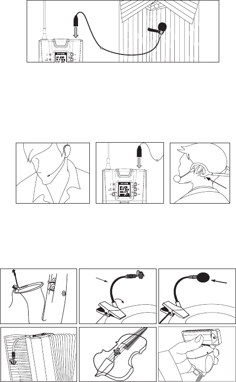
6-4 Installation of Condenser Microphones
(1) Lavaliere microphone
Aach lavaliere microphone to a tie, lapel, where is suitable for sound pick-up. Plug the
connector into input socket on the body-pack transmier.
(2) Headset microphone
Put the headband behind your head, and x the temples on your ears as shows, then
adjust the gooseneck to have best miking. Plug the connector into input socket on the
body-pack transmier.
MIC IN
(3) Instrument Microphones
e system is compatible with JTS various instrument microphones.
For detail please refer to user’s manuals of these microphones.
UHF PL L T ra nsm itt er
UHF PL L T ra nsm itt er
Professional Wideband (60~75MHz) True Diversity System
41
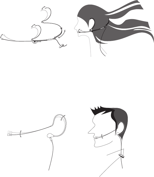
(4) Ear-hook Microphone
1. Lightweight Dual Ear Hook Microphone
Try on whether the headset is t.
Adjust the headband to a suitable width.
Tighten or loosen the curve of the ear-hook by twisting the loop or expanding it.
Curve and bend the boom to t your face.
Aach the detachable cable to a suitable place by a cable clip.
2. Lightweight Single Ear Hook Microphone
Try on whether the original curve is tight or loose.
Re-try and push the xed curve against your earlobe.
Curve and Bend the boom to t your face.
Aach the detachable cable to a suitable place by a cable clip.
42
7. Product notes
(1) To get the best signal performance, please keep at least 3 meters between a receiver and a
transmier.
(2) Keep a receiver and transmier from other metal object for at least 50cm.
(3) To prevent feedback and whistle, please do not aim transmier to speaker.
(4) It is suggested to hold the middle section of transmier (microphone) body to achieve the
best pickup eect.
(5) When multiple units are in use, it is suggested to use JTS UA-900 antenna distributor to
prevent interference.
(6) When transmier is not used for a long time, please remove baeries from baery compart-
ment to avoid leakage of electrolyte solution to damage transmier.
(7) When replacing baeries, please replace two baeries at the same time and use the same
brand of baery, to assure the best power performance.
Professional Wideband (60~75MHz) True Diversity System
43
8. Important Notice
(1) JTS oers wireless systems in a selection of bands that conform to the dierent government
regulations of specic nations or geographic regions. ese regulations help limit radio
frequency (RF) interference among dierent wireless devices and prevent interference with
local public communications channels, such as television and emergency broadcasts.
(2) For information on bands available in your area, consult your local dealer or phone JTS.
More information is also available at JTS’s website (www.jts.com.tw).
(3) is Radio apparatus may be capable of operating on some frequencies not authorized in
your region. Please contact your national authority to obtain information on authorized
frequencies and RF power levels for wireless microphone products.
(4) The changes or modifications not expressly approved by the party responsible for
compliance could void the user’s authority to operate the equipment.
(5) To comply with the FCC RF exposure compliance requirements, no change to the antenna
or the device is permitted. Any change to the antenna or the device could result in the
device exceeding the RF exposure requirements and void user’s authority to operate the
device.
44