JULONG EDUCATIONAL TECHNOLOGY L-RFBT1 wireless module transmitter User Manual
JULONG EDUCATIONAL TECHNOLOGY CO., LTD. wireless module transmitter
User Manual
USER__ GUIDE
Page 2/10
1. Product Introduction
This wireless module is a short-range data transmission and receiving equipment specially
developed for the interactive whiteboard. Data can be inter-transmitted between the whiteboard
and the PC upon connection.
Connected to the PC, the wireless module enables users to operate the whiteboard or the
computer freely as they are not limited by cables.
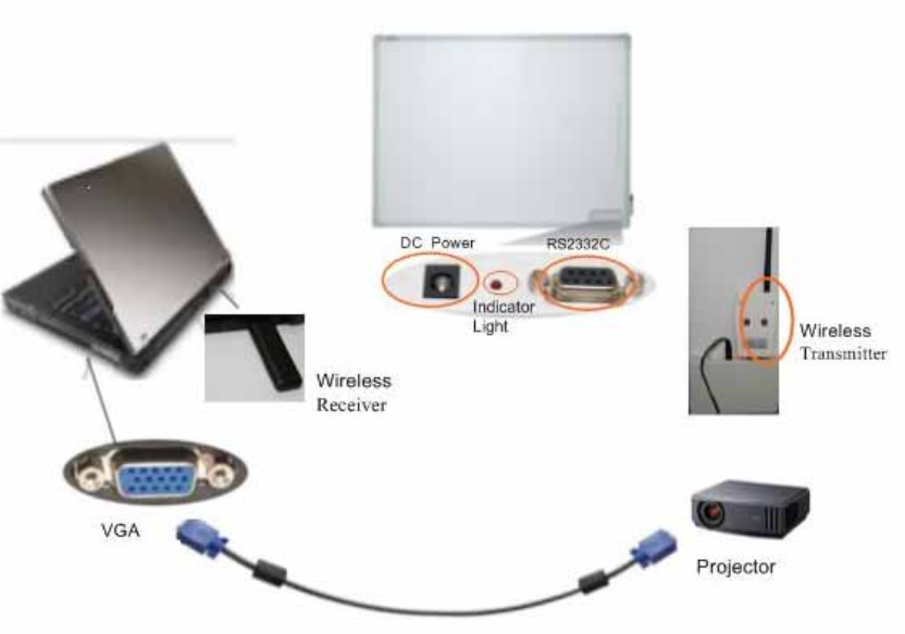
Topological Diagram as shown below:
Page 3/10
2. Product Features
z Fully compliant with USB 2.0 standards.
z Supports RS232 serial port.
z Fully plug-and-play.
z Full-duplex and bus-powered USB.
z Launch with low power, LED indicator for transmission and reception.
When the Wireless Transmitter and the Wireless Receiver are connected correctly, the LED
indicator is red, or it will be flash one time a second. During transmission, the LED indicator is
red and flash with long time until the transmission is end.
z Smart data transfer, data transmission is fully automatic. All controls or transformation of signals
shall be completed automatically. It can connect different type of whiteboard by set up the
baud rate by the user.
z High reliability, small size, light and portable.
Page 4/10
Monolithic RFIC and single-chip MCU is used, thus there is less periphery circuit which ensures
high performance reliability. The chips are overmolded by epoxy resins which are excellent
electrical insulation materials. They protect integrated components from short circuiting, dust,
humidity and other environmental factors that could damage the device.
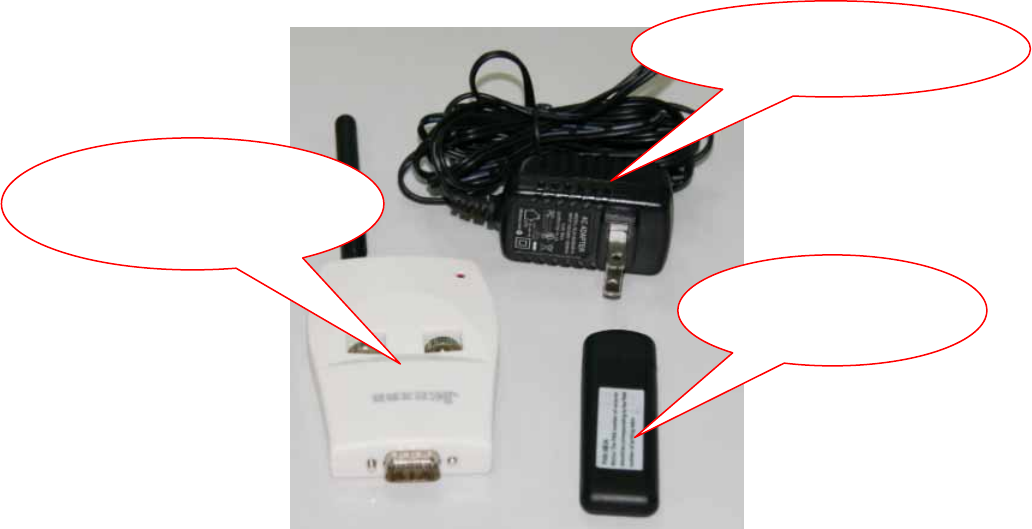
3. Product Components
This product is composed of the interactive whiteboard connector(Wireless Transmitter), PC
connector(Wireless Receiver) and Power Adapter.
The products said as shown below:
Power Adapter
Wireless
Transmitter
Wireless
Receiver
Page 5/10
4. Product Hardware Installation
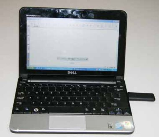
Step1:USB PC connector:
Connect the Wireless Receiver to a USB port on the PC. As shown below:
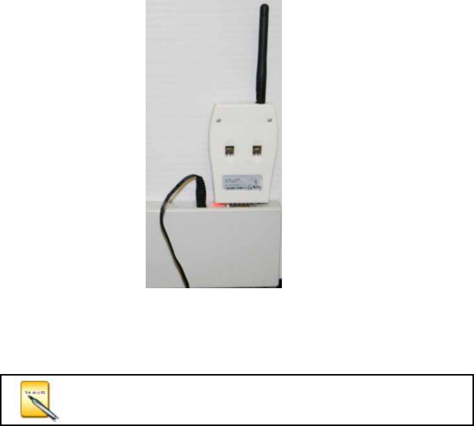
Step2:Interactive whiteboard connector:
First, RS232 Connector(Wireless Transmitter) connect the interfaces on the whiteboard.
Then connect the Power Adapter to the interfaces of DC Power on the whiteboard. As shown
below:
Page 6/10
5. The Installation of the Driver of the USB PC Connector.
Please follow the instructions as shown below to install the Driver of the USB PC Connector
underWindows XP.
If the Wireless Module is used, the corresponding driver must be
installed. Or else, the interactive whiteboard will can not exchange
the data communication with the PC correctly.
Page 7/10
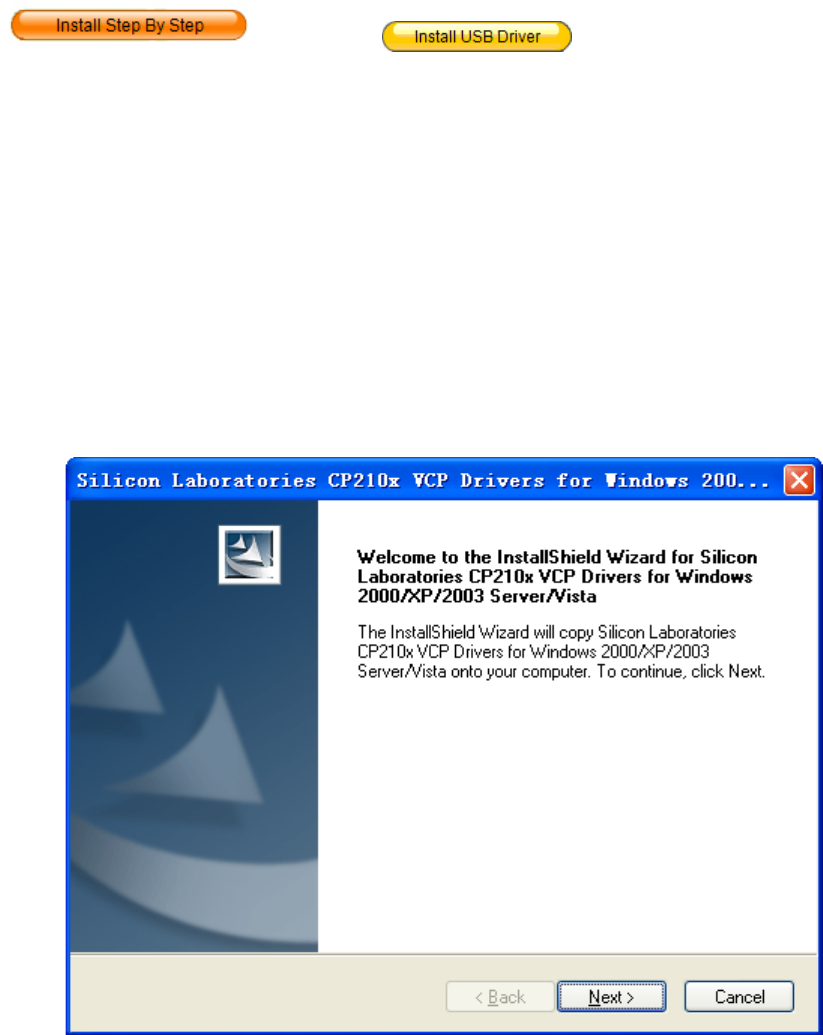
Please insert the disc of the whiteboard. When it pop up the interface of installation guide,
click ,then click , and select ”Install Silicon
Driver” ,then begin the installation of the USB Cable Driver.
(1) Click “Next”, the confirmation prompt of Silicon USB driver installation appears:
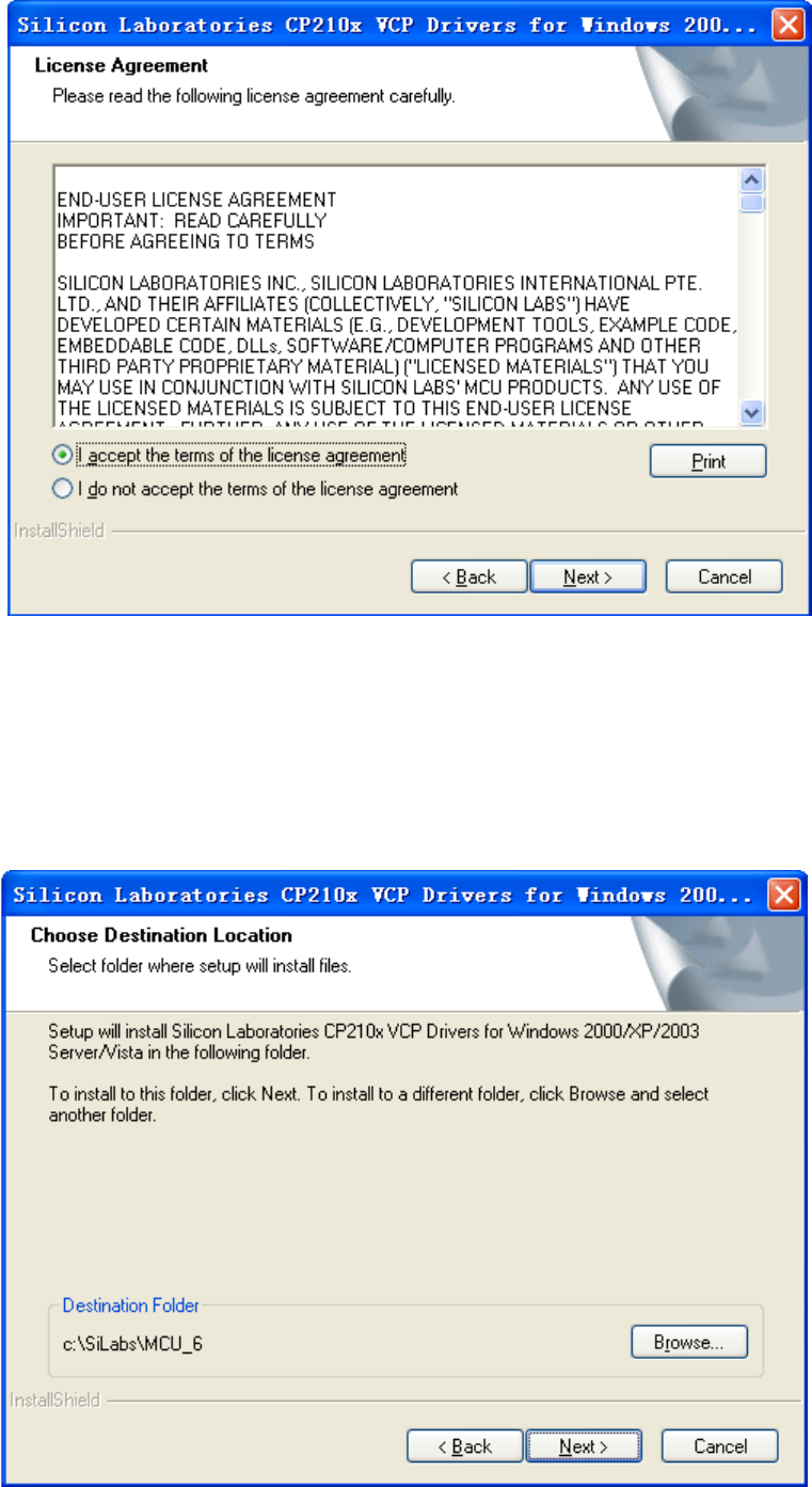
(2) Click “Next”, enter into installation license agreement: select “I accept the terms of the
license agreement”, and then click ”Next”.
Page 8/10
(2) Select folder where setup will install files. Click “Browse” to set the destination location.
The default path is “c:\SiLabs\MCU_6”, and then click “Next”.
Page 9/10
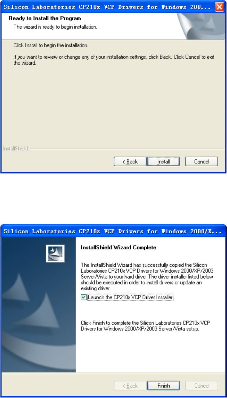
(4) Click “Install” to start the installation.
(5) Select “Launch the CP210x VCP Driver Installer”, then click “Finish”.
FCC S: TA TEM ENT:
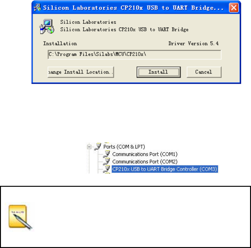
(6) Click “Install” to start the driver installation.
(7) Complete installation.
After installing correctly in “My Computer” → “Properties” → “Hardware” → “Device Manager” →
“Port” can see the device “CP210X USB to UART Bridge Controller”
After installation of USB-RS232 cable is completed, plug-in the USB
cable, and to check the COM number of the
CP210X USB to UART
Bridge Controller
in “My Computer”→“Properties”→“Hardware”→ “Device Manager”
→“Port” and to make sure that the COM number is less then 10 and
the baud rate is 19200.
1. This device complies with Part 15 of the FCC Rules. Operation is subject to the following two
conditions:
(1) This device may not cause harmful interference.
(2) This device must accept any interference received, including interference that may cause
undesired operation.
2. Changes or modifications not expressly approved by the party responsible for compliance could
void the user's authority to operate the equipment.
NOTE: This equipment has been tested and found to comply with the limits for a Class B digital
device, pursuant to Part 15 of the FCC Rules. These limits are designed to provide reasonable
protection against harmful interference in a residential installation.
This equipment generates uses and can radiate radio frequency energy and, if not installed and
used in accordance with the instructions, may cause harmful interference to radio communications.
However, there is no guarantee that interference will not occur in a particular installation. If this
equipment does cause harmful interference to radio or television reception, which can be
determined by turning the equipment off and on, the user is encouraged to try to correct the
interference by one or more of the following measures:
Reorient or relocate the receiving antenna.
Increase the separation between the equipment and receiver.
Connect the equipment into an outlet on a circuit different from that to which the receiver is
connected.
Consult the dealer or an experienced radio/TV technician for help.