JVC KENWOOD 31201110 HF/VHF/UHF All-mode Multi-band Transceiver User Manual 0 Front page
JVC KENWOOD Corporation HF/VHF/UHF All-mode Multi-band Transceiver 0 Front page
UserManual.wiki
>
JVC KENWOOD
>
31201110 User Manual
Users Manual
Navigation menu
Upload a User Manual
Namespaces
Wiki Guide
HTML
PDF
Info
Views
User Manual
Discussion / Help
Navigation
![yrosseccA rebmuNtraP ytitnauQ0002-ST X0002-ST 0002B-STenohporciMXX-2530-19T11elbacrewopCDXX-7513-03E11gulpNIDnip-7XX-1570-70E11gulpNIDnip-8XX-1580-70E11gulpNIDnip-31XX-1531-70E11)A52(esuFXX-1352-50F11)A4(esuFXX-7204-60F11teSwercSXX-4202-99N11034-BMrofrecapSXX-8962-11G44retlifeniL1XX-8041-97L11dnaBgniniateR1XX-7030-16J11MOR-DCXX-3210-39T–1launaMnoitcurtsnIXX-2121-26B11kcolB/citamehcS smargaiDXX-4160-25B XX-6160-25B XX-7160-25B 11dracytnarraWXX-9640-64B )epyt-K( XX-0130-64B )sepyt-EllA(11THANK YOUTHANK YOUThank you for choosing this KENWOOD TS-2000(X)/TS-B2000 transceiver. It has been developed by ateam of engineers determined to continue thetradition of excellence and innovation in KENWOODtransceivers.This transceiver features dual Digital SignalProcessing (DSP) units to process IF and AF signals.By taking maximum advantage of DSP technology,the TS-2000(X) gives you enhanced interferencereduction capabilities and improves the quality ofaudio that you transmit without installing additionalanalog filters. You will notice the differences whenyou fight QRM and QRN. As you learn how to usethis transceiver, you will also find that KENWOOD ispursuing “user friendliness”. For example, each timeyou change the Menu No. in Menu mode, you will seescrolling messages on the display that tell you whatyou are selecting.Though user friendly, this transceiver is technicallysophisticated and some features may be new to you.Consider this manual to be a personal tutorial fromthe designers. Allow the manual to guide you throughthe learning process now, then act as a reference inthe coming years.FEATURES• All mode operation from HF to 1.2 GHz (TS-2000/TS-B2000 Optional) amateur radio band with DSPfunctions.• Dual high speed Digital Signal Processing (DSP)units.• Adjustable DSP filter frequencies.• High speed Digital Automatic Gain Control (AGC).• A second independent sub-receiver for the 144 MHzand 430 (440) MHz bands (FM and AM mode only).• A built-in Antenna Tuner for HF/ 50 MHz band.• A built-in 9600/ 1200 bps TNC for packet operation.• DX PacketCluster Tune (P.C.T.) for DX hunting.• Instant Satelite communication key.• A razor sharp DSP filter up to 50 Hz for CWoperation.SUPPLIED ACCESSORIESAfter carefully unpacking the transceiver, identify theitems listed in the table. We recommend you keepthe box and packing material below in case you needto repack the transceiver in the future.1 E and E2-type onlyWRITING CONVENTIONS FOLLOWEDThe writing conventions described below have beenfollowed to simplify instructions and avoidunnecessary repetition.noitcurtsnI oDottahWsserP ]YEK[ .esaelerdnasserP YEK .sserP ]1YEK[ ,]2YEK[ .sserP 1YEK ,yliratnemomesaeler 1YEK sserpneht,2YEK .sserP ]2YEK[+]1YEK[ .dlohdnasserP 1YEK neht,sserp 2YEK eromeraerehtfI. dlohdnasserp,syekowtnaht lanifehtlitnunrutniyekhcae .desserpneebsahyeksserP +]YEK[NOREWOP .rewopreviecsnartehthtiW dlohdnasserp,FFO YEK ,reviecsnartehtNOnrutneht gnisserpybrewop ]REWOP[ .](https://usermanual.wiki/JVC-KENWOOD/31201110/User-Guide-119445-Page-3.png)
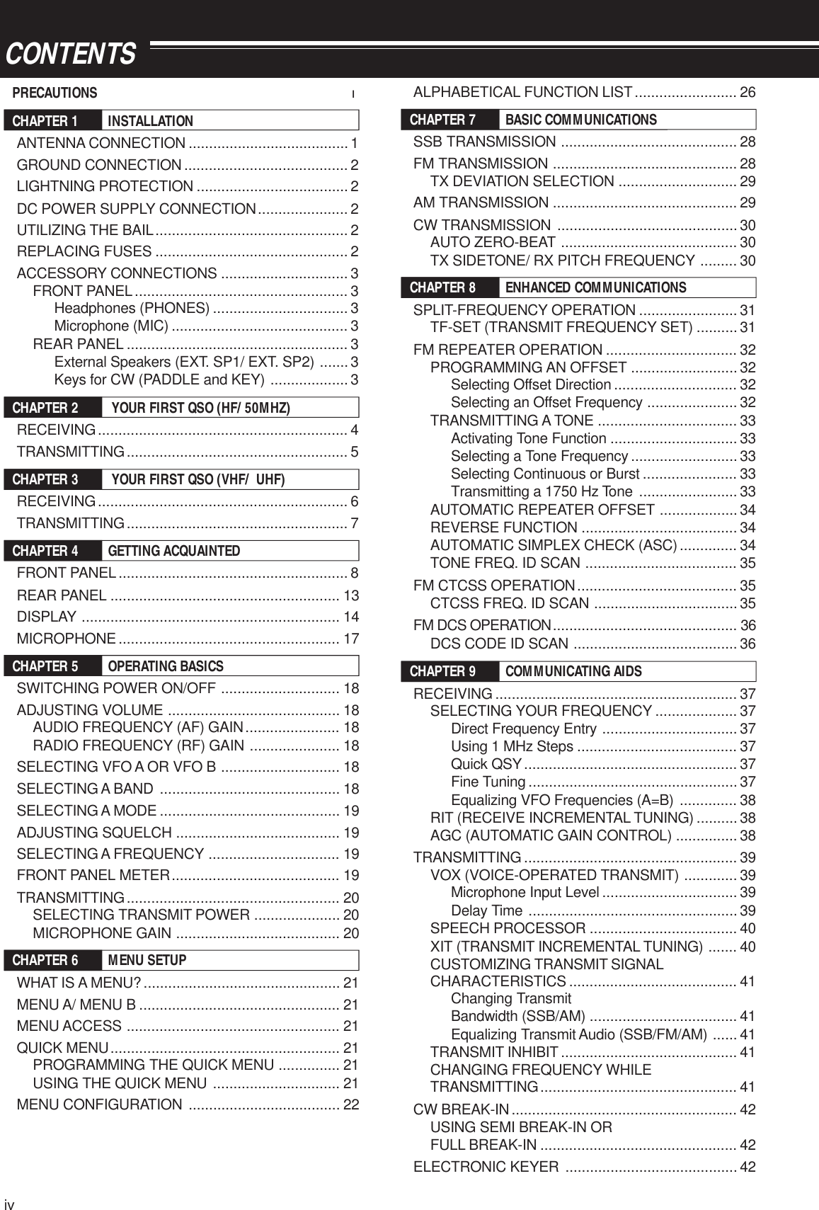
![YOUR FIRST QSO (HF/ 50 MHz band)4YOUR FIRST QSORECEIVINGAre you ready to give your TS-2000(X) a quick try? Reading these two pages should get your voice on theair in your first QSO on the HF/ 50 MHz band shortly. The instructions below are intended only for a quickguide. If you encounter problems or there is something you don’t understand, read the detailed explanationsgiven later in this manual.Note: This section explains only keys and controls required tobriefly try the transceiver.qSet the following as specified:•MAIN AF: Fully counterclockwise•MAIN RF GAIN: Fully clockwise•MAIN SQL: Fully counterclockwisewSwitch ON the DC power supply, then pressand hold [ ] (POWER) briefly on thetransceiver.• Do not press the switch for more thanapproximately 2 seconds; the transceiverwill be switched OFF.• Upon power up, “HELLO” appears,followed by the selected frequency andother indicators.eConfirm that VFO A has been selected forcommunications; “tA” should be visible onthe display. If it has not, press [A/B] to selectVFO A.rTurn the MAIN AF control slowly clockwiseuntil you hear a suitable level of backgroundnoise.tPress [+] or [–] to select an HF/ 50 MHzAmateur radio band.PFF LOCK A1CH1/REC2CH2/REC3CH3/REC4TONE/SEL5METER6CTCSS/SEL7NB/LEVEL8AGC/OFF9FINE/STEP.DCS/SEL0SHIFT/OFFSETENTSENDPHONESMICATANT1/2PROCLEVELVOXATT PRELEVELLEVELLEVELMANUALLO/WIDTHHI/SHIFTN.R.A.N.B.C.FUNCCALLC.INCLRMAINAUTOCARTX MONIDELAY NARREVMICPWRKEYLSBUSBCWFSKFM AMSUBDISPSEL1MHz CTRLMRMG.SELM.INQUICK MEMOM/S REVTRACEMAINMANUALRFAFSQLSUBCHMULTIBC MAINGAINVFO/CHMENU TF-SETMAIN SUBSG.SELSCAN M VFO M.INRITCW TUNE 9.6k STARIT/SUBCONXITALTSETCLEARP.C . T_+HF/VHF/UHF ALL MODE MULTI BANDER TS-2000SATLA/BVFO/MSPLITA=B6218 5 3 1 7 1 4FILTERS13579204060dBPWR102550100WALCdyPress [LSB/ USB/ AUTO] or [FM/ AM/ NAR] toselect an operating mode.• To select the second mode on each button,press the same button again. For example,each press of [LSB/ USB/ AUTO] switchesbetween LSB and USB modes.uIf you have selected FM, turn the MAIN SQLcontrol clockwise until the background noise isjust eliminated; The MAIN band LED (above the[MIC/ CAR] key) turns off.• With LSB or USB selected, skip this step.iTurn the Tuning control to tune in a station.• If you do not hear any stations, you may havethe wrong antenna connector selected. Press[FUNC], [AT/ ANT 1/2] to switch between theantenna 1 and 2 connectors.](https://usermanual.wiki/JVC-KENWOOD/31201110/User-Guide-119445-Page-12.png)
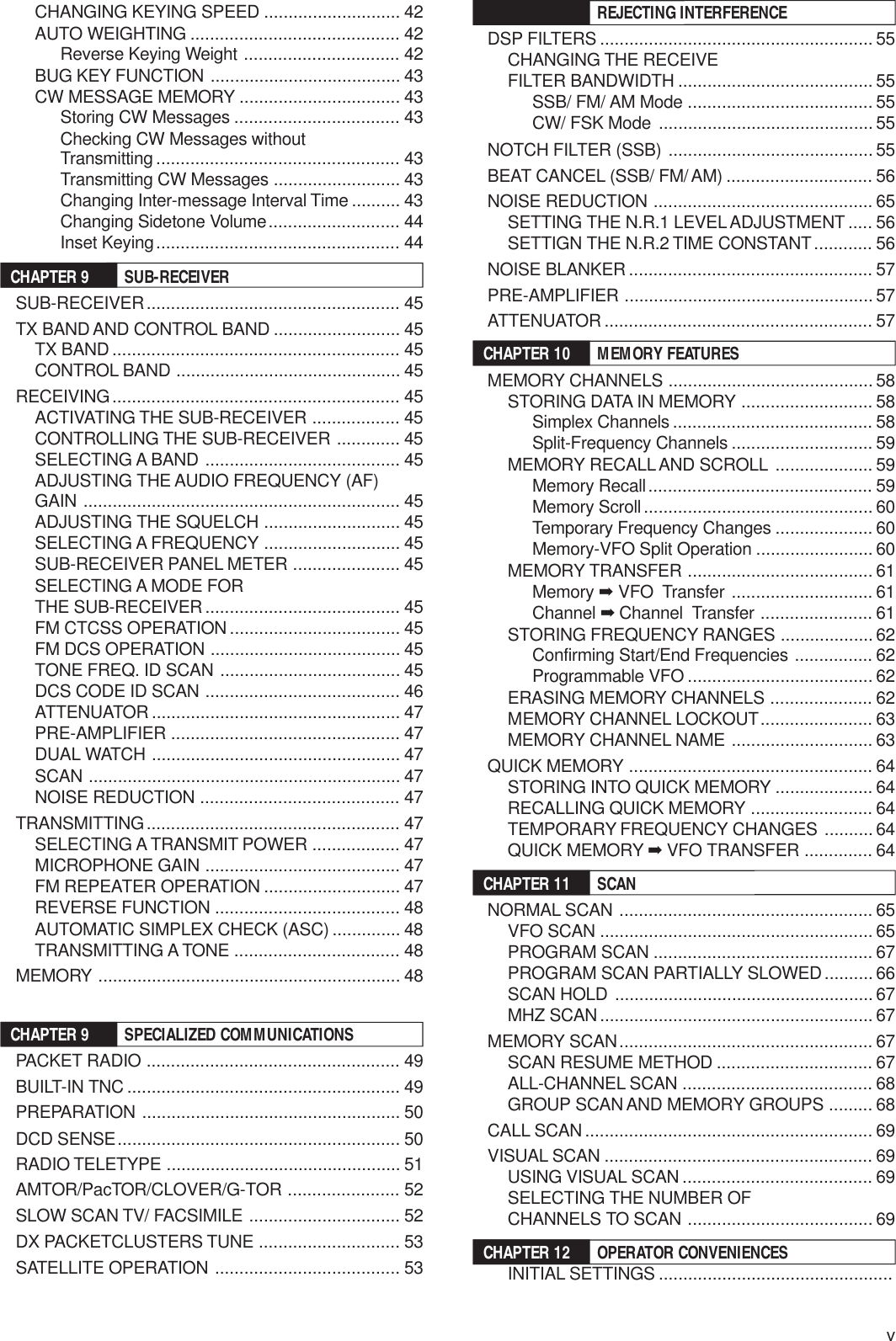
![5TRANSMITTING2 YOUR FIRST QSO (HF/ 50 MHz band)q Turn the Tuning control to tune in a desiredstation or to select an unused frequency.wPress [AT/ ANT 1/2] momentarily.• “AT” appears.ePress and hold [AT/ ANT 1/2] to activate thebuilt-in antenna tuner.• “AT” starts blinking and the MAIN band LEDabove the [MIC/ CAR] key turns red.• Tuning should be completed in under20 seconds, then “AT” stops blinking.• If tuning is not completed within 20 seconds,error beeps sound. Press [AT/ ANT 1/2] tostop the error beeps and quit tuning. Checkyour antenna system before continuing. If youdo not press [AT/ ANT 1/2], tuning will continuefor approximately 60 seconds.Note: You will hear a lot of clicking sounds coming from thetransceiver while the antenna tuner is trying to tune theantenna. This is simply the relay switches turning ON and OFF.rWith LSB, USB, or AM selected, press[MIC/ CAR] to activate the Microphone GainAdjust.• “MIC GAIN 50” appears.• With FM selected, skip this step.tPress [SEND].• The MAIN band LED turns red.yBegin speaking into the microphone in yournormal tone of voice.uLSB/ USB: While speaking into themicrophone, adjust the MULTI/ CH control sothat the ALC meter reflects according to yourvoice level.AM: While speaking into the microphone,adjust the MULTI/ CH control so that thecalibrated power meter slightly reflects to yourvoice level.FM: Skip this step.i When you finish speaking, press [SEND] toreturn to receive mode.oPress [MIC/ CAR] to quit the Microphone GainAdjustment.Note: If desired, access Menu No. 41 {page 28} to try theMicrophone Gain Adjust for FM.This completes your introduction to theTS-2000(X), but there is a great deal more toknow. “OPERATING BASICS” {page 18} and thefollowing chapters explain all the functions of thistransceiver, starting with the most basic,commonly-used functions.PFF LOCK A1CH1/REC2CH2/REC3CH3/REC4TONE/SEL5METER6CTCSS/SEL7NB/LEVEL8AGC/OFF9FINE/STEP.DCS/SEL0SHIFT/OFFSETENTSENDPHONESMICATANT1/2PROCLEVELVOXATT PRELEVELLEVELLEVELMANUALLO/WIDTHHI/SHIFTN.R.A.N.B.C.FUNCCALLC.INCLRMAINAUTOCARTX MONIDELAY NARREVMICPWRKEYLSBUSBCWFSKFM AMSUBDISPSEL1MHz CTRLMRMG.SELM.INQUICK MEMOM/S REVTRACEMAINMANUALRFAFSQLSUBCHMULTIBCMAINGAINVFO/CHMENU TF-SETMAIN SUBSG.SELSCAN M VFO M.INRITCW TUNE 9.6k STARIT/SUBCONXITALTSETCLEARP.C.T_+HF/VHF/UHF ALL MODE MULTI BANDER TS-2000SATLA/BVFO/MSPLITA=B4 9718532FILTERS13579204060dBPWR102550100WALCFILTERS13579204060dBPWR102550100WALCPWR102550100WFILTERS13579204060dBALC](https://usermanual.wiki/JVC-KENWOOD/31201110/User-Guide-119445-Page-13.png)
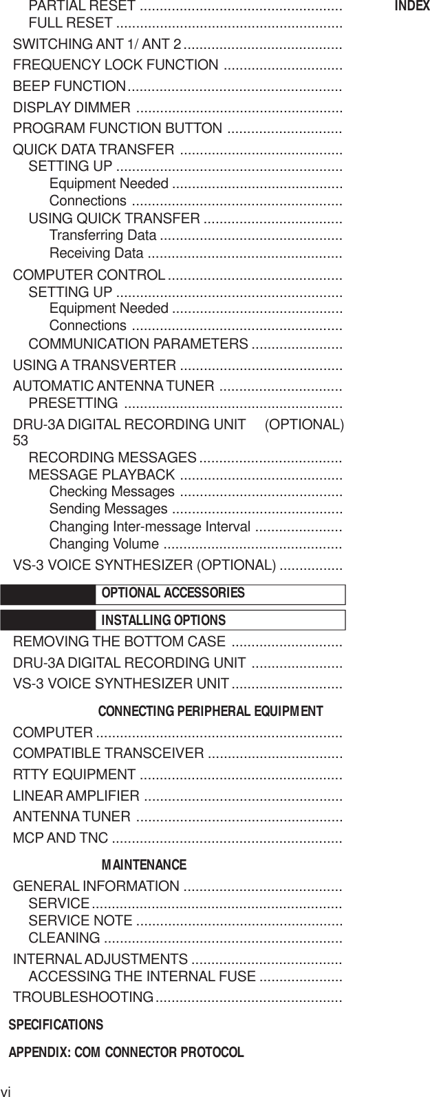
![YOUR FIRST QSO (VHF/ UHF band)6YOUR FIRST QSORECEIVINGePress [MAIN], then confirm that VFO A hasbeen selected for communications; “tA”should be visible on the display. If it has not,press [A/B] to select VFO A.rTurn the MAIN AF control slowly clockwiseuntil you hear a suitable level of backgroundnoise.tPress [+] or [–] to move up to the VHF(144 MHz) or UHF (430/ 440 MHz) Amateurradio band.If your primary operating band is VHF (144 MHz) or UHF (430/ 440 MHz), the TS-2000(X) can also serve youas a powerful All-mode VHF/ UHF transceiver. The instructions below are intended only for a quick guide toget you up on the air on the VHF/ UHF band. If you encounter problems or there is something you don’tunderstand, read the detailed explanations given later in this manual.Note: This section explains only keys and controls required tobriefly try the transceiver.qSet the following as specified:•MAIN AF: Fully counterclockwise•MAIN RF GAIN: Fully clockwise•MAIN SQL: Fully counterclockwisewSwitch ON the DC power supply, then pressand hold [ ] (POWER) briefly on thetransceiver.• Do not press the switch for more thanapproximately 2 seconds; the transceiverwill be switched OFF.• Upon power up, “HELLO” appears,followed by the selected frequency andother indicators.yConfirm that the operating mode is FM. If it is not,press [FM/ AM/ NAR] to select FM.uTurn the SQL control clockwise until thebackground noise is just eliminated; The MAINband LED turns off.iTurn the Tuning control to tune in a station.• You can use the MULTI/ CH control to changethe frequency faster. If you do not hear anystations, the antenna may not be installed orconnected properly. Check the antennaconnector on the rear panel {page 13}.PFF LOCK A1CH1/REC2CH2/REC3CH3/REC4TONE/SEL5METER6CTCSS/SEL7NB/LEVEL8AGC/OFF9FINE/STEP.DCS/SEL0SHIFT/OFFSETENTSENDPHONESMICATANT1/2PROCLEVELVOXATT PRELEVELLEVELLEVELMANUALLO/WIDTHHI/SHIFTN.R.A.N.B.C.FUNCCALLC.INCLRMAINAUTOCARTX MONIDELAY NARREVMICPWRKEYLSBUSBCWFSKFM AMSUBDISPSEL1MHz CTRLMRMG.SELM.INQUICK MEMOM/S REVTRACEMAINMANUALRFAFSQLSUBCHMULTIBC MAINGAINVFO/CHMENU TF-SETMAIN SUBSG.SELSCAN M VFO M.INRITCW TUNE 9.6k STARIT/SUBCONXITALTSETCLEARP.C . T_+HF/VHF/UHF ALL MODE MULTI BANDER TS-2000SATLA/BVFO/MSPLITA=B6218 5 3 1 7 1 4FILTERS13579204060dBPWR102550100WALCFILTERS13579204060dBPWR102550100WALC](https://usermanual.wiki/JVC-KENWOOD/31201110/User-Guide-119445-Page-14.png)
![73 YOUR FIRST QSO (VHF/ UHF band)TRANSMITTINGqConfirm that the operating mode is FM. If it isnot, press [FM/ AM/ NAR] to change theoperating mode to FM.w Turn the Tuning control or the MULTI/ CHcontrol to tune in a desired station or to select anunused frequency.ePress [SEND].• The MAIN band LED turns red.rBegin speaking into the microphone in yournormal tone of voice.tWhen you finish speaking, press [SEND] toreturn to receive mode.This completes your introduction on how to receiveand transmit using the TS-2000(X) on a VHF/ UHFband. Refer to “OPERATING BASICS” {page 18}and the following chapters for explanations on allthe functions of this transceiver.FILTERS13579204060dBPWR102550100WALCPFF LOCK A1CH1/REC2CH2/REC3CH3/REC4TONE/SEL5METER6CTCSS/SEL7NB/LEVEL8AGC/OFF9FINE/STEP.DCS/SEL0SHIFT/OFFSETENTSENDPHONESMICATANT1/2PROCLEVELVOXATT PRELEVELLEVELLEVELMANUALLO/WIDTHHI/SHIFTN.R.A.N.B.C.FUNCCALLC.INCLRMAINAUTOCARTX MONIDELAY NARREVMICPWRKEYLSBUSBCWFSKFM AMSUBDISPSEL1MHz CTRLMRMG.SELM.INQUICK MEMOM/S REVTRACEMAINMANUALRFAFSQLSUBCHMULTIBC MAINGAINVFO/CHMENU TF-SETMAIN SUBSG.SELSCAN M VFO M.INRITCW TUNE 9.6k STARIT/SUBCONXITALTSETCLEARP.C .T_+HF/VHF/UHF ALL MODE MULTI BANDER TS-2000SATLA/BVFO/MSPLITA=B1 23 5](https://usermanual.wiki/JVC-KENWOOD/31201110/User-Guide-119445-Page-15.png)
![8GETTING ACQUAINTEDq PF keyYou can assign a function to this ProgrammableFunction key. The default function is Voice 1{page 77}.w [ ] (POWER) switchPress and hold briefly to switch the transceiver powerON. Press again to switch the power OFF.e ATT/ F LOCK keyPress to switch the receiver attenuator ON or OFF{page 57}. Press [FUNC], [ATT/ F LOCK] to switchthe Frequency Lock function ON or OFF {page 76}.r PRE/ LOCK A keyPress to switch the receiver pre-amplifier ON or OFF{page 57}. Press [FUNC], [PRE/ LOCK A] to lock allthe transceiver keys {page 77}.t VOX/ LEVEL keyIn voice mode, press to switch the Voice-OperatedTransmit function ON or OFF {page 39}. In CWmode, press to switch the Break-in function ON orOFF {page 42}. Press [FUNC], [VOX/ LEVEL] toadjust the microphone input level for VOX operation.The VOX LED lights orange when the VOX function isactive.y PROC/ LEVEL keyPress to switch the Speech Processor for transmittingON or OFF {page 40}. Press [FUNC],[PROC/ LEVEL] to adjust the Speech Processorinput level. The PROC LED lights orange when theSpeech Processor function is active.u SEND keyPress to switch the transceiver between receivemode and transmit mode {page 5, 7}.FRONT PANELi AT/ ANT 1/2 keyPress to activate the internal antenna tuner {page 72}or an external antenna tuner. Press [FUNC],[AT/ ANT 1/2] to select either Antenna 1 or Antenna 2for the HF/ 50 MHz band.o PHONES jackConnect a set of headphones to this jack. Inserting aplug into the jack automatically mutes the audio fromthe speaker {pages 3, 78}.!0 MIC connectorConnect a compatible microphone to this connector,then securely screw down the connector locking ring{page 3}.!1 N.R./ LEVEL keyPress to switch the DSP Noise Reduction functionON or OFF. Press [FUNC], [N.R./ LEVEL] to adjustthe Noise Reduction level. Press [FUNC],[N.R./ LEVEL] again to finish the adjustment{page 56}.!2 A.N./ LEVEL keyPress to switch the DSP Auto Notch function ON orOFF. Press [FUNC], [A.N./ LEVEL] to adjust theDSP Auto Notch reduction level. Press [FUNC],[A.N./ LEVEL] again to finish the adjustment{page 56}.!3 B.C./ MANUAL keyPress to switch the DSP Auto Beat Canceler functionON or OFF. Press [FUNC], [B.C./ MANUAL] toadjust the beat cancel frequency manually. Press[FUNC], [B.C./ MANUAL] again to finish the manualadjustment {page 56}.PFF LOCK A1CH1/REC2CH2/REC3CH3/REC4TONE/SEL5METER6CTCSS/SEL7NB/LEVEL8AGC/OFF9FINE/STEP.DCS/SEL0SHIFT/OFFSETENTSENDPHONESMICATANT1/2PROCLEVELVOXATT PRELEVELLEVELLEVELMANUALLO/WIDTHHI/SHIFTN.R.A.N.B.C.FUNCCALLC.INCLRMAINAUTOCARTX MONIDELAY NARREVMICPWRKEYLSBUSBCWFSKFM AMSUBDISPSEL1MHz CTRLMRMG.SELM.INQUICK MEMOM/S REVTRACEMAINMANUALRFAFSQLSUBCHMULTIBC MAINGAINVFO/CHMENU TF-SETMAIN SUBSG.SELSCAN M VFO M.INRITCW TUNE 9.6k STARIT/SUBCONXITALTSETCLEARP.C . T_+HF/VHF/UHF ALL MODE MULTI BANDER TS-2000SATLA/BVFO/MSPLITA=B23546789101112131](https://usermanual.wiki/JVC-KENWOOD/31201110/User-Guide-119445-Page-16.png)
![4 GETTING ACQUAINTED9!4 Multi-purpose keypadConsists of 10 keys that are used to enter numericdata. Also used for the following functions:•1/ CH1/REC, 2/ CH2/REC, and 3/ CH3/REC keysPress to play back or record the CW or voicemessages that are associated with the DRU-3ADigital Recording Unit {page 89} and the internalelectronic keyer {page 43} .•4/ TONE/SEL keyPress to activate the sub-audible Tone function toaccess repeaters for FM mode. To select the Tonefrequency, press [FUNC], [4/ TONE/SEL], thenselect your desired tone frequency using theMULTI/ CH control {page 33}.•5/ METER keyPress to select the meter scales {page 14}.•6/ CTCSS/SEL keyPress to activate the Continuous Tone CodedSquelch System (CTCSS) function for FM mode.To select the CTCSS tone frequency, press[FUNC], [5/ CTCSS/SEL], then select yourdesired CTCSS tone frequency using theMULTI/ CH control {page 35}.•7/ NB/LEVEL keyPress to switch the analog Noise Blanker ON orOFF. Press [FUNC], [7/ NB/LEVEL] to adjust theNoise Blanker level {page 57}.•8/ AGC/OFF keyPress to adjust the response time of the AutomaticGain Control. To switch the AGC OFF, press[FUNC], [8/ AGC/OFF] {page 38}.•9/ FINE/STEP keyPress to activate the Fine tuning mode to allowmore precise tuning {page 38}.••/ DCS/SEL keyPress to activate the Digital Coded Squelchfunction for FM mode. To select the DCS code,press [FUNC], [•/ DCS/SEL], then select yourdesired code using the MULTI/ CH control {page36}.•0/ SHIFT/OFFSET keyPress to switch the Shift function for FM mode ONor OFF when accesing the repeaters. The Shiftfrequency can be manually adjusted by pressing[FUNC], [0/ SHIFT/OFFSET], then adjusting theshift frequency value using the MULTI/ CH control{page 32}.•ENT keyPress to enter your desired frequency using thekeypad {page 37}.!5 FUNC keyPress to access the secondary functions that areassigned to the keys. While FUNC is active, theFUNC LED lights orange.!6 MIC/ CAR keyPress to adjust the microphone gain {page 20}.While the Speech Processor function is ON, itbecomes the Speech Processor output leveladjustment key.Press [FUNC], [MIC/ CAR] to adjust the carrier levelfor CW, FSK and AM mode {pags 20}.!7 PWR/ TX MONI keyPress to adjust the output power {page 20}. Press[FUNC], [PWR/ TX MONI] to monitor yourtransmission signal {page 79}.!8 KEY/ DELAY keyPress to adjust the internal electronic keyer speed.Press [FUNC], [KEY/ DELAY] to adjust the VOXdelay time or break-in time (Full break-in/ Semibreak-in time) for CW mode {page 42}.PFF LOCK A1CH1/REC2CH2/REC3CH3/REC4TONE/SEL5METER6CTCSS/SEL7NB/LEVEL8AGC/OFF9FINE/STEP.DCS/SEL0SHIFT/OFFSETENTSENDPHONESMICATANT1/2PROCLEVELVOXATT PRELEVELLEVELLEVELMANUALLO/WIDTHHI/SHIFTN.R.A.N.B.C.FUNCCALLC.INCLRMAINAUTOCARTX MONIDELAY NARREVMICPWRKEYLSBUSBCWFSKFM AMSUBDISPSEL1MHz CTRLMRMG.SELM.INQUICK MEMOM/S REVTRACEMAINMANUALRFAFSQLSUBCHMULTIBCMAINGAINVFO/CHMENU TF-SETMAIN SUBSG.SELSCAN M VFO M.INRITCW TUNE 9.6k STARIT/SUBCONXITALTSETCLEARP.C . T_+HF/VHF/UHF ALL MODE MULTI BANDER TS-2000SATLA/BVFO/MSPLITA=B1718151416](https://usermanual.wiki/JVC-KENWOOD/31201110/User-Guide-119445-Page-17.png)
![104 GETTING ACQUAINTED!9 LSB/ USB/ AUTO keyPress to select lower sideband (LSB) or uppersideband (USB) mode for voice or digital operation.Press [FUNC], [LSB/ USB/ AUTO] to toggle the automode selection {page 73}.@0 CW/ FSK/ REV keyPress to select CW or FSK (Frequency Shift Keying)mode {pages 30, 51}. Press [FUNC],[CW/ FSK/ REV] to reverse the sideband pitch.@1 FM/ AM/ NAR keyPress to select FM or AM mode. Press [FUNC],[FM/ AM/ NAR ] to select narrow bandwidthtransmission mode {page 29}.@2 CLR keyPress to exit from, abort, or reset various functions.Also used to erase memory channels {page 62} orlocking out memory channels from the scan list {page62}.@3 DISP keyPress to toggle the normal operating mode and DSPfilter setting display mode {page 55}. Press and holdto start the Visual Scan function {page 70}.@4 1MHz/ SEL keyPress to switch the MHz Up/ Down function ON orOFF using the MULTI/ CH control. Press [FUNC],[1MHz/ SEL] to change the increment/ decrementstep value {page 37}. Press and hold to start theMHz Scan function {page 68}.@5 Tuning controlTurn to select the desired frequency {page 37}. Use theconvenient finger-tip cavity for continuous tuning.The lever behind this control adjusts the control torquelevel; turn fully clockwise for light torque or fullycounterclockwise for heavy torque.@6 CTRL keyPress to toggle the operating controls between themain transceiver and the sub-receiver. Thetransmission band is not affected by this key.@7 MENU keyPress to select or cancel the Menu mode that is usedfor activating and configuring functions {page 21}.@8 TF-SET keyWhile operating split-frequency, press to monitor orchange your transmit frequency {page 31}.@9 +/ – (Up/ Down) keysPress to step through all the Amateur radio bandsconsecutively {page 18}. Also used to makeselections from the Menu {page 21}, and to check theStart and End frequencies of the Scan function{page 62}.#0 MAIN keyPress to transfer the operating controls to the MAINtransceiver. Also moves the transmission band to themain transceiver frequency.#1 SUB keyPress to transfer the operating controls to the sub-receiver. Also moves the trasmission band to thesub-receiver frequency.#2 SCAN/ SG.SEL keyPress to start or stop the Scan function {page 66}.Press [FUNC], [SCAN/ SG.SEL] to select a scangroup {page XX}.#3 CALL/ C.IN keyPress to recall a call channel for the selectedoperating band (HF/ 50 MHz/ 144 MHz/ 430(440) MHz/ 1.2 GHz (TS-2000 Optional). Press[FUNC], [CALL/ C.IN] to write a new Call Channel tothe memory {page 75}.PFF LOCK A1CH1/REC2CH2/REC3CH3/REC4TONE/SEL5METER6CTCSS/SEL7NB/LEVEL8AGC/OFF9FINE/STEP.DCS/SEL0SHIFT/OFFSETENTSENDPHONESMICATANT1/2PROCLEVELVOXATT PRELEVELLEVELLEVELMANUALLO/WIDTHHI/SHIFTN.R.A.N.B.C.FUNCCALLC.INCLRMAINAUTOCARTX MONIDELAY NARREVMICPWRKEYLSBUSBCWFSKFM AMSUBDISPSEL1MHz CTRLMRMG.SELM.INQUICK MEMOM/S REVTRACEMAINMANUALRFAFSQLSUBCHMULTIBCMAINGAINVFO/CHMENU TF-SETMAIN SUBSG.SELSCAN M VFO M.INRITCW TUNE 9.6k STARIT/SUBCONXITALTSETCLEARP.C . T_+HF/VHF/UHF ALL MODE MULTI BANDER TS-2000SATLA/BVFO/MSPLITA=B21 24232519 27 28 3320 292226 3230 31](https://usermanual.wiki/JVC-KENWOOD/31201110/User-Guide-119445-Page-18.png)
![4 GETTING ACQUAINTED11#4 QUICK MEMO keysControls the Quick Memory function {page 64}.•MR keyPress to recall data from the Quick Memory{page 65}.•M.IN keyPress to write data into the Quick Memory{page 64}.#5 SATL keyPress to activate Satelite communication mode{page 53}.#6 Frequency control keysThese keys control functions related to selecting afrequency, a VFO, or a memory channel.•A/B / M/S keyPress to select either VFO A or VFO B {page 18}.In Satelite mode, press to swap the MAIN andSUB frequencies so that you can change thefrequencies with a main Tuning control {page 54}.•SPLIT/ REV keyPress to use split-frequency operation whichallows you to use different transmit and receivefrequencies {page 31}. In Satelite mode, press totoggle the Trace Reverse function ON and OFF{page 54}.•VFO/M / VFO/CH keyPress to select either Memory or VFO mode{page 59}. In Satelite mode, press to toggle theVFO and memory channel operations {page 54}.•A=B/ TRACE keyPress to copy the data in the currently selectedVFO to the other VFO {page 31}. In Satelitemode, press to toggle the TRACE function ON andOFF {page 54}.#7 MsssssVFO/ MG.SEL keyPress to transfer data from a memory channel to aVFO {page XX}. Press [FUNC], [M/ VFO/ MG. SEL]to enter Memory Group Select mode.#8 M.IN keyWrites data into a memory channel {page 58} orselects Memory Scroll mode {page 59}.#9 RIT/ CW TUNE keyPress to switch the Receive Incremental Tuningfunction ON or OFF {page 38}. Press [FUNC],[RIT/ CW TUNE] to activate the automatic zero-beatfunction for CW mode {page 30}.$0 XIT/ ALT keyPress to switch the Transmit Incremental Tuningfunction ON or OFF {page 40}. Press [FUNC],[XIT/ ALT] to switch the Auto Lock Tuning mode forthe 1.2 GHz band (FM) ON or OFF {page 72}.$1 CLEAR keyPress to reset the RIT/XIT frequency offset to zero{pages 38, 40}.$2 SET/ P.C.T. keyPress to set received DX Packet Cluster frequencydata to the main transceiver when the Packet ClusterTune mode is activated. Press [FUNC],[SET/P.C.T.] to switch the Packet Cluster Tune modeON or OFF {page 53}.$3 TNC Status Indicators• 9.6k LEDLights when the internal TNC is operating at9600 bps. The default operating mode is1200 bps {page 50}.• STA LEDLights when the internal TNC holds the data in thebuffer to transmit.• CON LEDLights when the internal TNC is connected toanother TNC.HF/VHE/UHF ALL MODE MULTI BANDER TS-2000PFF LOCK A1CH1/REC2CH2/REC3CH3/REC4TONE/SEL5METER6CTCSS/SEL7NB/LEVEL8AGC/OFF9FINE/STEP.DCS/SEL0SHIFT/OFFSETENTSENDPHONESMICATANT1/2PROCLEVELVOXATT PRELEVELLEVELLEVELMANUALLO/WIDTHHI/SHIFTN.R.A.N.B.C.FUNCCALLC.INCLRMAINAUTOCARTX MONIDELAY NARREVMICPWRKEYLSBUSBCWFSKFM AMSUBDISPSEL1MHz CTRLMRMG.SELM.INQUICK MEMOM/S REVTRACEMAINMANUALRFAFSQLSUBCHMULTIBC MAINGAINVFO/CHMENU TF-SETMAIN SUBSG.SELSCAN M VFO M.INRITCW TUNE 9.6k STARIT/SUBCONXITALTSETCLEARP.C . T_+HF/VHF/UHF ALL MODE MULTI BANDER TS-2000SATLA/BVFO/MSPLITA=B36 3540414234 433937 38](https://usermanual.wiki/JVC-KENWOOD/31201110/User-Guide-119445-Page-19.png)
![4 GETTING ACQUAINTED15!7 DCSAppears when the DCS (Digital Code Squelch) of themain transceiver is ON {page 36}.!8 [R]“R” appears when the Reverse function of the maintransceiver is ON. “[R]” appears when the ASC(Automatic Simplex Check) of the main transceiver isactivated {page 34}.!9 C T“T” appears when the Tone function of the maintransceiver is ON {page 33}. “C T” appears when theContinuous Tone Coded Squelch System (CTCSS) ofthe main transceiver is ON {page 35}.@0 AGCAppears when the AGC (Automatic Gain Control) ofthe main transceiver is ON {page 38}. Disappearswhen the AGC is OFF.@1 M.B.C.“B. C.” appears when the automatic Beat Canceller isON. “M.B.C.” appears when the single Beat Cancelfrequency is manually controlled {page 56}.@2 NBAppears when the Noise Blanker is ON{page 57}.@3 FINEAppears when the Fine function for the main Tuningcontrol is ON {page 38}.@4 A.NOTCHAppears when the DSP Auto Notch function of the maintransceiver is ON {page 56}.@5 or appears, depending on whether DSPNoise Reduction 1 (Line Enchanced method) or NoiseReduction 2 (SPAC method) of the main transceiver isselected {page 56}.@6 appears when the TX Equalizer function is ON. appears when the RX Equalizer function of themain transceiver is ON {pages 41, 77}.@7 Appears when the Menu Select function of the maintransceiver is ON {page 65}.@8 “TRACE” appears when the Trace function is ON whilein Satelite mode. “TRACE R” appears when theReverse Trace function is ON {page 53}.@9 P.C.T.Appears when Packet Cluster Tune mode is ON{page 53}.#0 SPLITAppears when the transmit frequency differs from thereceive frequency {page 31}.#1 tttttAsssss“tttttA” or “Asssss” appears while VFO A is selected{page 18}. “A” appears while Menu A is being accessed{page 21}.#2 tttttBsssss“tttttB” or “Bsssss” appears while VFO B is selected{page 18}. “B” appears while Menu B is being accessed{page 21}.#3 tttttMsssss“tttttM” or “Msssss” appears while a simplex memorychannel is selected {page 59}. “tttttMsssss” appears while asplit frequency memory channel is selected {page 60}.#4 appears when the Frequency Lock function isON. appears when the Lock All key function isON {page 77}.FILTERS13579204060dBPWR102550100W%ALC3331 32342117 19 23 25 282726 29302218 2420](https://usermanual.wiki/JVC-KENWOOD/31201110/User-Guide-119445-Page-23.png)
![164 GETTING ACQUAINTED#5 Appears while in Satelite mode {page 53}.#6 Appears while Memory Recall or Memory Scroll isbeing used {page 40}.#7 Shows the memory channel number for the sub-receiver. If you select a channel over 99, a leadingdigit (1 or 2) appears (the memory number rangesfrom 00 to 299). It also shows the Quick Memorynumber location (the Quick Memory number rangesfrom “0_” to “9_”).#8 Appears when the sub-receiver is selected for thetransmission band.#9 Appears when the sub-receiver’s functions can becontrolled using the front panel keys.$0 ATTAppears when the sub-receiver’s receive attenuator(–12 dB) is ON {page 57}.$1 TNCAppears when the internal TNC is assigned to thesub-receiver.$2 XITAppears when Transmit Incremental Tuning of themain transceiver is ON {page 40}.$3 PREAppears when the receiver pre-amplifier of the sub-receiver is ON {page 57}.$4 + =“+” or “–” appears, indicating which offset direction isselected for the sub-receiver. “=” appears when the–7.6 MHz (430MHz) or –6.0 MHz (1.2 GHz) offset isselected (All E-types only) {page 32}.$5 RITAppears when Receive Incremental Tuning of themain transceiver is ON {page 38}.$6 DCSAppears when the DCS (Digital Code Squelch) of thesub-receiver is ON {page 36}.$7 [R]“R” appears when the Reverse function of the sub-receiver is ON. “[R]” appears when the ASC(Automatic Simplex Check) of the sub-receiver isactivated {page 34}.$8 sAppears when the sub-receiver meter shows thesignal strength level {page 91}.$9 PWRAppears when the sub-receiver meter shows theoutput power level {page 20}.%0 Appears when the Menu Select function of the sub-receiver is ON {page 65}.%1 C T“T” appears when the Tone function of the sub-receiver is ON {page 33}. “C T” appears when theContinuous Tone Coded Squelch System (CTCSS) ofthe sub-receiver is ON {page 35}.%2 Appears when the DSP Noise Reduction 1 of the sub-receiver is selected {page 56}.%3 PKTAppears when the internal TNC is operating in Packetmode {page 49}.%4 PCAppears when the TS-2000/B2000 is being controlledby a PC {page 81}.FILTERS13579204060dBPWR102550100W%ALC57 55 5842 45 49 48 5638 40 43 534635 5139 41 47 5452443637 50](https://usermanual.wiki/JVC-KENWOOD/31201110/User-Guide-119445-Page-24.png)
![18OPERATING BASICSSWITCHING POWER ON/OFF1Switch the DC power supply ON.2Press and hold [ ] (POWER) briefly to switchthe transceiver ON.• Do not press the switch for more thanapproximately 2 seconds; the transceiver willbe switched OFF.• Upon power up, “HELLO” appears, followed bythe selected frequency and other indicators.3To switch the transceiver OFF, press [ ](POWER) again.4Switch the DC power supply OFF.• You may skip step 3. After switching thetransceiver ON, you can switch it OFF or ONusing only the power switch of the DC powersupply. The transceiver stores the informationof the POWER switch position when the DCpower source is switched OFF.ADJUSTING VOLUMEAUDIO FREQUENCY (AF) GAINTurn the MAIN AF control clockwise to increase theaudio level and counterclockwise to decrease thelevel.Note: The position of the MAIN AF control does not affect thevolume of beeps caused by pressing keys nor the CW transmitsidetone. The audio level for Packet operation is also independent ofthe MAIN AF control setting.RADIO FREQUENCY (RF) GAINSet the MAIN RF control fully clockwise. You mayturn it counterclockwise slightly when you havetrouble hearing the desired signal because ofexcessive atmospheric noise or interference fromother stations. First take note of the peak S-meterreading of the desired signal. Then turn the MAIN RFcontrol counterclockwise until the S-meter reads thepeak value that you noted. Signals that are weakerthan this level will be attenuated and reception of thestation will become easier.Depending on the type and gain of your antenna, andthe condition of the band, you may also prefer leavingthe MAIN RF control turned counterclockwise by thesame amount rather than turning it fully clockwise.When using FM mode, always set the MAIN RFcontrol fully clockwise.SELECTING VFO A OR VFO B2 VFOs are available for controlling the frequency onthe main transceiver. Each VFO, VFO A and VFO B,works independently so that a different frequency andmode can be selected. When SPLIT operation isactivated, VFO A is used for reception and VFO B isused for transmission. The opposite combination isalso possible.Press [A/B] to toggle between VFO A and VFO B.•“tA” or “tB” appears to indicate which VFO isselected.SELECTING A BANDPress [+] or [–] to select your desired band.• Holding down either key changes the bandscontinuously.<PANEL>PFF LOCK ASEND ATANT1/2PROCLEVELVOXATT PRELEVELPFF LOCK A1CH1/REC2CH2/REC3CH3/REC4TONE/SEL5METER6CTCSS/SEL7NB/LEVEL8AGC/OFF9FINE/STEP.DCS/SEL0SHIFT/OFFSETENTSENDPHONESMICATANT1/2PROCLEVELVOXATTPRELEVELLEVELLEVELMANUALLO/WIDTHHI/SHIFTN.R.A.N.B.C.FUNCCLRMAINAUTOCARTX MONIDELAY NARREVMICPWRKEYLSBUSBCWFSKFM AMDISPSEL1MHz CTRLMENMHF/VHE/UHF ALL MOMAINCALLC.INUTOSBSBSUBSEL1MHz CTRLMRM VFOMG.SELM.INM.INQUICK MEMOSATLA/BM/S REVTRACEMAINMANUALRFAFSQLSUBCHMULTIBCMAINGAINVFO/CHVFO/M A=BSPLITMENU TF-SETMAIN SUBSG.SELSCANRITCW TUNE 9.6k STARIT/SUBCONXITALTSETCLEARP.C . T_+HF/VHE/UHF ALL MODE MULTI BANDER TS-2000MANUALRFBC MAINGAINCALLC.INUTOSBSBSUBSEL1MHz CTRLMRM VFOMG.SELM.INM.INQUICK MEMOSATLA/BM/S REVTRACEMAINMANUALRFAFSQLSUBCHMULTIBCMAINGAINVFO/CHVFO/M A=BSPLITMENU TF-SETMAIN SUBSG.SELSCANRITCW TUNE 9.6k STARIT/SUBCONXITALTSETCLEARP. C . T_+HF/VHE/UHF ALL MODE MULTI BANDER TS-2000SATLA/BM/S REVTRACEVFO/CHVFO/M A=BSPLITCALLC.INUTOSBSBSUBSEL1MHz CTRLMRM VFOMG.SELM.INM.INQUICK MEMOSATLA/BM/S REVTRACEMAINMANUALRFAFSQLSUBCHMULTIBCMAINGAINVFO/CHVFO/M A=BSPLITMENU TF-SETMAIN SUBSG.SELSCANRITCW TUNE 9.6k STARIT/SUBCONXITALTSETCLEARP. C . T_+HF/VHE/UHF ALL MODE MULTI BANDER TS-2000MAINSUBCALLC.INUTOSBSBSUBSEL1MHz CTRLMRM VFOMG.SELM.INM.INQUICK MEMOSATLA/BM/S REVTRACEMAINMANUALRFAFSQLSUBCHMULTIBCMAINGAINVFO/CHVFO/M A=BSPLITMENU TF-SETMAIN SUBSG.SELSCANRITCW TUNE 9.6k STARIT/SUBCONXITALTSETCLEARP. C . T_+HF/VHE/UHF ALL MODE MULTI BANDER TS-2000](https://usermanual.wiki/JVC-KENWOOD/31201110/User-Guide-119445-Page-26.png)
![19 4 OPERATING BASICSSELECTING A MODEPress [LSB/ USB/ AUTO], [CW/ FSK/ REV], or[FM/ AM/ NAR]. To select the second mode on eachkey, press the same key again. For example, eachpress of [LSB/ USB/ AUTO] toggles between LSBand USB mode.Press [FUNC], [LSB/ USB/ AUTO] to toggle the AutoMode Selection for SSB. When it is active, “AUTO”appears. If you change the frequency above orbelow 9.5 MHz, the transceiver automaticallyswitches modes; LSB for frequencies under 9.5 MHzand USB for frequencies equal to or above 9.5 MHz(HF/ 50 MHz band). As for the 144 MHz, 430(440) MHz, and 1.2 GHz bands, the transceiverautomatically changes the operating mode to FM.You can further add the frequency table data tochange the mode automatically {page 73}.ADJUSTING SQUELCHThe purpose of the Squelch is to mute the speakerwhen no signals are present. With the squelch levelcorrectly set, you will hear sound only while actuallyreceiving signals. The higher the selected squelchlevel, the stronger the signals must be to receive.The appropriate squelch level depends on theambient RF noise conditions.Turn the MAIN SQL control, when there are nosignals present, to select the squelch level at whichthe background noise is just eliminated; the MAINband LED will turn off. Many ham operators preferleaving the MAIN SQL control fully counterclockwiseunless operating on a full-carrier mode such as FM.The squelch level for the main transceiver is preset atthe factory to approximately 9 o’clock for FM and 11o’clock for SSB and AM.SELECTING A FREQUENCYTurn the Tuning control clockwise or press Mic [UP]to increase the frequency. Turn the Tuning controlcounterclockwise or press Mic [DWN] to decrease thefrequency.You may prefer directly entering a frequency usingthe numeric keypad if the desired frequency is farfrom the current frequency. Press [ENT], then pressthe numeric keys as necessary. For details, see“Direct Frequency Entry” {page 37}.This transceiver provides many other methods forquickly selecting a frequency. For further information,see “SELECTING YOUR FREQUENCY” {page 36}.FRONT PANEL METERThe multi-function meter measures the parameters inthe table below. The S-meter and FILTER scalesappear when the main transceiver is in receive mode,and the PWR meter appears when it is in transmitmode. Each press of [5/ METER] switches amongthe ALC, SWR, and COMP meters. Peak readingsfor the S-meter, ALC, SWR, COMP, and PWRfunctions are held momentarily.Note:◆The COMP meter functions only when the Speech Processoris ON for SSB, FM, or AM mode.◆The PWR indicator shows the output power level as apercentage on the 1.2 GHz band.◆The SWR meter works only for ANT 1 and ANT 2 (HF/ 50 MHzband).◆Peak Hold readings cannot be deactivated.reteM ?derusaeMsItahWSslangisdeviecerfohtgnertSRWP rewoptuptuotimsnarTCLA sutatslortnoclevelcitamotuARWS oitarevawgnidnatsmetsysannetnAPMOC gnisunehwlevelnoisserpmochceepS }04egap{rossecorPhceepSehtRETLIF htdiwretlifPSDAUTONARREVLSBUSBCWFSKFMAMPFF LOCK A1CH1/REC2CH2/REC3CH3/REC4TONE/SEL5METER6CTCSS/SEL7NB/LEVEL8AGC/OFF9FINE/STEP.DCS/SEL0SHIFT/OFFSETENTSENDPHONESMICATANT1/2PROCLEVELVOXATTPRELEVELLEVELLEVELMANUALLO/WIDTHHI/SHIFTN.R.A.N.B.C.FUNCCLRMAINAUTOCARTX MONIDELAY NARREVMICPWRKEYLSBUSBCWFSKFM AMDISPSEL1MHz CTRLMENMHF/VHE/UHF ALL MOMAINCALLC.INUTOSBSBSUBSEL1MHz CTRLMRM VFOMG.SELM.INM.INQUICK MEMOSATLA/BM/S REVTRACEMAINMANUALRFAFSQLSUBCHMULTIBCMAINGAINVFO/CHVFO/M A=BSPLITMENU TF-SETMAIN SUBSG.SELSCANRITCW TUNE 9.6k STARIT/SUBCONXITALTSETCLEARP. C . T_+HF/VHE/UHF ALL MODE MULTI BANDER TS-2000SEL1MHz CTRLCALLC.INUTOSBSBSUBSEL1MHz CTRLMRM VFOMG.SELM.INM.INQUICK MEMOSATLA/BM/S REVTRACEMAINMANUALRFAFSQLSUBCHMULTIBCMAINGAINVFO/CHVFO/M A=BSPLITMENU TF-SETMAIN SUBSG.SELSCANRITCW TUNE 9.6k STARIT/SUBCONXITALTSETCLEARP. C . T_+HF/VHE/UHF ALL MODE MULTI BANDER TS-20001CH1/REC2CH2/REC3CH3/REC4TONE/SEL5METER6CTCSS/SEL7NB/LEVEL8AGC/OFF9FINE/STEP.DCS/SEL0SHIFT/OFFSETENTPFFLOCK A1CH1/REC2CH2/REC3CH3/REC4TONE/SEL5METER6CTCSS/SEL7NB/LEVEL8AGC/OFF9FINE/STEP.DCS/SEL0SHIFT/OFFSETENTSENDPHONESMICATANT1/2PROCLEVELVOXATTPRELEVELLEVELLEVELMANUALLO/WIDTHHI/SHIFTN.R.A.N.B.C.FUNCCLRMAINAUTOCARTX MONIDELAY NARREVMICPWRKEYLSBUSBCWFSKFM AMDISPSEL1MHz CTRLMENMHF/VHE/UHF ALL MO](https://usermanual.wiki/JVC-KENWOOD/31201110/User-Guide-119445-Page-27.png)
![204 OPERATING BASICSTRANSMITTINGFor voice communications, press [SEND] or pressand hold Mic [PTT], then speak into the microphonein your normal tone of voice. When you finishspeaking, press [SEND] again or release Mic [PTT].To transmit CW, press [VOX/ LEVEL] to switch theBreak-in function ON, then close the key or keyerpaddle. Connect a key or keyer paddle {page 3},then select CW mode.For a detailed explanation on transmitting, see“BASIC COMMUNICATIONS”, beginning on page 28.Note: When using AM, CW, or FSK mode, you may adjust thecarrier level. In general, adjust the level so that the ALC meter readswithin the limits of the ALC zone. For the adjustment procedures,refer to the instructions for each mode in “TRANSMITTING”{page 39}.SELECTING TRANSMIT POWERIt is wise to select a lower transmit power ifcommunication is still reliable. This lowers the risk ofinterfering with others on the band. When operatingfrom battery power, selecting a lower transmit powerallows you more operating time before a charge isnecessary. This transceiver allows you to change thetransmit power even while transmitting.1Press [PWR/ TX MONI].• The current transmit power appears.2Turn the MULTI/ CH control counterclockwise toreduce the power or clockwise to increase thepower.• The selectable range differs, depending on thecurrent band and mode.3Press [PWR/ TX MONI] to complete the setting.Note: You may access Menu No. 23, “FINE TRANSMIT POWERCHANGE STEP”, and select “ON” (press “+”) to change the step sizefrom 5 W to 1 W.MICROPHONE GAINThe microphone gain must be adjusted when SSBor AM mode is used without speech processing{pages 28, 29}.1Press [MIC/ CAR].• The current microphone gain level appears.The default is 50; the range is from 0 to 100.2Press [SEND] or press and hold Mic [PTT].• The MAIN band LED lights red.3SSB: While speaking into the microphone, adjustthe MULTI/ CH control so that the ALC meterreflects your voice level, but does not exceed theALC limit.AM: While speaking into the microphone, adjustthe MULTI/ CH control so that the calibratedpower meter slightly reflects your voice level.CW, FSK: While transmitting, adjust theMULTI/ CH control so that the ALC meter reflectsthe carrier level within the ALC zone.4Press [SEND] or release Mic [PTT].• The MAIN band LED lights green or turns off,depending on the MAIN SQL control setting.5Press [MIC/ CAR].For FM mode, access Menu No. 41 {page 28} andselect “L” (low), “M” (medium), or “H” (high).Note: When using the optional MC-90 microphone in FM mode,select “H” (high) microphone gain. The microphone sensitivity islow in FM mode. This may cause insufficient modulation. Forother microphones, select either “L” (low) or “M” (medium).CARMICTX MONIPWRDELAYKEYPFPOWERF LOCK A1CH1/REC2CH2/REC3CH3/REC4TONE/SEL5METER6CTCSS/SEL7NB/LEVEL8AGC/OFF9FINE/STEP.DCS/SEL0SHIFT/OFFSETENTSENDPHONESMICATANT1/2PROKLEVELVOXATTPRELEVELLEVELLEVELMANUALLO/WIDTHHI/SHIFTN.R.A.N.B.C.FUNCCLRMAINAUTOCARTX MONIDELAY NARREVMICPWRKEYLSBUSBCWFSKFMAMDISPSEL1MHz CTRLMENMHF/VHE/UHF ALL MOCHMULTICALLC.INUTOSBSBSUBSEL1MHz CTRLMRM VFOMG.SELM.INM.INQUICK MEMOSATLA/BM/S REVTRACEMAINMANUALRFAFSQLSUBCHMULTIBCMAINGAINVFO/CHVFO/M A=BSPLITMENU TF-SETMAIN SUBSG.SELSCANRITCW TUNE 9.6k STARIT/SUBCONXITALTSETCLEARP. C . T_+HF/VHE/UHF ALL MODE MULTI BANDER TS-2000CARTX MONIDELAYMICPWRKEYPFPOWERFLOCK A1CH1/REC2CH2/REC3CH3/REC4TONE/SEL5METER6CTCSS/SEL7NB/LEVEL8AGC/OFF9FINE/STEP.DCS/SEL0SHIFT/OFFSETENTSENDPHONESMICATANT1/2PROKLEVELVOXATT PRELEVELLEVELLEVELMANUALLO/WIDTHHI/SHIFTN.R.A.N.B.C.FUNCCLRMAINAUTOCARTX MONIDELAY NARREVMICPWRKEYLSBUSBCWFSKFMAMDISPSEL1MHz CTRLMENMHF/VHE/UHF ALL MOCHMULTICALLC.INUTOSBSBSUBSEL1MHz CTRLMRM VFOMG.SELM.INM.INQUICK MEMOSATLA/BM/S REVTRACEMAINMANUALRFAFSQLSUBCHMULTIBCMAINGAINVFO/CHVFO/M A=BSPLITMENU TF-SETMAIN SUBSG.SELSCANRITCW TUNE 9.6k STARIT/SUBCONXITALTSETCLEARP. C . T_+HF/VHE/UHF ALL MODE MULTI BANDER TS-2000PFPOWERF LOCK ASEND ATANT1/2PROKLEVELVOXATT PRELEVELPFPOWERF LOCK A1CH1/REC2CH2/REC3CH3/REC4TONE/SEL5METER6CTCSS/SEL7NB/LEVEL8AGC/OFF9FINE/STEP.DCS/SEL0SHIFT/OFFSETENTSENDPHONESMICATANT1/2PROKLEVELVOXATTPRELEVELLEVELLEVELMANUALLO/WIDTHHI/SHIFTN.R.A.N.B.C.FUNCCLRMAINAUTOCARTX MONIDELAY NARREVMICPWRKEYLSBUSBCWFSKFMAMDISPSEL1MHz CTRLMENMHF/VHE/UHF ALL MO](https://usermanual.wiki/JVC-KENWOOD/31201110/User-Guide-119445-Page-28.png)
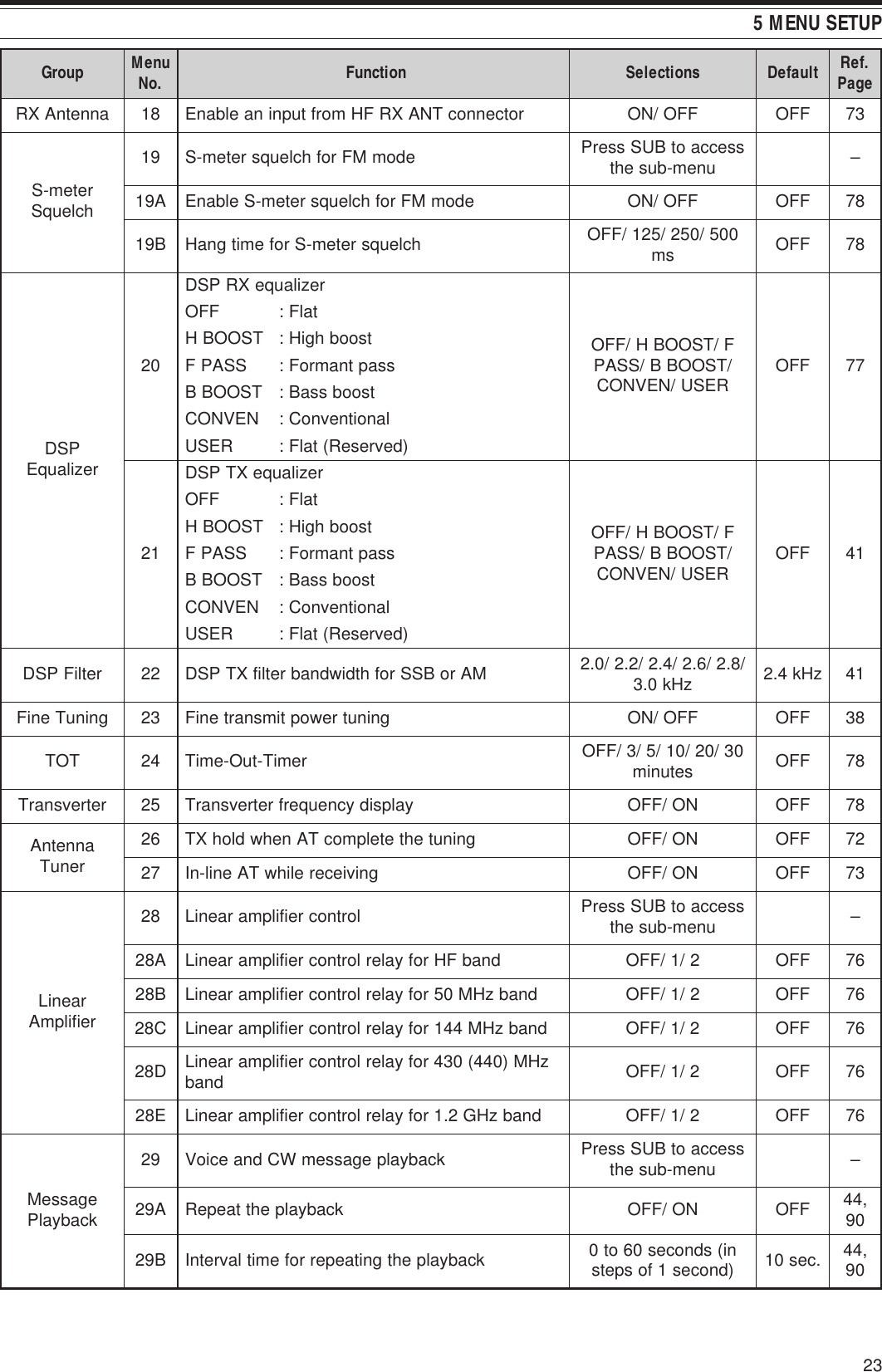
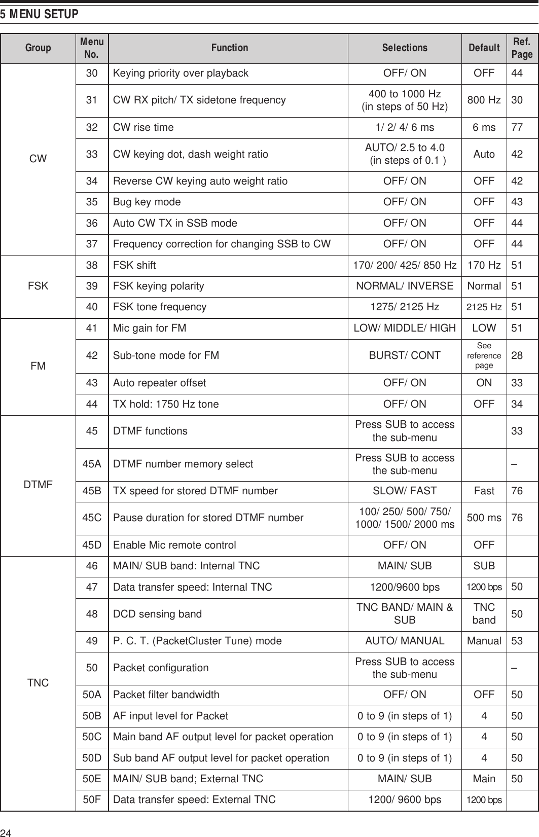
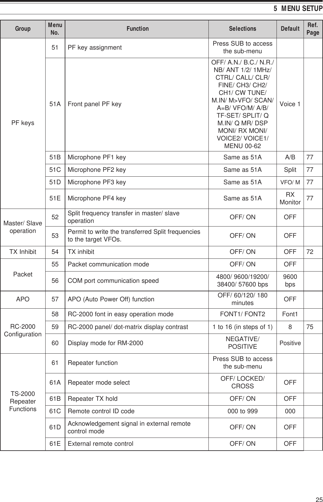
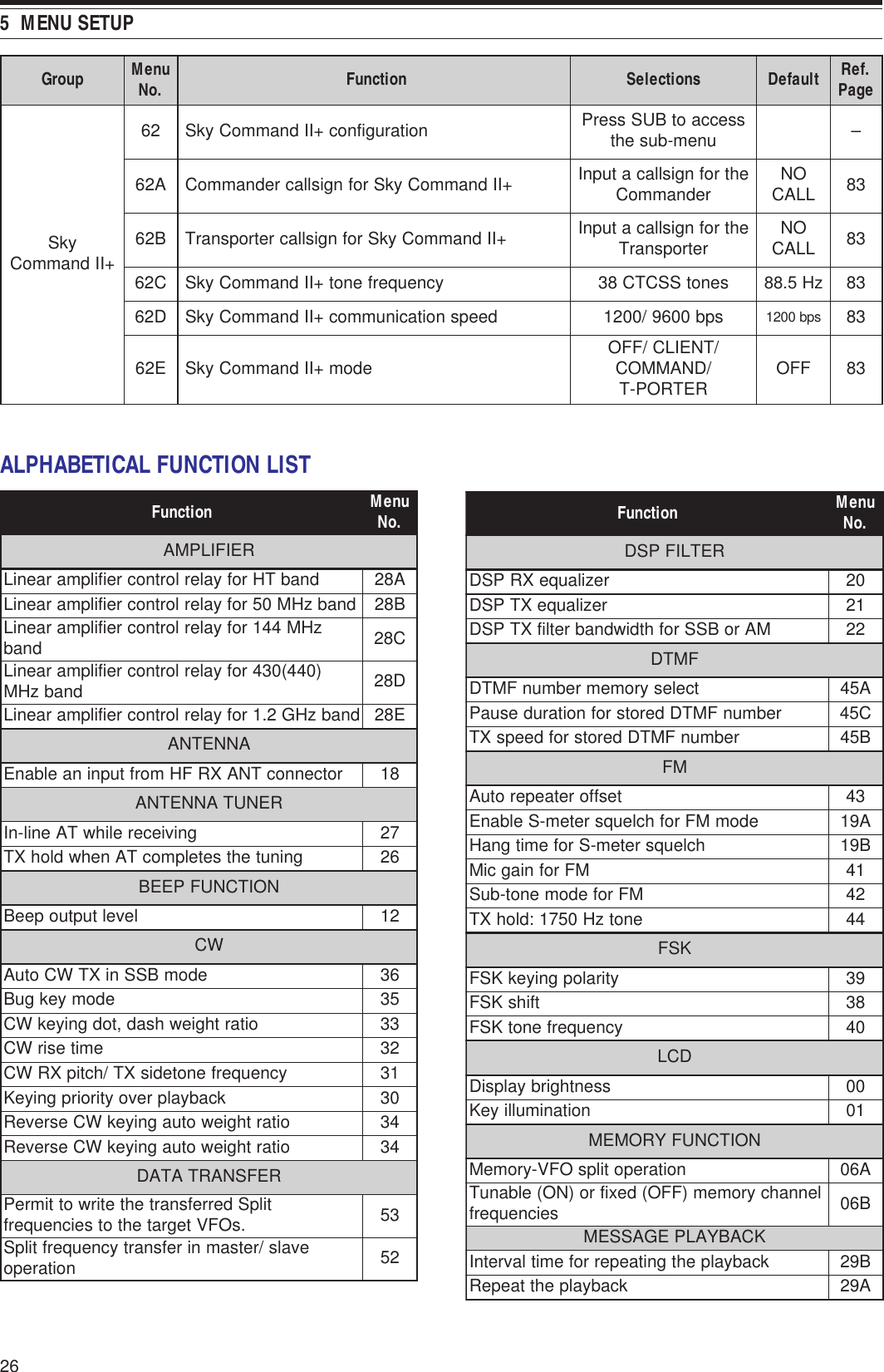
![21MENU SETUPWHAT IS A MENU?Many functions on this transceiver are selected orconfigured via a software-controlled Menu, ratherthan through the physical controls of the transceiver.Once familiar with the Menu system, you willappreciate the versatility it offers. You can customizethe various timings, settings, and programmingfunctions on this transceiver to meet your needswithout using many controls and switches.MENU A/ MENU BThis transceiver has two menus: Menu A andMenu B. These menus contain identical functionsand can be configured independently. Thetransceiver, therefore, allows you to switch betweentwo different environments quickly and easily. Forexample, you can configure Menu A with one set oftransmit signal characteristics, DSP settings,programmable keys, frequency steps, etc., andMenu B with a completely different set. By switchingfrom Menu A to Menu B, you can instantly changethe Menu configuration and button assignment to suityour current operating style. Or, two operators mayshare a single transceiver by dedicating one Menu toeach operator. Both operators can always enjoytheir own configuration.MENU ACCESS1Press [MENU].• The Menu No. and setting appear on the maindot-matrix display, and the explanation of themenu appears on the sub dot-matrix display.2Press [A/B] to select Menu A or Menu B.• “A” or “B” appears, indicating which Menu isselected.3Turn the MULTI/ CH control to select the desiredMenu No.• Each time you change the Menu No., adifferent scrolling message appears on the subdot-matrix display, describing the Menu No.• You will see “PUSH SUB” if there are sub-menus in the Menu No. Pressing [SUB]allows you to select from among the sub-menus. Press [MAIN] to exit the sub-menuselection.4Press [+], [–], Mic [UP], or Mic [DWN] to select aparameter.5Press [MENU] to exit Menu mode.QUICK MENUBecause the number of functions this transceiverprovides is extraordinary, there are numerous items ineach Menu. If you find accessing desired Menu Nos.to be too time consuming, use the Quick Menu tocreate your own customized, abbreviated Menu. Youcan then add those Menu Nos. which you frequentlyuse, to the Quick Menu. Copying Menu Nos. to theQuick Menu has no effect on the Menu.PROGRAMMING THE QUICK MENU1Press [MENU].2Turn the MULTI/ CH control to select the desiredMenu No.3Press QUICK MEMO [M.IN].• A star appears, indicating that the Menu itemhas been added to the Quick Menu.• To remove the item from the Quick Menu,press QUICK MEMO [M.IN] again.4Press [MENU] to exit Menu mode.Note: You cannot add the sub menu No. to the Quick Menu. Press[MAIN] to go back to the main menu No., then press QUICK MEMO[M.IN] to add the menu No. to the Quick Menu.USING THE QUICK MENU1Press [MENU].2Press [1MHz/ SEL].• “MHz” appears.3Turn the MULTI/ CH control to select the desiredQuick Menu No.4Press [+], [–], Mic [UP], or Mic [DWN] to changethe current setting for the selected Menu No.5Press [MENU] to exit Quick Menu mode.Note: If the Quick Menu has not been programmed, turning theMULTI/ CH control in step 3 causes “CHECK” to be output in Morsecode.](https://usermanual.wiki/JVC-KENWOOD/31201110/User-Guide-119445-Page-29.png)
![28BASIC COMMUNICATIONSSSB TRANSMISSIONSSB is the most commonly-used mode on the HFAmateur bands. Compared with other voice modes,SSB requires only a narrow bandwidth forcommunications. SSB also allows long distancecommunications with minimum transmit power.If necessary, refer to “OPERATING BASICS”,beginning on page 18, for details on how to receive.1Select an operating frequency.2Press [LSB/ USB/ AUTO] to select either lower orupper sideband mode.• “LSB” or “USB” appears to show whichsideband is selected.3Press [MIC/ CAR] to activate the MicrophoneGain Adjust.• The current gain level appears.4Press [SEND], or press and hold Mic [PTT].• The MAIN band LED lights red.• Refer to “VOX” {page 29} for information onautomatic TX/RX switching.5Speak into the microphone and adjust theMULTI/ CH control so that the ALC meter reflectsyour voice level but does not exceed the ALC limit.• Speak in your normal tone and level of voice.Speaking too close to the microphone or tooloudly may increase distortion and reduceintelligibility at the receiving end.• You may want to use the Speech Processor.Refer to “SPEECH PROCESSOR” {page 40}for details.6Press [SEND] or release Mic [PTT] to return toreceive mode.• The MAIN band LED lights green or turns off,depending on the MAIN SQL setting.7Press [MIC/ CAR] to quit the Microphone GainAdjust.Refer to “COMMUNICATING AIDS”, beginning onpage 37, for information on additional usefuloperation functions.FM TRANSMISSIONFM is a common mode for communicating on VHF orUHF frequencies. Many amateur radio operators usetheir portable radios and mobile transceivers in FMmode. You can also utilize repeaters to reach yourfriends when they are outside your antennacoverage. Although FM requires a wider bandwidthwhen compared to SSB or AM mode, it has the finestaudio quality among these modes. When combinedwith the full-quieting aspect of FM signals, whichsuppress background noise on the frequency, FM canbe the best method for maintaining regular scheduleswith your local friends.If necessary, refer to “OPERATING BASICS”,beginning on page 18, for details on how to receive.1Select an operating frequency.2Press [FM/ AM/ NAR] to select FM mode.• “FM” appears.3Press [SEND], or press and hold Mic [PTT].• The MAIN band LED lights red.• Refer to “VOX” {page 39} for information onautomatic TX/RX switching.4Speak into the microphone in your normal toneand level of voice.• Speaking too close to the microphone or tooloudly may increase distortion and reduceintelligibility at the receiving end.• You can switch the Microphone Gain for FMbetween low, medium, and high by using MenuNo. 41. Low is usually appropriate; however,select high if other stations report that yourmodulation is weak. The MULTI/ CH controlhas no effect in FM mode.5Press [SEND] or release Mic [PTT] to return toreceive mode.• The MAIN band LED lights green or turns off,depending on the MAIN SQL setting.Refer to “COMMUNICATING AIDS”, beginning onpage 37, for additional information on usefuloperation functions.](https://usermanual.wiki/JVC-KENWOOD/31201110/User-Guide-119445-Page-36.png)
![29 6 BASIC COMMUNICATIONSNARROW BANDWIDTH FOR FMWhen operating in FM mode, you can select wide ornarrow bandwidth operation. The table below showsthe RX IF filter bandwidth and TX deviationcombination for each operating mode. Thebandwidth selection is crucial to avoid audio distortionor insufficient intelligibility that the other station willencounter.1K-type: Main transceiver only.All E-types: Main transceiver and sub-receiver.1Press [FM/ AM/ NAR] to select FM mode.2Press [FUNC], [FM/ AM/ NAR] to toggle theselection between Wide and Narrow.• “FM” or “FMN” appears to indicate whichbandwidth is selected.NARROW BANDWIDTH FOR AMWhen receiving AM on the main transceiver, you canfurther decrease the bandwidth to eliminateinterferences. However, the TX deviation of AM is notaffected by this selection.1Press [FM/ AM/ NAR] to select AM mode on themain transceiver.2Press [FUNC], [FM/ AM/ NAR] to toggle theselection between Normal and Narrow.• “AM” or “AMN” appears to indicate which IFbandwidth is selected for the main transceiver.AM TRANSMISSIONEach mode used on the HF Amateur bands has itsown advantages. Although long distance DXcontacts may be less common while using AM, thesuperior audio quality characteristic of AM operationis one reason why some hams prefer this mode.When looking for others operating on AM, check thefollowing frequencies first:3885 kHz, 7290 kHz, 14286 kHz, 21390 kHz, and29000 ~ 29200 kHzIf necessary, refer to “OPERATING BASICS”,beginning on page 18, for details on how to receive.1Select an operating frequency.2Press [FM/ AM/ NAR] to select AM mode.• “AM” appears.3Press [MIC/ CAR] to activate the MicrophoneGain Adjust.• The current gain level appears.4Press [SEND], or press and hold Mic [PTT].• The MAIN band LED lights red.• Refer to “VOX” {page 39} for information onautomatic TX/RX switching.5Speak into the microphone and adjust theMULTI/ CH control so that the calibrated powermeter slightly reflects your voice level.• Speak in your normal tone and level of voice.Speaking too close to the microphone or tooloudly may increase distortion and reduceintelligibility at the receiving end.• You may want to use the Speech Processor.Refer to “SPEECH PROCESSOR” {page 40}for details.6Press [SEND] or release Mic [PTT] to return toreceive mode.• The MAIN band LED lights green or turns off,depending on the MAIN SQL setting.7Press [MIC/ CAR] to quit the Microphone GainAdjust.Refer to “COMMUNICATING AIDS”, beginning onpage 37, for information on additional usefuloperation functions.Note: If necessary, adjust the carrier level before speaking into themicrophone. Press [FUNC], [MIC/ CAR] to enter the adjustmentmode. While transmitting only carrier signals, turn the MULTI/ CHcontrol so that the ALC meter just begins to indicate. Press [FUNC],[MIC/ CAR] again to complete the adjustment.edoM retliFFIXR noitaiveDXTMFediWediWNMFworraN1worraN](https://usermanual.wiki/JVC-KENWOOD/31201110/User-Guide-119445-Page-37.png)
![306 BASIC COMMUNICATIONSCW TRANSMISSIONCW operators know that this mode is very reliablewhen communicating under worst conditions. It maybe true that newer digital modes rival CW as beingequally as useful in poor conditions. These modes,however, do not have the long history of service northe simplicity that CW provides.This transceiver has a built-in electronic keyer thatsupports a variety of functions. For details on usingthese functions, refer to “ELECTRONIC KEYER”{page 42}.If necessary, refer to “OPERATING BASICS”,beginning on page 18, for details on how to receive.1Select the operating frequency.2Press [CW/ FSK/ REV] to select CW mode.• “CW” appears.• To precisely tune in another station, use AutoZero-beat. Refer to “AUTO ZERO-BEAT”{below}.3Press [SEND].• The MAIN band LED lights red.• Refer to “CW BREAK-IN” {page 42} forinformation on automatic TX/ RX switching.4Begin sending.• As you transmit, you should hear a sidetonethat lets you monitor your own transmission.Refer to “TX SIDETONE/ RX PITCHFREQUENCY” {below}.5Press [SEND] to return to receive mode.• The MAIN band LED lights green or turns off,depending on the MAIN SQL setting.Note: You may adjust the carrier level when necessary. Press[FUNC], [MIC/ CAR] to enter the adjustment mode. With the keydown, turn the MULTI/ CH control so that the ALC meter reads withinthe ALC zone but does not exceed the upper ALC zone limit. Press[FUNC], [MIC/ CAR] again to complete the adjustment.AUTO ZERO-BEATUse Auto Zero-beat before transmitting to tune in aCW station. Auto Zero-beat automatically and exactlymatches your transmit frequency with the station youare receiving. Neglecting to do this will reduce yourchances of being heard by the other station.1Press [FUNC], [RIT/ CW TUNE] to start AutoZero-beat.• “CW TUNE” appears.• Your transmit frequency automatically changesso that the pitch of the received signal exactlymatches the TX sidetone/ RX pitch frequencythat you have selected. Refer to “TXSIDETONE/ RX PITCH FREQUENCY” {below}.• When matching is completed, “CW TUNE”disappears.• If matching is unsuccessful, the previousfrequency is restored.2To quit Auto Zero-beat, press [FUNC],[RIT/ CW TUNE] or [CLR].Note:◆You cannot start Auto Zero-beat if you have selected 1.0 kHzor wider for the DSP filter bandwidth.◆When using Auto Zero-beat, the matching error is within±50 Hz in most cases.◆Auto Zero-beat may fail if the keying speed of the targetstation is too slow or when some interference is present.◆When RIT function is ON, only RIT frequencies changes tomake Auto Zero-beat adjustment.TX SIDETONE/ RX PITCH FREQUENCYAs you send CW, you will hear tones from thetransceiver speaker. These are called transmit (TX)sidetones. Listening to these tones, you can monitorwhat you are transmitting. You may also use thetones to ensure that your key contacts are closing,the keyer is functioning, or to practice sending withoutactually putting a signal on the air.Receive pitch refers to the frequency of CW that youhear after tuning in a CW station.On this transceiver, the frequency of the sidetone andreceive pitch are equal and selectable. Access MenuNo. 31 to select the frequency that is mostcomfortable for you. The selectable range is from400 Hz to 1000 Hz in steps of 50 Hz.To change the volume of the TX sidetone, accessMenu No. 13. The selections range from 1 to 9 andOFF.Note: The position of the MAIN AF and SUB AF controls does notaffect the volume of the TX sidetone.](https://usermanual.wiki/JVC-KENWOOD/31201110/User-Guide-119445-Page-38.png)
![31ENHANCED COMMUNICATIONSSPLIT-FREQUENCY OPERATIONUsually you can communicate with other stationsusing a single frequency for receiving andtransmitting. In this case, you select only onefrequency on either VFO A or VFO B. However, thereare cases where you must select one frequency forreceiving and a different frequency for transmitting.This requires the use of two VFOs. This is referred toas “split-frequency operation”. One typical casewhich requires this type of operation is when you usean FM repeater {page 22}. Another typical case iswhen you call a rare DX station.When a rare or desirable DX station is heard, thatoperator may immediately get many simultaneousresponses. Often, such a station is lost under thenoise and confusion of many calling stations. If youfind that you are suddenly being called by manyoperators, it is your responsibility to control thesituation. You may announce that you will be“listening up 5 (kHz, from your present transmitfrequency)”, or “listening down between 5 and 10(kHz)”.1Press [MAIN], [A/B] to select VFO A or VFO B onthe main transceier.•“tA” or “tB” appears to show which VFO isselected.2Select an operating frequency.• The frequency selected at this point will beused for transmitting.• To copy the selected VFO frequency to theother VFO, press [A=B].3Press [A/B] to select the other VFO.4Select an operating frequency.• The frequency selected on this VFO will beused for receiving.5Press [SPLIT].• “SPLIT” appears.• Each press of [A/B] reverses the receive andtransmit frequencies.6To quit split-frequency operation, press [SPLIT]again.• “SPLIT” disappears.If you access Menu No. 06A and select “ON”, you canrecall a memory channel to use for either receiving ortransmitting. For more information, refer to “Memory-VFO Split Operation” {page 60} under “MEMORYFEATURES”.Note: You cannot perform SPLIT operation on the sub-receiver; ithas only one VFO.TF-SET (TRANSMIT FREQUENCY SET)TF-SET allows you to temporarily switch yourtransmit frequency and receive frequency. Cancelingthis function immediately restores the originaltransmit and receive frequencies. By activating TF-SET, you can listen on your transmit frequency, andchange it while listening. This allows you to checkwhether or not the newly selected transmit frequencyis free of interference.1Configure split-frequency operation as explainedin the previous section.2Press and hold [TF-SET].3While holding down [TF-SET], change theoperating frequency by turning the Tuning controlor by pressing Mic [UP]/ [DWN].• The transceiver receives on the frequency thatyou select, but the frequency shown on thesub-display stays unchanged.4Release [TF-SET].• You are now receiving again on your originalreceive frequency.Successfully contacting a DX station in a pileup oftendepends on making a well-timed call on a clearfrequency. That is, it is important to select a relativelyclear transmit frequency and to transmit at the exactinstant when the DX station is listening but themajority of the group aren’t transmitting. Switch yourreceive and transmit frequencies by using TF-SETand listen. You will soon learn the rhythm of the DXstation and the pileup. The more proficient youbecome at using this function, the more DX stationsyou will contact.Note:◆If you press [FUNC], [ATT/ F LOCK] to lock the operatingfrequency before using TF-SET, pressing an incorrect buttonby mistake retains the original receive frequency.◆TF-SET is disabled while transmitting.◆If you have recalled a memory channel (excluding CH 290 to299), you cannot change the recalled frequency using theTuning control.◆To enable the Tuning control, access Menu No. 06B andselect “ON”. Pressing Mic [UP]/ [DWN] after recalling amemory channel changes the memory channels.◆An RIT frequency shift is not added; however, an XITfrequency shift is added to the transmit frequency.](https://usermanual.wiki/JVC-KENWOOD/31201110/User-Guide-119445-Page-39.png)
![327 ENHANCED COMMUNICATIONSFM REPEATER OPERATIONWhen using FM mode, you may access a repeater toenjoy long distance communications. Repeaters,which are often installed and maintained by radioclubs, are usually located on mountain tops or otherelevated locations. Generally they operate at higherERP (Effective Radiated Power) than a typical station.This combination of elevation and high ERP allowscommunications in FM over much greater distancesthan FM communications without using repeaters.Most repeaters use a receive and transmit frequencypair with an offset. In addition, some repeaters mustreceive a tone from the transceiver before it allowsaccess. Repeaters are available on the 29, 50, 144,430 (440) MHz, and 1.2 GHz bands (TS-2000/TS-B2000 Optional). For further information,including repeater frequencies, consult your localrepeater reference.This transceiver provides the following three methodsfor programming two separate frequencies:• Using the Split-Frequency function {page 31}• Programming an offset (29, 50, 144,430 (440) MHz and 1.2 GHz bands)• Storing in a Split-Frequency channel {page 59}Note:◆When programming two separate frequencies using two VFOs,be sure to select FM mode on both VFOs.◆When operating through a repeater, over deviation caused byspeaking too loudly into the microphone can cause your signal to“talk-off” (break up) through the repeater.PROGRAMMING AN OFFSETWhen using the 29, 50, 144, 430 (440) MHz or1.2 GHz band (TS-2000/ TS-B2000 Optional),selecting a single frequency and an offset is anothermethod for programming two separate frequencies.Unlike the Split-Frequency function, this methodrequires only a single VFO.Note: If you store offset settings in a memory channel, you need notreprogram each time. Refer to “MEMORY FEATURES” {page 58}.29.520 MHz88.5 Hz29.520 MHz88.5 Hz29.620 MHz29.620 MHz■Selecting an Offset Direction1Select a receive frequency.2Press [0/ SHIFT/ OFFSET] to switch the offsetdirection.• Select whether the transmit frequency willbe higher (+) or lower (–) than the receivefrequency.• “+” or “–” appears to indicate which offsetdirection is selected.• To program –7.6 MHz (430 MHz) or –6.0MHz (1.2 GHz) offset on all E-types,repeatedly press [0/ SHIFT/ OFFSET] until“=” appears.If the offset transmit frequency falls outside theallowable range, transmitting is inhibited. Use oneof the following methods to bring the transmitfrequency within the band limits:• Move the receive frequency further inside theband.• Change the offset direction.Note:◆You can only change the offset direction while in FM mode.◆While using an odd-split memory channel for transmitting,you cannot change the offset direction.■Selecting an Offset FrequencyTo access a repeater which requires an odd-splitfrequency pair, change the offset frequency fromthe default which is used by most repeaters. Thedefault offset frequencies are as follows.As for 29 and 50 MHz bands, the default offset isset to 0 MHz (Simplex). Program the desiredoffset frequency for these bands.1Press [FUNC], [0/ SHIFT/ OFFSET].2Turn the MULTI/ CH control to select theappropriate offset frequency.• The selectable range is from 0.00 MHz to59.95 MHz in steps of 50 kHz.3Press [FUNC], [0/ SHIFT/ OFFSET] again tocomplete the setting.All E-types only: If you have selected “ =” for the offsetdirection, you cannot change the default (–7.6 MHz or –6.0 MHz).dnaB dna.S.U srehtO eporuEzHM441 ±zHk006zHM)044(034 ±zHM0.5 ±zHM6.1 zHM6.7-).tpO(zHG2.1 ±zHM0.21 ±zHM0.53 zHM0.6-](https://usermanual.wiki/JVC-KENWOOD/31201110/User-Guide-119445-Page-40.png)
![33 7 ENHANCED COMMUNICATIONSTRANSMITTING A TONESome FM repeaters require the transceiver totransmit a subaudible tone to prevent other repeaterson the same frequency from locking each other up.The required tone frequency differs among repeaters.Repeaters also differ in their requirements for eithercontinuous or burst tones. For the appropriateselections for your accessible repeaters, consult yourlocal repeater reference.After completing the tone settings, pressing [SEND]or pressing and holding Mic [PTT] causes thetransceiver to transmit the selected tone. If you haveselected a 1750 Hz tone, press [4/ TONE/ SEL] totransmit the tone without pressing [PTT].Note: If you store tone settings in a memory channel, you need notreprogram each time. Refer to “MEMORY FEATURES” {page 58}.■Activating the Tone Function1Confirm that FM mode has been selected onthe VFO(s).• When using two VFOs, you must select FMmode on both VFOs.2Press [4/ TONE/ SEL] to switch the Tonefunction ON (or OFF).• “T” appears when the function is ON.Note:◆You cannot use the Tone function with the CTCSS or DCSfunctions.◆You need to activate the Tone function only when selectingone of the 38 standard frequencies. The selection you makehere will not affect the transmission of the 1750 Hz tone.■Selecting a Tone Frequency1Press [FUNC], [4/ TONE/ SEL].• The current tone frequency appears. Thedefault is 88.5 Hz.2Turn the MULTI/ CH control to select theappropriate tone frequency.• The available tone frequencies are listed inthe following table.3Press [FUNC], [4/ TONE/ SEL] to complete thesetting.Note:◆Use Nos. 01 to 39 shown in the table above when selectingtone frequencies via Computer Control {page XX}.◆You can select a tone frequency independent of a CTCSSfrequency.■Selecting Continuous or BurstAccess Menu No. 42 to select “Continuous” or“Burst”. With Continuous selected, the transceiversends the tone continuously during thetransmission. With Burst selected, the transceiversends a 500 ms tone each time transmissionstarts. When using the 144, 430 (440) MHz, or1.2 GHz band, continuous tones are alwaystransmitted, regardless of the selection.■Transmitting a 1750 Hz ToneMost repeaters in Europe require transceivers totransmit a 1750 Hz tone. With 1750 Hz toneselected, pressing [4/ TONE/ SEL] causes thetransceiver to transmit the 1750 Hz tone.Releasing the key ceases transmission of thecode. Some repeaters in Europe must receivecontinuous signals for a certain period of time,following a 1750 Hz tone. This transceiver iscapable of remaining in transmit mode for 2seconds after transmitting the 1750 Hz tone.Access Menu No. 44 and select “ON”..oN .qerF )zH( .oN .qerF )zH( .oN .qerF )zH( .oN .qerF )zH(100.76114.79125.631138.291209.17210.001223.141235.302304.47315.301322.641337.012400.77412.701424.151431.812507.97519.011527.651537.522605.28618.411622.261636.332704.58718.811729.761738.142805.88810.321828.371833.052905.19913.721929.971930571018.49028.131032.681](https://usermanual.wiki/JVC-KENWOOD/31201110/User-Guide-119445-Page-41.png)
![347 ENHANCED COMMUNICATIONSAUTOMATIC REPEATER OFFSETThis function automatically selects an offset direction,according to the frequency that you select on the144 MHz band. The transceiver is programmed foroffset directions as shown below. To obtain an up-to-date band plan for repeater offset direction, contactyour national Amateur Radio association.Access Menu No. 43 and switch the function ON orOFF. The default is ON.K-type (U.S.A. and Canada versions)This complies with the standard ARRL band plan.All E-types (European versions)Note:◆Automatic Repeater Offset does not function when Reverse isON. However, pressing [TF-SET] after Automatic RepeaterOffset has selected an offset (split) status, exchanges the receiveand transmit frequencies.◆If you change the offset direction by pressing [0/ SHIFT/OFFSET] when Automatic Repeater Offset is ON, the Shiftdirection on the above figure is applied when you change thefrequencies.REVERSE FUNCTIONAfter programming an offset on the 29, 50, 144, 430(440) MHz, and 1.2 GHz (Optional) band, the reversefunction exchanges a separate receive and transmitfrequency. So, while using a repeater, you canmanually check the strength of a signal that youreceive directly from the other station. If the station’ssignal is strong, both stations should move to asimplex frequency to free up the repeater.Press [TF-SET] to switch the Reverse function ON(or OFF) while the Shift function is active.• “R” appears when the Reverse function is ON.Note:◆If pressing [TF-SET] places the transmit frequency outside theallowable range, pressing Mic [PTT] will cause an error beep tosound; transmission will be inhibited.◆If pressing [TF-SET] places the receive frequency outside theallowable range, an error beep will sound and reversal will notoccur.◆Automatic Repeater Offset does not function while Reverse isON.◆You cannot switch Reverse ON or OFF while transmitting.+−−− +SSSS144.0 145.5 146.4 147.0 147.6145.1 146.0 146.6 147.4 148.0 MHzS: SimplexSSS: Simplex–144.0 146.0 MHz145.8145.6AUTOMATIC SIMPLEX CHECK (ASC)ASC functions only when you have programmed anoffset on the 29, 50, 144, 430 (440) MHz or 1.2 GHz(Optional) band. While using a repeater, ASCperiodically monitors the strength of a signal that youreceive directly from the other station. If the station’ssignal is strong enough to allow direct contact withouta repeater, the ASC indicator on the display startsblinking.Press and hold [TF-SET] for approximately 1 secondto switch the function ON.• The [R] indicator appears when the function is ON.• When direct contact is possible, the [R] indicatorblinks.• To quit the function, press [TF-SET].Note:◆Pressing Mic [PTT] causes the ASC indicator to stop blinking.◆ASC does not function if your transmit and receive frequenciesare the same (simplex operation).◆ASC does not function while scanning.◆Activating ASC while using Reverse switches Reverse OFF.◆If you recall a memory channel or the Call channel that has theReverse status ON, ASC is switched OFF.◆ASC causes received audio to be momentarily intermitted every3 seconds.TONE FREQ. ID SCANThis function scans through all tone frequencies toidentify the incoming tone frequency on a receivedsignal. You can use this function to find which tonefrequency is required by your local repeater.1Press [FUNC], [4/ TONE/ SEL].• The current tone frequency appears.2Press [SCAN/ SG. SEL] to activate the ToneFreq. ID.•When the tone frequency is identified, theidentified frequency appears and blinks.• Press [SCAN/ SG. SEL] while the identifiedfrequency is blinking, to resume scanning.• Press [FUNC], [4/ TONE/ SEL] again to quitthe function.](https://usermanual.wiki/JVC-KENWOOD/31201110/User-Guide-119445-Page-42.png)
![35 7 ENHANCED COMMUNICATONSFM CTCSS OPERATIONYou may sometimes want to hear calls only fromspecific persons. When using FM mode, theContinuous Tone Coded Squelch System (CTCSS)allows you to ignore (not hear) unwanted calls fromother persons who are using the same frequency. ACTCSS tone is subaudible and is selectable fromamong the 38 standard tone frequencies. Select thesame CTCSS tone as the other stations in yourgroup. You will not hear calls from stations other thanthose using the same CTCSS tone.Note: CTCSS does not cause your conversation to be private. Itonly relieves you from listening to unwanted conversations.1Press [A/B] to select VFO A or VFO B.•“tA” or “tB” appears to show which VFO isselected.2Select a band.3Select an operating frequency.4Press [FM/ AM/ NAR] to select FM mode.• “FM” appears.5Turn the SQL control to adjust the squelch.6Press [6/ CTCSS/ SEL] to switch the CTCSSfunction ON (or OFF).• “CT” appears when the function is ON.7Press [FUNC], [6/ CTCSS/ SEL].• The current CTCSS frequency appears. Thedefault CTCSS frequency is 88.5 Hz.<DIAGRAM 35-02>8Turn the MULTI/ CH control to select theappropriate CTCSS frequency.• The selectable CTCSS frequencies are listed inthe following table.9Press [FUNC], [6/ CTCSS/ SEL] to complete thesetting.You will hear calls only when the selected tone isreceived. To answer the call, press [SEND] or pressand hold Mic [PTT], then speak into the microphone.Skip steps 7 and 8 if you have already programmedthe appropriate CTCSS frequency.Note:◆When using split-frequency operation, select FM mode onboth VFOs to use CTCSS.◆Use Nos. 01 to 38 shown in the table above when selectingCTCSS frequencies via Computer Control {page XX}.◆You can select a CTCSS frequency independent of a tonefrequency.◆You cannot use the CTCSS function with the Tone or DCSfunctions.CTCSS FREQ. ID SCANThis function scans through all CTCSS frequencies toidentify the incoming CTCSS frequency on a receivedsignal. You may find this useful when you cannotrecall the CTCSS frequency that the other persons inyour group are using.1Press [FUNC], [6/ CTCSS/ SEL].• The current CTCSS frequency appears.2Press [SCAN/ SG. SEL] to activate the CTCSSFreq. ID scan.•“C T” blinks and every CTCSS tone frequencyis scanned. When the CTCSS frequency isidentified, the transceiver stops scanning andthe identified frequency is displayed.<DIAGRAM 35-03>• Press [SCAN/ SG. SEL] to resume scanning.• Press [FUNC], [6/ CTCSS/ SEL] to quit thescanning.Note: Received signals are audible while scanning is in progress..oN .qerF )zH( .oN .qerF )zH( .oN .qerF )zH( .oN .qerF )zH(100.76114.79125.631138.291209.17210.001223.141235.302304.47315.301322.641337.012400.77412.701424.151431.812507.97519.011527.651537.522605.28618.411622.261636.332704.58718.811729.761738.142805.88810.321828.371833.052905.19913.721929.971018.49028.131032.681](https://usermanual.wiki/JVC-KENWOOD/31201110/User-Guide-119445-Page-43.png)
![367 ENHANCED COMMUNICATIONSFM DCS OPERATIONDigital Code Squelch (DCS) is another FMapplication which allows you to ignore (not hear)unwanted calls. It functions the same way asCTCSS. The only differences are the encode/decode method and the number of selectable codes.For DCS, you can select from 104 different codeslisted in the table below.1Press [A/B] to select VFO A or VFO B.•“tA” or “tB” appears to show which VFO isselected.2Select a band.3Select an operating frequency.4Press [FM/ AM/ NAR] to select FM mode.• “FM” appears.5Turn the SQL control to adjust the squelch.6Press [•/ DCS/SEL] to switch the DCS functionON (or OFF).• “DCS” appears when the function is ON.7Press [FUNC], [•/ DCS/SEL].• The current DCS code appears and blinks.The default is 023.8Turn the MULTI/ CH control to select theappropriate DCS code.• The available DCS codes are listed in thefollowing table.9Press [FUNC], [•/ DCS/SEL] again to completethe setting.320560231502552133314564216137520170431212162233324664426237620270341322362343134305726437130370541522562643234605136347230470251622662153544615236457630411551342172653644325456340511651442472463254625266740611261542603563454235466150221561642113173554645307350521271152513114264565217450131471252523214464606327You will hear calls only when the selected code isreceived. To answer the call, press [SEND] or pressand hold Mic [PTT], then speak into the microphone.Skip steps 7 to 9 if you have already programmed theappropriate DCS code.Note: You cannot use DCS with the Tone or CTCSS functions.DCS CODE ID SCANThis function scans through all DCS codes to identifythe incoming DCS code on a received signal. Youmay find this useful when you cannot recall the DCScode that the other persons in your group are using.1Press [FUNC], [•/ DCS/SEL].• The current DCS code appears.2Press [SCAN/ SG.SEL] to activate the DCS CodeID scan.•“DCS” blinks and every DCS code is scanned.When the DCS code is identified, thetransceiver stops scanning and the identifiedDCS ID is displayed.• Press [SCAN/ SG.SEL] to resume scanning.• Press [FUNC], [•/ DCS/SEL] to quit scanning.Note: Received signals are audible while scanning is in progress.](https://usermanual.wiki/JVC-KENWOOD/31201110/User-Guide-119445-Page-44.png)
![37 COMMUNICATING AIDSRECEIVINGSELECTING YOUR FREQUENCYIn addition to turning the Tuning control or pressingMic [UP]/[DWN], there are several other ways toselect your frequency. This section describesadditional methods of frequency selection that maysave your time and effort.■Direct Frequency EntryWhen the desired frequency is far removed fromthe current frequency, directly entering afrequency from the numeric keypad is usually thefastest method.1Press [ENT].• “- - - . - - - . - - ” appears.2Press the numeric keys ([0] to [9]) to enteryour desired frequency.• Pressing [ENT] fills the remaining digits (thedigits you did not enter) with 0 andcompletes entry.• To select 1.85 MHz for example, press [0],[0], [0], [1], [8], [5], then press [ENT] tocomplete the input (7 key strokes).• To shorten the key strokes, you can alsouse [•] as MHz. Press [1], [•] (MHz), [8],[5], then press [ENT] to complete the input(5 key strokes).• Pressing [CLR] cancels the entry andrestores the current VFO frequency.Note:◆You can enter the frequency in the range of 30.00 kHz to1299.99999 MHz.◆Attempting to enter a frequency that is outside theselectable frequency range causes an alarm to sound.The entered frequency is rejected.◆When the entered frequency does not meet the currentVFO frequency step size requirement, the nearestavailable frequency is automatically selected (Sub-receiver). The nearest available frequency isautomatically selected after the entered frequency ischanged (Main transceiver).◆When the 10 Hz digit (last displayed digit) is entered, thedigit 0 is automatically entered for the 1 Hz digit, andfrequency entry is completed. The 1 Hz digit is notdisplayed.◆When an entered frequency is accepted, RIT or XIT will beswitched OFF, but the RIT or XIT offset frequency is notcleared.◆After recalling memory channels 290 to 299 that haveStart and End frequencies stored, the receive frequencycan be changed by using Direct Frequency Entry withinthe programmed range.■Using 1 MHz StepsPressing [+]/ [–] on the front panel changesAmateur bands. You can also use the MULTI/ CHcontrol to change the operating frequency in stepsof 1 MHz.1Press [1MHz/ SEL].• “MHz” appears.2Turn the MULTI/ CH control.• Clockwise increases the frequency, counter-clockwise decreases the frequency.3Press [1MHz/ SEL] to exit the function.• “MHz” disappears.If you prefer to change the frequency in steps of100 kHz or 500 kHz steps rather than 1 MHz,press [FUNC], [1MHz/ SEL] then turn theMULTI/ CH control to select 100 kHz or 500 kHz.Note: Even if 100 kHz or 500 kHz is selected for the [1MHz] key,the MHz icon appears.■Quick QSYTo move up or down the frequency quickly, use theMULTI/ CH control. Turning this control changesthe operating frequency in steps of 5 kHz for SSB/CW/ FSK and 10 kHz for FM/ AM (below 60 MHz).• If you want to change the default frequencystep size, press [FUNC], [9/ FINE/ STEP].Select 5 kHz, 6.25 kHz, 10 kHz, 12.5 kHz,15 kHz, 20 kHz, 25 kHz, 30 kHz, 50 kHz or100 kHz for FM/ AM, and 1 kHz, 2.5 kHz,5 kHz, or 10 kHz for the other modes. Thedefault step size is 5 kHz for SSB/ CW/ FSK/AM and 10 kHz for FM (below 60 MHz).• When changing the operating frequency byusing the MULTI/ CH control, frequencies arerounded such that new frequencies aremultiples of the frequency step size. To cancelthis function, access Menu No. 04 and selectOFF (default is ON).• Within the AM broadcast band, the step sizeautomatically defaults to the frequency stepvalue in Menu No. 5. This step size can beswitched between 9 kHz (ON) and 5 kHz (OFF)via Menu No. 05.Note: The programmed frequency step size for the MULTI/ CHcontrol is stored independently for the HF/ 50 MHz, 144 MHz,430 (440) MHz and 1.2 GHz bands (Main transceiver). You canalso set a different frequency step size for SSB/ CW/ FSK, AM,and FM modes. The sub-receiver also stores the independentfrequency step size for 118 MHz (K-type only), 144 MHz,300MHz (K-type only), and 430 (440) MHz bands. You can alsoset a different frequency step size for FM and AM.](https://usermanual.wiki/JVC-KENWOOD/31201110/User-Guide-119445-Page-45.png)
![38 8 COMMUNICATING AIDS■Fine TuningThe default step value when turning the Tuningcontrol to change the frequency is 10 Hz for SSB,CW, and FSK modes, and 100 Hz for FM and AMmodes. However, you can change the step size to1 Hz for SSB, CW, and FSK modes, and 10 Hz forFM and AM modes.1Press [FINE].• “FINE” appears.2Turn the Tuning control to select the exactfrequency.3To quit the function, press [9/ FINE/ STEP]again.• “FINE” disappears.Note:◆Fine Tuning works only on the main transceiver.◆If Menu No. 03 is ON, you cannot perform fine tuning in FMmode for all bands and AM mode for the 144 MHz/ 430(440) MHz/ 1.2 GHz (Optional) bands.■Equalizing VFO Frequencies (A=B)This function allows you to copy the frequency andmodulation mode of the active VFO to the inactiveVFO.1Select the frequency and mode on VFO A orVFO B.2Press [A=B].• The frequency and mode selected in step 1are copied to the inactive VFO.3Press [A/B] to confirm that the frequency wascopied.RIT (RECEIVE INCREMENTAL TUNING)RIT provides the ability to change your receivefrequency by ±20.00 kHz in steps of 10 Hz withoutchanging your transmit frequency. If the Fine Tuning([FINE/ STEP]) function is ON, the step size becomes1 Hz. RIT works equally well with all modulationmodes and while using VFO or Memory Recall mode.1Press [RIT].•“RIT” and the RIT offset appear.2If required, press [CLEAR] to reset the RIT offsetto 0.3Turn the RIT/ SUB control to change your receivefrequency.4To turn off RIT, press [RIT/ CW TUNE].• The receive frequency is returned to thefrequency that was selected prior to step 1.Note:◆RIT works only on the main transceiver.◆When storing the frequency in Memory channel with RIT functionON, RIT offset frequency is added or subtracted to/ from the VFOfrequency. Then the calculated data is stored in the Memorychannel.AGC (AUTOMATIC GAIN CONTROL)When using a mode other than FM, AGC selects thetime constant for the automatic gain control circuit.Selecting a slow time constant will cause the receivergain and S-meter readings to react slowly to largeinput changes. A fast time constant causes thereceiver gain and the S-meter to react quickly tochanges in the input signal. A fast AGC setting isparticularly useful in the following situations:• Tuning rapidly• Receiving weak signals• Receiving high-speed CWUnlike other transceivers, the TS-2000’s digital AGCcircuit allows you to adjust the time constant fromslow to fast in 20 steps, where 1 is the slowest and20 is the fastest. Furthermore, you can switch theAGC OFF if you desire.For your convenience, the following default AGC timeconstant has already been programmed.SSB: Level 7 CW: Level 12FSK: Level 14 AM: Level 5To change the default time constant:1Press [8/ AGC/OFF].• The AGC time constant scale appears on thesub dot-matrix display.2To select a slower time constant, turn theMULTI/ CH control counterclockwise. The barindicator moves from F(ast) to S(low). To select afaster time constant, turn the MULTI/ CH controlclockwise. The bar indicator moves from S(low) toF(ast).3If you want to turn the AGC OFF, press [FUNC],[8/ AGC/OFF].Note: You cannot adjust the AGC time constant on the sub-receiver.](https://usermanual.wiki/JVC-KENWOOD/31201110/User-Guide-119445-Page-46.png)
![39 8 COMMUNICATING AIDSTRANSMITTINGVOX (VOICE-OPERATED TRANSMIT)VOX eliminates the necessity of manually switchingto the transmit mode each time you want to transmit.The transceiver automatically switches to transmitmode when the VOX circuitry senses that you havebegun speaking into the microphone.When using VOX, develop the habit of pausingbetween thoughts to allow the transceiver to dropback to receive mode briefly. You will then hear ifanybody wants to interrupt, plus you will have a shortperiod to gather your thoughts before speaking again.Your listeners will appreciate your consideration aswell as respect your more articulate conversation.VOX can be switched ON and OFF independently forCW and the other modes, excluding FSK.Press [VOX/ LEVEL] to toggle VOX ON and OFF.• The VOX LED lights.■Microphone Input LevelTo enjoy the VOX function, take the time toproperly adjust the gain of the VOX circuit. Thislevel controls the capability of the VOX circuit todetect the presence or absence of your voice. InCW mode, this level cannot be adjusted.1Select USB, LSB, FM, or AM mode.2Press [VOX/ LEVEL] to switch the VOXfunction ON.• The VOX LED lights.3Press [FUNC], [VOX/ LEVEL].• The current VOX gain appears on the subdot-matrix display.4 While speaking into the microphone using yournormal tone of voice, adjust the setting (defaultis 4) using the MULTI/ CH control until thetransceiver reliably switches to transmit modeeach time you speak.• The selectable gain range is from 0 to 9.• The setting should not allow backgroundnoise to switch the transceiver to transmitmode.Note: The VOX gain level can be adjusted even if VOX isswitched OFF or while you are transmitting.■Delay TimeIf the transceiver returns to receive mode tooquickly after you stop speaking, your final wordmay not be transmitted. To avoid this, select anappropriate delay time that allows all of yourwords to be transmitted without an overly longdelay after you stop speaking.1Select USB, LSB, FM, or AM mode.2Press [VOX/ LEVEL] to switch the VOXfunction ON.3Press [FUNC], [KEY/ DELAY].• The current setting appears on the sub dot-matrix display. The default is 50.4While speaking into the microphone using yournormal tone of voice, adjust the MULTI/ CHcontrol such that the transceiver switches toreceive mode after you have stopped talking.• The selectable range is from 5 to 100(150 ms to 3000 ms) in steps of 5, or OFF.5Press [FUNC], [KEY/ DELAY] to set the VOXdelay.](https://usermanual.wiki/JVC-KENWOOD/31201110/User-Guide-119445-Page-47.png)
![40 8 COMMUNICATING AIDSSPEECH PROCESSORThe Speech Processor levels out large fluctuations inyour voice while you speak. When using SSB, FM, orAM mode, this leveling action effectively raises theaverage transmit output power, resulting in a moreunderstandable signal. The amount of voicecompression is fully adjustable. You will notice thatusing the Speech Processor makes it easier to beheard by distant stations.1Select USB, LSB, FM, or AM mode.2Press [PROC/ LEVEL] to switch the SpeechProcessor ON.• The PROC LED lights.3Press [FUNC], [PROC/ LEVEL] to enter theSpeech Processor input level adjustment mode.4As you speak into the microphone, turn theMULTI/ CH control so that the compression meterindicates that the compression level is around 10dB while you speak.• Using higher compression will not improve yoursignal clarity or apparent signal strength.Excessively compressed signals are moredifficult to understand due to distortion and areless pleasant to hear than signals with lesscompression.5Press [FUNC], [PROC/ LEVEL] to exit the SpeechProcessor input level adjustment.6Press [MIC/ CAR] to enter the Microphone GainAdjustment.• As you speak into the microphone, turn theMULTI/ CH control so that the ALC meterreflects accroding to your voice level but doesnot exceed the ALC limit. Press [MIC/ CAR] toexit when you finish the adjustment.Transmit powerTransmit powerTimeTimeSpeech Processor OFFSpeech Processor ONXIT (TRANSMIT INCREMENTAL TUNING)Similar to RIT, XIT provides the ability to change yourtransmit frequency by ±20.00 kHz in steps of 10 Hzwithout changing your receive frequency. If the FineTuning ([FINE]) function is ON, the step size is 1 Hz.1Press [XIT/ ALT].• “XIT” and the XIT offset appear.2If required, press [CLEAR] to reset the XIT offsetto 0.3Turn the RIT/ SUB control to change your transmitfrequency.4To turn XIT OFF, press [XIT/ ALT].• The transmit frequency is returned to thefrequency that was selected prior to step 1.Note:◆XIT works only on the main transceiver.◆The frequency shift set by the RIT/ SUB control is also used bythe RIT function. Therefore, changing or clearing the XIT offsetalso affects the RIT offset.◆When XIT frequency exceeds the limit of the amateur radio band,the transceiver automatically stops transmitting.](https://usermanual.wiki/JVC-KENWOOD/31201110/User-Guide-119445-Page-48.png)
![41 8 COMMUNICATING AIDSTRANSMIT INHIBITTransmit Inhibit prevents the transceiver from beingplaced in transmit mode. No signal can betransmitted and receiver audio is muted with thisfunction is ON even if the PTT or [SEND] is pressed.• TX Inhibit OFF: Transmission is allowed.• TX Inhibit ON: Transmission is not allowed.Switch the function ON or OFF via Menu No. 54. Thedefault is OFF.CHANGING FREQUENCY WHILE TRANSMITTINGMoving your frequency while transmitting is usuallyan unwise practice due to the risk of interfering withother stations. However, if necessary, by using theTuning control you can change the operatingfrequency while transmitting. You also can changethe XIT offset frequency while in transmit mode.While transmitting, if you select a frequency outsidethe transmit frequency range, the transceiver isautomatically forced to receive mode. If you selectedtransmit mode by pressing [SEND], transmission willnot resume until you select a frequency inside thetransmit frequency range, at which time you mustpress [SEND] again.CUSTOMIZING TRANSMIT SIGNALCHARACTERISTICSThe quality of your transmitted signal is important,regardless of which on-air activity you pursue.However, it is easy to be casual and overlook this factsince you don’t listen to your own signal. Thefollowing sub-sections provide information that willhelp you tailor your transmitted signal.■Changing Transmit Bandwidth (SSB/AM)Use Menu No. 22 to select one of the followingtransmit bandwidths: 2.0 kHz, 2.2 kHz, 2.4 kHz(default), 2.6 kHz, 2.8 kHz, or 3.0 kHz.1: If the Speech Processor is ON, the low-cut filter is set to200 Hz for 2.8 kHz and 3.0 kHz.■Equalizing Transmit Audio (SSB/FM/AM)Use Menu No. 14 to change the transmitfrequency characteristics of your signal. You canselect from one of six different transmit profilesincluding the default flat response. Selecting anyof the following items from the Menu causes “TXEQ.” to appear on the display.• Off:The default frequency response for SSB, FM,and AM.• High boost:Emphasizes higher audio frequencies; effectivefor a bassy voice.• Formant pass:Improves clarity by suppressing audiofrequencies outside the normal voice frequencyrange.• Bass boost:Emphasizes lower audio frequencies; effectivefor a voice with more high frequencycomponents.• Conventional:Emphasizes by 3 dB frequencies at 600 Hzand higher.• User:Reserved for future use. Off is programmed atthe factory as a default.Frequency Response Curves0.2 0.7 2.2AmplitudeAudio frequency (kHz)Bass boostHigh boostOffConventionalFormant passhtdiwdnaB ycneuqerfdnabssaPzHk0.2zH0052-005zHk2.2zH0062-004zHk4.2zH0072-003zHk6.2zH0082-002zHk8.2zH0092-0011zHk0.3zH0003-011](https://usermanual.wiki/JVC-KENWOOD/31201110/User-Guide-119445-Page-49.png)
![42 8 COMMUNICATING AIDSCW BREAK-INBreak-in allows you to transmit CW without manuallyswitching between transmit and receive modes. Twotypes of Break-ins are available: Semi Break-in andFull Break-in.Semi Break-in:When the key contacts open, the transceiverautomatically waits for the passage of the time periodthat you have selected. The transceiver then returnsto receive mode.Full Break-in:As soon as the key contacts open, the transceiverreturns to receive mode.USING SEMI BREAK-IN OR FULL BREAK-IN1Press [CW/ FSK/ REV] to select CW mode.• “CW” appears.2Press [VOX/ LEVEL].• The VOX LED lights.3Press [FUNC], [KEY/ DELAY].• The current setting (Full or delay time)appears. The default is Full Break-in.4Turn the MULTI/ CH control to select Full Break-inor a delay time for Semi Break-in.• Delay time ranges from 5 to 100 (50 ms to1000 ms) in steps of 5.5Begin sending.•The transceiver automatically switches totransmit mode.• When FBK (Full Break-in) is selected: Thetransceiver immediately switches to receivemode when the key opens.• When a delay time is selected: Thetransceiver switches to receive mode after thedelay time that you have selected has passed.6Press [FUNC], [KEY/ DELAY] again.Note: Full Break-in cannot be used with the TL-922/922A linearamplifier.ELECTRONIC KEYERThis transceiver has a built-in electronic keyer thatcan be used by connecting a keyer paddle to thetransceiver’s rear panel. Refer to “Keys andKeyboards for CW Operation” {page 3} for detailsregarding this connection. The built-in keyer supportslambic operation.CHANGING KEYING SPEEDThe keying speed of the electronic keyer is fullyadjustable. Selecting the appropriate speed isimportant in order to send error-free CW that otheroperators can copy solidly. Selecting a speed that isbeyond your keying ability will only result in mistakes.You will obtain the best results by selecting a speedthat is close to the speed used by the other station.1Press [CW/ FSK/ REV] to select CW mode.• “CW” appears.2Press [KEY/ DELAY].• The current keying speed appears. The defaultis 20 (WPM).3While keying the paddle and listening to thetransmit sidetone, turn the MULTI/ CH control toselect the appropriate speed.• The speeds range from 10 (WPM) to 60(WPM), in steps of 1. The larger the number,the faster the speed.4Press [KEY/ DELAY] again to complete thesetting.Note: When using the semi-automatic “Bug” function, theselected speed applies only to the rate that dots are sent.AUTO WEIGHTINGThe electronic keyer can automatically change thedot/dash weighting. Weighting is the ratio of dashlength to dot length. The weighting changes withyour keying speed, thus making your keying easierfor other operators to copy.Use Menu No. 33 to switch Auto Weighting ON orOFF. The default is ON. When Auto Weighting isOFF, the weighting is locked as 1:3.0 regardless ofthe keying speed.■Reverse Keying Weight RatioAuto Weighting increases the weighting as youincrease your keying speed. However, theelectronic keyer also can decrease the weightingas you increase your keying speed.To switch this function ON, access Menu No. 34,and select ON. The default is OFF.esreveR gniyeK thgieW)MPW(deepSgniyeK52~01 54~62 06~64FFO5.2:10.3:12.3:1NO2.3:10.3:18.2:1](https://usermanual.wiki/JVC-KENWOOD/31201110/User-Guide-119445-Page-50.png)
![43 8 COMMUNICATING AIDSBUG KEY FUNCTIONThe built-in electronic keyer also can be used as asemi-automatic key. Semi-automatic keys are alsoknown as “Bugs”. When this function is ON, dots aregenerated in the normal manner by the electronickeyer. Dashes, however, are manually generated bythe operator by holding the keyer paddle closed forthe appropriate length of time.To switch this function ON, access Menu No. 35, andselect ON. The default is OFF.Note: When the Bug Key function is ON, CW Message Memory(see below) cannot be used.CW MESSAGE MEMORYThis transceiver has three memory channels forstoring CW messages. Each memory channel canstore approximately 50 characters. These memorychannels are ideal for storing contest exchanges thatyou want to send repeatedly. Stored messages canbe played back to check message content or fortransmitting.The electronic keyer has a function that allows you tointerrupt playback and manually inject your ownkeying. To switch this function ON, access Menu No.30, and select ON. The default is OFF.The electronic keyer can also repeatedly play backthe message that you stored. To switch this functionON, access Menu No. 23 and select ON. The defaultis OFF.For repetitive message playback, you can change theinterval between each series of messages. UseMenu No. 29B, and select the time in the range of 0to 60 seconds.Note:◆This function cannot be used when the Bug Key function isON.◆Operating the keyer paddle with Menu No. 30 OFF cancelsmessage playback. Even if message playback does not stopbecause of your keying start timing, you can cancel playbackby pressing [CLR].■Storing CW Messages1Press [CW/ FSK/ REV] to select CW mode.• “CW” appears.2If VOX is ON, press [VOX/ LEVEL].• The VOX LED turns off.3Press [FUNC] and [1/ CH 1/REC],[2/ CH 2/REC], or [3/ CH 3/REC] to select amemory channel to be recorded.4Begin sending using the keyer paddle.• The message you send is stored in memory.5To complete the message storage, press[CLR] to stop.• When the memory becomes full, recordingautomatically stops.Note: If you do not operate the keyer paddle after starting torecord a message, a pause is stored in the channel.■Checking CW Messages without Transmitting1Press [CW/ FSK/ REV] to select CW mode.• “CW” appears.2If VOX is ON, press [VOX/ LEVEL] to switch itOFF.3Press [1/ CH 1/REC], [2/ CH 2/REC], or[3/ CH 3/REV] to select the channel to beplayed back.• The message is played back.• To play back the messages stored in theother channels in sequence, press thecorresponding channel keys duringplayback. Up to three channels can bequeued at the same time.• While playing back the messages, you canalso adjust the keyer speed by pressing[KEY/ DELAY] and turning the MULTI/ CHcontrol.• To interrupt playback, press [CLR].■Transmitting CW MessagesMessages can be transmitted using Semi Break-in/ Full Break-in or manual TX/RX switching.1Press [CW/ FSK/ REV] to select CW mode.• “CW” appears.2To use Semi Break-in/ Full Break-in, press[VOX/ LEVEL]. The VOX LED lights.Otherwise, press [SEND].3Press [1/ CH 1/REC], [2/ CH 2/REC], or[3/ CH 3/REC] to select the channel to beplayed back.• The message is played back andtransmitted automatically.• To transmit the messages stored in theother channels in sequence, press thecorresponding channel keys duringplayback. Up to three channels can bequeued at the same time.](https://usermanual.wiki/JVC-KENWOOD/31201110/User-Guide-119445-Page-51.png)
![44 8 COMMUNICATING AIDS• While playing back the messages, you canalso adjust the keyer speed by pressing[KEY/ DELAY] and turning the MULTI/ CHcontrol.• To interrupt transmission, press [CLR].4If you pressed [SEND] in step 2, press [SEND]again to return to receive mode.■Changing the Inter-message Interval TimeFor the message playback repeat, select MenuNo. 29A and set it ON. You can also change theinterval playback time of the message. Use MenuNo. 29B, and select the time in the range of 0 to60 seconds, in steps of 1 second.Note: The Menu 29A and 29B settings are shared with the voicecommunication modes when the optional DRU-3A is installed.■Changing the Sidetone VolumeTurning the MAIN AF or SUB AF control does notchange the CW sidetone playback volume. Tochange the CW sidetone volume, access MenuNo. 13 and OFF, or 1 to 9.■Insert KeyingIf you operate a CW keyer manually while playingback a recorded CW message, the transceiverstops playing back the message. However, duringcontests or regular QSOs, you may sometimeswant to insert a different number or message at acertain point in the recorded message.In this case, first record the CW message as usual{page 43}, without the number or message youwant to insert. Then, access Menu No. 30 andselect ON.Now if you operate a CW keyer while you playback a recorded message, the transceiver pausesthe playback of the recorded message, instead ofstopping it. When you finish sending the numberor message with the keyer, the transceiverresumes playback of the message.FREQUENCY CORRECTION FOR CWIf you operate both SSB and CW modes, you wouldsometimes use SSB mode (USB or LSB) just towatch and listen CW signals. It is fine just to monitorthose CW signals but you have experienced thatchanging the mode from SSB to CW results losingthe target CW signal. This is because the frequencyon the display always shows the true carrierfrequency for all modes. If you want the transceiverto shift the receiving frequency to trace the receivingCW signal when changing the mode from SSB (USBor LSB) to CW, switch this function ON. Thetransceiver shifts the receiving frequency whenchanging the mode from SSB to CW. So, you canstill hear the target signal and instantly trasmit thesignal in CW, without adjusting the frequency.1Press [MENU], then turn the MULTI/ CH control toaccess Menu No. 37.2Press [+] to select ON.3Press [MENU] to store the settings and exit theMenu mode.AUTO CW TX IN SSB MODEIf you operate both SSB and CW modes, you canconfigure the transceiver to change the operatingmode from SSB (USB or LSB) to CW and thentransmit in CW mode when you operate the CWkeyers.1Press [MENU], then turn the MULTI/ CH control toaccess Menu No. 36.2Press [+] to select ON.3Press [MENU] to store the settings and exit theMenu mode.Note: You must switch the break-in function ON to change themode and transmit in CW mode {Page 42}.](https://usermanual.wiki/JVC-KENWOOD/31201110/User-Guide-119445-Page-52.png)
![45SUB-RECEIVERSUB-RECEIVERThe TS-2000 transceiver is equipped with 2independent receivers. The main transceiver canreceive from 30 kHz to the UHF band (or 1.2 GHzband if the optional UT-XX is installed) while the sub-receiver can receive signals in FM or AM mode onthe VHF (144 MHz) or UHF (430/ 440MHz) band.You can assign the sub receiver to monitor the localrepeater activities or your club channel while you areoperating on the HF/ 50MHz or VHF/ UHF/ (Optional1.2 GHz) bands with the main tranceiver.Since the TS-2000 also has a built-in TNC, you canassign the sub-receiver to monitor the local DXPacketCluster channel activities without using anexternal TNC. If a new DX station is reported to theDX Packet Cluster, the transceiver automaticallydisplays the DX station data. If desired, you canfurther transfer the DX frequency information to themain tranceiver to watch and instantly make contactwith the DX station {page 53}.TX BAND AND CONTROL BANDIn this manual, the frequency on the left of the displayis referred to as the MAIN band and the frequency onthe right is called the SUB band.To understand how to control the MAIN band andSUB band frequencies and functions, please note thedifferences between the TX band and the Controlband, below.TX BANDPress [MAIN] to display “PTT” and “CTRL” icons onthe MAIN band. When “PTT” is on the MAIN banddisplay, the MAIN band is currently selected as thetransmission band. You can use the MAIN bandfrequency to transmit signals or to control the maintransceiver functions.If you press [SUB], the “PTT” and “CTRL” icons moveto the SUB band display. This means that the SUBband is now selected as the transmission band andcontrols the functions. You can use the SUB bandfrequency to transmit signals or control the subreceiver functions.CONTROL BANDOn some occasions, you may need to adjust thefrequency and/ or functions for the band you are nottransmitting on. To do this, press [CTRL]. Forexample, if both “PTT” and “CTRL” are on the MAINband display, pressing [CTRL] will move “CTRL” tothe SUB band display. “PTT” remains on the MAINband display. This allows you to continue transmittingon the MAIN band while you adjust the functions ofthe sub-receiver.RECEIVINGACTIVATING THE SUB-RECEIVERPress the SUB AF control to switch the sub-receiverON or OFF. The orange LED above the SUB AF/SQL control lights when the sub-receiver is switchedON.Note: When switching ON or OFF the sub-receiver, you may hear apoping sound from the speaker. This is not a malfunction.CONTROLLING THE SUB-RECEIVERTo control all the available functions of the sub-receiver, press [SUB] to transfer the controls andtransmission capability to the sub-receiver. The PTTand CTRL icons move from the main transceiver tothe sub-receiver. When you press [SEND] or themicrophone PTT switch, the transceiver transmits onthe SUB band frequency.Or, if you would like to trasmit and receive on theMAIN band while adjusting the sub receiver functions,simply press [CTRL]. Only the CTRL icon movesfrom the main transceiver display to the sub display.The “PTT” icon remains on the main transceiverdisplay. With this setup, you can continue receivingand transmitting on the main transceiver VFOfrequency(ies) while you are making adjustments tothe sub-receiver functions.If you need to adjust only the frequency of the sub-receiver, you can simply turn the RIT/ SUB control.However, this works only when you are operating themain transceiver without the RIT/ XIT functions.When operating the main transceiver with the RIT/XIT function, first, switch OFF the RIT/ XIT functionby pressing [RIT/ CW TUNE] and/or [XIT/ ALT], orpress [CTRL] to move the controls to the SUB band.Then turn the MAIN control, the MULTI/ CH control orthe RIT/ SUB control to adjust the SUB bandfrequency.SELECTING A BANDPress [SUB] or [CTRL] to assign the functioncontrols to the sub-receiver.Press [+] or [–] to select the 144 MHz or the 430(440) MHz band.](https://usermanual.wiki/JVC-KENWOOD/31201110/User-Guide-119445-Page-53.png)
![46The “PTT” and “CTRL” icons are both on the sub-receiver display:• You can do all the above, plus transmit on theSUB band frequency.This transceiver provides many other methods forselecting a frequency quickly. For further details,refer to “SELECTING YOUR FREQUENCY” {page37}.SUB-RECEIVER PANEL METERThe multifunction meter measures the parametersdescribed in the table below. The S-meter appearswhen in receive mode and the PWR meter appearswhen in transmit mode. Peak readings for the S-meter and PWR functions are held for momentarily.Note: Peak Hold readings cannot be deactivated.SELECTING A MODE FOR THE SUB-RECEIVERFirst, confirm that the “CTRL” icon is on the SUBband display. If it is not, press [SUB] or [CTRL] toassign the function controls to the SUB band.The SUB band can only be used to transmit in FMmode and receive in FM or AM mode. Press [FM/AM/ NAR] to toggle the operating mode for the sub-receiver. The narrow bandwidth operation for FM orAM is not available for the SUB band frequency.FM CTCSS OPERATIONYou can assign an independent CTCSS tone to thesub-receiver. Refer to FM CTCSS OPERATION{page 35} for function and control details.FM DCS OPERATIONYou can assign an independent DCS code to the sub-receiver. Refer to FM DCS OPERATION {page 36}for function and control details.TONE FREQ. ID SCANThis function scans through all the tone frequenciesin order to identify the incoming tone frequency onthe receiving signal of the sub-receiver. Refer toTONE FREQ. ID SCAN {page 34} for function andcontrol details.DCS CODE ID SCANThis function scans through all the DCS codes inorder to identify the incoming DCS code on thereceiving signal of sub-receiver. Refer to DCS CODEID SCAN {page 36} for function and control details.ATTENUATORThe attenuator reduces the level of received signals.It is useful when there is strong interference from anadjacent frequency. Since the main transceiver andsub-receiver share the same antenna for the• Holding down the button changes the bandscontinuously.•If “MHz” is visible on the display, first press[1MHz] to exit from the 1MHz Step Up/ Downmode.ADJUSTING THE AUDIO FREQUENCY (AF) GAINTurn the SUB AF control clockwise to increase theaudio level and counterclockwise to decrease thelevel.<TS-2000/ DIAGRAM 46-02>Note: The position of the SUB AF control does not affect the volumeof beeps caused by pressing buttons. The audio level for Packetoperation is also independent of the SUB AF control setting.ADJUSTING THE SQUELCHTurn the SUB SQL control clockwise when no signalsare present, to select the squelch level at whichbackground noise is just eliminated. The SUB bandLED turns off when the squelch is ON.SELECTING A FREQUENCYWhen you operate both the main transceiver and thesub-receiver at the same time, you will be in one ofthe following conditions. First, check where the “PTT”and “CTRL” icons are, on the display, then follow theinstructions below. The “PTT” and “CTRL” icons are both on the MAINband display:• Turn the RIT/ SUB control to adjust the sub-receiver frequency.“PTT” is on the SUB band display and “CTRL” is onthe MAIN band display:• Turn the RIT/ SUB control to adjust the sub-receiver frequency.“PTT” is on the MAIN band display and “CTRL” is onthe SUB band display:• Turn the RIT/ SUB control, the MULTI/ CH control,or the MAIN control to adjust the frequency. Or,directly enter the frequency using the numerickeypad {page XX}. However, the input frequencymust be within the sub-receiver frequency range.The frequency you selected may round up to thenearest workable frequency step size {page XX}.You cannot transmit on the sub-band frequency. 4 SUB-RECEIVERelacS yalpsiD etatSnoitcnuFShtgnertslangisdevieceRevieceRRWPrewoptuptuotimsnarTtimsnarT](https://usermanual.wiki/JVC-KENWOOD/31201110/User-Guide-119445-Page-54.png)
![474 SUB-RECEIVER144 MHz and 430 (440) MHz bands, activating theattenuator function for the sub-receiver also causesthe function to switch ON for the same band of themain transceiver.PRE-AMPLIFIERThe pre-amplifier amplifies the level of receivedsignals. It is useful when the receiving signal isweak. If there is no strong interference from adjacentfrequencies, switch the pre-amplifier ON to raise thereceiving signal level. Since the main transceiver andsub-receiver share the same antenna for the144 MHz and 430 (440) MHz bands, activating thepre-amplifier function for the sub-receiver also causesthe function to switch ON for the same band of themain transceiver.DUAL WATCHIf different frequency bands are set on the maintransceiver and sub-receiver, you can still monitor theother band activities while transmitting on the TXband. It is useful that you can still monitor the localrepeater frequency (VHF or UHF band) while you areworking on a DX station on the HF band of the maintransceiver.If you have the same frequency band (VHF or UHFband) for the main transceiver and sub-receiver, youcan monitor both frequencies independently at thesame time. However, both receivers will temporarilymute when you transmit, because the transceivershares the same 144 MHz and 430 (440) MHz bandantenna between the main transceiver and sub-receiver.SCANAll types of scanning are also available for the sub-receiver. However, the operating frequency range islimited to the sub-receiver’s frequency coverage.Refer to “SCAN” {page 66} for details on how tooperate the scan function.NOISE REDUCTIONSince the sub-receiver can receive only in FM or AMmode, DSP noise reduction 1 (Line Enhanced) isavailable to reduce the noise from the receivingsingals. Refer to “REJECTING INTERFACE” {page56} for details on how to control and adjust thefunction.TRANSMITTINGFirst, confirm that the “PTT” icon is on the SUB banddisplay. Press [SEND] or press and hold Mic [PTT],then speak into the microphone in your normal toneof voice. When you finish speaking, press [SEND]again or release Mic [PTT].SELECTING A TRANSMIT POWERYou can also adjust the output power for FM mode inthe 144 and 430 (440) MHz bands when you areoperating the sub-receiver.1Press [PWR].• The current transmit power appears.2Turn the MULTI/ CH control counterclockwise toreduce the power or clockwise to increase thepower.Note:◆The selectable range varies depending on the current band andmode {page 20}.◆Output power configuration is also reflected in the maintransceiver.MICROPHONE GAINAccess Menu No. 41 and select “L” (low), “M”(medium), or “H” (high).Note: When using the optional MC-90 microphone in FM mode,select high microphone gain. Microphone sensitivity is low in FMmode; this may cause insufficient modulation. For othermicrophones, select “M” (medium) or “L” (low).FM REPEATER OPERATIONYou can also configure an independent repeateroffset frequency for the sub-receiver, if necessary.Refer to “FM REPEATER OPERATION” {page 32} fordetails.REVERSE FUNCTIONPress [TF-SET] to switch the sub-receiver Reversefunction ON (or OFF). “R” appears while the Reversefunction is active on the sub-receiver.Refer to “REVERSE FUNCTION” {page 34} fordetails.](https://usermanual.wiki/JVC-KENWOOD/31201110/User-Guide-119445-Page-55.png)
![48AUTOMATIC SIMPLEX CHECK (ASC)You can also use ASC functions on the 144 MHz and430 (440) MHz bands of the sub-receiver. Whileusing a repeater, ASC periodically monitors thestrength of the uplink frequency to check the signals.Press and hold [TF-SET] until “[R]” appears on theSUB band display.Refer to “AUTOMATIC SIMPLEX CHECK” {page 34}for function and control details.TRANSMITTING A TONEYou can assign another Tone to the sub-receiver.Refer to “TRANSMITTING A TONE” {page 33} forfunction and control details.MEMORYYou can also utilize all the memory functions{page 58}, including Quick Memory {page 64}, whileyou are operating the sub-receiver. However, theoperating frequency range is limited to the sub-receiver’s frequency coverage. You cannot recall anymemory channels that are outside the the sub-receiver’s frequency coverage. These channels areautomatically skipped when they are recalled on thesub-receiver.](https://usermanual.wiki/JVC-KENWOOD/31201110/User-Guide-119445-Page-56.png)
![49SPECIALIZED COMMUNICATIONSPACKET RADIOPacket is a unit of data transmitted as a whole fromone computer to another, on a network. Packets canbe transmitted on radio waves as well as oncommunications lines. Besides a transceiver and acomputer, all you need is a terminal node controller(TNC) or Multimode Communications Processor(MCP). One of the tasks of TNCs and MCPs is toconvert data packets to audio tones, and vice versa.This transceiver has a built-in TNC which allows youto use basic (not full) packet applications.A variety of packet applications developed by hamsinclude packet bulletin board systems (PBBSs).PBBSs are created and maintained by volunteerscalled System Operators (SysOp). You may accessone of your local PBBSs to send e-mail, downloadfiles, or obtain various useful information. Thousandsof PBBSs, which have formed a worldwide network,relay e-mail to their intended destinations around theworld.When you access a local PBBS for the first time, youoften need to register as a new user. After you aresuccessfully registered, it will then be available asyour home PBBS. E-mail addressed to you will beheld under a directory, called a mailbox, on yourhome PBBS.To send e-mail, you must designate the address of arecipient, using his or her call sign and the call sign ofhis or her home PBBS; ex. KD6NUH@KJ6HC. In thisexample, the e-mail is addressed to KD6NUH whosehome PBBS is KJ6HC. If your home PBBS cannotfind KJ6HC in its address file to forward your mail,you must designate the address in more detail. Youmay enter “KD6NUH@KJ6HC.#ABC.CA”, or“KD6NUH@KJ6HC.#ABC.CA.USA”, or up to“KD6NUH@KJ6HC.#ABC.CA.USA.NA”, asnecessary. The complete address of a recipient livingin the U.S.A., for example, should include anappropriate region code (preceded by a #), state,country, and continent abbreviations, as above.For further information, consult reference bookswhich should be available at any store that handlesAmateur Radio equipment. Web pages relating toPacket will also be helpful. On Internet searchengines, use “Packet Radio” as key words to findthose Web pages.Note:◆Unlike a TNC, a Multimode Communications Processor (MCP)serves as a communications interface in several digital modessuch as Packet, RTTY, and AMTOR. You can cause it to switchamong the modes by sending a single command from yourcomputer.◆If there is an amateur radio club in your area, consider becominga member. You can often learn more in an hour fromexperienced hobbyists, than in a month of independent research.Ask on the local repeaters, or contact your national amateur radioorganization (the ARRL in the U.S.A.) for information on localamateur radio clubs. You’ll be glad you did.BUILT-IN TNCThis transceiver has a built-in TNC which conforms tothe AX.25 protocol. This protocol is used forcommunication between TNCs. The TNC accepts datafrom your personal computer and assembles it intopackets. It then converts those packets to audio toneswhich the transceiver can transmit. The TNC also takesaudio tones from the transceiver, converts them to datafor the computer, and checks for errors in the data.In order to activate the built-in TNC, access MenuNo. 55 and select ON. The defulat is OFF. “TNC” willappear to show that the built-in TNC is ON.The TNC mainly functions in Command or Conversemode. First, you should learn the difference betweenthese two modes.•Command modeWhen you select Packet mode, the TNC entersCommand mode. A “cmd:” prompt appears on thecomputer screen. You can type commands fromthe computer keyboard to change the settings ofthe TNC. When in Converse mode, press[Ctrl]+[C] on the keyboard to return to Commandmode.•Converse modeThe TNC enters this mode when a link with thetarget station is established. On the computerkeyboard, type an appropriate command and amessage if necessary, then press [Enter] or[Return]. What you type is converted into packetsand transmitted over the air. When in Commandmode, type CONVERSE, CONV, or K to enterConverse mode.For the commands supported by the built-in TNC, see“TNC COMMANDS LIST” on page XX.Note:◆Not all functions available via conventional TNCs are supportedby the TNC built in this transceiver.◆The built-in TNC automatically reinitiates when a malfunction isdetected; this does not designate that the transceiver is defective.PBBS](https://usermanual.wiki/JVC-KENWOOD/31201110/User-Guide-119445-Page-57.png)
![507 SPECIALIZED COMMUNICATIONSPREPARATION1Connect the transceiver to your personalcomputer (via an external TNC or MCP if desired).• See “COMPUTER” {page XX} and “MCP ANDTNC” {page XX}.2Install an appropriate terminal program onto thepersonal computer.• A variety of freeware and shareware programscan be obtained in various ways. Consult yourreference material or other “packeteers”.3Initiate the terminal program and set the followingparameters on the personal computer:• Transfer rate (TNC/MCP <–> Computer):9600 bps• Data length: 8 bit• Stop bit: 1 bit• Parity: Non• Flow control: Hardware4Press [A/B] to select VFO A or VFO B.5Access Menu No. 46 and select the main band orthe sub-band (default) as the data band.• “TNC” appears on the data band.• If you are using an external TNC or MCP,access Menu No. 50E to make this selection.The default is main band.6Access Menu No. 47 and select 1200 bps (default)or 9600 bps as the transfer rate between TNCs.• You must select the same transfer rate as thetarget station.• If using an external TNC or MCP, access MenuNo. 50F to make this selection. The default is1200 bps.7Select an operating frequency.8Press [LSB/USB] or [FM/AM] to select LSB, USB,or FM mode.9Access Menu No. 50A and select ON to activatethe packet filter.10 Turn the LO/ WIDTH control to select the narrowor wide filter bandwidth.• “NAR” or “WID” appears to indicate the currentselection.If you are using an external TNC or MCP, proceedwith the subsequent steps.11 Following the instructions provided with your TNCor MCP, enter the calibration mode so that youcan generate a mark condition.• “RX” disappears and “TX” appears.12 Access Menu No. 50B to select the appropriate AFinput level.• Select a low input level, so long as the ALCmeter reflects.13 Exit the calibration mode.• “TX” disappears and “RX” appears.14 Access Menu No. 50C to select the appropriateAF output level.• You cannot use the AF control to make thisadjustment.• If you have selected sub-band in step 5,access Menu No. 50D instead.The frequencies (measured in kHz) commonly usedfor Packet are listed below:DCD SENSEYou can also select the method for inhibiting the built-in TNC from transmitting. Access Menu No. 48 andselect one of the two methods. The default is “TNCBAND”.TNC BAND:The TNC does not transmit when signals are presenton the TNC (data) band.MAIN&SUB:The TNC does not transmit when signals are presenton the main band or sub-band.adanaC/.A.S.U )acirfA/eporuE(1noigeRURA0381~0081—5363~02630063~09530017~0807—05101~04101—5.99041~5904121141~10141,99041~9804101181~50181—00112~0901202112~0011298182~0218200392~00292,05182~0218208705~00605—090541~019441???570144~579044)???-<(520134~050034dnaB edoM refsnarT etaR retliF htdiwdnaBzHM05/FH BSU/BSL spb003???spb0021???MFspb0021???ro(034/441 zHM)044 MF spb0021???spb0069???](https://usermanual.wiki/JVC-KENWOOD/31201110/User-Guide-119445-Page-58.png)
![51 7 SPECIALIZED COMMUNICATIONSRADIO TELETYPEWRITING (RTTY)RTTY is the data communications mode with thelongest history. It was originally designed for use withmechanical teletypewriters which were often usedbefore personal computers become common. Nowyou can easily start operating RTTY with a personalcomputer and MCP. Unlike Packet, each time youtype a letter, it is transmitted over the air. What youtyped is transmitted and displayed on the computerscreen of the recipient.RTTY operation uses frequency shift keying (FSK)and the 5-bit Baudot code or the 7-bit ASCII code totransmit information.For the cable connections, see “RTTY” {page XX}.For further information, consult reference booksabout Amateur Radio.1Access Menu No. 38 and select an FSK shift.• FSK shift is the difference in frequenciesbetween a mark and a space.• The 170 Hz default is used on the Amateurbands.2Access Menu No. 39 and select a key-downpolarity.• Select “NORMAL” to transmit a mark whenkeying down or “INVERS” to transmit a space.The default is “NORMAL”.3Access Menu No. 40 and select high tone(2125 Hz) or low tone (1275 Hz) for mark.• High tone (default) is commonly usednowadays.4Select an operating frequency.5Press [CW/FSK] to select FSK.• “FSK” appears.6If necessary to be compatible with the otherstation, press [FUNC], [CW/FSK] to reverse thetransceiver to the upper sideband.• “FSR” appears.• Traditionally, the lower sideband is used forFSK operation.• Press [FUNC], [CW/FSK] to return to the lowersideband.7Following the instructions provided with your MCP,enter a command from your computer to selecttransmit mode.• The MAIN band LED changes from green (RX)to red (TX).• You may instead press [SEND] to manuallyselect the transmit mode.8Begin sending data from your computer.• Use Menu No. 50C to select the appropriate AFoutput level. The AF control cannot be usedfor this adjustment.• Press [FUNC], [TX MONI] to monitor yoursignals. Press [FUNC], [TX MONI] again toquit this function.9When finished transmitting, enter a command fromyour computer to return to receive mode.• The MAIN band LED changes from green (RX)to red (TX).• If you pressed [SEND] in step 7, press [SEND]again.The frequencies (measured in kHz) commonly usedfor RTTY operation are listed below:Note: You may adjust the carrier level when necessary. Press[FUNC], [MIC] to enter the adjustment mode. With a key downcondition, turn the MULTI/ CH control so that the ALC meter reads inthe ALC zone but does not exceed the upper ALC zone limit.adanaC/.A.S.U 1noigeRURA )acirfA/eporuE(0481~00812481~8381)0953:XD(5463~50630263~0853)0407:XD(0017~08075407~530705101~0410105101~041015.99041~070415.99041~0804101181~0018190181~1018100112~0701202112~0801203942~0294292942~0292205182~0708205182~05082](https://usermanual.wiki/JVC-KENWOOD/31201110/User-Guide-119445-Page-59.png)
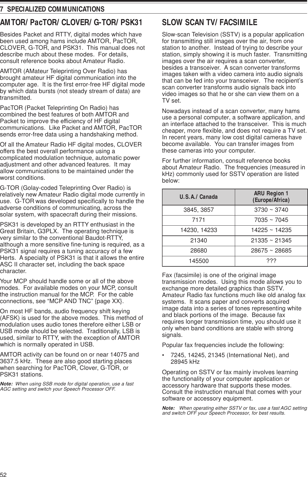
![53 7 SPECIALIZED COMMUNICATIONSDX PACKETCLUSTER TUNEDX PacketCluster is a packet network which consistof nodes and stations who are interested in DXingand contesting. If one station finds a DX station onthe air, he or she sends a notice to his or her node.This node then passes the information to all its localstations as well as another node. This transceivercan display received DX information and hold thelatest information on up to 10 DX stations.This transceiver is also capable of automaticallytuning in a reported DX station. In order to use theAuto Tune function, access Menu No. 49A and selectAUTO; the default is MANUAL.1Press [A/B] to select VFO A or VFO B.2Press [SUB] to activate the sub-band receiver.3The SUB band LED lights orange.4Tune to the frequency of the target DXPacketCluster node on the sub-receiver.5Press [FUNC], [SET/ P.C.T.] to enter thePacktClusters Monitor mode.• Each time new DX PacketCluster data isreceived, an alarm sounds and the informationis displayed on the sub-band as shown below:<DISPLAY>• Press [FUNC], [SET/ P.C.T.] again to exit thismode.6If you are using the Auto Tune function, press[SET/ P.C.T.].• The main band is tuned to the frequency of thereported DX station, on the sub-band.• Transmitting on the tuned frequencydeactivates the Auto Tune. Press [SET/ P.C.T.]again to reactivate it, if necessary.To access desired DX information from memory,press QUICK MEMO [MR], then turn the MULTI/ CHcontrol. Press [SET/ P.C.T.] to tune the main band tothe selected station. Press QUICK MEMO [MR]again to quit the DX information display.The transceiver can be set to output a Morse codeinstead of a beep when new DX PacketCluster data isreceived. Access Menu No. 49B and select MORSE.VOICE or OFF can also be set.Note:◆You cannot send DX information to a node using this function.◆The DX information in memory is cleared when the transceiverpower is turned OFF.NodeNodeNodeStationSATELLITE OPERATIONIt was in December of 1961 when the first Amateursatellite named OSCAR I was launched. OSCARstands for Orbiting Satellite Carrying Amateur Radio.Since then quite a few of Amateur satellites havebeen launched, and about 20 satellites are currentlyin orbit serving thousands of hams throughout theworld.Some Amateur satellites contain transponders thatreceive analog signals in one band, amplify them,shift their frequencies to another band, and retransmitthem. You can enjoy communications in SSB or CWwith other stations via these analog satellites. Mostof them are orbiting at relatively low altitudes and arecalled LEOs (Low Earth Orbit).Amateur satellites receive (uplink) on one band andtransmit (downlink) on another. Differentcombinations of uplink and downlink bands arerepresented by modes such as A, B, and K. Forexample, a Mode K satellite receives on the 21 MHzband and transmits on the 29 MHz band. Thistransceiver can handle the modes listed in the table.In order to work the satellites, you need a rotator thatallows azimuth and elevation control, plus a high-gaindirectional antenna. Your antenna has to tracksatellites which travel from horizon to horizon.However, many hams have been successfully usingfixed omnidirectional antennas. If you are using adirectional antenna, it would be wise to obtain a passprediction program.Doppler Shift is another aspect that you must takeinto account when working the satellites. As a targetsatellite travels away, frequencies on which you willreceive change. This transceiver has a function thatautomatically keeps the sum or difference betweenthe two frequencies identical when you change thereceive frequency.For further information, consult Internet Web pagesrelating to Amateur satellites. On Internet searchengines, use “AMSAT” as key words to find thoseWeb pages. AMSAT (Radio Amateur SatelliteCorporation) is the world wide organization ofAmateur Satellite operators and supporters. FromAMSAT Web pages, you can also download a varietyof utilities, including pass prediction programs, whichwill ease your satellite operations.edoM dnaBknilpU dnaBknilnwoDAzHM441zHM92BzHM)044(034zHM441AJzHM441zHM)044(034KzHM12zHM92TzHM12zHM441](https://usermanual.wiki/JVC-KENWOOD/31201110/User-Guide-119445-Page-61.png)
![547 SPECIALIZED COMMUNICATIONS1Press [SATL] to select Satellite mode.• The default downlink (435.9 MHz) and uplink(145.9 MHz) frequencies appear.• “TRACE”, “R”, and “SATL” appear to indicatethe current selections.<DISPLAY>2On VFO A, tune to the downlink frequency of thesatellite.3Press [LSB/ USB/ AUTO] or [CW/ FSK/ REV] toselect LSB, USB, or CW mode.4Press [A/B] to select VFO B.5Tune to the uplink frequency of the satellite.6Press [LSB/ USB/ AUTO] or [CW/ FSK/ REV] toselect LSB, USB, or CW mode.7If you are using a directional antenna, adjust itsazimuth and elevation.• If you have a pass prediction program, you canuse it to identify the exact location of thesatellite.• If you are using a fixed omnidirectionalantenna, skip this step.8With time, fine tune to the changing downlinkfrequency of the satellite using the Tuning control.• As you adjust the downlink frequency, theTrace function automatically changes the uplinkfrequency so that the sum of the twofrequencies is kept the same.• If necessary, press [A=B] to quit the Tracefunction. “TRACE” disappears.• The trace function can also change the uplinkfrequency so that the difference between thetwo frequencies is kept the same. Press[SPLIT]. “R” disappears.You can also store all the above selections in up to 10memory channels. Press [M.IN], then turn theMULTI/ CH control to select a channel from 0 to 9.Press [M.IN] again to store the selection in thechannel. To recall the desired channel after storing,rotate the MULTI/ CH control while in Satellite mode.In order to use the MULTI/ CH control to change thefrequency when in Satellite mode, press [VFO/ M].The MULTI/ CH LED turns off.](https://usermanual.wiki/JVC-KENWOOD/31201110/User-Guide-119445-Page-62.png)
![554To return the display to the current operatingmode, press [DISP/ SEL].Note:◆The cut-off frequencies can be adjusted independently foreach operating mode. When you change the operatingmode, the previous setting is recalled for each operatingmode.◆When the Packet filter (Menu No. 50A) is ON, you cannotchange the DSP filter bandwidth. Switch the Packet filterOFF to adjust the DSP filter bandwidth.■CW/ FSK Modes1Press [CW/ FSK/ REV] to select CW or FSKmode.2Press [DISP/ SEL].• The current filter selection appears.3Turn the LO/ WIDTH control clockwise toincrease (wide) the bandwidth, orcounterclockwise to decrease (narrow) thebandwidth.4As for CW, you can further adjust the shiftfrequency for passband. Turn the HI/ SHIFTcontrol to adjust the shift frequency from 400 to1000 Hz in steps of 50 Hz. The default shiftfrequency is 800 Hz.5To return the display to the current operatingmode, press [DISP/ SEL]. REJECTING INTERFERENCEDSP FILTERSKENWOOD digital signal processing (DSP)technology is used for the functions described in thissection. Using DSP filtering, the TS-2000 frees youfrom installing many analog filters for each operatingmode. Additionally, you can control the bandwidth,cancel the multiple jamming beat, and reduce thenoise level using DSP filtering technology.CHANGING THE RECEIVE BANDWIDTHFor improving interference reduction capability, thistransceiver also provides IF filters designed usingDSP technology. When in SSB, FM, or AM mode,you can change the filter bandwidth by altering its lowand/or high cut-off frequency. For CW and FSKmodes, you can change the filter bandwidth bydirectly specifying a bandwidth. Changing the filterbandwidth does not affect the current receivefrequency.Note:◆The receive filter bandwidth can be changed only on the maintransceiver.◆AF DSP filter is used for FM mode.■SSB/ FM/ AM Modes1Select SSB, FM, or AM mode.2Press [DISP/ SEL].• The current filter selection appears.3Turn the LO/ WIDTH control clockwise to raisethe low cut-off frequency, or counterclockwiseto lower the low cut-off frequency.Turn the HI/ SHIFT control clockwise to raisethe high cut-off frequency, or counterclockwiseto lower the high cut-off frequency.Interferingsignal Desiredsignal Interfering signaltsujdA )zH(snoitceleSycneuqerFHTDIW/OL ,004,003,002,001,05,0 ,009,008,007,006,005 0001TFIHS/IH ,0002,0081,0061,0041 ,0082,0062,0042,0022 0005,0004,0043,0003edoM )zH(snoitceleShtdiwdnaB tluafeD )zH(WC ,004,003,002,051,001,08,05 0002,0001,006,005 006KSF0051,0001,005,0520051edoM tuc-woltluafeD )zH(yceuqerf tuc-hgihtluafeD )zH(ycneuqerfMF/BSS0030062MA0010005LO/WIDTHffHI/SHIFTff](https://usermanual.wiki/JVC-KENWOOD/31201110/User-Guide-119445-Page-63.png)
![56Press [FUNC], [B.C./ MANUAL], then turn theMANUAL BC control to select the single BeatCancel frequency manually. You can select thebeat cancel frequency from approx. 230 Hz to3300 Hz by turning the control. Turn the controlclockwise to select a higher frequency andcounterclockwise to select a lower frequency.•Since the DSP Automatic Beat Cancel processesthe incoming signals at the AF stage, strong beatsignals may affect the AGC level. In this case,use the Auto Notch Filter instead, to remove thebeat signal from the IF passband filter.Note: While receiving intermittent CW signals, the transceiverclicks. This is not a malfunction.NOISE REDUCTION(N.R.1: ALL MODES, N.R.2: SSB/ CW/ FSK/ AM)This transceiver provides two types of NoiseReduction functions (1 and 2) for reducing randomnoise which interferes with the desired signal. Tryingthem both is the easiest way to judge which functionworks more effectively under the current conditions.Normally, select Noise Reduction 1 (Line Enchanced)in SSB mode and Noise Reduction 2 (SPAC) in CWmode.Press [N.R./ LEVEL] to toggle between NoiseReduction 1, Noise Reduction 2, and OFF.• “N. R. 1” or “N.R. 2” appears, depending on whichfunction is selected.■Setting the N.R. 1 Level AdjustmentThe Noise Reduction 1 (Line Enchanced Method)uses an adaptive filter to reduce the noise elementfrom the received signals. When the S/N ratio isreasonably goo in SSB, using N.R.1 will improvethe S/N further.While the N.R. 1 is ON, you can further adjust thenoise reduction level by pressing [FUNC],[N.R./ LEVEL], then turn MULTI/ CH control toselect the level from 1 to 10 or AUTO. The defaultis AUTO.■Setting the N.R. 2 Time ConstantYou can change the correlation time for NoiseReduction 2 (SPAC). When in SSB mode, selectthe correlation time that allows you to hear signalswith more clarity. When receiving CW, it is best toselect the longest correlation time that allowsreliable reception. The longer the correlation time,the better the S/N ratio.When Noise Reduction 2 is ON, press [FUNC],[N.R./ LEVEL], then turn the MULTI/ CH control toselect the correlation time from 2 ms to 20 ms.The default is 20 ms.Note:◆Using Noise Reduction 2 in SSB mode may lower the clarityof signals or induce pulse noise, depending on theconditions.◆Only N.R. 1 is available for the sub-receiver. However, thelevel cannot be adjusted. 9 REJECTING INTERFERENCENOTCH FILTER (SSB)Auto Notch filter automatically locates and attenuatesany single interfering tone within the receive passband. This function operates digitally at the IF filterlevel, hence it can affect your S-meter reading andmay also affect (slightly attenuate) your desiredsignal. However, controlling the AGC level bynotching out the strong interfering beat signals couldbring up the desired SSB signal that is covered by theinterfering beat signal. If the interfering tone is weak,you may find that Beat Cancel eliminates them moreeffectively.Press [A.N./ LEVEL] to toggle the Auto Notch FilterON and OFF.•“A.N.” appears when the function is ON.•The interfering beat signals are notched out.If the interfering beat signals change the tonefrequency randomly, you can adjust the Auto Notchlevel.Press [FUNC], [A.N./ LEVEL] to access the AutoNotch level adjustment, then turn the MULTI/ CHcontrol to select the level from 0 to 5. Level 1 is theslowest beat tone tracking speed and Level 5 is thefastest. Level 0 terminates the beat tone tracking.BEAT CANCEL (SSB/ AM)Beat Cancel uses an adaptive filter and attenuatesmore than one cyclic interference within the receivepass band. The adaptive filter changes itscharacteristics according to the nature of the signalbeing received at any given moment. You can useautomatic Beat Cancel when in SSB or AM mode.Press [B.C./ MANUAL] to toggle the Auto BeatCancel ON and OFF.•“B. C.” appears when the function is ON.•If desired, you can manually control the beatcancel frequency.BeforeInterferingtonesAfterReceive pass bandDesiredsignalBeforeInterferingtonesAfterReceive pass bandDesiredsignal](https://usermanual.wiki/JVC-KENWOOD/31201110/User-Guide-119445-Page-64.png)
![57ATTENUATORThe Attenuator reduces the level of received signals.This function is useful when there is stronginterference from adjacent frequencies.Press [ATT/ F LOCK] to toggle the Attenuator ONand OFF.• “ATT” appears when the function is ON.The ON/OFF setting will be automatically stored inthe current band. Each time you select the samefrequency band, the attenuator setting will beautomatically recalled.The frequency range of each band is available below.Note: If the same frequency (144 MHz or 430 (440) MHz) band isselected on both the main transceiver and the sub-receiver, theattenuator can be switched ON or OFF for both receivers. This isbecause the main transceiver and sub-receiver share the sameantenna. 9 REJECTING INTERFERENCENOISE BLANKERNoise Blanker was designed to reduce pulse noisesuch as that generated by automobile ignitions.Noise Blanker does not function in FM mode.Press [NB/ LEVEL] to toggle the Noise Blanker ONand OFF.• “NB” appears when the function is ON.You can further adjust the Noise blanker level from 1to 10. The default level is 6.Press [FUNC], [NB/ LEVEL], then turn theMULTI/ CH control to adjust the noise blanker level.• “NB LEVEL” and the current level appear on thesub dot-matrix display.Note: Noise Blanker is available only for the main transceiver inSSB, CW, FSK, and AM modes.PRE-AMPLIFIERSwitching the Pre-amplifier OFF may help reduceinterference from adjacent frequencies.Press [PRE/ LOCK A] to toggle the Pre-amplifier ONand OFF.• “PRE” appears when the function is ON.The ON/OFF setting will be automatically stored inthe current band. Each time you select the sameband, the same setting will be automatically selected.The frequency range of each band is provided in thefollowing table (under “ATTENUATOR”).Note: If the same frequency (144 MHz or 430 (440) MHz) bandis selected on both the main transceiver and the sub-receiver, thepre-amplifier can be switched ON or OFF for both receivers. Thisis because the main transceiver and sub-receiver share the sameantenna.sdnaBycneuqerF )zHM( reifilpma-erP )tluafeD( rotaunettA )tluafeD(5.2~30.0FFOFFO1.4~5.2FFOFFO5.7~1.4FFOFFO5.01~5.7NOFFO5.41~5.01NOFFO5.81~5.41NOFFO5.12~5.81NOFFO5.52~5.12NOFFO0.03~5.52NOFFO0.06~0.03NOFFO003~811NOFFO215~003NOFFO0031~0421NOsyawlA syawlA FFO](https://usermanual.wiki/JVC-KENWOOD/31201110/User-Guide-119445-Page-65.png)
![58MEMORY CHANNELSThe TS-2000 provides you with 300 memorychannels, numbered 00 to 299, for storing operatingfrequency data, modes and other information.Memory channels 00 to 289 are called ConventionalMemory Channels. Memory channels 290 to 299 aredesigned for programming VFO tuning ranges andscan ranges. The data you can store is listed below:Conventional memory is used for storing data you willoften recall. For example, you may store thefrequency where you regularly meet your clubmembers.1 Changing the data after recalling a memory channel overwrites the contents of the channel.retemaraP lennahC 982~00 lennahC 992~092ycneuqerfXRseY seY1)xelpmis(ycneuqerfXTseYedomXRseY seY1)xelpmis(edomXTseYseicneuqerfdnE/tratSoNseYycneuqerftesffOseYseYnoitceridtfihSseYseYedomesreveRseYseYezispetsycneuqerfXRseY seY )xelpmis(ezispetsycneuqerfXTseYycneuqerfenoTseYseYycneuqerfSSCTCseYseYedocSCDseYseYedomSCD/SSCTC/enoT FFO/NO seYseYemanyromeMseYseYtuokcoLlennahCyromeM FFO/NO seY1seY1 MEMORY FEATURESSTORING DATA IN MEMORYThere are 2 methods used for storing transmit/receivefrequencies and associated data in memory channels00 to 289. Use either method, depending on therelationship of the receive and transmit frequenciesyou store:• Simplex channels:RX frequency = TX frequency• Split-frequency channels:RX frequency ≠ TX frequencyMemory channels 290 to 299 can also be used assimplex channels.Note: When RIT or XIT is ON, the frequency that includes the RITor XIT offset will be stored.■Simplex Channels1Press [A/B] to select VFO A or VFO B.•“t A” or “t B” appears to show which VFOis selected.2Select the frequency, mode, etc. to be stored.3Press [M.IN] to enter Memory Scroll mode.• To exit Memory Scroll mode and abort thestorage process, press [CLR].4Turn the MULTI/ CH control, or press Mic [UP]or [DWN] to select a memory channel.• You can also select a channel by entering a3-digit number, such as 012, using thenumeric keys.5Press [M.IN] again to store the data.• The previous data stored in the channel isoverwritten.](https://usermanual.wiki/JVC-KENWOOD/31201110/User-Guide-119445-Page-66.png)
![5910 MEMORY FEATURESMEMORY RECALL AND SCROLLThere are two modes which allow you to retrievefrequencies and associated data that you stored in amemory channel: Memory Recall and Memory Scroll.Memory Recall:In this mode, the transceiver receives and transmitsusing a frequency that you retrieve. You cantemporarily change the frequency and associateddata without overwriting the contents of the memorychannel when Menu No. 06B is set to ON.Memory Scroll:Use this mode to check the contents of the memorychannels without changing the current receivefrequency. In this mode, frequencies you retrieve arenot used for receiving and transmitting.■Memory Recall1Press [VFO/M] to enter Memory Recall mode.• The memory channel that was last selectedappears.2Turn the MULTI/ CH control, or press Mic [UP]or [DWN] to select a memory channel.• Continuously holding down Mic [UP] or[DWN] steps the transceiver through thememory channels until the key is released.• Memory channels which contain no data areskipped.• You cannot change memory channels whiletransmitting.3To exit Memory Recall mode, press [VFO/M].Note: Memory channels can also be changed while using theTF-SET function.■Split-Frequency Channels1Press [A/B] to select VFO A or VFO B.•“tA” or “tB” appears to show which VFOis selected.2Select the frequency, mode, etc. to be stored.• This frequency and mode will be used fortransmitting.3Press [A/B] to select the other VFO.4Select the receive frequency and mode.5Press [SPLIT].• “SPLIT” appears.6Press [M.IN] to enter Memory Scroll mode.• To exit Memory Scroll mode and abort thestorage process, press [CLR].7Turn the MULTI/ CH control, or press Mic [UP]or [DWN] to select a memory channel.• You can also select a channel by entering a3-digit number, such as 012, using thenumeric keys.8Press [M.IN] again to store the data.•The previous data stored in the channel isoverwritten.Note: When subtone frequencies differ between TX and RXwhile performing memory-VFO split operation, the subtonefrequency for TX will be stored in the memory channel.](https://usermanual.wiki/JVC-KENWOOD/31201110/User-Guide-119445-Page-67.png)
![6010 MEMORY FEATURESMEMORY-VFO SPLIT OPERATIONUnder “SPECIALIZED COMMUNICATING”{page XX}, you learned about split-frequencyoperation using two VFOs. Recalling a split-frequency channel is another way to perform split-frequency operation. If you access Menu No. 07and select ON, you can also use a memorychannel and a VFO together for this operation, asfollows:• RX: Memory channelTX: VFO A or VFO B• RX: VFO A or VFO BTX: Memory channelTo use a memory channel for receiving:1Access Menu No. 06A and select ON.2Press [A/B] to select the VFO that you will usefor transmitting.•“tA” or “tB” appears to show which VFOis selected.3Select the frequency for transmitting.4Recall a memory channel by pressing[VFO/M].5Turn the MULTI/ CH control to select a memorychannel to receive.6Press [SPLIT].7The VFO A frequency appears on the subdisplay. If you want to use the VFO Bfrequency to transmit, press [SPLIT] again.8Press [SEND] or Mic [PTT] to transmit on thefrequency shown on the sub display.9Press [SPLIT] to exit the SPLIT operation.• If Split operation is still selected using VFOA or VFO B, press [SPLIT] again to exitSplit operation.To use a memory channel for transmitting:1Access Menu No. 06A and select ON.2Recall a memory channel by pressing[VFO/M].3Turn the MULTI/ CH control to select a memorychannel to transmit.4Press [VFO/M] to return to VFO mode .5Press [SPLIT]. The other VFO frequencyappears on the sub display for transmission(Normal SPLIT operation).6Press [SPLIT] again. The memory channelyou selected in step 3 appears on the subdisplay for transmission.7Press [SEND] or Mic [PTT] to transmit on thefrequency in the memory channel.8Press [SPLIT] to exit SPLIT operation.■Memory Scroll1Press [M.IN] to enter Memory Scroll mode.•The memory channel that was last selectedappears.<TS-2000/Diagram 60-01>2Turn the MULTI/ CH control, or press Mic [UP]or [DWN] to step through the memorychannels.• You can also change channels by entering a3-digit number, such as 012, using thenumeric keys, then pressing [ENT].3To exit Memory Scroll mode, press [CLR].• The transceiver re-displays the memorychannel or VFO frequency that wasselected before you activated MemoryScroll.Note: Do not press [M.IN] again after entering Memory Scrollmode. Pressing [M.IN] results in over-writing the current VFOdata to the memory channel you selected.■Temporary Frequency ChangesAfter retrieving frequencies and associated data inMemory Recall mode, you can temporarily changethe data without overwriting the contents of thememory channel.1Access Menu No. 06B and select ON.• Skip this step when changing only theassociated data (not the frequency).2Recall a memory channel.3Change the frequencies and associated data.• Use only the Tuning control to select afrequency.4If necessary for future use, store the changeddata in another memory channel. Refer to“Channel ➡ Channel Transfer” {page 61}.Note: Memory channel data can also be changed while usingthe TF-SET function.](https://usermanual.wiki/JVC-KENWOOD/31201110/User-Guide-119445-Page-68.png)
![6110 MEMORY FEATURESMEMORY TRANSFER■Memory ➡ VFO TransferAfter retrieving frequencies and associated datafrom Memory Recall mode, you can copy the datato the VFO. This function is useful, for example,when the frequency you want to monitor is nearthe frequency stored in a memory channel.1Recall the desired memory channel.2Press [MsssssVFO/ MG.SEL].• When a simplex channel is recalled, thedata is copied to VFO A or VFO B,depending on which VFO was used to recallthe channel.• When a split channel is recalled, the RXdata is copied to VFO A and the TX data iscopied to VFO B.Note:◆The Memory Channel Lockout status and the subtonefrequency are not copied.◆Pressing [MsssssVFO/ MG.SEL] after temporarily changingthe retrieved data copies the new data to the VFO.■Channel ➡ Channel TransferYou can also copy channel information from onememory channel to another. This function isuseful when storing frequencies and associateddata that you temporarily change in MemoryRecall mode.1Recall the desired memory channel.2Press [M.IN] to enter Memory Scroll mode.• To exit Memory Scroll mode, press [CLR].3Select the memory channel where you wouldlike the data copied, using the MULTI/ CHcontrol.4Press [M.IN] again.982~00lennahC a982~00lennahCycneuqerfXR aycneuqerfXRycneuqerfXT aycneuqerfXTXRrofedoM aXRrofedoMXTrofedoM aXTrofedoMycneuqerftesffO aycneuqerftesffOnoitceridtfihS anoitceridtfihSFFO/NOesreveR aFFO/NOesreveRpetsycneuqerfXR apetsycneuqerfXRpetsycneuqerfXT apetsycneuqerfXTycneuqerfenoT aycneuqerfenoTycneuqerfSSCTC aycneuqerfSSCTCedocSCD aedocSCDSCD/SSCTC/enoT FFO/NO aSCD/SSCTC/enoT FFO/NOemaNyromeM aemaNyromeMlennahCyromeM FFO/NOtuokcoL alennahCyromeM FFOtuokcoL982~00lennahC a992~092lennahCycneuqerfXR aycneuqerfXR/XT )xelpmis(ycneuqerfXT aXRrofedoM aXR/XTrofedoM )xelpmis(XTrofedoM aycneuqerftesffO aycneuqerftesffOnoitceridtfihS anoitceridtfihSFFO/NOesreveR aFFO/NOesreveRpetsycneuqerfXR aycneuqerfXR/XT )xelpmis(petspetsycneuqerfXT aycneuqerfenoT aycneuqerfenoTycneuqerfSSCTC aycneuqerfSSCTCedocSCD aedocSCDSCD/SSCTC/enoT FFO/NO aSCD/SSCTC/enoT FFO/NOemaNyromeM aemaNyromeMlennahCyromeM FFO/NOtuokcoL alennahCyromeM FFOtuokcoL992~092lennahC a982~00lennahCycneuqerfXR/XT aycneuqerfXRaycneuqerfXTXR/XTrofedoM aXRrofedoMaXTrofedoMycneuqerftesffO aycneuqerftesffOnoitceridtfihS anoitceridtfihSFFO/NOesreveR aFFO/NOesreveRycneuqerfXR/XT )xelpmis(petsapetsycneuqerfXRapetsycneuqerfXTycneuqerfenoT aycneuqerfenoTycneuqerfSSCTC aycneuqerfSSCTCedocSCD aedocSCDSCD/SSCTC/enoT FFO/NO aSCD/SSCTC/enoT FFO/NOemaNyromeM aemaNyromeMlennahCyromeM FFO/NOtuokcoL alennahCyromeM FFOtuokcoLThe tables above illustrate how data is transferredbetween memory channels:](https://usermanual.wiki/JVC-KENWOOD/31201110/User-Guide-119445-Page-69.png)
![6210 MEMORY FEATURESSTORING FREQUENCY RANGESMemory channels 290 to 299 allow you to storefrequency ranges for VFO tuning and Program Scan.Program Scan is described in the next chapter. Totune or scan frequencies within a specified range,store the start and end frequencies for that range inadvance.1Press [A/B] to select VFO A or VFO B.2Select the desired start frequency.3Press [M.IN] to enter Memory Scroll mode.• To exit Memory Scroll mode and abort thestorage process, press [CLR].4Turn the MULTI/ CH control, or press Mic [UP] or[DWN] to select a memory channel in the range of290 to 299.• You can also select a channel by entering a3-digit number, such as 290, using the numerickeys.5Press [M.IN] to store the start frequency in thememory channel.• “CLOSE INPUT” appears on the sub dot-matrixdisplay.6Turn the MAIN control or the MULTI/ CH control toselect the end frequency.7Press [M.IN] to store the end frequency in thememory channel.• The previous data stored in the channel isoverwritten.■Confirming Start/End FrequenciesUse this procedure to check the start and endfrequencies that you stored in channels 290 to299.1Press [VFO/M] to enter Memory Recall mode.2Turn the MULTI/ CH control, or press Mic [UP]or [DWN] to select a memory channel from 290to 299.3Press [–] to check the start frequency and [+]to check the end frequency.■Programmable VFOUsing the start and end frequencies that youstored in channels 290 to 299, ProgrammableVFO restricts the frequency range that you cantune with the Tuning control. One application ofthis function is to help you operate within theauthorized frequency limits of your license.1Press [VFO/M] to enter Memory Recall mode.2Turn the MULTI/ CH control, or press Mic [UP]or [DWN] to select a memory channel from 290to 299.Now you can only tune from the start frequency tothe end frequency, using the MAIN control.Note: Pressing [UP]/ [DWN] or turning the MULTI/ CH controlresults changing the memory channel number while in ProgramableVFO mode.MEMORY CHANNEL LOCKOUTYou can lock out memory channels that you prefernot to monitor during Memory Scan. MemoryScan is described in the next chapter {page 68}.1Press [VFO/M] to enter Memory Recall mode.2Turn the MULTI/ CH control, or press Mic [UP]or [DWN] to select the memory channel.3Press [CLR] momentarily.• Pressing [CLR] for more than approximately2 seconds erases the contents of thememory channel.• A dot appears beside the right-most digit ofthe memory channel number to indicate thechannel has been locked out.• Repeatedly pressing [CLR] togglesbetween adding and removing the channelfrom the scan list.ERASING MEMORY CHANNELSIf there are memory channels that you will not recallin the future, you may prefer erasing the contents ofthose channels.1Press [VFO/M] to enter Memory Recall mode.2Turn the MULTI/ CH control, or press Mic [UP] or[DWN] to select the memory channel.• You can also select a channel by entering a3-digit number, such as 012, using the numerickeys.3Press and hold [CLR] for approximately twoseconds.•A long beep sounds to confirm that the channeldata is erased.](https://usermanual.wiki/JVC-KENWOOD/31201110/User-Guide-119445-Page-70.png)
![6310 MEMORY FEATURESMEMORY CHANNEL NAMEYou can assign a name to each memory channel. Amaximum of 7 alpha-numeric characters can bestored.1Press [M.IN] to enter Memory Scroll mode.2Turn the MULTI/ CH control, or press Mic [UP] or[DWN] to select a memory channel.3Press [DISP].<DISPLAY>4Press [+] or [–] to select a desired alpha-numericcharacter. You can move the cursor to the left bypressing [MAIN], or to the right by pressing[SUB]. Or, you can use an optional DTMFmicrophone to enter alpha-numeric characters.Note: Alpha-numeric entries are limited to those charactersshown in the following DTMF character table.5After selecting all the necessary characters for thememory channel name, press [M.IN] to store thename, or press [DISP] to select a Memory Group.You can select only one of 10 groups (0 to 9).Enter the desired group number by pressing anumeric key. The selected group is shown in alarger font. After selecting a group, press [M.IN]to store the name and group number in thememory channel.6When you recall a memory channel with a name,the name is displayed on the dot-matrix displayalong with the memory channel number andgroup number {page 64}.Available characters using the [+]/[–] keysFMTD yek sretcarahcelbaliavA1qz1QZ2abc2ABC3def3DEF4ghi4GHI5jkl5JKL6mno6MNO7p r s 7PRS8tuv8TUV9wxy9WXY0ecaps0#?! ' .,–/&# ( )<> ;:"@*noitcnufoNAthgirrosrucehtevoMBtfelrosrucehtevoMCretcarahcdetcelesehteteleDDsaemaS ]NI.M[ yekAvailable characters using a DTMF MicsretcarahcelbaliavAABCDEFGH I JKLMNOPQRSTUVWXY Z [ ¥ ] ^_`abcdefghi j k lmnopqrstuvwxyz{ |}~\ PS!"#$%&’()*+,–./0123456789:;<=>?@sepyt-EllarofsretcarahclanoitiddAÀÁÂÃÄÅÆŒÇÈÉÊËÌÍÎÏ ÑÒÓÔÕÖØÙÚÛÜŸàáâãäæœçèéêëìíîïñòóôõöøùúûü ÿßå](https://usermanual.wiki/JVC-KENWOOD/31201110/User-Guide-119445-Page-71.png)
![6410 MEMORY FEATURESQUICK MEMORYQuick memory is designed to quickly and temporarilysave data without specifying a particular memorychannel. Use Quick memory to store data you willnot use in future operating sessions. For example, asyou tune across the band looking for DX, it isconvenient to store stations that you want to contact.You can quickly jump between several differentmemory channels as you monitor them.This transceiver provides ten Quick memory channels(“0_” to “9_”) that can store the following data:STORING INTO QUICK MEMORYEach time you store a new frequency, all previouslystored frequencies are bumped to the next respectiveQuick memory channel. When all ten memorychannels contain frequencies, storing one morefrequency bumps the contents of memory channel 9off the stack (the data is lost).The following diagram illustrates how the QuickMemory stacks the data in memory each time youpress QUICK MEMORY [M.IN].dnaycneuqerfAOFV edomgnitarepo dnaycneuqerfBOFV edomgnitarepoFFO/NOreviecer-buS ycneuqerfreviecer-buS edomgnitarepodnaFFO/NOTIRFFO/NOTIXycneuqerftesffoTIX/TIRhtdiwdnabretlifrevieceRFFO/NOreknalBesioNFFO/NOENIFnoitcudeResioNPSD 2/1/FFO lecnaCtaeBPSD FFO/NOhctoNotuAPSD FFO/NO snoitcnufXR/XT24.911Memory 0144.005Memory 114.235Memory 2441.250Memory 318.111Memory 450.015Memory 57.082Memory 629.610Memory 73.545Memory 8145.250Memory 921.005Memory 024.911Memory 1144.005Memory 214.235Memory 3441.250Memory 418.111Memory 550.015Memory 67.082Memory 729.610Memory 83.545Memory 914.085Memory 021.005Memory 124.911Memory 2144.005Memory 314.235Memory 4441.250Memory 518.111Memory 650.015Memory 77.082Memory 829.610Memory 9MEMORY GROUPTo manage 300 memory channels, you can dividethem up into a maximum of 10 groups (Groups 0 to9). After you configure a Memory Group, you canselect only one or more of the Memory Groups youwant to recall, in Memory Recall mode. As a default,all memory channels are stored in Group 0.To change the Memory Channel Group:1Press [M.IN] to enter Memory Scroll mode.2Select the desired memory channel for which youwant to change the Memory Group by turning theMULTI/ CH control.3Press [DISP].• The Memory Name input prompt appears.Press [DISP] again to skip the input or enter aMemory Name using [+]/ [–] and [MAIN]/[SUB] {page 63}.4The current Memory Group appears in a largerfont.<TS-2000/ Diagram 64-03>5Press a numeric key to change the selectedGroup number. The newly selected Groupnumber appears in a larger font.6Press [M.IN] to store the settings.■Memory Group SelectAfter you configure Memory Groups to the MemoryChannels, you can select one or more of the Groupsto be recalled in Memory Recall mode.To select Memory Groups:1Press [FUNC], [MsssssVFO/ MG.SEL] to enterMemory Group Select mode.2Number 0 ~ 9 appears in the main dot-matrixdisplay. The selected Memory Group numbers aredisplayed in larger fonts. To change the selection,press a numeric key. To select all the MemoryGroups, press [•/ DCS/SEL]. At least, oneMemory Group must be selected.<TS-2000/ Diagram 64-04>3Press [M.IN] to save the setting and exit.4You can now recall only the selected MemoryGroups in Memory Recall mode.](https://usermanual.wiki/JVC-KENWOOD/31201110/User-Guide-119445-Page-72.png)
![6510 MEMORY FEATURESYou can store data in the Quick Memory only whenusing VFO frequencies for both transmitting andreceiving.1Select the frequency, mode, etc. on the maintransceiver or sub-receiver VFO.2Press QUICK MEMO [M.IN].• Each time QUICK MEMO [M.IN] is pressed,the current VFO data is written to Quickmemory.Note: When RIT or XIT is ON, this ON status and the offset willalso be stored.RECALLING QUICK MEMORY CHANNELSYou can recall a Quick memory channel only whenusing VFO frequencies for both transmitting andreceiving.1Press QUICK MEMO [MR].• The current memory channel number appears.• If there is no data stored in any Quick memorychannel or no data cannot be recalled to thecurrent VFO, an error beep sounds.2Turn the MULTI/ CH control to select a Quickmemory channel (0 to 9).• You cannot change memory channels whiletransmitting.3To exit, press QUICK MEMO [MR] again.Note: Memory channels cannot be changed while using theTF-SET function.TEMPORARY FREQUENCY CHANGESAfter recalling a Quick memory channel, you cantemporarily change the data without overwriting thecontents of the channel. You can change thefrequency even when you select OFF in MenuNo. 06B.1Press QUICK MEMO [MR].2Turn the MULTI/ CH control to select a Quickmemory channel (0 to 9).3Change the frequencies and associated data.4To store the changed data in Quick memory, pressQUICK MEMO [M.IN].•This action stores the new data in the currentchannel and bumps the old frequency to thenext higher Quick memory channel.5To exit, press QUICK MEMO [MR] again.Note: Memory channel data can also be changed while using theTF-SET function.QUICK MEMORY ➡ VFO TRANSFERThis function copies the contents of the recalledmemory channel to the VFO.1Recall a Quick memory channel.2Press [MsssssVFO/ MG.SEL].Note: Pressing [MsssssVFO/ MG.SEL] after temporarily changingthe recalled data copies the new data to the VFO.](https://usermanual.wiki/JVC-KENWOOD/31201110/User-Guide-119445-Page-73.png)
![66 SCANScan is a useful function for hands-off monitoring ofyour favorite frequencies. By becoming comfortablewith all types of Scan, you will increase youroperating efficiency.This transceiver provides the following types ofscans.* Visual Scan graphically shows how frequencies in a specificrange are busy.Note:◆While using CTCSS or DCS, Scan stops only for the signals thatcontain the same CTCSS tone or DCS code that you selected.◆When using S-meter Squelch, Scan stops when the receivedsignal strength matches or exceeds the S-meter setting. Scanresumes 2 seconds after the signal level drops below theS-meter setting.◆Pressing and holding Mic [PTT] causes Scan to temporarily stopif it is functioning on a non TX band. Pressing [PTT] on thescanning band causes Scan to stop.◆Starting Scan switches OFF the Automatic Simplex Checker.NORMAL SCANWhen you are operating the transceiver in VFOmode, 2 types of scanning are available.• VFO ScanThe transceiver scans the entire band of thefrequency you selected. For example, if you areoperating and receiving on the main transceiver’sVFO A at 14.195.00 MHz, it scans all thefrequencies in the range of 30.00 kHz to60.00000 MHz. (Refer to VFO frequency range inAppendix XX.)• Program ScanBy programming the start and end frequency inMemory channels 290 ~ 299 {page 62}, you canlimit the scanning frequency range. Since thereare 10 memory channels (290 - 299) available forspecifying the start and end frequency, you canselect one or more (a maximum of 10) ranges toscan. This is useful when you are waiting for a DXstation on a certain frequency but the station mayappear on slightly higher or lower frequency.VFO SCANVFO Scan scans the entire frequency range that isavailable for the current VFO. When the ProgramScan frequency range is not programmed or no ScanGroup is selected for the Program Scan, thetransceiver also scans the entire frequency rangeavailable for the current VFO.If one or more Program Scan frequency ranges areprogrammed in memory channels 290 to 299:1Press [FUNC], [SCAN/ SG.SEL].2If one or more memory channels are selected forthe Program Scan, the selected channels aredisplayed in a larger font on the main dot-matrixdisplay.In this case, press [•/ DCS/SEL] to temporarilydeselect all the channels.When there are no Scan Group channelsselected, “VFO SCN MODE” appears on the subdot-matrix display.3Press [SCAN/ SG.SEL] to return to the currentVFO mode.4Press [SCAN/ SG.SEL] to start the VFO Scan.Note:◆While scanning, you can change the scan speed by turning theRIT/ SUB control. Turn the control clockwise/ counterclockwiseto decrease/ increase the scan speed. The speed indicatorappears on the main dot-matrix display, where P1 is the fastestspeed and P9 is the slowest.◆You cannot change the VFO Scan speed in FM mode.◆You cannot change the VFO Scan speed on the sub-receiver.epyTnacS esopruPlamroN nacSnacSOFV ehtfodnaberitneehtsnacS detcelesuoyycneuqerfmargorP nacSycneuqerfcificepsehtsnacS yromeMniderotssegnar 992~092slennahcnacSzHM nihtiwseicneuqerfehtsnacS egnarzHM1ayromeM nacSlennahC-llA nacS ,slennahcyromeMllasnacS 992ot00morfpuorG nacS yromeMcificepsehtsnacS spuorglennahcllaC nacSOFV dnalennahcllaCehtsnacS ycneuqerfOFVtnerrucehtyromeM lennahC dnalennahcllaCehtsnacS lennahcyromeMdetcelesehtlausiV *nacSOFVgnitarepotnerrucehtsnacS asallewsaycneuqerf forebmundeificeps wolebdnaevobaseicneuqerf langisehT.ycneuqerftaht silennahchcaefohtgnerts hparg-rabanideyalpsidyromeM lennahCslennahcyromeMehtsnacS langisehtsyalpsiddna anilennahchcaefohtgnerts hparg-rab](https://usermanual.wiki/JVC-KENWOOD/31201110/User-Guide-119445-Page-74.png)
![11 SCAN6711 SCANPROGRAM SCANProgram Scan monitors the range between thestart and end frequencies that you have stored inConventional memory channels 290 to 299. Referto “STORING FREQUENCY RANGES” {page 62}for details on how to store the start and endfrequencies.You can select a maximum of 10 memorychannels (Memory channels 290 to 299) andsequentially scan the ranges that you stored inthese channels. Program Scan starts with thesmallest channel number and repeats thesequence as described below.1Press [A/B] to select VFO A or VFO B.• If you are operating the sub-receiver, press[VFO/ M] to select VFO mode.2Press [FUNC], [SCAN/ SG.SEL].3If no Program scan channel is selected, allmemory channel numbers (from 290 to 299)are displayed in small fonts. Only the one’sdigit of each memory channel is displayed onthe main dot-matrix display. 0 representschannel 290, 1 represents channel 291, 2represents channel 292, etc.4To select the Program scan frequency range,press a numeric key 0 to 9. For example,press [3] for channel 293 only or press [3], [5],[7] to select the channels 293, 295, and 297.When a channel is selected for the ProgramScan, the number is displayed in a larger font.To temporarily deselect all the channels (290 to299) so that you can perform the VFO Scan,press [•/ DCS/ SEL]. (Refer to “VFO SCAN”on page 66)Note :◆At least one of the valid Program Scan channels (from 290 to299) must be programmed and selected to perform theProgram Scan. If no Program channel is selected oravailable for the Program Scan, the transceiver performs theVFO Scan.◆When performing the Program Scan on the sub-receiver, thefrequencies must be within the sub-receiver frequency rangelimitations. Otherwise, the Program scan cannot beperformed. The same conditions apply to the maintransceiver.<DISPLAY>5Press [SCAN/ SG.SEL] to start the ProgramScan.• To quickly move towards a desired frequencywhile scanning, turn the Tuning control or theMULTI/ CH control, or press Mic [UP]/[DWN].• When in a mode other than FM mode, turningthe RIT/ SUB control clockwise decreases thescan speed, and counterclockwise increasesthe speed. The current scan speed is shownon the display; P1 is the fastest speed and P9is the slowest.• While in FM mode, Scan automatically stopson a frequency where a signal is present. Thetransceiver will either remain on that channelfor a short time (Time-operated mode) or untilthe signal drops out (Carrier-operated mode),depending on which mode you select via MenuNo. 10 {page 68}.6To stop Scan, press [SCAN/ SG.SEL] or [CLR].Note:◆If you are operating on the sub-receiver and perform theProgram Scan, the sub-receiver automatically skips thememory channels that cannot be scanned on the sub-receiver.The same conditions also apply to the main transceiver.◆If you have turned the MAIN SQL or SUB SQL controlclockwise, far beyond the squelch threshold when in FMmode, Scan may fail to stop at a channel where a signal ispresent. If this happens, turn the MAIN SQL or SUB SQLcontrol slightly counterclockwise.◆If you press [SCAN/ SG.SEL] before storing any frequencyrange for memory channels 290 to 299, the transceiver startsVFO scan.◆When the current receive frequency is within one of the rangesthat you selected with channel numbers, Scan starts with thecurrent frequency. The operating mode stored in the memorychannel is used.◆When the current receive frequency is outside all the rangesthat you selected with the channel numbers, Scan starts withthe start frequency stored in the smallest channel number.◆The operating mode can be changed while scanning, but thememory channel is overwritten with the changed mode.◆When the current Scan range is smaller than a single step ofthe MULTI/ CH control, turning the control clockwise causesScan to jump to the start frequency, and counterclockwise tothe end frequency.◆Starting Program Scan switches OFF the RIT and XITfunctions.◆While in FM mode, the Program Scan monitors rounded offfrequencies regardless of the Menu No. 04 setting.◆You cannot change the scan speed on the sub-receiver.PROGRAM SCAN PARTIALLY SLOWEDYou can specify a maximum of 5 frequency points foreach memory channel from 290 to 299 so that theProgram Scan slows down the scanning speed. Tospecify the slow down frequency points, first programthe start and end frequencies into a memory channel(290 ~ 299) {page 62}.1Access Menu No. 07 to set the function ON(default is OFF).2You can further configure the slow down frequencywidth. Access Menu No. 08 to select the rangefrom 100 Hz to 500 Hz.Note: If you select, for example, 500 Hz for Menu No. 08, theProgram Scan slows down to a ±500 Hz width, centering thefrequency you marked below.](https://usermanual.wiki/JVC-KENWOOD/31201110/User-Guide-119445-Page-75.png)
![11 SCAN683Press [VFO/ M] to recall the memory channel(290 - 299) for which you want to specify the scanslow down frequencies.4Press [+] or [–] to confirm the start or endfrequency.5Turn the Tuning control to the center frequencypoint that you want the Program Scan to slowdown. Press QUICK MEMO [M.IN] to mark theSlow down frequency point. The icon appears.6Repeat step 5 to specify the center slow downfrequency points. You can specify a maximum of5 frequency points for each channel.7If you want to clear the slow down frequeny pointsthat you previously stored, press and hold QUICKMEMO [M.IN] for 1 second. A confirmation beepsounds and the transceiver clears all the slowdown frequency points you specified in thememory channel.Note: You must clear all the previous slow down frequencypoints; you cannot clear only specific points.8Press [VFO/ M] to return to VFO mode.9Press [SCAN/ SG.SEL] to start the Program Scanwith the slow down frequency point(s).Note:◆During the Program Scan, you can turn the RIT/ SUB control toadjust the scanning speed. Turn the control clockwise/ counter-clockwise to slow down/ speed up the scan. The Program Scanspeed indicator appears on the main dot-matrix display duringthe Program Scan; P1 is the fastest speed and P9 is the slowest.◆You cannot change the Program Scan speed in FM mode.◆You cannot change the scan speed on the sub-receiver.◆You cannot specify the Program Scan slow down frequencypoint for FM mode.SCAN HOLDThis function stops Program Scan for approximately 5seconds, then resumes Scan when you jump to thedesired frequency by turning the Tuning control orthe MULTI/ CH control, or by pressing Mic [UP]/[DWN].To use this function, access Menu No. 09, and selectON. The default is OFF.MHz SCANWhen you operate the main transceiver or sub-receiver in VFO mode, you can scan an entire 1 MHzfrequency range within the current VFO frequency.1Press [VFO/ M] to select VFO mode.2Select the desired frequency to perform the MHzScan. If you want to scan the entire 145 MHzfrequency, for example, select 145.650 MHz.Scan will operate between 145.00000 MHz and145.99999 MHz.3Press and hold [1MHz/ SEL] to start the MHzScan.4Turn the RIT/ SUB control to adjust the scanspeed.5To stop the MHz Scan, press [SCAN/ SG.SEL] or[CLR].Note:◆You cannot change the MHz Scan speed in FM mode.◆You cannot change the scan speed on the sub-receiver.MEMORY SCANMemory Scan monitors all memory channels in whichyou have stored frequencies (All-channel Scan) oronly a desired group of memory channels (GroupScan).Scan automatically stops at a channel where a signalis present, regardless of the operating mode. Thetransceiver will either remain on that channel for ashort time (Time-operated mode) or until the signaldrops out (Carrier-operated mode). Use Menu No. 10to select either mode. The default is Time-operated.SCAN RESUME METHODThe transceiver stops scanning at the frequency (ormemory channel) where a signal is detected. It thencontinues scanning according to which resume modeyou have selected. You can choose one of thefollowing modes. The default is Time-operated mode.•Time-Operated modeThe transceiver remains on a busy frequency (ormemory channel) for approximately 6 seconds,then continues to scan, even if the signal is stillpresent.•Carrier-Operated modeThe transceiver remains on the busy frequency (ormemory channel) until the signal drops out. Thereis a 2 second delay between signal drop-out andscan resumption.1Press [MENU] to enter Menu mode.2Turn the MULTI/ CH control to select MenuNo. 10.3Press [+]/ [–] to select TO (Time-Operated) or CO(Carrier-Operated).4Press [MENU] to complete the setting and exitMenu mode.You can lock out the memory channels that youprefer not to monitor while scanning. To do this, referto “Memory Channel Lockout” {page 62}.](https://usermanual.wiki/JVC-KENWOOD/31201110/User-Guide-119445-Page-76.png)
![11 SCAN69ALL-CHANNEL SCANUse the following procedure to scan all the memorychannels that contain frequency data in sequence,ignoring the Memory Group number.1Select Time-operated or Carrier-operated modevia Menu No. 10.2Press [VFO/ M] to enter Memory Recall mode.3Turn the MAIN SQL or SUB SQL control to adjustthe squelch threshold.4Press [FUNC], [SCAN/ SG.SEL] to enter ScanGroup Select mode.• The selected Groups appear in a larger font.5Press [•/ DCS/SEL] to deselect all Groups so thatthe transceiver scans the memory channelsequencially, ignoring the Memory Group numberdata.6Press [SCAN/ SG.SEL] to return to MemoryRecall mode.7Press [SCAN/ SG. SEL] to start All-channel Scan.• Scan starts from the current memory channeland ascends up through the channel numbers(scan direction cannot be changed).• To jump to a desired channel while scanning,turn the MULTI/ CH control, or press Mic[UP]/ [DWN].8To stop Scan, press [SCAN] or [CLR].Note:◆ If you are operating on the sub-receiver and perform the MemoryScan, the transceiver automatically skips the memory channelsthat cannot be received by the sub-receiver. The sameconditions apply to the main transceiver.◆If you have turned the MAIN SQL or SUB SQL controlclockwise, far beyond the squelch threshold, Scan may fail tostop at a channel where a signal is present. If this happens,turn the SQL control slightly counterclockwise.◆Starting Memory Scan switches OFF the RIT and XITfunctions.GROUP SCANFor the purpose of Group Scan, the 300 memorychannels can be divided into 10 groups so that youcan select one or more groups to be scanned,depending on the situation.When you store frequency data in a memory channel{page 58}, the transceiver automatically adds thedefault Group 0 (zero), to the memory channel data.To recall the existing memory channel data andrevise the Group number:1Press [M.IN] to enter Memory Scroll mode.2Select the desired memory channel by turning theMULTI/ CH control.3Press [DISP].• The Memory Name input prompt appears.Press [DISP] again to skip the input or enter aMemory Name using [+]/ [–] and [MAIN]/[SUB] {page 63}.4Press the desired Group number ([0] to [9]) usingthe numeric keypad. The selected Group numberappears in a larger font.Note: You can select only one of 10 groups (0 to 9) for eachmemory channel.5Press [M.IN] to store and overwrite the newchannel data to the memory channel.6Repeat steps 2 through 6 for each memorychannel you want to assign to a specific group.You can select a maximum of 10 groups andsequentially scan the channels that belong to thosegroups. Group Scan starts with the smallest groupnumber and repeats the sequence, for example,group 3 ➞ group 5 ➞ group 7 ➞ group 3.1Select Time-operated or Carrier-operated modevia Menu No. 10.2Press [VFO/ M] to enter Memory Recall mode.3Turn the MAIN SQL or SUB SQL control to adjustthe squelch threshold.4Press [FUNC], [SCAN/ SG.SEL] to enter ScanGroup Select mode. Then, using the numerickeypad, enter the group numbers you want toscan. i.e.- Press [3] for group 3, or press [3], [5],[7] for groups 3, 5, and 7. The selected MemoryGroups appear in a larger font.5Press [SCAN/ SG.SEL] to exit Scan Group Selectmode.6Press [SCAN/ SG.SEL] again to start MemoryGroup Scan.• Scan ascends up through the channel numbers(scan direction cannot be changed).• To jump to a desired channel while scanning,turn the MULTI/ CH control or press Mic [UP]/[DWN].7To stop Scan, press [SCAN/ SG.SEL] or [CLR].After using Group Scan, press [FUNC],[SCAN/ SG.SEL], then [•/ DCS/ SEL] to deselect allthe Group numbers you selected in step 4. Thisreturns you to All-channel Scan (factory default).Note:◆If you are operating on the sub-receiver and perform the GroupScan, the transceiver automatically skips the memory channelsthat cannot be received by the sub-receiver. The sameconditions apply to the main transceiver.◆If you have turned the MAIN SQL or SUB SQL controlclockwise, far beyond the squelch threshold, Scan may fail tostop at a channel in which a signal is present. If this happens,turn the SQL control slightly counterclockwise.◆When the current channel is within one of the groups that youselected, Scan starts with the current channel.](https://usermanual.wiki/JVC-KENWOOD/31201110/User-Guide-119445-Page-77.png)
![11 SCAN70◆When the current channel is outside all the groups that youselected, Scan starts with the group number that is larger thanand closest to the group number of the current channel.◆Starting Memory Scan switches OFF the RIT and XITfunctions.CALL SCANA Call channel can be stored for each operatingband, such as HF, 50 MHz, 144 MHz, 430 (440) MHzand 1.2 GHz (TS-2000 Optional) bands. You canmonitor one of these Call channels and the currentoperating frequency alternatively.1Select the frequency you want to monitor.• In VFO mode, press [A/B] to select VFO A or Bfor the main transceiver or press [SUB] or[CTRL] to select the sub-receiver VFO. Then,turn the Tuning control or the MULTI/ CHcontrol to select the desired frequency.• In Memory Recall mode, press [VFO/ M] toselect the memory channel you want to monitorby turning the MULTI/ CH control.2Press [CALL/ C.IN] to recall the Call channel forthe frequency band.3Press [SCAN/ SG.SEL].4The Call channel and the selected VFO frequencyor memory channel are monitored alternatively.5To stop Scan, press [SCAN/ SG.SEL] or [CLR].VISUAL SCANWhile you are receiving, Visual Scan allows you tomonitor frequencies near the current operatingfrequency. Visual Scan graphically displays how allfrequencies in the selected range are busy. You willsee a maximum of 7 segments, for each frequency(channel) point that represent relative S-meter levels.Determine the scan range by selecting the centerfrequency and the number of channels. The defaultnumber of channels is 61.■Using Visual Scan1Select the desired band for Visual Scan.2Turn the Tuning control, or press Mic [UP]/[DWN], to select the operating frequency.• This frequency will be used as the centerfrequency.3Press and hold [DISP] for approximately1 second to start Visual Scan.• The current center frequency is displayedon the main frequency display and thecurrent scanning frequency is displayed onthe sub frequency display. The operatingmode and the number of channels to bescanned are displayed on the main dot-matrix display. The sub dot-matrix displayshows the relative S-meter level of eachfrequency point, vertically.• To pause Scan, press [DISP]. “P” appearson the main dot-matrix display. Press[DISP] again to resume the Visual Scan4To change the current scanning frequency, turnthe Tuning control or press Mic [UP]/ [DWN].• The displayed frequency changes and thecursor moves.• Press [1MHz/ SEL] to make the currentscanning frequency the new centerfrequency.• You can move the frequency using theMAIN control. If you want to revert to theoriginal center frequency, press [FM/ AM/NAR].5To quit Visual Scan, press [CLR] or [SCAN].■Selecting the Number of Channels to Scan1Press [MENU] to enter Menu mode.2Turn the MULTI/ CH control to select MenuNo. 11.3Press [+] or [–] to select 31, 61 (default), 91 or181 channels for the number of channels toscan.4Press [MENU] to exit Menu mode.Note:◆The current frequency step of the MULTI/ CH control is usedfor the Visual Scan.◆While performing the Visual Scan, the DUAL WATCHfunction {page 47} is temporarily disabled unless you areusing the 144 MHz or 430 (440) MHz in FM or AM mode andthe Control Band for the main transceiver.◆If you start the Visual Scan from the frequency on the sub-receiver, the frequency is transferred to the main display,then the Visual Scan starts.◆If you start the Visual Scan in Memory Recall mode, thememory channel frequencies will be scanned.◆If the frequency range specified for Program Scan orProgram VFO is narrower than the range specified for VisualScan, the range for Program Scan or VFO will be used forVisual Scan.◆Visual Scan stops when you transmit.◆Depending on the transceiver conditions, Visual Scan andthe S-meter level may differ.](https://usermanual.wiki/JVC-KENWOOD/31201110/User-Guide-119445-Page-78.png)
![72APO (Auto Power OFF)You can set the TS-2000 to switch OFF automaticallyif no keys or controls are pressed or adjusted for acertain period of time. 1 minute before thetransceiver switches OFF, “CHECK” is output inmorse code. You can select the time from OFF, 60,120, and 180 minutes.Press [MENU], then turn the MULTI/ CH control toaccess Menu No. 57.Select the APO time from OFF, 60, 120, or 180minutes.Note:◆The APO function works during the Scan.◆The APO timer starts counting down the timer when no keypresses, no control adjusments, and no command (RS-232Cport) sequences are detected.AUTOMATIC ANTENNA TUNERAs explained in “ANTENNA CONNECTION” {page 1},matching the impedance of the coaxial cable andantenna is important. To adjust the impedancebetween the antenna and the transceiver, you havethe choice of using the internal tuner or an externaltuner. This section describes how to use the internaltuner. For the external tuner, consult the instructionmanual that comes with the tuner.1Select the transmit frequency.2Press [FUNC], [AT/ ANT1/2] to select ANT 1 orANT 2.• If an external tuner is connected to the ANT 1connector, select ANT 2 to use the internalantenna tuner. The internal antenna tuner isautomatically bypassed if an external antennatuner is connected to ANT 1.3Press [AT/ ANT1/2] momentarily.• “AT TX” appears, indicating that the internaltuner is in-line (not bypassed).4Press [AT/ ANT1/2] for more than one second.• CW mode is automatically selected and tuningbegins.• “AT” blinks and the MAIN band LED lights red.• To cancel tuning, press [AT/ ANT1/2] again.• If the SWR of the antenna system is extremely OPERATOR CONVENIENCES)zHM(egnaRycneuqerFnoitceleSannetnA5.2~30.01.4~5.25.7~1.45.01~5.75.41~5.015.81~5.415.12~5.815.52~5.120.03~5.520.06~0.03reviecsnartNIAM )zHM( reviecer-BUS )zHM(441TNA251~241 471~811 003~022034TNA054~024215~003G2.1TNA )lanoitpo( 0031~0421A/NALT (Auto Lock Tuning)The ALT (Auto Lock Tuning) allows the transceiver toadjust the center receiving frequency automaticallywhen you operate on the 1.2 GHz band in FM mode.When the receiving audio signal is distorted orbreaking up, turn this function on to adjust the centerreceiving frequency. Some old 1.2 GHz transceiversdo not have stable and precise oscilating circuits andtend to be slightly off (drifted from) the displayedfrequency.Press [FUNC], [XIT/ ALT] to toggle the ALT functionON or OFF.• “ALT” appears when the function is ON.Note: The ALT (Auto Lock Tuning) works only on the 1.2 GHzband in FM mode.ANTENNASHF/ 50 MHz Band■SWITCHING ANT 1/ ANT 2Two antenna connectors are available for the HF/50 MHz band on the rear panel. When youoperate the main transceiver on thesefrequencies, you can select one of 2 antennas.Press [FUNC], [AT/ ANT 1/2] to select ANT 1 orANT 2 for the main transceiver.• “ANT 1” or “ANT 2” appears to indicate whichantenna is selected.The ANT 1/ANT 2 setting will automatically bestored in the antenna band memory. Next timeyou select the same band, the same antenna willbe automatically selected.Note: Connect an external antenna tuner to the ANT 1connector only, then select ANT 1. The internal tuner will beautomatically bypassed when the transceiver is switched ON.VHF/ UHF/ 1.2 GHz BandWhen you select the VHF, UHF, or 1.2 GHz bandon the main transceiver and/or the sub-receiver,the following antenna is automatically selectedbased on the operating frequencies.Note: The same antenna is shared and used when the maintransceiver and sub-receiver are on the same band. Thefrequency coverage varies depending on the market codes.](https://usermanual.wiki/JVC-KENWOOD/31201110/User-Guide-119445-Page-80.png)
![73 12 OPERATOR CONVENIENCEShigh (more than 10:1), an alarm (“SWR” inmorse code) sounds and the internal tuner isbypassed. Before attempting to tune again,adjust the antenna system to lower the SWR.5See the display and check that tuning hassuccessfully finished.• If the tuning was successful, “AT” stops blinkingand the MAIN band LED turns off.• If tuning does not finish within approximately20 seconds, an alarm (“5” in morse code)sounds. Press [AT/ ANT1/2] to stop the alarmand tuning.If you access Menu No. 27 and select ON, receivedsignals will also pass through the internal tuner.When this function is ON, “RX AT” appears. This mayreduce interference on the receive frequency.Note:◆The internal tuner will not tune outside the authorized transmitlimits of Amateur bands.◆Pressing [AT/ ANT1/2] for more than one second whiletransmitting, interrupts transmitting and starts tuning.◆If you would like to use a seperate receiving antenna, accessMenu No. 18 and switch it ON. When this function is ON,received signals bypass the internal antenna tuner.◆While using CW Full Break-in, the internal tuner will be in-linefor both transmitting and receiving.◆Tuning automatically turns OFF in approximately 60 seconds.“AT” disappears and the error beeps stop.◆Tuning may still continue when the SWR meter indicates 1:1.This happens due to the tuning algorithm; this is not amalfunction.◆Even though the SWR meter shows more than one segment,the internal tuner may not retune. This happens because ofan SWR calculation algorithm tolerance between 10 W(approx.) transmit power for tuning and 100 W transmit power.◆If tuning does not finish even though the SWR meter indicatessmaller than 3:1, adjust the antenna system to lower the SWR,then attempt to tune again.◆Tuning may not reach an SWR of 1:1, depending on thetransceiver conditions.■PRESETTINGAfter each successful tuning session, the ATPreset memory function stores the position of thetuning capacitor in the memory. The position ofthe capacitor is stored for each of the antennatuner band (see the following table) and for eachantenna connector (ANT 1 and ANT 2).Press [AT/ ANT1/2] momentarily.• “AT TX” will appear, showing that the internaltuner is in-line (not bypassed).• Each time you go across the antenna tunerband, the AT Preset memory is automaticallyrecalled to position the tuning capacitor withoutthe need for retuning. If no preset data existsfor a particular band/antenna combination, thenthe default data of 50 Ω is used.Note: Tuning may restart in order to obtain the optimummatching condition even though the current antenna tuner bandhas the preset data.ATTENUATORThe attenuator function is useful when extremelystrong signals exist nearby your receiving frequency.When these type of signals exist nearby yourreceiving frequency, the AGC function may beerroneously controlled by the strong singals, ratherthan by the target receiving signal. If this happens,the target receiving signal can be masked and buriedby the strong signals. In this case, turn theAttenuator function ON.1Press [ATT/ F LOCK]2“ATT” appears.To return to the normal operation, press[ATT/ F LOCK] again.Note: If the same band is selected for both the main transceiverand the sub-receiver, the Attenuator function is on for bothreceivers.AUTO MODEYou can configure a maximum of 29 points (HF/50 MHz), 9 points (144 MHz band), 9 points (430(440) MHz band), and 9 points (1.2 GHz band) of themain transceiver VFO (VFO A and B) frequencies tochange the operating mode automatically when youchange the frequency.As a default, the following modes are programmed oneach operating band.HF/ 50 MHz band0.03 ~ 9.5 MHz: LSB9.5 MHz ~ 60 MHz: USB144 MHz band142 ~ 152 MHz: FM430 (440) MHz band420 ~ 450 MHz: FM1.2 GHz band (optional)1240 ~ 1300 MHz: FMTo add the frequency points to the Auto Modeselection:)zHM(egnaRycneuqerFteserPTA58.1~30.005.2~58.1525.3~05.2575.3~525.3527.3~575.301.4~527.330.7~01.401.7~30.705.7~01.705.01~05.701.41~05.0105.41~01.4105.81~05.4151.12~05.8105.12~51.1205.52~05.1200.92~05.5200.03~00.9200.15~00.0300.25~00.1500.35~00.2500.06~00.35](https://usermanual.wiki/JVC-KENWOOD/31201110/User-Guide-119445-Page-81.png)
![12 OPERATOR CONVENIENCES74The next table is an example of adding 4 frequencypoints into memory. With this setup, the transceiverselects AM mode below 1.62 MHz, CW mode from1.62MHz to 2.0 MHz, LSB mode from 2.0 MHz to9.5 MHz, FM mode from 9.5 MHz to 53.0 MHz andUSB mode from 53.0 MHz to 60 MHz. If multiple datacontains the same frequency but a different mode isentered into memory, the lowest numbered memorychannel is reflected as the Auto Mode.To activate the AUTO MODE function, press [FUNC],[LSB/ USB/ AUTO].BEEP FUNCTIONThe Beep function provides you confirmation of entry,error status, and malfunctions of the transceiver.Although you can turn the beep function OFF byaccessing Menu No. 12, we recommend you leave itON in order to detect unexpected errors andmalfunctions.You can also change the output level of the beeps byaccessing Menu No. 12 and selecting 1 to 9.The transceiver generates morse code to tell youwhich mode is selected when you change operatingmodes.When you change operating modes, the followingmorse code sounds:1Press and hold [USB/ LSB/ AUTO] +POWER ON.2Press [+] or [–] to select the band to add thefrequency points.3Select a memory channel number by turning theMULTI/ CH control.4Turn the MAIN control to select a desiredfrequency point to change the operating mode.Or, press [ENT] to enter the desired frequencypoint {page 37} using the numeric keys.5Press one of the mode keys to select the desiredoperating mode.• The selected mode appears on the main dot-matrix display.6Repeat steps 4 and 5 until you have added all thedata.7Press [CLR] to store the data.The table below shows the default Auto Modefrequency points for the HF/ 50 MHz band. Whenyou activate the Auto Mode selection by pressing[FUNC], [LSB/ USB/ AUTO], the transceiverautomatically selects the mode; LSB for frequenciesbelow 9.5 MHz and USB for frequencies greater thanor equal to 9.5 MHz.The table below is an example of how to add thefrequency point of 1.62 MHz/ AM into memory. Withthis set up, the transceiver selects AM mode below1.62 MHz, LSB mode from 1.62 MHz to 9.5 MHz andUSB mode from 9.5 MHz to 60.0 MHz..oNlennahC ataD edomgnitarepO0zHM5.9 BSLzHM30.0≤<BSL zHM5.9zHM5.9≤BSU ≤zHM0.061zHM5.9 BSL2zHM5.9 BSL3zHM5.9 BSL••••82 zHM5.9 BSL.oNlennahC ataD edomgnitarepO0zHM26.1 MA zHM30.0≤<MA zHM26.1zHM26.1≤<BSL zHM5.9zHM5.9≤BSU ≤zHM0.061zHM5.9 BSL2zHM5.9 BSL3zHM5.9 BSL••••82 zHM5.9 BSL.oNlennahC ataD edomgnitarepO0zHM26.1 MAzHM30.0≤<MA zHM26.1zHM26.1≤<WC zHM0.2zHM0.2≤<BSL zHM5.9zHM5.9≤<MF zHM0.35zHM0.35≤BSU ≤zHM0.061zHM0.2 WC2zHM0.7 BSL3zHM5.9 BSL••••82 zHM0.35 MFedoM tuptuOedoCesroMBSL··–·)L(BSU–··)U(WC·–·–)C(R-WC·–··–·–)RC(KSF·–·)R(R-KSF·–··–·)RR(NMA/MA–·)A(NMF/MF·–··)F(](https://usermanual.wiki/JVC-KENWOOD/31201110/User-Guide-119445-Page-82.png)
![75 12 OPERATOR CONVENIENCESThe transceiver also generates the following warning,confirmation, and malfunction beeps.CALL CHANNELA CALL channel is a frequency that is often usedwhen looking for a station with which to make contactin FM mode. Each frequency band (HF, 50 MHz,144 MHz, 430 (440) MHz, and 1.2 GHz) has oneCALL channel. The default CALL frequencies areshown below.To recall the CALL channel:1Press [CALL/ C.IN].2Press [CALL/ C.IN] again to return to the previousoperating frequency.To revise the default CALL channel frequency:1Select a new CALL frequency and operating modeon the VFO.2Press [FUNC], [CALL/ C.IN] to copy the newfrequency and mode to the CALL channel.1: All E-types 2: K-typeDISPLAY■ BRIGHTNESSThe brightness of the LCD display can be selectedfrom OFF, and 1 to 4 by accessing Menu No. 00.1Press [MENU], then turn the MULTI/ CHcontrol to access Menu No. 00.2Press [+]/ [–] to select OFF, 1, 2, 3, or 4.3Press [MENU] to store the setting and exitMenu mode.■ CONTRASTThe contrast of the LCD dot-matrix display can beselected from 1 to 16 by accessing Menu No. 59.1Press [MENU], then turn the MULTI/ CHcontrol to access Menu No. 59.2Press [+]/ [–] to select an appropriate contrastfrom 1 to 16.3Press [MENU] to store the setting and exitMenu mode.■ KEY ILLUMINATIONThe front panel key illumination can be switchedON or OFF.1Press [MENU], then turn the MULTI/ CHcontrol to access Menu No. 01.2Press [+]/ [–] to select ON or OFF.3Press [MENU] to store the setting and exitMenu mode.DTMF■ MANUAL DTMF DIALINGIf you have an optional MC-47 DTMF microphone,you can send DTMF tones while you aretransmitting.To send a series of DTMF tones:1Press Mic [PTT] or [SEND] on the front panel.2Press the desired DTMF keys to transmit.• DTMF tones are monitored through thespeaker.3Release Mic [PTT] or press [SEND] to returnto receive mode.■ DTMF MEMORYEntering DTMF tonesThe transceiver has 10 DTMF Memory Channels.Each channel can store a series of 16 DTMFtones. You can also name each DTMF entry usinga maximum of 8 alpha-numeric characters.1Press [MENU], then turn the MULTI/ CHcontrol to access Menu No. 45.2Press [SUB] to access Menu No. 45AdnaB lennahCLLACtluafeD edoMdnaycneuqerfFHMF/zHM6.92zHM05MF/.zHM0.15zHM441MF/zHM00.441zHM)044(034 zHM0.0341zHM0.234,2zHM044,3/MFzHG2.1MF/zHM0421speeB snaemtitahWpeebtrohsdehctiphgihA.desserpsiyekdilavApeebgnoldehctiphgihA ,detpeccasiyrtneyeKA enutTAro,stratsnacS .detelpmocsahpeebtrohsdehctipwolA.desserpsiyekdilavninAedocesromni”LU“ tiucricLLPlanretniehT .detcetedsisutatskcolnuedocesromni”S“ ebtonnacenuTotuAWC .detelpmocedocesromni”5“ ebtonnacenuTTA anihtiwdetelpmoc .emitdeificepsedocesromni”RWS“ ootsiRWSs’annetnaehT ot)1:01revo(hgih .enuTTAmrofrepedocesromni”KCEHC“OPAerofebetunim1 noitcnuf)ffOrewoPotuA( reviecsnartehtsehctiws .FFOedocesromni”TB“ WCarofgnitiaW .dedrocerebotegassemedocesromni”RA“ egassemtnerrucehT .llufsiyromem](https://usermanual.wiki/JVC-KENWOOD/31201110/User-Guide-119445-Page-83.png)
![12 OPERATOR CONVENIENCES763Press [SUB] again to enter DTMF MemoryChannel mode.4Select a DTMF Memory Channel (0 to 9) usingthe MULTI/ CH control.5Press [SUB] to enter the desired memoryname. Use [+] or [–] to select the characters.Press [MAIN] or [SUB] to move the cursor leftor right while entering the DTMF memoryname. You can also use the Mic DTMF keys toenter the characters. Refer to the table onpage XX for the assignment of characters andnumbers.6Press [M.IN] to store the name into memory.7Select the desired DTMF tone using [+] or [–],then press [SUB] to move the cursor to theright to enter the next DTMF tone.8Repeat step 7 until you enter all the desiredDTMF tones. You can enter a maximum of 16DTMF tones for each DTMF Memory Channel.9Press [M.IN] to store the data into memory.Transmitting DTMF Memory Channel DataTo send the DTMF Memory Channel data whileyou are transmitting:1Press QUICK MEMORY [MR] while you aretrasmitting.2The DTMF Memory Channel number and thememory name appear on the main dot-matrixdisplay.3Turn the MULTI/ CH control to select the DTMFMemory Channel you want to transmit.4Press QUICK MEMORY [MR] to transmit theDTMF tones.• The DTMF tones are monitored through thespeaker while they are transmitted.DTMF Tone Time LengthWhen transmitting a series of DTMF tones, eachtone duration is set to the 50 ms (tone)/ 50 ms(mute) format as default. Some repeaters or autopatch controllers may require longer DTMF tonesand mutes.1Press [MENU], then turn the MULTI/ CHcontrol to access Menu No. 45B.2Press [+] or [–] to select SLOW.3Press [MENU] to exit the Menu mode.The DTMF tones will now be sent using the 100ms (tone)/ 100 ms (mute) format.DTMF Pause PeriodIn the DTMF Memory, you can enter blanks(pauses) among a series of DTMF tones. Thedefault pause period is set to 500 ms, but you canchange this value by accessing Menu No. 45C.1Press [MENU], then turn the MULTI/ CHcontrol to access Menu No. 45C.2Press [+] or [–] to select the desired DTMFPause period (default is 500 ms).3Press [MENU] to exit the Menu mode.HF RX ANTENNAIf you have a seperate HF antenna (below 30 MHz )only for receiving, connect the antenna coaxial cableto HF RX ANT connector on the rear panel. Thisconnector is considered to be connected a beverageantenna or directional loop antenna for low-bandoperation.To use HF RX ANTENNA connector, access MenuNo. 18 and select ON. When the HF RX ANTENNAis selected for receiving, “EXT” appears on thedisplay.LINEAR AMPLIFIER CONTROLWhen you connect an external HF linear amplifier tothe TS-2000(X) transceiver using the REMOTEconnector, select 1 (fast switching/ 10 ms delay) or 2(slow switching/ 50 ms delay) to activate the internalrelay so you can interface with the HF linear amplifier.Some linear amplifiers require a long transmissiondelay time because of the slow antenna relayswitching time. In this case, select 2 for the slowswitching.If you have 50 MHz, 144 MHz, 430 (440) MHz, or1.2 GHz band linear amplifiers, connect the linearamplifier control cable to the EXT.CONT connector forthese bands.1Press [MENU], then turn the MULTI/ CH control toselect Menu No. 28A (HF), 28B (50 MHz), 28C(144 MHz), 28D (430 (440) MHz), or 28E(1.2 GHz).2Press [+] or [–] to select OFF, 1, or 2.• OFF disables the TS-2000 relay.• 1 is 10 ms transmission delay.• 2 is 50 ms transmission delay.Note: If CW full break-in is enabled, 10 ms transmission delay isapplied regardless of the Menu No. 28 settings.](https://usermanual.wiki/JVC-KENWOOD/31201110/User-Guide-119445-Page-84.png)
![77 12 OPERATOR CONVENIENCESLOCK FUNCTIONS■ FREQUENCY LOCK FUNCTIONFrequency Lock disables some keys and controlsto prevent you from accidentally activating afunction or changing current settings.Press [FUNC], [ATT/ F LOCK] to toggle FrequencyLock ON or OFF.• “F LOCK” appears when this function is ON.The following keys and controls are disabled byFrequency Lock:•Tuning control •MULTI/ CH control• [A/B] • [A=B] • [CLR]• [CW/ FSK] • [ENT] • [FM/AM]• [LSB/ USB/ AUTO] • [M.IN]•[MsssssVFO] • QUICK MEMO [M.IN]• QUICK MEMO [MR]• [SCAN/ SG. SEL] • [SPLIT]• [UP]/ [DOWN] • [VFO/ M]• [1MHz/ SEL] • [1/ CH1/ REC]• [2/ CH2/ REC] • [3/ CH3/ REC]• [9/ FINE/ STEP] • [+]/ [–]Note:◆After activating Frequency Lock, the MULTI/ CH control and[+]/[–] are still available in Menu mode.◆After activating Frequency Lock, you can still change thetransmit frequency with the Tuning control while in theTF-SET mode.◆After activating Frequency Lock, the MULTI/ CH control is stillavailable for selections other than frequency and memorychannel changes.◆After activating Frequency Lock, [CLR] may be available insome situations.■ LOCK ALL FUNCTIONThe Lock All function disables all the keys andcontrols on the TS-2000 transceiver, except[FUNC], [PRE/ LOCK A], Mic [PTT] and [FUNC],[ATT/ F LOCK] .Press [FUNC], [PRE/ LOCK A] to toggle the LockAll function ON or OFF.• “LOCK A” appears when this function is ON.To return to normal operation, press [FUNC],[PRE/ LOCK A].MICROPHONE PF KEYSWhen using the optional MC-47 or MC52DMmicrophone, you can customize the functions of theMic [PF1], [PF2], [PF3], and [PF4] keys. You canassign the following types of functions to these keysvia Menu No. 51B to 51E:• Directly select Menu No. without pressing [MENU]and turning the MULTI/ CH control..N.A2/1TNAB=AB/A.C.BLLAC1HC2HC3HCRLCLRTCENUTWCINOMPSDENIFNI.M)OMEMKCIUQ(NI.M)OMEMKCIUQ(RMMsOFV26~00UNEMBN.R.NFFOzHM1INOMXRNACSTILPSTES-FTM/OFV1ECIOV2ECIOV• Activate the same function as one of the frontpanel keys.One of the following functions can be assigned toeach [PF] key Selecting OFF assigns no function tothe PF key.MONITORWhen you are receiving while the squelch function isON, weak signals become intermitant.Or, if the CTCSS function is ON, you may want todisable the squelch function temporarily to monitorthe current channel activities.In these cases, use the MONITOR function to disablethe squelch function temporarily.To assign the MONITOR function to a [PF] key on thefront panel:1Press [MENU] and turn the MULTI/ CH control toaccess Menu No. 51A.2Turn the MULTI/ CH control to select RX MONI.3Press [MENU] to exit Menu mode.Note: You can also assign the MONITOR function to aprogrammable function key on an optional MC-47 microphone.PF KEYYou can program the front panel [PF] key to assign afunction that you frequently use. The default is Voice1 for the optional Voice Synthesizer, VS-3 {page 91}.You can assign one of the functions in“MICROPHONE PF KEYS” to this PF key, accessingMenu No. 51A.RISE TIME OF CWThe rise time of a CW signal is the time for the RFoutput to rise to its maximum power after the key isclosed. The default setting, 6 ms, is fine for slow tomedium keying speed and normal weighting (dot/dash ratio). The 4 or 2 ms settings are good forfaster keying speeds.1Press [MENU], then turn the MULTI/ CH control toaccess Menu No. 32.2Press [+] or [–] to select the desired rise time(default is 6 ms).3Press [MENU] to store the setting and exit theMenu mode.](https://usermanual.wiki/JVC-KENWOOD/31201110/User-Guide-119445-Page-85.png)
![12 OPERATOR CONVENIENCES78If you want to reverse the output:1Press [MENU], then turn the MULTI/ CH control toaccess Menu No. 17.2Press [+] to select ON.3Press [MENU] to store the setting and exit Menumode.The output is now reversed. The signals from themain transceiver are output from the internal speakerand the signals from the sub-receiver are output fromthe external speaker.S-METER SQUELCHThe S-meter Squelch function opens the squelch onlywhen the receiving signal has the same or greaterstrength than the S-meter Squelch setting. Thisfunction helps you to not open the squelch whenreceiving weak signals that you do not want to hear.1Press [MENU], then turn the MULTI/ CH control toaccess Menu No. 19A.2Press [+] to select ON.3Turn the MAIN SQL control and/or the SUB SQLcontrol to adjust the S-meter Squelch thresholdlevel. When you turn SQL control, the indicatorson the S-meter move accordingly.4Press [MENU] to store the settings and exit theMenu mode.Note: The squelch threshold level of the S-meter squelch (bothMAIN and SUB SQL) is around the 9 o’clock position for FM (bothMAIN and SUB SQL) , the 11 o’clock position for other modes(MAIN SQL), and the 9 o’clock position for AM (SUB SQL),regardless of the SQL controls position.Squelch Hang TimeYou can adjust the squelch hang time tocontinuously monitor unstable signals. When thesignal is temporarily weaker than the S-meterSquelch threshold level, the squelch does notmute the signal for a short period of time. In thisway, you can continuously monitor the unstablesignal.1Press [MENU], then turn the MULTI/ CHcontrol to access Menu No. 19B.2Press [+] or [–] to select OFF, 125 ms, 250 ms,or 500 ms.3Press [MENU] to store the settings and exit theMenu mode.RX DSP EQUALIZER■ EQUALIZING RECEIVING AUDIO (SSB/FM/AM)Use Menu No. 20 to change the receiverfrequency responses of the target signal. You canselect one from six different receiver profilesincluding the default flat response. Selecting anyof the following items from the Menu causes“EQ R” to appear on the display.• Off:The default frequency response for SSB, FM,and AM.• High boost:Emphasizes higher audio frequencies; effectivefor a bassy voice.• Formant pass:Improves clarity by suppressing audiofrequencies outside the normal voice frequencyrange.• Bass boost:Emphasizes lower audio frequencies; effectivefor a voice with more high frequencycomponents.• Conventional:Emphasizes by 3 dB frequencies at 600 Hzand higher.• User:Reserved for future use. Off is programmed atthe factory as a default.SEPERATE SPEAKER OUTPUTThe TS-2000 has 2 independent receivers and iscapable of receving 2 different frequencies at thesame time. If no external speaker is connected to theTS-2000, both audio signals are mixed internally, thenoutput through the internal speaker. If you are usingat least one external speaker, you can configure thetransceiver to make a seperate output for eachreceiver.1Connect the external speaker to the EXT.SP2 jackon the rear panel {page 2}.2Press [MENU], then turn the MULTI/ CH control toaccess Menu No. 16.3Press [+] or [–] to select 1.4Press [MENU] to store the setting and exit Menumode.The signals from the main transceiver are now outputfrom the external speaker and the signals from thesub-receiver are output from the internal speaker.If you want the transceiver to mix 1/4 of each outputto the other output, select 1 in step 2. Depending onthe external speaker location, this setting may becomfortable to lisen to both signals.Note: Connecting an external speaker to the EXT.SP1 jack simplyreplaces the internal speaker output with EXT.SP1.](https://usermanual.wiki/JVC-KENWOOD/31201110/User-Guide-119445-Page-86.png)
![79 12 OPERATOR CONVENIENCESTIME-OUT TIMERThe Time-out Timer limits the time of eachtransmission. It is also useful to prevent a longaccidental transmission.1Press [MENU], then turn the MULTI/ CH control toaccess Menu No. 24.2Press [+] or [–] to select OFF, 3 minutes, 5minutes, 10 minutes, 20 minutes, or 30 minutes.3Press [MENU] to store the settings and exit theMenu mode.TNCThis transceiver has a built-in TNC that is usuallyused for the Packet Cluster Tune {page 53} orSkyCommand II+ operations {page XX}. However,you can also utilize the built-in TNC as a high speed(9600 bps) or normal (1200 bps) TNC that iscontrolled by a external PC or dumb terminal{page 49}.If you desire, you can connect an external TNC orproprietary TNC to ACC2 connector. To interface anexternal TNC with TS-2000(X), refer to the ACC2connector information {page XX} and accessing MenuNo. 50B ~ 50F then configure and adjust the Menuparameters to work with the external TNC.Note: You do not have to disable the built-in TNC to interface withan external TNC. Both the main transceiver and sub-receiver canwork independently unless the transceiver is transmitting on thesame band.TRANSVERTERIf you have a transverter that converts the TS-2000operating frequencies to other frequencies, you canuse this TS-2000 transceiver as a transverter exciter.Consult the instruction manual that came with thetransverter for interfacing to the TS-2000.1Connect the transverter to the ANT 1, ANT 2,ANT 144, ANT 430, or ANT 1.2G (optional)connector on the rear of the transceiver.2Select the exciter operating frequency on the maintransceiver of the TS-2000.• The transverter will use this frequency as thereference for converting frequencies.3Access Menu No. 25, and select ON by pressing[+].• The output power is automatically set to thelowest power for that frequency.4Press [MENU] to store the setting and exit theMenu mode.5Press [ENT], then set the target convertingfrequency, using the numeric keys.6Press [ENT] to complete the entry.7The transceiver displays the target transverterfrequency instead of the actual operatingfrequency.Note:◆When using a transverter, not all the functions of thistransceiver are available.◆When using the optional VS-3 unit, the selected frequenciesare not announced.TX MONITORTX monitor allows you to monitor the on-goingtransmission sound. This is convenient when youwant to check the modulation sound quality of thetransmission. In FSK mode, you can monitor the FSKsignal that the TS-2000 is transmitting.1Press [FUNC], [PWR/ TX MONI].2Current TX monitor setting appears.3Turn the MULTI/ CH control to select the monitorsound level from OFF, and 1 to 9.4Press [CLR] to store the selected TX monitorlevel.Note:◆We recommend you use headphones when you monitor SSB,AM, or FM mode, in order to avoid the haulings.◆The CW transmission signal cannot be monitored using the TXmonitor function. Use the CW sidetone function to monitor CWtransmissions (Menu No. 13 and 31).](https://usermanual.wiki/JVC-KENWOOD/31201110/User-Guide-119445-Page-87.png)
![12 OPERATOR CONVENIENCES80■Transferring DataThe TS-2000(X) transceiver works as the Master,sending data to the Slave transceiver.1Switch ON the Transfer function of eachtransceiver.• On the TS-2000(X), access Menu No. 52and select ON. For the compatibletransceiver, refer to the instruction manualthat came with the transceiver.2On the Master, while in VFO mode, select anoperating frequency and mode.3On the Master, press QUICK MEMO [M.IN].• When using another TS-2000(X) as theSlave, “CTRL” appears on the Slave.• The displayed data is stored in Quickmemory channel 1 on the Master andtransferred to the Slave.Note: If the Master has RIT switched ON, the offset frequency isadded to the receive frequency to be transferred.■Receiving DataThe TS-2000(X) transceiver works as the Slave,receiving data from the Master transceiver. TheSlave can receive data using either Quick memorychannel 1 or the VFO.1Switch ON the Transfer function of eachtransceiver.• On the TS-2000(X), access Menu No. 52and select ON. For the compatibletransceiver, refer to the instruction manualthat came with the transceiver.2On the Slave, access Menu No. 53 and selecteither OFF (QUICK MEMO channel 1) or ON(the VFO).• The default is OFF (QUICK MEMO).3On the Master, perform the appropriateoperation to send data.• For the correct method, refer to theinstruction manual that came with thetransceiver.Note:◆If you always use the TS-2000 (X) for receiving only,activate TX Inhibit function, accessing Menu No. 54 toavoid unintentional transmission.◆When the Slave receives data using the VFO programmedwith a simplex frequency, the received data replaces thedata on both VFOs. On the Slave, both RIT and XIT areset to OFF.◆When the Slave receives data using the VFOsprogrammed with split frequencies, the received datareplaces the data only on the TX side of the VFO. On theSlave, XIT is set to OFF but RIT is not changed.QUICK DATA TRANSFERThis transceiver has the capability to quickly andconveniently transfer the receive frequency and modeto another compatible transceiver. Compatibletransceivers include:• TS-2000(X) • TS-570S/570D• TS-850S • TS-870S• TS-690S • TS-950SDX• TS-450SData Transfer could be useful while contesting. Aspotting station that is searching for new contestmultipliers can quickly transfer a frequency over tothe running (main) station.SETTING UP■Equipment NeededIn addition to a compatible transceiver, thefollowing equipment is required:Transfer to TS-2000(X), TS-570, or TS-870S:• One cross-wired cable. This cable must havea 9-pin RS-232C female connector at bothends.Transfer to a transceiver other thanTS-2000(X), TS-570, and TS-870S:•KENWOOD IF-232C interface unit• One cross-wired cable. This cable must havea 9-pin RS-232C female connector at one endand a 25-pin RS-232C female connector at theother end.• One straight cable. This cable must have a 6-pin DIN male connector at both ends.■ConnectionsFor diagrams on how to connect the twotransceivers, see “CONNECTING PERIPHERALEQUIPMENT” {page XX}.Note: If you are using a DSP-100 unit with the transceiver, turnon the transceiver first, then turn on the DSP-100.USING QUICK TRANSFERWhen connecting with another TS-2000(X), TS-570,or TS-870S, use the same COM connector baud rateon each transceiver. If transferring to or from otherKENWOOD transceivers, select 4800 bps and 2 stopbits. On the TS-2000(X), set the parameter in MenuNo. 56 to 4800 bps.Note: While transferring data, other functions may work slower.](https://usermanual.wiki/JVC-KENWOOD/31201110/User-Guide-119445-Page-88.png)
![81 12 OPERATOR CONVENIENCESCOMPUTER CONTROLBy connecting this transceiver to a computer, you canchange the computer into an electronic console fromwhich you can remotely control functions of thetransceiver. This capability makes remote operationof your transceiver possible from across the room,from another room, or when coupled with othercommercially available products and where lawful,from another city, state, or country via a telephoneconnection.Note:◆You can use the front panel controls while using computercontrol. Settings done from the front panel are effectiveimmediately.◆After the computer is disconnected or turned off, all valuesand settings on the front panel are restored.SETTING UP■Equipment Needed• A PC equipped with an RS-232C serial port.• One straight cable. This cable must have a 9-pin D-Sub RS-232C female connector at oneend, and at the other end a 9-pin or a 25-pin D-Sub RS-232C female connector that mateswith the RS-232C port of your computer.• Transceiver control application.To design your programs, consult “APPENDIX”{page XX} for the necessary information.■ConnectionsConnecting the transceiver to the computer iseasy. See the diagram given in “CONNECTINGPERIPHERAL EQUIPMENT” {page XX}.Note: Before connecting this transceiver to the computer, switchOFF the power to the transceiver and the computer.COMMUNICATION PARAMETERSIn order to control the transceiver by computer, youmust first choose the communication parameters.1On the computer, configure your transceivercontrol application for 8 data bits and no parity.2On the transceiver, select the appropriate transferrate and number of stop bits via Menu No. 56.• The defaults are 9600 bps and 1 stop bit.Note: To reliably use the 38400 or 57600 bps transfer rates, theRS-232C port of the computer must support these high-speedcommunications parameters.REPEATER FUNCTION(K-type ONLY)This transceiver is capable of receiving signals onone band and retransmitting them on another band.For example, a signal received on the sub-receiver isretransmitted on the main transceiver. Similarly, asignal received on the main transceiver can beretransmitted on the sub-receiver’s frequency.You can use any available frequency on the maintransceiver or sub-receiver to receive and transmit.However, you cannot retransmit the receiving signalsoutside the amateur radio bands. You also must usea different antenna for transmitting and receiving. Forexample, if you receive a VHF signal on the sub-receiver, you can retransmit it using UHF on the maintransceiver. You cannot retransmit the signal usingVHF of the main transceiver.Note: For the repeater function to operate, the squelch levels ofthe main transceiver and sub-receiver must be adjusted so that nobackground noise can be heard.LOCKED-BAND REPEATERThe transceiver always uses the same band toreceive, and retransmits the received signals on theother band.1Select a desired receive frequency on the sub-receiver.2Press [MAIN] and select a desired transmitfrequency on the main transceiver.3Adjust the squelch threshold level so that bothreceivers mute.4Press [MENU], then turn the MULTI/ CH control toaccess Menu No. 61A.5Select LOCKED, using [+].•“LOCK A” appears.Note: You can also reverse the receive and transmit bands, sothat you receive on the main transceiver and transmit on the sub-receiver’s frequency.CROSS-BAND REPEATERThe cross-band repeater is unlike the lock-bandrepeater in that both bands can be used to receivesignals. When a signal is received on one band, it isretransmitted on the other band. To activate thecross-band repeater, select CROSS in Menu No. 61Ain step 5.Note:◆The Repeater function has its own Time-out TImer which is set at3 minutes. This value cannot be changed.◆After activating the Repeater function, you cannot access MenuNos. other than 61A and 61B.HANG TIME FOR REPEATER FUNCTIONIf necessary, you can cause this transceiver to remainin the transmit mode for 500 ms after signals drop.Access Menu No. 61B (Repeater TX Hold) and select“ON”.](https://usermanual.wiki/JVC-KENWOOD/31201110/User-Guide-119445-Page-89.png)
![12 OPERATOR CONVENIENCES82WIRELESS REMOTE CONTROL(K-type ONLY)If you have a Kenwood TH-D7A handheld transceiver,you can use it to remotely control the 144 MHz and430 (440) MHz bands of the TS-2000 transceiver,using FM mode. You will be controlling one band onthe TS-2000 transceiver while sending DTMF tonesto the other band from the remote control transceiver.This function is useful, for example, when you want tocontrol the VHF/ UHF FM repeater function of theTS-2000 transceiver from a location outside yourhome or vehicle.Note:◆To remotely control the TS-2000, you can also use a handheldtransceiver which does not have a remote control function, buta DTMF function. You must, however, manually send DTMFtones for control code strings. Skip steps 1 and 3 in“PREPARATION”, below.◆FCC rules permit you to send control codes only on the 430(440) MHz band.PREPARATIONAssuming that the 144 MHz band of the TS-2000transceiver will be controlled.On the control transceiver:1Program a 3-digit secret number.• If you are using a TH-D7A, see “WIRELESSREMOTE CONTROL” in its instruction manual.2Select the transmit frequency on the 430(440) MHz band.3Enter the Remote Control mode.On the TS-2000 transceiver:4Access Menu 61C, and select the same secretnumber as you selected in step 1.5Select the receive frequency on the 430(440) MHz band of the sub-receiver.• Mate this frequency with the transmit frequencyon the control transceiver.6Select the 144 MHz band as the TX band orControl band for the main transceiver.7To have the TS-2000 transceiver send a controlacknowledgment to the handheld, access Menu61D and select “ON”.• DTMF tones which represent the secretnumber will be used as an acknowledgment.8Access Menu 61E and select “ON”.• “LOCK A” appears when the TS-2000 entersRemote Control mode.CONTROL OPERATIONWhen in Remote Control mode, the DTMF keys of thecontrol transceiver will function as shown in the tablebelow. Each time you press the desired key, thetransceiver will automatically enter transmit mode andsend the corresponding command to the mobile.Note: If using a transceiver without a remote control function,manually send “AXXX#YA#” where “XXX” is your 3-digit secretnumber and “Y” is a single-digit control command. If you do not add”A#” to the end, you can skip sending “AXXX#” next time; however,the mobile may be accidentally controlled by other stations.To change the transmit/ receive frequency:([VFO] ➡ [ENTER] ➡ [0] ~ [9] (enter the necessarydigits) ➡ [ENTER]) or ([VFO] ➡ [UP]/ [DOWN])To recall a memory channel:([MR] ➡ [ENTER] ➡ [0] ~ [9] (enter the necessarydigits) ➡ [ENTER]) or ([MR] ➡ [UP]/ [DOWN])To change the tone (or CTCSS) frequency:([TONE SEL] ➡ [0] ~ [9] (enter 2 digits; ex. [0], [5])➡ [TONE SEL])• Use Nos. 01 to 38 shown in the table on page 35.• First activate the Tone or CTCSS function. Youcan select a separate tone frequency for the Toneand CTCSS functions.Note: While in Wireless Remote Control mode, you can perform onlythe following operations on the TS-2000 transceiver.•Transmit•Answer Back ON/ OFF•Secret Number Change•Partial/ Full Reset1NOSCD 9RM2NOENOT 0WOL3NOSSCTC ARETNE4FFOSCD BLESENOT5FFOENOT CNORETAEPER6FFOSSCTC DFFORETAEPER7LLAC NWOD8OFV #PU](https://usermanual.wiki/JVC-KENWOOD/31201110/User-Guide-119445-Page-90.png)
![83 12 OPERATOR CONVENIENCESPREPARATIONAlthough you can use either a TM-D700A, a TH-D7A,or another TS-2000(X) transceiver as a “Commander”(an external remote control unit), the followingprocedure shows how to set up your TS-2000 as a“Transporter” at a base station and the TM-D700A asa “Commander”.TS-2000 (Transporter) Setup:1Press [MENU], then turn the MULTI/ CH control toaccess Menu No. 62A.2Enter your callsign (ex: WD6DJY) as a“Commander” callsign, using [+]/[–] or theMULTI/ CH control. To move the cursor, press[MAIN] or [SUB]. Press [M.IN] to store thecallsign to Menu No. 62A.3Press [MENU], then turn the MULTI/ CH control toaccess Menu No. 62B.4Enter your alias callsign (ex: WD6DJY-1) as a“Transporter” callsign, using [+]/[–] or theMULTI/ CH control. To move the cursor, press[MAIN] or [SUB]. Press [M.IN] to store thecallsign to Menu No. 62B.Note: You can use alpha-numeric characters, A to Z, 0 to 9 and“–”. The callsign must be no more than 9 characters long,including “–”. Also, the following callsign formats cannot beentered:•WD6DJYZIf you use only letters and numbers for the callsign, themaximum length is 6 characters.•WD6–DJY–1You cannot use more than 1 “–” within a callsign.•–WD6DJYYou cannot use a “–” as the first callsign character.•WD6DJY–19An SSID must be within the range of 1 to 15.5Access Menu No. 62C, then turn the MULTI/ CHcontrol to select a CTCSS tone frequency for SkyCommander II+ (default is 88.5 Hz).6Access Menu No. 62D and select thecommunication speed for Sky Command II+.Select 1200 bps for TM-D700A (9600 bps can beused only when you use another TS-2000(X) as a“Commander”).7Access Menu No. 46 and select SUB.8Select a 144 MHz band frequency in FM mode onthe main transceiver and 430 (440) MHz bandfrequency in FM mode for the sub-receiver for SkyCommand operation.TM-D700A (Commander) Setup:1Access Menu 4-1 and 4-2 to enter the samecallsign that you entered for TS-2000(X).2Access Menu 4-3 to select the same CTCSS tonefrequency that you selected for TS-2000(X)(Transporter).Note: Refer to Chapter 17, Sky Command II, of the TM-D700Ainstruction manual for details on how to enter the callsign andCTCSS tone frequency.SKY COMMAND II +(K-type ONLY)The Sky Command II+ allows you to remotely controlthe TS-2000(X) transceiver from a seperate location.Since the TS-2000(X) transceiver has an independentVHF and UHF sub-receiver in addition to the maintransceiver, the sub-receiver can work as a“Transporter” without requiring another VHF/UHFtransceiver.So, if you already have Kenwood’s TH-D7A handheldor TM-D700A mobile transceiver, you canimmediately start enjoying Sky Command II+ featuresto remotely control the HF/ 50 MHz band of yourTS-2000(X).Or, if you have a friend who has another TS-2000(X),you can also use his/ her TS-2000(X) as a“Commander” (a remote unit) to control the HF/ 50MHz band of your TS-2000(X) at home, using VHFand UHF bands.You will use one transceiver as a remote control unit,called a “Commander”. The VHF/ UHF sub-receiverin the TS-2000(X) transceiver is called the“Transporter”. It will function as an interface betweenthe Commander and the HF/ 50 MHz band of theTS-2000(X) main transceiver.This system allows you, for example, to watch for andhunt DX while washing your car, or to operate the HFtransceiver while relaxing in your car, living room, orpatio, instead of actually operating inside your shack.Your shackHF/ 50 MHzVHFUHFTM-D700A/ TH-D7/TS-2000PFATT PRE-AMPVOX PROCSENDCH1 MICCWFSKLSBUSBFMAMAT TUNEPOWER HF TRANSCEIVER TS-570DPHONES1CH22CH33ANT4REC5FINE6NB7AGC/TONE8REV9CLRF.LOCK0ENTMICPWRKEYDELAY MENU 1MHzSPLITM/VDOWN UPMRTF-SETA=BSCAN M>VFO M.INM.INFILTERCW TUNEB.C.N.R.A/BCLEARRITXITRIT/XITIF SHIFT SQL CH 4601028AF RFLOWCUTHIGHDSP SLOPELOW4601028+–VHF freq.Commander TransporterAudio AudioUHF freq.AudiosControl commandstResponseControl commandstResponseSKY COMMAND II + DIAGRAM](https://usermanual.wiki/JVC-KENWOOD/31201110/User-Guide-119445-Page-91.png)
![12 OPERATOR CONVENIENCES84yeKciM noitcnuF1FFO/NOrewoP2FFO/NOeviecerycneuqerfFH3hctiwsedomnoitaludoM4FFO/NOTIR5FFO/NOTIX6raelctesffoTIXrotesffoTIR7FFO/NOycneuqerf-tilpS8OFVotyromeMmorfrefsnarT9hctiwsBOFV/AOFV:edomOFVnI egnahcon:edomllaceRyromeMnI0FHmorf(eveirtersgnittestnerruC )reviecsnartBhctiwsedomllaceRyromeM/OFVCesaercniycneuqerftesffoTIR/TIXDesaercedycneuqerftesffoTIR/TIX1zHk1/zH01:edomWCro,BSU,BSLnI hctiws hctiwszHk01/zHk1:edomMAroMFnI#2NOyrtneycneuqerf:edomOFVnI rebmunlennahc:edomllaceRyromeMnI NOyrtneStarting Sky Command II+ operation:After you have completed the following setups, youcan start Sky Command II+ operation. Withoutprogramming these parameters, you cannot performSky Command II+ operation.On the TS-2000 (Transporter):1Select the desired HF frequency that you want tobe controlled on the main transceiver.2Select an open VHF frequency in FM mode for themain transceiver and another open UHFfrequency in FM mode for the sub-receiver.3Press [MENU], then turn the MULTI/ CH control toaccess Menu No. 62E.4Select T-PORTER (Transporter).5Press [MENU] to enter the Transporter mode.On the TM-D700A (Commander):1Select the same VHF and UHF frequencies thatyou selected for the TS-2000 (Transporter)2Access Menu 4-4 to select COMMANDER.•“PRESS [0] KEY TO START COMMANDER!!”appears.3Press [0] on the DTMF Mic of the TM-D700A tostart the Sky Command II+ operation.CONTROL OPERATIONAfter setting up both the TS-2000 (Transporter) andthe TM-D700A (Commander) for Sky Command II+operation, press Mic [0] on the Commander. While inSky Command mode, the Mic keys of theCommander will function as describled below.Each time you press a key, the Commander willautomatically enter transmit mode and send thecorresponding control command to the Transporter.1 “FS” appears when you select 1 kHz step (LSB/ USB/ CW) or10 kHz step (FM/ AM).2 After pressing Mic [#], press Mic [0] to [9] to enter a frequency ormemory channel number.When Mic [0] is pressed, the Commander shows thecurrent settings of the HF transceiver:qHF frequencywVFO: A, VFO: B,MR: 00 ~ 99 (memory channel number)eRIT, XITrOFF, –9.99 ~ +9.99tLSB, USB, CW, FM, or AMySPLIT–A: VFO A is used for transmitting.SPLIT–B: VFO B is used for transmitting.SPLIT–M: A memory channel is used for transmitting.u“FS” appears when Mic [ ] is pressed.Note:◆After pressing [MENU], you can access only Menu 4–4.◆The Transporter will transmit its call sign in Morse code every10 minutes, using the 144 MHz band.◆The APO timer will not operate on the transceiver while theTransporter is ON.FHehtFFO/NOhctiwsoT reviecsnart ciMsserP ]1[ .roycneuqerfehtegnahcoT FHehtnolennahcyromem reviecsnartciMsserP ]PU[ /]NWD[ .FHnanooiduatimsnartoT ycneuqerf ciMdlohdnasserP ]TTP[ ,ehtotnikaepsneht .enohporcimFHnanooiduaevieceroT ycneuqerf ciMsserP ]2[ .dnabFHUehtrotinomoT rednammoCehtno yekFPciMehtsserP rotinoMehtdengissa .noitcnufqeyruwt](https://usermanual.wiki/JVC-KENWOOD/31201110/User-Guide-119445-Page-92.png)
![85 12 OPERATOR CONVENIENCESUSING TH-D7A AS A COMMANDERTo use a TH-D7A transceiver as a “Commander” (anexternal remote control unit), follow the steps below.Basically, it is the same as using a TM-D700A as a“Commander” (described on the previous page).TS-2000(X) (Transporter) Setup:1Press [MENU], then turn the MULTI/ CH control toaccess Menu No. 62A.2Enter your callsign (ex: WD6DJY) as a“Commander” callsign, using [+]/[–] or theMULTI/ CH control. To move the cursor, press[MAIN] or [SUB]. Press [M.IN] to store thecallsign to Menu No. 62A.3Press [MENU], then turn the MULTI/ CH control toaccess Menu No. 62B.4Enter your alias callsign (ex: WD6DJY-1) as a“Transporter” callsign, using [+]/[–] or theMULTI/ CH control. To move the cursor, press[MAIN] or [SUB]. Press [M.IN] to store thecallsign to Menu No. 62B.Note: You can use alpha-numeric characters, A to Z, 0 to 9 and“–”. The callsign must be no more than 9 characters longincluding “–”. Also, the following callsign formats cannot beentered:•WD6DJYZIf you use only letters and numbers for the callsign, themaximum length is 6 characters.•WD6–DJY–1You cannot use more than 1 “–” within a callsign.•–WD6DJYYou cannot use a “–” as the first callsign character.•WD6DJY–19An SSID must be within the range of 1 to 15.5Access Menu No. 62C, then turn the MULTI/ CHcontrol to select a CTCSS tone frequency for SkyCommander II+ (default is 88.5 Hz).6Access Menu No. 62D and select thecommunication speed for Sky Command II+.Select 1200 bps for TH-D7A (9600 bps can beused only when you use another TS-2000 as a“Commander”).7Access Menu No. 46 and select SUB.8Select a 144 MHz band frequency in FM mode onthe main transceiver and 430 (440) MHz bandfrequency in FM mode for the sub-receiver for SkyCommand operation.TH-D7A (Commander) Setup:1Access Menu 4-1 to enter the same callsign thatyou entered for the Commander (ex: WD6DJY).2Access Menu 4-2 to enter the same callsign thatyou entered for the Transporter (ex: WD6DJY-1).3Access Menu 4-3 to select the same CTCSS tonefrequency that you selected for the TS-2000(X)(Transporter).FHehthctiwsoT FFO/NOreviecsnart sserP ]REWOP[ .anooiduatimsnartoT ycneuqerfFHehtdlohdnasserP TTP otnikaepsneht,hctiws .enohporcimehtnanooiduaevieceroT ycneuqerfFH sserP ]XR[ .dnabFHUehtrotinomoT rednammoCehtno dlohdnasserP ]INOM[ .4Set the same frequencies that you selected for the“Transporter” for the VHF and UHF bands.Note: Refer to Chapter 19, Sky Command II, of the TH-D7Ainstruction manual for details on how to enter the callsign andCTCSS tone frequency.CONTROL OPERATIONFirst, switch the TS-2000 transceiver ON and selectT-PORTER (Transporter) from Menu 62E.Then, access Menu 4–4 on the TH-D7A and select“COMMANDER”. “PUSH [0] KEY TO STARTCOMMANDER!!” appears.Press [0] on the TH-D7A to start Sky Commandmode.When in Sky Command mode, the keys of theTH-D7A (Commander) will function as describedbelow. Only [LAMP], [MONI], and the VOL controlfunctions will not change.Each time you press the desired key, the Commanderwill automatically enter transmit mode and send thecorresponding control command to the TS-2000(Transporter).](https://usermanual.wiki/JVC-KENWOOD/31201110/User-Guide-119445-Page-93.png)
![12 OPERATOR CONVENIENCES86yeK noitcnuFgninuT lortnoc rebmunlennahcyromemroycneuqerF egnahcPU /NWD egnahctesffoTIXrotesffoTIRB/A hctiwsBOFV/AOFV:edomOFVnI egnahcon:edomllaceRyromeMnIREWOP1FFO/NOrewoPXR1FFO/NOeviecerycneuqerfFHEDOM1hctiwsedomnoitaludoMTIR1FFO/NOTIRTIX1FFO/NOTIXRLC1raelctesffoTIXrotesffoTIRTILPS1FFO/NOycneuqerf-tilpSM➧V1OFVotyromeMmorfrefsnarTTSAF zHk1/zH01:edomWCro,BSU,BSLnI hctiws hctiwszHk01/zHk1:edomMAroMFnICNYS1FHmorf(eveirtersgnittestnerruC )reviecsnartTNE NOyrtneycneuqerf:edomOFVnI rebmunlennahc:edomllaceRyromeMnI NOyrtneV/M hctiwsedomllaceRyromeM/OFVqeyr uwt1 After pressing [ENT], you can use these keys as numeric keys toenter a frequency or memory channel number.When [0/ SYNC] is pressed, the Commander showsthe current settings of the HF transceiver:qHF frequencywA (VFO A), B (VFO B),00 ~ 99 (memory channel number)eRIT, XITrOFF, –9.99 ~ +9.99t“FS” appears when [FAST] is ON.yLSB, USB, CW, FM, or AMuSPLIT–A: VFO A is used for transmitting.SPLIT–B: VFO B is used for transmitting.SPLIT–M: A memory channel is used for transmitting.Note:◆On the Transporter, only [LAMP], [MONI], and [MENU] willfunction. Pressing any other key will simply cause theTransporter to generate an error beep.◆After pressing [MENU], you can access only Menu 4–4.◆The Transporter will transmit its call sign in Morse code every10 minutes, using the 144 MHz band.◆The APO timer will not operate on the transceiver whileTransporter is ON.](https://usermanual.wiki/JVC-KENWOOD/31201110/User-Guide-119445-Page-94.png)
![87 12 OPERATOR CONVENIENCESUSING ANOTHER TS-2000 AS A COMMANDERTo use another TS-2000(X) transceiver as a“Commander” (an external remote control unit), followthe steps below. Basically, it is the same as using aTM-D700A as a “Commander” (described on pages83 and 84).TS-2000(X) (Transporter) Setup:1Press [MENU], then turn the MULTI/ CH control toaccess Menu No. 62A.2Enter your callsign (ex: WD6DJY) as a“Commander” callsign, using [+]/[–] or theMULTI/ CH control. To move the cursor, press[MAIN] or [SUB]. Press [M.IN] to store thecallsign to Menu No. 62A.3Press [MENU], then turn the MULTI/ CH control toaccess Menu No. 62B.4Enter your alias callsign (ex: WD6DJY-1) as a“Transporter” callsign, using [+]/[–] or theMULTI/ CH control. To move the cursor, press[MAIN] or [SUB]. Press [M.IN] to store thecallsign to Menu No. 62B.Note: You can use alpha-numeric characters, A to Z, 0 to 9 and“–”. The callsign must be no more than 9 characters longincluding “–”. Also, the following callsign formats cannot beentered:•WD6DJYZIf you use only letters and numbers for the callsign, themaximum length is 6 characters.•WD6–DJY–1You cannot use more than 1 “–” within a callsign.•–WD6DJYYou cannot use a “–” as the first callsign character.•WD6DJY–19An SSID must be within the range of 1 to 15.5Access Menu No. 62C, then turn the MULTI/ CHcontrol to select a CTCSS tone frequency for SkyCommander II+ (default is 88.5 Hz).6Access Menu No. 62D and select thecommunication speed for Sky Command II+.• Select 1200 bps or 9600 bps.7Access Menu No. 46 and select SUB.8Select a 144 MHz band frequency in FM mode onthe main transceiver and 430 (440) MHz bandfrequency in FM mode for the sub-receiver for SkyCommand operation.TS-2000 (Commander) Setup:1Access Menu No. 62A and 62B to enter the samecallsigns that you entered for the TS-2000(Transporter).2Access Menu No. 62C to select the same CTCSStone frequency that you selected for the TS-2000(Transporter).3Access Menu No. 62D and select the samecommunication speed that you selected for theTS-2000 (Transporter).4Access Menu No. 46 and select SUB.5Set the same frequencies that you selected for thelortnoC noitcnuFNIAM lortnoc gnitarepoehtlortnocotnruT .ycneuqerfHC/ITLUM lortnoc gnitarepoehtlortnocotnruT .yldiparycneuqerf]NIAM[ gniviecertnerrucehtrotinomotsserP .ycneuqerf]BUS[ ehtllaehtezinorcnys-erotsserP retropsnartehtneewtebnoitamrofni .rednammocdna]+[ /]–[ ehtnwodropuevomotsserP ruetamazHM05/FH(dnabgnitarepo .)sdnaboidar]M/OFV[ dnaedomOFVelggototsserP .edomllaceRyromeM]TNE[ycneuqerfderisedaretneotsserP yromemrodapyekciremungnisu llaceRyromeMnirebmunlennahc .edomM[ sssss ]OFV lennahcyromemehtrefsnartotsserP .OFVotnoitamrofni]B/A[ .BroAOFVehttcelesotsserP]TILPS[ NOnoitarepoTILPSelggototsserP .FFOro]BSU/BSL[ .BSUroBSLtcelesotsserP]KSF/WC[ ebtonnacKSF.WCtcelesotsserP .detceles]MA/MF[ .MAroMFtcelesotsserP]TIR[ /]TIX[ TIXdna/roTIRetavitcaotsserP .noitcnuf]RAELC[ TIRrofycneuqerftesfforaelcotsserP .TIXdna/ro]CORP[ rossecorPhceepSehthctiwsotsserP .NOnoitcnuF].N.A[ noitcnufhctoNotuAetavitcaotsserP .FFOroNO].C.B[ noitcnuflecnaCtaeBetavitcaotsserP .FFOroNO].R.N[ ,1noitcudeResioNetavitcaotsserP .FFOronoitcnuf2noitcudeResioN]CNUF[ ,]TA[ dna1TNAneewtebelggototsserP .dnabzHM05/FHrof2TNA]CNUF[ ,/7[ ]LEVEL/BN reknalBesioNetavitcaotsserP .FFOroNOnoitcnuf]CNUF[ ,]REWOP[ .FFOrewopretropsnarTehthctiwS“Transporter” for the main transceiver and sub-receiver.Starting Sky Command ll+ operation:1On the Transporter, access Menu No. 62E.2Select T-PORTER (Transporter).3On the Commander, access Menu No. 62E.4Select COMMANDER (Commander).5Press [MAIN] on the Commander to start theoperation.](https://usermanual.wiki/JVC-KENWOOD/31201110/User-Guide-119445-Page-95.png)
![12 OPERATOR CONVENIENCES88These keys and controls are available on theCommander to control the Transporter.Note:◆You cannot recall memory channels 100 to 299 using [ENT] andthe numeric keys. To recall memory channels 100 ~ 299, use [+]or [–].◆You can recall only the memory channels that have HF/ 50 MHzfrequencies.USING A SEPARATE TRANSPORTERIf you have more than 2 TH-D7A and/or TM-D700Atransceivers, you can use one of the transceivers asa “Transporter”. This transceiver is connected to theTS-2000(X) via the RS-232C port, EXT SP jack, andMic connector of the base station and the otherTH-D7A or TM-D700A transceiver works as a“Commander”. With this configuration, you can turnthe TS-2000(X) ON and OFF using the“Commander”. Refer to the instruction manual of theTH-D7A or TM-D700A for interfacing the transceiverto the TS-2000 transceiver.TS-2000 + TH-D7A/ TM-D700A (Transporter) Setup:1Configure the TH-D7A or TM-D700A as a“Transporter” and connect all the necessarycables to the TS-2000.2Select a frequency (HF/ 50 MHz band) on themain transceiver of the TS-2000.3On the TS-2000 Press [MENU], then turn theMULTI/ CH control to access Menu No. 62E.4Select a “CLIENT”.5Press [MENU] to complete.6Start the Transporter mode on the TH-D7A orTM-D700A.TH-D7A/ TM-D700A (Commander) Setup:Configure the TH-D7A or TM-D700A as a“Commander”. Refer to the SKY COMMAND IIchapter in the instruction manual to set up thetransceiver as a “Commander”.You can use a “Commander” as described on pages84 and 86.](https://usermanual.wiki/JVC-KENWOOD/31201110/User-Guide-119445-Page-96.png)
![89 12 OPERATOR CONVENIENCES6Repeat steps 3 to 5 to record a message onanother channel.Note: Pressing the [POWER] switch cancels recording inprogress and clears the memory channel.MESSAGE PLAYBACKYou can play back the message in channel 1, 2, or 3to check or to send. It is also possible to make alonger message, by consecutively playing back themessages of more than one channel, linking themtogether.You can even repeatedly send a longer, linkedmessage by using the Repeat function. To switch thisfunction ON, access Menu No. 29A and select ON(Default is OFF). Then, select the repeat intervaltime in Menu No. 29B (Default is 10 seconds).Note:◆Pressing the [POWER] switch cancels playback in progress.◆The settings in Menu No. 29A and No. 29B are shared withCW Message Playback described in “CW MESSAGEMEMORY” {page 43}.■Checking Messages1Select SSB, FM, or AM.• Use the same mode for transmitting andreceiving.2If VOX is ON, press [VOX/ LEVEL] to switchthe function OFF.3Press [1/ CH1/REC], [2/ CH2/REC], or[3/ CH3/REC], depending on which channelyou want to check.• For example, “s PLAY BACK” and“AP 1– –” appear while playing back themessage in channel 1.• To interrupt playback, press [CLR].4To play back another message in sequence,press the corresponding key ([1/ CH1/REC],[2/ CH2/REC], or [3/ CH3/REC]) while the firstmessage is being played.• Up to three channels can be queued.<DISPLAY>DRU-3A DIGITAL RECORDING UNIT(OPTIONAL)The optional DRU-3A unit allows you to record avoice message on up to 3 channels. After recordinga message via your transceiver microphone, you canthen send that message.The maximum recording time for each channel is asfollows:Channel 1: Approx. 30 secondsChannel 2: Approx. 15 secondsChannel 3: Approx. 15 secondsThe DRU-3A is useful in many situations:• DX chasing or contest operation where repeatedcalls are necessary for extended periods of time• Checking interference complaints with otherequipment (lets you be in two places at one time)• Checking or adjusting your transmit signal or yourantenna(s) if it’s not convenient to be sitting infront of your microphone• Helping a friend adjust his/her antenna or receivewhen he/she needs repeated test transmissions.For information on how to install the DRU-3A unit,refer to “INSTALLING OPTIONS” {page 96}.RECORDING MESSAGESThis section explains how to record a singlemessage.1Select SSB, FM, or AM.• Use the same mode for transmitting andreceiving.2If VOX is ON, press [VOX/ LEVEL] to switch thefunction OFF.3Press [FUNC], [1/ CH1/REC] to record themessage for channel 1.•“¡|| REC WAIT” and “AP1 –” appear.• To exit the Record Standby mode and quitrecording your message, press [CLR].4Press and hold [1/ CH1/REC], then beginspeaking into your microphone.• Three channels are available for recordingmessages. Press a different channel key,[2/ CH2/REC] or [3/ CH3/REC] in place of[1/ CH1/REC], in step 3, to record the messageon a different channel.5Release the key pressed in step 4 when you havefinished recording your message.](https://usermanual.wiki/JVC-KENWOOD/31201110/User-Guide-119445-Page-97.png)
![12 OPERATOR CONVENIENCES90■Sending Messages1Select SSB, FM, or AM.• Use the same mode for transmitting andreceiving.2Press [VOX/ LEVEL] to switch VOX ON orOFF.• If you switched VOX ON, skip step 3.3Press [SEND], or press and hold Mic [PTT].4Press [1/ CH1/REC], [2/ CH2/REC], or[3/ CH3/REC], depending on which channelyou want to use.• For example, “s PLAY BACK” and“AP 1– –” appear while playing back themessage in channel 1.• To interrupt playback, press [CLR].5To play back another message in sequence,press the corresponding key ([1/ CH1/REC],[2/ CH2/REC], or [3/ CH3/REC]) while the firstmessage is being played.• Up to 3 channels can be queued.6If you pressed [SEND] or Mic [PTT] in step 3,press [SEND] again or release Mic [PTT].■Erasing a Recorded Message1Press [FUNC] then [1/ CH1/REC] or[2/ CH2/REC] or [3/ CH3/REC] to select thechannel you want to erase the message.•“¡|| REC WAIT” and “APn –” appear.Note: “n” represents the channel number.2To erase the recorded message, press andhold the same key as in step 1 ([1/ CH1/REC],[2/ CH2/REC], or [3/ CH3/REC]), and press[CLR] at the same time.• A beep sounds and the message is erased.■Changing Inter-message Interval TimeFor repetitive message playback, you can changethe interval between each series of messages.Use Menu No. 29B, and select the time in therange of 0 to 60 seconds.■Changing Playback VolumeTurning the MAIN AF or SUB AF control does notchange the volume for playback. To change thevolume, access Menu No. 14 to select theplayback volume level from OFF and 1 to 9.](https://usermanual.wiki/JVC-KENWOOD/31201110/User-Guide-119445-Page-98.png)
![91 12 OPERATOR CONVENIENCESVS-3 VOICE SYNTHESIZER (OPTIONAL)Install the optional VS-3 unit to use this function.Each time you change the transceiver mode such asVFO A/B or Memory Recall, the transceiverautomatically announces the new mode. In addition,you can program the front panel [PF] key so thatpressing it makes the transceiver announce thedisplayed information. If you have the optionalMC-47 microphone, you can program one of the Mic[PF] keys for this function as well.For an explanation on how to install the VS-3 unit,refer to “INSTALLING OPTIONS” {page 96}.The table below indicates what the transceiverautomatically announces when it changes thesettings.For the [PF] key, the transceiver will announcedifferent information, depending on whether Voice 1or Voice 2 is selected.Voice 1:• VFO or memory channel frequencies areannounced beginning with the 10 MHz digit andcontinuing through to the 10 Hz digit. If thememory channel has no data stored, “open” isannounced. For the MHz decimal point, “point” isannounced. For the kHz decimal point, a shortpause (200 ms) is made. A 200 ms pause is alsomade between the channel number and thefrequency.desserPyeK noitarepO tnemecnuonnA]B/A[ AOFV ycneuqerf+OFVBOFV]LLAC[ lennahcllaCycneuqerf+llaC]M/OFV[ roOFV yromeM llaceRycneuqerf+OFV ro .oNyromeM+RM ycneuqerf+]UNEM[ .oNuneM noitceles+.oN+uneM /rebmundetceleS retemarap]TNE[ ycneuqerF yrtne retnEHC/ITLUM lortnoc.oNuneM segnahc+.oN+uneM /rebmundetceleS retemarapyromeM .oNlennahc segnahcyromeM+RM +.oNlennahc ycneuqerfyekciremuN yrtne gniretnE srebmun rebmunyrevE deretne]•[ ehtgniruD ycneuqrf yrtne ztrehageM• Menu numbers and their settings are announcedwith a short pause (200 ms) between the menunumber and the setting.Note: If operating a key or a control changes the contents of thedisplay while an announcement is in progress, the announcementis interrupted.Voice 2:• The S-meter readings at the time you pressed thekey, are announced, for example, “S5” or “20dB”.The table below shows the available announcementwhen the [PF] (Voice2) is pressed.1Assign Voice 1 or Voice 2 to the front panel [PF]key by accessing Menu No. 51A. Or, if you areusing the optional MC-47 microphone, assign oneof the Mic [PF] keys to either Voice 1 or Voice 2.For programming Mic [PF] keys, refer to“PROGRAM FUNCTION KEYS” {page 77}.2Press the [PF] key that you programmed.• An announcement is made based on the Voice1 or Voice 2 selection.• To interrupt the announcement, press the [PF]key again.NIAM BUSreteM-S leveL -ecnuonnA tnem reteM-S leveL -ecnuonnA tnem3-11S11S42S22S6-53S33S74S44S9-85S55S016S66S21-117S77S318S88S51-419S99S81-61Bd0101Bd0102-91Bd0211Bd0222-12Bd0321Bd0352-32Bd0431Bd0482-62Bd0541Bd0503-92Bd0651Bd06](https://usermanual.wiki/JVC-KENWOOD/31201110/User-Guide-119445-Page-99.png)
![12 OPERATOR CONVENIENCES92MICROPROCESSOR RESETIf your transceiver seems to be malfunctioning,resetting the microprocessor default settings mayresolve the problem. There are 2 levels of resettingthe microprocessor of the TS-2000(X): partial resetand full reset.INITIAL SETTINGSFor each VFO, the factory defaults for the operatingfrequency and mode are as follows:• MAIN VFO A: 14.000.000 MHz/ USB• MAIN VFO B: 14.000.000 MHz/ USB• SUB VFO: 144.000.00 MHz/ FMThe Memory channels and Quick memory channelshave no data stored.PARTIAL RESETPerform a Partial Reset if a key or control does notfunction according to the instructions in this manual.The following data is NOT erased by performing aPartial Reset.• Memory channel data• Menu settings• Antenna tuner preset data• ANT 1/ANT 2 data.Reset the transceiver by pressing [A/B]+ POWERON.• “HELLO” appears on the display.FULL RESETPerform a Full Reset if you want to erase all the datain all the memory channels. In addition, this functionresets all the settings that you customized, to thefactory defaults (i.e.- menu settings, antenna tunerpreset data, etc.).Reset the transceiver by pressing [A=B]+ POWERON.A confirmation message appears when performingthe Full Reset. Press the [A=B] key to proceed.Otherwise, press any other key to cancel the FullReset and return to normal operation.When you perform the full reset:• “HELLO” appears on the display.• All frequencies, modes, memory data and ATpreset data are set to the factory default values(refer to “INITIAL SETTINGS”, above).](https://usermanual.wiki/JVC-KENWOOD/31201110/User-Guide-119445-Page-100.png)
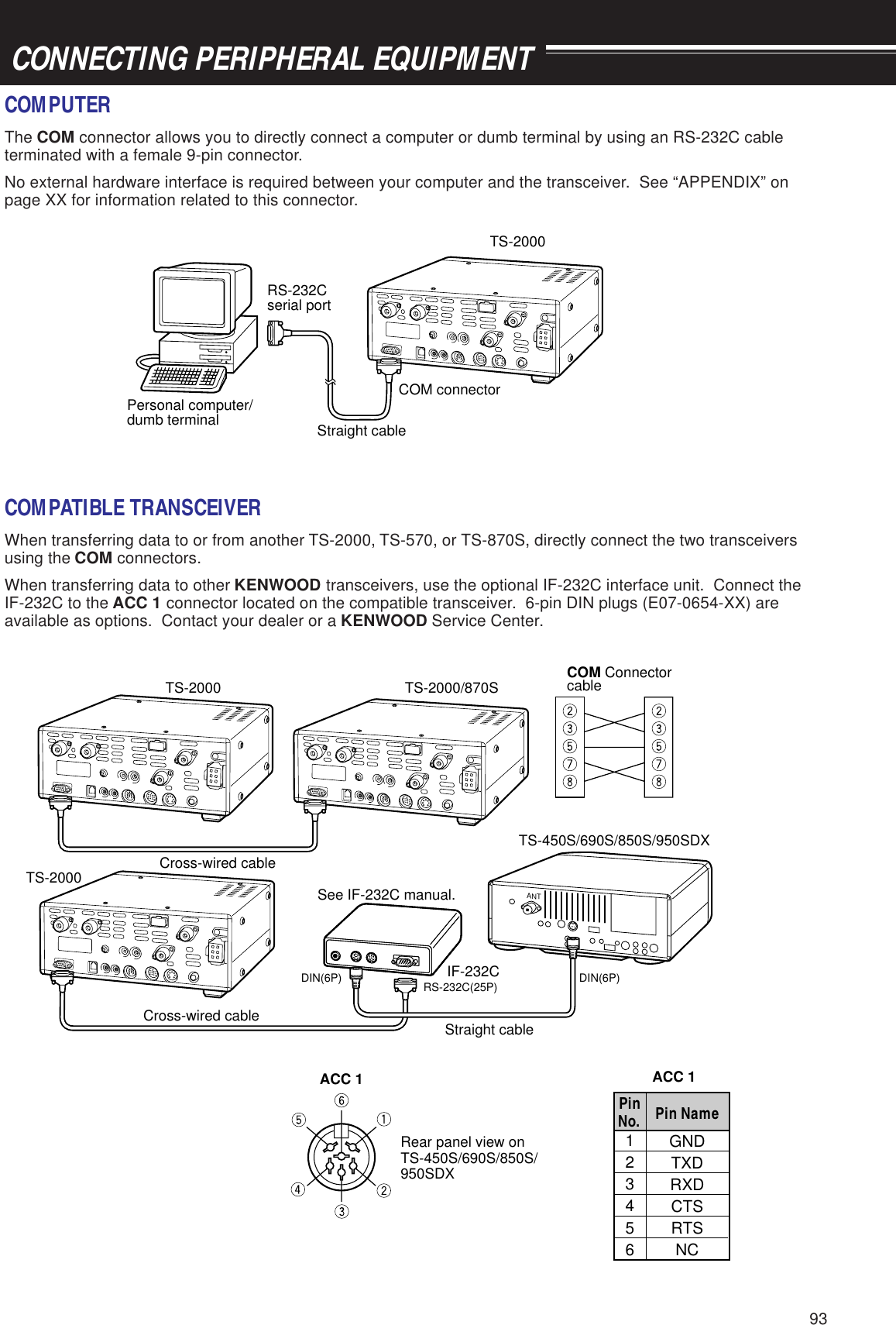
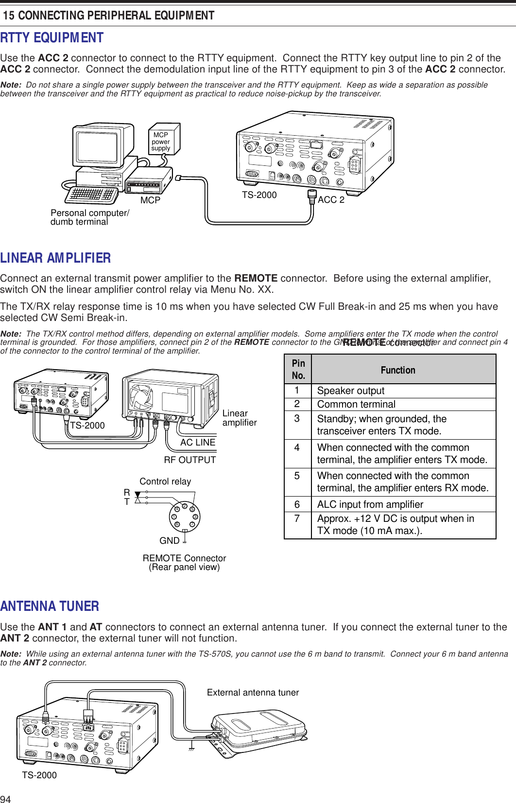
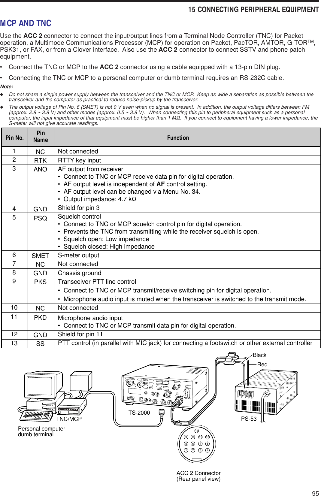
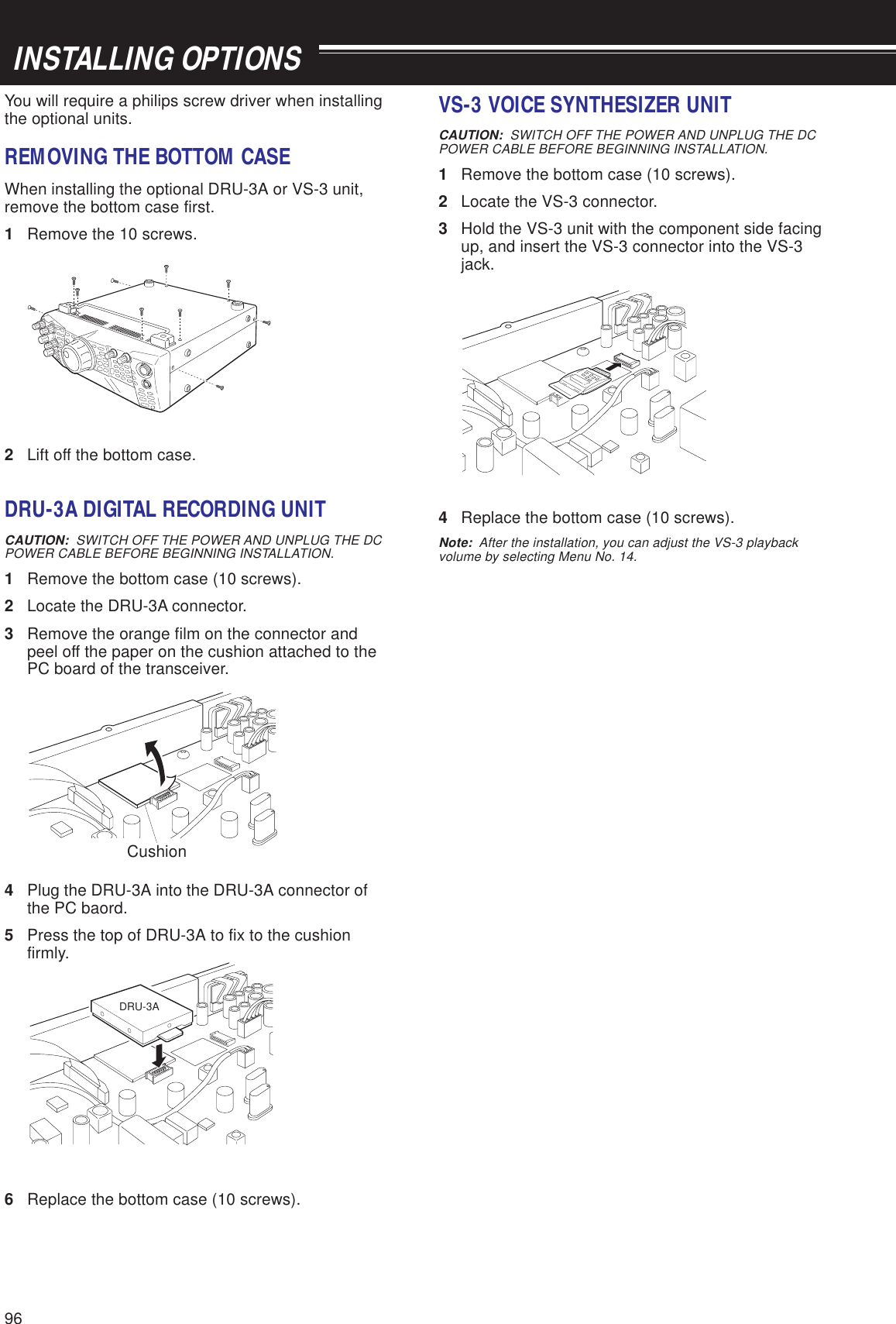
![991Switch ON the DC power supply.2Inspect the power cable. Confirmpolarities are correct.Red: positive (+); Black: negative (–)3Confirm the connections to the DCpower supply are secure.4Look for the cause of the blown fuse.After inspecting and correcting anyproblems, install a new fuse of thespecified rating.1Correct the input voltage or use a 12to 16 V battery.2Review “MICROPROCESSORRESET”. After understanding whatdata will be lost, do a Partial Reset.If the problem remains, do a FullReset.Have a new battery installed by yourdealer or at a KENWOOD ServiceCenter.1Review “WRITING CONVENTIONSFOLLOWED”.2Press [F.LOCK] to switch OFFfunction.3Review “MICROPROCESSORRESET”. After understanding whatdata will be lost, do a Partial Reset.If the problem remains, do a FullReset.4Stop operating the Tuning control,then press the appropriate buttons.Press [F.LOCK] to switch OFF function.1Change Menu No. 32 to OFF.2Turn the DSP SLOPE (LOW) controlcounterclockwise and the DSPSLOPE (HIGH) control clockwise.3Press [N.R.] to switch OFF function.4Press [B.C.] to switch OFF function. 16 MAINTENANCETROUBLESHOOTINGThe problems described in this table are commonly encountered operational malfunctions. These types ofdifficulties are usually caused by improper hook-up, accidental incorrect control settings, or operator error due toincomplete programming. These problems are usually not caused by circuit failure. Please review this table, andthe appropriate section(s) of this instruction manual, before assuming your transceiver is defective.Note:◆Due to frequency relationships of some circuits in this transceiver, beat tones may be heard on the following frequencies: 10.000 MHz,20.000 MHz and 30.000 MHz. This is not a fault.◆Placing a powered handy transceiver near this transceiver may cause noise in this transceiver.The transceiver willnot power up afterconnecting a13.8 V DC powersupply and pressing[POWER]. Nothingappears on thedisplay, and noreceiver noise isheard.After switching ON thepower, the transceiverdoes not functionnormally. Forexample, no digits orincorrect digits appearon the display.After switching ON thetransceiver,“14.000.00 MHz USB”appears and all datais lost; without doingFull Reset.The transceiver doesnot respond correctlyafter pressing buttonor key combinations,or turning controls perinstructions in thismanual.PageRef.XXXXXXXXXXiXXXXXXXProblem Probable Cause Corrective Action1DC power supply is OFF.2Faulty power cable3The power cable is not connectedsecurely.4Power cable fuse is open.1The input voltage is outside 13.8 VDC ±15% (11.7 to 15.8 V DC).2The microprocessor hasmalfunctioned.The backup lithium battery voltage istoo low.1Procedures are not being followedprecisely.2The Frequency Lock function isON.3The microprocessor and itsmemory need resetting.4The buttons on the transceiver areunavailable while operating theTuning control.The Frequency Lock function is ON.1The filter for digital operation isselected.2The DSP SLOPE (LOW) control orDSP SLOPE (HIGH) control wasincorrectly set.3Noise Reduction 1 or 2 is ON.4Beat Cancel is ON.The frequencycannot be changed.SSB audio quality isvery poor; the highor low audiofrequencies areabsent.XXXXXXXX](https://usermanual.wiki/JVC-KENWOOD/31201110/User-Guide-119445-Page-107.png)
![100 16 MAINTENANCE1The SQL control is fully clockwise.2The Attenuator function is ON.3 [SEND] was pressed, and thetransceiver is now in transmitmode.4Mic [PTT] is pressed.5The receive bandwidth wasincorrectly set.6The wrong antenna connector(ANT 1/ANT 2) was selected.7The receive preamplifier is OFF.The RF control was set too low.The wrong modulation mode wasselected.1The SQL control was not setcorrectly.2Less than two memory channelswere unlocked.3Less than two memory channelswere programmed.With Group Scan selected, thechannel you want to scan is in adifferent group.The start and end frequencies areidentical.The impedance of the coaxial cableand antenna was not matched.• Tuning does not successfully finishdepending on conditions althoughthe SWR meter indicates smallerthan 3:1.The SWR of the antenna system is toohigh.1The microphone plug was notinserted completely into the MICconnector.2The Transmit Inhibit function is ON.3CW or FSK was selected instead ofa voice mode.4The filter for digital operation wasselected.5The wrong antenna connector(ANT 1/ANT 2) was selected.No signals arereceived or receivesensitivity seemspoor.No signals arereceived or receivesensitivity seemspoor; S-meter isreading full scale.Received signals aretotally unintelligible.Memory Scan will notstart scanning.Memory Scan will notscan one of thestored channels; thedesired channel isNOT locked out.Program Scan willnot start scanning.Tuning does notfinish successfully.The internal tuner isbypassedimmediately aftertuning is started.You cannot transmiteven though youpress Mic [PTT] ortransmissions resultin no contacts.1Turn the SQL controlcounterclockwise.2Press [ATT] to switch OFF function.3Press [SEND] to return to receivemode.4Release Mic [PTT].5Review sections “IF FILTER” and“CHANGING RECEIVEBANDWIDTH”, and set the controlsaccordingly.6Press [ANT] to select the otherantenna connector.7Press [PRE-AMP] to switch ONfunction.Turn the RF control fully clockwise.Press [LSB/USB], [CW/FSK], or[FM/AM] to select the correctmodulation mode.1Adjust the SQL control to justeliminate background noise.2Unlock at least two memorychannels.3Store data in at least two memorychannels.Select the group that contains thememory channel you want to scan.Store different start and endfrequencies.Adjust the antenna system to lower theSWR.Adjust the antenna system to lower theSWR.1Turn OFF the power, ensure the MICconnector has no foreign objects init, then plug in the connector.Secure the connector with thelocking ring.2Change Menu No. 38 to OFF.3Press [LSB/USB] or [FM/AM] toselect a voice mode.4Change Menu No. 32 to OFF.5Press [ANT] to select the otherantenna connector.XXXXXXXXXX,,XXXXXXXXXXXXXXXXXXXXXXXXXXXXXXXX](https://usermanual.wiki/JVC-KENWOOD/31201110/User-Guide-119445-Page-108.png)