JVC KENWOOD 35753110 VHF FM Transceiver User Manual TK 690 790 890 C

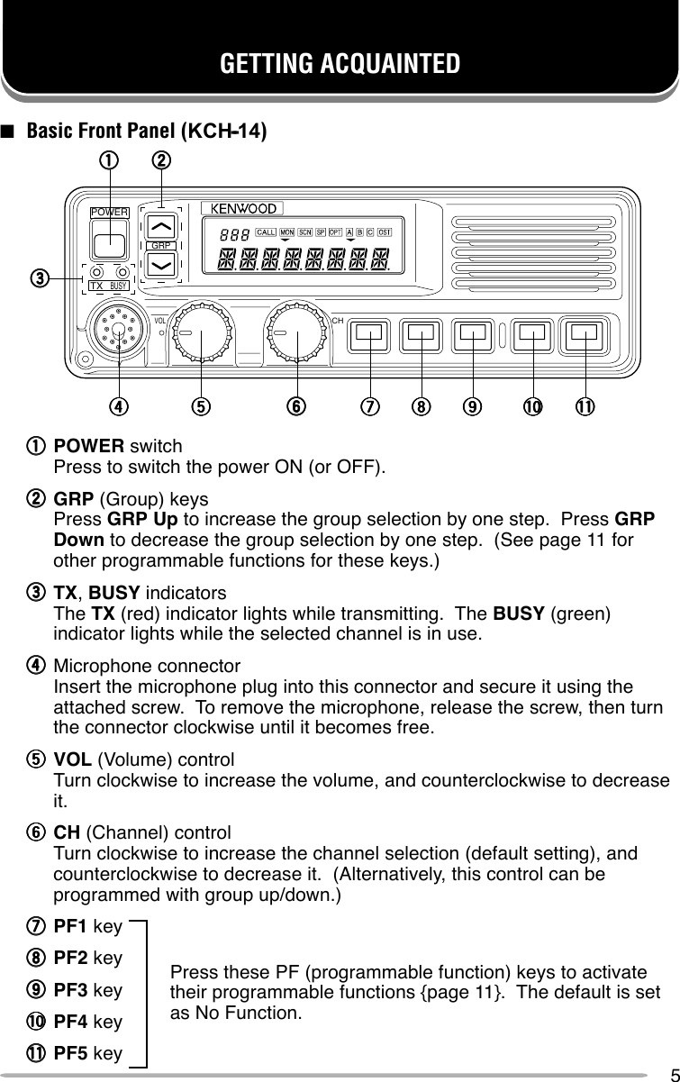
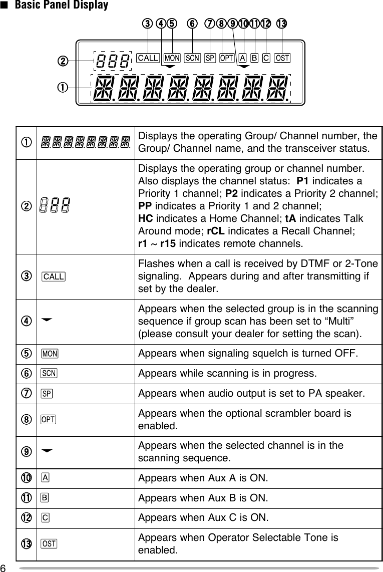
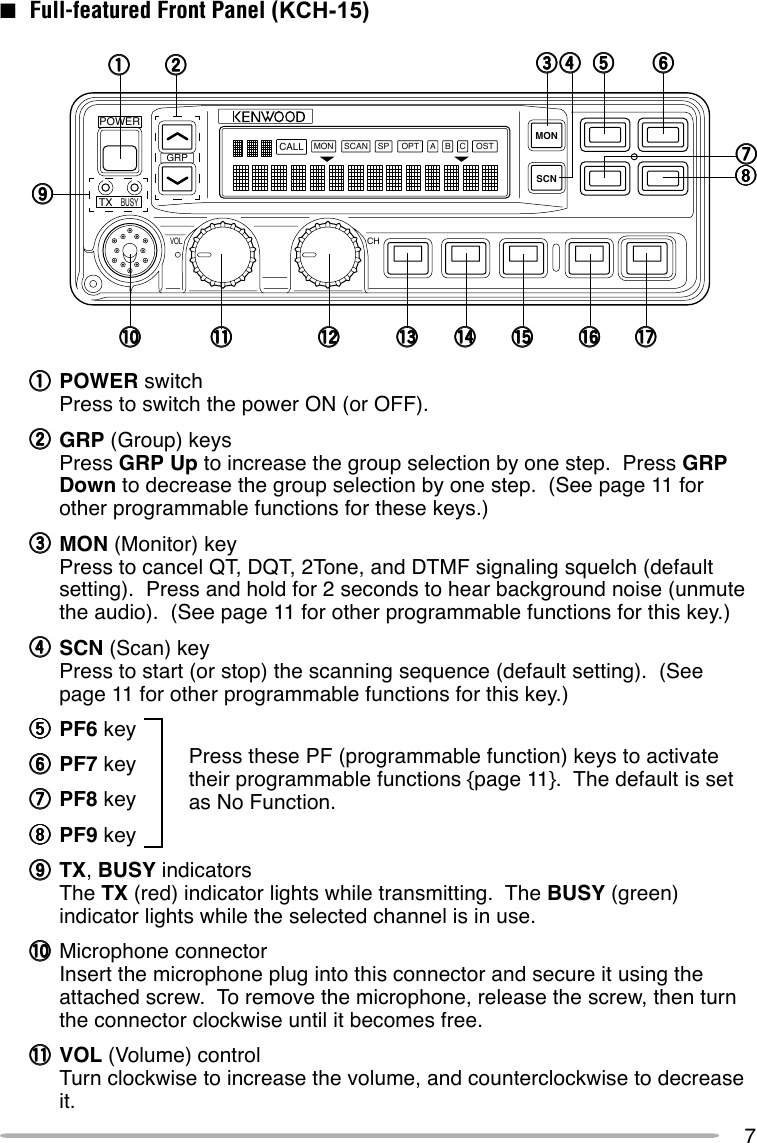
JVC KENWOOD Corporation VHF FM Transceiver TK 690 790 890 C

manual

TK-5710 seriesINSTRUCTION MANUALVHF FM TRANSCEIVERGRPPOWERTXVOLCHBUSYSCAN OPT OSTA B CMONCALLSPMONSCNGRPVOLCHPOWERTXBUSY
THANK YOU!We are grateful you chose KENWOOD for your land mobile applications.  Webelieve this easy-to-use transceiver will provide dependable communications tokeep personnel operating at peak efficiency.KENWOOD transceivers incorporate the latest in advanced technology.  As aresult, we feel strongly that you will be pleased with the quality and features ofthis product.MODELS COVERED BY THIS MANUAL•••••TK-5710:VHF FM Transceiver•••••TK-5710H:VHF FM Transceiver
iOne or more of the following statements may be applicable:FCC WARNINGThis equipment generates or uses radio frequency energy.  Changes or modifications to thisequipment may cause harmful interference unless the modifications are expressly approved in theinstruction manual.  The user could lose the authority to operate this equipment if an unauthorizedchange or modification is made.INFORMATION TO THE DIGITAL DEVICE USER REQUIRED BY THE FCCThis equipment has been tested and found to comply with the limits for a Class B digital device,pursuant to Part 15 of the FCC Rules.  These limits are designed to provide reasonable protectionagainst harmful interference in a residential installation. This equipment generates, uses and cangenerate radio frequency energy and, if not installed and used in accordance with the instructions,may cause harmful interference to radio communications.  However, there is no guarantee that theinterference will not occur in a particular installation.  If this equipment does cause harmfulinterference to radio or television reception, which can be determined by turning the equipment offand on, the user is encouraged to try to correct the interference by one or more of the followingmeasures:•Reorient or relocate the receiving antenna.•Increase the separation between the equipment and receiver.•Connect the equipment to an outlet on a circuit different from that to which the receiver isconnected.•Consult the dealer for technical assistance.◆GOVERNMENT LAW PROHIBITS THE OPERATION OF UNLICENSED RADIOTRANSMITTERS WITHIN THE TERRITORIES UNDER GOVERNMENT CONTROL.◆ILLEGAL OPERATION IS PUNISHABLE BY FINE OR IMPRISONMENT OR BOTH.◆REFER SERVICE TO QUALIFIED TECHNICIANS ONLY.SAFETY:  It is important that the operator is aware of, and understands, hazardscommon to the operation of any transceiver.WARNING!◆EXPLOSIVE ATMOSPHERES (GASES, DUST, FUMES, etc.)Turn OFF your transceiver while taking on fuel or while parked in a gasoline service station.  Donot carry spare fuel containers in the trunk of your vehicle if your transceiver is mounted in thetrunk area.◆INJURY FROM RADIO FREQUENCY TRANSMISSIONSDo not operate your transceiver when somebody is within two to three feet of the antenna, toavoid the possibility of radio frequency burns or related physical injury.◆DYNAMITE BLASTING CAPSTurn OFF your transceiver when in an area where blasting is in progress, or where “TURN OFFTWO-WAY RADIO” signs have been posted.  Operating the transceiver within 150 meters(500 feet) of dynamite blasting caps may cause them to explode.  If you are carrying blastingcaps in your vehicle, make sure they are enclosed in a metal box with a padded interior.  Do nottransmit while the caps are being placed into or are being removed from the container.Note:  This instruction manual covers only the basic functions of the transceiver.  Consult your dealerfor more detailed information.NOTICES TO THE USER
3WARNING!◆VARIOUS ELECTRONIC EQUIPMENT IN YOUR VEHICLE MAY MALFUNCTION IF THEY ARENOT PROPERLY PROTECTED FROM THE RADIO FREQUENCY ENERGY WHICH IS PRESENTWHILE TRANSMITTING.  ELECTRONIC FUEL INJECTION, ANTI-SKID BRAKING, AND CRUISECONTROL SYSTEMS ARE TYPICAL EXAMPLES OF EQUIPMENT THAT MAY MALFUNCTION.IF YOUR VEHICLE CONTAINS SUCH EQUIPMENT, CONSULT THE DEALER FOR THE MAKEOF VEHICLE AND ENLIST HIS AID IN DETERMINING IF THEY WILL PERFORM NORMALLYWHILE TRANSMITTING.◆ALTHOUGH THE REMOTE PANELS ARE WATER RESISTANT, THE MAIN TRANSCEIVER BODYIS NOT.  MOUNT IT IN A PLACE WHERE IT WILL NOT GET WET.Note:  The following preparation instructions are for use by your KENWOOD dealer, an authorizedKENWOOD service facility, or the factory.■Tools RequiredNote:  Before installing the transceiver, always check how far the mounting screws will extend belowthe mounting surface.  When drilling mounting holes, be careful not to damage vehicle wiring orparts.The following tools are required for installing the transceiver:•6 mm (1/4 inch) or larger electric drill•Drill bits (sizes listed below) and circle cutters■Power Cable ConnectionCAUTION:  THE TRANSCEIVER OPERATES IN 12 V NEGATIVE GROUND SYSTEMS ONLY!CHECK THE BATTERY POLARITY AND VOLTAGE OF THE VEHICLE BEFORE INSTALLING THETRANSCEIVER.1Check for an existing hole, conveniently located in the firewall, where thepower cable can be passed through.•If no hole exists, use a circle cutter to drill the firewall, then install a rubbergrommet.2Run the two power cable leads through the fire wall and into the enginecompartment, from the passenger compartment.3Connect the red lead to the positive (+) battery terminal and the black leadto the negative (–) battery terminal.•Locate the fuse as close to the battery as possible.4Coil and secure the surplus cable with the provided retaining band.•Be sure to leave enough slack in the cables so the transceiver can be removedfor servicing while keeping the power applied.PREPARATIONeziStiBllirD esopruP)hcni23/5(mm2.4swercsgnippat-flesmm61x5)hcni8/1(mm2.3swercsgnippat-flesmm61x4
4■Installing the TransceiverWARNING!  FOR PASSENGER SAFETY, INSTALL THE TRANSCEIVER SECURELY, USING THESUPPLIED MOUNTING BRACKET, SO THE TRANSCEIVER WILL NOT BREAK LOOSE IN THEEVENT OF A COLLISION.1Mark the position of the holes in the dash by using the mounting bracketas a template.  Drill the holes, then attach the mounting bracket using thesupplied 5 x 16 mm screws.•Be sure to mount the transceiver in a location where the controls will be withineasy reach of the user, and where there is sufficient space at the rear of thetransceiver for cable connections.2Connect the antenna and the supplied power cable to the transceiver.3Slide the transceiver into the mounting bracket and secure it using thesupplied hex-headed screws.4Mount the microphone hanger, using the supplied 4 x 16 mm screws, in alocation where it will be within easy reach of the user.•The microphone and microphone cable should be mounted in a place wherethey will not interfere with the safe operation of the vehicle.5Connect one plug of the microphone cable to the jack on the base of themicrophone, and the other plug to the microphone jack on the front panelof the transceiver.  Place the microphone on the hanger.MicrophonehangerMicrophoneMicrophone cableMounting bracketAntennaconnectorTransceiverPower inputconnectorPower cable BatteryFuse holderFuseHex headedscrewRed wireBlack wire
5GETTING ACQUAINTED■ Basic Front Panel (KCH--14)qqqqqPOWER switchPress to switch the power ON (or OFF).wwwwwGRP (Group) keysPress GRP Up to increase the group selection by one step.  Press GRPDown to decrease the group selection by one step.  (See page 11 forother programmable functions for these keys.)eeeeeTX, BUSY indicatorsThe TX (red) indicator lights while transmitting.  The BUSY (green)indicator lights while the selected channel is in use.rrrrrMicrophone connectorInsert the microphone plug into this connector and secure it using theattached screw.  To remove the microphone, release the screw, then turnthe connector clockwise until it becomes free.tttttVOL (Volume) controlTurn clockwise to increase the volume, and counterclockwise to decreaseit.yyyyyCH (Channel) controlTurn clockwise to increase the channel selection (default setting), andcounterclockwise to decrease it.  (Alternatively, this control can beprogrammed with group up/down.)uuuuuPF1 keyiiiiiPF2 keyoooooPF3 key!0!0!0!0!0 PF4 key!1!1!1!1!1 PF5 keyPress these PF (programmable function) keys to activatetheir programmable functions {page 11}.  The default is setas No Function.GRPVOLCHPOWERTXBUSYqqqqqwwwwweeeeerrrrrtttttyyyyyuuuuuiiiiiooooo!0!0!0!0!0 !1!1!1!1!1
6qqqqq eht,rebmunlennahC/puorGgnitarepoehtsyalpsiD.sutatsreviecsnartehtdna,emanlennahC/puorGwwwww.rebmunlennahcropuorggnitarepoehtsyalpsiD:sutatslennahcehtsyalpsidoslA 1P asetacidni;lennahc1ytiroirP 2P ;lennahc2ytiroirPasetacidniPP ;lennahc2dna1ytiroirPasetacidniCH ;lennahCemoHasetacidni At klaTsetacidni;edomdnuorA LCr ;lennahCllaceRasetacidni1r ~51r .slennahcetomersetacidnieeeeeenoT-2roFMTDybdeviecersillacanehwsehsalFfignittimsnartretfadnagnirudsraeppA.gnilangis.relaedehtybtesrrrrrgninnacsehtnisipuorgdetcelesehtnehwsraeppA”itluM“ottesneebsahnacspuorgfiecneuqes.)nacsehtgnittesrofrelaedruoytlusnocesaelp(ttttt .FFOdenrutsihcleuqsgnilangisnehwsraeppAyyyyy .ssergorpnisigninnacselihwsraeppAuuuuu .rekaepsAPottessituptuooiduanehwsraeppAiiiii sidraobrelbmarcslanoitpoehtnehwsraeppA.delbaneooooo ehtnisilennahcdetcelesehtnehwsraeppA.ecneuqesgninnacs0!0!0!0!0! .NOsiAxuAnehwsraeppA1!1!1!1!1! .NOsiBxuAnehwsraeppA2!2!2!2!2! .NOsiCxuAnehwsraeppA3!3!3!3!3! sienoTelbatceleSrotarepOnehwsraeppA.delbane■Basic Panel Displayeeeeeqqqqqtttttyyyyyuuuuuiiiii!0!0!0!0!0!1!1!1!1!1!2!2!2!2!2 !3!3!3!3!3rrrrrooooowwwww
7■ Full-featured Front Panel (KCH-15)qqqqqPOWER switchPress to switch the power ON (or OFF).wwwwwGRP (Group) keysPress GRP Up to increase the group selection by one step.  Press GRPDown to decrease the group selection by one step.  (See page 11 forother programmable functions for these keys.)eeeeeMON (Monitor) keyPress to cancel QT, DQT, 2Tone, and DTMF signaling squelch (defaultsetting).  Press and hold for 2 seconds to hear background noise (unmutethe audio).  (See page 11 for other programmable functions for this key.)rrrrrSCN (Scan) keyPress to start (or stop) the scanning sequence (default setting).  (Seepage 11 for other programmable functions for this key.)tttttPF6 keyyyyyyPF7 keyuuuuuPF8 keyiiiiiPF9 keyoooooTX, BUSY indicatorsThe TX (red) indicator lights while transmitting.  The BUSY (green)indicator lights while the selected channel is in use.!0!0!0!0!0 Microphone connectorInsert the microphone plug into this connector and secure it using theattached screw.  To remove the microphone, release the screw, then turnthe connector clockwise until it becomes free.!1!1!1!1!1 VOL (Volume) controlTurn clockwise to increase the volume, and counterclockwise to decreaseit.Press these PF (programmable function) keys to activatetheir programmable functions {page 11}.  The default is setas No Function.GRPPOWERTXVOLCHBUSYSCAN OPT OSTA B CMONCALLSPMONSCNqqqqqwwwwwooooo!0!0!0!0!0 !1!1!1!1!1rrrrreeeeeiiiiitttttuuuuuyyyyy!2!2!2!2!2 !3!3!3!3!3 !4!4!4!4!4 !5!5!5!5!5 !6!6!6!6!6 !7!7!7!7!7
8!2!2!2!2!2 CH (Channel) controlTurn clockwise to increase the channel selection (default setting), andcounterclockwise to decrease it.  (Alternatively, this control can beprogrammed with group up/down.)!3!3!3!3!3 PF1 key!4!4!4!4!4 PF2 key!5!5!5!5!5 PF3 key!6!6!6!6!6 PF4 key!7!7!7!7!7 PF5 keyPress these PF (programmable function) keys to activatetheir programmable functions {page 11}.  The default is setas No Function.
9■Full-featured Panel Displayqqqqq eht,rebmunlennahC/puorGgnitarepoehtsyalpsiD.sutatsreviecsnartehtdna,emanlennahC/puorGwwwww.rebmunlennahcropuorggnitarepoehtsyalpsiD:sutatslennahcehtsyalpsidoslA 1P asetacidni;lennahc1ytiroirP 2P ;lennahc2ytiroirPasetacidniPP ;lennahc2dna1ytiroirPasetacidniCH ;lennahCemoHasetacidni AT klaTsetacidni;edomdnuorA LCR ;lennahCllaceRasetacidni1R ~51R .slennahcetomersetacidnieeeeeenoT-2roFMTDybdeviecersillacanehwsehsalFfignittimsnartretfadnagnirudsraeppA.gnilangis.relaedehtybtesrrrrrgninnacsehtnisipuorgdetcelesehtnehwsraeppA”itluM“ottesneebsahnacspuorgfiecneuqes.)nacsehtgnittesrofrelaedruoytlusnocesaelp(ttttt .FFOdenrutsihcleuqsgnilangisnehwsraeppAyyyyy .ssergorpnisigninnacselihwsraeppAuuuuu .rekaepsAPottessituptuooiduanehwsraeppAiiiii sidraobrelbmarcslanoitpoehtnehwsraeppA.delbaneooooo .NOsiAxuAnehwsraeppA0!0!0!0!0! .NOsiBxuAnehwsraeppA1!1!1!1!1! .NOsiCxuAnehwsraeppA2!2!2!2!2! ehtnisilennahcdetcelesehtnehwsraeppA.ecneuqesgninnacs3!3!3!3!3! sienoTelbatceleSrotarepOnehwsraeppA.delbaneSCAN OPT OSTA B CMONCALLSPeeeeeqqqqqtttttyyyyyuuuuuiiiii!0!0!0!0!0 !1!1!1!1!1 !2!2!2!2!2!3!3!3!3!3rrrrrooooowwwwwCALLMONSCANSPOPTABCOST
109 pin connector(for accessories)Power inputconnector■Rear Panel■MicrophonePTT (Push To Talk) switchPress and hold to transmit, then speak intothe microphone.  Release to receive.25 pin connector(for accessories)Antenna connector
11PROGRAMMABLE FUNCTIONSThe following functions can be programmed onto the GRP Up, GRP Down,MON, SCN, and PF1 ~ PF9 keys.  If desired, you do not need to have a functionprogrammed onto a key (No Function).  Please contact your dealer for moreinformation on these functions.      (Channel Up/ Group Up)      (Channel Down/ Group Down)Press these keys to increase or decrease the channel number or groupnumber (respectively).  Pressing the key momentarily will change the numberby 1 step.  Pressing and holding the key will scroll through the numbers.AN (Channel Name)Press this key to switch the display between the Group/ Channel number, andthe Group/ Channel name (alphanumeric).  A tone will sound each time youswitch between numerical and alphanumerical display.AUX A/ AUX B/ AUX CPress these keys to turn the Aux A, Aux B, or Aux C output port (respectively)ON or OFF.  When you press the key, the AUX A, AUX B, or AUX C iconappears and a tone sounds.  When you press the key again, the icondisappears and a tone sounds.CH 1 (CH 1 Direct)/ CH 2 (CH 2 Direct)/ CH 3 (CH 3 Direct)/ CH 4 (CH 4 Direct)/CH 5 (CH 5 Direct)Press these keys to directly select the Group 1/ Channel 1 directory, Group 1/Channel 2 directory, Group 1/ Channel 3 directory, Group 1/ Channel 4directory, or Group 1/ Channel 5 directory (respectively).D/A (Delete/ Add)Press this key to delete a channel/ group from, or add a channel/ group to,the scanning sequence.Press this key to add the currently displayed channel to scan.  The channeladd icon appears.  Press and hold this key for 2 seconds to add the currentlydisplayed group to scan.  The group add icon appears.If a channel is already in the scanning sequence, and you want to delete it,press this key while the channel is displayed.  The channel add icondisappears.  If a group is already in the scanning sequency, and you want todelete it, press and hold this key for 2 seconds.  The group add icondisappears.Press this key while scanning when an undesired channel is displayed, totemporarily delete it from scan.  If there are only 2 channels in the scanningsequence, this function cannot be performed.  To restore the original scanningsequence, turn scan OFF, then ON.
12DIM (Dimmer)Press this key to adjust the brightness of the display and key backlight.  Alsopress this key to turn the TX and BUSY indicators and the DTMF microphonekeypad backlight ON or OFF.EMG (Emergency Call)Press this key to initiate an emergency call (requires ANI board).  When anemergency call is made, no tone is emitted and the display does not change.To end the emergency call, turn the transceiver power OFF.HA (Horn Alert)Press this key to turn the Horn Alert function ON or OFF.  If you receive a callfrom the base station with 2Tone or DTMF signaling, horn alert will activate.When you turn Horn Alert ON, a tone will sound and HA (or HORN ALERT)appears on the display.HC (Home Channel: fixed/ toggle)Fixed:  Press this key to select the pre-programmed Home Channel.Toggle:  Press this key to select the pre-programmed Home Channel.  Pressit again to return to the previous channel.  If used while scanning, pressingthis key a second time will change to the revert channel.IC (Intercom)This feature requires dual head configuration.  Press this key to turn theintercom feature ON or OFF.  While ON, you can press the PTT switch tocommunicate to another control head operator without transmitting over theair.  When you press this key, a tone sounds and INTERCOM appears on thedisplay.  The intercom can be used even while scanning and receiving a call.MON (Monitor)Press this key to cancel QT/DQT and 2-Tone/DTMF signaling squelch.  Pressand hold this key for 2 seconds to hear background noise (unmute the audio).When monitor is being used, the MON icon appears on the display.OPT (Scrambler)If you have an optional scrambler board installed in your transceiver, you canpress this key to turn it ON or OFF.  When enabled, a tone sounds and theOPT icon appears on the display.  To change the scrambler code:1Press and hold the OPT key for 1 second.  A tone sounds and CODEappears on the display with the current code.2Press the GRP Up/ Down keys, or use the CH control to select thedesired setting.3Press the OPT key.  A tone sounds and the display returns to the normalchannel.
13OST (Operator Selectable Tone)This feature allows you to select a signaling tone from the pre-programmedQT/DQT list.  Press this key to activate OST.  The OST icon appears on thedisplay.  To select a decode/encode pair:1Press and hold the OST key for 1 second.  A tone sounds.2Press the GRP Up/ Down keys, or use the CH control to select thedesired decode/encode pair.  TONE and the tone number or OST and theOST name appear on the display.3Press the OST key.  A tone sounds and the display returns to the normalchannel.PA (Public Address)Press this key to use the transceiver as a PA amplifier.  When you enable thisfunction, a tone sounds and PA (or PUBLIC ADDRESS) appears on thedisplay.  The public address can be used even while scanning and receiving acall.RCL (Channel Recall)During scan, you can press this key to select the last called channel.  rCL (orRCL) will appear on the display.  Press this key a second time to return to theprevious channel.SCN (Scan)Press this key to start or stop the scanning sequence.  When you activatescan, a tone sounds, the SCN (or SCAN) icon appears, and SCAN or theOFF HOOK revert channel number appears on the display.  If there is lessthan 2 channels in the scanning sequence, an error tone sounds.  Scan canbe set up two different ways:  ON HOOK or OFF HOOK.  ON HOOK requiresthe microphone to be on the hook before scanning will activate.  OFF HOOKallows you to activate scan whether the microphone is on or off the hook.When a signal is received while scanning, the scan will halt, the audio isunmuted, and the channel number or name appears on the display.If Priority1 or Priority2 is programmed, this priority channel is periodicallychecked for a signal while a signal is being received on a normal channel.When a signal appears on the priority channel, the transceiver willautomatically switch to that channel.If Priority1 and Priority2 are programmed, the Priority1 channel takesprecedence.  The transceiver acts the same as if there is one priority channelexcept that it checks both priority channels rather than a single channel.  Also,if a signal is being received on the Priority2 channel, the Priority1 channel isstill periodically checked for a signal.To enter carrier squelch scan, press the MON key while scan is in progress.
14SP (Speaker Internal/ External)Press this key to switch between “Internal” and “External” speaker.  When“External” is selected, a tone sounds and the SP icon appears on the display.You can use this function while scanning and receiving a call.  However, allaudio will be emitted from the PA speaker.SPM (Speaker 1-2 Mute)This feature requires dual head configuration.  Press this key to disable thespeaker audio from the other control head.  When pressed, a tone soundsand MUTE appears on the display with the muted head number.SQ (Squelch Level)You can manually adjust the squelch level using this function:1Press the SQ key.  A tone sounds and SQL (or SQUELCH) appears on thedisplay with the current squelch level.2Press the GRP Up/ Down keys, or use the CH control to select thedesired level.3Press the SQ key.  A tone sounds and the display returns to the normalchannel.TA (Talk Around)Press this key to make a call without using a repeater.  When you activate thisfunction, a tone sounds and tA (or TA) appears on the 3-digit display.  Thisfunction is useful when you are close to the mobiles you want to talk to.
15■Switching Power ON/ OFFPress the POWER switch to switch the transceiver ON (or OFF)•The display backlight illuminates when the power is switched ON.■Adjusting the VolumeTurn the VOL control clockwise to increase the volume, and counterclockwiseto decrease it.■Selecting a GroupPress the Group Up or Group Down keys, or use the CH control (dependingon which one is programmed with the group functions).•Pressing Group Up or Group Down will increase or decrease the group selection.•Turning the CH control clockwise will increase the group selection, and turning itcounterclockwise will decrease the selection.■Selecting a ChannelPress the Channel Up or Channel Down keys, or use the CH control(depending on which one is programmed with the channel functions).•Pressing Channel Up or Channel Down will increase or decrease the channelselection.•Turning the CH control clockwise will increase the channel selection, and turning itcounterclockwise will decrease the selection.■Making a Call1Select the desired group and channel (above).•Make sure the channel is not in use.  If the channel is in use, the BUSY (green)indicator will light; wait until the channel is no longer in use.2Press the PTT switch, then speak into the microphone in your normalspeaking voice.•For best results, hold the transceiver approximately 3 to 4 cm (1 1/2 inches)from your lips.3Release the PTT switch to receive.4Replace the microphone on the hanger when the call is finished.BASIC OPERATIONS
16DTMF CALLSYou can make DTMF calls using the optional KMC-28 DTMF microphone.■Manual DialingTo dial a number manually:1Press and hold the PTT switch.•If Keypad Auto PTT is enable, you do not need to press the PTT switch (pleaseconsult your dealer for enabling this function).2Press the desired DTMF keys.■RedialingA maximum of 16 digits can be redialed.  The last number dialed, eithermanually or automatically, will be redialed.To redial a number:1Press the     key.•An “A” will appear on the display.2Press the 0 key.•The transceiver will redial the last number, and the digits will appear on thedisplay.Note:  If the transceiver power is switched OFF, the redial memory will be erased.■Auto DialingNote:  Auto dialing is either enabled or disabled by your dealer.Store:To store a number in memory:1Press the # key.•A “D” will appear on the display.2Press the desired DTMF keys to enter a maximum of 16 digits.•Press and hold the PTT switch, then press 2, 5, 8, 0,     , or # to enter A, B, C,D,     , or # (respectively).3Press the # key.4Select the desired memory channel by pressing a DTMF key (1 ~ 9).•The number entered in step 2 will be stored in the memory channel selected.
17Confirm:To confirm a stored number:1Press the # key.•A “D” will appear on the display.2Press the     key.•“D–” will appear on the display.3Press the memory channel key (1 ~ 9) with the stored number you want toconfirm.•The stored digits will appear on the display and the DTMF tones will sound.Send:To send a stored number:1Press the     key.•An “A” will appear on the display.2Press the memory channel key (1 ~ 9) with the stored number you want tosend.•The transceiver will begin the transmission and the digits will appear on thedisplay.Clear:To erase a stored number from memory:1Press the # key.•A “D” will appear on the display.2Press the # key again.•“D–CLR” will appear on the display.3Press the memory channel key (1 ~ 9) with the stored number you want toerase.
18OTHER TRANSCEIVER FUNCTIONSThe following functions can be set up by your dealer.■Time-out Timer (TOT)The TOT is used to automatically inhibit transmission after a specified timeelapses.  If the PTT switch is held down for longer than the programmed time,the transceiver will stop transmitting and a warning tone will sound.  To stopthe warning tone, release the PTT switch.■Busy Channel Lockout (BCL)BCL prevents you from interfering with other stations that may be using thesame channel as you.  When you press the PTT switch while the channel is inuse, a warning tone sounds and the transceiver does not transmit.  To stopthe warning tone, release the PTT switch.If BCL override has been enabled, you can press the PTT switch again within0.5 seconds to cancel BCL.  The transceiver will transmit.■Operator Selectable Priority ChannelYou can set Priority1 and Priority2 channels when this function is enabled.  Toset a Priority1 channel, press and hold the SCN key, then press the MON key3 times.  To set a Priority2 channel, press and hold the SCN key, then pressthe MON key 2 times.■2-Tone/ DTMF Signaling2-Tone/ DTMF signaling will only open the squelch when the proper code isreceived.  When the transceiver receives a correct code, the CALL iconflashes.If transpond has been enabled, the transceiver automatically sends anacknowledgement signal after receiving the 2-Tone/ DTMF signal.If alert tone has been enabled, an alert tone sounds after receiving the2-Tone/ DTMF signal.
19■Roll Over/ Dead EndIf roll over is enabled and you are pressing the GRP Up/ Down keys, orrotating the CH control, when you reach the maximum or minimum number,the number will roll over to the minimum or maximum number.  For example,when turning the CH control clockwise, the channel number increases.When it reaches its maximum value, it rolls over to its minimum value andthen starts to increase again.If dead end is selected, when you reach the maximum or minimum value, thevalue will not change.  For example, when turning the CH control clockwise,the channel number increases.  When it reaches its maximum value, it stops.You must then rotate the CH control counterclockwise to change the value.■Dead Beat Disable (DBD)After receiving a DBD code, the transceiver will automatically send anacknowledgement signal.  Transmission is disabled.  If the radio receives aDBD reset code, the transceiver will automatically send an acknowledgementsignal.  Transmission is enabled.■Timed Power OFFThis function requires an ignition-sense which must be connected to the 9 pinconnector on the rear panel of the transceiver.  When you turn the ignition ofyour vehicle OFF, the timer starts.  After the pre-selected time expires, thetransceiver will turn OFF.  The timer resets when the ignition is turned ON andOFF.
  MANDATORY SAFETY INSTRUCTIONS TO INSTALLERS AND USERS  • Use only manufacturer or dealer supplied antenna. • Antenna Minimum Safe Distance: 180 cm (6 feet), 50% duty Cycle. • Antenna Gain: 0 dBd referenced to a dipole.  The Federal Communications Commission has adopted a safety standard for human exposure to RF (Radio Frequency) energy which is below the OSHA (Occupational Safety and Health Act) limits.  • Antenna Mounting: The antenna supplied by the manufacturer or radio dealer must not be mounted at a location such that during radio transmission, any person or persons can come closer than the above indicated minimum safe distance to the antenna, i.e. 180 cm (6 feet) , 50% duty Cycle. • To comply with current FCC RF Exposure limits, the antenna must be installed at or exceeding the minimum safe distance shown above, and in accordance with the requirements of the antenna manufacturer or supplier. • Vehicle installation: The antenna can be mounted at the center of a vehicle metal roof or trunk lid, if the minimum safe distance is observed. • Base Station Installation: The antenna should be fixed-mounted on an outdoor permanent structure. RF Exposure compliance must be addressed at the time of installation.  Antenna substitution: Do not substitute any antenna for the one supplied or recommended by the manufacturer or radio dealer. You may be exposing person or persons to excess radio frequency radiation. You may contact your radio dealer or the manufacturer for further instructions.     Maintain a separation distance from the antenna to person(s) of at least 180 cm (6 feet) , 50% duty Cycle.   “This transmitter is authorized to operate with a maximum duty factor of 50%, in typical push-to-talk mode, for satisfying FCC RF exposure compliance requirements.”  You, as the qualified end-user of this radio device must control the exposure conditions of bystanders to ensure the minimum separation distance (above) is maintained between the antenna and nearby persons for satisfying RF Exposure compliance. The operation of this transmitter must satisfy the requirements of Occupational/Controlled Exposure Environment, for work-related use, transmit only when person(s) are at least the minimum distance from the properly installed, externally mounted antenna. Transmit only when people outside the vehicle are at least the recommended minimum lateral distance away from the antenna/vehicle.

Navigation menu