JVC KENWOOD 36023120 VHF FM Transceiver User Manual
JVC KENWOOD Corporation VHF FM Transceiver Users Manual
UserManual.wiki
>
JVC KENWOOD
>
36023120 User Manual
>
Users Manual
Contents
1.
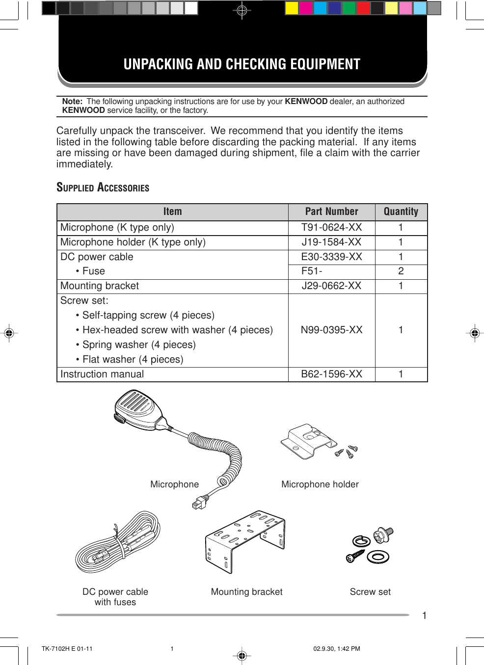
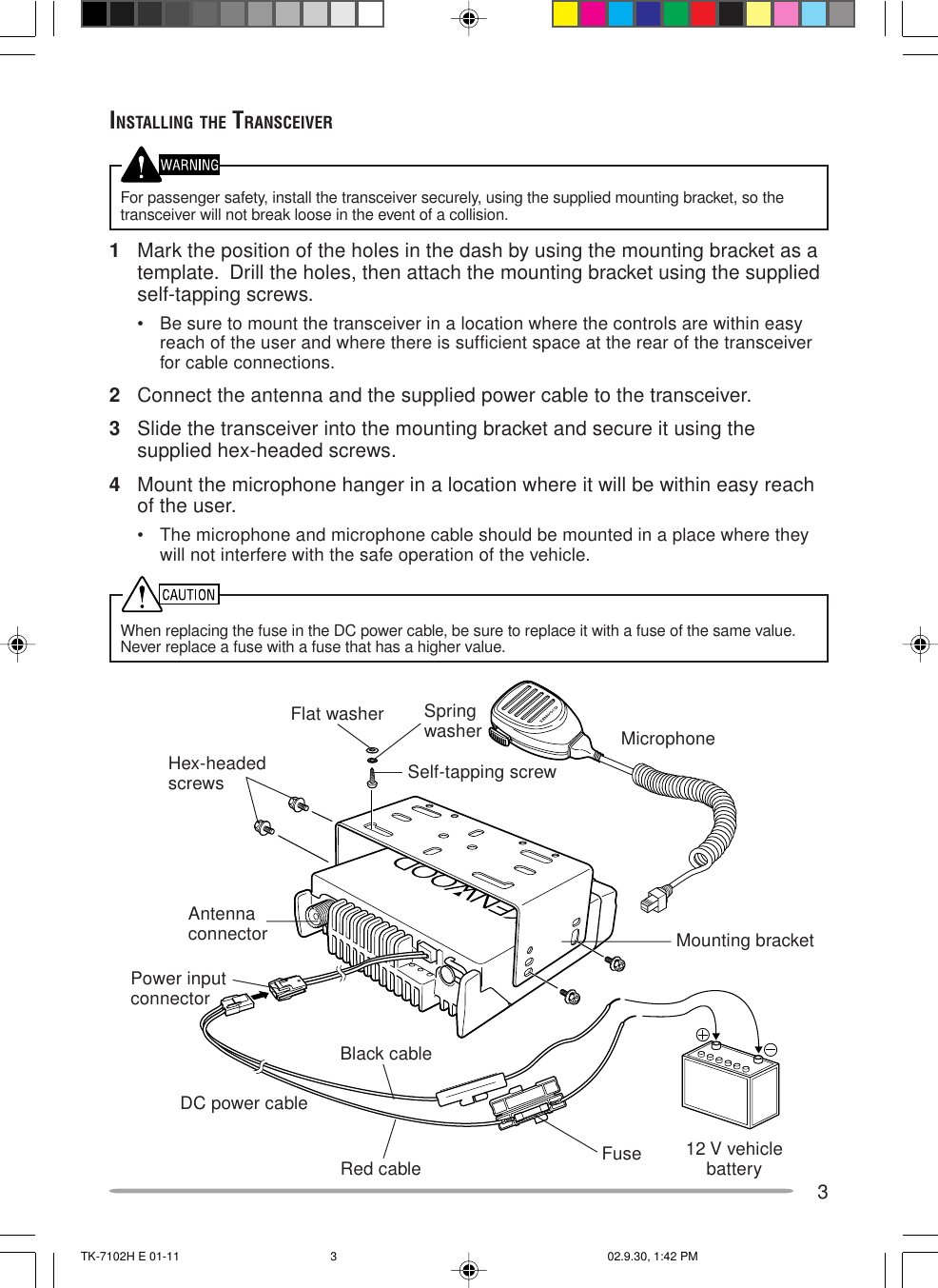
Users Manual
2.
Users Manual per CRN 10486
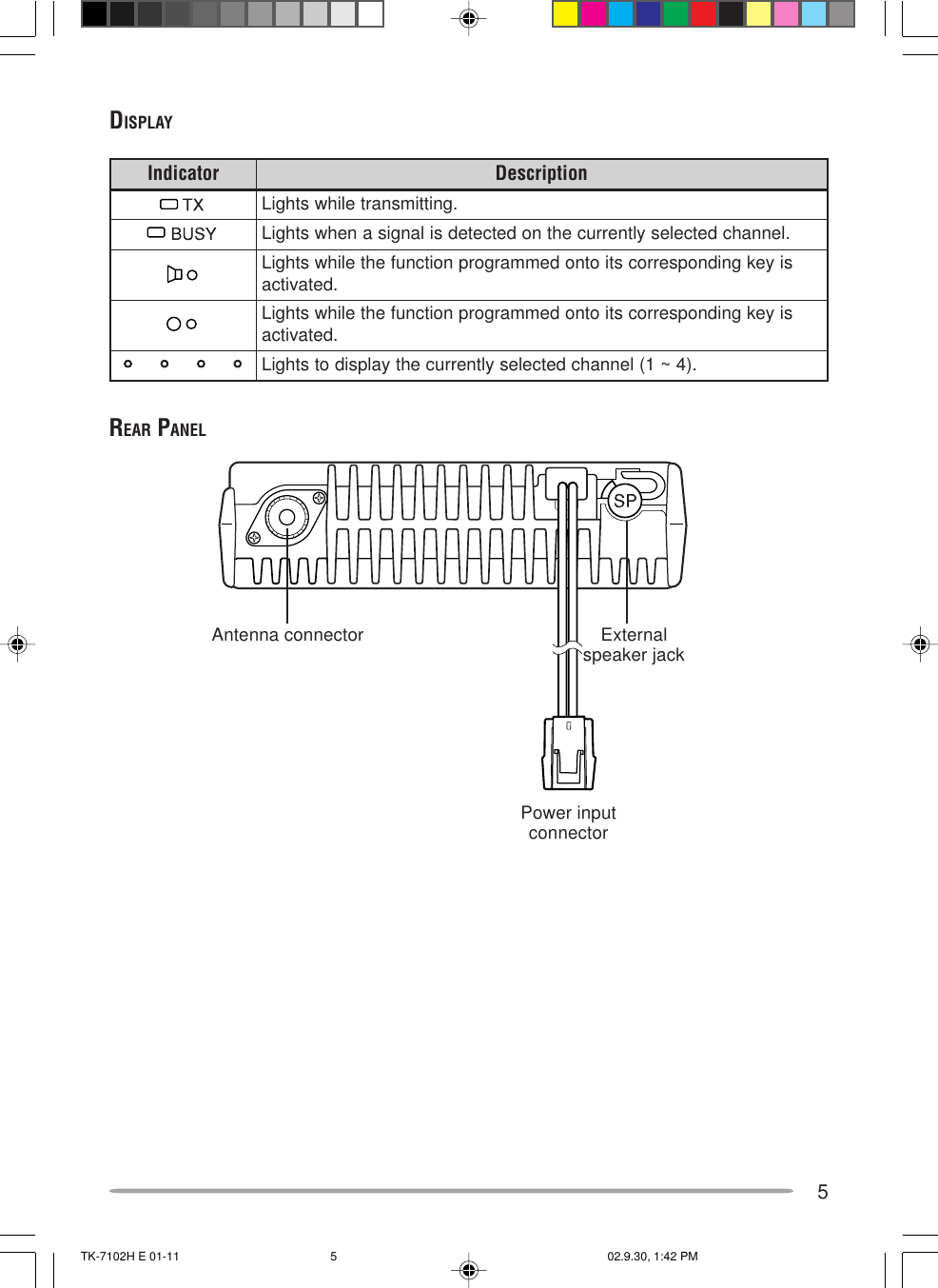
Users Manual
Navigation menu
Upload a User Manual
Namespaces
Wiki Guide
HTML
PDF
Info
Views
User Manual
Discussion / Help
Navigation