JVC KENWOOD 37144110 UHF Digital Repeater User Manual INSTALLATION
JVC KENWOOD Corporation UHF Digital Repeater INSTALLATION
Users Manual

Model: TKR-5800
FCC ID: K4437144110
INSTRUCTION MANUAL
TKR-5800
FEATURES
•The transmitting unit, the receiving unit, and the controller unit are contained in the same case of height 1U.
•TKR-5800 has two modulation mode of analog and digital.
•Alone, it functions as an analog conventional repeater or digital conventional repeater.
•If an analog trunking controller is connected outside, it will function as repeater for the analog sites.
And if two or more repeater is connected, it will function as a trunking system.
•The transmission system in digital mode is as follows.
●modulation method :4 Level FSK
●channel interval :6.25kHz
●Transmission rate :4800bps
●voice CODEC :AMBE+2(3600bps)
•The transmission system in analog mode is as follows.
●modulation method :FM
●channel interval :12.5kHz
•An air protocol adopts the original protocol of Kenwood.
PRECAUTIONS
• Do not expose the unit to rain or moisture; to prevent fire or electric shock.
• Do not open the unit under any circumstances; to avoid risk of electric shock.
• Do not expose the unit to long periods of direct sunlight, nor place it close to heating appliances.
• Do not place the unit in excessively dusty and/or humid areas, nor on unstable surfaces.
• If you detect an abnormal odor or smoke coming from the unit, disconnect the power from the unit immediately.
NOTICES TO THE USER
FCC WARNING
This equipment generates or uses radio frequency energy. Changes or modifications to this equipment may
cause harmful interference unless the modifications are expressly approved in the instruction manual. The user
could lose the authority to operate this equipment if an unauthorized change or modification is made.
** GOVERNMENT LAW PROHIBITS THE OPERATION OF UNLICENSED RADIO TRANSMITTERS
WITHIN THE TERRITORIES UNDER GOVERNMENT CONTROL.
** ILLEGAL OPERATION IS PUNISHABLE BY FINE OR IMPRISONMENT OR BOTH.
** REFER SERVICE TO QUALIFIED TECHNICIANS ONLY.
CAUTION: This repeater is intended for use as a fixed base station with the antenna located outdoors on the
rooftop or on antenna tower.
Model: TKR-5800
FCC ID: K4437144110
INSTALLATION
To install the handles onto the front panel of the repeater, align the handles with the holes on the front panel, then
secure the handles using the supplied screws.
MICROPHONE
Connect an optional KMC-30, KMC-27A, KMC-27B, or KMC-9C KENWOOD microphone to the MIC jack on the front
panel.
CONTROLS AND FUNCTIONS
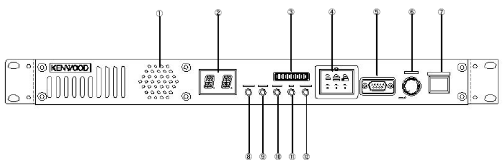
** Front Panel
①Speaker
②CH Number Display
Two 17-segment digits display the channel number or status.
③StatusDisplay
Eight LEDs display the status.
④Programmable Function keys
Press these keys to activate their programmable functions
⑤for maintenance purpose only
⑥VOLUME control
Rotate to adjust the volume.
⑦Mic jack
Connect a microphone to this 8-pin modular jack.
⑧CONT indicator
When assigned to a control channel, it lights red.
⑨OCXO indicator
The state of OCXO is displayed in green and red.
⑩BUSY indicator
Lights green while a signal is being received.
⑪TX indicator
Lights red while transmitting.
⑫Power indicator
Lights green when power is applied from the DC 13.8V jack.
Model: TKR-5800
FCC ID: K4437144110
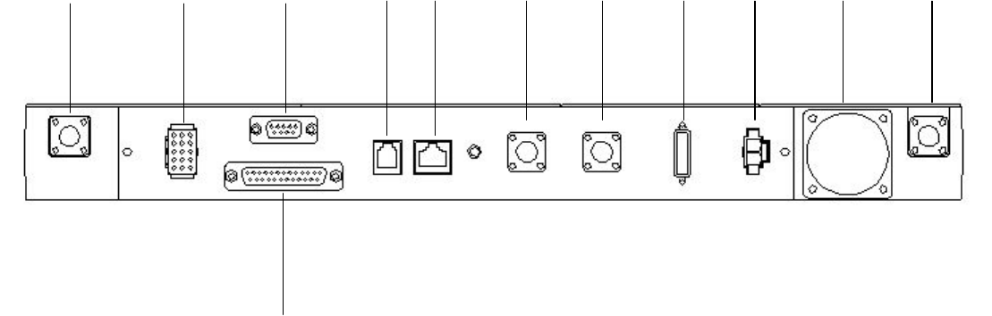
** Rear Panel
① ② ③ ④ ⑤ ⑥ ⑦ ⑧ ⑨ ⑩ ⑪
⑫
①RX IN jack
Connect a RX antenna or a duplexer to this BNC receptacle.CH Number Display
②TEST/SPKR jack
Test input/output jack. Connect an external speaker to this jack.
③④⑤⑥⑦for maintenance purpose only
⑧FUSE
Insert 4A blade fuses into these fuse holders
⑨DC 13.8V jack
Connect a 13.8 V DC power supply to this jack.
Supplied cable with ferrite core must be used
⑩Cooling Fan
It is used in order to radiate heat.
⑪TX OUT jack
Connect a TX antenna or a duplexer ti this receptacle
⑫for maintenance purpose only
REPEATER OPERA TION
When power is applied to the unit, the POWER indicator lights.
• Green when using the main DC jack.
Rotate the VOLUME control to adjust the volume.
The BUSY indicator lights green while receiving a signal and the TX indicator lights red while transmitting.
TRANSCEIVER OPERA TION
** Receive
Adjust the volume to your desired level.
You may need to readjust the volume when you receive a message from your dispatcher or another member in your
fleet.
• The BUSY indicator lights green while a signal is being received.
** Transmit
1 Listen to the channel before transmitting, to make sure it is not being used.
2 Press the microphone PTT switch, then speak in your normal speaking voice.
• The TX indicator lights red while transmitting.
3 When you finish speaking, release the PTT switch.
Model: TKR-5800
FCC ID: K4437144110
MANDATORY SAFETY INSTRUCTIONS TO INSTALLERS AND USERS
• Use only manufacturer or dealer supplied antenna.
• Antenna Minimum Safe Distance: 60 cm (2 feet), 50% duty Cycle.
• Antenna Gain: 0 dBd referenced to a dipole.
The Federal Communications Commission has adopted a safety standard for human
exposure to RF (Radio Frequency) energy which is below the OSHA (Occupational Safety
and Health Act) limits.
• Antenna Mounting: The antenna supplied by the manufacturer or radio dealer must not be
mounted at a location such that during radio transmission, any person or persons can
come closer than the above indicated minimum safe distance to the antenna, i.e. 60 cm
(2 feet) , 50% duty Cycle.
• To comply with current FCC RF Exposure limits, the antenna must be installed at or
exceeding the minimum safe distance shown above, and in accordance with the
requirements of the antenna manufacturer or supplier.
• Vehicle installation: The antenna can be mounted at the center of a vehicle metal roof or
trunk lid, if the minimum safe distance is observed.
• Base Station Installation: The antenna should be fixed-mounted on an outdoor permanent
structure. RF Exposure compliance must be addressed at the time of installation.
Antenna substitution: Do not substitute any antenna for the one supplied or recommended
by the manufacturer or radio dealer.
You may be exposing person or persons to excess radio frequency radiation. You may
contact your radio dealer or the manufacturer for further instructions.
Maintain a separation distance from the antenna to person(s) of at least
60 cm (2 feet) , 50% duty Cycle.
You, as the qualified end-user of this radio device must control the exposure conditions of
bystanders to ensure the minimum separation distance (above) is maintained between the
antenna and nearby persons for satisfying RF Exposure compliance. The operation of this
transmitter must satisfy the requirements of Occupational/Controlled Exposure
Environment, for work-related use, transmit only when person(s) are at least the minimum
distance from the properly installed, externally mounted antenna. Transmit only when
people outside the vehicle are at least the recommended minimum lateral distance away
from the antenna/vehicle