JVC KENWOOD 378700 UHF Digital Transceiver User Manual
JVC KENWOOD Corporation UHF Digital Transceiver
Instruction Manual

NX-700-K FCC ID: K44378600 / IC: 282F-378600
NX-800-K FCC ID: K44378700
INSTRUCTION MANUAL
THANK YOU
We are grateful you chose KENWOOD for your personal mobile applications. We believe this easy-to-use
transceiver will provide dependable communications to keep personnel operating at peak efficiency.
KENWOOD transceivers incorporate the latest in advanced technology. As a result, we feel strongly that you will be
pleased with the quality and features of this product.
MODELS COVERED BY THIS MANUAL
The models listed below are covered by this manual:
•NX- 700: VHF DIGITAL TRANSCEIVER
•NX- 800: UHF DIGITAL TRANSCEIVER
PRECAUTIONS
Observe the following precautions to prevent fire, personal injury, and transceiver damage.
• Do not attempt to configure the transceiver while driving; it is too dangerous.
• Do not disassemble or modify the transceiver for any reason.
• Do not expose the transceiver to long periods of direct sunlight, nor place it near heating appliances.
• If an abnormal odor or smoke is detected coming from the transceiver, switch the transceiver power off immediately,
and contact your KENWOOD dealer.
• Use of the transceiver while you are driving may be against traffic laws. Please check and observe the vehicle
regulations in your area.
• Do not use options not specified by KENWOOD.
NOTICES TO THE USER
WARNING:
Ƈ GOVERNMENT LAW PROHIBITS THE OPERATION OF UNLICENSED TRANSMITTERS WITHIN THE
TERRITORIES UNDER GOVERNMENT CONTROL.
ƇILLEGAL OPERATION IS PUNISHABLE BY FINE AND /OR INPRISONMENT.
Ƈ REFER SERVICE TO QUALIFIED TECHNICIANS ONLY.
SAFETY:
It is important that the operator is aware of, and understands, hazards common to the operation of any transceiver.
WARNING:
ƇEXPLOSIVE ATMOSPHERES (GASES, DUST, FUMES, etc.)
Turn OFF your transceiver while taking on fuel or while parked in gasoline service stations. Do not carry spare
fuel containers in the trunk of your vehicle if your transceiver is mounted in the trunk area.
ƇINJURY FROM RADIO FREQUENCY TRANSMISSIONS
Do not operate your transceiver when somebody is either touching the antenna or standing within 2 to 3 feet
(60 to 90 cm) of it, to avoid the possibility of radio frequency burns or related physical injury.
ƇDYNAMITE BLASTING CAPS
Operating the transceiver within 500 feet (150m) of dynamite blasting caps may cause them to explode.
Turn OFF your transceiver when in an area where blasting is in progress, or where ‘TURN OFF TWO-WAY
RADIO’ sighs have been posted. If you are transporting blasting caps in your vehicle, make sure they are carried
in a closed metal box with a padded interior. Do not transmit while the caps are being placed into or removed
from the container.

NX-700-K FCC ID: K44378600 / IC: 282F-378600
NX-800-K FCC ID: K44378700
One or more of the following statements may be applicable:
FCC WARNING
This equipment generates or uses radio frequency energy. Changes or modifications to this equipment may cause
harmful interference unless the modifications are expressly approved in the instruction manual. The user could lose
the authority to operate this equipment if an unauthorized change or modification is made.
packing instructions are for use by your KENWOOD dealer, an authorized KENWOOD service
UNPACKING AND CHECKING EQUIPMENT
Note: The following un
facility, or the factory.
Carefully unpack the transceiver. We recommend that you identify the items listed in the following table before
discarding the packing material. If any items are missing or have been damaged during shipment, file a claim with the
arrier immediately.
Ƈ Supplied Accessories
Quantity
c
Item Part Number
Microphone (with cable) T91-0639-xx 1
Microphone hanger J19-1584-xx 1
DC power cable
•Fuse (15A)
E30-7523-xx
F52-0024-xx
1
2
Mounting bracket J29-0726-xx 1
Screw Set:
•5 x 16 mm self-tapping screw (4pieces)
•Hex-headed screw with washer (4 pieces)
)
•Flat washer (4 pieces)
N99-xxxx-xx 1
•Spring washer (4 pieces
Instruction Manual B62-××××-×× 1
INFORMATION TO THE DIGITAL DEVICE USER REQUIRED BY THE FCC
This equipment has been tested and found to comply with the limits for a Class B digital device, pursuant to Part 15
of the FCC Rules. These limits are designed to provide reasonable protection against harmful interference in a
residential installation.
This equipment generates, uses and can generate radio frequency energy and, if not installed and used in
accordance with the instructions, may cause harmful interference to radio communications.
However, there is no guarantee that the interference will not occur in a particular installation. If this equipment does
cause harmful interference to radio or television reception, which can be determined by turning the equipment off
and on, the user is encouraged to try to correct the interference by one or more of the following measures:
• Reorient or relocate the receiving antenna.
• Increase the separation between the equipment and receiver.
• Connect the equipment to an outlet on a circuit different from that to which the receiver is connected.
• Consult the dealer for technical assistance.

NX-700-K FCC ID: K44378600 / IC: 282F-378600
NX-800-K FCC ID: K44378700
PREPARATION
WARNING
Various electronic equipment in your vehicle may malfunction if they are not properly protected from the radio
frecuency
energy which is present while transmitting. Electronic fuel injection,anti-skid braking,and cruise control
systems are typical examples of equipment that may malfunction. If your vehicle contains such equipment,
consult the dealer for the make of vehicle and enlist his/her aid in determining if they will perform while
transmitting.
Note: The following preparation instructions are for use by your KENWOOD dealer,an authorized KENWOOD
service facility, or the factory.
TOOLS REQUIRED
Note: Before installing the transceiver, always check how far the mounting screws will extend below the mounting
Surface. When drilling mounting holes, be careful not to damage vehicle wiring or parts.
The following tools are required for installing the transceiver:
• 1/4inch (6 mm) or larger electriic drill
• 5/32 inch (4.2 mm) drill bit for the 5 x 16 mm self-tapping screws
• 1/8 inch (3.2 mm) drill bit for the 4 x 16 mm self-tapping screws
• Circle cutters
POWER CABLE CONNECTION
CAUTION
•The transceiver operates in 12V negative ground systems only! Check the battery polarity and voltage of the vehicle
before installing the transceiver.
•Do not cut and/or remove the fuse holder from the DC power cable.
1 Check for an existing hole, conveniently located in the firewall, where the power cable can be passed through.
If no hole exists, use a circle cutter to drill the firewall, then install a rubber grommet.
2 Run the two- power cable leads through the firewall and into the engine compartment, from the passenger
compartment.
3 Connect the red lead to the positive (+) battery terminal and the black lead to the negative (-) battery terminal.
Locate the fuse as close to the battery as possible.
4 Coil and secure the surplus cable with a retaining band.
Be sure to leave enough slack in the cables so the transceiver can be removed for servicing while keeping the
power applied.
INSTALLING THE TRANSCEIVER
WARNING
For passenger safety,install the transceiver securely, using the supplied mounting bracket, so the transceiver will
not break loose in the event of a collision.
1 Mark the position of the holes in the dash by using the mounting bracket as a templete. Drill the holes, then
attach the mounting bracket using the supplied self-tapping screws.
Be sure to mount the transceiver in a location where the controls are within easy reach of the user and where
there is sufficient space at the rear of the transceiver for cable connections.
2 Connect the antenna and the supplied power cable to the transceiver.
3 Slide the transceiver into the mounting bracket and secure it using the supplied hex-headed screws.
4 Mount the microphone hanger in a location where it will be within easy reach of the user.
NX-700-K FCC ID: K44378600 / IC: 282F-378600
NX-800-K FCC ID: K44378700
The microp hone and microphone cable should be mounted in a place where they will not interfere with the
safe operation of the vehicle.
CAUTION
When replacing the fuse in the DC power cable,be sure to replace it with a fuse of the same value.
Never replace a fuse with a fuse that has a higher value.
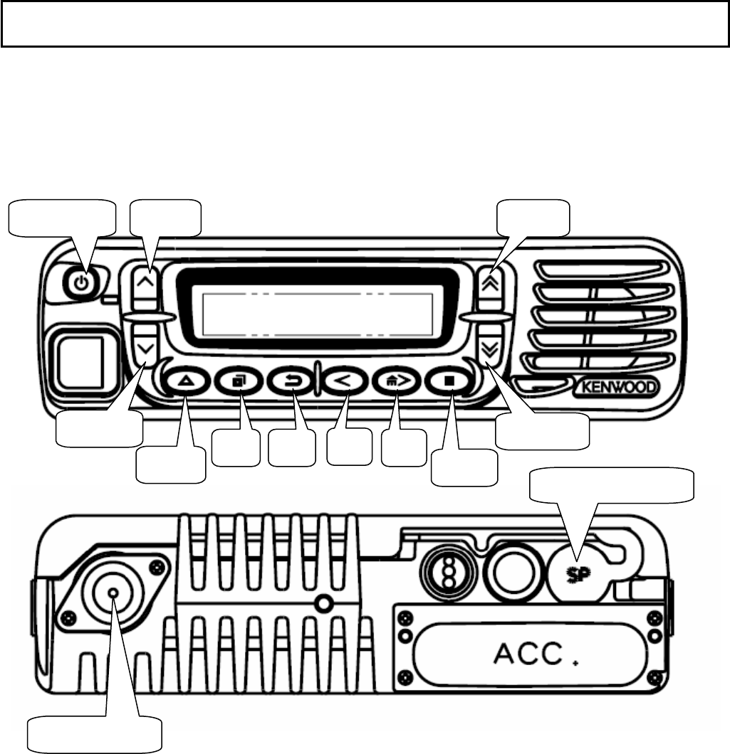
GETTING ACQUAINTED
ORIENTATION
Power-switc Left Up
Left
Right
Right
External speaker jack
Antenna
Triangl
PF1 PF
Squar
PF
PF
NX-700-K FCC ID: K44378600 / IC: 282F-378600
NX-800-K FCC ID: K44378700
Functional and Operational specifications
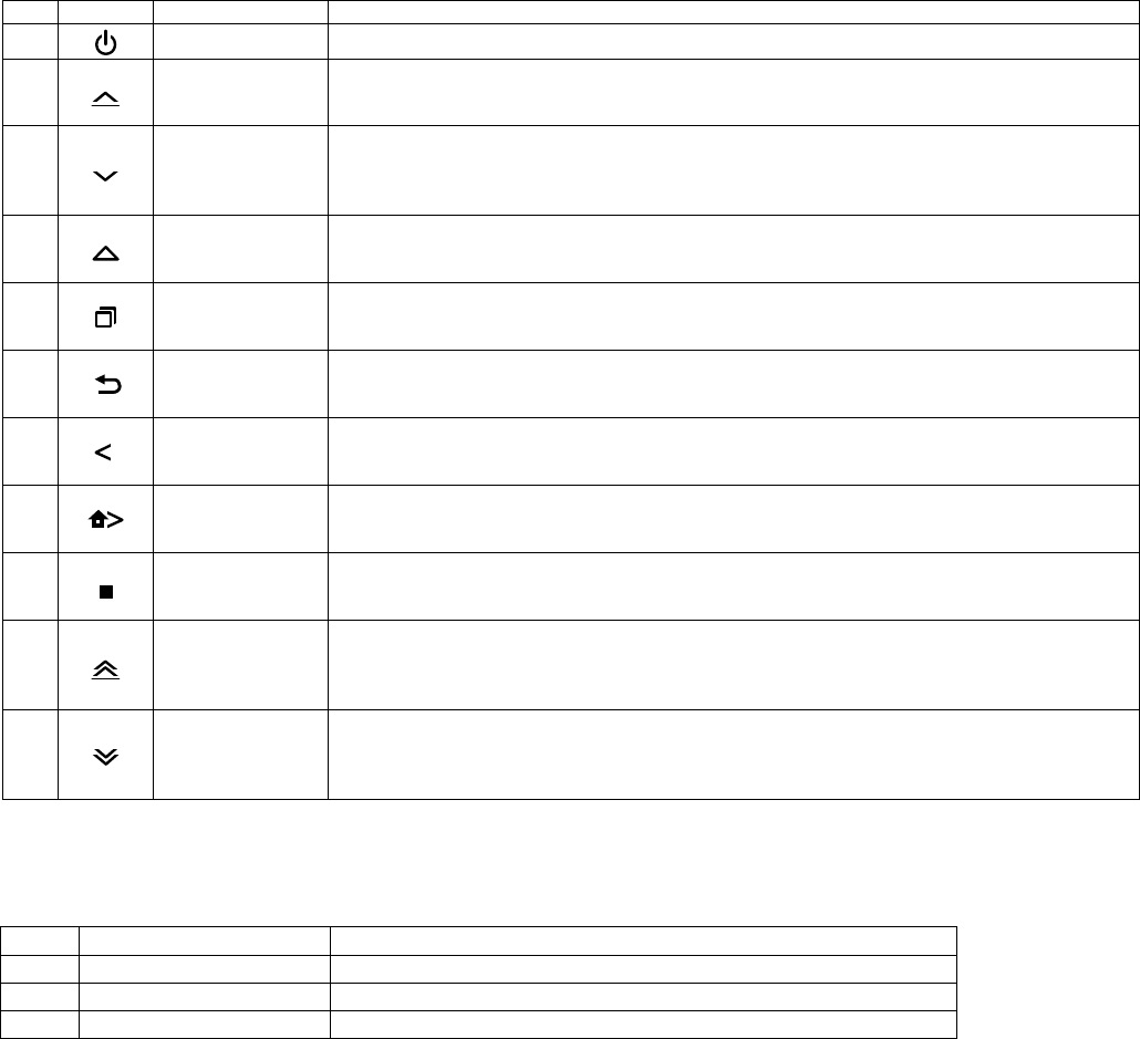
1) Front Panel
Switch(Push type)
No. Print Name Description
1Power-switch Power On/Off
2Left Up
Programmable Function Default : Volume Up
2nd Function Default : None
Hold Default : Volume Up (Continuous)
3Left Down
Programmable Function Default : Volume Down
2nd Function Default : None
Hold Default : Volume Down
(Continuous)
4Triangle
Programmable Function Default : None
2nd Function Default : None
Hold Default : None
5PF1
Programmable Function Default : Menu
2nd Function Default : None
Hold Default : None
6PF2
Programmable Function Default : Squelch Off Momentary
2nd Function Default : None
Hold Default : None
7PF3
Programmable Function Default : Zone Down
2nd Function Default : None
Hold Default : Zone Down (Continuous)
8PF4
Programmable Function Default : Zone Up
2nd Function Default : None
Hold Default : Zone Up (Continuous)
9Square
Programmable Function Default : None
2nd Function Default : None
Hold Default : None
10 Right Up
Programmable Function Default : CH/GID Up
2nd Function Default : None
Hold Default : CH/GID Up
(Continuous)
11 Right Down
Programmable Function Default : CH/GID Down
2nd Function Default : None
Hold Default : CH/GID Down
(Continuous)
Functions of the switches No.2-11 are PC programmable
TX/BUSY INDICATION
No. Name Description
1 Red TX display
2 Green Busy display
3 Orange Call display

NX-700-K FCC ID: K44378600 / IC: 282F-378600
NX-800-K FCC ID: K44378700
OPERATING BASICSATING
ƇSwitching Power ON/OFF
Press the switch to switch the transceiver ON.
Press and hold the switch for approximately 1 second to switch the transceiver OFF.
ƇAdjusting the Volume
The Volume Up/Down SW control to adjust the volume. You can adjust the volume up sw to increases the volume and
the volume down sw to decreases it.
ƇSelecting a Channel
The Channel Up/Down SW to select a channel.
The channel up sw the channel number increases and The channel down sw decreases it.
ƇTransmitting
Note: Before transmitting, first monitor the channel to make sure it is not already in use.
1 Select your desired channel.
• If the channel is busy, wait until it becomes free.
1 Press the microphone PTT switch and speak into the microphone. Release
the PTT switch when you have finished speaking.
• For best sound quality at the receiving station, hold the microphone approximately 1.5 inches (3~4cm) from
your mouth.
ƇReceiving
1 Select your desired channel.
2 When you hear a signal, readjust the volume level if necessary.
2 Respond to the call as described in step 2 of “TRANSMITTING”,above.
AUXILIARY FEATURES
ƇTime-out Timer (TOT)
The purpose of the Time-out Timer is to prevent any caller from using a channel for an extended period of time. If you
continuously transmit for a period of time that exceeds the programmed time, the transceiver will stop transmitting and
an alert tone will sound. To stop the tone, release the PTT switch.
Your dealer can program a warning function to alert you before the TOT expires. Continuously transmitting for the
specified by your dealer will cause the warning tone to sound.
MANDATORY SAFETY INSTRUCTIONS TO INSTALLERS AND USERS
• Use only manufacturer or dealer supplied antennas.
• Antenna Minimum Safe Distance: 120 cm (4 feet), 50% duty Cycle.
• Antenna Gain: 0dBd referenced to a dipole.
The Federal Communications Commission has adopted a safety standard for
human exposure to RF (Radio Frequency) energy which is below the OSHA
(Occupational Safety and Health Act) limits.
• Antenna Mounting: The antenna supplied by the manufacturer or radio dealer
must not be mounted at a location such that during radio transmission, any
person or persons can come closer than the above indicated minimum safe
distance to the antenna, i.e. 120 cm (4 feet) , 50% duty Cycle.
• To comply with current FCC RF Exposure limits, the antenna must be installed
at or exceeding the minimum safe distance shown above, and in accordance
with the requirements of the antenna manufacturer or supplier.
• Vehicle installation: The antenna can be mounted at the center of a vehicle
metal roof or trunk lid, if the minimum safe distance is observed.
• Base Station Installation: The antenna should be À[HGPRXQWHG on an outdoor
permanent structure. RF Exposure compliance must be addressed at the time
of installation.
Antenna substitution: Do not substitute any antenna for the one supplied or
recommended by the manufacturer or radio dealer.
You may be exposing person or persons to excess radio frequency radiation. You
may contact your radio dealer or the manufacturer for further instructions.
Maintain a separation distance from the antenna to person(s) of at least 120 cm (4 feet), 50%
duty Cycle.
“This transmitter is authorized to operate with a maximum duty factor of 50%,
LQW\SLFDOSXVKWRWDONPRGHIRUVDWLVI\LQJ)&&5)H[SRVXUHFRPSOLDQFH
requirements.”
<RXDVWKHTXDOLÀHGHQGXVHURIWKLVUDGLRGHYLFHPXVWFRQWUROWKHH[SRVXUH
conditions of bystanders to ensure the minimum separation distance (above) is
maintained between the antenna and nearby persons for satisfying RF Exposure
compliance. The operation of this transmitter must satisfy the requirements of
2FFXSDWLRQDO&RQWUROOHG([SRVXUH(QYLURQPHQWIRUZRUNUHODWHGXVHWUDQVPLW
only when person(s) are at least the minimum distance from the properly installed,
externally mounted antenna. Transmit only when people outside the vehicle
are at least the recommended minimum lateral distance away from the antenna/
vehicle.
%