JVC KENWOOD 39923220 UHF P25 Transceiver User Manual
JVC KENWOOD Corporation UHF P25 Transceiver
UserManual.wiki
>
JVC KENWOOD
>
39923220 User Manual
Manual
Navigation menu
Upload a User Manual
Namespaces
Wiki Guide
HTML
PDF
Info
Views
User Manual
Discussion / Help
Navigation
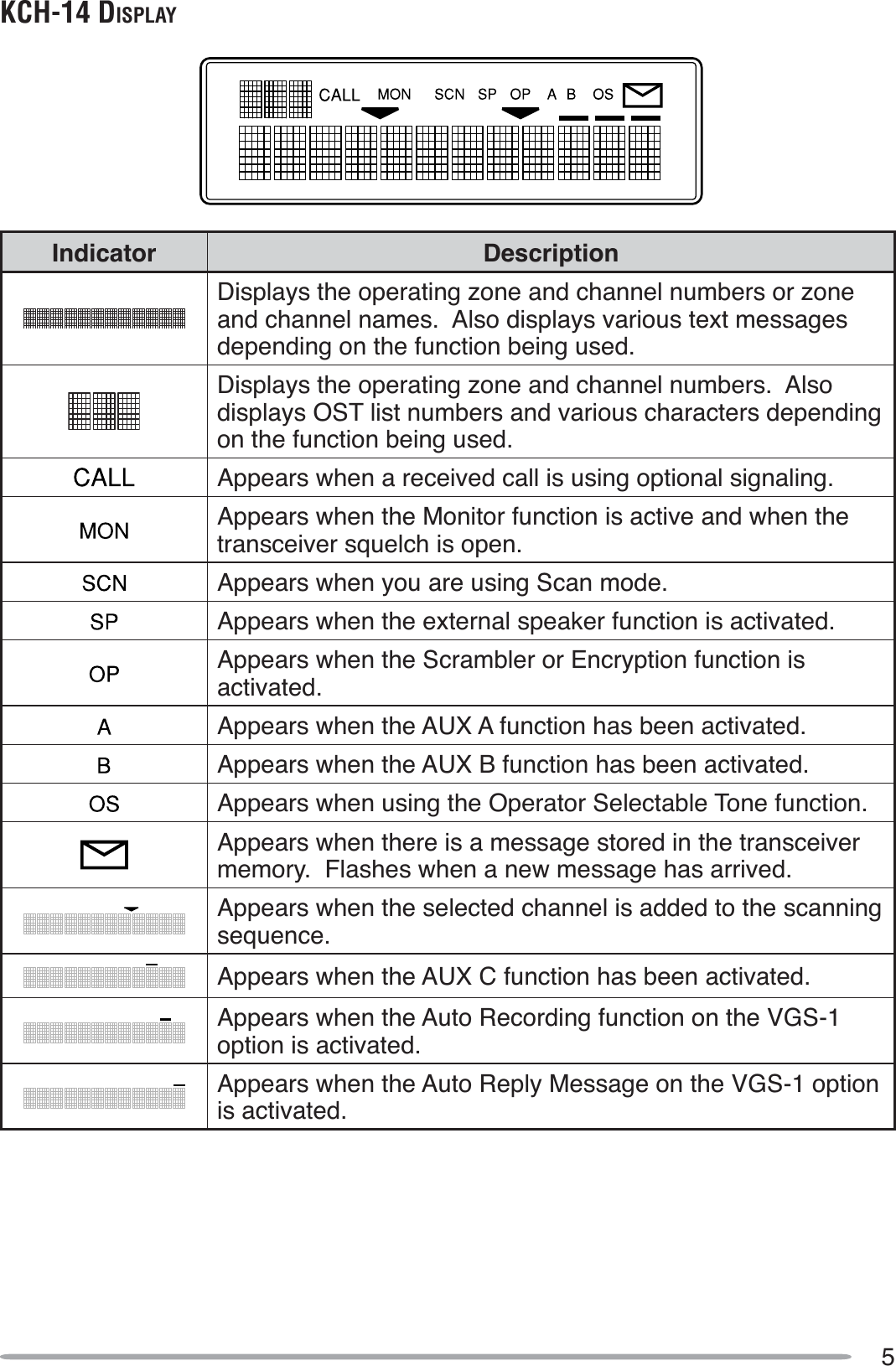
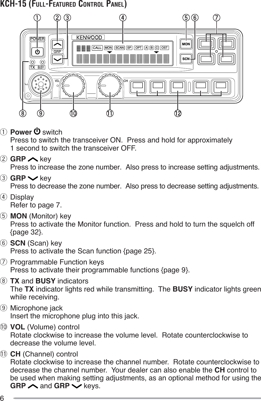
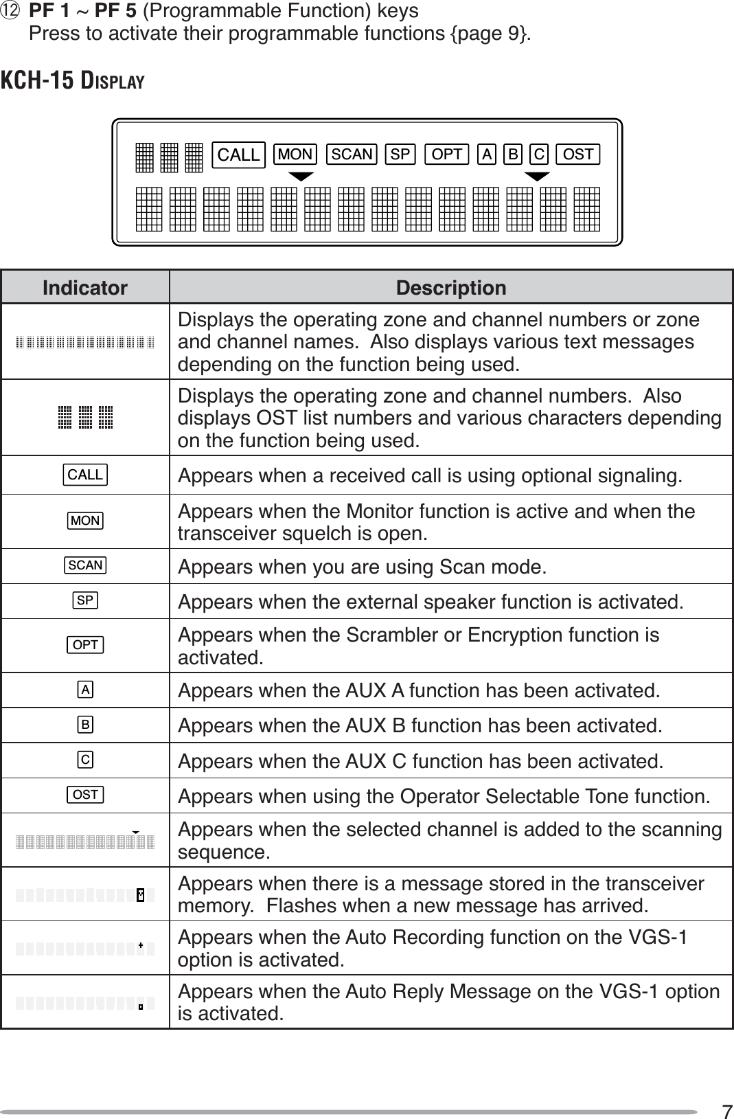
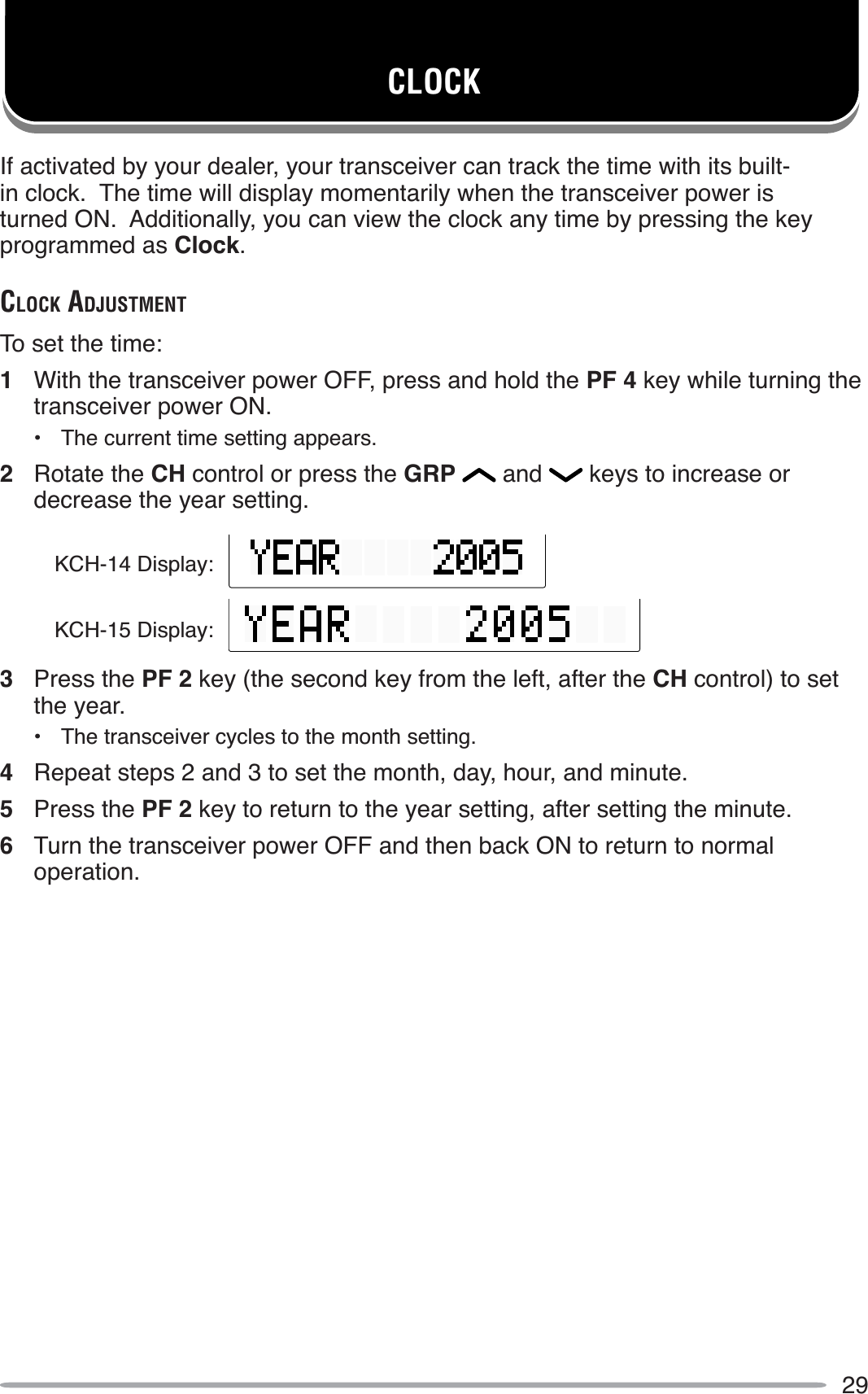
![12SELECTING A ZONE AND CHANNELSelect the desired zone using the GRP and keys. Each zone contains a group of channels.Select the desired channel using the CH control. Each channel is programmed with settings for transmitting and receiving.• If programmed by your dealer, the transceiver will announce the zone and channel numbers as you change them.Names can be programmed for zones and personalities. Your dealer can set the ]RQHQDPHWRDOHQJWKRIWRGLJLWV7RÀWRQWKHGLVSOD\SHUVRQDOLW\QDPHVwill shorten appropriately. (KCH-14 models display only 12 digits). For example, if the channel name is “–CHANNEL1–” and the zone name is “KENWOOD”, and your dealer sets the zone name to 4-digits, the following display will appear:KCH-14 (12-digit display): KENW–CHANNELKCH-15 (14-digit display): KENW–CHANNEL1–TRANSMITTINGFor Trunking channels, refer to “Making Group Calls” and “Making Individual Calls” on the following page.1Select the desired zone and channel using the GRP and keys and the CH control.2Press (or press and hold) the key programmed as Monitor or Squelch Off tocheck whether or not the channel is free.• If the channel is busy, wait until it becomes free.3Press the microphone PTT switch and speak into the microphone. Release the PTT switch to receive.• The TX indicator lights red while transmitting. The BUSY indicator lights green while receiving a signal. This indicator can be disabled by your dealer.• For best sound quality at the receiving station, hold the microphone approximately 1.5 inches (3 ~ 4 cm) from your mouth.](https://usermanual.wiki/JVC-KENWOOD/39923220/User-Guide-788124-Page-17.png)