JVC KENWOOD 407600 VHF FM TRANSCEIVER User Manual Instructional Manual
JVC KENWOOD Corporation VHF FM TRANSCEIVER Instructional Manual
Instructional Manual

TK-7302V/ TK-8302U
TK-7302H/ TK-8302H
TK-7302HV/ TK-8302HU
VHF FM TRANSCEIVER/ UHF FM TRANSCEIVER
INSTRUCTION MANUAL
ÉMETTEUR-RÉCEPTEUR FM VHF/ ÉMETTEUR-RÉCEPTEUR FM UHF
MODE D’EMPLOI
TRANSCEPTOR FM VHF/ TRANSCEPTOR FM UHF
MANUAL DE INSTRUCCIONES
© B62-2167-00 (K,K2)
09 08 07 06 05 04 03 02 01 00
CHVOL

VHF FM TRANSCEIVER/ UHF FM TRANSCEIVER
TK-7302V/ TK-8302U
TK-7302H/ TK-8302H
TK-7302HV/ TK-8302HU
INSTRUCTION MANUAL
ENGLISH

i
One or more of the following statements may be applicable:
FCC WARNING
instruction manual. The user could lose the authority to operate this equipment if an unauthorized
INFORMATION TO THE DIGITAL DEVICE USER REQUIRED BY THE FCC
against harmful interference in a residential installation.
or more of the following measures:
•
•
•
connected.
• Consult the dealer for technical assistance.
Thank You
Kenwood for your personal mobile applications.
noTices To The user
◆
◆
◆
SAFETY:
◆ EXPLOSIVE ATMOSPHERES (GASES, DUST, FUMES, etc.)
◆ INJURY FROM RADIO FREQUENCY TRANSMISSIONS
physical injury.
◆ DYNAMITE BLASTING CAPS
ii
CONTENTS
................................................................................................1
.........................................................................................3
.............................................................................4
...............................................................................................5
........................................................................................................................6
...........................................................................................................7
..............................................................................................................8
.....................................9
....................................................................................10
..............................................................................12
PrecauTions
damage.
appliances.
Kenwood dealer.
Kenwood.
◆
◆ Kenwood
◆
1
GETTING STARTED
Note: The following instructions are for use by your Kenwood dealer, an authorized Kenwood
service facility, or the factory.
Supplied AcceSSorieS
Carefully unpack the transceiver. We recommend that you identify the items
listed below before discarding the packing material. If any items are missing or
have been damaged during shipment, le a claim with the carrier immediately.
DC power cable (with fuses)......................................................1
• 10 A fuse (TK-7302V/ TK-8302U)...............................................2
• 15 A fuse (TK-7302H/ TK-7302HV/ TK-8302H/ TK-8302HU). . . . . . . . . . . . . . . . . . . . . . . . . . 2
Mounting Bracket ..............................................................1
Screw set
• 5 x 16 mm self-tapping screw..................................................4
• Hex-headed screw with washer................................................4
• Spring washer .............................................................4
• Flat washer................................................................4
Microphone (with cable)
• KMC-30 (TK-7302H/ TK-8302H) ...............................................1
• KMC-35 (TK-7302V/ TK-7302HV/ TK-8302U/ TK-8302HU). . . . . . . . . . . . . . . . . . . . . . . . . . . 1
Microphone hanger (with 4 x 16 mm self-tapping screws) . . . . . . . . . . . . . . . . . . . . . . . . . . . . . . . 1
Instruction manual .............................................................1
prepArAtion
Various electronic equipment in your vehicle may malfunction if they are not properly protected
from the radio frequency energy which is present while transmitting. Typical examples include
electronic fuel injection, anti-skid braking, and cruise control. If your vehicle contains such
equipment, consult the dealer for the make of vehicle and enlist his/her aid in determining if they
will perform normally while transmitting.
n Power Cable Connection
The transceiver operates in 12 V negative ground systems only! Check the battery polarity and
voltage of the vehicle before installing the transceiver.
1 Check for an existing hole, conveniently located in the rewall, where the
power cable can be passed through.
• If no hole exists, use a circle cutter to drill a hole, then install a rubber grommet.
2 Run the power cable through the rewall and into the engine compartment.
3 Connect the red lead to the positive (+) battery terminal and the black lead
to the negative (–) battery terminal.
• Place the fuse as close to the battery as possible.
2
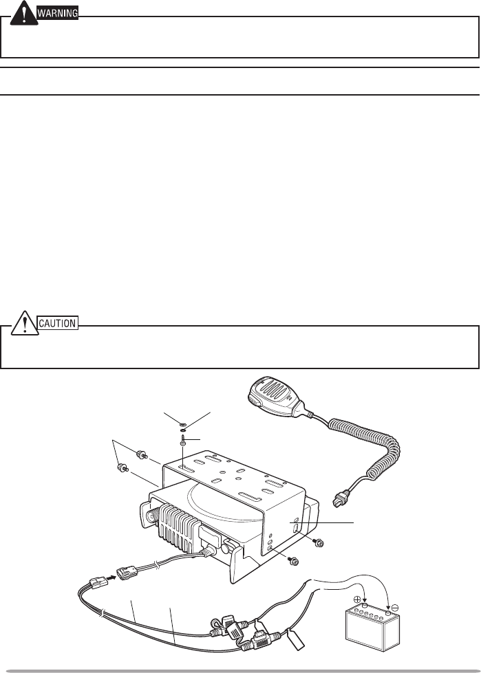
Hex-headed
screw
DC power cable
Mounting bracket
Antenna
connector
Power input
connector
Fuse
Black (–) cable
Red (+) cable
12 V vehicle
battery
Microphone
5 x 16 mm
Self-tapping screw
Spring
washer
Flat
washer
4 Coil the surplus cable and secure it with a retaining band.
• Be sure to leave enough slack in the cables so the transceiver can be removed
for servicing while keeping the power applied.
n Installing the Transceiver
For passenger safety, install the transceiver securely using the supplied mounting bracket and
screw set, so the transceiver will not break loose in the event of a collision.
Note: Before installing the transceiver, check how far the mounting screws will extend below
the surface. When drilling mounting holes, be careful not to damage vehicle wiring or parts.
1 Mark the position of the holes in the dash, using the mounting bracket as a
template. Using a 4.2 mm (5/32 inch) drill bit, drill the holes, then attach the
mounting bracket using the supplied screws.
• Mount the transceiver within easy reach of the user and where there is sufcient
space at the rear of the transceiver for cable connections.
2 Connect the antenna and the supplied power cable to the transceiver.
3 Slide the transceiver into the mounting bracket and secure it using the
supplied hex-headed screws.
4 Mount the microphone hanger in a location where it will be within easy
reach of the user.
• The microphone and microphone cable should be mounted in a place where they
will not interfere with the safe operation of the vehicle.
When replacing the fuse in the DC power cable, be sure to replace it with a fuse of the same
value. Never replace a fuse with one that is rated with a higher value.
3
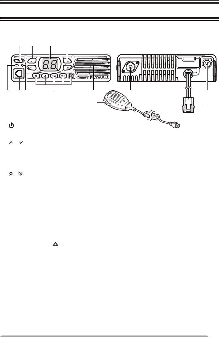
GETTING ACQUAINTED
① (Power) switch
Press to switch the transceiver ON or OFF.
② / keys
Press to activate their programmable functions {page 4}.
③ Display
Refer to page 4.
④ / keys
Press to activate their programmable functions {page 4}.
⑤ TX/RX Indicator
Lights red while transmitting. Lights green while receiving a signal. Flashes
orange when receiving an optional signaling call.
⑥ Microphone jack
Insert the microphone plug into this jack.
⑦ Status Indicator
Lights during a specied mode, based on dealer programming.
⑧ S / A / <B / C> / keys
Press to activate their programmable functions {page 4}.
⑨ Speaker
Internal speaker.
⑩ PTT switch
Press this switch, then speak into the microphone to call a station.
⑪ Antenna connector
Connect the antenna to this connector.
⑫ External speaker jack
Connect an external speaker to this jack.
⑬ Power input connector
Connect the DC Power Cable to this connector.
VOL CH
:@.
=
;
B> 2 8
ACC.
Front/reAr pAnel

4
diSplAy
The display shows the channel number and various modes of operation.
The center and right side dots on the display can be programmed to indicate
specic modes of operation, as listed below.
• AUX
• Channel Delete/Add
• Horn Alert
• Lone Worker
• Operator Selectable Tone
• Priority Channel
• Scrambler
• Talk Around
• Zone Delete/Add
PROGRAMMABLE FUNCTIONS
The , , , , S, A, <B, C>, and keys can be programmed with the functions
listed below. Ask your dealer for details on these functions.
• None
• 2-tone Encode
• AUX
• Autodial
• Channel Down
• Channel Entry
• Channel Up
• Direct Zone Channel 1
• Display Brightness
• Emergency 2
• Horn Alert
• Lone Worker
• Monitor
• Monitor Momentary
• Operator Selectable Tone
• Public Address
• Scan Del/Add
• Scan On/Off
• Scrambler
• Send the GPS Data
• Status 1
• Status 2
• Squelch Level
• Squelch Off
• Squelch Off Momentary
• Talk Around
• Volume Down
• Volume Up
• Zone Down
• Zone Up
1 Direct Zone Channel can be programmed only on the S, A, <B, C>, and keys.
2 Emergency can be programmed only on the key.

5
BASIC OPERATIONS
Switching power on/ oFF
Press to switch the transceiver ON.
• A beep sounds and the display illuminates.
• If the Transceiver Password function is programmed, “PS” will appear on the display
when the power is turned ON. Refer to “Transceiver Password”, below.
Press again to switch the transceiver OFF.
n Transceiver Password
To enter the password:
1 Press / to select a digit.
• When using a keypad, simply enter the password digits and proceed to step 3.
2 Press C> to accept the entered digit and move to the next digit.
• Press A or # to delete an incorrect character. Press and hold A or # to delete all
characters.
• Repeat steps 1 and 2 to enter the entire password.
3 Press S or to conrm the password.
• If you enter an incorrect password, the transceiver remains locked.
AdjuSting the Volume
Press the Volume Up key to increase the volume. Press the Volume Down key
to decrease the volume.
If Squelch Off has been programmed onto a key, you can use that function to
listen to background noise while adjusting the volume level.
Selecting A Zone And chAnnel
Select the desired zone and channel using the keys programmed as Zone Up/
Zone Down and Channel Up/ Channel Down.
• “G1” (Zone 1) appears on the display.
trAnSmitting/ receiVing
1 Select your desired zone and channel.
2 Press microphone PTT switch and speak into the microphone to transmit.
Release the PTT switch to receive.
• For best sound quality at the receiving station, hold the microphone approximately
1.5 inches (3 ~ 4 cm) from your mouth.

6
SCAN
Scan monitors for signals on the transceiver channels. While scanning, the
transceiver checks for a signal on each channel and only stops if a signal is
present.
To start/stop scanning, press the key programmed as Scan On/Off.
• “Sc” appears on the display during Scan.
• When a signal is detected, Scan pauses at that channel. The transceiver will remain on
the busy channel until the signal is no longer present, at which time Scan resumes.
Note: To use Scan, there must be at least 2 channels added to the scanning sequence.
priority ScAn
If a Priority channel has been programmed, the transceiver will automatically
change to the Priority channel when a call is received on that channel, even if call
is being received on a normal channel.
• “P” appears on the display during Priority Scan.
temporAry chAnnel lockout
During scan, you can temporarily remove specic channels from the scanning
sequence by pressing the key programmed as Scan Delete/Add while Scan is
paused at the undesired channel. To temporarily remove a zone, press and hold
Scan Delete/Add while Scan is paused at a channel in the undesired zone.
• The channel/zone is no longer scanned. However, when scanning is ended and
restarted, the Scan settings return to normal.
ScAn delete/Add
You can add and remove zones and/or channels to and from your scan list.
1 Select your desired zone and/or channel.
2 Press the key programmed as Scan Delete/Add to remove a channel or press
and hold the key for approximately 1 second to remove a zone.
ScAn reVert
The Scan Revert channel is the channel selected when you press the PTT switch
to transmit during scan. Your dealer can program one of the following types of
Scan Revert channels:
• Selected: The last channel selected before scan.
• Selected + Talkback: Same as “Selected”, plus you can respond to calls on the
channel at which scan is paused.
• Priority: The Priority channel.
• Priority + Talkback: Same as “Priority”, plus you can respond to calls on the channel
at which scan is paused.
• Last Called + Selected: The last channel on which you receive a call.

7
DTMF CALLS
Note: To make DTMF calls, you must use an optional microphone with a DTMF keypad.
Store & Send
1 Enter up to 16 digits using the keypad.
2 Press the PTT switch to transmit the entered digits.
mAnuAl diAling
1 Press and hold the PTT switch.
2 Enter the desired digits using the keypad.
• If Keypad Auto-PTT is enabled by your dealer, you do not need to press the PTT
switch to transmit; you can make the call simply by pressing the keys.
AutodiAl
Autodial allows you to quickly call DTMF numbers that have been programmed
onto your transceiver.
1 Press the microphone key.
• “Ad” appears on the display.
2 Enter the desired memory location number (1 ~ 9).
3 Press the PTT switch to make the call.
rediAling
1 Press the microphone key.
• “Ad” appears on the display.
2 Press the microphone 0 key.
• If there is no data in the redial memory, an error tone will sound.
3 Press the PTT switch to make the call.
Note: Switching the transceiver power OFF clears the redial memory.
Stun
This function is used when a transceiver is stolen or lost. When the transceiver
receives a call containing a stun code, the transceiver becomes disabled. The
stun code is cancelled when the transceiver receives a call with a revive code.
• “St” appears on the display while the transceiver is stunned.

8
SIGNALING
Quiet tAlk (Qt)/ digitAl Quiet tAlk (dQt)
Your dealer may have programmed QT or DQT signaling on your transceiver
channels. A QT tone/ DQT code is a sub-audible tone/code which allows you to
ignore (not hear) calls from other parties who are using the same channel.
optionAl SignAling
Your dealer may also program several types of optional signaling for your
transceiver channels.
2-tone Signaling: 2-tone Signaling opens the squelch only when your
transceiver receives a call containing matching 2 tones.
DTMF Signaling: DTMF Signaling opens the squelch only when the transceiver
receives a call containing a matching DTMF code.
FleetSync Signaling: Refer to “Selcall (Selective calling)” on page 9.
MDC-1200: MDC-1200 is a data system using Audio
Frequency Shift Keying
(AFSK). Transceivers communicate
at a 1200 baud rate, using 1200 Hz and
1800 Hz tones.
operAtor SelectAble tone (oSt)
You can change the preset encode and decode tones for the selected channel.
Up to 16 OST pairs can be pre-programmed by your dealer.
1 Select your desired channel.
2 Press the key programmed as Operator Selectable Tone.
• “ot” appears on the display, followed by the current OST number.
3 Press <B and C> to select the desired OST number.
4 Use the transceiver the same as in a regular call; press the PTT switch to
transmit and release it to receive.
5 To exit OST mode and return to the preset encode and decode tones, press S.

9
FleetSync: ALPHANUMERIC 2-WAY PAGING FUNCTION
FleetSync is an Alphanumeric 2-way Paging Function and is a protocol owned by
Kenwood Corporation.
Note: If set up by your dealer, your transceiver may use the MDC-1200 feature in place of
FleetSync. MDC-1200 and FleetSync cannot be operated simultaniously.
SelcAll (SelectiVe cAlling)
A Selcall is a voice call to a particular station or to a group of stations.
n Transmitting
1 Select your desired zone and channel.
2 Press the <B and C> keys to select the ID of the station you want to call, or
enter a station ID using a DTMF keypad.
3 Press the microphone PTT switch and begin your conversation.
n Receiving
If enabled by your dealer, an alert tone will sound and the LED will blink when
a Selcall has been received.
To respond to the call, press the PTT switch and speak into the microphone.
n IdenticationCodes
An ID code is a combination of a 3-digit Fleet number and a 4-digit ID number.
Each transceiver must have its own Fleet and ID number.
Note: The ID range may be limited by programming.
pAging cAll
1 Select your desired zone and channel.
2 Press and hold the key programmed as Paging Call for 1 second to transmit
your PTT List ID, to request a call.
StAtuS meSSAge
You can transmit pre-programmed status messages by pressing the keys
programmed as Status 1 and Status 2.
Status messages are 2-digit codes ranging from 10 to 99 (80 ~ 99 are reserved
for special messages), containing messages of up to 16 alphanumeric characters.
gpS report
If a GPS unit (NMEA-0183 format) is installed on your transceiver, you can press
the key programmed as Send the GPS data to send your location data.

10
ADVANCED OPERATIONS
emergency cAllS
If your transceiver has been programmed with the Emergency function, you can
make emergency calls.
1 Press and hold the key programmed as Emergency.
• Depending on the delay time programmed into your transceiver, the length of time
you must hold the Emergency key will vary.
• When the transceiver enters Emergency mode, the transceiver will change to the
Emergency channel and begin transmitting based on how the transceiver is set up.
2 To exit Emergency mode, press and hold the Emergency key again.
• If the Emergency mode completes the preset number of cycles, Emergency mode
will automatically end and the transceiver will return to normal.
n Lone Worker Mode
Lone Worker Mode is a safety feature built into the transceiver. If the
transceiver is not operated for a pre-programmed period of time, the
transceiver will emit a tone and automatically enter Emergency operation.
Press and hold the key programmed as Lone Worker for 2 seconds to toggle
the Lone Worker function ON or OFF.
• “Ln” appears on the display while Lone Worker is activated.
tAlk Around
During interruptions in service (such as a power failure), you can continue to
communicate by using the Talk Around feature. Talk Around allows you to
communicate directly with other transceivers without the use of a repeater, as
long they are not too far away or there are no geographical obstacles in the way.
Press the key programmed as Talk Around to toggle the Talk Around function ON
or OFF.
• “tA” appears on the display while Talk Around is activated.
Voice ScrAmbler
Note: Your dealer can activate the built-in scrambler function, or they can add a more secure
optional scrambler board to your transceiver. Ask your dealer for details.
The built-in scrambler prevent others from easily listening in on your calls. When
activated, the transceiver distorts your voice so that anybody listening to your
conversation will not be able to clearly hear what you are saying.
In order for members of your own group to hear your call while you are using the
scrambler, all members must activate their scrambler functions.
Press the key programmed as Scrambler to toggle the Scrambler function ON or
OFF.
• “Sr” appears on the display while the Scrambler is activated.

11
When using an optional scrambler board, you can change the scrambler code:
1 Press and hold the key programmed as Scrambler for 2 seconds.
• “co” (code) appears on the display, followed by the current scrambler code.
2 Press <B and C> to select your desired scrambler code.
3 Press S or to store the new setting.
• After changing your scrambler code, be sure to inform all of your gorup members of
the new code so they can also reset their transceivers. The scrambler function will
not work with transceivers set up with different scrambler codes.
monitor/ SQuelch oFF
You can use the key programmed as Monitor or Squelch Off to listen to weak
signals that you cannot hear during normal operation and to adjust the volume
when no signals are present on your selected channel.
Your dealer can program a key with one of 4 functions:
• Monitor: Press to deactivate QT, DQT, DTMF, or FleetSync Signaling. Press again to
return to normal operation.
• Monitor Momentary: Press and hold to deactivate QT, DQT, DTMF, or FleetSync
Signaling. Release to return to normal operation.
• Squelch Off: Press to hear background noise. Press again to return to normal
operation.
• Squelch Off Momentary: Press and hold to hear background noise. Release to return
to normal operation.
n Squelch Level
If a key has been programmed as Squelch Level, you can readjust your
transceiver’s squelch level:
1 Press the key programmed as Squelch Level.
• “SL” appears on the display, followed by the current squelch level.
2 Press <B and C> to select the desired squelch level from 0 to 9.
3 Press S or to store the new setting.
public AddreSS (pA)
The PA system can only be used with an optional KAP-2 unit and external speaker.
1 Press the key programmed as Public Address to activate the Public Address
function.
• “PA” appears on the display.
2 Press and hold the PTT switch, then speak into the microphone to make your
address through the external speaker.
3 Press the Public Address key again to exit Public Address.

12
horn Alert
The Horn Alert function can only be used with an optional KAP-2 unit.
Press the key programmed as Horn Alert to toggle the Horn Alert function ON or
OFF.
• “HA” appears on the display while Horn Alert is activated.
BACKGROUND OPERATIONS
time-out timer (tot)
The Time-out Timer is used to prevent you from using a channel for an extended
duration. If you continuously transmit for a preset time, the transceiver will stop
transmitting and an alert tone will sound. Release the PTT switch.
AuxiliAry port
Press the key programmed as AUX to activate the auxiliary port. The auxiliary
port is used with optional boards.
diSplAy brightneSS
You can toggle the display brightness between high and low by pressing the key
programmed as Display Brightness.
direct Zone chAnnel
Press the key programmed as Direct Zone Channel to immediately select the
lowest channel of the lowest zone.
buSy chAnnel lockout (bcl)
If BCL is set up by your dealer, you will be unable to transmit if the channel is
already in use. Use a different channel or wait until the channel becomes free.
ptt id
PTT ID is the transceiver unique ID code which is sent each time the PTT switch
is pressed and/or released.
compAnder
If programmed by your dealer for a channel, the compander will remove
excessive noise from transmitted signals, to provide higher clarity of signals.
Voice Announcement
When changing the channel, an audio voice will announce the new channel.


Terminal Description
ACC (D-SUB 15 Pin Connector)
Pin NO. Pin Name Description Specification I/O Notes
1 SB DC Power Output 13.6 V ± 15 % O
2 IGN Ignition signal Input Power ON: more than 8V
Power OFF: less than 6V I
3 PA Loudspeaker Output 4 Ω O
4 DO Audio Output 500 mV p-p O
5 DI Audio Input 5 k Ω I
6 FNC1 Programmable High Impedance I/O
7 FNC2 Programmable High Impedance I/O
8 FNC3 Programmable High Impedance I/O
9 FNC4 Programmable High Impedance I/O
10 FNC5 Programmable High Impedance I/O
11 FNC6 Programmable High Impedance I/O
12 5C DC Power Output 5 V, Max 100 mA O
13 HR1 Horn Alert Signal Output Max 3A O
14 HR2 Horn Alert Signal Output Max 3A O
15 GND Ground Ground −
Speaker Jack (3.5 mm phone jack) 4W/ 4 Ω
Pin NO. Pin Name Description Specification I/O Notes
1 SPO External Speaker Output 4 Ω O
3 GND Ground Ground −
DC Input Connector
Pin NO. Pin Name Description Specification I/O Notes
Red B DC Power Input 13.6 V ± 15 % I
Black GND Ground Ground I
Microphone Jack
Pin NO. Pin Name Description Specification I/O Notes
1 MBL Backlight of Microphone −O
2 SB DC Power Output 13.6 V ± 15 % O
3 GND Ground Ground −
4 PTT PTT/ PC Serial Data from radio High Impedance I
5 ME MIC Ground Ground −
6 MIC MIC Signal Input 600 Ω I
7 HOOK Hook / PC Serial Data to radio High Impedance I
8 DM MIC Data Detection High Impedance I/O
Antenna Connector
Impedance is 50 Ω.

MANDATORY SAFETY INSTRUCTIONS TO INSTALLERS AND USERS
• Use only manufacturer or dealer supplied antenna.
• Antenna Minimum Safe Distance: 120 cm (4 feet), 50% duty Cycle.
• Antenna Gain: 0 dBd referenced to a dipole.
The Federal Communications Commission has adopted a safety standard for human
exposure to RF (Radio Frequency) energy which is below the OSHA (Occupational Safety
and Health Act) limits.
• Antenna Mounting: The antenna supplied by the manufacturer or radio dealer must not be
mounted at a location such that during radio transmission, any person or persons can
come closer than the above indicated minimum safe distance to the antenna, i.e. 120 cm
(4 feet) , 50% duty Cycle.
• To comply with current FCC RF Exposure limits, the antenna must be installed at or
exceeding the minimum safe distance shown above, and in accordance with the
requirements of the antenna manufacturer or supplier.
• Vehicle installation: The antenna can be mounted at the center of a vehicle metal roof or
trunk lid, if the minimum safe distance is observed.
• Base Station Installation: The antenna should be fixed-mounted on an outdoor permanent
structure. RF Exposure compliance must be addressed at the time of installation.
Antenna substitution: Do not substitute any antenna for the one supplied or recommended
by the manufacturer or radio dealer.
You may be exposing person or persons to excess radio frequency radiation. You may
contact your radio dealer or the manufacturer for further instructions.
Maintain a separation distance from the antenna to person(s) of at least
120 cm (4 feet) , 50% duty Cycle.
“This transmitter is authorized to operate with a maximum duty factor of 50%, in typical
push-to-talk mode, for satisfying FCC RF exposure compliance requirements.”
You, as the qualified end-user of this radio device must control the exposure conditions of
bystanders to ensure the minimum separation distance (above) is maintained between the
antenna and nearby persons for satisfying RF Exposure compliance. The operation of this
transmitter must satisfy the requirements of Occupational/Controlled Exposure
Environment, for work-related use, transmit only when person(s) are at least the minimum
distance from the properly installed, externally mounted antenna. Transmit only when
people outside the vehicle are at least the recommended minimum lateral distance away
from the antenna/vehicle