JVC KENWOOD 415500 UHF FM Mobile Transceiver User Manual
JVC KENWOOD Corporation UHF FM Mobile Transceiver Users Manual
UserManual.wiki
>
JVC KENWOOD
>
415500 User Manual
>
Users Manual
Contents
1.
Users Manual
2.
Users Manual Safety Instructions
Users Manual
Navigation menu
Upload a User Manual
Namespaces
Wiki Guide
HTML
PDF
Info
Views
User Manual
Discussion / Help
Navigation
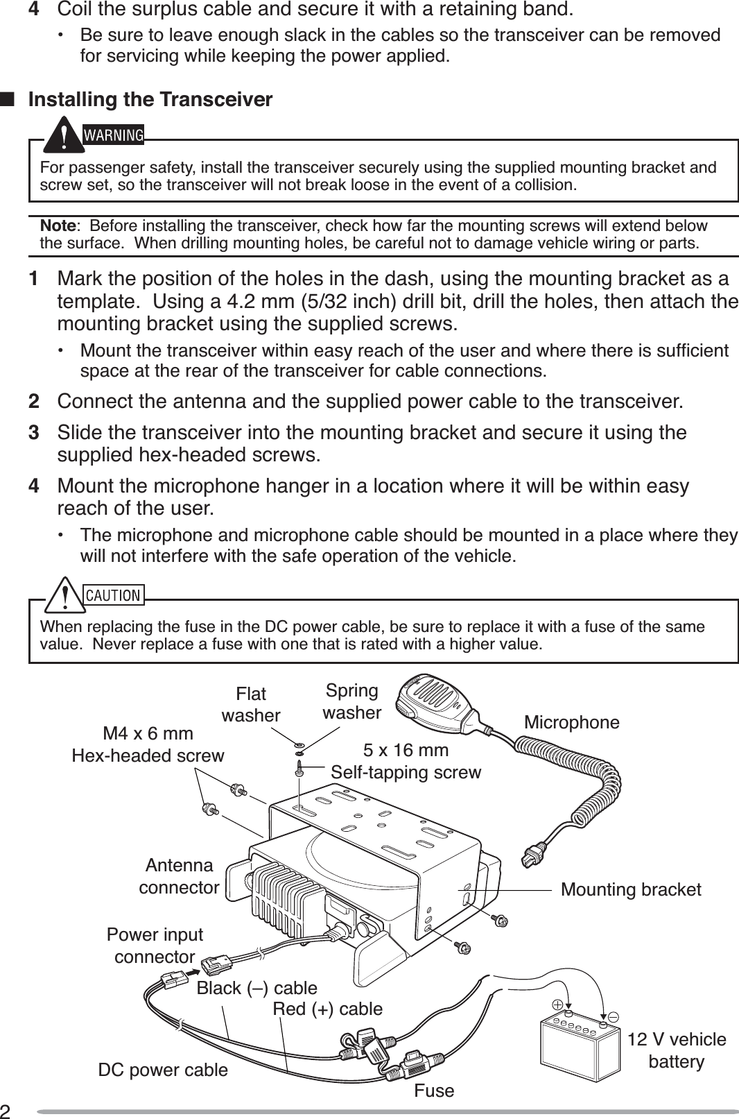
![iOne or more of the following statements may be applicable:FCC WARNING7KLVHTXLSPHQWJHQHUDWHVRUXVHVUDGLRIUHTXHQF\HQHUJ\&KDQJHVRUPRGLÀFDWLRQVWRWKLVHTXLSPHQWPD\FDXVHKDUPIXOLQWHUIHUHQFHXQOHVVWKHPRGLÀFDWLRQVDUHH[SUHVVO\DSSURYHGLQWKHinstruction manual. The user could lose the authority to operate this equipment if an unauthorizedFKDQJHRUPRGLÀFDWLRQLVPDGHINFORMATION TO THE DIGITAL DEVICE USER REQUIRED BY THE FCC7KLVHTXLSPHQWKDVEHHQWHVWHGDQGIRXQGWRFRPSO\ZLWKWKHOLPLWVIRUD&ODVV%GLJLWDOGHYLFHSXUVXDQWWR3DUWRIWKH)&&5XOHV7KHVHOLPLWVDUHGHVLJQHGWRSURYLGHUHDVRQDEOHSURWHFWLRQagainst harmful interference in a residential installation.7KLVHTXLSPHQWJHQHUDWHVXVHVDQGFDQJHQHUDWHUDGLRIUHTXHQF\HQHUJ\DQGLIQRWLQVWDOOHGDQGXVHGLQDFFRUGDQFHZLWKWKHLQVWUXFWLRQVPD\FDXVHKDUPIXOLQWHUIHUHQFHWRUDGLRFRPPXQLFDWLRQV+RZHYHUWKHUHLVQRJXDUDQWHHWKDWWKHLQWHUIHUHQFHZLOOQRWRFFXULQDSDUWLFXODULQVWDOODWLRQ,IWKLVHTXLSPHQWGRHVFDXVHKDUPIXOLQWHUIHUHQFHWRUDGLRRUWHOHYLVLRQUHFHSWLRQZKLFKFDQEHGHWHUPLQHGE\WXUQLQJWKHHTXLSPHQWRIIDQGRQWKHXVHULVHQFRXUDJHGWRWU\WRFRUUHFWWKHLQWHUIHUHQFHE\RQHor more of the following measures: 5HRULHQWRUUHORFDWHWKHUHFHLYLQJDQWHQQD ,QFUHDVHWKHVHSDUDWLRQEHWZHHQWKHHTXLSPHQWDQGUHFHLYHU &RQQHFWWKHHTXLSPHQWWRDQRXWOHWRQDFLUFXLWGLIIHUHQWIURPWKDWWRZKLFKWKHUHFHLYHULVconnected.• Consult the dealer for technical assistance.THANK YOU:HDUHJUDWHIXO\RXKDYHFKRVHQKenwood for your personal mobile applications.7KLVLQVWUXFWLRQPDQXDOFRYHUVRQO\WKHEDVLFRSHUDWLRQVRI\RXUPRELOHUDGLR$VN\RXUGHDOHUIRULQIRUPDWLRQRQDQ\FXVWRPL]HGIHDWXUHVWKH\PD\KDYHDGGHGWR\RXUUDGLRNOTICES TO THE USERX *RYHUQPHQWODZSURKLELWVWKHRSHUDWLRQRIXQOLFHQVHGWUDQVPLWWHUVZLWKLQWKHWHUULWRULHVXQGHUJRYHUQPHQWFRQWUROX ,OOHJDORSHUDWLRQLVSXQLVKDEOHE\ÀQHDQGRULPSULVRQPHQWX 5HIHUVHUYLFHWRTXDOLÀHGWHFKQLFLDQVRQO\SAFETY:,WLVLPSRUWDQWWKDWWKHRSHUDWRULVDZDUHRIDQGXQGHUVWDQGVKD]DUGVFRPPRQWRWKHRSHUDWLRQRIDQ\WUDQVFHLYHUXEXPLOSIVE ATMOSPHERES (GASES, DUST, FUMES, etc.) 7XUQ2))\RXUWUDQVFHLYHUZKLOHWDNLQJRQIXHORUZKLOHSDUNHGLQJDVROLQHVHUYLFHVWDWLRQV'RQRWFDUU\VSDUHIXHOFRQWDLQHUVLQWKHWUXQNRI\RXUYHKLFOHLI\RXUWUDQVFHLYHULVPRXQWHGLQWKHWUXQNDUHDXINJURY FROM RADIO FREQUENCY TRANSMISSIONS 'RQRWRSHUDWH\RXUWUDQVFHLYHUZKHQVRPHERG\LVHLWKHUVWDQGLQJQHDUWRRUWRXFKLQJWKHDQWHQQDWRDYRLGWKHSRVVLELOLW\RIUDGLRIUHTXHQF\EXUQVRUUHODWHGSK\VLFDOLQMXU\XDYNAMITE BLASTING CAPS 2SHUDWLQJWKHWUDQVFHLYHUZLWKLQIHHWPRIG\QDPLWHEODVWLQJFDSVPD\FDXVHWKHPWRH[SORGH7XUQ2))\RXUWUDQVFHLYHUZKHQLQDQDUHDZKHUHEODVWLQJLVLQSURJUHVVRUZKHUH´78512))7:2:$<5$',2µVLJQVKDYHEHHQSRVWHG,I\RXDUHWUDQVSRUWLQJEODVWLQJFDSVLQ\RXUYHKLFOHPDNHVXUHWKH\DUHFDUULHGLQDFORVHGPHWDOER[ZLWKDSDGGHGLQWHULRU'RQRWWUDQVPLWZKLOHWKHFDSVDUHEHLQJSODFHGLQWRRUUHPRYHGIURPWKHFRQWDLQHU](https://usermanual.wiki/JVC-KENWOOD/415500.Users-Manual/User-Guide-1373999-Page-3.png)
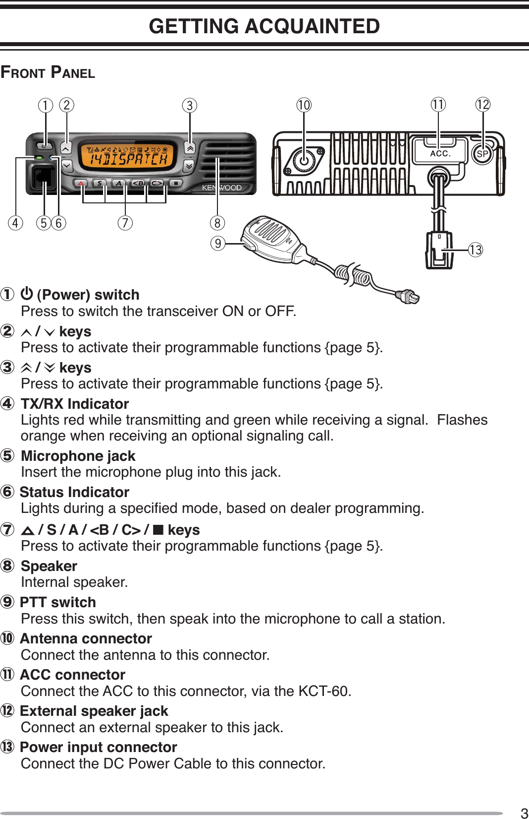
![7TELEPHONE CALLS1Select your desired zone and group ID.• Alternatively, you can press the key programmed as Auto Telephone toautomatically search for a Telephone Repeater.2Press and hold the PTT switch for approximately 1 second to ensure a connection.•&RQÀUPWKDWWKHUHLVDGLDOWRQHDIWHU\RXUHOHDVHWKHPTT switch.3Place the call, following the instructions for making a DTMF call {page 9}.4When the called party responds, press the PTT switch and speak into the microphone. Release the PTT switch to receive.• Only one person can speak at a time (you cannot hear the other person’s voice while you are pressing the PTT switch).5To end the call, press and hold the PTT switch, then press # or the key programmed as Telephone Disconnect.SCANScan monitors for signals on the transceiver channels. While scanning, the transceiver checks for a signal on each channel and only stops if a matching signal is present. There are three types of scans available.•Single Scan: Monitors the channels of only the currently selected zone. If set up to scan the Priority channel, it will be scanned even if it is not in the zone.•Multi Scan: Monitors the channels of every zone.•List Scan:0RQLWRUVWKHFKDQQHOVZLWKLQWKHVSHFLÀHGUDQJHRI]RQHV,IVHWXSWRVFDQthe Priority channel, it will be scanned even if it is not within any of the zones in the list.To start/stop scanning, press the key programmed as Scan.• “SCAN” and the XX icon appear on the display during scan.• When a signal is detected, scan pauses at that channel. The transceiver will remain on the busy channel until the signal is no longer present, at which time scan resumes. Note: To use Scan, there must be at least 2 channels added to the scan sequence.RECALLDuring scan, you can recall the last zone and channel/group ID on which you made a call by pressing the key programmed as CH/GID Recall. Scan will remain paused on the Recall channel until you press the key again.PRIORITY SCANIf a Priority channel has been programmed, the transceiver will automatically change to the Priority channel when a call is received on that channel, even if call is being received on a normal channel.• The XX icon appears on the display when the Priority channel is selected.](https://usermanual.wiki/JVC-KENWOOD/415500.Users-Manual/User-Guide-1373999-Page-11.png)