JVC KENWOOD 415501 UHF FM Mobile Transceiver User Manual
JVC KENWOOD Corporation UHF FM Mobile Transceiver Users Manual
Contents
- 1. Users Manual
- 2. Users Manual Safety Instructions
Users Manual

VHF FM TRANSCEIVER/
UHF FM TRANSCEIVER
TK-7360/ TK-8360
TK-7360H/ TK-8360H
TK-7360HV/ TK-8360HU
INSTRUCTION MANUAL
ENGLISH
Firmware Copyrights
The title to and ownership of copyrights for rmware
embedded in Kenwood product memories are reserved for
Kenwood Corporation.

Terminal Descriptions
ACC (D-SUB 15 Pin Connector)
No. Name I/O Description 6SHFLÀFDWLRQ
1 SB O DC Power Output 13.6 V ±15%
2 IGN I Igintion Signal Input Power On: Over 8 V
Power Off: Under 6 V
3 PA O Loudspeaker Output ї
4 DO O Audio Output 500 mVp-p
5 DI I Audio Input Nї
6 FNC1 I/O Programmable High Impedance
7 FNC2 I/O Programmable High Impedance
8 FNC3 I/O Programmable High Impedance
9 FNC4 I/O Programmable High Impedance
10 FNC5 I/O Programmable High Impedance
11 FNC6 I/O Programmable High Impedance
12 5C O DC Power Output 5 V, Max 100 mA
13 HR1 O Horn Alert Signal Output Max 3 A
14 HR2 O Horn Alert Signal Output Max 3 A
15 GND — Ground Ground
6SHDNHU-DFNPP3KRQH-DFN:ї
No. Name I/O Description 6SHFLÀFDWLRQ
1 SPO O External Speaker Output ї
3 GND — Ground Ground
DC Input Connector
No. Name I/O Description 6SHFLÀFDWLRQ
Red B I DC Power Input 13.6 V ±15%
Black GND I Ground Ground
Microphone Jack
No. Name I/O Description 6SHFLÀFDWLRQ
1 MBL O Backlight of Microphone —
2 SB O DC Power Output 13.6 V ±15%
3 GND — Ground Ground
4 PTT I/O PTT/ PC Serial Data from Radio High Impedance
5 ME — Mic Ground Ground
6 MIC I Mic Signal Input ї
7 HOOK I Hook/ PC Serial Data to Radio High Impedance
8 DM I/O Mic Data Detection High Impedance
Antenna Terminal
їLPSHGDQFH

i
One or more of the following statements may be applicable:
FCC WARNING
7KLVHTXLSPHQWJHQHUDWHVRUXVHVUDGLRIUHTXHQF\HQHUJ\&KDQJHVRUPRGLÀFDWLRQVWRWKLV
HTXLSPHQWPD\FDXVHKDUPIXOLQWHUIHUHQFHXQOHVVWKHPRGLÀFDWLRQVDUHH[SUHVVO\DSSURYHGLQWKH
instruction manual. The user could lose the authority to operate this equipment if an unauthorized
FKDQJHRUPRGLÀFDWLRQLVPDGH
INFORMATION TO THE DIGITAL DEVICE USER REQUIRED BY THE FCC
7KLVHTXLSPHQWKDVEHHQWHVWHGDQGIRXQGWRFRPSO\ZLWKWKHOLPLWVIRUD&ODVV%GLJLWDOGHYLFH
SXUVXDQWWR3DUWRIWKH)&&5XOHV7KHVHOLPLWVDUHGHVLJQHGWRSURYLGHUHDVRQDEOHSURWHFWLRQ
against harmful interference in a residential installation.
7KLVHTXLSPHQWJHQHUDWHVXVHVDQGFDQJHQHUDWHUDGLRIUHTXHQF\HQHUJ\DQGLIQRWLQVWDOOHGDQG
XVHGLQDFFRUGDQFHZLWKWKHLQVWUXFWLRQVPD\FDXVHKDUPIXOLQWHUIHUHQFHWRUDGLRFRPPXQLFDWLRQV
+RZHYHUWKHUHLVQRJXDUDQWHHWKDWWKHLQWHUIHUHQFHZLOOQRWRFFXULQDSDUWLFXODULQVWDOODWLRQ,IWKLV
HTXLSPHQWGRHVFDXVHKDUPIXOLQWHUIHUHQFHWRUDGLRRUWHOHYLVLRQUHFHSWLRQZKLFKFDQEHGHWHUPLQHG
E\WXUQLQJWKHHTXLSPHQWRIIDQGRQWKHXVHULVHQFRXUDJHGWRWU\WRFRUUHFWWKHLQWHUIHUHQFHE\RQH
or more of the following measures:
5HRULHQWRUUHORFDWHWKHUHFHLYLQJDQWHQQD
,QFUHDVHWKHVHSDUDWLRQEHWZHHQWKHHTXLSPHQWDQGUHFHLYHU
&RQQHFWWKHHTXLSPHQWWRDQRXWOHWRQDFLUFXLWGLIIHUHQWIURPWKDWWRZKLFKWKHUHFHLYHULV
connected.
• Consult the dealer for technical assistance.
THANK YOU
:HDUHJUDWHIXO\RXKDYHFKRVHQKenwood for your personal mobile applications.
7KLVLQVWUXFWLRQPDQXDOFRYHUVRQO\WKHEDVLFRSHUDWLRQVRI\RXUPRELOHUDGLR$VN\RXUGHDOHUIRU
LQIRUPDWLRQRQDQ\FXVWRPL]HGIHDWXUHVWKH\PD\KDYHDGGHGWR\RXUUDGLR
NOTICES TO THE USER
X *RYHUQPHQWODZSURKLELWVWKHRSHUDWLRQRIXQOLFHQVHGWUDQVPLWWHUVZLWKLQWKHWHUULWRULHVXQGHU
JRYHUQPHQWFRQWURO
X ,OOHJDORSHUDWLRQLVSXQLVKDEOHE\ÀQHDQGRULPSULVRQPHQW
X 5HIHUVHUYLFHWRTXDOLÀHGWHFKQLFLDQVRQO\
SAFETY:,WLVLPSRUWDQWWKDWWKHRSHUDWRULVDZDUHRIDQGXQGHUVWDQGVKD]DUGV
FRPPRQWRWKHRSHUDWLRQRIDQ\WUDQVFHLYHU
XEXPLOSIVE ATMOSPHERES (GASES, DUST, FUMES, etc.)
7XUQ2))\RXUWUDQVFHLYHUZKLOHWDNLQJRQIXHORUZKLOHSDUNHGLQJDVROLQHVHUYLFHVWDWLRQV'R
QRWFDUU\VSDUHIXHOFRQWDLQHUVLQWKHWUXQNRI\RXUYHKLFOHLI\RXUWUDQVFHLYHULVPRXQWHGLQWKH
WUXQNDUHD
XINJURY FROM RADIO FREQUENCY TRANSMISSIONS
'RQRWRSHUDWH\RXUWUDQVFHLYHUZKHQVRPHERG\LVHLWKHUVWDQGLQJQHDUWRRUWRXFKLQJWKH
DQWHQQDWRDYRLGWKHSRVVLELOLW\RIUDGLRIUHTXHQF\EXUQVRUUHODWHGSK\VLFDOLQMXU\
XDYNAMITE BLASTING CAPS
2SHUDWLQJWKHWUDQVFHLYHUZLWKLQIHHWPRIG\QDPLWHEODVWLQJFDSVPD\FDXVHWKHP
WRH[SORGH7XUQ2))\RXUWUDQVFHLYHUZKHQLQDQDUHDZKHUHEODVWLQJLVLQSURJUHVVRUZKHUH
´78512))7:2:$<5$',2µVLJQVKDYHEHHQSRVWHG,I\RXDUHWUDQVSRUWLQJEODVWLQJFDSV
LQ\RXUYHKLFOHPDNHVXUHWKH\DUHFDUULHGLQDFORVHGPHWDOER[ZLWKDSDGGHGLQWHULRU'RQRW
WUDQVPLWZKLOHWKHFDSVDUHEHLQJSODFHGLQWRRUUHPRYHGIURPWKHFRQWDLQHU
ii
CONTENTS
*(77,1*67$57(' ................................................................................................1
*(77,1*$&48$,17(' .........................................................................................3
352*5$00$%/()81&7,216 .............................................................................5
%$6,&23(5$7,216...............................................................................................5
6&$1........................................................................................................................7
'70)&$//6 ...........................................................................................................8
6,*1$/,1* ............................................................................................................
)OHHW6\QF$/3+$180(5,&:$<3$*,1*)81&7,21 ................................... 11
$'9$1&('23(5$7,216....................................................................................13
%$&.*5281'23(5$7,216..............................................................................16
9*6237,21$/92,&(*8,'(6725$*(81,7 ..........................................17
PRECAUTIONS
2EVHUYHWKHIROORZLQJSUHFDXWLRQVWRSUHYHQWÀUHSHUVRQDOLQMXU\DQGWUDQVFHLYHU
damage.
'RQRWDWWHPSWWRFRQÀJXUHWKHWUDQVFHLYHUZKLOHGULYLQJLWLVWRRGDQJHURXV
'RQRWGLVDVVHPEOHRUPRGLI\WKHWUDQVFHLYHUIRUDQ\UHDVRQ
'RQRWH[SRVHWKHWUDQVFHLYHUWRORQJSHULRGVRIGLUHFWVXQOLJKWQRUSODFHLWQHDUKHDWLQJ
appliances.
,IDQDEQRUPDORGRURUVPRNHLVGHWHFWHGFRPLQJIURPWKHWUDQVFHLYHUVZLWFKWKH
WUDQVFHLYHUSRZHURIILPPHGLDWHO\DQGFRQWDFW\RXUKenwood dealer.
8VHRIWKHWUDQVFHLYHUZKLOH\RXDUHGULYLQJPD\EHDJDLQVWWUDIÀFODZV3OHDVHFKHFN
DQGREVHUYHWKHYHKLFOHUHJXODWLRQVLQ\RXUDUHD
'RQRWXVHRSWLRQVQRWVSHFLÀHGE\Kenwood.
X 7KHWUDQVFHLYHURSHUDWHVLQ9QHJDWLYHJURXQGV\VWHPVRQO\&KHFNWKHEDWWHU\SRODULW\DQG
YROWDJHRIWKHYHKLFOHEHIRUHLQVWDOOLQJWKHWUDQVFHLYHU
X 8VHRQO\WKHVXSSOLHG'&SRZHUFDEOHRUDKenwood RSWLRQDO'&SRZHUFDEOH
X 'RQRWFXWDQGRUUHPRYHWKHIXVHKROGHURQWKH'&SRZHUFDEOH
)RUSDVVHQJHUVDIHW\LQVWDOOWKHWUDQVFHLYHUVHFXUHO\XVLQJWKHVXSSOLHGPRXQWLQJEUDFNHWDQG
VFUHZVHWVRWKHWUDQVFHLYHUZLOOQRWEUHDNORRVHLQWKHHYHQWRIDFROOLVLRQ

1
GETTING STARTED
Note: The following instructions are for use by your Kenwood dealer, an authorized Kenwood
service facility, or the factory.
SUPPLIED ACCESSORIES
Carefully unpack the transceiver. We recommend that you identify the items
listed below before discarding the packing material. If any items are missing or
KDYHEHHQGDPDJHGGXULQJVKLSPHQWÀOHDFODLPZLWKWKHFDUULHULPPHGLDWHO\
DC power cable (with fuses)......................................................1
• 10 A fuse..................................................................2
Mounting Bracket ..............................................................1
Screw set
• 5 x 16 mm self-tapping screw..................................................4
• Hex-headed screw with washer ................................................4
• Spring washer .............................................................4
• Flat washer................................................................4
Microphone (with cable)
• KMC-30 ..................................................................1
Microphone hanger (with 4 x 16 mm self-tapping screws) ...............................1
Instruction manual .............................................................1
PREPARATION
Various electronic equipment in your vehicle may malfunction if they are not properly protected
from the radio frequency energy which is present while transmitting. Typical examples include
electronic fuel injection, anti-skid braking, and cruise control. If your vehicle contains such
equipment, consult the dealer for the make of vehicle and enlist his/her aid in determining if they
will perform normally while transmitting.
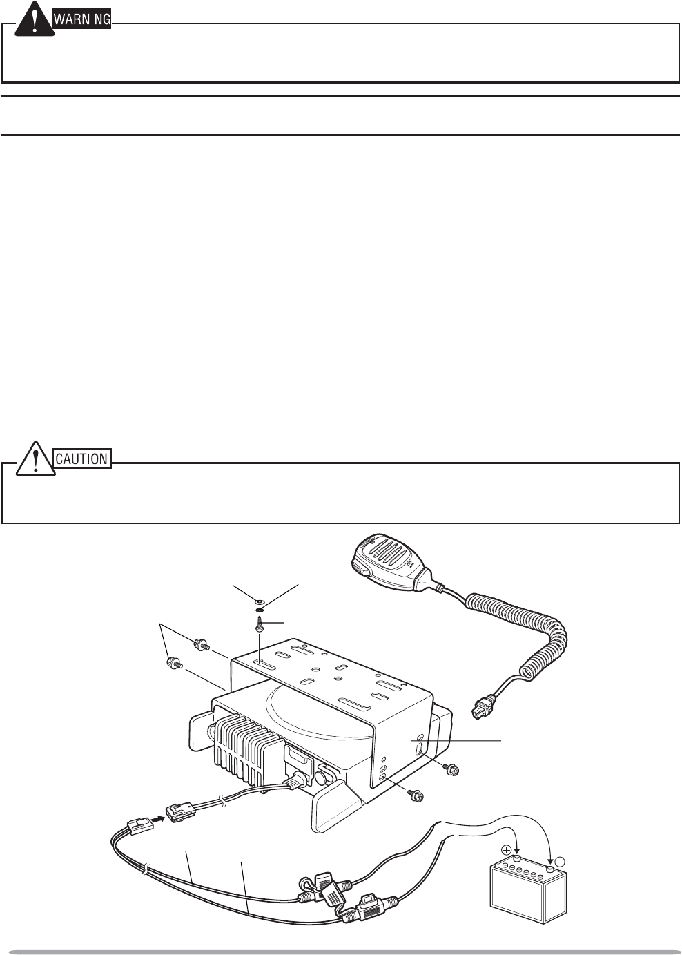
QPower Cable Connection
The transceiver operates in 12 V negative ground systems only! Check the battery polarity and
voltage of the vehicle before installing the transceiver.
1 &KHFNIRUDQH[LVWLQJKROHFRQYHQLHQWO\ORFDWHGLQWKHÀUHZDOOZKHUHWKH
power cable can be passed through.
• If no hole exists, use a circle cutter to drill a hole, then install a rubber grommet.
2 5XQWKHSRZHUFDEOHWKURXJKWKHÀUHZDOODQGLQWRWKHHQJLQHFRPSDUWPHQW
3Connect the red lead to the positive (+) battery terminal and the black lead
to the negative (–) battery terminal.
• Place the fuse as close to the battery as possible.
2
M4 x 6 mm
Hex-headed screw
DC power cable
Mounting bracket
Antenna
connector
Power input
connector
Fuse
Black (–) cable
Red (+) cable
12 V vehicle
battery
Microphone
5 x 16 mm
Self-tapping screw
Spring
washer
Flat
washer
4Coil the surplus cable and secure it with a retaining band.
• Be sure to leave enough slack in the cables so the transceiver can be removed
for servicing while keeping the power applied.
QInstalling the Transceiver
For passenger safety, install the transceiver securely using the supplied mounting bracket and
screw set, so the transceiver will not break loose in the event of a collision.
Note: Before installing the transceiver, check how far the mounting screws will extend below
the surface. When drilling mounting holes, be careful not to damage vehicle wiring or parts.
1Mark the position of the holes in the dash, using the mounting bracket as a
template. Using a 4.2 mm (5/32 inch) drill bit, drill the holes, then attach the
mounting bracket using the supplied screws.
0RXQWWKHWUDQVFHLYHUZLWKLQHDV\UHDFKRIWKHXVHUDQGZKHUHWKHUHLVVXIÀFLHQW
space at the rear of the transceiver for cable connections.
2Connect the antenna and the supplied power cable to the transceiver.
3Slide the transceiver into the mounting bracket and secure it using the
supplied hex-headed screws.
4Mount the microphone hanger in a location where it will be within easy
reach of the user.
• The microphone and microphone cable should be mounted in a place where they
will not interfere with the safe operation of the vehicle.
When replacing the fuse in the DC power cable, be sure to replace it with a fuse of the same
value. Never replace a fuse with one that is rated with a higher value.
3
GETTING AC
Q
UAINTED
F
R
O
N
T
P
A
NEL
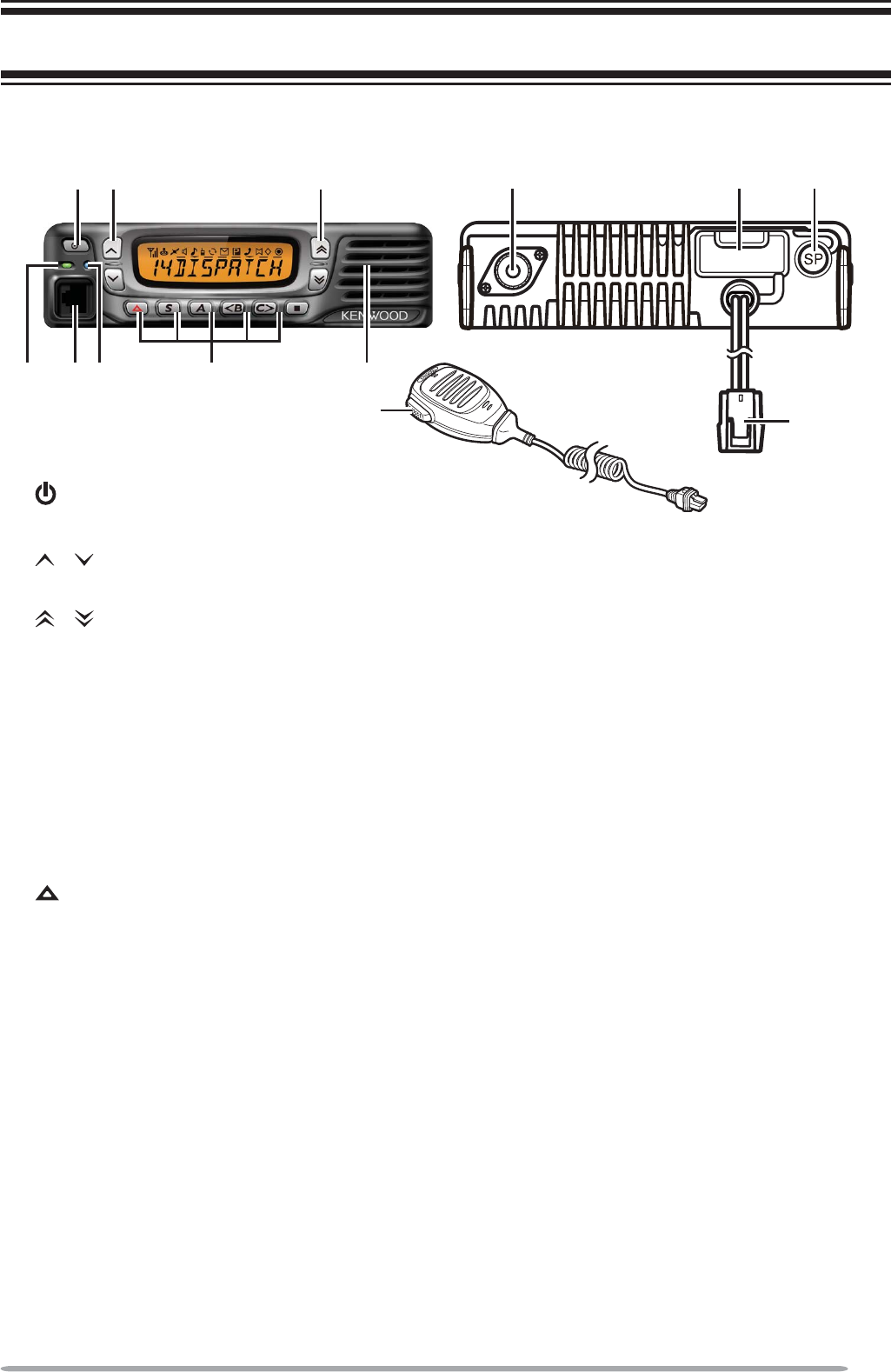
①
(
Power
)
switch
P
ress to switch the transceiver ON or OFF.
②
/
k
e
ys
P
ress to activate their pro
g
rammable functions
{
pa
g
e 5
}
.
③/ keys
P
ress to activate their programmable functions
{
page 5
}
.
④
TX
/
RX Indi
c
at
o
r
L
ig
h
ts re
d
w
h
ile transmitting an
d
green w
h
ile receiving a signal. Flas
h
es
oran
g
e w
h
en receivin
g
an optional si
g
nalin
g
call.
⑤Microphone jack
Insert the microphone plug into this jack.
⑥
S
tatu
s
Indi
c
at
o
r
/
LJKWVGXULQJDVSHFL
À
HGPRGHEDVHGRQGHDOHUSURJUDPPLQJ
⑦ / S / A / <B /
C
> /
Q
k
eys
P
ress to activate their programmable functions
{
page 5
}
.
⑧
Sp
eaker
I
nterna
l
spea
k
er.
⑨
P
TT switc
h
P
ress t
h
is switc
h
, t
h
en speak into t
h
e microp
h
one to call a station
.
⑩
A
ntenna connecto
r
Connect the antenna to thi
s
connector.
⑪
ACC
connector
C
onnect the A
CC
to this connector, via the K
C
T-60
.
⑫External speaker jack
Connect an external speaker to this
j
ack
.
⑬
P
ower
i
n
p
ut connector
C
onnect the D
C
Power
C
able to this connector.
;=B > 2
8
ACC.
:@.
4
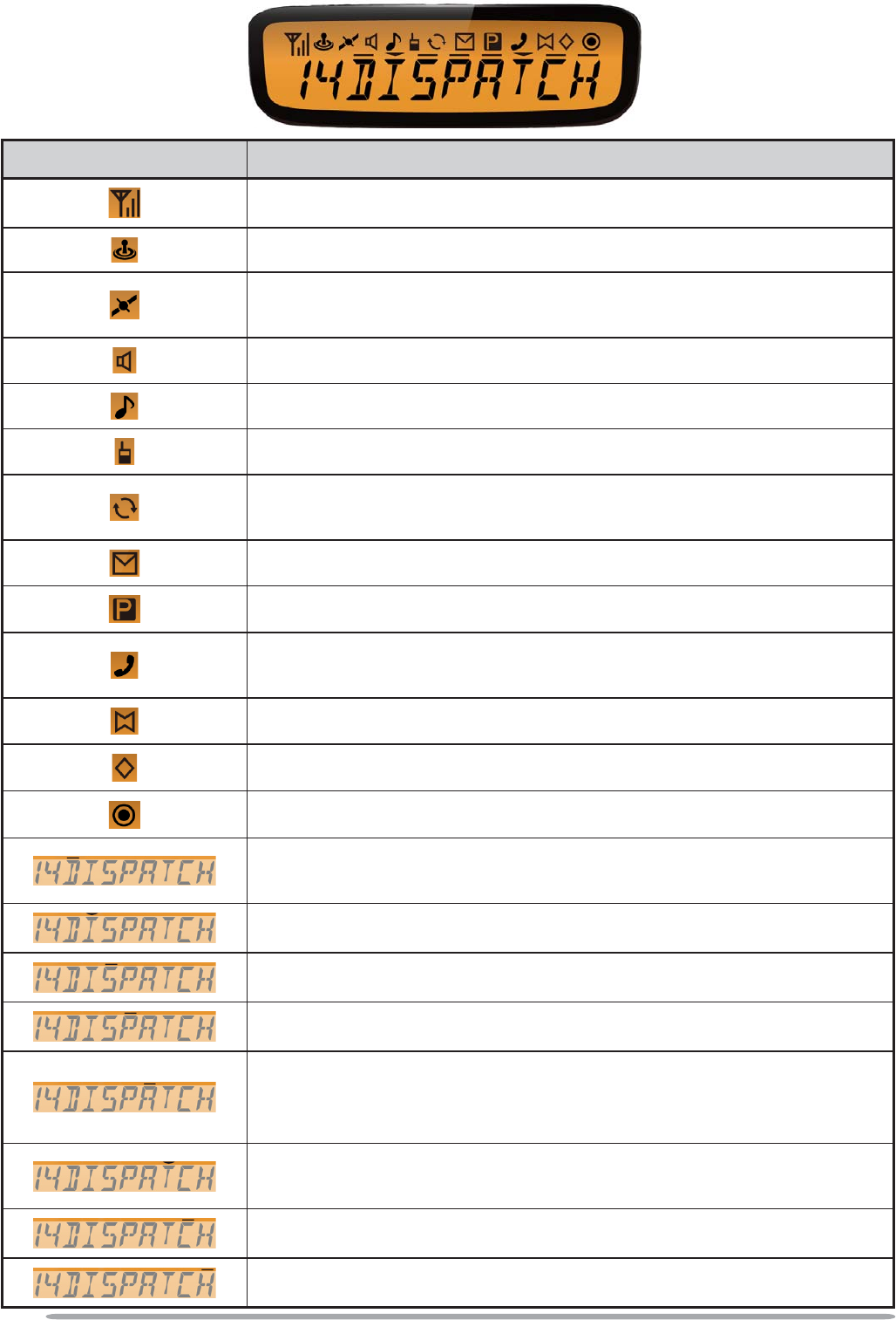
DISPLAY
Icon Description
Displays the signal strength (RSSI).
Not used.
Lights when the GPS position is determined. Blinks
when the GPS position is not determined.
Signaling is turned off.
An LTR call is being received.
The Talk Around function is on.
Lights while scanning or while paused on a channel.
Blinks when scan is temporarily stopped.
A message is in the stack memory.
The selected channel is the Priority channel.
Lights when receiving a Telephone ID call. Blinks when
using Auto Telephone Search.
The Horn Alert function is on.
The Scrambler function is on.
The Public Address function is on.
The selected channel is the Channel/Group ID Recall
channel.
The current zone is added to the scan sequence.
The External Speaker function is on.
The AUX function is on.
Lights when the Auto Recording function is on. Blinks
when the Auto Recording data is being written to the
ÁDVKPHPRU\
The current Channel/Group ID is added to the scan
sequence.
The Operator Selectable Tone function is on.
The Auto Reply Message function is on.

5
PROGRAMMABLE FUNCTIONS
The , , , , , S,A,<B,C>, and Q keys can be programmed with the
functions listed below. Ask your dealer for details on these functions.
• None
• 2-tone
• Auto Telephone
• Auto Reply Message
• Autodial
• Autodial Programming
• AUX
• Call 1 ~ 3
• Calling Alert
• CH/GID Down
• CH/GID Recall
• CH/GID Up
• Channel Entry
• Direct CH/GID 1 ~ 4
• Display Character
• Emergency 1
• External Speaker
• Function
• GPS Position Display
• Home CH/GID
• Horn Alert
• Key Lock
• LCD Brightness
• Lone Worker
• Monitor
• Monitor Momentary
• OST
• Paging Call
• Playback
• Public Address
• RSSI Indicator
• Scan
• Scan Del/Add
• Scrambler
• Selcall
• Selcall + Status
• Send the GPS Data
• Squelch Level
• Squelch Off
• Squelch Off Momentary
• Status
• Status 1 ~ Status 3
• Talk Around
• Telephone Disconnect
• Transceiver Password
• Volume Down
• Volume Up
• Zone Down
• Zone Up
1Emergency can be programmed only on the key.
BASIC OPERATIONS
SWITCHING POWER ON/ OFF
Press to switch the transceiver ON.
• A beep sounds and the display illuminates.
• If the Transceiver Password function is programmed, “PASSWORD” will appear on the
display. Refer to “Transceiver Password”, on page 6.
Press again to switch the transceiver OFF.

6
QTransceiver Password
To enter the password:
1Press / to select a digit.
• When using a keypad, simply enter the password digits and proceed to step 3.
2Press C> to accept the entered digit and move to the next digit.
• Press A or # to delete an incorrect digit. Press and hold A or #to delete all
digits.
3Repeat steps 1 and 2 to enter the entire password.
4Press S or WRFRQÀUPWKHSDVVZRUG
• If you enter an incorrect password, the transceiver remains locked.
ADJUSTING THE VOLUME
Press the Volume Up key to increase the volume. Press the Volume Down key
to decrease the volume.
If Squelch Off has been programmed onto a key, you can use that function to
listen to background noise while adjusting the volume level.
SELECTING A ZONE AND CHANNEL/GROUP ID
Select the desired zone and channel/group ID using the keys programmed as
Zone Up/Zone Down and CH/GID Up/CH/GID Down.
• You can program names for zones and channels/group IDs with up to 10
characters.
QHome Channel/Group ID
You can select your Home channel and group ID by pressing Home CH/GID.
Press the key a second time to return to your previous channel/group ID.
QDirect Channel/Group ID
You can quickly select a commonly used channel and group ID by pressing
Direct CH/GID 1 ~ Direct CH/GID 4. Press the same key a second time to
return to your previous channel/group ID.
TRANSMITTING/RECEIVING
1Select your desired zone and channel.
2Press the Calling Alert key to notify others that you are starting a call.
• Simply release the Calling Alert key to stop the tone.
3Press the microphone PTT switch and speak into the microphone to transmit.
Release the PTT switch to receive.
• For best sound quality at the receiving station, hold the microphone approximately
1.5 inches (3 ~ 4 cm) from your mouth.

7
TELEPHONE CALLS
1Select your desired zone and group ID.
• Alternatively, you can press the key programmed as Auto Telephone to
automatically search for a Telephone Repeater.
2Press and hold the PTT switch for approximately 1 second to ensure a
connection.
•&RQÀUPWKDWWKHUHLVDGLDOWRQHDIWHU\RXUHOHDVHWKHPTT switch.
3Place the call, following the instructions for making a DTMF call {page 9}.
4When the called party responds, press the PTT switch and speak into the
microphone. Release the PTT switch to receive.
• Only one person can speak at a time (you cannot hear the other person’s voice
while you are pressing the PTT switch).
5To end the call, press and hold the PTT switch, then press # or the key
programmed as Telephone Disconnect.
SCAN
Scan monitors for signals on the transceiver channels. While scanning, the
transceiver checks for a signal on each channel and only stops if a matching
signal is present. There are three types of scans available.
•Single Scan: Monitors the channels of only the currently selected zone. If set up to
scan the Priority channel, it will be scanned even if it is not in the zone.
•Multi Scan: Monitors the channels of every zone.
•List Scan:0RQLWRUVWKHFKDQQHOVZLWKLQWKHVSHFLÀHGUDQJHRI]RQHV,IVHWXSWRVFDQ
the Priority channel, it will be scanned even if it is not within any of the zones in the list.
To start/stop scanning, press the key programmed as Scan.
• “SCAN” and the XX icon appear on the display during scan.
• When a signal is detected, scan pauses at that channel. The transceiver will remain on
the busy channel until the signal is no longer present, at which time scan resumes.
Note: To use Scan, there must be at least 2 channels added to the scan sequence.
RECALL
During scan, you can recall the last zone and channel/group ID on which you
made a call by pressing the key programmed as CH/GID Recall. Scan will
remain paused on the Recall channel until you press the key again.
PRIORITY SCAN
If a Priority channel has been programmed, the transceiver will automatically
change to the Priority channel when a call is received on that channel, even if call
is being received on a normal channel.
• The XX icon appears on the display when the Priority channel is selected.

8
TEMPORARY CHANNEL LOCKOUT
'XULQJVFDQ\RXFDQWHPSRUDULO\UHPRYHVSHFLÀFFKDQQHOVIURPWKHVFDQQLQJ
sequence by pressing the key programmed as Scan Delete/Add while Scan is
paused at the undesired channel. To temporarily remove a zone, press and hold
Scan Delete/Add while Scan is paused at a channel in the undesired zone.
• The channel/zone is no longer scanned. However, when scanning is ended and
restarted, the Scan settings return to normal.
SCAN DELETE/ADD
You can add and remove zones and/or channels/group IDs to and from your scan
list.
1Select your desired zone and/or channel/group ID.
2Press the key programmed as Scan Delete/Add to remove a channel or press
and hold the key for approximately 1 second to remove a zone.
• When a channel is added to scan, the XX icon appears on the display.
• When a zone is added to scan, the XX icon appears on the display.
SCAN REVERT
The Scan Revert channel is the channel selected when you press the PTT switch
to transmit during scan. Your dealer can program one of the following types of
Scan Revert channels:
•Selected: The last channel selected before scan.
•Selected + Talkback: Same as “Selected”, plus you can respond to calls on the
channel at which scan is paused.
•Priority: The Priority channel.
•Priority + Talkback: Same as “Priority”, plus you can respond to calls on the channel
at which scan is paused.
•Last Called + Selected: The last channel on which you receive a call or the last
channel selected before scan, whichever operation occured latest.
DTMF CALLS
Note: To make DTMF calls, you must use an optional microphone with a DTMF keypad.
MANUAL DIALING
1Press and hold the PTT switch.
2Enter the desired digits using the keypad.
• If Keypad Auto-PTT is enabled by your dealer, you do not need to press the PTT
switch to transmit; you can make the call simply by pressing the keys.

9
AUTODIAL
Autodial allows you to quickly call DTMF numbers that have been programmed
onto your transceiver.
1Press the key programmed as Autodial.
2Press / to select a number.
• You can also enter a number from 01 ~ 10 directly using the keypad.
3 Press the PTT switch to make the call.
QStoring an Autodial Entry
1Press the key programmed as Autodial Programming.
2Press / to select a memory location number.
3Press S or to enter a name for the list number.
4Press / to select a digit.
5Press C> to accept the entered digit and move the cursor to the right.
• Press A or # to delete an incorrect digit. Press and hold A or #to delete all
digits.
6Repeat steps 4 and 5 to enter the entire name.
7Press S or to accept the name and enter a number.
8Press / to select a digit.
• You can also enter digits directly using the keypad.
9Press C> to accept the entered digit and move the cursor to the right.
• Press A or # to delete an incorrect digit. Press and hold A or #to delete all
digits.
10 Repeat steps 8 and 9 to enter the entire number.
11 Press S or to accept the number and store the entry.
QRemoving an Autodial Entry
1Press the key programmed as Autodial Programming.
2Press / to select a memory location number.
3Press A or #.
• “DELETE” appears on the display.
• Additionally, you can press and hold A or # to delete all entries.
4Press S or WRFRQÀUPWKHGHOHWLRQ
REDIALING
1Press the key programmed as Autodial.
2Press , then 0.
• If there is no data in the redial memory, an error tone will sound.
3Press the PTT switch to make the call.

10
STUN
This function is used when a transceiver is stolen or lost. When the transceiver
receives a call containing a stun code, the transceiver becomes disabled. The
stun code is cancelled when the transceiver receives a call with a revive code.
• “STUN” appears on the display while the transceiver is stunned.
SIGNALING
QUIET TALK (QT)/ DIGITAL QUIET TALK (DQT)
Your dealer may have programmed QT or DQT signaling on your transceiver
channels. A QT tone/ DQT code is a sub-audible tone/code which allows you to
ignore (not hear) calls from other parties who are using the same channel.
OPTIONAL SIGNALING
Your dealer may also program several types of optional signaling for your
transceiver channels.
2-tone Signaling: 2-tone Signaling opens the squelch only when your
transceiver receives a call containing matching 2 tones.
DTMF Signaling: DTMF Signaling opens the squelch only when the transceiver
receives a call containing a matching DTMF code.
FleetSync Signaling: Refer to “SELCALL (SELECTIVE CALLING)” on page 10.
MDC-1200: MDC-1200 is a data system using Audio
Frequency Shift Keying
(AFSK). Transceivers communicate
at a 1200 baud rate, using 1200 Hz and
1800 Hz tones.
OPERATOR SELECTABLE TONE (OST)
You can change the preset encode and decode tones for the selected channel.
Up to 40 OST pairs can be pre-programmed by your dealer.
1Select your desired channel.
2Press the key programmed as OST.
• “TONE” appears on the display, followed by the current OST number.
3Press / to select your desired OST number.
• You can also directly enter a number from 01 to 40 using the keypad.
4Use the transceiver the same as in a regular call.
5To exit OST mode and return to the preset encode/decode tones, press .

11
FleetSync: ALPHANUMERIC 2-WAY PAGING FUNCTION
FleetSync is an Alphanumeric 2-way Paging Function and is a protocol owned by
Kenwood Corporation.
Note: If set up by your dealer, your transceiver may use the MDC-1200 feature in place of
FleetSync. MDC-1200 and FleetSync cannot be operated simultaneously.
SELCALL (SELECTIVE CALLING)
A Selcall is a voice call to a particular station or to a group of stations.
QTransmitting
1Select your desired zone and channel.
2Press the key programmed as Selcall or Selcall + Status.
3Press / to select the ID of the station you want to call.
• You can also enter the station ID directly by using the keypad.
4Press the PTT switch and begin your conversation.
• You can also press Q to page the ID, rather than talking.
QReceiving
If enabled by your dealer, an alert tone will sound and the LED will blink when
a Selcall has been received. To respond to the call, press the PTT switch and
speak into the microphone.
Q ,GHQWLÀFDWLRQ&RGHV
An ID code is a combination of a 3-digit Fleet number and a 4-digit ID number.
Each transceiver must have its own Fleet and ID number.
Note: The ID range may be limited by programming.
PAGING CALL
1Select your desired zone and channel.
2Press and hold the key programmed as Paging Call for 1 second to transmit
your PTT List ID, to request a call.
STATUS MESSAGE
Status messages are 2-digit codes ranging from 10 to 99 (80 ~ 99 are reserved
for special messages).
A maximum of 15 received messages can be stored in the stack memory of your
transceiver and can be reviewed after reception. The XX icon appears when a
message is stored in the stack memory.

12
QTransmitting
If programmed by your dealer, you can press the Call 1 ~ Call 3 keys to
quickly send preprogrammed status messages. You can also manually send
status messages.
1Select your desired zone and channel.
2Press the key programmed as Status or Selcall + Status.
• When pressing the StatusNH\WKHWDUJHW)OHHW,'LVÀ[HGDQGFDQQRWEH
selected. Skip to step 5 to continue.
3In Selcall mode, press / to select the ID of the station you want to call.
• You can also enter the station ID directly by using the keypad.
4Press S to enter Status mode.
5Press / to select the status ID you want to transmit.
• You can also enter the status ID directly by using the keypad.
6Press the PTT switch or Q to initiate the status call.
QReceiving
:KHQDVWDWXVFDOOLVUHFHLYHGWKH;;LFRQZLOOÁDVKDQGWKHFDOOLQJ,'RU
text message will appear on the display. Press any key to return to normal
operation.
QReviewing Messages in the Stack
1Press the key programmed as Stack or press and hold the key
programmed as Selcall,Status, or Selcall + Status.
2Press / to select your desired message.
3Press Q to return to normal operation.
SHORT/LONG MESSAGES
To send and receive short or long messages, connect the transceiver to a PC.
(Ask your dealer for details.)
• Short messages can contain a maximum of 48 characters. Received short messages
are displayed the same as Status messages and are stored in the same stack memory.
A combined maximum of 15 Status calls and short messages can be stored in the stack
memory.
• Long messages can contain a maximum of 4096 characters and can only be viewed via
a PC.
You can also send short messages directly from the transceiver, without the use
of a PC.
1Select your desired zone and channel.
2Press the key programmed as Short Message or Selcall + Short Message.
• When pressing the Short MessageNH\WKHWDUJHW)OHHW,'LVÀ[HGDQGFDQQRWEH
selected. Skip to step 5 to continue.

13
3In Selcall mode, press / to select the ID of the station you want to call.
• You can also enter the station ID directly by using the keypad.
4Press S to enter Short Message mode.
5Press / to select a character to enter.
6Press C> to accept the entered character and move the cursor to the right.
• Press A or # to delete an incorrect digit. Press and hold A or #to delete all digits.
7Repeat steps 5 and 6 to enter the entire message.
• Short messages can contain a maximum of 48 characters.
8Press the PTT switch or Q to send the message.
GPS REPORT
If a GPS unit (NMEA-0183 format) is installed on your transceiver, you can press
the key programmed as Send the GPS data to send your location data.
ADVANCED OPERATIONS
EMERGENCY CALLS
If your transceiver has been programmed with the Emergency function, you can
make emergency calls.
1Press and hold the key programmed as Emergency.
• Depending on the delay time programmed into your transceiver, the length of time
you must hold the Emergency key will vary.
• When the transceiver enters Emergency mode, the transceiver will change to the
Emergency channel and begin transmitting based on how the transceiver is set up.
2To exit Emergency mode, press and hold the Emergency key again.
• If the Emergency mode completes the preset number of cycles, Emergency mode
will automatically end and the transceiver will return to normal.
QLone Worker Mode
Lone Worker Mode is a safety feature built into the transceiver. If the
transceiver is not operated for a pre-programmed period of time, the
transceiver will emit a tone and automatically enter Emergency operation.
Operating any key will reset the timer.
Press and hold the key programmed as Lone Worker to toggle the Lone
Worker function ON or OFF.
• Depending on the delay time programmed into your transceiver, the length of time
you must hold the Lone Worker key will vary.
• “L-WK ON” momentarily appears on the display when Lone Worker is activated.

14
TALK AROUND
During interruptions in service (such as a power failure), you can continue to
communicate by using the Talk Around feature. Talk Around allows you to
communicate directly with other transceivers without the use of a repeater, as
long they are not too far away or there are no geographical obstacles in the way.
Press the key programmed as Talk Around to toggle the Talk Around function ON
or OFF.
• The XX icon appears on the display while Talk Around is activated.
VOICE SCRAMBLER
Note: Your dealer can activate the built-in scrambler function, or they can add a more secure
optional scrambler board to your transceiver. Ask your dealer for details.
The built-in scrambler prevent others from easily listening in on your calls. When
activated, the transceiver distorts your voice so that anybody listening to your
conversation will not be able to clearly hear what you are saying.
In order for members of your own group to hear your call while you are using the
scrambler, all members must activate their scrambler functions.
Press the key programmed as Scrambler to toggle the Scrambler function ON or
OFF.
• The XX icon appears on the display while the Scrambler is activated.
When using an optional scrambler board, you can change the scrambler codes:
1Press and hold the key programmed as Scrambler for 1 second.
• “CODE” appears on the display, followed by the current scrambler code.
2Press / to select your desired scrambler code.
3Press S,, or to store the new setting.
• After changing your scrambler code, be sure to inform all of your group members of
the new code so they can also reset their transceivers. The scrambler function will
not work with transceivers set up with different scrambler codes.
MONITOR/ SQUELCH OFF
You can use the key programmed as Monitor or Squelch Off to listen to weak
signals that you cannot hear during normal operation and to adjust the volume
when no signals are present on your selected channel.
• The XX icon appears on the display while Monitor or Squelch Off is activated.
Your dealer can program a key with one of four Monitor/Squelch Off functions:
•Monitor: Press to deactivate QT, DQT, DTMF, or FleetSync Signaling. Press again to
return to normal operation.
•Monitor Momentary: Press and hold to deactivate QT, DQT, DTMF, or FleetSync
Signaling. Release to return to normal operation.
•Squelch Off: Press to hear background noise. Press again to return to normal
operation.
•Squelch Off Momentary: Press and hold to hear background noise. Release to return
to normal operation.

15
QSquelch Level
If a key has been programmed as Squelch Level, you can readjust your
transceiver’s squelch level:
1Press the key programmed as Squelch Level.
• The XX icon appears on the display, along with the current squelch level.
2Press / to select the desired squelch level from 0 to 9.
3Press S or to store the new setting.
KEY LOCK
Press the key programmed as Key Lock to lock the transceiver front panel keys.
• When any key is pressed while Key Lock is active, “LOCKED” momentarily appears on
the display.
Press the Key Lock key again to unlock the keys.
SIGNAL STRENGTH
The Signal Stength indicator shows the strength of received signals:
XXXX XXX XX X
Strong 6XIÀFLHQW Weak Very Weak
Aditionally, while receiving a call, press the key programmed as RSSI Indicator to
view the decibel level of the received signal.
• The display will show “RSSI” followed by a number. The number is the decibel level of
the received signal.
Press any key other than the PTT switch to return to the channel display.
PUBLIC ADDRESS (PA)
The PA system can only be used with an optional relay unit and external speaker.
1Press the key programmed as Public Address to activate the Public Address
function.
• The XX icon appears on the display.
2Press and hold the PTT switch, then speak into the microphone to make your
address through the external speaker.
3Press the Public Address key again to exit Public Address.
HORN ALERT
The Horn Alert function can only be used with an optional relay unit.
Press the key programmed as Horn Alert to toggle the Horn Alert function ON or
OFF.
• The XX icon appears on the display while Horn Alert is activated.

16
EXTERNAL SPEAKER
After attaching an external speaker to the transceiver, p
ress the key programmed
as External Speaker to output all received signals through the external speaker.
• The XX icon appears on the display.
Press the External Speaker key again to output all received signals only through
the built-in speaker.
DISPLAY BRIGHTNESS
You can cycle the display brightness between high, low, and off by pressing the
key programmed as LCD Brightness.
BACKGROUND OPERATIONS
TIME-OUT TIMER (TOT)
The Time-out Timer is used to prevent you from using a channel for an extended
duration. If you continuously transmit for a preset time, the transceiver will stop
transmitting and an alert tone will sound. Release the PTT switch.
AUXILIARY PORT
Press the key programmed as AUX to activate the auxiliary port. The auxiliary
port is used with optional boards.
• “AU” appears on the display when the auxiliary port is active.
BUSY CHANNEL LOCKOUT (BCL)
If BCL is set up by your dealer, you will be unable to transmit if the channel is
already in use.
• “BUSY” appears on the display when you press the PTT switch. Use a different channel
or wait until the channel becomes free.
If your dealer has programmed BCL Override for your transceiver, you can
override the BCL by pressing the PTT switch again, immediately after releasing it,
when the channel is busy.
PTT ID
PTT ID is the transceiver unique ID code which is sent each time the PTT switch
is pressed and/or released.
COMPANDER
If programmed by your dealer for a channel, the compander will remove
excessive noise from transmitted signals, providing higher clarity of signals.

17
TRANSMIT POWER
Your dealer has programmed a transmit power level for each channel. Power
levels can be high, medium, or low.
VGS-1 OPTIONAL VOICE GUIDE & STORAGE UNIT
When using the optional VGS-1 voice guide & storage unit, you gain access to the
voice recorder and voice announcement functions. Ask your dealer for details.
VOICE RECORDER
The voice recorder provides you with an auto recorder to record your
conversations and a voice memo function to create voice memos.
QAuto Recording
If activated, the auto recording function will continuously record all transmitted
and received signals. The recording storage area retains 30 seconds of
recording, so all transmitted and received signals are simultaneously recorded
and erased, leaving only the last 30 seconds of recording in memory.
• The XX icon appears on the display when this function is activated.
QVoice Memos
You can record a voice memo for later playback.
1Press the key programmed as Voice Memo or press and hold the key
programmed as Playback for 1 second.
• The duration of recording memory will appear on the display and begin counting
down.
2Speak into the microphone to record your voice memo.
3Press the key to end the recording at any time and store it into the
transceiver memory.
• If the memory becomes full, recording will stop automatically and store the voice
memo to memory.

18
QAuto Reply Message
You can set the transceiver to automatically respond to Individual Calls.
1Press the key programmed as Auto Reply Message.
• “AUTO REPLY” momentarily appears on the display.
2When you receive an Individual Call, Auto Reply will begin after waiting for
3 seconds, the transceiver will send an automatic response to the caller,
and “GREETING” appears on the display
• If you are available to receive the call, press any key to cancel the auto
response.
• If there is a channel available on your transceiver for recording, “I am not
available. Leave your Message.” will be sent to the caller. The caller can then
leave a recorded message on your transceiver which you can later recall and
listen to. When a message is stored on your transceiver, “MSG RCVD” appears
on the display.
• If there is no channel available on your transceiver for recording, “I am not
available” will be sent to the caller and “MEM FULL” appears on the display.
QPlayback
You can play back a recorded conversation, memo, or message.
1Press the key programmed as Playback.
• If the last action on your transceiver was to auto record your conversation,
“STORE” will appear on the display, otherwise a recording channel with the time
of the recording will appear.
2Press / to select the channel you want to play back.
• “AR” represents auto recordings.
• “VM” represents voice memos.
• “RM” represents reply messages.
3The transceiver will announce the time and channel, then the recording will
play back.
• When the entire recording has been played, “END OF MSG” is displayed.
• Press A or # to delete the selected recording. Press and hold A or #to delete all
recorded data.
VOICE GUIDE
If set up by your dealer, when changing the zone and/or channel/group ID,
an audio voice will announce the new zone and channel number/group ID.
Additionally, when changing a function setting, an audio voice will announce the
new setting. (Voice announcements vary by dealer setting.)


MANDATORY SAFETY INSTRUCTIONS TO INSTALLERS AND USERS
• Use only manufacturer or dealer supplied antenna.
• Antenna Minimum Safe Distance: 120 cm (4 feet), 50% duty Cycle.
• Antenna Gain: 0 dBd referenced to a dipole.
The Federal Communications Commission has adopted a safety standard for human
exposure to RF (Radio Frequency) energy which is below the OSHA (Occupational Safety
and Health Act) limits.
• Antenna Mounting: The antenna supplied by the manufacturer or radio dealer must not be
mounted at a location such that during radio transmission, any person or persons can
come closer than the above indicated minimum safe distance to the antenna, i.e. 120 cm
(4 feet) , 50% duty Cycle.
• To comply with current FCC RF Exposure limits, the antenna must be installed at or
exceeding the minimum safe distance shown above, and in accordance with the
requirements of the antenna manufacturer or supplier.
• Vehicle installation: The antenna can be mounted at the center of a vehicle metal roof or
trunk lid, if the minimum safe distance is observed.
• Base Station Installation: The antenna should be fixed-mounted on an outdoor permanent
structure. RF Exposure compliance must be addressed at the time of installation.
Antenna substitution: Do not substitute any antenna for the one supplied or recommended
by the manufacturer or radio dealer.
You may be exposing person or persons to excess radio frequency radiation. You may
contact your radio dealer or the manufacturer for further instructions.
Maintain a separation distance from the antenna to person(s) of at least
120 cm (4 feet) , 50% duty Cycle.
“This transmitter is authorized to operate with a maximum duty factor of 50%, in typical
push-to-talk mode, for satisfying FCC RF exposure compliance requirements.”
You, as the qualified end-user of this radio device must control the exposure conditions of
bystanders to ensure the minimum separation distance (above) is maintained between the
antenna and nearby persons for satisfying RF Exposure compliance. The operation of this
transmitter must satisfy the requirements of Occupational/Controlled Exposure
Environment, for work-related use, transmit only when person(s) are at least the minimum
distance from the properly installed, externally mounted antenna. Transmit only when
people outside the vehicle are at least the recommended minimum lateral distance away
from the antenna/vehicle